WO2020004610A1 - プレス成形品の製造方法および製造設備 - Google Patents
プレス成形品の製造方法および製造設備 Download PDFInfo
- Publication number
- WO2020004610A1 WO2020004610A1 PCT/JP2019/025773 JP2019025773W WO2020004610A1 WO 2020004610 A1 WO2020004610 A1 WO 2020004610A1 JP 2019025773 W JP2019025773 W JP 2019025773W WO 2020004610 A1 WO2020004610 A1 WO 2020004610A1
- Authority
- WO
- WIPO (PCT)
- Prior art keywords
- vertical wall
- product
- line length
- forming
- height
- Prior art date
- Legal status (The legal status is an assumption and is not a legal conclusion. Google has not performed a legal analysis and makes no representation as to the accuracy of the status listed.)
- Ceased
Links
Images











Classifications
-
- B—PERFORMING OPERATIONS; TRANSPORTING
- B21—MECHANICAL METAL-WORKING WITHOUT ESSENTIALLY REMOVING MATERIAL; PUNCHING METAL
- B21D—WORKING OR PROCESSING OF SHEET METAL OR METAL TUBES, RODS OR PROFILES WITHOUT ESSENTIALLY REMOVING MATERIAL; PUNCHING METAL
- B21D22/00—Shaping without cutting, by stamping, spinning, or deep-drawing
- B21D22/20—Deep-drawing
-
- B—PERFORMING OPERATIONS; TRANSPORTING
- B21—MECHANICAL METAL-WORKING WITHOUT ESSENTIALLY REMOVING MATERIAL; PUNCHING METAL
- B21D—WORKING OR PROCESSING OF SHEET METAL OR METAL TUBES, RODS OR PROFILES WITHOUT ESSENTIALLY REMOVING MATERIAL; PUNCHING METAL
- B21D22/00—Shaping without cutting, by stamping, spinning, or deep-drawing
- B21D22/20—Deep-drawing
- B21D22/26—Deep-drawing for making peculiarly, e.g. irregularly, shaped articles
-
- B—PERFORMING OPERATIONS; TRANSPORTING
- B21—MECHANICAL METAL-WORKING WITHOUT ESSENTIALLY REMOVING MATERIAL; PUNCHING METAL
- B21D—WORKING OR PROCESSING OF SHEET METAL OR METAL TUBES, RODS OR PROFILES WITHOUT ESSENTIALLY REMOVING MATERIAL; PUNCHING METAL
- B21D5/00—Bending sheet metal along straight lines, e.g. to form simple curves
- B21D5/01—Bending sheet metal along straight lines, e.g. to form simple curves between rams and anvils or abutments
Definitions
- the present invention relates to a method and a facility for manufacturing a press-formed product.
- Priority is claimed on Japanese Patent Application No. 2018-124149 filed on June 29, 2018, the content of which is incorporated herein by reference.
- Patent Document 1 discloses a method of press-forming an L-shaped or T-shaped part having a curved portion.
- Patent Document 2 discloses a method of press-forming an L-shaped product having a curved portion.
- L L-shaped or T-shaped parts obtained by press molding have a top plate, a vertical wall, and a flange.
- a press-formed product such as a center pillar outer is a component in which a product height from a flange portion to a top plate portion gradually changes toward an end of the side sill on the mounting side.
- Such parts are difficult to mold, and are likely to cause wrinkles on the top plate and remaining patterns on the vertical wall (traces of bending points remaining during repeated bending). When many are generated, the appearance quality is degraded. For this reason, in order to further improve the appearance quality, it is necessary to stably suppress wrinkles and remaining patterns.
- the present invention has been made in view of the above circumstances, and has as its object to improve the appearance quality of a press-formed product.
- a portion extending in the first direction and the second direction, and a portion extending in the first direction and a portion extending in the second direction are curved portions.
- An arbitrary position in the first direction is defined as a first molding position and a first molding position. Assuming that a position closer to the curved portion than the position is referred to as a second molding position, the height from the flange portion to the top plate portion is the first product height from the first molding position to the second molding position.
- the intermediate vertical wall line length d 1 line length of the first cross section perpendicular to the first direction, of the intermediate vertical wall portion in a second molding position, the first direction
- the line length of the vertical section is the second intermediate vertical wall line length d 2
- the height from the intermediate flange portion to the intermediate top plate portion at the first molding position is the first molding height h 1
- the second molding is The height from the intermediate flange portion to the intermediate top plate portion at the position is a second molding height h 2
- the vertical wall portion at the first molding position is a line length of a cross section perpendicular to the first direction of the first molding position
- the blank is processed.
- the first intermediate vertical wall line length d 1 / first vertical wall line length D 1 0.80 to 1.20
- the second intermediate vertical wall line length d 2 / second vertical wall line length D 2 The range of from 0.80 to 1.20 and a second forming height h 2 / first forming height h 1: a first step of producing the intermediate products the range of from 0.80 to 1.20 and meet, the intermediate product And a second step of producing a press-formed product by processing.
- the blank may be a steel plate having a tensile strength of 590 MPa or more.
- a manufacturing equipment for a press-formed product is a manufacturing equipment for a press-formed product having a top plate portion, a vertical wall portion connected to the top plate portion, and a flange portion connected to the vertical wall portion. And a first mold for molding the blank into an intermediate product, and a second mold for molding the intermediate product into a press-molded product, wherein the second mold comprises a first mold. And a portion extending in the second direction, and a portion extending in the first direction and a portion extending in the second direction are connected via a curved portion.
- An arbitrary position in the first direction is a first forming position
- a position closer to the curved portion than the first molding position is referred to as a second molding position
- the second molding position is shifted from the first molding position to the second molding position.
- Toward location, vary the height from the flange forming portion to the top plate forming part 'from the second product height H 2' is first product height H 1 to the portion corresponding to the top plate portion of the intermediate product
- the first mold includes an intermediate top plate.
- An intermediate top plate forming part that is a part for forming the part, an intermediate vertical wall forming part that is a part for forming the intermediate vertical wall part, and an intermediate flange forming part that is a part for forming the intermediate flange part.
- the intermediate vertical wall forming section at the first molding position has a line length of a cross section perpendicular to the first direction of the intermediate vertical wall forming section at the first intermediate vertical wall line length d 1 ′, and the intermediate vertical wall forming section at the second molding position.
- the line length of the cross-section perpendicular to the first direction the second intermediate vertical wall line length d 2 ', the first molded The height from the intermediate flange-forming portion to the intermediate top plate forming portion first forming height at location h 1 ', the height from the intermediate flange-forming portion to the intermediate top plate forming part of the second forming position the second the formed height h 2 vertical in ', the vertical walls forming part of the first molding station, the line length of the cross-section perpendicular to the first direction the first vertical wall line length D 1', the second molding position
- the first mold and the second mold have a first intermediate shape.
- the product height changes from the first molding position to the second molding position means that the product height changes as a whole from the first molding position to the second molding position. This means that the product height does not necessarily have to change continuously. That is, even if there is a portion where the product height does not change between the first molding position and the second molding position, a press in which the product height differs between the first molding position and the second molding position.
- the molded article is a press molded article to be molded in the present invention.
- the appearance quality of a press-formed product can be improved.
- FIG. 1 is a schematic perspective view illustrating an example of a press-formed product according to an embodiment of the present invention.
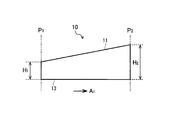
- FIG. 2 is a schematic side view of a press-formed product within a range from a first molding position to a second molding position.
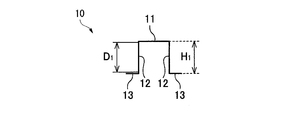
- FIG. 2B is a schematic view of the press-formed product at a first forming position in FIG. 2A, and is a cross-sectional view perpendicular to a first direction.
- FIG. 2B is a schematic view of the press-formed product at a second forming position in FIG. 2A, and is a cross-sectional view perpendicular to a first direction.
- It is a schematic side view showing an example of a press-formed product concerning one embodiment of the present invention.
- FIG. 4 is a schematic side view showing an example of an intermediate product obtained by processing in a first step within a range from a first molding position to a second molding position according to the conventional technique.
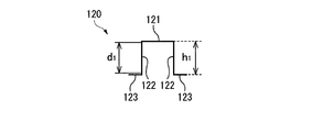
- FIG. 5B is a schematic view of the intermediate product at the first molding position in FIG. 5A, and is a cross-sectional view perpendicular to the first direction.
- FIG. 5B is a schematic view of the intermediate product at the second molding position in FIG. 5A, and is a cross-sectional view perpendicular to the first direction.
- FIG. 6 is a schematic diagram for explaining a method of processing the intermediate product of FIGS. 5A to 5C into a press-formed product.
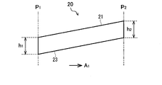
- FIG. 4 is a schematic side view of an intermediate product obtained by processing in the first step and located within a range from a first molding position to a second molding position according to an embodiment of the present invention.
- FIG. 7B is a schematic view of the intermediate product at a first molding position in FIG. 7A, and is a cross-sectional view perpendicular to a first direction.
- FIG. 7B is a schematic view of the intermediate product at the second molding position in FIG. 7A, and is a cross-sectional view perpendicular to the first direction.
- FIG. 8 is a schematic diagram for explaining a method of processing the intermediate product of FIGS. 7A to 7C into a press-formed product. It is a schematic perspective view showing a part of intermediate product concerning one embodiment of the present invention.
- FIG. 3 is a schematic cross-sectional view of the anvil of the second mold at the first molding position.
- FIG. 1 is a schematic perspective view illustrating an example of a press-formed product according to an embodiment of the present invention.
- the numerical range represented by using “to” means a range including numerical values described before and after “to” as a lower limit and an upper limit.
- the term "step” is used not only for an independent step but also for the case where the intended purpose of the step is achieved even if it cannot be clearly distinguished from other steps. included.
- each element of the following embodiments can be combined with each other.
- FIG. 1 is a schematic perspective view showing a press-formed product 10 to be formed according to the present embodiment.
- the press-formed product 10 of the present embodiment is a hat-shaped component having a top plate portion 11, a vertical wall portion 12 connected to the top plate portion 11, and a flange portion 13 connected to the vertical wall portion 12.
- Top plate portion 11, the portion extending in the first direction A 1 (hereinafter, "first extending portion 11a”) and the portion extending in a second direction A 2 is a direction different from the first direction A 1 ( Hereinafter, the “second extending portion 11b”).
- Press-molded product 10 of the present embodiment in a cross section perpendicular to the first direction A 1 of the first extending portion 11a, has a shape in which a pair of vertical wall portions 12 at opposite ends of the top plate portion 11 is provided, in the cross section perpendicular to the second direction a 2 of the second extending portion 11b, while the vertical wall portion 12 only at the ends of the top plate portion 11 is in the provided shape.
- the vertical wall portion 12 extends in a direction perpendicular to the plate surface of the top plate portion 11, but the angle formed by the vertical wall portion 12 and the top plate portion 11 is Not limited to vertical.
- the angle (inner angle) formed between the vertical wall portion 12 and the top plate portion 11 may exceed 90 °, and the vertical wall portion 12 may be inclined with respect to the top plate portion 11. Further, the vertical wall portion 12 may be partially or entirely inclined with respect to the plate surface of the top plate portion 11 over the first direction A 1 , the second direction A 2, and a curved portion 11c described later. Good.
- first direction A 1 and second direction A 2 are defined for convenience of description, and the first direction A 1 shown in FIG. 1 is referred to as a second direction. it may be referred to as a second direction a 2 shown in FIG. 1 to the first direction.
- the first direction A 1 and a second direction A 2 are different directions, when viewed press molded article 10 from a direction perpendicular to the top plate portion 11, the second direction A 2 is a first direction intersects with respect to A 1.
- a center pillar outer For the press-molded product 10, for example, a center pillar outer, a first direction A 1 is the vehicle height direction, the second direction A 2 is vehicle length direction, the end portion and the roof side of the first extending portion 11a sill mounted side The portion between the rail and the second extending portion 11b corresponds to the end on the side sill attachment side.
- one end of the first extension portion 11a is connected to a part of the second extension portion 11b, and the top plate portion 11 is a plane viewed from a direction perpendicular to the plate surface of the top plate portion 11. It is formed in a T shape when viewed.
- the first extension portion 11a and the second extension portion 11b of the top plate portion 11 are smoothly connected so as to be curved in an arc shape, and the side where the curvature is reduced with respect to one arc is defined as the outside of the arc. If the side where the curvature increases is called the inside of the arc, the top plate portion 11 has a shape in which a plate surface exists outside the arc.
- an arcuately curved portion at a location where the first extended portion 11a and the second extended portion 11b are connected is referred to as a "curved portion 11c".
- the vertical wall portion 12 also follows and is connected to the curved portion 11c of the top plate portion 11, and the vertical wall portion 12 connected to the curved portion 11c is curved. Since the flange portion 13 also follows and is connected to the curved vertical wall portion 12, the flange portion 13 is also curved at the curved portion 11c of the top plate portion 11.
- FIG. 2A is curved arbitrary position in the first direction A 1 shown in FIG. 1 (hereinafter, "first molding position P 1") and, than the first molding position P 1 in the first direction A 1
- second molding position P 2 It is a schematic side view of the press-formed product 10 within the range of the position on the part 11c side
- FIG. 2B is a schematic cross-sectional view of the press-formed product 10 at the first molding position P1 in FIG. 2A.
- FIG. 2C is a schematic cross-sectional view of the press-formed product 10 at the second molding position P2 in FIG. 2A. Sectional view here illustrates the cross-section perpendicular to the first direction A 1.
- the press-molded product 10 the product height from the flange portion 13 of the first molding position P 1 is the height of the top plate portion 11 (hereinafter, "first product height is H 1 ”) is the product height from the second forming position P 2 flange portion 13 at a height of up to the top plate portion 11 (hereinafter,” second product height H 2 ") lower than ing.
- first product height H 1
- second product height H 2 second product height
- the vertical wall portion 12 of the first molding position P 1 is a line length of a cross-section perpendicular to the direction A 1 (top plate portion 11 side of the R blind flange
- the length of the straight line between the end of the portion 13 and the stop R) is a vertical length which is a first vertical wall line length D 1 and a line length of a cross section perpendicular to the first direction A 1 at the second molding position P 2 .
- the wall line length (the length of the straight line between the stop at the top plate portion 11 side and the stop at the flange portion 13 side) is referred to as a second vertical wall line length D2.
- R stop in the present embodiment is a boundary between a curved region and a plane region.
- the product height of the press-molded product 10 is continuously increased from the first forming position P 1 toward the second molding position P 2, describes an example in which the product height changes
- the product height of the press-formed product 10 is not limited to an example in which the height is continuously increased. Changing areas of the product height, may be contained in a portion between the first molding position P 1 of the second forming position P 2.
- the product height may be the product height has become continuously lower.
- the period from the first molding position P 1 of the press-molded product 10 to the second forming position P 2 part a product height increases continuously lower becomes part may be mixed.
- the press-molded product 10, the product height may include portions which do not change during the period from the first forming position P 1 to a second forming position P 2.
- FIGS. 3 and 4 are schematic side views for illustrating a modified example of the press-formed product 10.
- the first molding position P 1 over the second forming position P 2 the product height H of the press-molded product 10 is changed stepwise.
- the first molding position P 1 over the second forming position P 2 when viewed from a direction perpendicular to the wall surface of the vertical wall portion 12, the top plate portion 11 and the flange portion 13 is curved
- the product height H is changing continuously.
- a press-formed product 10 as shown in FIGS. 3 and 4 is also included in the present invention.
- the press-formed product according to the present embodiment has a ratio (H max / H min) between the maximum product height H max of the press-formed product 10 and the minimum product height H min of the press-formed product 10 in the first stretched portion 11a. ) Preferably satisfy the following relationship (Equation 1).
- the above expression 1 is satisfied not only in the above-described first extending portion 11a but also in the second extending portion 11b and the curved portion 11c. That is, the ratio (H max) between the maximum product height H max of the press-formed product 10 and the minimum product height H min of the press-formed product 10 from the first stretched portion 11a to the curved portion 11c and the second stretched portion 11b. / H min ) more preferably satisfies the following relationship (Equation 1).
- the maximum product height H max of the press-formed product 10 means a product height at a position where the product height of the press-formed product 10 is highest.
- the minimum product height H min of the press-formed product 10 means a product height at a position where the product height of the press-formed product 10 is the lowest.
- the press-formed product 10 shown in FIGS. 1 and 2 includes a first step of processing a blank into an intermediate product 20 shown in FIGS. 7A to 7C and 9 described later, and the intermediate product 20 shown in FIGS. 1 and 2A. It is manufactured through a second step of processing into a press-formed product 10 shown in FIG. 2C.
- the intermediate product 20 is manufactured by drawing a blank in a first step
- the press-formed product 10 is manufactured by bending the intermediate product 20 in a second step.
- FIGS. 7A to 7C and FIG. I a portion corresponding to the top plate portion 11 of the finished product (press-formed product 10) in the intermediate product 20 shown in FIGS. 7A to 7C and FIG. I do.
- a portion corresponding to the vertical wall portion 12 of the finished product (press-formed product 10) is referred to as an intermediate vertical wall portion 22, and a flange portion 13 of the finished product (press-formed product 10) in the intermediate product 20 is provided.
- the corresponding portion is called an intermediate flange portion 23.
- the vertical wall line length is a line length in a cross section perpendicular to the first direction A 1 (middle top plate portion
- the length of the straight line between the R-stop on the 21 side and the R-stop on the intermediate flange portion 23) is the first intermediate vertical wall line length d 1 , as shown in FIG. 7A and FIG. 7C.
- the intermediate vertical wall portion 22 in the two, between the first vertical wall line length is a line length in a cross section perpendicular to the direction a 1 (R stubbornly intermediate top panel section 21 side and the intermediate flange portion 23 side of the R blind Is the second intermediate vertical wall line length d 2
- the molding height at the first molding position P 1 from the intermediate flange portion 23 to the intermediate top plate portion 21 is the first molding length.
- height h 1 the height from the second forming position P 2 intermediate flange section 23 in to the intermediate top panel section 21 formed The height referred to as the second forming height h 2.
- FIG. 5A is a side view illustrating an example of the intermediate product 120 according to the related art.
- FIG. 5B is a schematic sectional view of the intermediate product 120 at the first molding position P1 in FIG. 5A.
- FIG. 5C is a schematic sectional view of the intermediate product 120 at the second molding position P2 in FIG. 5A. Sectional view here illustrates the cross-section perpendicular to the first direction A 1.
- the angle a middle top plate portion 121 and the intermediate vertical wall portion 122 is It becomes vertical, and like the first forming height h 1 and the second forming height h 2 of the intermediate product 120 is the same, the processing in the first step are being subjected.
- the first forming height h 1 is the first product has become the height H 1 and the same press-formed product 10 is finished as shown in FIG. 2B, the first intermediate vertical wall of the intermediate product 120 line length d 1 is also the same as those vertical wall line length D 1 first of the press-molded product 10 shown in Figure 2B. Therefore, the intermediate product 120 in FIG.
- 5A ⁇ 5C are shaped in a first molding position P 1 has become equivalent to the shape of the press-molded product 10 of the first molding position P 1.
- the intermediate product 120 in FIG. 5A ⁇ 5C are provided second forming height h 2 different from the second product height H 2 of the press-molded product 10 shown in FIG. 2C, similarly, a second also the intermediate vertical wall line length d 2 is different from the second vertical wall line length D 2.
- the second intermediate vertical wall line shown in FIG. the length d 2 it is necessary to process to match the second vertical wall line length D 2 of the press-molded product 10 shown in FIG. 2C. That is, the intermediate flange portion 123 is bent back as shown in FIG. 6 by the processing in the second step, and the flange portion 13 as the press-formed product 10 needs to be newly formed on the plate surface of the intermediate flange portion 123. .
- the cross-sectional shape of the press-formed product 10 after bending and stretching is indicated by a broken line.
- FIG. 7A is a side view showing the intermediate product 20 manufactured by the processing in the first step, according to an embodiment of the present invention.
- FIG. 7B is a schematic sectional view of the intermediate product 20 at the first molding position P1 in FIG. 7A.
- FIG. 7C is a schematic sectional view of the intermediate product 20 at the second molding position P2 in FIG. 7A. Sectional view here illustrates the cross-section perpendicular to the first direction A 1.
- the first forming height h 1 and the second forming height h 2 are the same.
- the cross-sectional shape at the second molding position P2 shown in FIG. 7C is different from the cross-sectional shape of the conventional intermediate product 120 shown in FIG. 5C. More specifically, in the conventional intermediate product 120 shown in FIG. 5C, the angle of the second intermediate top panel section 21 in the molding position P 2 of the intermediate vertical wall portion 22 is perpendicular, the second intermediate Tatekabesen the length d 2 is smaller than the second vertical wall line length D 2 of the press-molded product 10 is finished.
- the second intermediate vertical wall line length d 2 is the same as those vertical wall line length D 2 second of the press-molded product 10.
- Intermediate vertical wall line length d 2 of the intermediate product 20 in the second shown in Fig. 7C is a second identical vertical wall line length D 2 of the press-molded product 10, the second intermediate vertical wall line length d 2 When the second vertical wall line length D 2 may not be necessarily the same. Similarly, the first intermediate vertical wall line length d 1 first vertical wall line length D 1 also may not necessarily identical.
- the ratio (d 1 / D 1 ) of the first intermediate vertical wall line length d 1 to the first vertical wall line length D 1 is 0.80 to 1. 20 should be satisfied. That is, 0.80 ⁇ (d 1 / D 1 ) ⁇ 1.20 is satisfied.
- d 1 / D 1 is less than 0.80, the boundary between the intermediate flange portion 23 and the intermediate vertical wall portion 22 is located at the vertical wall portion 12 of the press-formed product 10 which is a finished product. For this reason, a pattern residue tends to occur on the vertical wall portion 12 of the press-formed product 10.
- d 1 / D 1 It is more preferred lower limit of d 1 / D 1 is 0.90, that is, d 1 / D 1 ⁇ 0.90.
- d 1 / D 1 is 0.90 or more, the remaining pattern of the vertical wall portion 12 of the press-formed product 10 can be more stably suppressed.
- the upper limit of d 1 / D 1 is more preferably 1.10.
- d 1 / D 1 is equal to or less than 1.10, the remaining pattern of the flange portion 13 can be more stably suppressed.
- the ratio (d 2 / D 2 ) of the second intermediate vertical wall line length d 2 to the second vertical wall line length D 2 is 0.80 to 0.80. It suffices to satisfy 1.20. That is, 0.80 ⁇ (d 2 / D 2 ) ⁇ 1.20 is satisfied.
- d 2 / D 2 is less than 0.80, the boundary between the intermediate flange portion 23 and the intermediate vertical wall portion 22 is located on the vertical wall portion 12 of the press-formed product 10 which is a finished product. For this reason, a pattern residue tends to occur on the vertical wall portion 12 of the press-formed product 10.
- d 2 / D 2 ⁇ 0.90 that is, the lower limit of d 2 / D 2 is 0.90.
- d 2 / D 2 ⁇ 1.10 that is, the upper limit of d 2 / D 2 is 1.10.
- the ratio (h 2 / h 1 ) between the second forming height h 2 and the first forming height h 1 of the intermediate product 20 is 0.80 to 1 .20, that is, 0.80 ⁇ (h 2 / h 1 ) ⁇ 1.20.
- h 2 / h 1 is less than 0.80, when bending the intermediate product 20 in the second step, distortion occurs between the first forming position P 1 and the second forming position P 2 , The top plate 11 is partially stressed. For this reason, wrinkles are easily generated in the top plate portion 11 of the press-formed product 10.
- the lower limit of h 2 / h 1 0.90 i.e. more preferably h 2 / h 1 ⁇ 0.90
- h 2 / h 1 Is more preferably 1.10, that is, h 2 / h 1 ⁇ 1.10.
- the intermediate product 20 that satisfies the above conditions is processed so that the press-formed product 10 is formed in the second process.
- the generation of wrinkles and remaining patterns can be prevented. For this reason, the appearance quality of the press-formed product 10 can be improved.
- the material of the blank is not particularly limited, but, for example, a steel plate is used.
- wrinkles of the top plate portion 11 and remaining patterns of the vertical wall portion 12 can be suppressed even for a high-tensile material having high molding difficulty. Therefore, when a steel plate having a tensile strength of 590 MPa or more is used as the blank material, the effect of improving the appearance quality is more remarkably exhibited.
- the angle formed by the intermediate top plate portion 21 and the intermediate vertical wall portion 22 at the time of processing in the first step of the present embodiment is determined by the vertical wall line length and the product height of the press-formed product 10 and the top plate portion 11. It is appropriately set according to the angle between the vertical wall portion 12 and the like.
- any of the position P n, the position of the intermediate product 20 between the first molding position P 1 and the second molding position P 2 of the present embodiment in the press molded article 10 shown in FIGS. 2A ⁇ 2C the intermediate vertical wall line length d n is the second intermediate vertical wall line length d 2 following an intermediate product 20 in the second molding position P 2.
- an arbitrary position P n, in the second and the molding position P 2, the width of the intermediate top panel section 21 (line length of the intermediate top panel section 21 in the first cross-section perpendicular to the direction A 1) is identical If it is, the angle between the intermediate top panel section 21 and the intermediate vertical wall portion 22 at an arbitrary position P n (an interior angle) of the intermediate top panel section 21 and the intermediate vertical wall portion in a second molding position P 2 22 (inner angle).
- FIG. 9 is a schematic perspective view showing a part of the intermediate product 20 according to the present embodiment.
- Perspective view of FIG. 9, not the entire intermediate product 20, shows a part of the intermediate product 20 in the range of, as shown in FIG. 7A, the first molding position P 1 to a second forming position P 2 is there.
- the first intermediate vertical wall line length d 1 is a first vertical wall line length D 1 is the same
- the second intermediate vertical wall line length d 2 and the second vertical wall line length D 2 are the same has been described an example in which the first forming height h 1 and the second forming height h 2 performs the processing in the first step to be the same.
- the present invention is not limited to this embodiment.
- the manufacturing equipment 30 for the press-formed product 10 includes a first mold 40 for processing the blank 60 into the intermediate product 20 and a second mold 40 for processing the intermediate product 20 into the press-formed product 10. And a mold 50.
- the first die 40 is a drawing die configured to perform drawing
- the second die 50 is a bending die configured to perform bending. It is a mold.
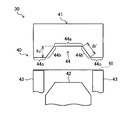
- FIG. 10 is a schematic cross-sectional view of the first mold 40 in a second molding position P 2 of the present embodiment.
- the first die 40 of the present embodiment surrounds the periphery of the punch 42 and the processing die 41 for drawing, which is disposed as an upper die, the punch 42 facing the processing die 41 which is disposed as a lower die.
- Blank holder 43 arranged as described above.
- the processing die 41 has a concave portion 44 that meshes with the top of the punch 42.
- the concave portion 44 has a surface 44a having the same shape as the shape of the intermediate top plate portion 21 and a surface 44b having the same shape as the shape of the intermediate vertical wall portion 22 connected to the surface.
- a surface 44c connected to the surface 44b is formed in a portion of the processing die 41 facing the blank holder 43. Since these surfaces 44a to 44c are formed on the processing die 41, when the first mold 40 is closed, the intermediate top plate portion 21, the intermediate vertical wall portion 22, and the intermediate flange portion of the intermediate product 20 are formed. The molding of the part 23 is performed. That is, the surfaces 44a to 44c of the processing die 41 correspond to a portion for forming the intermediate top plate portion 21, a portion for forming the intermediate vertical wall portion 22, and a portion for forming the intermediate flange portion 23, respectively.
- the portion of the first mold 40 where the intermediate top plate portion 21 is formed is the intermediate top plate forming portion 44a
- the portion where the intermediate vertical wall portion 22 is formed is the intermediate vertical wall forming portion 44b
- a portion where the intermediate flange portion 23 is formed is referred to as an intermediate flange forming portion 44c.
- the processing die 41 and the blank holder 43 are lowered or the punch is pressed while the blank 60 is held by the processing die 41 and the blank holder 43.
- the blank 60 is pushed into the concave portion 44 of the processing die 41 as shown in FIG. 11.
- the blank 60 is processed into a shape following the shape of the concave portion 44 of the processing die 41, and the intermediate product 20 is manufactured.
- Figure 12 is a schematic sectional view showing a working die 41 of the first die 40 in the first molding position P 1 of the present embodiment.
- the first intermediate vertical wall molded portion 44b in the molding position P 1 the vertical wall line is the line length in the cross section perpendicular to the first direction A 1
- the length (the length of the straight line between the R stop on the intermediate top plate forming portion 44a side and the R stop on the intermediate flange forming portion 44c) is the first intermediate vertical wall line length d 1 ′
- blind R of the first vertical wall line length is a line length in a cross section perpendicular to the direction a 1 (blind intermediate top plate forming portion 44a side R and the intermediate flange-forming portion 44c side straight length) the second intermediate vertical wall line length d 2 '
- molded height is the height from the first intermediate flange forming portion 44c at the molding position P 1 to the intermediate top
- the first intermediate vertical wall line length d 1 , the first molding height h 1 , the second intermediate vertical wall line length d 2 , and the second intermediate vertical wall length d 1 of the intermediate product 20 obtained by processing with the first mold 40.
- forming height h 2 of the first intermediate vertical wall line length d 1 of the first die 40 ', the first forming height h 1', the second intermediate vertical wall line length d 2 ', and Each of them is equal to the second molding height h 2 ′.
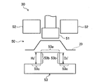
- FIG. 13 is a schematic sectional view of a second mold 50 in the second molding position P 2 of the present embodiment.
- the second mold 50 of the present embodiment includes a pad 51 arranged as an upper mold, a processing die 52 arranged to surround the periphery of the pad 51 for bending, and an anvil 53 arranged as a lower mold. It has.
- the anvil 53 has a surface 53a having the same shape as the top plate portion 11 of the press-formed product 10, a surface 53b having the same shape as the shape of the vertical wall portion 12 of the press-formed product 10 connected to the surface 53a, and a surface 53b having the same shape.
- the surfaces 53a to 53c of the anvil 53 correspond to a portion for forming the top plate portion 11, a portion for forming the vertical wall portion 12, and a portion for forming the flange portion 13, respectively.
- the portion of the second mold 50 where the top plate portion 11 is formed is the top plate forming portion 53a
- the portion where the vertical wall portion 12 is formed is the vertical wall forming portion 53b
- the flange portion 13 is The part to be formed is referred to as a flange forming part 53c.
- the intermediate top plate portion 21 is positioned between the top plate forming portion 53a of the anvil 53 and the pad 51.
- the processing die 52 is lowered as shown in FIG. Thereby, the intermediate product 20 is processed into a shape following the top plate forming portion 53a, the vertical wall forming portion 53b, and the flange forming portion 53c of the anvil 53, and the press-formed product 10 is manufactured.
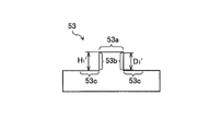
- Figure 15 is a schematic diagram showing a second anvil 53 of the die 50 in the first molding position P 1 of the present embodiment.
- the second die 50 the first vertical wall molded portion 53b in the molding position P 1 of the first cross-section perpendicular to the direction A 1
- the first vertical wall line length D 1 ′ and the second vertical wall line length (the length of the straight line between the R-stop on the top plate forming portion 53 a side and the R-stop on the flange forming portion 53 c), which is the line length, are used.
- the first vertical wall line length is a line length in a cross section perpendicular to the direction a 1 (R stoppage of the top mold portion 53a side of the flange forming portion 53c side blind vertical wall line length D 2 of the length of the straight line) a second between '
- the product height is the height from the flange forming portion 53c to the top plate forming portion 53a in the first molding position P 1 first product height H 1 '
- the product height H 2 is determined by the first vertical wall line length D 1 ′ of the second mold 50, the first product height H 1 ′, the second vertical wall line length D 2 ′, and the second vertical wall line length D 2 ′. It is equal to the product height H 2 ′.
- an intermediate product 20 of the present embodiment the first intermediate vertical wall line length d 1 of the first vertical wall line length D 1 ratio, length d 2 and a second second intermediate vertical wall line the ratio of the vertical wall line length D 2, and the second forming height h 2 first ratio forming height h 1 of, in which each satisfy 0.80 to 1.20.
- the ratio of the first intermediate vertical wall line length d 1 ′ to the first vertical wall line length D 1 ′, the second intermediate vertical wall line length d 1 The ratio of 2 ′ to the second vertical wall line length D 2 ′ and the ratio of the second forming height h 2 ′ to the first forming height h 1 ′ satisfy the same conditions as the intermediate product 20.
- the occurrence of wrinkles and remaining patterns in the press-formed product 10 can be suppressed.
- the first mold 40 and the second mold 50 have the first intermediate vertical wall line length d 1 ′ and the first vertical wall line length. It is configured such that the ratio of D 1 ′ (d 1 ′ / D 1 ′) is 0.80 to 1.20. That is, 0.80 ⁇ (d 1 ′ / D 1 ′) ⁇ 1.20 is satisfied.
- d 1 ′ / D 1 ′ is less than 0.80, the pattern remains easily formed on the vertical wall portion 12 of the press-formed product 10.
- d 1 ′ / D 1 ′ is more than 1.20, pattern residue is likely to be generated on the flange portion 13 of the press-formed product 10.
- the lower limit of d 1 ′ / D 1 ′ is more preferably 0.90.
- the upper limit of d 1 ′ / D 1 ′ is more preferably 1.10.
- the first mold 40 and the second mold 50 use the second intermediate vertical wall line length d 2 ′ and the second vertical wall line length.
- the ratio of D 2 ′ (d 2 ′ / D 2 ′) is configured to be 0.80 to 1.20. That is, 0.80 ⁇ (d 2 ′ / D 2 ′) ⁇ 1.20 is satisfied.
- d 2 ′ / D 2 ′ is less than 0.80, a pattern residue is likely to be generated on the vertical wall portion 12 of the press-formed product 10.
- d 2 ′ / D 2 ′ is more than 1.20, pattern residue is likely to occur on the flange portion 13 of the press-formed product 10.
- the lower limit of d 2 ′ / D 2 ′ is more preferably 0.90.
- the upper limit of d 2 ′ / D 2 ′ is more preferably 1.10.
- the first mold 40 has a ratio (h 2 ′ / h 2 ′) between the second molding height h 2 ′ and the first molding height h 1 ′.
- h 1 ′) is set to be 0.80 to 1.20. That is, 0.80 ⁇ (h 2 ′ / h 1 ′) ⁇ 1.20 is satisfied.
- h 2 ′ / h 1 ′ is less than 0.80, wrinkles are likely to be generated on the top plate 11 of the press-formed product 10.
- h 2 ′ / h 1 ′ exceeds 1.20, wrinkles are likely to occur on the top plate 11 of the press-formed product 10.
- the lower limit of h 2 ′ / h 1 ′ is more preferably 0.90.
- the upper limit of h 2 ′ / h 1 ′ is more preferably 1.10.
- the press-formed product 10 may have a left-right asymmetric shape.
- the vertical wall line length of the pair of vertical wall portions 12 in a cross section perpendicular to the first direction A 1 as described above may be different, with one vertical wall portion 12 and the top plate portion 11
- the angle formed and the angle formed by the other vertical wall portion 12 and the top plate portion 11 may be different from each other. Even in this case, if each of the vertical wall portions 12 satisfies the above-described ratio between the intermediate vertical wall line length and the vertical wall line length, the appearance quality of the press-formed product 10 can be improved.
- the method of forming the press-formed product 10 in the first stretched portion 11a has been described.
- the press-formed product having a shape in which the product height changes toward the curved portion 11c also in the second stretched portion 11b. If it is 10, the same molding method can be applied.
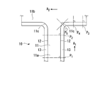
- FIG. 16 is a schematic plan view of the press-formed product 10 viewed from a direction perpendicular to the plate surface of the top plate portion.
- a first molding position P 1 and the second molding position P 2 is positioned in the first extending portion 11a.
- FIG. 16 is a schematic plan view of the press-formed product 10 viewed from a direction perpendicular to the plate surface of the top plate portion.
- a first molding position P 1 and the second molding position P 2 is positioned in the first extending portion 11a.
- FIG. 16 is a schematic plan view of the press-formed product 10 viewed from a direction perpendicular to the plate surface of the top plate portion.
- a first molding position P 1 and the second molding position P 2 is positioned in the first extending portion 11a.
- the intermediate vertical wall line length d 4 and the fourth vertical wall line length D 4 are such that d 3 / D 3 is 0.80 to 1.20, d 4 / D 4 is 0.80 to 1.20, and h 4 / H 3 may satisfy the relationship of 0.80 to 1.20.
- the fifth forming height h 5 of the fifth intermediate Tatekabesen the vertical wall line length D 5 of length d 5 and the fifth, second forming height h 2 may be replaced each second in the intermediate vertical wall line length d 2 and a second vertical wall line length D 2 .
- the fifth forming height h 5 of the intermediate vertical wall line length d 5 and the fifth vertical wall line length D 5 of the fifth, fourth forming height h 4, a fourth intermediate vertical wall line length d 4 and the fourth vertical wall line length D 4 may be used.
- the shape of the press-formed product 10 is not limited to the shape described in the above embodiment.
- the press-formed product 10 may have, for example, an L-shaped shape in which one end of a first extension 11a and one end of a second extension 11b are connected via a curved portion 11c.
- the press-formed product 10 further includes a third extending portion (not shown) which is a portion extending in a third direction (not shown) such as a Y-shape, for example, and one end of the first extending portion 11a, One end of the second extended portion 11b and one end of the third extended portion may be connected to each other via the curved portion 11c.
- the press-formed product 10 is, for example, an automobile part including at least one of a T-shape, an L-shape, and a Y-shape in plan view.
- the press-formed product is, for example, a center pillar outer, a front pillar lower or a side panel outer.
- the first direction described above may be replaced with a third direction, and in this third direction as well, the press-formed product 10 in which the third extending portion changes in product height toward the curved portion 11c. Then, in the third direction, the same molding positions as the above-described first molding position P 1 to fourth molding position P 4 are set, and the method of manufacturing a press-molded product according to the above embodiment is set. Can be applied.
- FIG. 17 is a schematic perspective view showing another example of the press-formed product 10 according to the embodiment.
- Press-molded product 10 in FIG. 17, the overall configuration is similar to the press-molded product 10 shown in FIG. 1, the first product height at the first molding position P 1 H 1 and second molding position the difference between the second product height H 2 at P 2 is smaller than the example of FIG.
- the drawing is performed in the first step, but the processing method in the first step is not limited to the drawing.
- the ratio (d 1 / D 1 ) of the first intermediate vertical wall line length d 1 to the first vertical wall line length D 1 satisfies 0.80 to 1.20
- 2, the ratio (d 2 / D 2 ) of the intermediate vertical wall line length d 2 to the second vertical wall line length D 2 satisfies 0.80 to 1.20
- the second molding height h 2 and the first Any processing method may be used as long as an intermediate product 20 that satisfies the ratio (h 2 / h 1 ) of the molding height h 1 (h 2 / h 1 ) of 0.80 to 1.20 is obtained.
- the processing method in the second step is not limited to bending.
- the first die 40 is a drawing die configured to perform drawing, but the first die 40 is a drawing die. Not limited.
- the first mold 40 has a ratio (d 1 ′ / D 1 ′) of the first intermediate vertical wall line length d 1 ′ to the first vertical wall line length D 1 ′ of 0.80 to 1.20.
- the ratio (d 2 ′ / D 2 ′) of the second intermediate vertical wall line length d 2 to the second vertical wall line length D 2 satisfies 0.80 to 1.20, and the second forming height It suffices if the ratio (h 2 ′ / h 1 ′) between h 2 ′ and the first molding height h 1 ′ satisfies 0.80 to 1.20.
- the second mold 50 is not limited to a bending mold configured to perform a bending process.
- a molding simulation (software used: J-STAMP) of a press-formed product having a shape as shown in FIG. 1 was performed to evaluate the appearance of the press-formed product.
- the forming simulation was performed as a first step to obtain an intermediate product and a press-formed product (the first product height was 80 mm and the second product height was 96 mm) satisfying the conditions shown in Table 1 below.
- the processing and the bending as the second step were set as manufacturing conditions.
- the blank is a steel plate having a tensile strength of 980 MPa.
- the appearance quality is evaluated by observing the top plate, vertical wall, and flange of the press-formed product of the analysis model with shading display, and determining the occurrence of wrinkles and remaining patterns by sensory evaluation. I was
- the present invention can be used for manufacturing press-formed products of automobiles.
Landscapes
- Engineering & Computer Science (AREA)
- Mechanical Engineering (AREA)
- Shaping Metal By Deep-Drawing, Or The Like (AREA)
- Bending Of Plates, Rods, And Pipes (AREA)
Abstract
本発明では、天板部(11)と、縦壁部(12)と、フランジ部(13)とを有し、第1の成形位置P1から第2の成形位置P2にかけてフランジ部(13)から天板部(11)までの高さが第1の製品高さH1から第2の製品高さH2まで変化するプレス成形品(10)であって、第1の工程において、ブランクを加工することで、第1の中間縦壁線長d1/第1の縦壁線長D1:0.80~1.20、第2の中間縦壁線長d2/第2の縦壁線長D2:0.80~1.20、第2の成形高さh2/第1の成形高さh1:0.80~1.20、を満たす中間製品を製造し、第2の工程において、中間製品を加工することでプレス成形品(10)を製造するプレス成形品の製造方法を提供する。
Description
本発明は、プレス成形品の製造方法および製造設備に関する。
本願は、2018年6月29日に、日本に出願された特願2018-124149号に基づき優先権を主張し、その内容をここに援用する。
本願は、2018年6月29日に、日本に出願された特願2018-124149号に基づき優先権を主張し、その内容をここに援用する。
自動車車体には衝突性能を担保することが求められ、衝突性能の向上を目的とした車体構造の改良が推進されている。これに伴い、自動車車体を構成する部品の形状も複雑化しており、部品の成形難度も高くなってきている。特に、近年は衝突性能の向上と軽量化を両立させるため、素材としてハイテン材(High Tensile Strength Steel Material)が使用されることも多くなり、部材の成形難度が高くなっている。一方で、そのような成形難度の高い部材を製造するための成形技術の改良も進んでいる。特許文献1には湾曲部を有するL字状やT字状等の部品のプレス成形方法が開示されている。特許文献2には、湾曲部を有するL形製品のプレス成形方法が開示されている。
プレス成形で得られるL字状やT字状等の部品は、天板部と、縦壁部と、フランジ部とを有している。例えばセンターピラーアウターのようなプレス成形品は、サイドシルの取付側の端部に近づくほど、フランジ部から天板部までの製品高さが徐々に変化する部品である。このような部品は成形難度が高く、天板部のシワや、縦壁部の模様残り(繰り返しの曲げ加工の際に残る曲げ点の跡)が発生しやすい部品であるが、シワや模様残りが多く発生すると、外観品質が低下することになる。このため、外観品質のさらなる向上のためには、シワや模様残りの発生を安定的に抑える必要がある。
本発明は、上記事情に鑑みてなされたものであり、プレス成形品の外観品質を向上させることを目的とする。
(1)本発明の一態様に係るプレス成形品の製造方法は、第1の方向と第2の方向に延び、かつ第1の方向に延びる部分と第2の方向に延びる部分とが湾曲部を介して繋がる天板部と、天板部に繋がる縦壁部と、縦壁部に繋がるフランジ部とを有し、第1の方向における任意の位置を第1の成形位置、第1の成形位置よりも湾曲部側の位置を第2の成形位置と称したとすると、第1の成形位置から第2の成形位置にかけて、フランジ部から天板部までの高さが第1の製品高さH1から第2の製品高さH2まで変化する、プレス成形品の製造方法であって、中間製品における天板部に相当する部分を中間天板部、中間製品における縦壁部に相当する部分を中間縦壁部、中間製品におけるフランジ部に相当する部分を中間フランジ部と称し、第1の成形位置における中間縦壁部の、第1の方向に垂直な断面の線長を第1の中間縦壁線長d1、第2の成形位置における中間縦壁部の、第1の方向に垂直な断面の線長を第2の中間縦壁線長d2、第1の成形位置における中間フランジ部から中間天板部までの高さを第1の成形高さh1、第2の成形位置における中間フランジ部から中間天板部までの高さを第2の成形高さh2、第1の成形位置における縦壁部の、第1の方向に垂直な断面の線長を第1の縦壁線長D1、第2の成形位置における縦壁部の、第1の方向に垂直な断面の線長を第2の縦壁線長D2と称したとすると、ブランクを加工することで、第1の中間縦壁線長d1/第1の縦壁線長D1:0.80~1.20、第2の中間縦壁線長d2/第2の縦壁線長D2:0.80~1.20、第2の成形高さh2/第1の成形高さh1:0.80~1.20、を満たす中間製品を製造する第1の工程と、中間製品を加工することでプレス成形品を製造する第2の工程と、を有することを特徴とする。
(2)上記(1)に記載のプレス成形品の製造方法において、ブランクは、引張強度が590MPa以上の鋼板であってもよい。
(2)上記(1)に記載のプレス成形品の製造方法において、ブランクは、引張強度が590MPa以上の鋼板であってもよい。
(3)本発明の他の態様に係るプレス成形品の製造設備は、天板部と、天板部に繋がる縦壁部と、縦壁部に繋がるフランジ部とを有するプレス成形品の製造設備であって、ブランクから中間製品への成形を行う第1の金型と、中間製品からプレス成形品への成形を行う第2の金型と、を備え、第2の金型は、第1の方向と第2の方向に延び、かつ第1の方向に延びる部分と第2の方向に延びる部分とが湾曲部を介して繋がる、天板部の成形を行う部分である天板成形部と、縦壁部の成形を行う部分である縦壁成形部と、フランジ部の成形を行う部分であるフランジ成形部と、を有し、第1の方向における任意の位置を第1の成形位置、第1の成形位置よりも湾曲部側の位置を第2の成形位置と称したとすると、第1の成形位置から第2の成形位置にかけて、フランジ成形部から天板成形部までの高さが第1の製品高さH1’から第2の製品高さH2’まで変化し、中間製品における天板部に相当する部分を中間天板部、中間製品における縦壁部に相当する部分を中間縦壁部、中間製品におけるフランジ部に相当する部分を中間フランジ部と称したとすると、第1の金型は、中間天板部の成形を行う部分である中間天板成形部と、中間縦壁部の成形を行う部分である中間縦壁成形部と、中間フランジ部の成形を行う部分である中間フランジ成形部と、を有し、第1の成形位置における中間縦壁成形部の、第1の方向に垂直な断面の線長を第1の中間縦壁線長d1’、第2の成形位置における中間縦壁成形部の、第1の方向に垂直な断面の線長を第2の中間縦壁線長d2’、第1の成形位置における中間フランジ成形部から中間天板成形部までの高さを第1の成形高さh1’、第2の成形位置における中間フランジ成形部から中間天板成形部までの高さを第2の成形高さh2’、第1の成形位置における縦壁成形部の、第1の方向に垂直な断面の線長を第1の縦壁線長D1’、第2の成形位置における縦壁成形部の、第1の方向に垂直な断面の線長を第2の縦壁線長D2’と称したとすると、第1の金型及び第2の金型は、第1の中間縦壁線長d1’/第1の縦壁線長D1’:0.80~1.20、第2の中間縦壁線長d2’/第2の縦壁線長D2’:0.80~1.20、第2の成形高さh2’/第1の成形高さh1’:0.80~1.20、を満たすように構成されていることを特徴とする。
なお、本発明における“第1の成形位置から第2の成形位置にかけて製品高さが変化する”とは、第1の成形位置から第2の成形位置にかけて全体として製品高さが変化していることを意味し、製品高さが必ずしも連続的に変化していなくてもよい。すなわち、第1の成形位置から第2の成形位置までの間に、製品高さが変わらない部分があったとしても、第1の成形位置と第2の成形位置とで製品高さが異なるプレス成形品は、本発明において成形対象となるプレス成形品である。
本発明によれば、プレス成形品の外観品質を向上させることができる。
以下、本発明の一実施形態について、図面を参照しながら説明する。なお、本明細書および図面において、実質的に同一の機能構成を有する要素においては、同一の符号を付することにより重複説明を省略する。
なお、本明細書中において、「~」を用いて表される数値範囲は、「~」の前後に記載される数値を下限値および上限値として含む範囲を意味する。本明細書中において、「工程」との用語は、独立した工程だけではなく、他の工程と明確に区別できない場合であってもその工程の所期の目的が達成されれば、本用語に含まれる。また、以下の実施形態の各要素は、それぞれの組み合わせが可能であることは自明である。
<プレス成形品>
図1は、本実施形態の成形対象となるプレス成形品10を示す概略的な斜視図である。本実施形態のプレス成形品10は、天板部11と、天板部11に繋がる縦壁部12と、縦壁部12に繋がるフランジ部13とを有するハット形状の部品である。天板部11は、第1の方向A1に延びる部分(以下、“第1延伸部11a”)と、第1の方向A1とは異なる方向である第2の方向A2に延びる部分(以下、“第2延伸部11b”)とを有している。本実施形態のプレス成形品10は、第1延伸部11aにおける第1の方向A1に垂直な断面において、天板部11の両端に一対の縦壁部12が設けられた形状を有し、第2延伸部11bにおける第2の方向A2に垂直な断面においては、天板部11の一方の端部にのみ縦壁部12が設けられた形状となっている。
図1は、本実施形態の成形対象となるプレス成形品10を示す概略的な斜視図である。本実施形態のプレス成形品10は、天板部11と、天板部11に繋がる縦壁部12と、縦壁部12に繋がるフランジ部13とを有するハット形状の部品である。天板部11は、第1の方向A1に延びる部分(以下、“第1延伸部11a”)と、第1の方向A1とは異なる方向である第2の方向A2に延びる部分(以下、“第2延伸部11b”)とを有している。本実施形態のプレス成形品10は、第1延伸部11aにおける第1の方向A1に垂直な断面において、天板部11の両端に一対の縦壁部12が設けられた形状を有し、第2延伸部11bにおける第2の方向A2に垂直な断面においては、天板部11の一方の端部にのみ縦壁部12が設けられた形状となっている。
なお、本実施形態のプレス成形品10においては、縦壁部12が天板部11の板面に対して垂直な方向に延びているが、縦壁部12と天板部11が成す角度は垂直に限られない。縦壁部12と天板部11が成す角度(内角)は90°を超えていてもよく、縦壁部12は天板部11に対して傾斜していてもよい。また、縦壁部12は天板部11の板面に対して、第1の方向A1、第2の方向A2および後述する湾曲部11cにわたり、部分的又は全体的に傾斜していてもよい。
また、“第1の方向A1”および“第2の方向A2”の呼称については説明の便宜上、定めたものであり、図1に示す第1の方向A1を第2の方向と称し、図1に示す第2の方向A2を第1の方向と称してもよい。なお、第1の方向A1と第2の方向A2は異なる方向であり、天板部11に垂直な方向からプレス成形品10を見た場合、第2の方向A2は第1の方向A1に対し交差する。プレス成形品10が、例えばセンターピラーアウターの場合、第1の方向A1が車高方向、第2の方向A2が車長方向、第1延伸部11aがサイドシル取付側の端部とルーフサイドレールとの間の部分、第2延伸部11bがサイドシル取付側の端部に相当する。
図1に示すように、第1延伸部11aの一端は第2延伸部11bの途中の部分に繋がっており、天板部11は、天板部11の板面に垂直な方向から見た平面視において、T字状に形成されている。天板部11の第1延伸部11aと第2延伸部11bとの間は、弧状に湾曲するように滑らかに繋がれており、1つの弧に対して曲率が小さくなる側を弧の外側と称し、曲率が大きくなる側を弧の内側と称したとすると、天板部11は、弧の外側に板面が存在する形状となっている。本明細書においては、そのような第1延伸部11aと第2延伸部11bとが繋がれている箇所にある、弧状に湾曲している部分を“湾曲部11c”と称す。縦壁部12は、天板部11の湾曲部11cにも追従して繋がっており、湾曲部11cに繋がる箇所の縦壁部12は湾曲している。また、フランジ部13も湾曲した縦壁部12に追従して繋がっているため、天板部11の湾曲部11cにおいてはフランジ部13も湾曲している。
図2Aは、図1に示す第1の方向A1における任意の位置(以下、“第1の成形位置P1”)と、第1の方向A1において第1の成形位置P1よりも湾曲部11c側の位置(以下、“第2の成形位置P2”)との範囲内にあるプレス成形品10の概略的な側面図である。図2Bに、図2Aの第1の成形位置P1におけるプレス成形品10の概略的な断面図を示す。また、図2Cに、図2Aの第2の成形位置P2におけるプレス成形品10の概略的な断面図を示す。ここでいう断面図は、第1の方向A1に垂直な断面を示す図である。
図2A~図2Cに示すように、プレス成形品10は、第1の成形位置P1におけるフランジ部13から天板部11までの高さである製品高さ(以下、“第1の製品高さH1”)が、第2の成形位置P2におけるフランジ部13から天板部11までの高さである製品高さ(以下、“第2の製品高さH2”)よりも低くなっている。換言すると、本実施形態のプレス成形品10においては、第1の成形位置P1から第2の成形位置P2にかけて、製品高さが第1の製品高さH1から第2の製品高さH2まで高くなっている。
本明細書においては、第1の成形位置P1における縦壁部12の、第1の方向A1に垂直な断面の線長である縦壁線長(天板部11側のR止まりとフランジ部13側のR止まりとの間の直線の長さ)を第1の縦壁線長D1、第2の成形位置P2における第1の方向A1に垂直な断面の線長である縦壁線長(天板部11側のR止まりとフランジ部13側のR止まりとの間の直線の長さ)を第2の縦壁線長D2と称す。図2Bに示す例における第1の縦壁線長D1は第1の製品高さH1と等しい長さであるが、第1の縦壁線長D1は第1の製品高さH1よりも長くてもよい。同様に、第2の縦壁線長D2も第2の製品高さH2より長くてもよい。なお本実施形態における「R止まり」とは、湾曲した領域と平面領域との境界とする。
なお、本実施形態では、プレス成形品10の製品高さが第1の成形位置P1から第2の成形位置P2にかけて連続的に高くなることで、製品高さが変化する例について説明しているが、プレス成形品10の製品高さは、連続的に高くなる例に限られない。製品高さの変化する領域は、第1の成形位置P1から第2の成形位置P2の間に一部分でも含まれていればよい。例えば、プレス成形品10の第1の成形位置P1から第2の成形位置P2にかけて、製品高さが連続的に低くなっていてもよい。あるいは、プレス成形品10の第1の成形位置P1から第2の成形位置P2にかけて、製品高さが連続的に低くなる部分と高くなる部分が混在していてもよい。また、プレス成形品10は、第1の成形位置P1から第2の成形位置P2までの間に製品高さが変化しない部分が含まれていてもよい。
図3および図4は、プレス成形品10の変形例を例示するための概略的な側面図である。図3の例では、第1の成形位置P1から第2の成形位置P2にかけて、プレス成形品10の製品高さHが段階的に変化している。図4は、第1の成形位置P1から第2の成形位置P2にかけて、縦壁部12の壁面に垂直な方向から見た場合に、天板部11およびフランジ部13が湾曲しているプレス成形品10の例である。図4に示す例では第1の成形位置P1から第2の成形位置P2にかけて、製品高さHが連続的に変化している。図3および図4に示すようなプレス成形品10も本発明に含まれる。
なお、上記断面は、第1の成形位置P1又は第2の成形位置P2における、天板部11の板面に垂直な方向から見た場合の、天板部11と縦壁部12とがなす稜線(稜線が曲線の場合には、成形位置における法線)に垂直な断面である。
(最大の製品高さHmaxと最小の製品高さHmin)
本実施形態に係るプレス成形品は、第1延伸部11aにおけるプレス成形品10の最大の製品高さHmaxとプレス成形品10の最小の製品高さHminとの比(Hmax/Hmin)が、下記の(式1)の関係を満たすことが好ましい。
本実施形態に係るプレス成形品は、第1延伸部11aにおけるプレス成形品10の最大の製品高さHmaxとプレス成形品10の最小の製品高さHminとの比(Hmax/Hmin)が、下記の(式1)の関係を満たすことが好ましい。
(Hmax/Hmin)>1.20 式1
また、上記の式1は、上述した第1延伸部11aのみならず、第2延伸部11bおよび湾曲部11cにおいても満たされることが、より好ましい。すなわち、第1延伸部11aから湾曲部11cおよび第2延伸部11bにかけて、プレス成形品10の最大の製品高さHmaxとプレス成形品10の最小の製品高さHminとの比(Hmax/Hmin)が、下記の(式1)の関係を満たすことがより好ましい。
(Hmax/Hmin)>1.20 式1
プレス成形品10の最大の製品高さHmaxとは、プレス成形品10の製品高さが最も高くなる位置における製品高さを意味する。また、プレス成形品10の最小の製品高さHminとは、プレス成形品10の製品高さが最も低くなる位置における製品高さを意味する。
<プレス成形品の製造方法>
図1および図2に示すプレス成形品10は、ブランクを、後述する図7A~図7Cおよび図9に示す中間製品20に加工する第1の工程と、当該中間製品20を図1および図2A~図2Cに示すプレス成形品10に加工する第2の工程を経て製造される。本実施形態の製造方法では、第1の工程においてブランクの絞り加工により中間製品20を製造し、第2の工程において中間製品20の曲げ加工によりプレス成形品10を製造する。
図1および図2に示すプレス成形品10は、ブランクを、後述する図7A~図7Cおよび図9に示す中間製品20に加工する第1の工程と、当該中間製品20を図1および図2A~図2Cに示すプレス成形品10に加工する第2の工程を経て製造される。本実施形態の製造方法では、第1の工程においてブランクの絞り加工により中間製品20を製造し、第2の工程において中間製品20の曲げ加工によりプレス成形品10を製造する。
なお、本明細書においては、後述する図7A~図7C、および図9に示す中間製品20における、完成品(プレス成形品10)の天板部11に相当する部分を中間天板部21とする。同様に中間製品20における、完成品(プレス成形品10)の縦壁部12に相当する部分を中間縦壁部22とし、中間製品20における、完成品(プレス成形品10)のフランジ部13に相当する部分を中間フランジ部23と称す。また、図7Aおよび図7Bに示すように第1の成形位置P1における中間縦壁部22の、第1の方向A1に垂直な断面における線長である縦壁線長(中間天板部21側のR止まりと中間フランジ部23側のR止まりとの間の直線の長さ)を第1の中間縦壁線長d1、図7Aおよび図7Cに示すように第2の成形位置P2における中間縦壁部22の、第1の方向A1に垂直な断面における線長である縦壁線長(中間天板部21側のR止まりと中間フランジ部23側のR止まりとの間の直線の長さ)を第2の中間縦壁線長d2、第1の成形位置P1における中間フランジ部23から中間天板部21までの高さである成形高さを第1の成形高さh1、第2の成形位置P2における中間フランジ部23から中間天板部21までの高さである成形高さを第2の成形高さh2と称す。
ここで、本実施形態の製造方法を説明する前に、説明の便宜上、従来技術について説明する。図5Aは、従来技術に係る中間製品120の一例を示す側面図である。図5Bは、図5Aの第1の成形位置P1における中間製品120の概略的な断面図である。図5Cは、図5Aの第2の成形位置P2における中間製品120の概略的な断面図である。ここでいう断面図は、第1の方向A1に垂直な断面を示す図である。
図5A~図5Cに示す例では、中間製品120の第1の成形位置P1から第2の成形位置P2までの範囲において、中間天板部121と中間縦壁部122とがなす角が垂直となり、かつ中間製品120の第1の成形高さh1と第2の成形高さh2が同一となるように、第1の工程における加工が施されている。また、第1の成形高さh1は、図2Bに示す完成品であるプレス成形品10の第1の製品高さH1と同一となっており、中間製品120の第1の中間縦壁線長d1も、図2Bに示すプレス成形品10の第1の縦壁線長D1と同一となっている。このため、図5A~図5Cの中間製品120においては、第1の成形位置P1における形状が、第1の成形位置P1におけるプレス成形品10の形状と同等のものになっている。一方、図5A~図5Cの中間製品120においては、第2の成形高さh2が図2Cに示すプレス成形品10の第2の製品高さH2と異なっており、同様に、第2の中間縦壁線長d2も第2の縦壁線長D2と異なっている。
したがって、図5A~図5Cのような中間製品120から、図2のようなプレス成形品10を製造するためには、第2の工程における加工で、図5Cに示す第2の中間縦壁線長d2を、図2Cに示すプレス成形品10の第2の縦壁線長D2に合わせるよう加工する必要がある。すなわち、第2の工程における加工によって図6のように中間フランジ部123の曲げ戻しを行うと共に、中間フランジ部123の板面にプレス成形品10としてのフランジ部13を新たに形成する必要がある。なお、図6においては曲げ伸ばし後のプレス成形品10の断面形状を破線で示している。このような加工を行う場合、中間縦壁部122と中間フランジ部123との間の曲げ跡がプレス成形品10の縦壁部12に残りやすく、外観品質が低下する原因となる。
次いで、本実施形態におけるプレス成形品10の製造方法の一例について説明する。図7Aは、本発明の一実施形態に係る、第1の工程における加工で製造された中間製品20を示す側面図である。図7Bは、図7Aの第1の成形位置P1における中間製品20の概略的な断面図である。図7Cは、図7Aの第2の成形位置P2における中間製品20の概略的な断面図である。ここでいう断面図は、第1の方向A1に垂直な断面を示す図である。
図7A~7Cに示すように、本実施形態の中間製品20の一例は、第1の成形高さh1と第2の成形高さh2が同一である。しかしながら、本実施形態の中間製品20においては、図7Cに示す第2の成形位置P2における断面形状が、図5Cに示す従来の中間製品120の断面形状とは異なる。詳述すると、図5Cに示す従来の中間製品120においては、第2の成形位置P2における中間天板部21と中間縦壁部22のなす角が垂直であり、第2の中間縦壁線長d2は完成品であるプレス成形品10の第2の縦壁線長D2よりも小さい。一方、図7Cに示す本実施形態の中間製品20の例においては、第2の成形位置P2における中間天板部21に対して中間縦壁部22が傾斜しており、第2の中間縦壁線長d2がプレス成形品10の第2の縦壁線長D2と同一となっている。
(中間縦壁線長とdと縦壁線長Dの比)
図7Cに示す中間製品20における第2の中間縦壁線長d2は、プレス成形品10の第2の縦壁線長D2と同一であるが、第2の中間縦壁線長d2と第2の縦壁線長D2は必ずしも同一でなくてもよい。同様に、第1の中間縦壁線長d1と第1の縦壁線長D1も、必ずしも同一でなくともよい。
図7Cに示す中間製品20における第2の中間縦壁線長d2は、プレス成形品10の第2の縦壁線長D2と同一であるが、第2の中間縦壁線長d2と第2の縦壁線長D2は必ずしも同一でなくてもよい。同様に、第1の中間縦壁線長d1と第1の縦壁線長D1も、必ずしも同一でなくともよい。
本実施形態に係るプレス成形品の製造方法では、第1の中間縦壁線長d1と第1の縦壁線長D1の比(d1/D1)は、0.80~1.20を満たせばよい。すなわち、0.80≦(d1/D1)≦1.20を満たす。d1/D1が0.80未満であると、中間フランジ部23と中間縦壁部22との境界が、完成品であるプレス成形品10の縦壁部12に位置することとなる。このため、プレス成形品10の縦壁部12に模様残りが発生しやすくなる。
d1/D1の下限は0.90、すなわちd1/D1≧0.90であることがより好ましい。d1/D1が0.90以上であることで、プレス成形品10の縦壁部12の模様残りをより安定的に抑えることができる。
一方、d1/D1>1.20、すなわち、d1/D1が1.20を超えると、中間縦壁部22と中間フランジ部23との境界がプレス成形品10のフランジ部13に位置することとなる。このため、プレス成形品10のフランジ部13に模様残りが発生しやすくなる。
d1/D1の上限は1.10であることがより好ましい。d1/D1が1.10以下であることで、フランジ部13の模様残りをより安定的に抑えることができる。
また、本実施形態に係るプレス成形品の製造方法では、第2の中間縦壁線長d2と第2の縦壁線長D2の比(d2/D2)は、0.80~1.20を満たせばよい。すなわち、0.80≦(d2/D2)≦1.20を満たす。d2/D2が0.80未満であると、中間フランジ部23と中間縦壁部22との境界が、完成品であるプレス成形品10の縦壁部12に位置することとなる。このため、プレス成形品10の縦壁部12に模様残りが発生しやすくなる。d2/D2が1.20を超えると、中間縦壁部22と中間フランジ部23との境界がプレス成形品10のフランジ部13に位置することとなる。このため、プレス成形品10のフランジ部13に模様残りが発生しやすくなる。
縦壁部12の模様残りをより安定的に抑えるためには、d2/D2≧0.90、すなわちd2/D2の下限は0.90であることがより好ましい。フランジ部13の模様残りをより安定的に抑えるためには、d2/D2≦1.10、すなわちd2/D2の上限は1.10であることがより好ましい。
なお、d2/D2の値は1.0に近いほど好ましく、d2/D2=1.0であることが特に好ましい。本実施形態の中間製品20からプレス成形品10を製造する場合、第2の中間縦壁線長d2が第2の縦壁線長D2と同一となっていることにより、図8のように曲げ加工を行うだけで、プレス成形品10の縦壁部12を形成することができる。すなわち、図6のような中間フランジ部23の曲げ戻しが不要であり、プレス成形品10としての縦壁部12に、中間縦壁部22と中間フランジ部23との間の曲げ跡が残らない。したがって、本実施形態のプレス成形方法においては、縦壁部12の模様残りの発生を抑えることができ、プレス成形品10の外観品質を向上させることができる。
(第2の成形高さh2と第1の成形高さh1の比)
本実施形態に係るプレス成形品10の製造方法では、中間製品20における第2の成形高さh2と第1の成形高さh1の比(h2/h1)は0.80~1.20、すなわち0.80≦(h2/h1)≦1.20を満たす。h2/h1が0.80未満であると、第2の工程で中間製品20に曲げ加工を行う際、第1の成形位置P1と第2の成形位置P2間において歪みが生じ、天板部11に部分的に応力が加わる。このため、プレス成形品10の天板部11にシワが発生しやすくなる。
本実施形態に係るプレス成形品10の製造方法では、中間製品20における第2の成形高さh2と第1の成形高さh1の比(h2/h1)は0.80~1.20、すなわち0.80≦(h2/h1)≦1.20を満たす。h2/h1が0.80未満であると、第2の工程で中間製品20に曲げ加工を行う際、第1の成形位置P1と第2の成形位置P2間において歪みが生じ、天板部11に部分的に応力が加わる。このため、プレス成形品10の天板部11にシワが発生しやすくなる。
また、h2/h1が1.20を超える場合も、同様に、第2の工程で中間製品20に曲げ加工を行う際、第1の成形位置P1と第2の成形位置P2間において歪みが生じやすくなる。このため、プレス成形品10の天板部11にシワが発生しやすくなる。
天板部11のシワをより安定的に抑えるためには、h2/h1の下限は0.90、すなわちh2/h1≧0.90であることがより好ましく、h2/h1の上限は1.10、すなわちh2/h1≦1.10であることがより好ましい。
本実施形態に係るプレス成形品10の製造方法では、第1の工程において、上記の条件を満たす中間製品20が得られるように加工を行うことで、第2の工程においてプレス成形品10へのシワの発生や模様残りを防ぐことができる。このため、プレス成形品10の外観品質を向上させることができる。
なお、ブランクの素材は特に限定されないが、例えば鋼板が採用される。また、本実施形態のプレス成形方法によれば、成形難度が高いハイテン材であっても、天板部11のシワや縦壁部12の模様残りを抑えることができる。このため、ブランクの素材として引張強度が590MPa以上の鋼板が用いられる場合には、外観品質を向上させる効果がより顕著に現れる。
また、本実施形態の第1の工程での加工時における中間天板部21と中間縦壁部22とのなす角は、プレス成形品10の縦壁線長や製品高さ、天板部11と縦壁部12とのなす角等に応じて適宜設定される。例えば、図2A~2Cに示すプレス成形品10における本実施形態の第1の成形位置P1と第2の成形位置P2との間の任意の位置Pnにおいては、中間製品20の当該位置の中間縦壁線長dnは、第2の成形位置P2における中間製品20の第2の中間縦壁線長d2以下である。任意の位置Pnと第2の成形位置P2における中間縦壁線長の差を|dn-d2|とする。ここで、図7A~7Cに示す中間製品20の任意の位置Pnにおける中間製品高さhnと、第2の成形位置P2における中間製品高さh2との差を|hn-h2|とすると、|dn-d2|>|hn-h2|である。
このため、任意の位置Pnと、第2の成形位置P2とで、中間天板部21の幅(第1の方向A1に垂直な断面における中間天板部21の線長)が同一である場合には、任意の位置Pnにおける中間天板部21と中間縦壁部22とのなす角(内角)は、第2の成形位置P2における中間天板部21と中間縦壁部22とのなす角(内角)よりも小さくなる。
図9に、本実施形態に係る中間製品20の一部を示す概略的な斜視図を示す。図9の斜視図は、中間製品20全体ではなく、図7Aに示すような、第1の成形位置P1から第2の成形位置P2までの範囲における中間製品20の一部を示すものである。
本実施形態においては、第1の中間縦壁線長d1と第1の縦壁線長D1が同一であり、第2の中間縦壁線長d2と第2の縦壁線長D2が同一であり、第1の成形高さh1と第2の成形高さh2が同一となるように第1の工程における加工を行う例について説明した。しかし、本発明はこの実施形態に限定されるものではない。
<プレス成形品の製造設備>
次に、本発明に係るプレス成形品の製造設備について説明する。後述するように、プレス成形品10の製造設備30は、ブランク60から中間製品20への加工を行う第1の金型40と、中間製品20からプレス成形品10への加工を行う第2の金型50とを有している。本実施形態で説明する一例では、第1の金型40は、絞り加工を行うように構成された絞り金型であり、第2の金型50は、曲げ加工を行うように構成された曲げ金型である。
次に、本発明に係るプレス成形品の製造設備について説明する。後述するように、プレス成形品10の製造設備30は、ブランク60から中間製品20への加工を行う第1の金型40と、中間製品20からプレス成形品10への加工を行う第2の金型50とを有している。本実施形態で説明する一例では、第1の金型40は、絞り加工を行うように構成された絞り金型であり、第2の金型50は、曲げ加工を行うように構成された曲げ金型である。
(第1の金型)
図10は、本実施形態の第2の成形位置P2における第1の金型40の概略的な断面図である。本実施形態の第1の金型40は、上型として配置された絞り加工のための加工ダイ41と、下型として配置された加工ダイ41に対向するパンチ42と、パンチ42の周囲を囲むように配置されたブランクホルダー43を備えている。加工ダイ41は、パンチ42の頂部と噛み合う凹部44を有している。凹部44は、中間天板部21の形状と同一形状の面44aと、当該面に繋がる中間縦壁部22の形状と同一形状の面44bを有している。また、加工ダイ41の、ブランクホルダー43に対向する部分には、面44bに繋がる面44cが形成されている。これらの各面44a~44cが加工ダイ41に形成されていることで、第1の金型40が閉じた際に、中間製品20の中間天板部21、中間縦壁部22、および中間フランジ部23の成形が行われる。すなわち、加工ダイ41が有する各面44a~44cは、それぞれ中間天板部21の成形を行う部分、中間縦壁部22の成形を行う部分、中間フランジ部23の成形を行う部分に相当する。
図10は、本実施形態の第2の成形位置P2における第1の金型40の概略的な断面図である。本実施形態の第1の金型40は、上型として配置された絞り加工のための加工ダイ41と、下型として配置された加工ダイ41に対向するパンチ42と、パンチ42の周囲を囲むように配置されたブランクホルダー43を備えている。加工ダイ41は、パンチ42の頂部と噛み合う凹部44を有している。凹部44は、中間天板部21の形状と同一形状の面44aと、当該面に繋がる中間縦壁部22の形状と同一形状の面44bを有している。また、加工ダイ41の、ブランクホルダー43に対向する部分には、面44bに繋がる面44cが形成されている。これらの各面44a~44cが加工ダイ41に形成されていることで、第1の金型40が閉じた際に、中間製品20の中間天板部21、中間縦壁部22、および中間フランジ部23の成形が行われる。すなわち、加工ダイ41が有する各面44a~44cは、それぞれ中間天板部21の成形を行う部分、中間縦壁部22の成形を行う部分、中間フランジ部23の成形を行う部分に相当する。
本明細書においては、第1の金型40の、中間天板部21の成形を行う部分を中間天板成形部44a、中間縦壁部22の成形を行う部分を中間縦壁成形部44b、中間フランジ部23の成形を行う部分を中間フランジ成形部44cと称す。
以上のような第1の金型40を用いて加工を行う際には、加工ダイ41とブランクホルダー43でブランク60を保持した状態で、加工ダイ41およびブランクホルダー43を下降させるか、またはパンチ42を上昇させることで、図11のようにブランク60を加工ダイ41の凹部44に押し込む。これにより、ブランク60は加工ダイ41の凹部44の形状に追従した形状に加工され、中間製品20が製造される。
図12は、本実施形態の第1の成形位置P1における第1の金型40の加工ダイ41を示す概略的な断面図である。本明細書においては、図12および図10に示すように、第1の成形位置P1における中間縦壁成形部44bの、第1の方向A1に垂直な断面における線長である縦壁線長(中間天板成形部44a側のR止まりと中間フランジ成形部44c側のR止まりとの間の直線の長さ)を第1の中間縦壁線長d1’、第2の成形位置P2における中間縦壁成形部44bの、第1の方向A1に垂直な断面における線長である縦壁線長(中間天板成形部44a側のR止まりと中間フランジ成形部44c側のR止まりとの間の直線の長さ)を第2の中間縦壁線長d2’、第1の成形位置P1における中間フランジ成形部44cから中間天板成形部44aまでの高さである成形高さを第1の成形高さh1’、第2の成形位置P2における中間フランジ成形部44cから中間天板成形部44aまでの高さである成形高さを第2の成形高さh2’と称す。
第1の金型40による加工で得られた中間製品20の第1の中間縦壁線長d1、第1の成形高さh1、第2の中間縦壁線長d2、および第2の成形高さh2は、第1の金型40の第1の中間縦壁線長d1’、第1の成形高さh1’、第2の中間縦壁線長d2’、および第2の成形高さh2’とそれぞれ等しくなっている。
(第2の金型)
図13は、本実施形態の第2の成形位置P2における第2の金型50の概略的な断面図である。本実施形態の第2の金型50は、上型として配置されたパッド51およびパッド51の周囲を囲むように配置された曲げ加工のための加工ダイ52と、下型として配置されたアンビル53を備えている。アンビル53は、プレス成形品10の天板部11の形状と同一形状の面53aと、当該面53aに繋がるプレス成形品10の縦壁部12の形状と同一形状の面53bと、当該面53bに繋がる面53cとを有している。アンビル53がこれらの各面53a~53cを有していることにより、第2の金型50が閉じた際に、プレス成形品10の天板部11、縦壁部12、およびフランジ部13の成形が行われる。すなわち、アンビル53が有する各面53a~53cは、それぞれ天板部11の成形を行う部分、縦壁部12の成形を行う部分、フランジ部13の成形を行う部分に相当する。本明細書においては、第2の金型50の、天板部11の成形を行う部分を天板成形部53a、縦壁部12の成形を行う部分を縦壁成形部53b、フランジ部13の成形を行う部分をフランジ成形部53cと称す。
図13は、本実施形態の第2の成形位置P2における第2の金型50の概略的な断面図である。本実施形態の第2の金型50は、上型として配置されたパッド51およびパッド51の周囲を囲むように配置された曲げ加工のための加工ダイ52と、下型として配置されたアンビル53を備えている。アンビル53は、プレス成形品10の天板部11の形状と同一形状の面53aと、当該面53aに繋がるプレス成形品10の縦壁部12の形状と同一形状の面53bと、当該面53bに繋がる面53cとを有している。アンビル53がこれらの各面53a~53cを有していることにより、第2の金型50が閉じた際に、プレス成形品10の天板部11、縦壁部12、およびフランジ部13の成形が行われる。すなわち、アンビル53が有する各面53a~53cは、それぞれ天板部11の成形を行う部分、縦壁部12の成形を行う部分、フランジ部13の成形を行う部分に相当する。本明細書においては、第2の金型50の、天板部11の成形を行う部分を天板成形部53a、縦壁部12の成形を行う部分を縦壁成形部53b、フランジ部13の成形を行う部分をフランジ成形部53cと称す。
以上のような第2の金型50を用いて中間製品20の加工を行う際には、アンビル53の天板成形部53aと、パッド51との間に、中間天板部21が位置するように中間製品20を配置し、パッド51を加圧して中間製品20を押さえた状態で、図14のように加工ダイ52を下降させる。これにより、中間製品20がアンビル53の天板成形部53a、縦壁成形部53b、およびフランジ成形部53cに追従した形状に加工され、プレス成形品10が製造される。
図15は、本実施形態の第1の成形位置P1における第2の金型50のアンビル53を示す概略図である。本明細書においては、図15および図13に示すように、第2の金型50の、第1の成形位置P1における縦壁成形部53bの、第1の方向A1に垂直な断面における線長である縦壁線長(天板成形部53a側のR止まりとフランジ成形部53c側のR止まりとの間の直線の長さ)を第1の縦壁線長D1’、第2の成形位置P2における縦壁成形部53bの、第1の方向A1に垂直な断面における線長である縦壁線長(天板成形部53a側のR止まりとフランジ成形部53c側のR止まりとの間の直線の長さ)を第2の縦壁線長D2’、第1の成形位置P1におけるフランジ成形部53cから天板成形部53aまでの高さである製品高さを第1の製品高さH1’、第2の成形位置P2におけるフランジ成形部53cから天板成形部53aまでの高さである製品高さを第2の製品高さH2’と称す。
第2の金型50による加工で得られたプレス成形品10の第1の縦壁線長D1、第1の製品高さH1、第2の縦壁線長D2、および第2の製品高さH2は、第2の金型50の第1の縦壁線長D1’、第1の製品高さH1’、第2の縦壁線長D2’、および第2の製品高さH2’とそれぞれ等しくなっている。
前述の通り、本実施形態の中間製品20は、第1の中間縦壁線長d1と第1の縦壁線長D1の比、第2の中間縦壁線長d2と第2の縦壁線長D2の比、および第2の成形高さh2と第1の成形高さh1の比が、それぞれ0.80~1.20を満たすものである。換言すると、本実施形態の第1の金型40においては、第1の中間縦壁線長d1’と第1の縦壁線長D1’の比、第2の中間縦壁線長d2’と第2の縦壁線長D2’の比、および第2の成形高さh2’と第1の成形高さh1’の比が、中間製品20と同様の条件を満たすことで、プレス成形品10のシワや模様残りの発生を抑えることができる。
すなわち、本実施形態に係るプレス成形品の製造設備30において、第1の金型40および第2の金型50では、第1の中間縦壁線長d1’と第1の縦壁線長D1’の比(d1’/D1’)が0.80~1.20となるように構成されている。すなわち、0.80≦(d1’/D1’)≦1.20を満たす。d1’/D1’が0.80未満であると、プレス成形品10の縦壁部12に模様残りが発生しやすくなる。d1’/D1’が1.20を超えると、プレス成形品10のフランジ部13に模様残りが発生しやすくなる。
縦壁部12の模様残りをより安定的に抑えるためには、d1’/D1’の下限は0.90であることがより好ましい。フランジ部13の模様残りをより安定的に抑えるためには、d1’/D1’の上限は1.10であることがより好ましい。
また、本実施形態に係るプレス成形品の製造設備30において、第1の金型40および第2の金型50では、第2の中間縦壁線長d2’と第2の縦壁線長D2’の比(d2’/D2’)が0.80~1.20となるように構成されている。すなわち、0.80≦(d2’/D2’)≦1.20を満たす。d2’/D2’が0.80未満であると、プレス成形品10の縦壁部12に模様残りが発生しやすくなる。d2’/D2’が1.20を超えると、プレス成形品10のフランジ部13に模様残りが発生しやすくなる。
縦壁部12の模様残りをより安定的に抑えるためには、d2’/D2’の下限は0.90であることがより好ましい。フランジ部13の模様残りをより安定的に抑えるためには、d2’/D2’の上限は1.10であることがより好ましい。
また、本実施形態に係るプレス成形品の製造設備30において、第1の金型40は、第2の成形高さh2’と第1の成形高さh1’の比(h2’/h1’)が0.80~1.20となるように構成されている。すなわち0.80≦(h2’/h1’)≦1.20を満たす。h2’/h1’が0.80未満であると、プレス成形品10の天板部11にシワが発生しやすくなる。また、h2’/h1’が1.20を超える場合も、プレス成形品10の天板部11にシワが発生しやすくなる。天板部11のシワをより安定的に抑えるためには、h2’/h1’の下限は0.90であることがより好ましい。また、天板部11のシワをより安定的に抑えるためには、h2’/h1’の上限は1.10であることがより好ましい。
以上、本発明の一実施形態について説明したが、本発明はかかる例に限定されない。当業者であれば、特許請求の範囲に記載された技術的思想の範疇内において、各種の変更例または修正例に想到しうることは明らかであり、それらについても当然に本発明の技術的範囲に属するものと了解される。
例えば上記実施形態では、天板部11の幅の中央位置を対称軸として、プレス成形品10が左右対称形状である例を説明したが、プレス成形品10は左右非対称形状であってもよい。例えば、上述したような第1の方向A1に垂直な断面における一対の縦壁部12の縦壁線長がそれぞれ異なっていてもよいし、一方の縦壁部12と天板部11とのなす角と、他方の縦壁部12と天板部11とのなす角とがそれぞれ異なっていてもよい。この場合であっても、それぞれの縦壁部12において、前述の中間縦壁線長と縦壁線長の比を満たしていれば、プレス成形品10の外観品質を向上させることができる。
また、上記実施形態では、第1延伸部11aにおけるプレス成形品10の成形方法について説明したが、第2延伸部11bにおいても、湾曲部11cに向かって製品高さが変化する形状のプレス成形品10であれば、同様の成形方法を適用することができる。
図16は、プレス成形品10を天板部の板面に垂直な方向から見た概略的な平面図である。図1の例では、第1の成形位置P1および第2の成形位置P2が第1延伸部11aに位置している。しかし、上記実施形態では、図16に示すような、第2延伸部11bに位置する第3の成形位置P3および第4の成形位置P4において、第3の成形位置P3における、第3の成形高さh3、第3の中間縦壁線長d3および第3の縦壁線長D3と、第4の成形位置P4における、第4の成形高さh4、第4の中間縦壁線長d4および第4の縦壁線長D4とが、d3/D3が0.80~1.20、d4/D4が0.80~1.20、h4/h3が0.80~1.20、との関係を満たしてもよい。
また、上記実施形態では、図16に示すような、プレス成形品10の湾曲部11cに位置する第5の成形位置P5における、第5の成形高さh5、第5の中間縦壁線長d5および第5の縦壁線長D5を、第2の成形高さh2、第2の中間縦壁線長d2および第2の縦壁線長D2にそれぞれ置き換えてもよい。あるいは、第5の成形高さh5、第5の中間縦壁線長d5および第5の縦壁線長D5を、第4の成形高さh4、第4の中間縦壁線長d4および第4の縦壁線長D4にそれぞれ置き換えてもよい。
また、プレス成形品10の形状は上記実施形態で説明したものに限定されない。プレス成形品10は、例えばL字状のような第1延伸部11aの一端と第2延伸部11bの一端とが湾曲部11cを介して繋がる形状であってもよい。また、プレス成形品10は、例えばY字状のような第3の方向(不図示)に延びる部分である第3延伸部(不図示)をさらに備え、第1延伸部11aの一端と、第2延伸部11bの一端と、第3延伸部の一端とが湾曲部11cを介して互いに繋がった形状であってもよい。プレス成形品10は、例えば平面視においてT字状、L字状、およびY字状の少なくともいずれかの部分を含む自動車部品である。具体的には、プレス成形品は、例えばセンターピラーアウター、フロントピラーロアまたはサイドパネルアウター等である。
すなわち、上述した第1の方向を第3の方向に置き換えてもよく、この第3の方向についても、第3延伸部が湾曲部11cに向かって製品高さが変化する形状のプレス成形品10であれば、第3の方向において、上述したような第1の成形位置P1~第4の成形位置P4と同様の成形位置を設定して、上記実施形態に係るプレス成形品の製造方法を適用することができる。
図17は、上記実施形態に係るプレス成形品10の他の例を示す概略的な斜視図である。図17のプレス成形品10は、全体的な構成は図1に示すプレス成形品10と同様であるが、第1の成形位置P1における第1の製品高さH1と第2の成形位置P2における第2の製品高さH2との差が、図1の例よりも小さい。
また、上記実施形態のプレス成形品10の製造方法においては、第1の工程で絞り加工を行うこととしたが、第1の工程における加工方法は絞り加工に限定されない。第1の工程における加工方法は、第1の中間縦壁線長d1と第1の縦壁線長D1の比(d1/D1)が0.80~1.20を満たし、第2の中間縦壁線長d2と第2の縦壁線長D2の比(d2/D2)が0.80~1.20を満たし、第2の成形高さh2と第1の成形高さh1の比(h2/h1)が0.80~1.20を満たす中間製品20が得られるような加工方法であればよい。また、第2の工程における加工方法は曲げ加工に限定されない。
上記実施形態のプレス成形品10の製造設備30においては、第1の金型40が絞り加工を行うように構成された絞り金型であったが、第1の金型40は絞り金型に限定されない。第1の金型40は、第1の中間縦壁線長d1’と第1の縦壁線長D1’の比(d1’/D1’)が0.80~1.20を満たし、第2の中間縦壁線長d2と第2の縦壁線長D2の比(d2’/D2’)が0.80~1.20を満たし、第2の成形高さh2’と第1の成形高さh1’の比(h2’/h1’)が0.80~1.20を満たすように構成されていればよい。また、第2の金型50は、曲げ加工を行うように構成された曲げ金型に限定されない。
図1に示すような形状のプレス成形品の成形シミュレーション(使用ソフトウェア:J-STAMP)を行い、プレス成形品の外観評価を実施した。成形シミュレーションは、下記表1の条件を満たす中間製品、およびプレス成形品(第1の製品高さが80mm、第2の製品高さが96mm)が得られるように、第1の工程としての絞り加工と第2の工程としての曲げ加工とを製造条件とした。ブランクは引張強度980MPaの鋼板である。
外観品質の評価は、解析モデルのプレス成形品の天板部、縦壁部、およびフランジ部をシェーディング表示にて観察し、をシワや模様残りの発生箇所を官能評価にて判定することで行われた。

表1に示すように、本シミュレーションにおいては、本発明の実施例に係る、No.1,2,4,6および8の解析モデルでは、縦壁部およびフランジ部に模様残りが発生せず、良好な結果が得られた。
一方、d1/D1およびd2/D2が1.20を超える製造条件であるNo.3の解析モデルでは、フランジ部に模様残りが発生し、外観品質が低下した。また、d1/D1およびd2/D2が0.80を下回るような製造条件であるNo.5の解析モデルでは、縦壁部に模様残りが発生し、外観品質が低下した。また、h2/h1が1.20を超えるような製造条件であるNo.7の解析モデル、およびh2/h1が0.80を下回るような製造条件であるNo.9の解析モデルでは、天板部にシワが発生し、外観品質が低下した。
また、d1/D1およびd2/D2が0.80を下回るような製造条件であるNo.10の解析モデルでは、縦壁部に模様残りが発生し、外観品質が低下した。
本シミュレーションの結果によれば、d1/D1、d2/D2、およびh2/h1がそれぞれ0.80~1.20となるような絞り加工を行うことで、模様残りやシワ等の発生を抑えることができる。
本発明は、自動車のプレス成形品の製造に利用することができる。
10 プレス成形品
11 天板部
11a 第1延伸部
11b 第2延伸部
11c 湾曲部
12 縦壁部
13 フランジ部
20 中間製品
21 中間天板部
22 中間縦壁部
23 中間フランジ部
30 製造設備
40 第1の金型
41 加工ダイ
42 パンチ
43 ブランクホルダー
44 凹部
44a 中間天板成形部
44b 中間縦壁成形部
44c 中間フランジ成形部
50 第2の金型
51 パッド
52 加工ダイ
53 アンビル
53a 天板成形部
53b 縦壁成形部
53c フランジ成形部
60 ブランク
D1 プレス成形品の第1の縦壁線長
D1’ 第2の金型の第1の縦壁線長
d1 中間製品の第1の中間縦壁線長
d1’ 第1の金型の第1の中間縦壁線長
D2 プレス成形品の第2の縦壁線長
D2’ 第2の金型の第2の縦壁線長
d2 中間製品の第2の中間縦壁線長
d2’ 第1の金型の第2の中間縦壁線長
H1 プレス成形品の第1の製品高さ
H1’ 第2の金型の第1の製品高さ
h1 中間製品の第1の成形高さ
h1’ 第1の金型の第1の成形高さ
H2 プレス成形品の第2の製品高さ
H2’ 第2の金型の第2の製品高さ
h2 中間製品の第2の成形高さ
h2’ 第1の金型の第2の成形高さ
P1 第1の成形位置
P2 第2の成形位置
A1 第1の方向
A2 第2の方向
11 天板部
11a 第1延伸部
11b 第2延伸部
11c 湾曲部
12 縦壁部
13 フランジ部
20 中間製品
21 中間天板部
22 中間縦壁部
23 中間フランジ部
30 製造設備
40 第1の金型
41 加工ダイ
42 パンチ
43 ブランクホルダー
44 凹部
44a 中間天板成形部
44b 中間縦壁成形部
44c 中間フランジ成形部
50 第2の金型
51 パッド
52 加工ダイ
53 アンビル
53a 天板成形部
53b 縦壁成形部
53c フランジ成形部
60 ブランク
D1 プレス成形品の第1の縦壁線長
D1’ 第2の金型の第1の縦壁線長
d1 中間製品の第1の中間縦壁線長
d1’ 第1の金型の第1の中間縦壁線長
D2 プレス成形品の第2の縦壁線長
D2’ 第2の金型の第2の縦壁線長
d2 中間製品の第2の中間縦壁線長
d2’ 第1の金型の第2の中間縦壁線長
H1 プレス成形品の第1の製品高さ
H1’ 第2の金型の第1の製品高さ
h1 中間製品の第1の成形高さ
h1’ 第1の金型の第1の成形高さ
H2 プレス成形品の第2の製品高さ
H2’ 第2の金型の第2の製品高さ
h2 中間製品の第2の成形高さ
h2’ 第1の金型の第2の成形高さ
P1 第1の成形位置
P2 第2の成形位置
A1 第1の方向
A2 第2の方向
Claims (3)
- 第1の方向と第2の方向に延び、かつ前記第1の方向に延びる部分と前記第2の方向に延びる部分とが湾曲部を介して繋がる天板部と、前記天板部に繋がる縦壁部と、前記縦壁部に繋がるフランジ部とを有し、
前記第1の方向における任意の位置を第1の成形位置、前記第1の成形位置よりも前記湾曲部側の位置を第2の成形位置と称したとすると、前記第1の成形位置から前記第2の成形位置にかけて、前記フランジ部から前記天板部までの高さが第1の製品高さH1から第2の製品高さH2まで変化する、プレス成形品の製造方法であって、
中間製品における前記天板部に相当する部分を中間天板部、前記中間製品における前記縦壁部に相当する部分を中間縦壁部、前記中間製品における前記フランジ部に相当する部分を中間フランジ部と称し、
前記第1の成形位置における前記中間縦壁部の、前記第1の方向に垂直な断面の線長を第1の中間縦壁線長d1、前記第2の成形位置における前記中間縦壁部の、前記第1の方向に垂直な断面の線長を第2の中間縦壁線長d2、前記第1の成形位置における前記中間フランジ部から前記中間天板部までの高さを第1の成形高さh1、前記第2の成形位置における前記中間フランジ部から前記中間天板部までの高さを第2の成形高さh2、前記第1の成形位置における前記縦壁部の、前記第1の方向に垂直な断面の線長を第1の縦壁線長D1、前記第2の成形位置における前記縦壁部の、前記第1の方向に垂直な断面の線長を第2の縦壁線長D2と称したとすると、
ブランクを加工することで、
第1の中間縦壁線長d1/第1の縦壁線長D1:0.80~1.20、
第2の中間縦壁線長d2/第2の縦壁線長D2:0.80~1.20、
第2の成形高さh2/第1の成形高さh1:0.80~1.20、
を満たす前記中間製品を製造する第1の工程と、
前記中間製品を加工することで前記プレス成形品を製造する第2の工程と、を有する、プレス成形品の製造方法。 - 前記ブランクは、引張強度が590MPa以上の鋼板である、請求項1に記載のプレス成形品の製造方法。
- 天板部と、前記天板部に繋がる縦壁部と、前記縦壁部に繋がるフランジ部とを有するプレス成形品の製造設備であって、
ブランクから中間製品への成形を行う第1の金型と、
前記中間製品から前記プレス成形品への成形を行う第2の金型と、を備え、
前記第2の金型は、
第1の方向と第2の方向に延び、かつ前記第1の方向に延びる部分と前記第2の方向に延びる部分とが湾曲部を介して繋がる、前記天板部の成形を行う部分である天板成形部と、
前記縦壁部の成形を行う部分である縦壁成形部と、
前記フランジ部の成形を行う部分であるフランジ成形部と、を有し、
前記第1の方向における任意の位置を第1の成形位置、前記第1の成形位置よりも前記湾曲部側の位置を第2の成形位置と称したとすると、前記第1の成形位置から前記第2の成形位置にかけて、前記フランジ成形部から前記天板成形部までの高さが第1の製品高さH1’から第2の製品高さH2’まで変化し、
前記中間製品における前記天板部に相当する部分を中間天板部、前記中間製品における前記縦壁部に相当する部分を中間縦壁部、前記中間製品における前記フランジ部に相当する部分を中間フランジ部と称したとすると、
前記第1の金型は、
前記中間天板部の成形を行う部分である中間天板成形部と、
前記中間縦壁部の成形を行う部分である中間縦壁成形部と、
前記中間フランジ部の成形を行う部分である中間フランジ成形部と、を有し、
前記第1の成形位置における前記中間縦壁成形部の、前記第1の方向に垂直な断面の線長を第1の中間縦壁線長d1’、前記第2の成形位置における前記中間縦壁成形部の、前記第1の方向に垂直な断面の線長を第2の中間縦壁線長d2’、前記第1の成形位置における前記中間フランジ成形部から前記中間天板成形部までの高さを第1の成形高さh1’、前記第2の成形位置における前記中間フランジ成形部から前記中間天板成形部までの高さを第2の成形高さh2’、前記第1の成形位置における前記縦壁成形部の、前記第1の方向に垂直な断面の線長を第1の縦壁線長D1’、前記第2の成形位置における前記縦壁成形部の、前記第1の方向に垂直な断面の線長を第2の縦壁線長D2’と称したとすると、
前記第1の金型及び前記第2の金型は、
第1の中間縦壁線長d1’/第1の縦壁線長D1’:0.80~1.20、
第2の中間縦壁線長d2’/第2の縦壁線長D2’:0.80~1.20、
第2の成形高さh2’/第1の成形高さh1’:0.80~1.20、
を満たすように構成されている、プレス成形品の製造設備。
Priority Applications (2)
| Application Number | Priority Date | Filing Date | Title |
|---|---|---|---|
| MYPI2020006690A MY205030A (en) | 2018-06-29 | 2019-06-28 | Manufacturing method of press-formed article, and manufacturing facility for press-formed article |
| JP2019561198A JP6680416B1 (ja) | 2018-06-29 | 2019-06-28 | プレス成形品の製造方法および製造設備 |
Applications Claiming Priority (2)
| Application Number | Priority Date | Filing Date | Title |
|---|---|---|---|
| JP2018124149 | 2018-06-29 | ||
| JP2018-124149 | 2018-06-29 |
Publications (1)
| Publication Number | Publication Date |
|---|---|
| WO2020004610A1 true WO2020004610A1 (ja) | 2020-01-02 |
Family
ID=68984934
Family Applications (1)
| Application Number | Title | Priority Date | Filing Date |
|---|---|---|---|
| PCT/JP2019/025773 Ceased WO2020004610A1 (ja) | 2018-06-29 | 2019-06-28 | プレス成形品の製造方法および製造設備 |
Country Status (3)
| Country | Link |
|---|---|
| JP (1) | JP6680416B1 (ja) |
| MY (1) | MY205030A (ja) |
| WO (1) | WO2020004610A1 (ja) |
Cited By (1)
| Publication number | Priority date | Publication date | Assignee | Title |
|---|---|---|---|---|
| JP2021164954A (ja) * | 2020-04-08 | 2021-10-14 | Jfeスチール株式会社 | プレス部品の製造方法、曲げ戻し用の金型、プレス部品の成形方法及び高強度鋼板 |
Citations (3)
| Publication number | Priority date | Publication date | Assignee | Title |
|---|---|---|---|---|
| WO2011145679A1 (ja) * | 2010-05-19 | 2011-11-24 | 新日本製鐵株式会社 | L字状形状を有する部品のプレス成形方法 |
| WO2012070623A1 (ja) * | 2010-11-24 | 2012-05-31 | 新日本製鐵株式会社 | L形製品の製造方法 |
| WO2014050973A1 (ja) * | 2012-09-27 | 2014-04-03 | 新日鐵住金株式会社 | センターピラーリンフォースメントの製造方法 |
-
2019
- 2019-06-28 MY MYPI2020006690A patent/MY205030A/en unknown
- 2019-06-28 WO PCT/JP2019/025773 patent/WO2020004610A1/ja not_active Ceased
- 2019-06-28 JP JP2019561198A patent/JP6680416B1/ja active Active
Patent Citations (3)
| Publication number | Priority date | Publication date | Assignee | Title |
|---|---|---|---|---|
| WO2011145679A1 (ja) * | 2010-05-19 | 2011-11-24 | 新日本製鐵株式会社 | L字状形状を有する部品のプレス成形方法 |
| WO2012070623A1 (ja) * | 2010-11-24 | 2012-05-31 | 新日本製鐵株式会社 | L形製品の製造方法 |
| WO2014050973A1 (ja) * | 2012-09-27 | 2014-04-03 | 新日鐵住金株式会社 | センターピラーリンフォースメントの製造方法 |
Cited By (2)
| Publication number | Priority date | Publication date | Assignee | Title |
|---|---|---|---|---|
| JP2021164954A (ja) * | 2020-04-08 | 2021-10-14 | Jfeスチール株式会社 | プレス部品の製造方法、曲げ戻し用の金型、プレス部品の成形方法及び高強度鋼板 |
| JP7226382B2 (ja) | 2020-04-08 | 2023-02-21 | Jfeスチール株式会社 | プレス部品の製造方法、曲げ戻し用の金型、及びプレス部品の成形方法 |
Also Published As
| Publication number | Publication date |
|---|---|
| JPWO2020004610A1 (ja) | 2020-07-02 |
| JP6680416B1 (ja) | 2020-04-15 |
| MY205030A (en) | 2024-09-28 |
Similar Documents
| Publication | Publication Date | Title |
|---|---|---|
| EP2998043B1 (en) | Method of manufacturing a worked component | |
| JP5959702B1 (ja) | プレス成形品の製造方法及びプレス成形型 | |
| JP6590071B2 (ja) | プレス成形品の製造方法 | |
| JP6330930B1 (ja) | プレス成形方法 | |
| JP2002001445A (ja) | プレス成形方法 | |
| CN115397577B (zh) | 冲压成形方法以及冲压成形件 | |
| WO2015155974A1 (ja) | プレス成形品の製造方法、及び自動車用ロアアーム | |
| JP2018020349A (ja) | 金型の設計方法およびプレス成形品の製造方法 | |
| CN108698104B (zh) | 冲压成型品的制造方法 | |
| EP3666409B1 (en) | Method for manufacturing press-molded article | |
| JP6672933B2 (ja) | 自動車用構造部材、およびその製造方法、金型 | |
| EP3895824B1 (en) | Press forming method | |
| JP6112226B2 (ja) | プレス成形方法、及びプレス成形部品の製造方法 | |
| WO2017149955A1 (ja) | プレス成形品の製造方法 | |
| WO2020004610A1 (ja) | プレス成形品の製造方法および製造設備 | |
| JP5079604B2 (ja) | 金属製断面ハット型形状部材のプレス成形用金型およびプレス成形方法 | |
| KR102330195B1 (ko) | 성형체, 구조 부재, 및 성형체의 제조 방법 | |
| JPWO2017149955A1 (ja) | プレス成形品の製造方法 | |
| JP7704721B2 (ja) | プレス成形品の製造方法 | |
| JP2018020351A (ja) | プレス成形品の製造方法 | |
| JP6176429B1 (ja) | プレス成形品の製造方法 | |
| JP7679921B1 (ja) | プレス成形品の製造方法 | |
| CN112676416B (zh) | 车身骨架构件的制造方法 | |
| WO2025126590A1 (ja) | プレス成形品の製造方法 | |
| JP4645202B2 (ja) | 板材ワーク及び枠形状加工方法 |
Legal Events
| Date | Code | Title | Description |
|---|---|---|---|
| ENP | Entry into the national phase |
Ref document number: 2019561198 Country of ref document: JP Kind code of ref document: A |
|
| 121 | Ep: the epo has been informed by wipo that ep was designated in this application |
Ref document number: 19826288 Country of ref document: EP Kind code of ref document: A1 |
|
| NENP | Non-entry into the national phase |
Ref country code: DE |
|
| 122 | Ep: pct application non-entry in european phase |
Ref document number: 19826288 Country of ref document: EP Kind code of ref document: A1 |