WO2020004579A1 - 吸収性物品 - Google Patents
吸収性物品 Download PDFInfo
- Publication number
- WO2020004579A1 WO2020004579A1 PCT/JP2019/025693 JP2019025693W WO2020004579A1 WO 2020004579 A1 WO2020004579 A1 WO 2020004579A1 JP 2019025693 W JP2019025693 W JP 2019025693W WO 2020004579 A1 WO2020004579 A1 WO 2020004579A1
- Authority
- WO
- WIPO (PCT)
- Prior art keywords
- region
- width direction
- contraction
- low
- shrinkage
- Prior art date
- Legal status (The legal status is an assumption and is not a legal conclusion. Google has not performed a legal analysis and makes no representation as to the accuracy of the status listed.)
- Ceased
Links
Images


Classifications
-
- A—HUMAN NECESSITIES
- A61—MEDICAL OR VETERINARY SCIENCE; HYGIENE
- A61F—FILTERS IMPLANTABLE INTO BLOOD VESSELS; PROSTHESES; DEVICES PROVIDING PATENCY TO, OR PREVENTING COLLAPSING OF, TUBULAR STRUCTURES OF THE BODY, e.g. STENTS; ORTHOPAEDIC, NURSING OR CONTRACEPTIVE DEVICES; FOMENTATION; TREATMENT OR PROTECTION OF EYES OR EARS; BANDAGES, DRESSINGS OR ABSORBENT PADS; FIRST-AID KITS
- A61F13/00—Bandages or dressings; Absorbent pads
- A61F13/15—Absorbent pads, e.g. sanitary towels, swabs or tampons for external or internal application to the body; Supporting or fastening means therefor; Tampon applicators
- A61F13/45—Absorbent pads, e.g. sanitary towels, swabs or tampons for external or internal application to the body; Supporting or fastening means therefor; Tampon applicators characterised by the shape
- A61F13/49—Absorbent pads, e.g. sanitary towels, swabs or tampons for external or internal application to the body; Supporting or fastening means therefor; Tampon applicators characterised by the shape specially adapted to be worn around the waist, e.g. diapers or nappies
- A61F13/496—Absorbent pads, e.g. sanitary towels, swabs or tampons for external or internal application to the body; Supporting or fastening means therefor; Tampon applicators characterised by the shape specially adapted to be worn around the waist, e.g. diapers or nappies in the form of pants or briefs
-
- A—HUMAN NECESSITIES
- A61—MEDICAL OR VETERINARY SCIENCE; HYGIENE
- A61F—FILTERS IMPLANTABLE INTO BLOOD VESSELS; PROSTHESES; DEVICES PROVIDING PATENCY TO, OR PREVENTING COLLAPSING OF, TUBULAR STRUCTURES OF THE BODY, e.g. STENTS; ORTHOPAEDIC, NURSING OR CONTRACEPTIVE DEVICES; FOMENTATION; TREATMENT OR PROTECTION OF EYES OR EARS; BANDAGES, DRESSINGS OR ABSORBENT PADS; FIRST-AID KITS
- A61F13/00—Bandages or dressings; Absorbent pads
- A61F13/15—Absorbent pads, e.g. sanitary towels, swabs or tampons for external or internal application to the body; Supporting or fastening means therefor; Tampon applicators
- A61F13/53—Absorbent pads, e.g. sanitary towels, swabs or tampons for external or internal application to the body; Supporting or fastening means therefor; Tampon applicators characterised by the absorbing medium
- A61F13/531—Absorbent pads, e.g. sanitary towels, swabs or tampons for external or internal application to the body; Supporting or fastening means therefor; Tampon applicators characterised by the absorbing medium having a homogeneous composition through the thickness of the pad
- A61F13/532—Absorbent pads, e.g. sanitary towels, swabs or tampons for external or internal application to the body; Supporting or fastening means therefor; Tampon applicators characterised by the absorbing medium having a homogeneous composition through the thickness of the pad inhomogeneous in the plane of the pad
Definitions
- the present invention relates to an absorbent article.
- FIGS. 6 and 7 of Patent Document 1 show a continuous shrinkage region extending from one side in the width direction of the front waistline region to the other side, and a low shrinkage region in which the contraction force is lower than that of the continuous shrinkage region.
- an absorbent article having the following. In the low shrinkage region, it is reduced that the stomach is strongly tightened by the elastic member. Therefore, the exterior body arranged in the front waist region can be arranged without being in close contact with the stomach, and the deterioration of the wearing feeling of the wearer is suppressed.
- the continuous shrinkage region extending from one side in the width direction of the front waistline region to the other side prevents the outer package from slipping down to the crotch side.
- the low shrinkage region is located outside the continuous shrinkage region in the front-rear direction, the above-described absorbent article has a weak overall force of bringing the exterior body into close contact with the wearer's body. For this reason, it has not been possible to sufficiently improve the case in which the exterior body slips down to the crotch side, and there is still a problem that it is difficult to continuously cover the wearer's body.
- an absorbent article in which the low shrinkage region in which the contraction force is reduced more than the continuous shrinkage region is located outside of the continuous shrinkage region in the front-rear direction, and while suppressing the deterioration of the wearing feeling of the wearer, There is a demand for an absorbent article that can easily cover the body of a person.
- the absorbent article according to the present disclosure is sandwiched in the front-rear direction between the front-rear direction, the width direction orthogonal to the front-rear direction, the front waist area, the rear waist area, and the front waist area and the rear waist area.
- a crotch region an absorbent body having an absorbent core, and disposed at least in the crotch region; a front exterior member disposed in the front waist region; and a rear exterior member disposed in the rear waist region.
- the front exterior body has a shrinkable region having a shrinkage property and a low shrinkage region in which the shrinkage force is smaller than that of the shrinkable region.
- the shrink region is a front continuous shrink region extending from one side in the width direction of the front armor to the other side in the width direction of the front armor, and the front-rear direction is larger than the front continuous shrink region.
- a second contraction region located inside the front-back direction with respect to the preceding continuous contraction region.
- the rear exterior body has shrinkage, and has a rear continuous contraction region extending from one side in the width direction of the rear exterior body to the other side in the width direction of the rear exterior body. . In a state where the front exterior body and the rear exterior body are joined, the front continuous contraction region and the rear continuous contraction region are adjacent to each other in the width direction.
- FIG. 2 is a sectional view taken along line AA shown in FIG. 1.
- FIG. 2 is a sectional view taken along line BB shown in FIG. 1.
- FIG. 2 is a sectional view taken along line CC shown in FIG. 1.
- the absorbent article of the absorbent article according to one aspect, the front-back direction, the width direction orthogonal to the front-back direction, the front waist area, the rear waist area, and the front waist area and the rear waist area in the front-back direction.
- a crotch region being sandwiched, having an absorbent core, and at least an absorbent body disposed in the crotch region, a front exterior body disposed in the front waist region, and disposed in the rear waist region.
- a rear exterior body a shrinkable region having a shrinkage property and a low shrinkage region in which the shrinkage force is smaller than that of the shrinkable region.
- the shrink region is a front continuous shrink region extending from one side in the width direction of the front armor to the other side in the width direction of the front armor, and the front-rear direction is larger than the front continuous shrink region.
- a second contraction region located inside the front-back direction with respect to the preceding continuous contraction region.
- the rear exterior body has shrinkage, and has a rear continuous contraction region extending from one side in the width direction of the rear exterior body to the other side in the width direction of the rear exterior body. . In a state where the front exterior body and the rear exterior body are joined, the front continuous contraction region and the rear continuous contraction region are adjacent to each other in the width direction.
- the contraction force is smaller than that in the contraction region, so that the stomach can be less strongly tightened than in the contraction region.
- the front exterior body arranged in the front waist region can be arranged without being brought into close contact with the stomach, and it is possible to suppress deterioration of the wearing feeling of the wearer.
- the contraction region has a previous continuous contraction region, a first contraction region, and a second contraction region. Due to the contraction of the contraction region, the front exterior body can be brought into close contact with the body.
- the front continuous shrink region and the rear continuous shrink region are made adjacent to each other in the width direction, so that when worn, the front continuous shrink region and the rear continuous shrink region are worn.
- the absorbent article can be held on the body in the region that continuously makes a round, and it is possible to prevent the outer package from slipping to the crotch side.
- the first low contraction region and the second low contraction region suppress the deterioration of the wearing feeling of the wearer, while covering the wearer's body with the front continuous contraction region and the rear continuous contraction region. It can be easier to continue.
- the low shrinkage region is disposed so as to straddle the center of the front exterior body in the width direction.
- the first contraction region is disposed outside the first low contraction region in the width direction.
- the second contraction region is disposed outside the second low contraction region in the width direction. Since the low shrinkage region is arranged across the center in the width direction of the exterior body, it is arranged at the center in the width direction of the abdomen of the wearer. Generally, the shape of the wearer's abdomen at the center in the width direction is such that the stomach expands upward (outward in the front-rear direction) from the recess at the lower end of the abdomen.
- the low-shrinkage region By arranging the low-shrinkage region with respect to the stomach swelling, it is possible to prevent the exterior body from being excessively adhered to the stomach swelling, and to suppress deterioration of the wearing feeling of the wearer.
- the first contraction region is located outside the width direction of the first low contraction region
- the second contraction region is located outside the width direction of the second low contraction region. It is easy to be arranged.
- the side in the width direction of the abdomen is less likely to swell than the center in the width direction of the abdomen.
- the first low-shrinkage region is arranged so as to straddle the outer edge of the absorbent main body in the front-rear direction.
- the swelling of the belly continues from the dent at the lower end of the abdomen to the upper side (outer side in the front-rear direction). Therefore, when the absorbent article is worn, the stomach bulge also exists above the absorbent main body (outside in the front-rear direction).
- the first low-shrinkage region is arranged across the outer edge of the absorbent main body, the first low-shrinkage region is also arranged on the upper side of the absorbent main body in a region corresponding to the shape of the stomach bulge. be able to. Since the first low shrinkage region corresponds to the shape of the stomach, it is possible to suppress the front exterior body from being too close to the stomach swelling, and it is possible to suppress the deterioration of the wearing feeling of the wearer.
- the vehicle has a side joint that joins the outer portion in the width direction of the front exterior body and the outer portion in the width direction of the rear exterior body.
- the front continuous contraction region is arranged in a region from 60% to 80% of the length of the side joint in the front-rear direction, starting from the outer edge of the side joint in the front-rear direction.
- the region from 60% to 80% of the length of the side joint in the front-rear direction, starting from the outer edge of the side joint generally corresponds to the recess at the lower end of the wearer's abdomen.
- the front continuous contraction region By arranging the front continuous contraction region in the region, the front continuous contraction region can be made to correspond to the recess at the lower end of the abdomen, and the front continuous contraction region is less likely to slip down to the crotch side. As a result, it is possible to suppress the outer body from slipping down to the crotch side, and it is easy to keep covering the wearer's body.
- the portion where the stomach swells above the dent at the lower end of the abdomen (outside in the front-rear direction) can correspond to the first low contraction region. . Accordingly, the absorbent article does not excessively adhere to the portion where the belly above the dent at the lower end of the abdomen bulges, and it is possible to suppress the deterioration of the wearing feeling of the wearer.
- the pre-continuously shrinkable region is arranged in a region overlapping with the absorbent core in a thickness direction. Since the absorbent core can be brought into close contact with the wearer's body by the contraction of the pre-continuous contraction region, leakage of excrement can be suppressed.
- the absorbent core has a low basis weight portion having a basis weight lower than that of the surroundings in a region overlapping the pre-continuous shrinkage region in the thickness direction.
- the thickness of the absorbent core is likely to be thin in the low basis weight portion overlapping the pre-continuous shrinkage region.
- the contraction force of the front continuous contraction region makes it easier to bring the front exterior body into close contact with the wearer's body. Therefore, the absorbent article can easily cover the body of the wearer.
- the absorbent core contains a water-absorbing polymer, the basis weight of the water-absorbing polymer tends to be low in the low basis weight portion.
- the absorbent core becomes less likely to expand due to the absorption of excrement by the water-absorbing polymer, and the increase in the thickness of the absorbent core can be reduced. Even after excretion, it becomes easy to make the front exterior body adhere to the body of the wearer. Therefore, the absorbent article can easily cover the body of the wearer.
- the expansion ratio of the front elastic member disposed in the front continuous contraction region is higher than the expansion ratio of the rear elastic member disposed in the rear continuous contraction region.
- the dent of the wearer's abdomen goes upward as the dent at the lower end of the abdomen goes from the center in the width direction to the side in the width direction.
- the dent on the back of the wearer is located above the central dent in the width direction of the abdomen, and is substantially continuous with the dent on the side of the abdomen.
- the dent on the back of the wearer is located above the bulge of the buttocks.
- the absorbent article can easily cover the body of the wearer.
- the low shrinkage region is disposed so as to straddle the center of the exterior body in the width direction.
- the first contraction region is disposed outside the first low contraction region in the width direction.
- Both outer edges in the width direction of the first low shrinkage region are located outside in the width direction as going outward in the front-rear direction.
- the stomach bulges outward in the width direction as it goes upward (outward in the front-rear direction) from the dent at the lower end of the abdomen.
- the first low-shrinkage region can be arranged in a region corresponding to the shape of the stomach bulge. . Since the first low-shrinkage region corresponds to the shape of the belly, it is possible to prevent the first low-shrinkage region from being too closely attached to the stomach bulge, and it is possible to suppress deterioration of the wearing feeling of the wearer.
- the length in the width direction of the outer edge in the front-rear direction of the first low shrinkage region is the length in the width direction of the inner edge in the front-rear direction of the first low shrinkage region. More than twice as long as Here, the stomach bulges outward in the width direction as it goes upward (outward in the front-rear direction) from the dent at the lower end of the abdomen. Therefore, by setting the length in the width direction of the outer edge of the first low-shrinkage region to be at least twice the length in the width direction of the inner edge of the first low-shrinkage region, It becomes easy to make the first low shrinkage region correspond to the shape of the stomach bulge spreading outward. Since the first low-shrinkage region corresponds to the shape of the belly, it is possible to prevent the first low-shrinkage region from being too closely attached to the stomach bulge, and it is possible to suppress deterioration of the wearing feeling of the wearer.
- the stomach bulges outward in the width direction as it goes upward (outward in the front-rear direction) from the dent at the lower end of the abdomen.
- the first low-shrinkage region can also be arranged in a region including a stomach bulge outside the outer edge of the absorbent main body in the width direction. Since the first low-shrinkage region corresponds to the shape of the belly, it is possible to prevent the first low-shrinkage region from being too closely attached to the stomach bulge, and it is possible to suppress deterioration of the wearing feeling of the wearer.
- a part of the first contraction region overlaps the absorbent main body in a thickness direction. Due to the contraction of the first contraction region, the absorbent main body overlapping the first contraction region is pulled outward in the width direction, so that the absorbent article can be in close contact with the wearer's body. Thereby, while the first low-shrinkage region is arranged in the region corresponding to the shape of the stomach bulge, leakage of excrement can be suppressed.
- a part of the first contraction region overlaps with the absorbent core in the thickness direction. Due to the contraction of the first contraction region, the absorbent core overlapping the first contraction region is pulled outward in the width direction, and the absorbent core can be brought into close contact with the wearer's body. Thereby, it is possible to further suppress leakage of excrement while arranging the first low contraction region in a region corresponding to the shape of the stomach bulge.
- a maximum length in the width direction of the first low contraction region is longer than a maximum length of the second low contraction region in the width direction.
- the area of the first low contraction region is larger than the area of the second low contraction region.
- the first low-shrinkage region having a large area and a long maximum length in the width direction is arranged above the abdomen
- the second low-shrinkage region having a small area and having a short maximum length in the width direction is arranged below the abdomen.
- the first low contraction region and the second low contraction region can be arranged in a region corresponding to the shape of the belly bulge. Since the first low-shrinkage region and the second low-shrinkage region correspond to the shape of the stomach, it is possible to prevent the stomach from being excessively adhered to the stomach, and to suppress deterioration of the wearer's feeling of wearing.
- the “pre-continuous contraction region” described in the claims corresponds to the “pre-continuous contraction region FCR” described below
- the “first contraction region” described in the claims is A “second contraction region” described in the claims corresponds to a “first pre-shrink region ER1” described below, and a “second pre-shrink region ER2” described in the claims below.
- the “first low contraction region” corresponds to a “first low contraction region LER1” described later
- the “second low contraction region” described in the claims corresponds to a “second low contraction region LER2” described later.
- the “post-continuous contraction region” described in the claims corresponds to a “post-continuous contraction region RCR” described later.
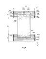
- FIG. 1 is a plan view of the absorbent article according to the embodiment as viewed from the skin surface side.
- FIG. 1 and FIG. 2 are schematic plan views of the absorbent article 1 according to the present embodiment.
- the schematic plan views shown in FIGS. 1 and 2 show an extended state in which the absorbent article 1 is extended to a state in which wrinkles due to shrinkage of an elastic member or the like are not formed in a state where a side joint portion 80 described later is developed.
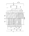
- FIG. 2 schematically shows a region in the front waistline region S1 and a region in the rear waistline region S2 of the absorbent article 1.
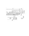
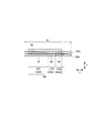
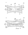
- FIG. 3 is a sectional view taken along the line AA shown in FIG.
- FIG. 4 is a sectional view taken along line BB shown in FIG.
- FIG. 5 is a sectional view taken along the line CC shown in FIG.
- FIG. 6 is a diagram for explaining the absorbent article according to the embodiment.
- FIG. 6 is a view in which a part of the front waistline region S1 and the rear waistline region S2 of the absorbent article 1 is viewed in a state where a side joint portion 80 described later is not deployed.
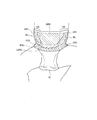
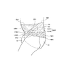
- FIG. 7 and FIG. 8 are diagrams schematically showing a mounted state of the absorbent article according to the embodiment. 7 and 8 indicates a line of the body of the wearer. It should be noted that a central contraction region CER described later is omitted in FIGS. 7 and 8.
- FIG. 9 is a diagram schematically illustrating a transport state at the time of manufacturing the absorbent article according to the embodiment.
- the absorbent article may be of a tape type or a pants type.
- the absorbent article may be a disposable diaper or a shorts type sanitary napkin.
- the absorbent article of the embodiment is a pants-type disposable diaper.
- the absorbent article 1 has a front-rear direction L and a width direction W orthogonal to each other.
- the front-back direction L is defined by a direction extending to the front side of the body and the rear side of the body.
- the front-back direction L is a direction that extends back and forth in the deployed absorbent article 1.
- the absorbent article 1 has a thickness direction T orthogonal to both the front-rear direction L and the width direction W.
- the absorbent article 1 has a front waistline area S1, a rear waistline area S2, and a crotch area S3.
- the front waistline region S1 is a region facing the wearer's front waistline (abdomen).
- the rear waistline region S2 is a region facing the wearer's rear waistline (back).
- the inseam area S3 is an area located at the inseam of the wearer and arranged between the front waist area S1 and the rear waist area S2. Therefore, the crotch region S3 is sandwiched between the front waist region S1 and the rear waist region S2 in the front-rear direction.
- the crotch region S3 may be defined by a region where the leg opening 15 is provided.
- the leg opening 15 is a portion that is recessed inward in the width direction W from the outer edge of the disposable diaper.
- the boundary between the front waistline region S1 and the crotch region S3 may be defined by the front edge of the leg opening 15.
- the boundary between the rear waistline region S2 and the crotch region S3 may be defined by the rear edge of the leg opening 15.
- the absorbent article 1 may include the absorbent main body 10 and the exterior body 50.
- the absorbent main body 10 is arranged at least in the crotch region S3.
- the absorbent main body 10 may extend over the front waistline region S1, the rear waistline region S2, and the crotch region S3. Therefore, the absorbent main body 10 may be disposed over the front exterior body 50A and the rear exterior body 50B.
- the absorbent main body 10 may be configured separately from the front exterior body 50A and the rear exterior body 50B. In this case, the absorbent main body 10 may be joined to the front exterior body 50A and the rear exterior body 50B in the front waistline region S1 and the rear waistline region S2, respectively.
- the absorbent main body 10 has the absorbent core 20.
- the absorbent core 20 may be made of an absorbent material that absorbs liquid.
- the absorbent core 20 may include, for example, pulp (ground pulp) or superabsorbent polymer (SAP), or a mixture thereof.
- the absorbent core 20 may have a region (low basis weight portion) having a basis weight lower than the surroundings in a region overlapping with the preceding continuous shrinkage region FCR described later.
- the absorbent core 20 is arranged at least in the crotch region S3.
- the absorbent core 20 may extend from the front waistline region S1 to the rear waistline region S2 in the front-back direction L.
- the absorbent core 20 may be covered by a core wrap (not shown).
- the core wrap can be made of, for example, a nonwoven fabric or a tissue sheet.
- the absorbent main body 10 may have a top sheet 30 located on the skin side of the absorbent core 20 and a back sheet 40 located on the non-skin side of the absorbent core 20.
- the topsheet 30 is a liquid-permeable sheet.
- the topsheet 30 is made of any sheet-like material having a structure that allows liquid to pass through, such as a nonwoven fabric, a woven fabric, a perforated plastic sheet, or a mesh sheet.
- a nonwoven fabric such as a nonwoven fabric, a woven fabric, a perforated plastic sheet, or a mesh sheet.
- a mesh sheet such as a nonwoven fabric, a woven fabric, a perforated plastic sheet, or a mesh sheet.
- any of natural fibers and chemical fibers can be used.
- the back sheet 40 is a liquid-impermeable sheet.
- a laminated nonwoven fabric mainly composed of a polyethylene sheet, polypropylene or the like, a breathable resin film, a sheet in which a breathable resin film is bonded to a nonwoven fabric such as spun bond or spunlace, or the like can be used.
- the exterior body 50 is a member arranged in the waist area.
- the exterior body 50 may be referred to as a waist member.
- the exterior body 50 has a front exterior body 50A and a rear exterior body 50B.
- the front exterior body 50A is arranged in the front waistline area S1.
- the rear exterior body 50B is arranged in the rear waistline area S2.
- the front exterior body 50A includes an exterior sheet 52 (front exterior sheet 52A), a side top sheet 54 (front side top sheet 54A), an elastic sheet 56, And a front elastic member 60.
- the front exterior sheet 52A may be arranged on the non-skin side than the absorbent main body 10.
- the front exterior sheet 52A can be made of, for example, a nonwoven fabric.
- the outer edge of the front exterior sheet 52A in the front-rear direction L may be at the same position as the outer edge of the front side top sheet 54A in the front-rear direction L.
- the outer end of the front exterior sheet 52A in the front-rear direction L may be folded toward the non-skin side.
- the front side top sheet 54A may be arranged on the skin side relative to the front exterior sheet 52A.
- the front side top sheet 54A can be made of, for example, a nonwoven fabric.
- the front exterior sheet 52A and the front side top sheet 54A may be joined by, for example, a sonic seal in a region where the front elastic member 60 is not disposed (a low contraction region LER described later).
- the elastic sheet 56 may be arranged on the skin side of the front side top sheet 54A.
- the elastic sheet 56 is a sheet-like elastic member.
- the elastic sheet 56 has elasticity at least in the width direction W. Therefore, the elastic sheet has shrinkage in the width direction W.
- the elastic sheet 56 may have elasticity (contractibility) in the front-rear direction L.
- the elastic sheet 56 is disposed so as to overlap the front elastic member 60 in the thickness direction T.
- the end of the stretchable sheet 56 in the width direction W may be fixed to the front side top sheet 54A by the side joint portion 80 in a state where the stretchable sheet 56 extends in the width direction W.
- the stretchable sheet 56 is stretched in the width direction W by an adhesive portion (not shown) such as a hot-melt adhesive (HMA) or a sonic seal. It may be fixed to the top sheet 54A.
- HMA hot-melt adhesive
- the elastic sheet 56 may be made of, for example, an elastic resin film, an elastic nonwoven fabric, or a combination thereof.
- the front elastic member 60 is a thread-like or belt-like elastic member.
- the front elastic member 60 has contractility. In detail, since the front elastic member 60 has elasticity, it is contractible by being arranged in an extended state.
- the front elastic member 60 is arranged in the front waistline region S1 in a state of extending in the width direction W.
- the front elastic member 60 may be disposed between the front exterior sheet 52A and the front side top sheet 54A in the thickness direction T.
- a plurality of front elastic members 60 may be arranged side by side at intervals in the front-rear direction L. As shown in FIGS. 3 to 5, in the present embodiment, the front elastic member 60 is disposed so as to overlap with the elastic sheet 56 in the thickness direction T in a state where the front elastic member 60 extends in the width direction W.
- the front elastic member 60 may include a first front elastic member 61, a second front elastic member 62, a third front elastic member 63, and a central elastic member 65.
- the first front elastic member 61 is disposed outside the central region CR (first low contraction region LER1) described later in the width direction W, and is disposed outside the third front elastic member 63 in the front-rear direction L.
- the second front elastic member 62 is an elastic member that is disposed outside the second low contraction region LER2 described later in the width direction W, and is disposed inside the third front elastic member 63 in the front-rear direction L. is there.
- the third front elastic member 63 is an elastic member that continuously extends from one side to the other side in the width direction W of the front waistline region S1 (the front exterior body 50A) in the width direction W.
- the central elastic member 65 is an elastic member arranged in a central region CR described later.
- the first front elastic member 61 may extend inward in the width direction W from both sides in the width direction W of the front waistline region S1 (the front exterior body 50A). The first front elastic member 61 does not continuously extend from one side in the width direction W of the front waistline region S1 to the other side in the width direction W.
- the first front elastic member 61 may be fixed (adhered) by the side joint portion 80 on the side in the width direction W of the front waistline region S1.
- the inner end of the first front elastic member 61 in the width direction W may be fixed (adhered) to the front exterior sheet 52A by an adhesive portion 85 such as a hot melt adhesive (HMA), for example.
- the length of the first front elastic member 61 in the width direction W may be shorter as going outward in the front-rear direction L.
- the first front elastic member 61 of the present embodiment is constituted by first front elastic members 611 to 619.
- the length in the width direction W of the first front elastic member 611 and the first front elastic member 612 is the same.
- the length in the width direction W of the first front elastic members 612 to 619 decreases as going outward in the front-rear direction L. Accordingly, the length of the arbitrary first front elastic member 61 included in the first front elastic member 61 in the width direction W is the first front elastic member located outside the arbitrary first front elastic member 61 in the front-rear direction L. It is longer than the length of the member 61.
- the second front elastic member 62 may extend inward in the width direction W from both sides in the width direction W of the front waistline region S1 (the front exterior body 50A).
- the second front elastic member 62 does not continuously extend from one side to the other side in the width direction W of the front waistline region S1 in the width direction W.
- the second front elastic member 62 may be fixed (adhered) by the side joint portion 80 on the side in the width direction W of the front waistline region S1.
- the inner end of the second front elastic member 62 in the width direction W may be fixed (adhered) to the front exterior sheet 52A by an adhesive portion 85.
- the length in the width direction W of each second front elastic member 62 may be the same or may be different.
- the second front elastic member 62 of the present embodiment is configured by second front elastic members 621 to 624.
- the third front elastic member 63 is disposed between the first front elastic member 61 and the second front elastic member 62 in the front-rear direction L.
- the third front elastic member 63 may be fixed (adhered) by the side joint portion 80 on both sides in the width direction W of the front waistline region S1.
- the third front elastic member 63 of the present embodiment includes third front elastic members 631 and 632.
- the center elastic member 65 is disposed between the first front elastic member 61 on one side and the first front elastic member 61 on the other side in the width direction W.
- the center elastic member 65 is arranged apart from the first front elastic member 61 in the width direction W.
- the center elastic member 65 may be formed of the same member as the first front elastic member 61 when it is provided by cutting the first front elastic member 61, as described later.
- the central elastic member 65 may be configured by a member different from the first front elastic member 61.
- the rear exterior body 50B includes an exterior sheet 52 (rear exterior sheet 52B), a side top sheet 54 (rear side top sheet 54B), and a rear elastic member 70. , May be included.
- the rear exterior sheet 52B may be arranged on the non-skin side than the absorbent body 10.
- the rear exterior sheet 52B can be made of, for example, a nonwoven fabric.
- the outer end of the rear exterior sheet 52B in the front-rear direction L may be folded toward the non-skin side. Therefore, at the end of the rear exterior body 50B in the front-rear direction L, the rear exterior sheet 52B may sandwich the rear side top sheet 54B in the thickness direction T.
- the rear side top sheet 54B may be arranged on the skin side relative to the rear exterior sheet 52B.
- the rear side top sheet 54B can be made of, for example, a nonwoven fabric.
- the rear elastic member 70 is a thread-like or band-like elastic member.
- the rear elastic member 70 has a contractibility similarly to the front elastic member 60.
- the rear elastic member 70 is arranged in the rear waistline region S2 in a state of extending in the width direction W.
- the rear elastic member 70 may be disposed between the rear exterior sheet 52B and the rear side top sheet 54B in the thickness direction T.
- the rear elastic members 70 may be arranged side by side in the front-rear direction L.
- the rear elastic member 70 may include a first rear elastic member 71 and a second rear elastic member 72.
- the first rear elastic member 71 is an elastic member disposed in a rear continuous contraction region RCR described later.
- the second rear elastic member 72 is an elastic member disposed in a rear contraction region RR described later.
- the first rear elastic member 71 extends continuously from one side in the width direction W of the rear waistline region S2 to the other side in the width direction W.
- the first rear elastic member 71 may be fixed (adhered) by the side joint portions 80 on both sides in the width direction W of the rear waistline region S2.
- the first rear elastic member 71 of the present embodiment includes first rear elastic members 711 to 717 and first rear elastic members 71a to 71c.
- the first rear elastic members 711 to 717 are elastic members arranged in a first rear continuous contraction region RCR1 described later.
- the first rear elastic members 71a to 71c are elastic members arranged in a second rear continuous contraction region RCR2 described later.
- the first rear elastic members 711 to 717 are not adjacent to the front continuous contraction region FCR in the width direction W, whereas the first rear elastic members 71a to 71c are adjacent to the front continuous contraction region FCR and the width direction W. Are adjacent to each other.
- the second rear elastic member 72 may extend inward in the width direction W from both sides in the width direction W of the rear waistline region S2 (the rear exterior body 50B).
- the second rear elastic member 72 does not continuously extend from one side in the width direction W of the rear waistline region S2 to the other side in the width direction W.
- the second rear elastic member 72 is disposed inside the first rear elastic member 71 in the front-rear direction L.
- the second rear elastic member 72 may be fixed (adhered) by the side joint portion 80 on the side in the width direction W of the rear waistline region S2.
- the inner end of the second rear elastic member 72 in the width direction W may be fixed (adhered) to the rear exterior sheet 52B by an adhesive portion 85.
- the length in the width direction W of each second rear elastic member 72 may be the same or may be different.
- the second rear elastic member 72 of the present embodiment is configured by the second rear elastic members 721 to 724.
- the side joint portion 80 joins an outer portion in the width direction W of the front exterior body 50A (the front waist region S1) and an outer portion in the width direction W of the rear exterior body 50B (the rear waist region S2).
- the side joint 80 may extend along the front-rear direction L.
- the outer edge of the side joint portion 80 in the front-rear direction L may be at the same position as the outer edge of the front exterior body 50A in the front-rear direction L in the front-rear direction L, or may be at a different position.
- the outer edge of the side joint portion 80 in the front-rear direction L may be defined as the outer edge of the front exterior body 50A in the front-rear direction L.
- the inner edge of the side joint portion 80 in the front-rear direction L may be at the same position as the inner edge of the front exterior body 50A in the front-rear direction L in the front-rear direction L, or may be at a different position.
- the inner edge of the side joint portion 80 in the front-rear direction L may be defined as the inner edge of the front exterior body 50A in the front-rear direction L.
- the front waistline region S1 (the front exterior body 50A) extends in the width direction W of the front waistline region S1 (the front exterior body 50A) based on the center in the width direction W in the extended state of the front exterior body 50A.
- the front waistline region S1 (the front exterior body 50A) has a contraction region having a contractibility and a low contraction region in which the contraction force is lower than that of the contraction region.
- the low shrinkage region may be arranged so as to straddle the center of the front exterior body 50A in the width direction W.
- the low shrinkage region extends from the center in the width direction W to the outside in the width direction W.
- the shrink region has shrinkage due to the front elastic member 60.
- the contraction region is located outside the low contraction region in the width direction W.
- the front waistline region S1 (front exterior body 50A) includes a first front contraction region ER1, a central region CR (first low contraction region LER1 and a central contraction region CER), a front continuous contraction region FCR, It has a second pre-shrink region ER2 and a second low-shrink region LER2.
- the contraction region has a pre-continuous contraction region FCR, a first pre-contraction region ER1, and a second pre-contraction region ER2, and the low-contraction region includes a first low-contraction region LER1, a second low-contraction region LER2, Having.
- the first front contraction region ER1 is contractible by the front elastic member 60 (first front elastic member 61), and extends from both sides of the front waistline region S1 in the width direction W in the width direction W. These are two regions extending inward. Therefore, the first pre-shrink region ER1 is arranged outside the center region CR in the width direction W. That is, the first pre-shrink region ER1 is arranged outside the first low-shrink region LER1 in the width direction W. In the present embodiment, the first front contraction region ER1 is located outside the front continuous contraction region FCR in the front-rear direction L. Therefore, the first pre-contraction region ER1 is arranged outside the second pre-contraction region ER2 in the front-rear direction L.
- the first front contraction region ER1 is a region contracted by the first front elastic members 611 to 619. Therefore, the first front elastic members 611 to 619 are arranged in the first front contraction region ER1. Further, in the present embodiment, the first pre-shrink region ER1 may have shrinkability by the stretchable sheet 56.
- the inner edge in the width direction of the first pre-contraction region ER1 may be located outside in the width direction W as going outward in the front-rear direction L. At least a part of the inner edge of the first pre-contraction region ER1 may be located inside the outer edge of the absorbent main body 10 in the width direction W. In the embodiment, a region constituting the outside of the first front contraction region ER1 in the front-rear direction L is located outside the outer edge of the absorbent main body 10 in the width direction W. On the other hand, a region that forms the inside of the first front contraction region ER1 in the front-rear direction L is located inside the outer edge of the absorbent main body 10 in the width direction W.
- the length in the width direction of the outer edge of the first front contraction region ER1 in the front-rear direction L is at least twice the length of the width direction W of the inner edge in the front-rear direction L of the first front contraction region ER1.
- the (first part) first contraction region ER ⁇ b> 1 may be disposed so as to overlap the absorbent main body 10 in the thickness direction T.
- the (part of) the first pre-shrink region ER1 may be arranged so as to overlap the absorbent core 20 in the thickness direction T. Since the absorbent core 20 can be brought into close contact with the wearer's body by the contraction of the first pre-contraction region ER1, leakage of excrement can be suppressed.
- the maximum width in the width direction W of the region where the first pre-shrink region ER1 and the absorbent core 20 overlap may be 10 mm or less. Thereby, the contraction of the absorbent core 20 in the width direction W can be suppressed, and the absorption area of the absorbent core 20 can be secured.
- the first pre-shrink region ER ⁇ b> 1 may be arranged so as not to overlap the absorbent core 20 in the thickness direction T.
- the center region CR is a region arranged between the two first pre-contraction regions ER1 in the width direction W. At least a part of the central region CR may be arranged outside the absorbent main body 10 in the front-rear direction L. As shown in FIG. 2 and the like, in the present embodiment, the central region CR has a first low contraction region LER1 and a central contraction region CER.
- the first low contraction region LER1 is a region where the contraction force is lower than that of the first pre-contraction region ER1.
- strong tightening by the front elastic member 60 is reduced. Therefore, (the first low-shrinkage region LER1 of) the front exterior body 50A arranged in the front waistline region S1 can cover the body according to the shape of the wearer's body, and suppresses the deterioration of the wearing feeling of the wearer. it can.
- the first low contraction region LER1 can reduce the contraction force by using, for example, the first method or the second method.
- the contraction region may be reduced by not disposing the front elastic member 60 in the extended state in the first low contraction region LER1.
- the bonding portion 85 for fixing the front elastic member 60 is not disposed, and the bonding portion 85 and the side bonding portion are extended in a state where the front elastic member 60 is extended in the width direction W. Fix by 80.
- the front elastic member 60 overlaps (the region corresponding to) the first low contraction region LER1 in the thickness direction T, the front elastic member 60 is cut on the first low contraction region LER1. As a result, the cut front elastic member 60 contracts, and the front elastic member 60 is not arranged in the extended state in the first low contraction region LER1.
- the front elastic member 60 having a contracting property (that is, in an extended state) is not arranged in the first low contraction region LER1, the contraction force in the first low contraction region LER1 is easily controlled.
- the front elastic member 60 may have a fixed portion and a non-fixed portion.
- the fixed portion is a portion that is fixed in the front waistline region S1 in an extended state.
- the fixing portion may be a portion fixed by the bonding portion 85 and the side joint portion 80.
- the fixed portion may be a first front elastic member 61 disposed in the first front contraction region ER1, and a central elastic member 65 disposed in the center contraction region CER.
- the non-fixed portion is a portion that is not fixed in the front waistline region S1 and exists in a natural state.
- the non-fixed portion is a portion disposed between the bonding portions 85 before the cutting of the front elastic member 60, a portion where the front elastic member 60 is contracted by cutting, and connected to the fixed portion of the front elastic member 60. .
- the non-fixed portion may be arranged on the front exterior body 50A via the bonding portion 85 in a contracted state (natural state).
- the non-fixed portion may overlap the first low contraction region LER1 in the thickness direction T.
- the non-fixed portion of the front elastic member 60 may overlap the first front contraction region ER1 in the thickness direction T due to transportation during manufacturing or the like.
- the front elastic member 60 When the contraction force is reduced by the first method, the front elastic member 60 is not fixed to the first low contraction region LER1 in a stretched state. For this reason, the first low-shrinkage region LER1 does not overlap in the thickness direction T with the thread-like or band-like front elastic member 60 in the extended state.
- the contraction force of the front elastic member 60 may be reduced by cutting (cutting) the front elastic member 60 fixed to the first low contraction region LER1 at a plurality of locations. In this case, the contraction force of the front elastic member 60 is reduced even if the front elastic member 60 is fixed to the first low contraction region LER1 in an extended state.
- each front elastic member 60 after extending each front elastic member 60 from one first pre-contraction area ER1 to the other first pre-contraction area ER1 over the first low-contraction area LER1, the above-mentioned first method or the first Each of the front elastic members 60 may be cut by the second method. Thereby, the same front elastic member 60 can be arranged in the two first contraction regions ER1. Therefore, it is possible to arrange the front elastic members 60 having the same expansion ratio in one first front contraction region ER1 and the other first front contraction region ER1.
- each front elastic member 60 may be cut by the first method or the second method described above. Thereby, the same front elastic member 60 can be arranged in the two first contraction regions ER1 and the central contraction region CER. Since the separate front elastic members 60 need not be arranged in each of the plurality of contraction regions (the two first contraction regions ER1 and the central contraction region CER), a reduction in production efficiency can be suppressed.
- the range of the first low contraction region LER1 (and the first previous contraction region ER1) may be defined by providing the first low contraction region by the above method.
- the “contraction force” of each region may be measured by the following method.
- a test piece to be measured is created. Both ends of the test piece are clamped by a chuck (clamping tool) of a tensile tester. At this time, the distance between the chucks is set to 50 mm.
- the other of the chucks is moved so as to change the distance between the chucks.
- the moving speed of the chuck at this time is 300 mm / min.
- the stress applied to the chuck is measured, and the stress (N) obtained in a state of 60% (constant width) from the expanded state is defined as “contraction force”.
- the first low contraction region LER1 is located outside the front continuous contraction region FCR in the front-rear direction L. Therefore, the first low contraction region LER1 is disposed outside the second low contraction region LER2 in the front-rear direction L.
- the first low shrinkage area LER1 may reach the outer end of the front exterior body 50A (front waist area S1) in the front-rear direction L. Therefore, the first low-shrinkage region LER1 may be arranged so as to extend to the outer end in the front-rear direction L of the front exterior body 50A (the front waistline region S1). As shown in FIGS. 7 and 8, the stomach bulges upward (outward in the front-rear direction) from the recess at the lower end of the abdomen, and therefore, the waist length of the stomach at the outer end in the front-rear direction L of the front exterior body 50A. The longer the waist area, the easier the stomach is tightened.
- the first low-shrinkage region LER1 is arranged so as to extend to the outer end portion in the front-rear direction L of the front exterior body 50A, the first low-shrinkage region LER1 can reduce the tightening of the part where the stomach is easily tightened, and can be worn. It is possible to suppress deterioration of the wearing feeling of the user.
- the outer end of the front exterior body 50A in the front-rear direction L is a region extending up to 10 mm from the outer edge of the front exterior body 50A in the front-rear direction L.
- One front elastic member 60 extending in the width direction W may be disposed at the outer end of the front exterior body 50A in the front-rear direction L, and may not be disposed.
- the front elastic member 60 may extend from one side of the front exterior body 50A to the other side in the width direction W.
- the first low contraction region LER1 may be arranged between the central contraction region CER and the first front contraction region ER1 in the width direction W.
- the maximum length of the first low contraction region LER1 in the width direction W may be longer than the length of the central contraction region CER in the width direction W.
- the outer edge in the width direction W of the first low-shrinkage region LER1 is arranged in the outer region OR outside the absorbent body 10 in the front-rear direction L. Outside the absorbent body 10 in the front-rear direction L, a part of the outer edge of the first low-shrinkage region LER1 may be arranged in the outer region OR, and the entire outer edge of the first low-shrinkage region LER1 is entirely outside the OR region OR. May be arranged. As shown in FIG. 7, the swelling of the stomach spreads outward in the width direction W from the recess at the lower end of the wearer's abdomen upward (outward in the front-rear direction).
- the low contraction region is disposed at a position corresponding to the shape of the stomach bulge. easy.
- the first front contraction region ER1 is located outside the first low contraction region LER1 in the width direction, the contraction of the first front contraction region ER1 causes the front exterior body 50A to be in close contact with the wearer's body.
- the length from the center in the width direction W of the front exterior body 50A to the outer edge in the width direction W of the first low shrinkage region LER1 is the outermost in the front-rear direction L of the first low shrinkage region LER1. , Is up.
- FIG. 7 it is possible to reduce not only the tightening not only at the center of the abdomen in the width direction but also at the side of the abdomen on the upper side of the abdomen, thereby suppressing deterioration of the wearing feeling of the wearer. it can.
- One outer edge of the first low contraction region LER1 in the width direction W may be located outside the width direction W as it goes outward in the front-rear direction L. Therefore, the outer edge of the first low-shrinkage region LER1 in the width direction W may be located inside the width direction W as it goes inward in the front-rear direction L.
- both outer edges in the width direction W of the first low shrinkage region LER1 may be located outside in the width direction W toward the outside in the front-rear direction L. Therefore, both outer edges in the width direction W of the first low-shrinkage region LER1 may be located inside the width direction W toward the inside in the front-rear direction L. As shown in FIG.
- the swelling of the stomach spreads outward in the width direction W from the dent at the lower end of the abdomen toward the upper side (outward in the front-rear direction).
- the first low-shrinkage region LER1 is arranged in a region corresponding to the shape of the stomach bulge by being located outside in the width direction W. be able to. Since the first low-shrinkage region LER1 corresponds to the shape of the belly, it is possible to prevent the first low-shrinkage region LER1 from being too closely attached to the stomach bulge, and to suppress deterioration of the wearing feeling of the wearer.
- At least a part of the outer edge of the first low-shrinkage region LER1 may be located outside the outer edge of the absorbent main body 10 in the width direction W.
- a region constituting the outside of the first low contraction region LER1 in the front-rear direction L is located outside the outer edge of the absorbent main body 10 in the width direction W. Accordingly, the first low contraction region LER1 can be arranged in a region including a stomach bulge even outside the outer edge of the absorbent main body 10 in the width direction W.
- the first low-shrinkage region LER1 corresponds to the shape of the belly, it is possible to prevent the first low-shrinkage region LER1 from being too closely attached to the stomach bulge, and to suppress deterioration of the wearing feeling of the wearer.
- the region constituting the inside of the first low contraction region LER1 in the front-rear direction L may be located inside the outer edge of the absorbent main body 10 in the width direction W. Therefore, the upper side (that is, the outer edge of the first low-shrinkage area LER1 in the front-rear direction L) of the first low-shrinkage area LER1 is larger than the lower side (that is, the inner edge of the first low-shrinkage area LER1 in the front-rear direction L). May have a long inverted trapezoidal shape.
- the absorbent main body 10 overlapping the first pre-contraction region ER1 is pulled outward in the width direction W. Therefore, since the absorbent main body 10 can be brought into close contact with the body of the wearer, leakage of excrement can be suppressed.
- the length in the width direction of the outer edge in the front-rear direction L of the first low contraction region LER1 is at least twice the length in the width direction W of the inner edge in the front-rear direction L of the first low contraction region LER1. May be.
- the first low-shrinkage region LER1 can be easily made to correspond to the shape of the belly bulge spreading outward in the width direction.
- the first low-shrinkage region LER1 corresponds to the shape of the belly, it is possible to prevent the first low-shrinkage region LER1 from being too closely attached to the stomach bulge, and to suppress deterioration of the wearing feeling of the wearer.
- the maximum length of the first low shrinkage region LER1 in the width direction W may be longer than the maximum length of the absorbent main body 10 in the width direction W.
- the first low contraction region LER1 since the contraction force of the front elastic member 60 is reduced, the contraction of the absorbent main body 10 in the width direction W can be suppressed.
- the absorbent main body 10 can be brought into close contact with the body widely, and leakage of excrement can be suppressed.
- the length in the width direction W of the first low-shrinkage region LER1 outside the outer edge in the front-rear direction L of the absorbent article 1 in the front-rear direction L is equal to the length of the front exterior body 50A (front waistline). It may be 1 / or more of the length in the width direction W of the region S1).
- the first low-shrinkage region LER ⁇ b> 1 may be arranged across the outer edge of the absorbent main body 10 in the front-rear direction. Therefore, (a part of) the first low contraction region LER ⁇ b> 1 may be arranged so as to overlap the absorbent main body 10 in the thickness direction T.
- the swelling of the stomach continues from the dent at the lower end of the abdomen to the upper side (outer side in the front-rear direction). Therefore, when the absorbent article 1 is worn, the swelling of the stomach also exists above the absorbent main body 10 (outside in the front-rear direction L).
- the first low-shrinkage region LER1 is disposed across the outer edge of the absorbent main body 10, the first low-shrinkage region is also provided above the absorbent main body 10 in a region corresponding to the shape of the belly bulge. LER1 can be arranged. Since the first low-shrinkage region LER1 corresponds to the shape of the belly, it is possible to suppress the front exterior body 50A from being too close to the stomach bulge, and to suppress the deterioration of the wearing feeling of the wearer. In another embodiment, the first low-shrinkage region LER1 may be arranged so as not to overlap the absorbent body 10 in the thickness direction T.
- the first low shrinkage region LER1 may be arranged so as to overlap with the absorbing core 20 in the thickness direction T (that is, in a region overlapping with the absorbing core 20).
- the first low shrinkage region LER1 since the shrinking force of the front elastic member 60 is reduced, it is possible to suppress the absorption core 20 from shrinking in the width direction W, and to secure an absorption area of the absorption core 20. Therefore, leakage of excrement can be suppressed.
- the minimum length of the first low-shrinkage region LER1 in the width direction W may be shorter than the length of the absorbent core 20 in the width direction W.
- the first pre-shrinkage region ER1 located outside the first low-shrinkage region LER1 in the width direction W is smaller than the absorption core. 20 in the thickness direction T. Therefore, while the end of the absorbent core 20 in the width direction W is in close contact with the body due to the contraction of the first pre-shrink region ER1, the center of the absorbent core 20 in the width direction W is widely adhered to the body by the first low contraction region LER1. And the leakage of excrement can be suppressed.
- the first low-shrinkage region LER1 may be arranged so as not to overlap the absorbent core 20 in the thickness direction T.
- the length of the first low shrinkage region LER1 in the front-rear direction L may be 50% or more of the length of the side joining portion 80 in the front-rear direction L. Since the first low contraction region LER1 is 50% or more of the length in the front-rear direction of the side joint portion 80, the first low contraction region LER1 is widely arranged in the front-rear direction L at a position corresponding to the shape of the stomach bulge. be able to. Thereby, deterioration of the wearing feeling of the wearer can be suppressed.
- the first low-shrinkage region LER ⁇ b> 1 inside the outer region OR in the width direction W starts from the outer edge of the side joint portion 80 in the front-rear direction L and extends in the front-rear direction of the side joint portion 80. It may be arranged in a region from 0% to 60% of the length of L (hereinafter, 0-60% region).
- the 0-60% region On the inner side in the width direction W than the outer region OR, the 0-60% region generally corresponds to the stomach bulge of the wearer.
- the first low contraction region LER1 corresponds to the shape of the belly, it is possible to prevent the first low contraction region LER1 from being too close to the stomach bulge, and to further suppress the deterioration of the wearer's feeling of wearing.
- the first low-shrinkage region LER ⁇ b> 1 has a length from 0% to 40% of the length of the side joint portion 80 in the front-rear direction L starting from the outer edge of the side joint portion 80 in the front-rear direction L. It may be arranged in an area (hereinafter, 0-40% area).
- the 0-40% region generally corresponds to the stomach bulge of the wearer. For this reason, since the first low contraction region LER1 corresponds to the shape of the belly, it is possible to prevent the first low contraction region LER1 from being too close to the stomach bulge, and to further suppress the deterioration of the wearer's feeling of wearing.
- a first pre-shrink region ER1 may be arranged.
- the 40-60% region is a portion where the shape of the stomach bulge is unlikely to change due to a change in the movement of the wearer (for example, a change from a standing posture to a sitting posture (from a sitting posture to a standing posture)). Therefore, by bringing the front exterior body 50A into close contact with the 40-60% region by the first pre-shrinkage region ER1, the front exterior body 50A is unlikely to slip and fall, and the front exterior body 50A can be kept held.
- the first low shrinkage area LER1 may be arranged in an area overlapping the elastic sheet 56 in the thickness direction T as described later. Since the stretchable sheet 56 faces the skin of the wearer on the surface, it can apply pressure on the surface. Thereby, the first low contraction region LER1 can be brought into close contact with the body by contraction of the stretchable sheet 56 while suppressing the occurrence of local tightening, and the contraction force of the front elastic member 60 is reduced. It is possible to suppress the front exterior body 50A from being shifted from the first low shrinkage area LER1.
- the central contraction region CER is a region having higher contractility than the first low contraction region LER1.
- the central contraction region CER is a region contracted by the central elastic member 65. Therefore, the central elastic member 65 is disposed in the central contraction region CER.
- the central contraction region CER may have contractibility by the elastic sheet 56.
- At least a part of the central contraction region CER is disposed outside the absorbent main body 10 in the front-rear direction L. Since the front exterior body 50A is contracted by the contraction of the central contraction region CER, the rigidity of the central contraction region CER is higher than the rigidity of the first low contraction region LER1. By arranging at least a part of the central contraction region CER outside the absorbent main body 10 in the front-rear direction L, the central contraction region CER in which the front exterior body 50A is unlikely to buckle due to the high rigidity can be combined with the absorbent main body 10. It can exist in the non-overlapping central region CR.
- the central contraction region CER due to the contraction of the central contraction region CER, the central contraction region CER can be brought into close contact with the body, and the front exterior body 50A can easily cover the body of the wearer.
- the absorbent article 1 can reduce the wear of the front exterior body 50A by the central contraction region CER while suppressing the wearer's feeling of wearing by the first low contraction region. This makes it easier for the absorbent article 1 to continue to cover the wearer's body while suppressing deterioration of the wearing feeling.
- the central contraction region CER may be disposed across a center line C1 that extends through the center CO of the absorbent core 20 in the width direction W and extends in the front-rear direction L.
- the central contraction region CER is arranged apart from the first low contraction region LER1 in the width direction W. Therefore, in the width direction W, the first low contraction region LER1 exists between the central contraction region CER and the first low contraction region LER1.
- the rigidity is increased by the rigidity of the absorbent main body with the outer edge of the absorbent main body as a boundary. There is a difference. Since the force tends to concentrate on the place having the difference in rigidity, the outer body 50 (the first low-shrinkage region LER1 of the outer body 50) is easily bent from the outer edge of the absorbent main body 10 having the large difference in rigidity.
- the exterior body 50 may be bent inward by bending toward the skin side of the absorbent main body 10, or may be bent outward by bending toward the non-skin side of the absorbent main body 10.
- the central contraction region CER may be arranged so as to straddle the outer edge of the absorbent main body 10 in the front-rear direction L in the thickness direction T. Therefore, the central contraction region CER may be arranged so as to overlap the absorbent main body 10 in the thickness direction T. Since the rigidity around the outer edge in the front-rear direction L of the absorbent main body 10 can be increased by the central contraction region CER having high rigidity, the exterior with the outer edge in the front-rear direction L of the absorbent main body 10 as a base point.
- the bending of (the first low contraction region LER1) of the body 50 can be suppressed. As a result, it is possible to reduce that the exterior body 50 is bent, and it is possible to easily cover the wearer's body while suppressing deterioration of the wearing feeling.
- the center contraction region CER may be arranged in a region that does not overlap with the absorbent core 20 in the thickness direction T. Even if the central contraction region CER contracts, the contraction of the absorbent core 20 together can be suppressed. Therefore, the absorption area of the absorption core 20 can be secured, and leakage of excrement can be further suppressed.
- the length of the central contraction region CER in the width direction W may be longer than 1 / of the length of the absorbent core 20 in the width direction W. Thereby, it is easy to obtain the effect of securing the rigidity of the central region CR, and it is possible to reduce that the exterior body 50 is bent.
- the rigidity of the outer portion of the exterior body 50 located outside the outer edge of the absorbent main body 10 in the width direction W is not increased by the absorbent main body 10.
- the central contraction region CER when the central contraction region CER is arranged on the outer portion of the outer body 50, the outer portion of the outer body 50 shrinks more than necessary, so that the wearer can easily feel the tightening by the outer body 50 and the feeling of wearing deteriorates. there's a possibility that. Therefore, the outer edge of the central contraction region CER in the width direction W may be located inside the outer edge of the absorbent main body 10 in the width direction W. As a result, the central contraction region CER is not arranged in the outer portion of the front exterior body 50A, and it is possible to suppress deterioration of the wearing feeling.
- the central contraction region CER may extend in the front-rear direction L, and may reach the outer end of the front exterior body 50A (front waist region S1) in the front-rear direction L. Accordingly, since the central contraction region CER having high rigidity exists, it is possible to suppress the front exterior body 50A from being bent from the outer end in the front-rear direction L of the front exterior body 50A.
- the central contraction region CER is located before and after a region extending from the outer edge of the side joint portion 80 in the front-rear direction L to 20% of the length of the side joint portion 80 in the front-rear direction L (hereinafter, upper portion of the central region CR). It may be arranged only inside the direction L. Therefore, the central contraction region CER does not need to be disposed above the central region CR.
- the length of the upper part of the central region CR in the front-rear direction L may be, for example, a region from the outer edge of the side joint part 80 in the front-rear direction L to 10 mm to 15 mm.
- the rigidity of the upper portion of the central region CR can be kept low, and deterioration of the feel of the wearer can be suppressed.
- the upper part of the central region CR is a region corresponding to the navel of the wearer. Since the periphery of the wearer's navel is a sensitive part, the presence of a highly rigid part may cause the wearer to feel uncomfortable with the skin. By keeping the rigidity low in the upper part of the central region CR, the wearer does not have an uncomfortable feeling on the skin, and it is possible to suppress deterioration of the wearing feeling.
- the extension ratio of the central elastic member 65 arranged in the central contraction region CER may be 2 times or more. Due to the contraction of the central elastic member 65, members constituting the front exterior body 50A (for example, the front exterior sheet 52A, the front side top sheet 54A, the elastic sheet 56) gather, and the rigidity of the central contraction region CER described later increases. Thereby, it is possible to make it difficult for the front exterior body 50A to buckle.
- the second front contraction region ER2 has contractibility due to the front elastic member 60 (second front elastic member 62).
- the second front contraction region ER2 is a region contracted by the second front elastic members 621 to 624. Therefore, the second front elastic members 621 to 624 are arranged in the second front contraction region ER2. Further, in the present embodiment, the second pre-shrink region ER2 may be contractible by the stretch sheet 56.
- the second front contraction region ER2 is two contraction regions extending inward in the width direction W from both sides in the width direction W of the front waistline region S1.
- the second pre-shrink region ER2 is arranged outside the second low-shrink region LER2 in the width direction W.
- the second pre-contraction region ER2 is located on the inner side in the front-rear direction L than the pre-continuous contraction region FCR. Therefore, the second pre-contraction region ER2 is disposed inside the first pre-contraction region ER1 in the front-rear direction L.
- the first front contraction region ER1 is located outside the first low contraction region LER1 in the width direction W
- the second front contraction region ER2 is located outside the second low contraction region LER2 in the width direction W.
- the front continuous contraction region FCR is a region extending from one side in the width direction W of the front exterior body 50A (the front waistline region S1) to the other side.
- the front continuous contraction region FCR has contractibility due to the front elastic member 60 (the third front elastic member 63).
- the front continuous contraction region FCR is a region contracted by the third front elastic members 631 and 632, and is a region where the third front elastic members 631 and 632 are arranged. Further, in the present embodiment, the front continuous contraction region FCR has contractibility due to the elastic sheet 56.
- the front continuous contraction region FCR is disposed between the first front contraction region ER1 and the second front contraction region ER2 in the front-rear direction L. Further, the front continuous contraction region FCR is disposed between the first low contraction region LER1 and the second low contraction region LER2 in the front-back direction L.
- the outer edge of the front continuous contraction region FCR in the front-rear direction L is defined by the first front elastic member 61 arranged in the first front contraction region ER1. Specifically, the outer edge of the front continuous contraction region FCR in the front-rear direction L is a region inside the first front elastic member 619 located at the innermost side in the front-rear direction L among the first front elastic members 61. . Therefore, the front continuous contraction region FCR is also located outside the third front elastic member 631 in the front-rear direction L.
- the inner edge of the front continuous contraction region FCR in the front-rear direction L is defined by the second front elastic member 62 arranged in the second front contraction region ER2.
- the outer edge of the front continuous contraction region FCR in the front-rear direction L is a region outside the second front elastic member 621 located in the front-rear direction L among the second front elastic members 62. . Therefore, the front continuous contraction region FCR is also located inside the third front elastic member 632 in the front-rear direction L.
- the front continuous contraction region FCR is arranged in a region from 60% to 80% of the length of the side connection portion 80 in the front-rear direction L, starting from the outer edge of the side connection portion 80 in the front-rear direction L. May be.
- the region from 60% to 80% of the length in the front-rear direction L of the side joint portion 80, starting from the outer edge of the side joint portion 80, generally corresponds to the recess at the lower end of the abdomen of the wearer.
- the front exterior body 50A from slipping down to the crotch side, and it is easy to keep covering the wearer's body.
- the portion where the stomach bulges above the dent at the lower end of the abdomen is made to correspond to the first low contraction region LER1.
- the absorbent article 1 does not excessively adhere to a portion where the belly above the dent at the lower end of the abdomen bulges, and it is possible to suppress deterioration of the wearing feeling of the wearer.
- the front continuous shrinkage region FCR may be arranged, for example, in the region of 50 mm to 65 mm from the outer edge of the side joint portion 80 in the front-rear direction L in the case of the M-size absorbent article 1.
- the pre-continuous shrinkage region FCR may be arranged in a region of 60 mm to 75 mm from the outer edge of the side joint portion 80 in the front-rear direction L.
- the pre-continuous shrinkage region FCR may be arranged in a region overlapping with the absorbent core 20 in the thickness direction T. Since the absorbent core 20 can be brought into close contact with the wearer's body by the contraction of the front continuous contraction region FCR, leakage of excrement can be suppressed.
- the absorbent core 20 may have a low basis weight portion having a basis weight lower than the surroundings in a region overlapping with the preceding continuous shrinkage region FCR in the thickness direction T. Thereby, the thickness of the absorbent core 20 is likely to be reduced in the low basis weight portion overlapping the pre-continuous shrinkage region FCR. The thinner the thickness of the absorbent core 20, the easier the front exterior body 50A is brought into close contact with the wearer's body by the contraction force of the front continuous contraction region FCR. Therefore, it becomes easy for the absorbent article 1 to keep covering the body of the wearer. Further, when the absorbent core 20 contains a water-absorbing polymer, the basis weight of the water-absorbing polymer tends to be low in the low basis weight portion.
- the absorption core becomes less likely to expand due to the absorption of the excrement by the water-absorbing polymer, and the increase in the thickness of the absorption core 20 can be reduced.
- the front exterior body 50A can be easily brought into close contact with the body of the wearer, and the absorbent article 1 can easily continue to cover the body of the wearer.
- the basis weight of the water-absorbing polymer in the low basis weight portion is different from the low basis weight portion (for example, in the region overlapping with the second low shrinkage region LER2 in the thickness direction T). It may be lower than the amount.
- the basis weight of the pulp in the low basis weight portion is lower than the basis weight of the pulp of the absorbent core 20 in a region different from the low basis weight portion (for example, a region overlapping with the second low shrinkage region LER2 in the thickness direction T). May be.
- the second low contraction region LER2 is a region where the contraction force is lower than that of the second previous contraction region ER2.
- the second low contraction region LER2 can reduce the contraction force in the same manner as the first low contraction region LER1.
- the contraction force is smaller than in the contraction region, so that the belly can be less strongly tightened than in the contraction region.
- the front exterior body 50A arranged in the front waistline region S1 can be arranged without being brought into close contact with the stomach, and it is possible to suppress deterioration of the wearing feeling of the wearer.
- the low-shrinkage regions may be arranged across the center in the width direction of the exterior body.
- the first low contraction region LER1 and the second low contraction region LER2 are arranged at the center in the width direction of the abdomen of the wearer.
- the shape of the wearer's abdomen at the center in the width direction is such that the stomach expands upward (outward in the front-rear direction L) from the recess at the lower end of the abdomen.
- first low-shrinkage region LER1 and second low-shrinkage region LER2 By arranging the low-shrinkage regions (first low-shrinkage region LER1 and second low-shrinkage region LER2) with respect to the stomach swelling, it is possible to prevent the front exterior body 50A from being too closely attached to the stomach swelling, and to reduce wear of the wearer. Deterioration of wearing feeling can be suppressed.
- the second low contraction region LER2 is sandwiched in the width direction W from the two second previous contraction regions ER2.
- the second low contraction region LER2 is located on the inner side in the front-rear direction L than the preceding continuous contraction region FCR. Therefore, the second low contraction region LER2 is disposed inside the first low contraction region LER1 in the front-rear direction L.
- the absorbent main body 10 can follow the body in a wide region also on the crotch region S3 side, Excretion leakage can be suppressed.
- the maximum length of the second low shrinkage region LER2 in the width direction W may be shorter than the maximum length of the first low shrinkage region LER1 in the width direction W. That is, the maximum length of the first low contraction region LER1 in the width direction W may be longer than the maximum length of the second low contraction region LER2 in the width direction W. Further, the area of the first low contraction region LER1 may be larger than the area of the second low contraction region LER2. As shown in FIG. 6, the upper part of the abdomen has a larger area and a longer length in the width direction W than the lower part of the abdomen.
- the first low-shrinkage region LER1 having a large area and a long maximum length in the width direction W is arranged above the abdomen, and the second low-shrinkage region LER2 having a small area and a short maximum length in the width direction W is located below the abdomen.
- the first low contraction region LER1 and the second low contraction region LER2 can be disposed in a region corresponding to the shape of the belly bulge. Since the first low-shrinkage region LER1 and the second low-shrinkage region LER2 correspond to the shape of the stomach, it is possible to prevent the stomach from becoming too close to the stomach bulge, and to suppress deterioration of the wearer's feeling of wearing.
- the central region CR may have a second low contraction region LER2.
- the central region CR may be composed of a first low contraction region LER1, a second low contraction region LER2, and a central contraction region CER.
- the absorbent article 1 has a sheet region SR.
- the sheet region SR has contractibility in the width direction W at least by the stretchable sheet 56.
- the sheet region SR has a high contraction sheet region HSR and a low contraction sheet region LSR.
- the high shrinkage sheet region HSR is a region of the sheet region SR in which the elastic member (the front elastic member 60) is arranged so as to overlap the elastic sheet 56 in the thickness direction.
- the low shrinkage sheet region LSR is a region of the sheet region SR, in which the shrinkage force is lower than that of the high shrinkage sheet region HSR, and which has lower shrinkage than the high shrinkage sheet region HSR.
- the contraction force can be increased by arranging the front elastic member 60 so as to overlap the stretchable sheet 56.
- the contraction force of the front elastic member 60 is reduced, and the contraction force is lower than in the high contraction sheet region HSR.
- the thread-like or band-like front elastic member 60 is easier to control at the time of manufacturing than the stretchable sheet 56, the pressure applied to the sheet region SR in the width direction W can be changed without increasing the production difficulty. it can. Thereby, the absorptive article 1 can be held on the body while suppressing an increase in production cost, and deterioration of the wearing feeling of the wearer can be suppressed.
- the high shrinkage sheet region HSR corresponds to (a part of) the first pre-shrink region ER1, the second pre-shrink region ER2, and the center shrink region CER.
- the low shrinkage sheet region LSR corresponds to (a part of) the first low shrinkage region LER1 and the second low shrinkage region LER2.
- the low shrinkage sheet region LSR may be arranged between the high shrinkage sheet regions HSR in the width direction W.
- the high shrinkage sheet region HSR can be brought into close contact with the body by the shrinkage of the high shrinkage sheet region HSR on both sides in the width direction W of the low shrinkage sheet region LSR.
- the absorbent article 1 can be held on the body while conforming to the shape of the body.
- the first low contraction region LER1 is disposed between the first pre-shrink regions ER1 in the width direction W. Further, the first low contraction region LER1 is arranged between the first front contraction region ER1 and the central contraction region CER.
- the continuous sheet member 100c when manufacturing the absorbent article 1, the continuous sheet member 100c may be transported in the transport direction MD.
- the continuous sheet member 100c is configured by a continuous sheet (continuous body) constituting the exterior body 50.
- the continuous sheet member 100c has a continuous body of the exterior sheet 52, a continuous body 54c of the side top sheet 54, and a continuous body 56c of the stretchable sheet 56.
- the continuous sheet member 100c may be conveyed while being stretched in the conveyance direction MD so that the continuous sheet member 100c is not wrinkled.
- the width of the continuous sheet member 100c may be reduced in the orthogonal direction CD orthogonal to the transport direction MD (so-called, In some cases, the continuous sheet member 100c cannot be stably conveyed.
- the sheet region SR includes a first region (for example, a first region (for example, a high contraction sheet region HSR and a low contraction sheet region LSR) in which the high contraction sheet region LSR is arranged in the transport direction MD (that is, the width direction W).
- a first pre-shrink region ER1 and a first low-shrink region LER1 and a second region in which only the high-shrink sheet region HSR is arranged in the width direction W (ie, the pre-continuous shrink region FCR). May have.
- the second region and at least the low-shrinkage sheet region LSR of the first region may be arranged side by side in the orthogonal direction CD (that is, the front-back direction L).
- the low-shrinkage sheet region LSR of the first region and the second region where only the high-shrinkage sheet region HSR is arranged in the orthogonal direction CD only the low-shrinkage sheet region in the orthogonal direction CD is provided.
- the region no longer exists. That is, the high shrinkage sheet areas HSR are continuously arranged in the transport direction MD.
- the force F for extending the continuous sheet member 100c acts in the direction to extend the high shrinkage sheet region HSR, while the contraction force f of the high contraction sheet region acts to oppose the force F for extension.
- the contraction force f of the high-shrink sheet area always acts in the transport direction MD, so that the force F for extending the continuous sheet member 100c is weakened, and neck-in can be reduced. .
- the continuous sheet member 100c can be stably conveyed.
- absorbent article 1 has front exterior body 50A having sheet region SR. Thereby, it is possible to provide a region where the front exterior body 50A is easily adhered to the wearer's waist and a region which is easy to follow, thereby holding the front exterior body 50A on the body while suppressing deterioration of the wearing feeling of the wearer. You can continue to do. The front exterior body 50A does not slip off, and the absorbent article 1 can be kept held on the body.
- the low-shrinkage sheet region LSR may be arranged across the center of the front exterior body 50A in the width direction W.
- the high shrinkage sheet region HSR may be located outside each of the low shrinkage sheet regions LSR in the width direction W. Accordingly, the low-shrinkage sheet region LSR is arranged across the center of the front exterior body 50A in the width direction W, and is therefore arranged at the center of the abdomen of the wearer in the width direction W. Therefore, the low-shrinkage sheet region LSR can be arranged with respect to the stomach swelling, and it is possible to suppress the front exterior body 50A from being excessively adhered to the stomach swelling, and to suppress deterioration of the wearing feeling of the wearer.
- the absorbent article 1 can be brought into close contact with the body outside each of the high shrinkage sheet regions HSR in the width direction W of the low shrinkage sheet region LSR. For this reason, it is possible to make it difficult for the low shrinkage sheet region LSR to be separated from the body.
- both outer edges of the low shrinkage sheet region LSR may be located outside in the width direction W as going outward in the front-rear direction L.
- the low shrinkage sheet region LSR can be arranged so as to correspond to the swelling of the belly. It is possible to suppress the front exterior body 50A from being too close to the stomach swelling, and to suppress deterioration of the wearer's feeling of wearing.
- the length in the width direction W of the outer edge of the low-shrinkage sheet region LSR in the front-rear direction L is at least twice the width of the inner edge in the front-rear direction L of the low-shrinkage sheet region LSR.
- the shape of the wearer's abdomen at the center in the width direction is such that the stomach expands upward (outward in the front-rear direction L) from the recess at the lower end of the abdomen. Therefore, the length in the width direction W of the front waistline region S1 above the abdomen is longer than the length in the width direction of the front waistline region S1 below the abdomen.
- the low shrinkage sheet region LSR can be arranged. It is possible to suppress the front exterior body 50A from being too close to the stomach swelling, and to suppress deterioration of the wearer's feeling of wearing.
- At least a part of the outer edge of the low shrink sheet area LSR in the width direction W may be located outside the outer edge of the absorbent main body 10 in the width direction W.
- the shape of the wearer's abdomen at the center in the width direction is such that the stomach expands upward (outward in the front-rear direction) from the recess at the lower end of the abdomen. Therefore, the swelling of the belly often reaches the outside in the width direction W from the outer edge of the absorbent main body 10.
- the low-shrinkage sheet region LSR is positioned in the width direction more than the absorbent main body 10. It can be arranged in a region including the stomach bulge located outside W. It is possible to suppress the front exterior body 50A from being too close to the stomach swelling, and to suppress deterioration of the wearer's feeling of wearing.
- a part of the high shrinkage sheet region HSR may overlap with the absorbent main body 10 in the thickness direction T. While arranging the low-shrinkage sheet region LSR for stomach swelling, the contraction of the high-shrinkage sheet region HSR allows the absorbent main body 10 to be in close contact with the body. Thereby, leakage of excrement can be suppressed. Further, a part of the high shrinkage sheet region HSR may overlap with the absorbent core 20 in the thickness direction T. The absorbent core 20 can be brought into close contact with the body by shrinking the high shrinkage sheet region HSR while arranging the low shrinkage sheet region LSR with respect to the stomach swelling. Thereby, leakage of excrement can be suppressed.
- One or more cuts may be formed in the elastic sheet 56 constituting the low shrink sheet area LSR.
- the cut may penetrate the elastic sheet 56 or may not penetrate the elastic sheet 56. It may be a slit formed on the elastic sheet 56 or an opening. Therefore, one or more cuts may be generated in the elastic sheet 56 in the first low contraction region LER1 and the second low contraction region LER2. Since the contraction force does not work in the stretch sheet portion where one or more cuts are formed, the contraction force of the stretch sheet 56 in the low-shrink sheet area LSR can be further reduced.
- the absorbent article 1 can further conform to the shape of the body, and the wearer's feeling of wearing can be further suppressed.
- the front elastic member 60 when a low contraction region (for example, the first low contraction region LER1) is provided by contraction of the cut front elastic member 60, the front elastic member 60
- the non-fixed portion may overlap the low shrinkage sheet region LSR in the thickness direction T.
- the non-fixed portion of the front elastic member 60 may overlap with the high shrinkage sheet region HSR due to conveyance or the like during manufacturing. Therefore, the non-fixed portion of the front elastic member 60 may overlap with the elastic sheet 56.
- the non-fixed portion of the front elastic member 60 is a portion where the front elastic member 60 has contracted by cutting. For this reason, the low-shrinkage sheet region LSR does not overlap with the thread-like or band-like front elastic member 60 in the stretched state in the thickness direction T.
- the shrinkage in the low shrinkage sheet region LSR is determined only by the stretchable sheet 56, it is easy to control the shrinkage in the low shrinkage sheet region LSR.
- the non-fixed portion is continuous with the fixed portion of the front elastic member 60 disposed (fixed) in the high shrinkage sheet region HSR, it extends from the boundary between the low shrinkage sheet region LSR and the high shrinkage sheet region HSR. I have. Therefore, when the wearer can visually recognize the non-fixed portion, it becomes easy to visually recognize the boundary of the low-shrinkage sheet region LSR, and it is easy to grasp the region covered along the shape of the body (belly). Therefore, the presence of the non-fixed portion makes it easier for the wearer to feel secure.
- the extension magnification of the elastic sheet 56 may be lower than the extension magnification of the front elastic member 60 overlapping the elastic sheet 56 in the thickness direction T. This makes it possible to reduce the contraction force of the low contraction sheet region LSR that controls the stomach swelling. It is possible to prevent the low-shrinkage sheet region LSR from being too closely attached to the stomach bulge, and to suppress deterioration of the wearing feeling of the wearer.
- the region in the rear waistline region S2 (the rear exterior body 50B) will be described.
- the rear waistline region S2 (the rear exterior body 50B) has a rear continuous contraction region RCR, a rear contraction region RR, and a rear low contraction region RLR.
- the rear continuous contraction region RCR is a region extending from one side in the width direction W of the rear exterior body 50B (the rear waistline region S2) to the other side. Further, the rear continuous contraction region RCR is adjacent to the front continuous contraction region FCR in the width direction W in a state where the front exterior body 50A and the rear exterior body 50B are joined.
- the rear continuous contraction region RCR has contractibility due to the rear elastic member 70 (first rear elastic member 71).
- the front continuous contraction region FCR and the rear continuous contraction region RCR are adjacent to each other in the width direction W, so that the front continuous contraction region FCR is worn when worn.
- the contractive region constituted by the FCR and the rear continuous contraction region RCR can be arranged so as to cover the circumference of the wearer's torso.
- the absorbent article 1 can be held on the body in the region that continuously makes a round, and it is possible to prevent the exterior body 50 from shifting to the crotch side.
- the first low contraction region LER1 and the second low contraction region LER2 suppress the deterioration of the wearer's feeling of wearing, while wearing the front continuous contraction region FCR and the rear continuous contraction region RCR. Can keep the body of the person covered.
- the rear continuous contraction region RCR is a region that is contractible by the first rear elastic members 711 to 717 and the first rear elastic members 71a to 71c. Therefore, the first rear elastic member 71 is disposed in the rear continuous contraction region RCR.
- the post-continuous contraction region RCR has a first post-continuous contraction region RCR1 and a second post-continuous contraction region RCR2.
- the first rear continuous shrinkage region RCR1 is a region that is not directly adjacent to the front continuous contraction region FCR in the width direction W when the front exterior body 50A and the rear exterior body 50B are joined.
- the first rear continuous contraction region RCR1 is configured by the first rear elastic members 711 to 717.
- the first post-continuous contraction region RCR1 is adjacent to the first pre-contraction region ER1 in the width direction W.
- the second rear continuous contraction region RCR2 is a region directly adjacent to the front continuous contraction region FCR in the width direction W in a state where the front exterior body 50A and the rear exterior body 50B are joined.
- the second rear continuous contraction region RCR2 is configured by the first rear elastic members 71a to 71c.
- the second post-continuously contracted region RCR2 is disposed inside the first post-continuously contracted region RCR1 in the front-rear direction L.
- region RCR is adjacent to the front continuous contraction area
- the extension ratio of the third front elastic member 63 arranged in the front continuous contraction region FCR may be higher than the extension ratio of the first rear elastic member 71 arranged in the rear continuous contraction region RCR.
- the dent of the abdomen of the wearer goes upward as the dent at the lower end of the abdomen goes from the center in the width direction to the side in the width direction W.
- the dent on the back of the wearer is located above the central dent in the width direction W of the abdomen, and is substantially continuous with the dent on the side of the abdomen.
- the dent on the back of the wearer is located above the bulge of the buttocks.
- the rear continuous contraction region RCR is located above the bulge of the buttocks, so that the rear continuous contraction region RCR is unlikely to shift down to the crotch side due to the swelling of the buttocks (see FIG. 7).
- the expansion ratio of the third front elastic member 63 it is possible to prevent the front continuous contraction region FCR from shifting to the crotch side and dropping down, so that the region continuously circling can be shifted to the crotch side in a well-balanced manner. The falling can be suppressed, and the absorbent article 1 can easily cover the body of the wearer.
- the elongation ratio can be measured by the method described above.
- the contraction force of the first front elastic member 61 arranged in the first front contraction region ER1 is the same as that of the first rear elastic member 71 arranged in the rear continuous contraction region RCR adjacent to the first front contraction region ER1. It may be larger than the contraction force.
- the first rear elastic member 71 adjacent to the first front contraction region ER1 in the width direction W the first rear elastic member 71 is absorbed from both the ventral side and the back side at the same position as the first front contraction region ER1 in the front-rear direction L.
- the sexual article 1 can be brought into close contact with the body.
- the contraction force is larger than that of the first rear elastic member 71 on the back side, so that the front waistline region S1 is reduced. It is possible to suppress the front exterior body 50A from being shifted from one side.
- the contraction force of the elastic member can be measured, for example, by the following method.
- the length H0 of the elastic member in the width direction W of the effective length portion of the elastic member in a state where the absorbent article 1 is extended in the front-rear direction L to the extent that the wrinkles generated in the absorbent article 1 cannot be visually recognized is measured.
- the elastic member is removed from the absorbent article 1, and the length H1 of the effective length portion of the elastic member in the width direction W is measured.
- the count defining the thickness of the first front elastic member 61 may be smaller than the count of the first rear elastic member 71.
- the extension ratio of the first front elastic member 61 may be larger than the extension ratio of the first rear elastic member 71.
- the post-continuous shrinkage region RCR may be arranged in a region that does not overlap with the absorbent core 20 in the thickness direction T. Thereby, it is possible to suppress a reduction in the contraction force due to the rear continuous contraction region RCR due to the rigidity of the absorbent core 20. Thereby, by making the absorbent article 1 more closely adhere to the body on the back side, it is possible to suppress not only the rear waist region S2 but also the front exterior body 50A from slipping off from the front waist region S1.
- the rear contraction region RR is a region contracted by the second rear elastic members 721 to 724, and is a region where the second rear elastic members 721 to 724 are arranged.
- the rear contraction regions RR are two contraction regions that extend inward in the width direction W from both sides in the width direction W of the rear waistline region S2.
- the rear contraction region RR is disposed outside the rear low contraction region RLR in the width direction W.
- the rear low contraction region RLR is a region where the contraction force is lower than that of the rear contraction region RER.
- the rear low contraction region RLR can reduce the contraction force similarly to the first low contraction region LER1.
- the rear low contraction region RLR is arranged between the two rear contraction regions RR in the width direction W.
- the rear low contraction region RLR is disposed inside the rear continuous contraction region RCR in the front-rear direction L.
- the outer edge of the front exterior body 50A in the front-rear direction L is the outer edge of the rear exterior body 50B in the front-rear direction L (that is, the waist opening of the rear exterior body 50B). Rather, it may be closer to the center O of the absorbent main body 10 in the front-rear direction. That is, the absorbent main body 10 may be shifted to the front exterior body 50A side. In this case, in the front waistline region S1, the distance from the outer edge of the absorbent main body 10 in the front-rear direction L to the waist opening becomes shorter. Therefore, when the front exterior body 50A is bent, the distance is further shortened, and excrement easily leaks from the waist opening of the front exterior body.
- the central contraction region CER in the front waistline region S1, it becomes difficult for the front exterior body 50A to buckle, and it is possible to reduce leakage of excrement from the waist opening. Note that, in another embodiment, the same effect can be obtained even when the central contraction region CER exists in the rear waistline region S2.
- the outer edge of the front exterior body 50A in the front-rear direction L is the outer edge of the rear exterior body 50B in the front-rear direction L (that is, the rear exterior body).
- the waist opening of 50B may be farther to the center of the absorbent body 10 in the front-rear direction. That is, the absorbent main body 10 may be shifted toward the rear exterior body 50B. Accordingly, in the front waistline region S1, the distance from the outer edge in the front-rear direction of the absorbent main body 10 to the waist opening is increased. By increasing the distance, the area that the front exterior body 50A can yield is increased.
- the front exterior body 50A becomes less likely to buckle, and the area of the front exterior body 50A can be reduced. Note that, in another embodiment, the same effect can be obtained even when the central contraction region CER exists in the rear waistline region S2.
- the center O of the absorbent main body 10 in the front-rear direction is a midpoint when the absorbent main body 10 is bisected in the front-rear direction L.
- the waist region having the central region CR having the first low contraction region LER1 and the central contraction region CER is the front waist region S1.
- the wearer's stomach generally protrudes above the navel, and retracts in the lower abdomen below the navel (particularly, the constriction of the lower abdomen). Therefore, the length of the waist around the stomach decreases from the waist opening arranged above the navel to the crotch side, so that the front exterior body 50A arranged on the belly side is the rear exterior body arranged on the back side. It is easier to give than 50B. Therefore, since the waistline region having the central region CR is the front waistline region, the front exterior body 50A having the central contraction region CER is arranged on the ventral side. Can be reduced.
- the waist region having the central region CR may be the rear waist region S2.
- the rear exterior body 50B may be caught by the protrusion of the buttocks by lifting the absorbent article 1, and the rear exterior body 50B may be warped.
- the rigidity of the central region CR is increased by the presence of the central contraction region CER, even if the rear exterior body 50B is caught by the protrusion of the buttocks, the rear exterior body 50B can be made difficult to bend.
- a part of the central contraction region CER is arranged outside the absorbent main body 10 in the front-rear direction L, but is not limited thereto.
- the entire central contraction region CER may be arranged outside the absorbent main body 10 in the front-rear direction L.
- a region where the front elastic member 60 is not disposed is disposed outside the central region CR (the first low contraction region LER1) in the front-rear direction L. May be.
- the region may reach the outer end of the front exterior body 50A (front waist region S1) in the front-rear direction L.
- the central contraction region CER is arranged in the absorbent article 1, but the present invention is not limited to this.
- the central contraction region CER may not be arranged.
- the first low contraction region LER1 can be secured in a wide region.
- the outer edge of the first low contraction region LER1 in the width direction W is arranged in the outer region OR outside the absorbent main body 10 in the front-rear direction L, but is not limited thereto.
- the outer edge of the first low contraction region LER1 in the width direction W may be arranged outside the absorbent body 10 in the front-rear direction L and inside the outer region OR in the width direction W. Thereby, it can reduce that the front exterior body 50A gives up.
- the absorbent article 1 has the stretchable sheet 56, but is not limited thereto.
- the absorbent article 1 does not need to have the elastic sheet 56.
- the contraction force can be further reduced, so that the front exterior body 50A can further cover the body along the shape of the wearer's body.
- the length in the front-rear direction L of the outer edge of the front joint body 50A in the front-rear direction L coincides with the outer edge of the side joint portion 80 in the front-rear direction L. .
- an area (for example, a 0-60% area) having a length in the front-rear direction L of the side joint part 80 is defined starting from the outer edge of the side joint part 80 in the front-rear direction L.
- the outer edge of the front exterior body 50A in the front-rear direction L exists outside the outer edge of the side joint portion 80 in the front-rear direction L, the outer edge of the front exterior body 50A in the front-rear direction L.
- a 0-60% region, a 0-40% region, and the like are defined based on a length from an outer edge of the front exterior body 50A in the front-rear direction L to an inner edge of the side joint portion 80 in the front-rear direction L. You may.
- the length from the center of the front exterior body 50A in the width direction W to the outer edge of the first low shrinkage region LER1 in the width direction W (hereinafter, the width length of the first low shrinkage region LER1) is:
- the maximum value is provided at the outermost side in the front-rear direction L of the first low contraction region LER1, but is not limited thereto.
- the width length of the first low-shrinkage region LER1 may be maximized at any point between the outermost edge of the first low-shrinkage region LER1 in the front-rear direction L and the outer edge of the absorbent body 10 in the front-rear direction L. .
- the width of the first low contraction region LER1 at the outermost side in the front-rear direction L of the first low contraction region LER1 may be shorter than the maximum width of the first low contraction region LER1.
- the width direction W of the first front elastic member 61 located on the outer side in the front-rear direction L than the length in the width direction W of the first front elastic member 61 constituting the maximum width of the first low contraction region LER1. May be short.
- Absorbent article 10 Absorbent body 15: Leg opening 20: Absorbent core 30: Top sheet 40: Back sheet 50: Exterior body 50A: Front exterior body 50B: Rear exterior body 52: Exterior sheet 52A: Front exterior Sheet 52B: Rear exterior sheet 54: Side top sheet 54A: Front side top sheet 54B: Rear side top sheet 56: Elastic sheet 60: Front elastic members 61, 611-619: First front elastic members 62, 621-624: First 2 front elastic members 63, 631, 632: third front elastic member 65: central elastic member 70: rear elastic members 71, 711-717, 71a-71c: first rear elastic members 72, 721-724: second rear elastic.
Landscapes
- Health & Medical Sciences (AREA)
- Epidemiology (AREA)
- Engineering & Computer Science (AREA)
- Biomedical Technology (AREA)
- Heart & Thoracic Surgery (AREA)
- Vascular Medicine (AREA)
- Life Sciences & Earth Sciences (AREA)
- Animal Behavior & Ethology (AREA)
- General Health & Medical Sciences (AREA)
- Public Health (AREA)
- Veterinary Medicine (AREA)
- Absorbent Articles And Supports Therefor (AREA)
Abstract
Description
本明細書及び添付図面の記載により、少なくとも以下の事項が明らかとなる。
以下、図面を参照して、実施形態に係る吸収性物品について説明する。なお、以下の図面の記載において、同一又は類似の部分には、同一又は類似の符号を付している。ただし、図面は模式的なものであり、各寸法の比率等は現実のものとは異なることに留意すべきである。したがって、具体的な寸法等は、以下の説明を参酌して判断すべきである。また、図面相互間においても互いの寸法の関係や比率が異なる部分が含まれ得る。
前サイドトップシート54Aは、例えば不織布により構成することができる。前外装シート52Aと前サイドトップシート54Aとは、前弾性部材60が配置されていない領域(後述する低収縮領域LER)において、例えば、ソニックシールにより接合されていてよい。
以上、上述の実施形態を用いて本発明について詳細に説明したが、当業者にとっては、本発明が本明細書中に説明した実施形態に限定されるものではないということは明らかである。本発明は、特許請求の範囲の記載により定まる本発明の趣旨及び範囲を逸脱することなく修正及び変更態様として実施することができる。したがって、本明細書の記載は、例示説明を目的とするものであり、本発明に対して何ら制限的な意味を有するものではない。
10 :吸収性本体
15 :脚回り開口部
20 :吸収コア
30 :表面シート
40 :裏面シート
50 :外装体
50A :前外装体
50B :後外装体
52 :外装シート
52A :前外装シート
52B :後外装シート
54 :サイドトップシート
54A :前サイドトップシート
54B :後サイドトップシート
56 :伸縮シート
60 :前弾性部材
61、611-619:第1前弾性部材
62、621-624:第2前弾性部材
63、631、632:第3前弾性部材
65 :中央弾性部材
70 :後弾性部材
71、711-717、71a-71c:第1後弾性部材
72、721-724:第2後弾性部材
80 :サイド接合部
85 :接着部
CER :中央収縮領域
CR :中央領域
ER1 :第1前収縮領域
ER2 :第2前収縮領域
FCR :前連続収縮領域
LER :低収縮領域
LER1 :第1低収縮領域
LER2 :第2低収縮領域
RCR :後連続収縮領域
RCR1 :第1後連続収縮領域
RCR2 :第2後連続収縮領域
RER :後収縮領域
RLR :後低収縮領域
SR :シート領域
LSR :低収縮シート領域
HSR :高収縮シート領域
S1 :前胴回り域
S2 :後胴回り域
S3 :股下域
Claims (13)
- 前後方向と、前記前後方向に直交する幅方向と、
前胴回り域、後胴回り域、及び前記前胴回り域と前記後胴回り域とに前記前後方向で挟まれている股下域と、
吸収コアを有し、かつ少なくとも前記股下域に配置されている吸収性本体と、
前記前胴回り域に配置されている前外装体と、
前記後胴回り域に配置されている後外装体と、を有する吸収性物品であって、
前記前外装体は、収縮性を有する収縮領域と、前記収縮領域よりも収縮力が低減されている低収縮領域と、を有し、
前記収縮領域は、
前記前外装体の前記幅方向の一方の側部から前記前外装体の前記幅方向の他方の側部まで延びる前連続収縮領域と、
前記前連続収縮領域よりも前記前後方向の外側に位置する第1収縮領域と、
前記前連続収縮領域よりも前記前後方向の内側に位置する第2収縮領域と、を有し、
前記低収縮領域は、前記前連続収縮領域よりも前記前後方向の外側に位置する第1低収縮領域と、前記前連続収縮領域よりも前記前後方向の内側に位置する第2低収縮領域と、を有し、
前記後外装体は、収縮性を有し、かつ前記後外装体の前記幅方向の一方の側部から前記後外装体の前記幅方向の他方の側部まで延びる後連続収縮領域と、を有し、
前記前外装体と前記後外装体とが接合された状態において、前記前連続収縮領域と前記後連続収縮領域とが前記幅方向に隣接している、吸収性物品。 - 前記低収縮領域は、前記前外装体の前記幅方向の中心を跨ぐように配置されており、
前記第1収縮領域は、前記第1低収縮領域よりも前記幅方向の外側に配置されており、
前記第2収縮領域は、前記第2低収縮領域よりも前記幅方向の外側に配置されている請求項1に記載の吸収性物品。 - 前記第1低収縮領域は、前記吸収性本体の前記前後方向の外端縁を跨がって配置されている請求項1又は2に記載の吸収性物品。
- 前記前外装体の前記幅方向の外側部と、前記後外装体の前記幅方向の外側部とを接合するサイド接合部を有し、
前記前後方向において、前記前連続収縮領域は、前記サイド接合部の前記前後方向の外端縁を起点として、前記サイド接合部の前記前後方向の長さの60%から80%までの領域に配置されている請求項1から3のいずれか1項に記載の吸収性物品。 - 前記前連続収縮領域は、厚さ方向において、前記吸収コアと重なる領域に配置されている、請求項1から4のいずれか1項に記載の吸収性物品。
- 前記吸収コアは、前記厚さ方向において前記前連続収縮領域と重なる領域において、周囲よりも坪量が低い低坪量部を有する請求項1から5のいずれか1項に記載の吸収性物品。
- 前記前連続収縮領域に配置されている前弾性部材の伸長倍率は、前記後連続収縮領域に配置されている後弾性部材の伸長倍率よりも高い請求項1から6のいずれか1項に記載の吸収性物品。
- 前記低収縮領域は、前記前外装体の前記幅方向の中心を跨ぐように配置されており、
前記第1収縮領域は、前記第1低収縮領域よりも前記幅方向の外側に配置されており、
前記第1低収縮領域の前記幅方向の両方の外側縁は、前記前後方向の外側に向かうにつれ、前記幅方向の外側に位置する請求項1から7のいずれか1項に記載の吸収性物品。 - 前記第1低収縮領域の前記前後方向の外端縁の前記幅方向の長さは、前記第1低収縮領域の前記前後方向の内端縁の前記幅方向の長さの2倍以上である請求項8に記載の吸収性物品。
- 前記第1低収縮領域の外側縁の少なくとも一部は、前記吸収性本体の外側縁よりも前記幅方向の外側に位置する請求項8又は9に記載の吸収性物品。
- 前記第1収縮領域の一部は、厚さ方向において、前記吸収性本体と重なっている請求項8から10のいずれか1項に記載の吸収性物品。
- 前記第1収縮領域の一部は、前記厚さ方向において、前記吸収コアと重なっている請求項11に記載の吸収性物品。
- 前記第1低収縮領域の前記幅方向の最大長さは、前記第2低収縮領域の前記幅方向の最大長さよりも長く、
前記第1低収縮領域の面積は、前記第2低収縮領域の面積よりも大きい請求項1から12のいずれか1項に記載の吸収性物品。
Priority Applications (2)
| Application Number | Priority Date | Filing Date | Title |
|---|---|---|---|
| CN201980043956.0A CN112334105B (zh) | 2018-06-29 | 2019-06-27 | 吸收性物品 |
| BR112020026412-1A BR112020026412B1 (pt) | 2018-06-29 | 2019-06-27 | Artigo absorvente |
Applications Claiming Priority (2)
| Application Number | Priority Date | Filing Date | Title |
|---|---|---|---|
| JP2018125608A JP7161873B2 (ja) | 2018-06-29 | 2018-06-29 | 吸収性物品 |
| JP2018-125608 | 2018-06-29 |
Publications (1)
| Publication Number | Publication Date |
|---|---|
| WO2020004579A1 true WO2020004579A1 (ja) | 2020-01-02 |
Family
ID=68986760
Family Applications (1)
| Application Number | Title | Priority Date | Filing Date |
|---|---|---|---|
| PCT/JP2019/025693 Ceased WO2020004579A1 (ja) | 2018-06-29 | 2019-06-27 | 吸収性物品 |
Country Status (3)
| Country | Link |
|---|---|
| JP (1) | JP7161873B2 (ja) |
| CN (1) | CN112334105B (ja) |
| WO (1) | WO2020004579A1 (ja) |
Cited By (1)
| Publication number | Priority date | Publication date | Assignee | Title |
|---|---|---|---|---|
| WO2021131841A1 (ja) * | 2019-12-27 | 2021-07-01 | ユニ・チャーム株式会社 | 吸収性物品 |
Families Citing this family (1)
| Publication number | Priority date | Publication date | Assignee | Title |
|---|---|---|---|---|
| JP7404075B2 (ja) * | 2020-01-07 | 2023-12-25 | 株式会社三共 | 遊技機 |
Citations (8)
| Publication number | Priority date | Publication date | Assignee | Title |
|---|---|---|---|---|
| JPH04364845A (ja) * | 1991-04-04 | 1992-12-17 | Kao Corp | 使い捨ておむつ |
| JPH0999006A (ja) * | 1995-10-04 | 1997-04-15 | Kao Corp | 使い捨てパンツ型おむつ |
| JP2002119537A (ja) * | 2000-10-13 | 2002-04-23 | Uni Charm Corp | パンツ型の使い捨て着用物品 |
| JP2006061681A (ja) * | 2004-07-30 | 2006-03-09 | Kao Corp | パンツ型使い捨ておむつ |
| JP2008253583A (ja) * | 2007-04-06 | 2008-10-23 | Oji Nepia Kk | パンツ型使い捨ておむつ |
| JP2011224046A (ja) * | 2010-04-15 | 2011-11-10 | Kao Corp | パンツ型吸収性物品及びその製造方法 |
| JP2013255561A (ja) * | 2012-06-11 | 2013-12-26 | Kao Corp | 吸収性物品 |
| JP2018061605A (ja) * | 2016-10-11 | 2018-04-19 | 白十字株式会社 | 使い捨て吸収性物品 |
Family Cites Families (4)
| Publication number | Priority date | Publication date | Assignee | Title |
|---|---|---|---|---|
| CN1125622C (zh) * | 1994-10-14 | 2003-10-29 | 花王株式会社 | 短裤型一次性尿布 |
| JP4208602B2 (ja) * | 2003-02-25 | 2009-01-14 | 花王株式会社 | 吸収性物品及びその製造方法 |
| JP5754986B2 (ja) * | 2011-03-02 | 2015-07-29 | ユニ・チャーム株式会社 | 使い捨ておむつ |
| JP5836329B2 (ja) * | 2013-07-23 | 2015-12-24 | ユニ・チャーム株式会社 | 吸収性物品 |
-
2018
- 2018-06-29 JP JP2018125608A patent/JP7161873B2/ja active Active
-
2019
- 2019-06-27 WO PCT/JP2019/025693 patent/WO2020004579A1/ja not_active Ceased
- 2019-06-27 CN CN201980043956.0A patent/CN112334105B/zh active Active
Patent Citations (8)
| Publication number | Priority date | Publication date | Assignee | Title |
|---|---|---|---|---|
| JPH04364845A (ja) * | 1991-04-04 | 1992-12-17 | Kao Corp | 使い捨ておむつ |
| JPH0999006A (ja) * | 1995-10-04 | 1997-04-15 | Kao Corp | 使い捨てパンツ型おむつ |
| JP2002119537A (ja) * | 2000-10-13 | 2002-04-23 | Uni Charm Corp | パンツ型の使い捨て着用物品 |
| JP2006061681A (ja) * | 2004-07-30 | 2006-03-09 | Kao Corp | パンツ型使い捨ておむつ |
| JP2008253583A (ja) * | 2007-04-06 | 2008-10-23 | Oji Nepia Kk | パンツ型使い捨ておむつ |
| JP2011224046A (ja) * | 2010-04-15 | 2011-11-10 | Kao Corp | パンツ型吸収性物品及びその製造方法 |
| JP2013255561A (ja) * | 2012-06-11 | 2013-12-26 | Kao Corp | 吸収性物品 |
| JP2018061605A (ja) * | 2016-10-11 | 2018-04-19 | 白十字株式会社 | 使い捨て吸収性物品 |
Cited By (1)
| Publication number | Priority date | Publication date | Assignee | Title |
|---|---|---|---|---|
| WO2021131841A1 (ja) * | 2019-12-27 | 2021-07-01 | ユニ・チャーム株式会社 | 吸収性物品 |
Also Published As
| Publication number | Publication date |
|---|---|
| JP2020000756A (ja) | 2020-01-09 |
| BR112020026412A2 (pt) | 2021-03-23 |
| CN112334105B (zh) | 2022-05-10 |
| CN112334105A (zh) | 2021-02-05 |
| JP7161873B2 (ja) | 2022-10-27 |
Similar Documents
| Publication | Publication Date | Title |
|---|---|---|
| US10098795B2 (en) | Absorbent article | |
| RU2740882C1 (ru) | Одноразовый подгузник | |
| JP6694793B2 (ja) | 使い捨て吸収性物品 | |
| KR20140041389A (ko) | 일회용 기저귀 및 그 제조 방법 | |
| CN111465376A (zh) | 吸收性物品 | |
| WO2020004589A1 (ja) | 吸収性物品及びシート部材 | |
| WO2020004476A1 (ja) | 使い捨ておむつ | |
| CN107847370B (zh) | 一次性穿着物品 | |
| JP6720281B2 (ja) | 使い捨ておむつ | |
| JP2021159509A (ja) | パンツ型吸収性物品 | |
| CN112334105B (zh) | 吸收性物品 | |
| JP7202795B2 (ja) | 吸収性物品 | |
| JP3229304U (ja) | 吸収性物品 | |
| AU2021280088A1 (en) | Absorbent article | |
| JP3228325U (ja) | 吸収性物品 | |
| JP2020000755A (ja) | 吸収性物品 | |
| WO2009104626A1 (ja) | 吸収性物品 | |
| WO2020004658A1 (ja) | 吸収性物品 | |
| WO2019208480A1 (ja) | パンツ型吸収性物品 | |
| JP6636848B2 (ja) | 吸収性物品 | |
| JP6469038B2 (ja) | 使い捨ておむつ | |
| CN213941180U (zh) | 吸收性物品 | |
| JP2008055001A (ja) | 紙おむつ | |
| JP2025113009A (ja) | パンツ型吸収性物品 | |
| JP2024031148A (ja) | パンツ型使い捨てオムツ |
Legal Events
| Date | Code | Title | Description |
|---|---|---|---|
| 121 | Ep: the epo has been informed by wipo that ep was designated in this application |
Ref document number: 19826089 Country of ref document: EP Kind code of ref document: A1 |
|
| NENP | Non-entry into the national phase |
Ref country code: DE |
|
| REG | Reference to national code |
Ref country code: BR Ref legal event code: B01A Ref document number: 112020026412 Country of ref document: BR |
|
| ENP | Entry into the national phase |
Ref document number: 112020026412 Country of ref document: BR Kind code of ref document: A2 Effective date: 20201222 |
|
| 122 | Ep: pct application non-entry in european phase |
Ref document number: 19826089 Country of ref document: EP Kind code of ref document: A1 |