WO2020004542A1 - 純水製造装置、純水の製造方法 - Google Patents
純水製造装置、純水の製造方法 Download PDFInfo
- Publication number
- WO2020004542A1 WO2020004542A1 PCT/JP2019/025573 JP2019025573W WO2020004542A1 WO 2020004542 A1 WO2020004542 A1 WO 2020004542A1 JP 2019025573 W JP2019025573 W JP 2019025573W WO 2020004542 A1 WO2020004542 A1 WO 2020004542A1
- Authority
- WO
- WIPO (PCT)
- Prior art keywords
- water
- concentrated water
- silica
- concentration
- concentrated
- Prior art date
- Legal status (The legal status is an assumption and is not a legal conclusion. Google has not performed a legal analysis and makes no representation as to the accuracy of the status listed.)
- Ceased
Links
Images
Classifications
-
- B—PERFORMING OPERATIONS; TRANSPORTING
- B01—PHYSICAL OR CHEMICAL PROCESSES OR APPARATUS IN GENERAL
- B01D—SEPARATION
- B01D61/00—Processes of separation using semi-permeable membranes, e.g. dialysis, osmosis or ultrafiltration; Apparatus, accessories or auxiliary operations specially adapted therefor
- B01D61/02—Reverse osmosis; Hyperfiltration ; Nanofiltration
- B01D61/12—Controlling or regulating
-
- C—CHEMISTRY; METALLURGY
- C02—TREATMENT OF WATER, WASTE WATER, SEWAGE, OR SLUDGE
- C02F—TREATMENT OF WATER, WASTE WATER, SEWAGE, OR SLUDGE
- C02F1/00—Treatment of water, waste water, or sewage
- C02F1/44—Treatment of water, waste water, or sewage by dialysis, osmosis or reverse osmosis
Definitions
- the present invention relates to a pure water production apparatus and a pure water production method.
- Priority is claimed on Japanese Patent Application No. 2018-122115 filed on June 27, 2018, the content of which is incorporated herein by reference.
- Reverse osmosis membranes are used, for example, as devices for producing pure water used in the electronics industry and R & D fields such as semiconductor manufacturing plants and liquid crystal manufacturing plants.
- a pure water producing apparatus using a reverse osmosis membrane for example, an apparatus that returns concentrated water from a reverse osmosis membrane to a water supply tank is known (for example, see Patent Document 1).
- a water treatment system using a reverse osmosis membrane for example, a water treatment system that measures the quality of concentrated water discharged from the reverse osmosis membrane and controls the recovery rate so that silica scale does not precipitate is known.
- a water treatment apparatus using a reverse osmosis membrane for example, a water treatment apparatus that measures silica concentration by measuring the absorbance of water containing silica is known (for example, see Patent Document 3).
- the critical deposition concentration of silica (the critical deposition concentration of silica) varies with the water temperature.
- the critical silica concentration of raw water changes.
- the recovery rate the amount of permeated water / the amount of raw water
- the amount of permeated water when it is desired to obtain a fixed amount of permeated water when the temperature of the raw water is low, it is necessary to increase the amount of the raw water as compared to when the temperature of the raw water is high. In this case, the amount of concentrated water discharged from the reverse osmosis membrane increases, and the productivity of permeated water decreases.
- the present invention has been made in view of the above circumstances, and provides a pure water production apparatus and a pure water production method capable of optimizing the recovery rate of treated water according to the temperature of raw water. Aim.
- a reverse osmosis raw water tank containing raw water, a reverse osmosis membrane for separating raw water supplied from the reverse osmosis raw water tank into treated water and concentrated water, and a part of concentrated water discharged from the reverse osmosis membrane A return path for returning the concentrated water to the reverse osmosis raw water tank, a drainage path branched from the return path and discharging the remainder of the concentrated water out of the system, a thermometer for measuring the temperature of the concentrated water, and the concentration
- An electric conductivity meter for measuring the electric conductivity of water, a flow meter for measuring the flow rate of the remaining portion of the concentrated water, and the concentration based on the measured values of the thermometer, the electric conductivity meter and the flow meter.
- a pure water production apparatus comprising: a control valve for controlling a remaining amount of water discharged.
- a method for producing pure water comprising: [3] In the control step, based on the relationship between the electrical conductivity of the raw water and the concentration of silica contained in the raw water, which has been investigated in advance, the silica concentration of the concentrated water does not exceed the silica limit precipitation concentration.
- the silica concentration of the concentrated water does not exceed the silica limited precipitation concentration based on an approximate expression indicating the relationship between the temperature of the concentrated water and the silica limit precipitation concentration at the temperature.
- the method for producing pure water according to [2] or [3] wherein the amount of discharge of the remaining portion of the concentrated water is controlled.
- the present invention it is possible to provide a pure water production apparatus and a pure water production method capable of optimizing the recovery rate of treated water according to the temperature of raw water.
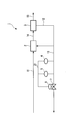
- FIG. 1 is a schematic diagram showing a pure water production apparatus according to one embodiment of the present invention.
- the pure water production apparatus 1 of the present embodiment includes a reverse osmosis raw water tank 2 and a reverse osmosis membrane 3 in this order. Further, the pure water production apparatus 1 of the present embodiment includes a raw water passage 11, a return passage 12, a drain passage 13, a thermometer 4, an electric conductivity meter 5, a flow meter 6, and a control valve 7. Have.
- the reverse osmosis raw water tank 2 is not particularly limited as long as it can store raw water supplied from the raw water channel 11.
- the raw water (water to be treated) supplied to the reverse osmosis raw water tank 2 is preferably water obtained by pre-treatment of tap water, well water, industrial water, or the like, such as turbidity and chlorine removal.
- the reverse osmosis raw water tank 2 is connected to the reverse osmosis membrane 3 via a water channel 14.
- the reverse osmosis membrane 3 separates raw water supplied from the reverse osmosis raw water tank 2 into treated water and concentrated water, and removes ionic substances such as carbonate ions (CO 3 2 ⁇ ) and calcium ions (Ca 2+ ) in the raw water. It is mainly for removal.
- a spiral type module can be suitably used as the reverse osmosis membrane 3.
- the spiral-type module is formed by stacking a plurality of permeable membranes (membrane), winding them in a roll shape, and storing them in a container.
- the reverse osmosis membrane 3 is not limited to a spiral type module.
- the reverse osmosis membrane 3 includes a water channel 15 for sending the treated water out of the system.
- the reverse osmosis membrane 3 is connected to a return path 12 for returning a part of the separated concentrated water to the reverse osmosis raw water tank 2.
- the drain 13 branches from the middle of the return 12.
- the drain 13 is for discharging the remaining portion of the concentrated water discharged from the reverse osmosis membrane 3 (the concentrated water that is not returned to the reverse osmosis raw water tank 2) to the outside of the system.
- the thermometer 4 is provided, for example, in the middle of the drain 13.
- the thermometer 4 is for measuring the temperature of the concentrated water.
- the electric conductivity meter 5 is provided, for example, in the middle of the drain 13.
- the electric conductivity meter 5 is for measuring the electric conductivity of the concentrated water.
- the electric conductivity of the concentrated water measured based on the relationship between the electric conductivity of the raw water and the concentration of silica contained in the raw water, which was investigated in advance, is measured.
- the concentration of silica contained in the concentrated water corresponding to the degree can be derived.
- the flow meter 6 is provided in the middle of the drain 13.
- the flow meter 6 is for measuring the flow rate of the remaining concentrated water flowing through the drain 13.
- the control valve 7 is provided in the middle of the drain 13 and near the flow meter 6.
- the control valve 7 controls the discharge amount of the remaining concentrated water discharged from the drainage channel 13 to the outside of the system based on the measurement values of the thermometer 4, the electric conductivity meter 5, and the flow meter 6.
- the control valve 7 includes a control unit that controls the discharge amount of the remaining portion of the concentrated water based on the measurement values of the thermometer 4, the electric conductivity meter 5, and the flow meter 6.
- the measured value is the temperature of the concentrated water in the thermometer 4.
- the measured value is the electric conductivity of the concentrated water in the electric conductivity meter 5.
- the measured value is the flow rate of the remaining portion of the concentrated water in the flow meter 6.
- the control valve 7 is electrically connected to the thermometer 4, the electric conductivity meter 5, and the flow meter 6 via the signal line 21.
- control valve 7 controls the system based on the relationship between the electric conductivity of the raw water and the concentration of silica contained in the raw water, which has been investigated in advance, so that the silica concentration of the concentrated water does not exceed the silica limit precipitation concentration. Controls the remaining amount of concentrated water discharged to the outside.
- control valve 7 controls the concentration of the concentrated water such that the silica concentration of the concentrated water does not exceed the silica limited precipitation concentration based on an approximate expression indicating a relationship between the temperature of the concentrated water and the silica limit precipitation concentration of the concentrated water at that temperature. Control the discharge of the rest of the water. Thereby, the recovery rate of the treated water can be optimized according to the temperature of the raw water.
- a part of the concentrated water discharged from the reverse osmosis membrane 3 is returned to the reverse osmosis raw water tank 2, and the remaining part of the concentrated water discharged from the reverse osmosis membrane 3 is used as a system.
- the water is discharged to the outside, and based on the measured values of the thermometer 4, the electric conductivity meter 5, and the flow meter 6, the control valve 7 controls the drainage channel 13 so that the silica concentration of the concentrated water does not exceed the silica limit precipitation concentration.
- the control valve 7 controls the drainage channel 13 so that the silica concentration of the concentrated water does not exceed the silica limit precipitation concentration.
- the method for producing pure water of the present embodiment includes a separation step of separating raw water into treated water and concentrated water by a reverse osmosis membrane, and a return step of returning part of the concentrated water obtained in the separation step to the raw water. And a discharge step of discharging the remainder of the concentrated water obtained in the separation step to the outside of the system, a temperature measuring step of measuring the temperature of the concentrated water, and an electric conductivity of measuring the electric conductivity of the concentrated water A measuring step, a flow measuring step of measuring a flow rate of the remaining part of the concentrated water, and a discharge amount of the remaining part of the concentrated water based on the measured values in the temperature measuring step, the electric conductivity measuring step and the flow measuring step. And a control step of controlling
- Raw water is supplied from the raw water channel 11 to the reverse osmosis raw water tank 2.
- the reverse osmosis raw water tank 2 stores raw water.
- raw water is supplied from the reverse osmosis raw water tank 2 to the reverse osmosis membrane 3 via the water channel 14.
- the reverse osmosis membrane 3 separates the raw water into treated water and concentrated water, and removes ionic substances such as carbonate ions and calcium ions in the raw water (separation step).
- the treated water permeating the reverse osmosis membrane 3 contains carbon dioxide (CO 2 ).
- the concentrated water that does not pass through the reverse osmosis membrane 3 contains ionic substances such as carbonate ions and calcium ions.
- the treated water is sent out of the system from the reverse osmosis membrane 3 via the water channel 15.
- the treated water is supplied to a target device (requiring treated water), equipment, or the like.
- thermometer 4 temperature measuring step
- the electric conductivity of the concentrated water is measured by the electric conductivity meter 5 (electric conductivity measuring step).
- the concentration corresponding to the measured electric conductivity of the concentrated water is determined based on the relationship between the electric conductivity of the raw water and the concentration of silica contained in the raw water, which have been investigated in advance.
- the concentration of silica in the water can be derived.
- control valve 7 controls the discharge amount of the remaining concentrated water discharged from the drainage channel 13 to the outside of the system based on the measured values in the temperature measurement step, the electric conductivity measurement step, and the flow rate measurement step (control step). .
- the measured value is the temperature of the concentrated water in the temperature measuring step.
- the measured value is the electric conductivity of the concentrated water in the electric conductivity measuring step.
- the flow rate measuring step it is the flow rate of the remaining portion of the concentrated water.
- the concentration of silica in the concentrated water is determined outside the system so as not to exceed the silica limit precipitation concentration.
- the concentrated water is concentrated so that the silica concentration of the concentrated water does not exceed the silica limited precipitation concentration.
- the concentration of silica in the concentrated water can be derived by measuring the electric conductivity of the concentrated water based on the relationship between the electric conductivity of raw water and the concentration of silica contained in the raw water, which has been investigated in advance.
- the control valve 7 controls the concentration of the concentrated water by the control valve 7 so that the silica concentration of the concentrated water at a specific temperature does not exceed the silica concentration limit of the concentrated water at that temperature. Control the discharge of the rest of the water. Thereby, the recovery rate of the treated water can be optimized according to the temperature of the raw water.
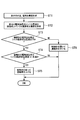
- FIG. 2 is a flowchart relating to control of the silica concentration of the concentrated water.
- the relationship between the electric conductivity of the raw water and the concentration of silica contained in the raw water is measured (ST1).
- the electric conductivity (unit: mS / m) of raw water is measured in accordance with JIS K 0130 “General rules for electric conductivity measurement”.
- JIS K 0130 General rules for electric conductivity measurement”.
- the concentration (unit: ppm) of silica contained in the raw water at each temperature is measured in accordance with, for example, JIS K 0555 “Silica test method in ultrapure water”.
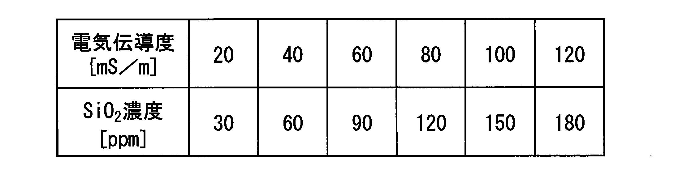
- the electrical conductivity of the raw water and the concentration of silica contained in the raw water were determined. You can know the relationship. ST1 may be performed when the temperature of the raw water changes, and need not always be performed. Table 1 shows the relationship between the electric conductivity of raw water and the concentration of silica contained in raw water. As described above, the electric conductivity of the raw water corresponds to the concentration of silica contained in the raw water.
- the electric conductivity of the concentrated water is equal to or lower than the critical deposition concentration of silica, it is determined whether the electric conductivity of the concentrated water is less than (critical silica concentration-x) (ST4).
- (Silica limit precipitation concentration-x) can be set arbitrarily. When the silica concentration of the concentrated water is significantly lower than the silica limit precipitation concentration, there is room for increasing the silica concentration of the concentrated water. As a standard, (silica limit precipitation concentration-x) is set. x is set in consideration of the operation status of the pure water production apparatus 1.
- the control valve 7 When the electric conductivity of the concentrated water is less than (silica critical deposition concentration-x), the control valve 7 is squeezed to concentrate the silica in the concentrated water (concentration rate of the reverse osmosis membrane unit (the unit including the reverse osmosis membrane 3)). Is raised (ST5). That is, the control valve 7 is squeezed to increase the amount of drainage of the remaining portion of the concentrated water (in other words, to reduce the amount of concentrated water returned to the reverse osmosis raw water tank 2), thereby increasing the concentration rate.
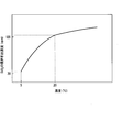
- the critical silica concentration at 20 ° C. is 120 ppm
- the critical silica concentration at 5 ° C. is 30 ppm.
- the silica concentration of the concentrated water is 2a (ppm).
- the silica limit precipitation concentration is 120 ppm. If the silica concentration 2a of the concentrated water is 120 ppm or less, no silica precipitates. In other words, the silica concentration of the concentrated water can be increased (the concentration rate of the reverse osmosis membrane unit can be increased) until 2a becomes 120 ppm.
- the silica limit precipitation concentration at this time is 30 ppm.
- the silica concentration 2a of the concentrated water exceeds 30 ppm, silica is precipitated. In other words, it is necessary to reduce the silica concentration of the concentrated water (reduce the concentration rate of the reverse osmosis membrane unit) until 2a becomes 20 ppm or less.
- a part of the concentrated water obtained in the separation step is returned to the raw water in the reverse osmosis raw water tank 2 in the return step, and is discharged in the separation step in the discharge step.
- the remaining concentration of the obtained concentrated water is discharged out of the system, and the control step causes the silica concentration of the concentrated water to decrease the silica limit precipitation concentration based on the measured values in the temperature measurement step, the electric conductivity measurement step, and the flow rate measurement step.
Landscapes
- Engineering & Computer Science (AREA)
- Water Supply & Treatment (AREA)
- Chemical & Material Sciences (AREA)
- Life Sciences & Earth Sciences (AREA)
- Hydrology & Water Resources (AREA)
- Environmental & Geological Engineering (AREA)
- Organic Chemistry (AREA)
- Nanotechnology (AREA)
- Chemical Kinetics & Catalysis (AREA)
- Separation Using Semi-Permeable Membranes (AREA)
Abstract
本発明の純水製造装置(1)は、原水を収容する逆浸透原水槽(2)と、逆浸透原水槽(2)より供給された原水を処理水と濃縮水に分離する逆浸透膜(3)と、逆浸透膜(3)から排出された濃縮水の一部を逆浸透原水槽(2)に返送する返送路(12)と、濃縮水の残部を系外に排出する排水路(13)と、濃縮水の温度を測定する温度計(4)と、濃縮水の電気伝導度を測定する電気伝導度計(5)と、濃縮水の残部の流量を測定する流量計(6)と、温度計(4)、電気伝導度計(5)および流量計(6)における測定値に基づいて、濃縮水の残部の排出量を制御する制御弁(7)と、を備える。
Description
本発明は、純水製造装置および純水の製造方法に関する。
本願は、2018年6月27日に、日本に出願された特願2018-122115号に基づき優先権を主張し、その内容をここに援用する。
本願は、2018年6月27日に、日本に出願された特願2018-122115号に基づき優先権を主張し、その内容をここに援用する。
半導体製造工場や液晶製造工場等の電子産業分野や研究開発分野にて利用される純水を製造する装置としては、例えば、逆浸透膜が用いられている。
従来、逆浸透膜を用いた純水製造装置としては、例えば、逆浸透膜から給水タンクへ濃縮水を返送させるものが知られている(例えば、特許文献1参照)。
また、逆浸透膜を用いた水処理システムとしては、例えば、逆浸透膜から排出される濃縮水の水質を測定し、シリカのスケールが析出しないように回収率を制御するものが知られている(例えば、特許文献2参照)。
また、逆浸透膜を用いた水処理装置としては、例えば、シリカを含む水の吸光度を測定することにより、シリカ濃度を測定するものが知られている(例えば、特許文献3参照)。
また、逆浸透膜を用いた水処理システムとしては、例えば、逆浸透膜から排出される濃縮水の水質を測定し、シリカのスケールが析出しないように回収率を制御するものが知られている(例えば、特許文献2参照)。
また、逆浸透膜を用いた水処理装置としては、例えば、シリカを含む水の吸光度を測定することにより、シリカ濃度を測定するものが知られている(例えば、特許文献3参照)。
シリカの限界析出濃度(シリカ限界析出濃度)は、水温により変化する。季節変動で水温が変化すると、原水のシリカ限界析出濃度が変動する。原水の温度が低い場合には、回収率(透過水量/原水量)を、原水の温度が高い場合に比べて下げる必要がある。そのため、原水の温度が低い場合に、一定量の透過水量を得ようとすると、原水の温度が高い場合よりも、原水量を増やす必要がある。そうすると、逆浸透膜から排出される濃縮水の量も増える上に、透過水の生産性が低下するという課題があった。
本発明は、上記事情に鑑みてなされたものであって、原水の温度に応じて、処理水の回収率を最適化することができる純水製造装置および純水の製造方法を提供することを目的とする。
[1]原水を収容する逆浸透原水槽と、前記逆浸透原水槽より供給された原水を処理水と濃縮水に分離する逆浸透膜と、前記逆浸透膜から排出された濃縮水の一部を前記逆浸透原水槽に返送する返送路と、前記返送路から分岐して、前記濃縮水の残部を系外に排出する排水路と、前記濃縮水の温度を測定する温度計と、前記濃縮水の電気伝導度を測定する電気伝導度計と、前記濃縮水の残部の流量を測定する流量計と、前記温度計、前記電気伝導度計および前記流量計における測定値に基づいて、前記濃縮水の残部の排出量を制御する制御弁と、を備えたことを特徴とする純水製造装置。
[2]原水を逆浸透膜により処理水と濃縮水に分離する分離工程と、前記分離工程にて得られた濃縮水の一部を前記原水に返送する返送工程と、前記分離工程にて得られた濃縮水の残部を系外に排出する排出工程と、前記濃縮水の温度を測定する温度測定工程と、前記濃縮水の電気伝導度を測定する電気伝導度測定工程と、前記濃縮水の残部の流量を測定する流量測定工程と、前記温度測定工程、前記電気伝導度測定工程および前記流量測定工程における測定値に基づいて、前記濃縮水の残部の排出量を制御する制御工程と、を有することを特徴とする純水の製造方法。
[3]前記制御工程において、予め調査しておいた原水の電気伝導度と原水に含まれるシリカの濃度の関係に基づいて、前記濃縮水のシリカ濃度がシリカ限界析出濃度を超えないように、前記濃縮水の残部の排出量を制御する前記[2]に記載の純水の製造方法。
[4]前記制御工程において、前記濃縮水の温度とその温度における前記濃縮水のシリカ限界析出濃度との関係を示す近似式に基づいて、前記濃縮水のシリカ濃度がシリカ限界析出濃度を超えないように、前記濃縮水の残部の排出量を制御する前記[2]または前記[3]に記載の純水の製造方法。
[2]原水を逆浸透膜により処理水と濃縮水に分離する分離工程と、前記分離工程にて得られた濃縮水の一部を前記原水に返送する返送工程と、前記分離工程にて得られた濃縮水の残部を系外に排出する排出工程と、前記濃縮水の温度を測定する温度測定工程と、前記濃縮水の電気伝導度を測定する電気伝導度測定工程と、前記濃縮水の残部の流量を測定する流量測定工程と、前記温度測定工程、前記電気伝導度測定工程および前記流量測定工程における測定値に基づいて、前記濃縮水の残部の排出量を制御する制御工程と、を有することを特徴とする純水の製造方法。
[3]前記制御工程において、予め調査しておいた原水の電気伝導度と原水に含まれるシリカの濃度の関係に基づいて、前記濃縮水のシリカ濃度がシリカ限界析出濃度を超えないように、前記濃縮水の残部の排出量を制御する前記[2]に記載の純水の製造方法。
[4]前記制御工程において、前記濃縮水の温度とその温度における前記濃縮水のシリカ限界析出濃度との関係を示す近似式に基づいて、前記濃縮水のシリカ濃度がシリカ限界析出濃度を超えないように、前記濃縮水の残部の排出量を制御する前記[2]または前記[3]に記載の純水の製造方法。
本発明によれば、原水の温度に応じて、処理水の回収率を最適化することができる純水製造装置および純水の製造方法を提供できる。
本発明の純水製造装置および純水の製造方法の実施の形態について説明する。
なお、本実施の形態は、発明の趣旨をより良く理解させるために具体的に説明するものであり、特に指定のない限り、本発明を限定するものではない。
なお、本実施の形態は、発明の趣旨をより良く理解させるために具体的に説明するものであり、特に指定のない限り、本発明を限定するものではない。
[純水製造装置]
図1は、本発明の一実施形態に係る純水製造装置を示す模式図である。
図1に示すように、本実施形態の純水製造装置1は、逆浸透原水槽2と、逆浸透膜3とを、この順に備えている。また、本実施形態の純水製造装置1は、原水路11と、返送路12と、排水路13と、温度計4と、電気伝導度計5と、流量計6と、制御弁7とを備えている。
図1は、本発明の一実施形態に係る純水製造装置を示す模式図である。
図1に示すように、本実施形態の純水製造装置1は、逆浸透原水槽2と、逆浸透膜3とを、この順に備えている。また、本実施形態の純水製造装置1は、原水路11と、返送路12と、排水路13と、温度計4と、電気伝導度計5と、流量計6と、制御弁7とを備えている。
逆浸透原水槽2としては、原水路11から供給される原水を収容することができるものであれば、特に限定されない。逆浸透原水槽2に供給される原水(被処理水)は、水道水、井戸水、工業用水等を、予め除濁、除塩素等の前処理を行った水であることが好ましい。
逆浸透原水槽2は、水路14を介して、逆浸透膜3に接続されている。
逆浸透原水槽2は、水路14を介して、逆浸透膜3に接続されている。
逆浸透膜3は、逆浸透原水槽2から供給される原水を処理水と濃縮水に分離し、原水中の炭酸イオン(CO3
2-)やカルシウムイオン(Ca2+)等のイオン性物質を主に除去するためのものである。逆浸透膜3は、スパイラル型モジュールを好適に使用できる。スパイラル型モジュールは、浸透膜(メンブレン)を何層にも重ねてロール状に巻いて容器に収めたものである。逆浸透膜3は、スパイラル型モジュールに限定されるものではない。
逆浸透膜3は、処理水を系外に送るための水路15を備えている。
また、逆浸透膜3は、分離した濃縮水の一部を逆浸透原水槽2に返送する返送路12に接続されている。
逆浸透膜3は、処理水を系外に送るための水路15を備えている。
また、逆浸透膜3は、分離した濃縮水の一部を逆浸透原水槽2に返送する返送路12に接続されている。
排水路13は、返送路12の途中から分岐している。排水路13は、逆浸透膜3から排出された濃縮水の残部(濃縮水のうち逆浸透原水槽2に返送されないもの)を系外に排出するためのものである。
温度計4は、例えば、排水路13の途中に設けられる。温度計4は、濃縮水の温度を測定するためのものである。
電気伝導度計5は、例えば、排水路13の途中に設けられている。電気伝導度計5は、濃縮水の電気伝導度を測定するためのものである。電気伝導度計5により濃縮水の電気伝導度を測定することにより、予め調査しておいた原水の電気伝導度と原水に含まれるシリカの濃度の関係に基づいて、測定した濃縮水の電気伝導度に対応する、濃縮水に含まれるシリカの濃度を導くことができる。
流量計6は、排水路13の途中に設けられている。流量計6は、排水路13を流れる濃縮水の残部の流量を測定するためのものである。
制御弁7は、排水路13の途中でかつ流量計6の近傍に設けられている。制御弁7は、温度計4、電気伝導度計5および流量計6における測定値に基づいて、排水路13から系外に排出する濃縮水の残部の排出量を制御するためのものである。制御弁7は、温度計4、電気伝導度計5および流量計6における測定値に基づいて、濃縮水の残部の排出量を制御する制御部を備えている。
なお、測定値とは、温度計4においては濃縮水の温度である。また、測定値とは、電気伝導度計5においては濃縮水の電気伝導度である。また、測定値とは、流量計6においては濃縮水の残部の流量である。
制御弁7は、信号線21を介して、温度計4、電気伝導度計5および流量計6と電気的に接続されている。
なお、測定値とは、温度計4においては濃縮水の温度である。また、測定値とは、電気伝導度計5においては濃縮水の電気伝導度である。また、測定値とは、流量計6においては濃縮水の残部の流量である。
制御弁7は、信号線21を介して、温度計4、電気伝導度計5および流量計6と電気的に接続されている。
また、制御弁7は、予め調査しておいた原水の電気伝導度と原水に含まれるシリカの濃度の関係に基づいて、濃縮水のシリカ濃度が、シリカ限界析出濃度を超えないように、系外に排出する濃縮水の残部の排出量を制御する。
さらに、制御弁7は、濃縮水の温度とその温度における濃縮水のシリカ限界析出濃度との関係を示す近似式に基づいて、濃縮水のシリカ濃度がシリカ限界析出濃度を超えないように、濃縮水の残部の排出量を制御する。これにより、原水の温度に応じて、処理水の回収率を最適化することができる。
本実施形態の純水製造装置1によれば、逆浸透膜3から排出された濃縮水の一部を逆浸透原水槽2に返送し、逆浸透膜3から排出された濃縮水の残部を系外に排出するとともに、温度計4、電気伝導度計5および流量計6における測定値に基づいて、制御弁7により、濃縮水のシリカ濃度がシリカ限界析出濃度を超えないように、排水路13から系外に排出される濃縮水の残部の排出量を制御する。これにより、濃縮水にシリカが析出して、原水の温度に応じて、処理水の回収率を最適化することができる。そのため、装置の運転管理の負荷を低減することができるとともに、年間の原水使用量と濃縮水の排出量を低減することができる。結果として、装置の運転経費を低減することができる。
[純水の製造方法]
本実施形態の純水の製造方法は、原水を逆浸透膜により処理水と濃縮水に分離する分離工程と、前記分離工程にて得られた濃縮水の一部を前記原水に返送する返送工程と、前記分離工程にて得られた濃縮水の残部を系外に排出する排出工程と、前記濃縮水の温度を測定する温度測定工程と、前記濃縮水の電気伝導度を測定する電気伝導度測定工程と、前記濃縮水の残部の流量を測定する流量測定工程と、前記温度測定工程、前記電気伝導度測定工程および前記流量測定工程における測定値に基づいて、前記濃縮水の残部の排出量を制御する制御工程と、を有する。
本実施形態の純水の製造方法は、原水を逆浸透膜により処理水と濃縮水に分離する分離工程と、前記分離工程にて得られた濃縮水の一部を前記原水に返送する返送工程と、前記分離工程にて得られた濃縮水の残部を系外に排出する排出工程と、前記濃縮水の温度を測定する温度測定工程と、前記濃縮水の電気伝導度を測定する電気伝導度測定工程と、前記濃縮水の残部の流量を測定する流量測定工程と、前記温度測定工程、前記電気伝導度測定工程および前記流量測定工程における測定値に基づいて、前記濃縮水の残部の排出量を制御する制御工程と、を有する。
図1を参照して、本実施形態の純水の製造方法を説明する。
原水路11から逆浸透原水槽2に原水が供給される。
逆浸透原水槽2では、原水が収容される。
原水路11から逆浸透原水槽2に原水が供給される。
逆浸透原水槽2では、原水が収容される。
次いで、原水が、逆浸透原水槽2から水路14を介して逆浸透膜3に供給される。逆浸透膜3は、その原水を処理水と濃縮水に分離し、原水中の炭酸イオンやカルシウムイオン等のイオン性物質を除去する(分離工程)。
原水を逆浸透膜3によって処理すると、逆浸透膜3を透過する処理水には二酸化炭素(CO2)が含まれる。一方、逆浸透膜3を透過しない濃縮水には、炭酸イオンやカルシウムイオン等のイオン性物質が含まれる。
原水を逆浸透膜3によって処理すると、逆浸透膜3を透過する処理水には二酸化炭素(CO2)が含まれる。一方、逆浸透膜3を透過しない濃縮水には、炭酸イオンやカルシウムイオン等のイオン性物質が含まれる。
次いで、逆浸透膜3から水路15を介して、処理水が系外に送られる。処理水は、目的とする(処理水を必要とする)装置、設備等に供給される。
また、逆浸透膜3から返送路12を介して、濃縮水の一部が逆浸透原水槽2に返送される(返送工程)。
また、逆浸透膜3から、返送路12の途中から分岐する排水路13を介して、分離工程にて得られた濃縮水の残部を系外に排出する(排出工程)。
温度計4により、濃縮水の温度を測定する(温度測定工程)。
また、電気伝導度計5により、濃縮水の電気伝導度を測定する(電気伝導度測定工程)。濃縮水の電気伝導度を測定することにより、予め調査しておいた原水の電気伝導度と原水に含まれるシリカの濃度の関係に基づいて、測定した濃縮水の電気伝導度に対応する、濃縮水に含まれるシリカの濃度を導くことができる。
また、流量計6により、排水路13を流れる濃縮水の残部の流量を測定する(流量測定工程)。
さらに、制御弁7により、温度測定工程、電気伝導度測定工程および流量測定工程における測定値に基づいて、排水路13から系外に排出する濃縮水の残部の排出量を制御する(制御工程)。なお、測定値とは、温度測定工程においては濃縮水の温度である。また、測定値とは、電気伝導度測定工程においては濃縮水の電気伝導度である。また、流量測定工程においては濃縮水の残部の流量である。
また、制御工程において、予め調査しておいた原水の電気伝導度と原水に含まれるシリカの濃度の関係に基づいて、濃縮水のシリカ濃度が、シリカ限界析出濃度を超えないように、系外に排出する濃縮水の残部の排出量を制御する。
さらに、制御工程において、濃縮水の温度とその温度における濃縮水のシリカ限界析出濃度との関係を示す近似式に基づいて、濃縮水のシリカ濃度がシリカ限界析出濃度を超えないように、濃縮水の残部の排出量を制御する。濃縮水のシリカの濃度は、予め調査しておいた原水の電気伝導度と原水に含まれるシリカの濃度の関係に基づいて、濃縮水の電気伝導度を測定することによって導くことができる。したがって、濃縮水の電気伝導度の測定値を確認しながら、特定の温度における濃縮水のシリカの濃度が、その温度における濃縮水のシリカ限界析出濃度を超えないように、制御弁7により、濃縮水の残部の排出量を制御する。これにより、原水の温度に応じて、処理水の回収率を最適化することができる。
ここで、図2を参照して、濃縮水のシリカ濃度の制御のフローを説明する。
図2は、濃縮水のシリカ濃度の制御に関するフローチャートである。
図2は、濃縮水のシリカ濃度の制御に関するフローチャートである。
原水の電気伝導度と原水に含まれるシリカの濃度の関係を計測する(ST1)。
ここでは、所定の温度において、例えば、JIS K 0130「電気伝導率測定通則」に準拠して、原水の電気伝導度(単位:mS/m)を測定する。この測定方法によれば、原水に含まれるシリカに起因する電気伝導度を測定することができる。
また、それぞれの温度における原水に含まれるシリカの濃度(単位:ppm)を、例えば、JIS K 0555「超純水中のシリカ試験方法」に準拠して測定する。
上記の測定によって得られた、原水の温度と電気伝導度の関係と、原水の温度とシリカの濃度との関係から、それぞれの温度における、原水の電気伝導度と原水に含まれるシリカの濃度の関係を知ることができる。
なお、ST1は、原水の温度が変化した場合に実施すればよく、常時行う必要はない。
原水の電気伝導度と原水に含まれるシリカの濃度の関係を表1に例示する。このように、原水の電気伝導度と原水に含まれるシリカの濃度は対応している。
ここでは、所定の温度において、例えば、JIS K 0130「電気伝導率測定通則」に準拠して、原水の電気伝導度(単位:mS/m)を測定する。この測定方法によれば、原水に含まれるシリカに起因する電気伝導度を測定することができる。
また、それぞれの温度における原水に含まれるシリカの濃度(単位:ppm)を、例えば、JIS K 0555「超純水中のシリカ試験方法」に準拠して測定する。
上記の測定によって得られた、原水の温度と電気伝導度の関係と、原水の温度とシリカの濃度との関係から、それぞれの温度における、原水の電気伝導度と原水に含まれるシリカの濃度の関係を知ることができる。
なお、ST1は、原水の温度が変化した場合に実施すればよく、常時行う必要はない。
原水の電気伝導度と原水に含まれるシリカの濃度の関係を表1に例示する。このように、原水の電気伝導度と原水に含まれるシリカの濃度は対応している。
原水の電気伝導度と原水に含まれるシリカの濃度の関係式より、シリカ限界析出濃度を推測する(ST2)。
濃縮水の電気伝導度、すなわち、濃縮水のシリカ濃度が、シリカ限界析出濃度以下であるか判断する(ST3)。
濃縮水の電気伝導度が、シリカ限界析出濃度以下である場合、濃縮水の電気伝導度が(シリカ限界析出濃度-x)未満であるか判断する(ST4)。
(シリカ限界析出濃度-x)は、任意に設定することができる。シリカ限界析出濃度よりも濃縮水のシリカ濃度が大幅に低いときには、濃縮水のシリカ濃度を上げる余地がある。その目安として、(シリカ限界析出濃度-x)を設定する。xは純水製造装置1の操業状況を鑑みて設定する。
(シリカ限界析出濃度-x)は、任意に設定することができる。シリカ限界析出濃度よりも濃縮水のシリカ濃度が大幅に低いときには、濃縮水のシリカ濃度を上げる余地がある。その目安として、(シリカ限界析出濃度-x)を設定する。xは純水製造装置1の操業状況を鑑みて設定する。
濃縮水の電気伝導度が(シリカ限界析出濃度-x)未満である場合、制御弁7を絞って、濃縮水のシリカ濃度(逆浸透膜ユニット(逆浸透膜3を含むユニット)の濃縮率)を上げる(ST5)。すなわち、制御弁7を絞って、濃縮水の残部の排水量を増加させる(言い換えれば、逆浸透原水槽2に返送する濃縮水量を減少させる)ことで濃縮率を上げる。
一方、ST4において、濃縮水の電気伝導度が(シリカ限界析出濃度-x)未満でない場合、制御弁7の絞り量をそのままとする。
また、ST3において、濃縮水の電気伝導度が、シリカ限界析出濃度を超える場合、制御弁7を開いて、濃縮水のシリカ濃度(逆浸透膜ユニットの濃縮率)を下げる(ST6)。すなわち、制御弁7を開いて、濃縮水の残部の排水量を減少させる(言い換えれば、逆浸透原水槽2に返送する濃縮水量を増加させる)ことで濃縮率を下げる。
ここで、ST3について詳細に説明する。
図3に示すように、20℃のときのシリカ限界析出濃度は120ppm、5℃のときのシリカ限界析出濃度は30ppmである。
逆浸透膜3に導入する原水のシリカ濃度をa(ppm)とし、逆浸透膜ユニットの濃縮率を50%とすると、濃縮水のシリカ濃度は2a(ppm)となる。
図3に示すように、20℃のときのシリカ限界析出濃度は120ppm、5℃のときのシリカ限界析出濃度は30ppmである。
逆浸透膜3に導入する原水のシリカ濃度をa(ppm)とし、逆浸透膜ユニットの濃縮率を50%とすると、濃縮水のシリカ濃度は2a(ppm)となる。
原水の温度が低温から高温になって、例えば、20℃にあるとき、シリカ限界析出濃度は120ppmである。濃縮水のシリカ濃度2aが120ppm以下であれば、シリカが析出しない。言い換えると、2aが120ppmになるまで、濃縮水のシリカ濃度を上げる(逆浸透膜ユニットの濃縮率を高める)ことができる。
逆に、原水の温度が低下して、高温から低温になって、例えば、5℃になったとき、このときのシリカ限界析出濃度は30ppmである。濃縮水のシリカ濃度2aが30ppmを超えていると、シリカが析出する。言い換えると、2aが20ppm以下になるまで、濃縮水のシリカ濃度を下げる(逆浸透膜ユニットの濃縮率を低くする)必要がある。
本実施形態の純水の製造方法によれば、返送工程により、分離工程にて得られた濃縮水の一部を逆浸透原水槽2内の原水に返送し、排出工程により、分離工程にて得られた濃縮水の残部を系外に排出するとともに、制御工程により、温度測定工程、電気伝導度測定工程および流量測定工程における測定値に基づいて、濃縮水のシリカ濃度がシリカ限界析出濃度を超えないように、排水路13から系外に排出される濃縮水の残部の排出量を制御することにより、濃縮水にシリカが析出して、原水の温度に応じて、処理水の回収率を最適化することができる。そのため、装置の運転管理の負荷を低減することができるとともに、年間の原水使用量と濃縮水の排出量を低減することができる。結果として、装置の運転経費を低減することができる。
1 純水製造装置
2 逆浸透原水槽
3 逆浸透膜
4 温度計
5 電気伝導度計
6 流量計
7 制御弁
11 原水路
12 返送路
13 排水路
14,15 水路
21 信号線
2 逆浸透原水槽
3 逆浸透膜
4 温度計
5 電気伝導度計
6 流量計
7 制御弁
11 原水路
12 返送路
13 排水路
14,15 水路
21 信号線
Claims (4)
- 原水を収容する逆浸透原水槽と、
前記逆浸透原水槽より供給された原水を処理水と濃縮水に分離する逆浸透膜と、
前記逆浸透膜から排出された濃縮水の一部を前記逆浸透原水槽に返送する返送路と、
前記返送路から分岐して、前記濃縮水の残部を系外に排出する排水路と、
前記濃縮水の温度を測定する温度計と、
前記濃縮水の電気伝導度を測定する電気伝導度計と、
前記濃縮水の残部の流量を測定する流量計と、
前記温度計、前記電気伝導度計および前記流量計における測定値に基づいて、前記濃縮水の残部の排出量を制御する制御弁と、を備えたことを特徴とする純水製造装置。 - 原水を逆浸透膜により処理水と濃縮水に分離する分離工程と、
前記分離工程にて得られた濃縮水の一部を前記原水に返送する返送工程と、
前記分離工程にて得られた濃縮水の残部を系外に排出する排出工程と、
前記濃縮水の温度を測定する温度測定工程と、
前記濃縮水の電気伝導度を測定する電気伝導度測定工程と、
前記濃縮水の残部の流量を測定する流量測定工程と、
前記温度測定工程、前記電気伝導度測定工程および前記流量測定工程における測定値に基づいて、前記濃縮水の残部の排出量を制御する制御工程と、を有することを特徴とする純水の製造方法。 - 前記制御工程において、予め調査しておいた原水の電気伝導度と原水に含まれるシリカの濃度の関係に基づいて、前記濃縮水のシリカ濃度がシリカ限界析出濃度を超えないように、前記濃縮水の残部の排出量を制御することを特徴とする請求項2に記載の純水の製造方法。
- 前記制御工程において、前記濃縮水の温度とその温度における前記濃縮水のシリカ限界析出濃度との関係を示す近似式に基づいて、前記濃縮水のシリカ濃度がシリカ限界析出濃度を超えないように、前記濃縮水の残部の排出量を制御することを特徴とする請求項2または3に記載の純水の製造方法。
Applications Claiming Priority (2)
| Application Number | Priority Date | Filing Date | Title |
|---|---|---|---|
| JP2018-122115 | 2018-06-27 | ||
| JP2018122115A JP2020000984A (ja) | 2018-06-27 | 2018-06-27 | 純水製造装置、純水の製造方法 |
Publications (1)
| Publication Number | Publication Date |
|---|---|
| WO2020004542A1 true WO2020004542A1 (ja) | 2020-01-02 |
Family
ID=68986640
Family Applications (1)
| Application Number | Title | Priority Date | Filing Date |
|---|---|---|---|
| PCT/JP2019/025573 Ceased WO2020004542A1 (ja) | 2018-06-27 | 2019-06-27 | 純水製造装置、純水の製造方法 |
Country Status (3)
| Country | Link |
|---|---|
| JP (1) | JP2020000984A (ja) |
| TW (1) | TW202000296A (ja) |
| WO (1) | WO2020004542A1 (ja) |
Families Citing this family (1)
| Publication number | Priority date | Publication date | Assignee | Title |
|---|---|---|---|---|
| JP7630250B2 (ja) * | 2020-09-29 | 2025-02-17 | 三菱重工業株式会社 | プラントの水質管理装置及びプラント並びにプラントの水質管理方法 |
Citations (2)
| Publication number | Priority date | Publication date | Assignee | Title |
|---|---|---|---|---|
| JP2012206073A (ja) * | 2011-03-30 | 2012-10-25 | Kurita Water Ind Ltd | 脱イオン水製造システム |
| JP2013146684A (ja) * | 2012-01-19 | 2013-08-01 | Miura Co Ltd | 逆浸透膜分離装置 |
-
2018
- 2018-06-27 JP JP2018122115A patent/JP2020000984A/ja active Pending
-
2019
- 2019-06-27 TW TW108122645A patent/TW202000296A/zh unknown
- 2019-06-27 WO PCT/JP2019/025573 patent/WO2020004542A1/ja not_active Ceased
Patent Citations (2)
| Publication number | Priority date | Publication date | Assignee | Title |
|---|---|---|---|---|
| JP2012206073A (ja) * | 2011-03-30 | 2012-10-25 | Kurita Water Ind Ltd | 脱イオン水製造システム |
| JP2013146684A (ja) * | 2012-01-19 | 2013-08-01 | Miura Co Ltd | 逆浸透膜分離装置 |
Also Published As
| Publication number | Publication date |
|---|---|
| JP2020000984A (ja) | 2020-01-09 |
| TW202000296A (zh) | 2020-01-01 |
Similar Documents
| Publication | Publication Date | Title |
|---|---|---|
| JP4973853B2 (ja) | 純水製造システム | |
| JP5222526B2 (ja) | 水処理方法ならびに水処理装置 | |
| JP2008307487A (ja) | 脱塩装置 | |
| CN114206785A (zh) | 水处理系统以及水处理方法 | |
| TWI723224B (zh) | 逆滲透膜裝置的運轉管理方法以及逆滲透膜處理系統 | |
| JP2012192373A (ja) | 水処理装置 | |
| WO2020004542A1 (ja) | 純水製造装置、純水の製造方法 | |
| CN109437445B (zh) | 高盐废水资源化再利用的方法 | |
| EP3959177A1 (en) | Coated substrate and process of preparation | |
| KR20230167342A (ko) | 전기탈이온 시스템 및 전기탈이온 시스템의 제어 방법 | |
| JP2009285522A (ja) | 逆浸透膜装置 | |
| JP7269136B2 (ja) | 純水製造装置 | |
| WO2018138957A1 (ja) | 電気伝導度によるpH制御方法 | |
| JP4432583B2 (ja) | 超純水製造装置 | |
| WO2020166276A1 (ja) | 逆浸透システムの制御方法 | |
| JP2005246281A (ja) | 海水淡水化方法および海水淡水化装置 | |
| JP7147291B2 (ja) | 純水製造装置、純水の製造方法 | |
| JP7405066B2 (ja) | 超純水製造装置及び超純水製造方法 | |
| JP2017209624A (ja) | 水処理システム | |
| JP2005081254A (ja) | 逆浸透膜装置 | |
| JP2017064570A (ja) | 膜処理装置、飲料用水製造装置、膜処理方法、及び飲料用水製造方法 | |
| CN111545066A (zh) | 净水过滤装置 | |
| TW202200506A (zh) | 純水製造方法 | |
| JP7492876B2 (ja) | 水処理方法および水処理装置 | |
| TW202440475A (zh) | 水處理方法及水處理裝置 |
Legal Events
| Date | Code | Title | Description |
|---|---|---|---|
| 121 | Ep: the epo has been informed by wipo that ep was designated in this application |
Ref document number: 19826283 Country of ref document: EP Kind code of ref document: A1 |
|
| NENP | Non-entry into the national phase |
Ref country code: DE |
|
| 122 | Ep: pct application non-entry in european phase |
Ref document number: 19826283 Country of ref document: EP Kind code of ref document: A1 |