WO2020004477A1 - 保冷具包材、梱包容器及び保冷対象物の輸送方法 - Google Patents
保冷具包材、梱包容器及び保冷対象物の輸送方法 Download PDFInfo
- Publication number
- WO2020004477A1 WO2020004477A1 PCT/JP2019/025412 JP2019025412W WO2020004477A1 WO 2020004477 A1 WO2020004477 A1 WO 2020004477A1 JP 2019025412 W JP2019025412 W JP 2019025412W WO 2020004477 A1 WO2020004477 A1 WO 2020004477A1
- Authority
- WO
- WIPO (PCT)
- Prior art keywords
- radiant heat
- heat
- cooled
- packaging material
- packaging
- Prior art date
- Legal status (The legal status is an assumption and is not a legal conclusion. Google has not performed a legal analysis and makes no representation as to the accuracy of the status listed.)
- Ceased
Links
Images




Classifications
-
- B—PERFORMING OPERATIONS; TRANSPORTING
- B65—CONVEYING; PACKING; STORING; HANDLING THIN OR FILAMENTARY MATERIAL
- B65D—CONTAINERS FOR STORAGE OR TRANSPORT OF ARTICLES OR MATERIALS, e.g. BAGS, BARRELS, BOTTLES, BOXES, CANS, CARTONS, CRATES, DRUMS, JARS, TANKS, HOPPERS, FORWARDING CONTAINERS; ACCESSORIES, CLOSURES, OR FITTINGS THEREFOR; PACKAGING ELEMENTS; PACKAGES
- B65D81/00—Containers, packaging elements, or packages, for contents presenting particular transport or storage problems, or adapted to be used for non-packaging purposes after removal of contents
- B65D81/18—Containers, packaging elements, or packages, for contents presenting particular transport or storage problems, or adapted to be used for non-packaging purposes after removal of contents providing specific environment for contents, e.g. temperature above or below ambient
-
- F—MECHANICAL ENGINEERING; LIGHTING; HEATING; WEAPONS; BLASTING
- F25—REFRIGERATION OR COOLING; COMBINED HEATING AND REFRIGERATION SYSTEMS; HEAT PUMP SYSTEMS; MANUFACTURE OR STORAGE OF ICE; LIQUEFACTION SOLIDIFICATION OF GASES
- F25D—REFRIGERATORS; COLD ROOMS; ICE-BOXES; COOLING OR FREEZING APPARATUS NOT OTHERWISE PROVIDED FOR
- F25D3/00—Devices using other cold materials; Devices using cold-storage bodies
Definitions
- the present invention relates to a method for transporting a cool packaging material, a packaging container, and an object to be kept cool.
- Priority is claimed on Japanese Patent Application No. 2018-125108 filed on June 29, 2018, the content of which is incorporated herein by reference.
- Patent Document 1 discloses that various articles such as medicines, medical devices, specimens, organs, chemical substances, and foods requiring temperature control are kept at a predetermined temperature by keeping them cool through a space using a heat storage material.
- a transportable container is disclosed.
- This container is a constant-temperature storage / transport container made of a foaming container having a relatively simple structure and excellent heat insulation performance, without causing a decrease in heat insulation performance due to damage such as damage during handling.
- a specific amount of a hydrocarbon-based foaming agent and a radiant heat transfer inhibitor are used as the insulated container.
- a molded article composed of expandable styrene-based resin particles is used.
- One embodiment of the present invention has been made in view of the above-described problems of the related art, and manages the temperature of an object to be transported at a temperature that is the melting point of a heat storage material, and can set the temperature without being affected by an outside air temperature or the like. It is an object of the present invention to provide a method for transporting a cool pack packaging material, a packaging container, and an object to be kept cool.
- the cooler packaging material of one embodiment of the present invention has a first radiant heat reflective layer that reflects radiant heat, a second radiant heat reflective layer that reflects radiant heat, and a latent heat storage material, It has a plurality of heat exchange portions that are in proximity to or in contact with the cold insulation object, and a connection portion that connects two heat exchange portions adjacent to each other, and the first radiation heat reflection layer and the second radiation heat reflection layer are respectively
- the heat exchange part and the connection part are formed on a surface facing the object to be kept cool and on a surface opposite to the object to be kept cool.
- the temperature of an object to be transported is controlled by the temperature that is the melting point of the heat storage material, and the heat insulator packaging material, the packaging container, and the object to be cooled that can be set without being affected by the outside air temperature or the like.
- Transportation method can be provided.
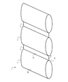
- FIG. 1 is a schematic diagram illustrating a configuration of a cool pack packaging material according to one embodiment of the present invention.
- FIG. 2A is a perspective view showing the cool packaging material according to the first embodiment.
- FIG. 2B is a conceptual diagram relating to a contact portion between the cool insulating device packaging material and the cold insulating object.
- FIG. 3 is a sectional view taken along the line III-III 'shown in FIG. 2A.
- FIG. 4 is an enlarged view of a region IV shown in FIG.
- FIG. 5 is a perspective view showing a cool pack packaging material according to the second embodiment.
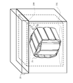
- FIG. 6 is a perspective view showing a packing container for storing the cooler packaging material according to the second embodiment (Example 1).
- FIG. 1 is a schematic diagram illustrating a configuration of a cool pack packaging material according to one embodiment of the present invention.
- FIG. 2A is a perspective view showing the cool packaging material according to the first embodiment.
- FIG. 2B is a conceptual diagram
- FIG. 7 is a schematic diagram showing a cool pack packaging material according to the third embodiment.
- FIG. 8 is a perspective view showing a packaging container for storing a cool pack packaging material according to the third embodiment (Example 2).
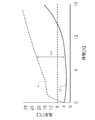
- FIG. 9 is a temperature characteristic diagram illustrating a temperature change of the cold-holding object 4 in the case of the second embodiment.
- FIG. 10 is a temperature characteristic diagram showing a temperature change of the cold storage object 4 in the case of Comparative Example 2.
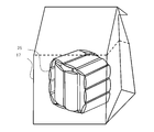
- FIG. 11 is a perspective view showing a cool pack packaging material according to the fourth embodiment.
- FIG. 12 is a perspective view showing a packing container for storing a cool pack packaging material according to the fourth embodiment (Example 3).
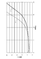
- FIG. 13 is a temperature characteristic diagram showing a temperature change of the cold storage object 4 in the case of the third embodiment.
- the configuration of the cool pack 1 according to one embodiment of the present invention is filled with a latent heat storage material having a main melting point of 3 ° C. (for example, an aqueous solution containing potassium bromide in tetrabutylammonium bromide).
- a plurality of heat exchange units 2 are connected by a connection unit 3.
- the heat exchange unit 2 is formed from a packaging material made of a nylon film on which aluminum is deposited by a packaging machine. Since aluminum reflects heat, the radiant heat reflecting layers 2A and 2B that reflect radiant heat are formed by the aluminum.
- connection part 3 is formed of a packaging material made of a nylon film on which aluminum is deposited by a packaging machine, similarly to the heat exchange part 2. Similar to the heat exchange part 2, the connection part 3 has radiant heat reflection layers 3A and 3B that reflect radiant heat by aluminum that reflects heat. In addition, the connection portions 3 can adjust the angles of the heat exchange portions 2 adjacent to each other.
- the cool pack 10 covers the top and bottom surfaces of the cold pack 4 to be kept cool, and the cold pack 16 covers the side of the cool pack 4. Covering. Since the connecting portions 3 can adjust the angles of the heat exchanging portions 2 adjacent to each other, the cool keeping device packaging materials 10 and 16 can cover the cold keeping target 4.
- the structure of the cold insulation packaging materials 10 and 16 is the same as the structure of the cold insulation packaging material 1.
- a material that absorbs moisture such as a nonwoven fabric, may be wound around the object to be cooled to form the object 4 to be cooled.
- the heat insulator packaging materials 10 and 16 are all close to or in contact with each other on the surface facing the cold insulator 4 (hereinafter, may be referred to as the entire circumference), and more than half of the heat exchange It is assumed that the part 2 is in contact with the object 4 to be kept cool.
- the heat exchange unit 2 When the heat exchange unit 2 is in contact with the object 4, as shown in the conceptual diagram of FIG. 2B, the surface of the heat exchange unit 2 where the heat exchange unit 2 and the object 4 are in contact with each other. It is preferable that the heat exchange unit 2 and the cold-holding object 4 are in contact with each other with a contact area 2C that is equal to or more than half of the surface area.
- the radiant heat reflecting layers 2A and 3A are formed on the surface facing the cold insulation target 4, and reflect the radiant heat 7 (FIG. 4) described later from the inside of the area covered by the cool insulation packaging materials 10 and 16.
- the radiant heat reflecting layers 2B and 3B reflect radiant heat 5 (FIG. 3) described later from outside the area covered by the cooler packaging materials 10 and 16.
- FIG. 3 which is a cross-sectional view taken along the line III-III ′ of FIG. 2A, in a portion where the heat exchanging unit 2 provided in the cool keeping device packagings 10 and 16 is in contact with the cool keeping object 4, The object 4 is directly cooled.
- FIG. 4 which is an enlarged view of the region IV in FIG. 3, the radiant heat 7 is also emitted in the space between the cold insulation object 4 and the cold insulation packaging materials 10 and 16.
- the heat insulator packaging materials 10 and 16 according to the present embodiment by being in direct contact with the object 4 to be kept cool, have an effect that the heat conduction 6 causes the melting temperature of the latent heat storage material included in the heat exchange section 2 to be close to the melting point of the latent heat storage material. It is possible to keep the object 4 cool longer than in the case where the object 4 is kept cool through a space without directly contacting the packaging materials 10 and 16.
- the cooler packaging materials 10 and 16 are provided with the radiant heat reflecting layers 2A and 3A that reflect the radiant heat 7, thereby reflecting the radiant heat 7 from the inside of the area covered by the cooler packaging materials 10 and 16. Then, the object 4 is kept cool.
- the cold insulator packaging materials 10 and 16 are provided with the radiant heat reflecting layers 2B and 3B that reflect the radiant heat 5, the chilled heat reflecting materials 2 and 3B reflect the radiant heat 5 from the outside of the area covered by the cold insulator packaging materials 10 and 16 to cool the object. Keep 4 cool.
- FIG. 5 shows the cool insulator packaging material 16 according to the present embodiment.
- the upper part and the lower part are covered with the cold insulator packaging material 10
- the cold insulator packaging material 16 is sealed by the bag-shaped packaging material 17 sealed at the upper part.
- the whole is covered.
- the bag-like packaging material 17 for example, a material in which foamed polyethylene is coated with aluminum is used.
- the bag-like packaging material 17 is arranged so that aluminum, which is the radiant heat reflection layer 17A, faces a surface facing the cooler packaging material 16.
- the radiant heat reflecting layer 17A makes it possible to reflect the radiant heat 8 from the upper and lower portions of the object 4 not covered by the cooler packaging 16, and when the upper and lower portions cannot be covered by the cooler packaging 16. It is also possible to effectively keep the object 4 to be kept cool. Further, in the present embodiment, since the bag 16 is wrapped with the bag 16, the object 4 to be cooled can be carried integrally with the bag 16, thereby improving portability.
- Example 1 The following verification was performed in order to evaluate the temperature change of the cold storage object 4 in the present embodiment.
- the packaging material 16 was frozen in a freezer at ⁇ 18 ° C., and then allowed to stand in a thermostat at 2 ° C. until the temperature of the packaging material 16 became 2 ° C.
- the bag-like packaging material 17 was accommodated in an environment of 4 ° C. in a packing container 29 having a cargo room volume of 20 L.
- the packing container 29 is used for the purpose of insulating the inside and the outside of the packing container 29, and does not have to have the purpose of keeping the space in the packing container 29 cool (hereinafter, may be referred to as space cooling).
- space cooling a packing container radiant heat reflection layer 29A that reflects the radiant heat 9 with aluminum or the like is formed.
- the packaging container 29 is allowed to stand still in a constant temperature bath in which the environmental temperature is set to 40 ° C., and the temperature of the object 4 to be cooled and the temperature of the air in the packaging container 29 are measured by a temperature measuring device with a data logger.
- the temperature change of the cold storage object 4 was evaluated. Specifically, as the cooling efficiency, a value obtained by dividing the time during which the cooling object 4 is kept at a temperature equal to or lower than the set value (8 ° C. in one embodiment of the present invention) by the weight of the cooling material packaging 16 is obtained. Was. In this embodiment, the cooling efficiency was 6.8 h / kg.
- FIG. 7 shows a cool pack packaging material 25 according to the present embodiment.
- the cool pack packaging 25 is composed of the cool pack 16 and the cool packs 27 and 28 having the same configuration as the cool pack 1.
- the bag 18 is used to cover the entirety of the cooler packaging 16, but in the present embodiment, the cooler packagings 27 and 28 are used to cool the cooler. The entire packaging material 16 is covered.
- the side surface of the object 4 is double-covered by wrapping the wrapping material 27 around the outer surface of the wrapping material 16, and the wrapping material 28 is wrapped around the top and bottom surfaces of the object 4. (Hereinafter, it may be referred to as the entire circumference partly double).
- the cold insulator packaging material 16 and the cold insulator packaging material 27 may be connected by the connection portion 3.
- the upper surface and the lower surface of the cooling object 4 are doubly covered by the radiant heat reflecting layers 2A, 3A and the radiant heat reflecting layers 2B, 3B of the cooling device packaging material 28.
- the side surfaces of the object 4 for keeping cool are the radiant heat reflecting layers 2A, 3A and the radiant heat reflecting layers 2B, 3B of the wrapping material for the cool keeping device 16, the radiant heat reflecting layers 2A, 3A and the radiant heat reflecting layers 2B, 3B of the wrapping material for the cool keeping device 27, Covered four times.
- the cold storage wrapping material 25 has more radiant heat reflecting layers 2A and 3A as compared with the first and second embodiments, so that the cold storage efficiency is improved.
- Example 2 As shown in FIG. 8, the verification was performed under the same conditions as in Example 1 except that the packaging materials 27 and 28 were used instead of the bag-like packaging material 17.
- the weight of the cool pack 16 was 0.6 kg
- the total weight of the cool packs 27 and 28 was 1.4 kg
- the total weight of the cool pack 25 was 2 kg.
- the packaging container 29 was allowed to stand still in a constant-temperature bath in which the environmental temperature was set to 40 ° C., and the temperature of the object 4 to be cooled and the temperature of the air in the packaging container 29 were measured for 18 hours using a temperature measuring device with a data logger. As shown in FIG.
- the graph 31 in FIG. 9 shows the change over time in the temperature of the air in the packing container 29, and the graph 32 shows the change over time in the temperature of the object 4 to be cooled.
- the temperature in the packaging container 29 rapidly rose to 15 ° C. in about 2 hours after the start of the measurement, and then gradually rose. This increase in temperature is considered to be due to heat flowing into the packing container 29 from the outside.
- the object 4 to be kept cool is kept at 2 ° C. to 8 ° C. for 14.3 hours from the start of the measurement.
- the cooling efficiency is calculated by dividing 14.3 hours of the cooling time by the weight of the cooling material packaging material 2 of 2 kg, and is 7.2 h / kg. Since 2 ° C to 8 ° C is within the control temperature range of pharmaceuticals, it was set as a value to be considered in this verification.
- Example 1 Verification was performed under the same conditions as in Example 2 except that the cooler packaging material 25 on which aluminum was not deposited was used.
- the cooling efficiency was 5.7 h / kg, which was lower than that of Example 2. This is because the cold storage device packaging material 25 in the present comparative example does not reflect the radiant heat 11, and thus the latent heat storage material included in the cold storage device packaging material 25 in the present comparative example is melted earlier than in the second embodiment. Conceivable.
- Comparative Example 2 This comparative example was verified in order to verify that one embodiment of the present invention does not perform space cooling but only the cooling object 4 to keep the cooling efficiency high.
- a rigid container made of polyethylene was filled with 1 kg of the same latent heat storage material as in Example 2 instead of the cooler packaging material 25 (hereinafter, may be referred to as a cooler of this comparative example).
- a total of four were prepared.
- Other conditions were the same as in Example 2.
- 2Two cold insulators of this comparative example were installed on the upper portion 29B and the lower portion 29C of the packing container 29 shown in FIG.
- the object 4 to be kept cool is placed on the cooler of the present comparative example.
- the cooler of this comparative example is fixed to, for example, the lid of the packing container 29.
- FIG. 10 shows the verification results of this comparative example.
- a graph 33 shows a change with time of the temperature of the air in the packing container 29, and a graph 34 shows a change with time of the temperature of the object 4 to be cooled.
- the temperature of the cold storage object 4 did not become constant at 3 ° C., which is the melting point of the latent heat storage material, but gradually increased within 6 hours (0h to 6h) from the start of verification. During the further 6 hours (6h to 12h), the temperature of the cold storage object 4 was about 7 ° C., which is higher than 3 ° C., which is the melting point of the latent heat storage material. On the other hand, in Example 2, the cooling object 4 was kept at 3 ° C., which is the melting point of the latent heat storage material, for a long time (see FIG. 9, 2h to 10h).
- the object 4 to be cooled is covered with the packaging material 25, and the radiant heat reflecting layers 2A, 2B, 3A, 3B prevent heat inflow (radiant heat 11) by reflection. Therefore, the temperature inside the packing container 29 increases, but the temperature of the object 4 to be cooled is kept near the melting point of the latent heat storage material.
- heat conduction 6 is also performed because the cold insulator packaging material 25 is in direct contact with the cold insulator 4. For this reason, the temperature difference 32A between the inside of the packing container 29 and the object 4 to be kept cool increases.
- the temperature difference 34A between the temperature inside the packing container 29 and the object 4 to be cooled is small. This is because the cold heat of the cooler of the present comparative example moderates the heat inflow from the outside of the packaging container 29, and then keeps the cold storage object 4 cool.
- the cooling efficiency of this comparative example was 4.0 h / kg.
- FIG. 11 shows a cooler packaging material 25 covered with a bag-like packaging material 17 according to the present embodiment.
- This embodiment is the same as the third embodiment except that it is covered with the bag-like packaging material 17.
- the object 4 to be refrigerated can be carried integrally with the refrigeration packaging material 25, and portability is improved.
- the refrigerating tool packaging material 25 having a high refrigerating efficiency is used, the refrigerating efficiency is also increased.
- Example 3 As shown in FIG. 12, the verification was performed under the same conditions as in Example 2 except that the bag-shaped packaging material 17 was used, and the measurement result of the temperature of the cold storage object 4 shown in FIG. 13 was obtained.
- the cold keeping time for keeping the cold keeping object 4 cooler was longer than that of the second embodiment.
- the cooling efficiency in the present example was 8.8 h / kg.
- Example 2 even if the packaging material covering the cooler packaging material 16 is the cooler packaging material 27 or 28 containing the latent heat storage material, it does not contain the latent heat storage material. Even in the case of the bag-like packaging material 17, the cooling efficiency does not change so much as about 0.5h / kg.
- the cooling efficiency is only about 0.5 h / kg, if the radiant heat reflecting layer 2A, 2B, 3A, 3B, 17A is formed on the packaging material covering the cooling packaging material 16, the cooling packaging material 16 will not be used. It turns out that it is not important whether the covering material contains the latent heat storage material.
- the present invention is not limited to the above embodiment, and various modifications are possible.
- a structure substantially the same as the structure described in the above embodiment, a structure exhibiting the same function and effect, or a structure capable of achieving the same object can be used.
- the radiant heat reflecting layer may be formed of other materials such as silver as long as the radiant heat is reflected.
- the first radiant heat reflection layer and the second radiant heat reflection layer in the claims correspond to, for example, the radiant heat reflection layers 2A, 3A and 2B, 3B, and the third radiant heat reflection layer is the radiant heat reflection layer 17A. Is equivalent to
Landscapes
- Engineering & Computer Science (AREA)
- Mechanical Engineering (AREA)
- Chemical & Material Sciences (AREA)
- Combustion & Propulsion (AREA)
- Physics & Mathematics (AREA)
- Thermal Sciences (AREA)
- General Engineering & Computer Science (AREA)
- Packages (AREA)
Abstract
輸送対象物の温度を蓄熱材の融点となる温度で管理し、外気温などの影響を受けずに設定できる保冷具包材、梱包容器及び保冷対象物の輸送方法を提供する。保冷具包材は、輻射熱を反射する第1の輻射熱反射層と、輻射熱を反射する第2の輻射熱反射層と、潜熱蓄熱材が封入され、保冷対象物と近接又は接触する複数の熱交換部と、互いに隣接した2つの熱交換部を接続する接続部と、を有し、第1の輻射熱反射層及び第2の輻射熱反射層は、それぞれ熱交換部及び接続部の保冷対象物に相対する面及び保冷対象物とは反対側の面に形成されている。
Description
本発明は、保冷具包材、梱包容器及び保冷対象物の輸送方法に関する。
本願は、2018年6月29日に、日本に出願された特願2018-125108に優先権を主張し、その内容をここに援用する。
本願は、2018年6月29日に、日本に出願された特願2018-125108に優先権を主張し、その内容をここに援用する。
特許文献1には、温度管理の必要な医薬品や医療機器、検体、臓器、化学物質、食品などの各種物品を、蓄熱材を用いて空間を介して保冷することで、所定の温度に維持して輸送できる容器が開示されている。この容器は、取扱い時の傷つきなどの破損による断熱性能低下が発生せず、比較的構造が簡易な断熱性能の優れた発泡容器からなる定温保管輸送容器である。特許文献1に記載の発明においては、所望の温度に対応する蓄熱材を断熱容器内に配置する定温保管輸送容器において、断熱容器として、特定量の炭化水素系発泡剤および輻射伝熱抑制剤を含む発泡性スチレン系樹脂粒子からなる成形品を用いる。
しかしながら、外気温に左右されず低温管理を実現するためには、特許文献1に記載された構成では、輻射伝熱抑制機能や熱伝導率を正確に把握した断熱容器を設計する必要があった。このため、融解特性を利用する蓄熱材と凝固特性を利用する蓄熱材などを用いる必要があり、複数の蓄熱材を用いる熱物性を設計及び設定しなければならなかった。
本発明の一つの態様は、上記従来技術の問題に鑑みなされたものであって、輸送対象物の温度を蓄熱材の融点となる温度で管理し、外気温などの影響を受けずに設定できる保冷具包材、梱包容器及び保冷対象物の輸送方法を提供することを目的とする。
上記課題を解決するため、本発明の一態様の保冷具包材は、輻射熱を反射する第1の輻射熱反射層と、輻射熱を反射する第2の輻射熱反射層と、潜熱蓄熱材が封入され、保冷対象物と近接又は接触する複数の熱交換部と、互いに隣接した2つの熱交換部を接続する接続部と、を有し、第1の輻射熱反射層及び第2の輻射熱反射層は、それぞれ熱交換部及び接続部の保冷対象物に相対する面及び保冷対象物とは反対側の面に形成されている。
本発明の一態様によれば、例えば、輸送対象物の温度を蓄熱材の融点となる温度で管理し、外気温などの影響を受けずに設定できる保冷具包材、梱包容器及び保冷対象物の輸送方法を提供することができる。
以下、本発明の実施の形態について、図面を参照しながら説明する。
図1に示すように本発明の一態様の保冷具包材1の構成は、3℃に主な融点を有する潜熱蓄熱材(たとえばテトラブチルアンモニウムブロミドに臭化カリウムを含む水溶液)が充填された熱交換部2が接続部3によって複数接続されている。
熱交換部2は、包装機によってアルミニウムが蒸着されたナイロンフィルムからなる包材から形成される。アルミニウムは熱を反射するため、このアルミニウムによって輻射熱を反射する輻射熱反射層2A,2Bが形成されている。
接続部3は、熱交換部2と同様に、包装機によってアルミニウムが蒸着されたナイロンフィルムからなる包材から形成される。接続部3は、熱交換部2と同様に、熱を反射するアルミニウムによって輻射熱を反射する輻射熱反射層3A,3Bが形成されている。また接続部3は互いに隣接する熱交換部2の角度の調整が可能である。
[第1の実施の形態]
図2Aに示すように本実施の形態においては、保冷具包材10は、保冷する対象である保冷対象物4の上面及び底面を覆い、保冷具包材16は、保冷対象物4の側面を覆っている。接続部3が互いに隣接する熱交換部2の角度を調整可能なため、保冷具包材10,16は保冷対象物4を覆うことが可能となる。なお保冷具包材10,16の構成は保冷具包材1の構成と同等とする。また結露の対策として、保冷する対象に不織布などの水分を吸収する素材を巻き付けて保冷対象物4としてもよい。
図2Aに示すように本実施の形態においては、保冷具包材10は、保冷する対象である保冷対象物4の上面及び底面を覆い、保冷具包材16は、保冷対象物4の側面を覆っている。接続部3が互いに隣接する熱交換部2の角度を調整可能なため、保冷具包材10,16は保冷対象物4を覆うことが可能となる。なお保冷具包材10,16の構成は保冷具包材1の構成と同等とする。また結露の対策として、保冷する対象に不織布などの水分を吸収する素材を巻き付けて保冷対象物4としてもよい。
本発明の一態様においては、保冷具包材10,16が保冷対象物4と相対する面において、すべて近接又は接触しており(以下、全周包囲と呼んでもよい)、半数以上の熱交換部2が保冷対象物4と接触しているものとする。
なお熱交換部2と保冷対象物4とが接触している場合は、図2Bの概念図に示すように、熱交換部2と保冷対象物4とが接触している熱交換部2の面の表面積の半分以上の接触面積2Cで、熱交換部2と保冷対象物4とが接触していることが好ましい。
輻射熱反射層2A,3Aは、保冷対象物4に相対する面に形成され、保冷具包材10,16によって覆われた領域の内側からの後述の輻射熱7(図4)を反射する。輻射熱反射層2B,3Bは、保冷具包材10,16によって覆われた領域の外側からの後述の輻射熱5(図3)を反射する。
図2AのIII-III’断面図である図3に示すように、保冷具包材10,16が備える熱交換部2が保冷対象物4に接触している部分において、熱伝導6によって保冷対象物4を直接保冷する。
図3における領域IVの拡大図である図4に示すように、保冷対象物4と保冷具包材10,16との間の空間においても輻射熱7は放出される。
本実施の形態における保冷具包材10,16は、保冷対象物4に直接接触することで熱伝導6によって熱交換部2に含まれる潜熱蓄熱材の融解温度を潜熱蓄熱材の融点付近で効果的に保つことが可能となり、保冷対象物4が保冷具包材10,16に直接接触せずに空間を介して保冷する場合と比べ保冷対象物4を長く保冷できる。
これに加えて、保冷具包材10,16は、輻射熱7を反射する輻射熱反射層2A,3Aを備えることで、保冷具包材10,16によって覆われた領域の内側からの輻射熱7を反射し保冷対象物4を保冷する。また保冷具包材10,16は、輻射熱5を反射する輻射熱反射層2B,3Bを備えることで、保冷具包材10,16によって覆われた領域の外側からの輻射熱5を反射し保冷対象物4を保冷する。
[第2の実施の形態]
図5に本実施の形態による保冷具包材16を示す。第1の実施の形態では、上部及び下部を保冷具包材10が覆っていたのに対して、本実施の形態においては上部に封がされた袋状包材17によって保冷具包材16の全体が覆われている。袋状包材17は、例えば発泡ポリエチレンにアルミニウムがコーティングされた材料が使用される。袋状包材17は、保冷具包材16と対面する面に輻射熱反射層17Aであるアルミニウムが向くように配置する。
図5に本実施の形態による保冷具包材16を示す。第1の実施の形態では、上部及び下部を保冷具包材10が覆っていたのに対して、本実施の形態においては上部に封がされた袋状包材17によって保冷具包材16の全体が覆われている。袋状包材17は、例えば発泡ポリエチレンにアルミニウムがコーティングされた材料が使用される。袋状包材17は、保冷具包材16と対面する面に輻射熱反射層17Aであるアルミニウムが向くように配置する。
輻射熱反射層17Aにより、保冷具包材16によって覆われていない保冷対象物4の上部及び下部からの輻射熱8を反射することが可能となり、保冷具包材16によって上部及び下部を覆えない場合においても効果的に保冷対象物4を保冷することが可能となる。また本実施の形態においては、袋状包材17によって保冷具包材16を包むため、保冷対象物4を保冷具包材16と一体として持ち運ぶことが可能となり可搬性がよくなる。
(実施例1)
本実施の形態における保冷対象物4の温度変化を評価するために以下の検証を行った。まず、保冷具包材16を、-18℃の冷凍庫内で凍結させた後、2℃の恒温槽内に保冷具包材16の温度が2℃となるまで静置した。
本実施の形態における保冷対象物4の温度変化を評価するために以下の検証を行った。まず、保冷具包材16を、-18℃の冷凍庫内で凍結させた後、2℃の恒温槽内に保冷具包材16の温度が2℃となるまで静置した。
次に、4℃で保冷された血液を模した水80mLを収容したプラスチック製容器を保冷対象物4とし、その側面に保冷具包材16を0.6kg巻き付けた。
次に、保冷具包材16を巻き付けた保冷対象物4の全体を袋状包材17で覆いその上部に封をした。
次に、図6に示すように荷室容積20Lの梱包容器29内に袋状包材17を4℃の環境下で収容した。梱包容器29は、その内部と外部とを断熱する用途で使用され、梱包容器29内の空間の保冷(以下、空間保冷と呼んでもよい)を目的としなくてもよい。梱包容器29は、その内部にアルミニウムなどで輻射熱9を反射する梱包容器輻射熱反射層29Aが形成される。
次に、環境温度を40℃に設定した恒温槽内に梱包容器29を静置し、保冷対象物4の温度及び梱包容器29内の空気の温度をデータロガー付の温度測定器で測定し、保冷対象物4の温度変化を評価した。具体的には、保冷効率として、保冷対象物4が設定値以下の温度(本発明の一態様においては8℃)に保たれている時間を保冷具包材16の重量で除算した値を求めた。本実施例において保冷効率は6.8h/kgとなった。
[第3の実施の形態]
図7に本実施の形態による保冷具包材25を示す。保冷具包材25は、保冷具包材16と保冷具包材1の構成と同等とする保冷具包材27,28とから構成される。第2の実施の形態においては袋状包材17を使用して、保冷具包材16の全体を覆ったが、本実施の形態においては、保冷具包材27,28を使用して保冷具包材16の全体を覆う。
図7に本実施の形態による保冷具包材25を示す。保冷具包材25は、保冷具包材16と保冷具包材1の構成と同等とする保冷具包材27,28とから構成される。第2の実施の形態においては袋状包材17を使用して、保冷具包材16の全体を覆ったが、本実施の形態においては、保冷具包材27,28を使用して保冷具包材16の全体を覆う。
具体的には、保冷対象物4の側面を保冷具包材16の外側に保冷具包材27を巻き付けることで二重に覆い、保冷対象物4の上面及び底面に保冷具包材28を巻き付けることで覆う(以下、全周包囲一部二重と呼んでもよい)。なお保冷具包材16と保冷具包材27は、接続部3で接続されていてもよい。
このため、保冷対象物4の上面及び下面は、保冷具包材28の輻射熱反射層2A,3A及び輻射熱反射層2B,3Bによって2重に覆われる。保冷対象物4の側面は、保冷具包材16の輻射熱反射層2A,3A及び輻射熱反射層2B,3Bと、保冷具包材27の輻射熱反射層2A,3A及び輻射熱反射層2B,3Bと、によって4重に覆われる。
本実施の形態においては、保冷具包材25が、第1の実施の形態及び第2の実施の形態と比較して輻射熱反射層2A,3Aを多く備えているため保冷効率が高くなる。
(実施例2)
図8に示すように、袋状包材17の代わりに保冷具包材27,28を使用した点を除いては、実施例1と同等の条件で検証を行った。保冷具包材16の重量を0.6kgとし、保冷具包材27,28の合計重量を1.4kgとし、保冷具包材25の合計重量を、2kgとした。
図8に示すように、袋状包材17の代わりに保冷具包材27,28を使用した点を除いては、実施例1と同等の条件で検証を行った。保冷具包材16の重量を0.6kgとし、保冷具包材27,28の合計重量を1.4kgとし、保冷具包材25の合計重量を、2kgとした。
環境温度を40℃に設定した恒温槽内に梱包容器29を静置し、保冷対象物4の温度及び梱包容器29内の空気の温度をデータロガー付の温度測定器で18時間測定した結果を図9に示す。
図9のグラフ31は梱包容器29内の空気の温度の経時変化を示し、グラフ32は保冷対象物4の温度の経時変化を示す。
グラフ31からわかるように、梱包容器29内の温度は測定開始後2時間程度で急激に15℃まで上昇しその後徐々に上昇した。この温度の上昇は、外部から梱包容器29内への熱流入によると考えられる。
なお保冷対象物4は、2~8℃の温度範囲で保冷されているにも関わらず、梱包容器29内で大きな温度上昇がみられたのは、保冷具包材27の輻射熱反射層2B,3B及び保冷具包材28の輻射熱反射層2B,3Bが保冷具包材25の外部からの輻射熱11を反射していることに起因すると考えられる。
またグラフ32からわかるように、保冷対象物4は、測定開始から14.3時間の間、2℃~8℃に保冷される。保冷効率は、保冷時間の14.3時間を保冷具包材25の重量2kgで除することで計算され、7.2h/kgとなる。なお2℃~8℃は、医薬品の管理温度範囲であるため今回の検証で考慮する値とした。
(比較例1)
アルミニウムが蒸着されていない保冷具包材25を使用した以外は実施例2と同等の条件で検証を行った。保冷効率は、5.7h/kgと実施例2と比べ低い値となった。これは、本比較例における保冷具包材25が輻射熱11を反射しないため、本比較例における保冷具包材25に含まれる潜熱蓄熱材が実施例2と比べ早く融解してしまうことに起因すると考えられる。
アルミニウムが蒸着されていない保冷具包材25を使用した以外は実施例2と同等の条件で検証を行った。保冷効率は、5.7h/kgと実施例2と比べ低い値となった。これは、本比較例における保冷具包材25が輻射熱11を反射しないため、本比較例における保冷具包材25に含まれる潜熱蓄熱材が実施例2と比べ早く融解してしまうことに起因すると考えられる。
(比較例2)
本発明の一態様が空間保冷するのではなく、保冷対象物4のみを保冷することで保冷の効率が良いことを検証するために本比較例の検証を実施した。本比較例においては、保冷具包材25の代わりにポリエチレンからなる硬質の容器に実施例2と同様の潜熱蓄熱材を1kg充填したもの(以下、本比較例の保冷具と呼んでもよい)を合計で4つ用意した。他の条件に関しては実施例2と同様とした。
本発明の一態様が空間保冷するのではなく、保冷対象物4のみを保冷することで保冷の効率が良いことを検証するために本比較例の検証を実施した。本比較例においては、保冷具包材25の代わりにポリエチレンからなる硬質の容器に実施例2と同様の潜熱蓄熱材を1kg充填したもの(以下、本比較例の保冷具と呼んでもよい)を合計で4つ用意した。他の条件に関しては実施例2と同様とした。
図8に示す梱包容器29の上部29B及び下部29Cに、本比較例の保冷具を2つずつ設置した。下部29Cにおいては、本比較例の保冷具の上に保冷対象物4が設置される。上部29Bにおいては、例えば梱包容器29のふたなどに本比較例の保冷具が固定されるものとする。
図10に本比較例の検証結果を示す。グラフ33は梱包容器29内の空気の温度の経時変化を示し、グラフ34は保冷対象物4の温度の経時変化を示す。
グラフ34からわかるように、保冷対象物4の温度は、潜熱蓄熱材の融点である3℃で一定となることなく、検証開始時から6時間の間(0h~6h)で緩やかに上昇した。さらに6時間の間(6h~12h)、保冷対象物4の温度は、潜熱蓄熱材の融点である3℃より高い約7℃となっていた。これに対して実施例2では、保冷対象物4は、潜熱蓄熱材の融点である3℃で長時間にわたり(図9参照、2h~10h)保たれていた。
また、図9に示すように、実施例2では保冷対象物4が保冷具包材25によって覆われていて輻射熱反射層2A,2B,3A,3Bが熱流入(輻射熱11)を反射によって防いでいることから、梱包容器29内の温度は高くなるが、保冷対象物4の温度は潜熱蓄熱材の融点付近で保たれる。なお保冷対象物4に保冷具包材25が直接接触しているために熱伝導6が行われることも要因となっている。このため、梱包容器29内と保冷対象物4との温度差32Aが大きくなる。
これに対して、本比較例では梱包容器29内の温度と保冷対象物4との温度差34Aが小さい。これは、本比較例の保冷具の冷熱が梱包容器29の外側からの熱流入を緩和した上で、保冷対象物4を保冷しているためである。なお本比較例の保冷効率は、4.0h/kgとなった。
[第4の実施の形態]
図11に本実施の形態による袋状包材17に覆われた保冷具包材25を示す。本実施の形態は袋状包材17に覆われている点を除いては、第3の実施の形態と同様である。
図11に本実施の形態による袋状包材17に覆われた保冷具包材25を示す。本実施の形態は袋状包材17に覆われている点を除いては、第3の実施の形態と同様である。
本実施の形態では袋状包材17によって保冷具包材25を包むため、保冷対象物4を保冷具包材25と一体として持ち運ぶことが可能となり可搬性がよくなる。また保冷効率の高い保冷具包材25を使用しているため保冷効率も高くなる。
(実施例3)
図12に示すように、袋状包材17を使用した点を除いては、実施例2と同等の条件で検証を行い、図13に示す保冷対象物4の温度の測定結果を得た。
図12に示すように、袋状包材17を使用した点を除いては、実施例2と同等の条件で検証を行い、図13に示す保冷対象物4の温度の測定結果を得た。
図13の実施例2の保冷対象物4の経時による温度変化のグラフ32と本実施例の保冷対象物4の経時による温度変化のグラフ35とを比較するとわかるように、本実施例では8℃以下に保冷対象物4を保冷する保冷時間が実施例2に比べさらに長くなった。なおグラフ35からわかるように本実施例における保冷効率は、8.8h/kgとなった。
[検証結果]
実施例1~3及び比較例1、2の検証結果をまとめた表を以下に示す。

実施例1~3及び比較例1、2の検証結果をまとめた表を以下に示す。
比較例2と、実施例1~3とを比較するとわかるように、空間保冷の場合は保冷時に潜熱蓄熱材の融点で一定の温度とならず、熱物性の設計や設定をすることで保冷時に一定となる温度を求めなければならない。これに対して、本発明の一態様では、潜熱蓄熱材の融点で保冷時に一定の温度となる。このため、本発明の一態様による保冷具包材1、10、16、25、27,28は、緊急時に輸送を行う場合や輸送経験が浅い担当者が輸送を行う場合にも使用することが可能である。また、本実施の形態によれば、上記のように保冷対象物を所定の温度でより長く保冷することができる。
また比較例1と実施例2との比較や、実施例2と実施例3との比較などからわかるように、輻射熱反射層2A,2B,3A,3B,17Aの有無は単純に、保冷時間の長さのみに影響し、保冷時に一定となる温度は潜熱蓄熱材の融点となることは変わらない。
さらに実施例1と実施例2との比較からわかるように、保冷具包材16を覆う包材は、潜熱蓄熱材を含む保冷具包材27,28であっても、潜熱蓄熱材を含まない袋状包材17であっても保冷効率は0.5h/kg程度の差しかなくあまり変わらない。
保冷効率に0.5h/kg程度の差しかないことから、保冷具包材16を覆う包材に輻射熱反射層2A,2B,3A,3B,17Aが形成されていれば、保冷具包材16を覆う包材に潜熱蓄熱材が含まれているかどうかはあまり重要ではないことがわかる。
[他の実施の形態]
本発明は、上記実施の形態に限定されるものではなく、種々の変形が可能である。例えば、上記実施の形態で示した構成と実質的に同一の構成、同一の作用効果を奏する構成又は同一の目的を達成することができる構成で置き換えることができる。例えば、上記において輻射熱反射層はアルミニウムによって形成される場合について説明したが、輻射熱を反射する限り、銀等その他の材料によって形成してもよい。
本発明は、上記実施の形態に限定されるものではなく、種々の変形が可能である。例えば、上記実施の形態で示した構成と実質的に同一の構成、同一の作用効果を奏する構成又は同一の目的を達成することができる構成で置き換えることができる。例えば、上記において輻射熱反射層はアルミニウムによって形成される場合について説明したが、輻射熱を反射する限り、銀等その他の材料によって形成してもよい。
また、特許請求の範囲における第1の輻射熱反射層及び第2の輻射熱反射層は、例えば、輻射熱反射層2A,3A及び2B,3Bに相当し、第3の輻射熱反射層は、輻射熱反射層17Aに相当する。
Claims (8)
- 輻射熱を反射する第1の輻射熱反射層と、
輻射熱を反射する第2の輻射熱反射層と、
潜熱蓄熱材が封入された保冷対象物と近接又は接触する複数の熱交換部と、
互いに隣接した2つの前記熱交換部を接続する接続部と、を有し、
前記第1の輻射熱反射層及び前記第2の輻射熱反射層は、それぞれ前記熱交換部及び前記接続部の前記保冷対象物に相対する面及び前記保冷対象物とは反対側の面に形成されている、
保冷具包材。 - 前記保冷対象物と前記熱交換部とが接触している場合、接触している前期熱交換部の面の表面積の半分以上で、前記熱交換部と前期保冷対象物とが接触している、
請求項1に記載の保冷具包材。 - 前記潜熱蓄熱材は3℃に主な融点を有する、
請求項1又は2に記載の保冷具包材。 - 前記保冷対象物の上面、側面及び底面を覆う、
請求項1~3のいずれか一項に記載の保冷具包材。 - 前記保冷対象物の上面及び底面を覆い、側面を2重に覆う、
請求項1~3のいずれか一項に記載の保冷具包材。 - 輻射熱を反射する第3の輻射熱反射層を内側に有する袋状包材によって覆われ収容される、
請求項1~5のいずれか一項に記載の保冷具包材。 - 請求項1~6のいずれか一項に記載の保冷具包材を収容し、
内側に梱包容器輻射熱反射層を有する、
梱包容器。 - 輻射熱を反射する第1の輻射熱反射層と、輻射熱を反射する第2の輻射熱反射層と、潜熱蓄熱材が封入され保冷対象物と近接又は接触する複数の熱交換部と、互いに隣接した2つの前記熱交換部を接続する接続部と、を有し、第1の輻射熱反射層及び第2の輻射熱反射層は、それぞれ熱交換部及び接続部の前記保冷対象物に相対する面及び前記保冷対象物とは反対側の面に形成されている保冷具包材で前記保冷対象物を覆う第1の工程と、
内側に梱包容器輻射熱反射層を有する梱包容器に前記保冷対象物を収容する第2の工程と、を備える、
保冷対象物の輸送方法。
Applications Claiming Priority (2)
| Application Number | Priority Date | Filing Date | Title |
|---|---|---|---|
| JP2018125108A JP2021165147A (ja) | 2018-06-29 | 2018-06-29 | 保冷具包材、梱包容器及び保冷対象物の輸送方法 |
| JP2018-125108 | 2018-06-29 |
Publications (1)
| Publication Number | Publication Date |
|---|---|
| WO2020004477A1 true WO2020004477A1 (ja) | 2020-01-02 |
Family
ID=68986521
Family Applications (1)
| Application Number | Title | Priority Date | Filing Date |
|---|---|---|---|
| PCT/JP2019/025412 Ceased WO2020004477A1 (ja) | 2018-06-29 | 2019-06-26 | 保冷具包材、梱包容器及び保冷対象物の輸送方法 |
Country Status (2)
| Country | Link |
|---|---|
| JP (1) | JP2021165147A (ja) |
| WO (1) | WO2020004477A1 (ja) |
Citations (6)
| Publication number | Priority date | Publication date | Assignee | Title |
|---|---|---|---|---|
| JPS54137148A (en) * | 1978-04-16 | 1979-10-24 | Mototada Matsushima | Sheettlike cool keeping material |
| JPS63309582A (ja) * | 1987-06-11 | 1988-12-16 | Matsushita Electric Ind Co Ltd | 蓄熱装置 |
| JP2001321217A (ja) * | 2000-05-17 | 2001-11-20 | Toshiba Tec Corp | 保温袋 |
| JP2002039655A (ja) * | 2000-05-19 | 2002-02-06 | Kawai Giken Co Ltd | 保冷・蓄熱ユニット |
| JP2009168303A (ja) * | 2008-01-15 | 2009-07-30 | Agri Soken:Kk | 長時間常温を保つ常温保温剤バック及び保温箱、常温保温方法 |
| JP2016061555A (ja) * | 2014-09-22 | 2016-04-25 | トッパン・フォームズ株式会社 | 保冷容器及び保冷方法 |
-
2018
- 2018-06-29 JP JP2018125108A patent/JP2021165147A/ja active Pending
-
2019
- 2019-06-26 WO PCT/JP2019/025412 patent/WO2020004477A1/ja not_active Ceased
Patent Citations (6)
| Publication number | Priority date | Publication date | Assignee | Title |
|---|---|---|---|---|
| JPS54137148A (en) * | 1978-04-16 | 1979-10-24 | Mototada Matsushima | Sheettlike cool keeping material |
| JPS63309582A (ja) * | 1987-06-11 | 1988-12-16 | Matsushita Electric Ind Co Ltd | 蓄熱装置 |
| JP2001321217A (ja) * | 2000-05-17 | 2001-11-20 | Toshiba Tec Corp | 保温袋 |
| JP2002039655A (ja) * | 2000-05-19 | 2002-02-06 | Kawai Giken Co Ltd | 保冷・蓄熱ユニット |
| JP2009168303A (ja) * | 2008-01-15 | 2009-07-30 | Agri Soken:Kk | 長時間常温を保つ常温保温剤バック及び保温箱、常温保温方法 |
| JP2016061555A (ja) * | 2014-09-22 | 2016-04-25 | トッパン・フォームズ株式会社 | 保冷容器及び保冷方法 |
Also Published As
| Publication number | Publication date |
|---|---|
| JP2021165147A (ja) | 2021-10-14 |
Similar Documents
| Publication | Publication Date | Title |
|---|---|---|
| US12523406B2 (en) | Method and apparatus for thermally protecting and/or transporting temperature sensitive products | |
| Singh et al. | Performance comparison of thermal insulated packaging boxes, bags and refrigerants for single‐parcel shipments | |
| CN103459954B (zh) | 保管容器 | |
| CN102482022B (zh) | 恒温保存容器和运输方法 | |
| US9957099B2 (en) | Insulated container system for maintaining a controlled payload temperature | |
| US20080006642A1 (en) | Double wall food storage container with optional insulator | |
| JP2009168303A (ja) | 長時間常温を保つ常温保温剤バック及び保温箱、常温保温方法 | |
| US20180266746A1 (en) | Heat insulating container and method for producing same | |
| WO2019235279A1 (ja) | 保冷具および梱包容器、ならびに保冷対象物の輸送方法 | |
| Zeng et al. | Study on the effect of aluminium foil on packaging thermal insulation performance in cold chain logistics | |
| US10351326B2 (en) | Storage of temperature-sensitive items with stabilizing pellets | |
| KR101176077B1 (ko) | 보냉패널 및 이를 이용한 포장박스 | |
| JP2015169372A (ja) | 断熱容器および断熱容器の製造方法 | |
| WO2020004477A1 (ja) | 保冷具包材、梱包容器及び保冷対象物の輸送方法 | |
| JP2016125699A (ja) | 恒温容器およびその作製方法 | |
| JP2021131163A (ja) | 梱包容器、保冷対象物の輸送方法 | |
| JP2017156072A (ja) | 解凍機 | |
| CN207497314U (zh) | 保温包装系统 | |
| WO2015063820A1 (ja) | 断熱箱 | |
| US20210300660A1 (en) | Thermal regulating devices with condensation mitigation | |
| JP2019156458A (ja) | 保温搬送容器および搬送方法 | |
| CN209910233U (zh) | 一种全封闭蓄冷隔热柔性冰鲜袋 | |
| CN206050515U (zh) | 一种保温箱体 | |
| JP7852976B2 (ja) | 容器及び方法 | |
| WO2020235481A1 (ja) | 輸送容器及び収容方法 |
Legal Events
| Date | Code | Title | Description |
|---|---|---|---|
| 121 | Ep: the epo has been informed by wipo that ep was designated in this application |
Ref document number: 19826081 Country of ref document: EP Kind code of ref document: A1 |
|
| NENP | Non-entry into the national phase |
Ref country code: DE |
|
| 122 | Ep: pct application non-entry in european phase |
Ref document number: 19826081 Country of ref document: EP Kind code of ref document: A1 |
|
| NENP | Non-entry into the national phase |
Ref country code: JP |