WO2020004180A1 - 構造体 - Google Patents
構造体 Download PDFInfo
- Publication number
- WO2020004180A1 WO2020004180A1 PCT/JP2019/024313 JP2019024313W WO2020004180A1 WO 2020004180 A1 WO2020004180 A1 WO 2020004180A1 JP 2019024313 W JP2019024313 W JP 2019024313W WO 2020004180 A1 WO2020004180 A1 WO 2020004180A1
- Authority
- WO
- WIPO (PCT)
- Prior art keywords
- support member
- plate
- solar panel
- shaped portion
- engagement groove
- Prior art date
- Legal status (The legal status is an assumption and is not a legal conclusion. Google has not performed a legal analysis and makes no representation as to the accuracy of the status listed.)
- Ceased
Links
Images




Classifications
-
- B—PERFORMING OPERATIONS; TRANSPORTING
- B63—SHIPS OR OTHER WATERBORNE VESSELS; RELATED EQUIPMENT
- B63B—SHIPS OR OTHER WATERBORNE VESSELS; EQUIPMENT FOR SHIPPING
- B63B35/00—Vessels or similar floating structures specially adapted for specific purposes and not otherwise provided for
- B63B35/44—Floating buildings, stores, drilling platforms, or workshops, e.g. carrying water-oil separating devices
-
- H—ELECTRICITY
- H02—GENERATION; CONVERSION OR DISTRIBUTION OF ELECTRIC POWER
- H02S—GENERATION OF ELECTRIC POWER BY CONVERSION OF INFRARED RADIATION, VISIBLE LIGHT OR ULTRAVIOLET LIGHT, e.g. USING PHOTOVOLTAIC [PV] MODULES
- H02S20/00—Supporting structures for PV modules
-
- B—PERFORMING OPERATIONS; TRANSPORTING
- B63—SHIPS OR OTHER WATERBORNE VESSELS; RELATED EQUIPMENT
- B63B—SHIPS OR OTHER WATERBORNE VESSELS; EQUIPMENT FOR SHIPPING
- B63B35/00—Vessels or similar floating structures specially adapted for specific purposes and not otherwise provided for
-
- H—ELECTRICITY
- H02—GENERATION; CONVERSION OR DISTRIBUTION OF ELECTRIC POWER
- H02S—GENERATION OF ELECTRIC POWER BY CONVERSION OF INFRARED RADIATION, VISIBLE LIGHT OR ULTRAVIOLET LIGHT, e.g. USING PHOTOVOLTAIC [PV] MODULES
- H02S20/00—Supporting structures for PV modules
- H02S20/10—Supporting structures directly fixed to the ground
-
- H—ELECTRICITY
- H02—GENERATION; CONVERSION OR DISTRIBUTION OF ELECTRIC POWER
- H02S—GENERATION OF ELECTRIC POWER BY CONVERSION OF INFRARED RADIATION, VISIBLE LIGHT OR ULTRAVIOLET LIGHT, e.g. USING PHOTOVOLTAIC [PV] MODULES
- H02S20/00—Supporting structures for PV modules
- H02S20/20—Supporting structures directly fixed to an immovable object
-
- B—PERFORMING OPERATIONS; TRANSPORTING
- B63—SHIPS OR OTHER WATERBORNE VESSELS; RELATED EQUIPMENT
- B63B—SHIPS OR OTHER WATERBORNE VESSELS; EQUIPMENT FOR SHIPPING
- B63B35/00—Vessels or similar floating structures specially adapted for specific purposes and not otherwise provided for
- B63B35/44—Floating buildings, stores, drilling platforms, or workshops, e.g. carrying water-oil separating devices
- B63B2035/4433—Floating structures carrying electric power plants
- B63B2035/4453—Floating structures carrying electric power plants for converting solar energy into electric energy
-
- Y—GENERAL TAGGING OF NEW TECHNOLOGICAL DEVELOPMENTS; GENERAL TAGGING OF CROSS-SECTIONAL TECHNOLOGIES SPANNING OVER SEVERAL SECTIONS OF THE IPC; TECHNICAL SUBJECTS COVERED BY FORMER USPC CROSS-REFERENCE ART COLLECTIONS [XRACs] AND DIGESTS
- Y02—TECHNOLOGIES OR APPLICATIONS FOR MITIGATION OR ADAPTATION AGAINST CLIMATE CHANGE
- Y02E—REDUCTION OF GREENHOUSE GAS [GHG] EMISSIONS, RELATED TO ENERGY GENERATION, TRANSMISSION OR DISTRIBUTION
- Y02E10/00—Energy generation through renewable energy sources
- Y02E10/50—Photovoltaic [PV] energy
Definitions
- the present invention relates to a structure including a float, a support member, and a solar panel module.
- Patent Document 1 discloses a mode in which a solar panel module is fixed to a float.
- Patent Document 1 since the upper and lower ends of the solar panel module are fixed to the float, a load is applied to the solar panel module due to thermal expansion and thermal contraction of the float.
- the present invention has been made in view of such circumstances, and provides a structure capable of suppressing a load applied to a solar panel module due to thermal expansion and thermal contraction of a float.
- a structure including a float, a support member, and a solar panel module, wherein the solar panel module includes a plate-shaped portion, the support member is fixed to the float, and the plate A structure is provided in which a supporting portion is supported, the plate-like portion is supported so as to be relatively movable with respect to the supporting member, and a buffer member is disposed between the supporting member and the plate-like portion.
- the plate-shaped portion of the solar panel module is movably supported with respect to the support member, a load is prevented from being applied to the solar panel module due to the thermal expansion and contraction of the float.
- the support member includes an engagement groove engaged with the plate-shaped portion, and the plate-shaped portion is configured to be relatively movable in the engagement groove.
- the solar panel module includes the solar panel and a frame that supports the solar panel, the plate-shaped portion is provided in the frame, and the engagement groove is provided.
- the solar panel module includes the solar panel, the plate-shaped portion is provided in the solar panel, and the engagement groove faces the inside of the solar panel. A structure that is open and open.
- the distance between the inner surfaces of the support member in the engagement groove is larger than the thickness of the plate-shaped portion.
- the cushioning member is fixed to the support member outside the engagement groove, and is not fixed to the support member inside the engagement groove.
- the support member supports the plate-shaped portion provided on an upper side of the frame.
- FIG. 1 is a perspective view of a structure in which a solar panel module 4 is mounted on a float 1 according to a first embodiment of the present invention.
- FIG. 2 is a perspective view of a state where a solar panel 5 is removed from a solar panel module 4 of the structure of FIG. 1.
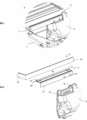
- 3A is an enlarged view of a region A in FIG. 2
- FIG. 3B is an exploded perspective view of FIG. 3A (the main body 7 is not shown).
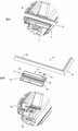
- 4A is an enlarged view of the vicinity of a region A in FIG. 2 viewed from another angle
- FIG. 4B is an exploded perspective view of FIG. 4A.
- FIG. 5A is a cross-sectional view of FIG. 1 taken along a cross-section passing through the right cushioning member 10 in FIG.
- FIG. 6A is an enlarged cross-sectional view of the region C in FIG. 5B, in which the plate-shaped portion 6ua is separated from the engagement groove 2a
- FIG. 6B is a cross-sectional view corresponding to FIG. This shows a state before the member 10 is inserted into the engagement groove 2a.
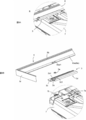
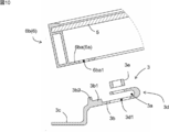
- 7A is an enlarged view of a region B in FIG. 2
- FIG. 7B is an exploded perspective view of FIG. 7A.
- FIG. 8A is an enlarged view of the vicinity of a region B in FIG. 2 viewed from another angle
- FIG. 8B is an exploded perspective view of FIG. 8A.
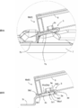
- 9A is a cross-sectional view of FIG.
- FIG. 9B is a cross-sectional view of FIG. FIG. 9B is an exploded view of FIG. 9B.
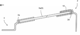
- FIG. 9 is a cross-sectional view illustrating a state where a solar panel 5 is supported by support members 2 and 3 according to a second embodiment of the present invention.
- FIGS. 1 and 2 the structure of the present embodiment includes a float 1, an upper support member 2, a lower support member 3, and a solar panel module 4.
- the upper support member 2 corresponds to a “support member” in the claims.
- the float 1 supports a substantially rectangular solar panel module 4 so that the short side thereof is inclined, and is used, for example, to install the solar panel module 4 on water such as a pond or a lake.
- water such as a pond or a lake.
- the float 1 is manufactured by blow molding in which a cylindrical parison in a molten state is expanded by sandwiching the parison between a plurality of split molds, and has a structure having a hollow portion for storing gas (air or the like) therein.
- various thermoplastic resins can be used as the molding material of the float 1.
- a polyolefin-based resin such as polyethylene or polypropylene can be suitably used.
- the float 1 includes a main body 7 and an upright wall 8.
- the standing wall 8 is provided so as to stand up from the main body 7.
- the float 1 forms a molded body including the main body 7 and the standing wall 8, cuts the remaining sides other than the side 8 a serving as a hinge when the standing wall 8 is raised, and stands on the side 8 a. It can be manufactured by rotating the wall 8 to stand up. At this time, an opening 7c is formed in the main body 7 at the position where the standing wall 8 was formed.
- the solar panel module 4 includes a solar panel 5 and a frame 6 that supports the solar panel.
- the frame 6 has a rectangular shape surrounding the solar panel 5 and includes an upper side 6u, a lower side 6b, a right side 6r, and a left side 61.
- each side is provided with a plate-like portion 6 a extending from the base 6 d toward the inside of the frame 6.
- the base 6d is provided with an engagement recess 6e to which the solar panel 5 can be attached.
- the upper support member 2 is fixed to the upper end of the standing wall 8.
- the plate-like portion 6ua of the upper side 6u is supported by the upper support member 2.
- the upper support member 2 has an engagement groove 2 a that opens toward the outside of the frame 6.
- the plate-shaped portion 6ua is supported by the upper support member 2 by the engagement of the plate-shaped portion 6ua with the engagement groove 2a.
- the upper support member 2 includes an upper wall portion 2b, a side wall portion 2c, and a U-shaped portion 2d.
- the upper wall part 2b and the side wall part 2c are planar, and contact the upper surface 8b and the side surface 8c of the standing wall 8, respectively.
- the U-shaped portion 2d has a U-shape and is provided so as to be continuous with the upper wall portion 2b.
- An engagement groove 2a is provided in the U-shaped portion 2d.
- the upper support member 2 is an elongated member, and the pair of upper support members 2 is fixed to the standing wall 8. Each upper support member 2 is fixed to the standing wall 8 so as to protrude from the standing wall 8. One upper supporting member 2 protrudes to the right of the standing wall 8, and the other upper supporting member 2 protrudes to the left of the standing wall 8.
- the upper support member 2 has a mounting hole 2c1 in the side wall portion 2c, a bolt (not shown) is inserted into the mounting hole 2c1, and the bolt is screwed into an onset nut embedded in the upright wall 8. Thus, it can be fixed to the standing wall 8.
- the plate-shaped portion 6ua is not fixed to the engagement groove 2a, but is relatively movable with respect to the engagement groove 2a. Further, as shown in FIG. 6A, the distance T1A between the inner surfaces of the upper support member 2 in the engagement groove 2a is larger than the thickness T2 of the plate-shaped portion 6ua. The distance T1B between the inner surfaces of the buffer member 10 in the engagement groove 2a is also equal to or greater than the thickness T2 of the plate-shaped portion 6ua. For this reason, the plate-shaped portion 6ua is easily moved relative to the engagement groove 2a.
- the value of T1A / T2 is, for example, 1.2 to 3.0, and specifically, for example, 1.2, 1.4, 1.6, 1.8, 2.0, 2.2,.
- T1B / T2 is, for example, 0.8 to 2.8, and specifically, for example, 0.8, 0.9, 1.0, 1.1, 1.2, 1.4,. 6, 1.8, 2.0, 2.2, 2.4, 2.6, 2.8, and may be in the range between any two of the numerical values exemplified here.
- the cushioning member 10 is a member that can be easily compressed, such as a nonwoven fabric, the plate-shaped portion 6ua moves relative to the engaging groove 2a even when T1B / T2 is 0.8 to 1. Can be made possible.
- the plate-shaped portion 6ua is movably supported by the upper support member 2, so that the plate-shaped portion 6ua is moved relative to the upper support member 2 as the frame 6 expands or contracts. A load is suppressed from being applied to the solar panel module 4 due to the movement.
- the frame 6 and the upper support member 2 are preferably formed of a metal such as aluminum. For this reason, when the plate-shaped portion 6ua relatively moves with respect to the upper support member 2, there is a case where both of them rub and an unpleasant contact sound is generated.
- a buffer member 10 is provided between the upper support member 2 and the plate-shaped portion 6ua.
- the buffer member 10 can be made of a material such as a nonwoven fabric that can suppress the generation of contact noise.
- the upper surface of the plate-shaped portion 6ua is in contact with the buffer member 10 in the engagement groove 2a, and the lower surface of the base 6d is on the upper wall portion 2b outside the engagement groove 2a. It is in contact with the buffer member 10.
- both ends 10a and 10b of the buffer member 10 are fixed to the upper support member 2 at positions that straddle the engagement grooves 2a, and the other portions are not fixed to the upper support member 2.
- both ends 10a and 10b are fixed to the upper surface of the upper wall portion 2b and the upper surface of the U-shaped portion 2d, respectively.
- the cushioning member 10 is engaged by pushing the cushioning member 10 into the engagement groove 2a with the plate-like portion 6ua. It can be arranged in the mating groove 2a.
- the buffer member 10 has an elongated shape.
- a plurality of cushioning members 10 are provided at intervals in the longitudinal direction of the upper support member 2.
- two buffer members 10 are provided at both ends in the longitudinal direction of the upper support member 2.
- the value of (length L1 of each buffer member 10) / (length L2 of upper support member 2) in the longitudinal direction of upper support member 2 is, for example, 0.05 to 0.4. And preferably 0.1 to 0.3, specifically, for example, 0.05, 0.1, 0.2, 0.3, and 0.4. Between the two.
- the lower support member 3 is fixed to the main body 7.
- the plate-like portion 6ba on the lower side 6b is supported by the lower support member 3.
- the lower support member 3 has an engagement groove 3 a that opens toward the outside of the frame 6.
- the plate-shaped portion 6ba is supported by the lower support member 3 by the engagement of the plate-shaped portion 6ba with the engagement groove 3a.
- the lower support member 3 includes an upper portion 3b, a lower portion 3c, and a U-shaped portion 3d.
- the upper section 3b and the lower section 3c are planar and abut on the upper section 7a and the lower section 7b of the step structure provided on the main body 7, respectively.
- the U-shaped portion 3d has a U-shape and is provided so as to be continuous with the upper portion 3b.
- An engagement groove 3a is provided in the U-shaped portion 3d.
- a pedestal portion 3b1 is provided on the upper portion 3b, and a locking projection 3b2 is provided on the pedestal portion 3b1.
- the pedestal portion 3b1 is a portion raised one step, and the locking projection 3b2 is a projection protruding from the pedestal portion 3b1 in an out-of-plane direction.
- the lower side 6b is placed on the pedestal 3b1, and is locked by the locking projection 3b2.
- the lower support member 3 is an elongated member, and the pair of lower support members 3 is fixed to the main body 7. Each lower support member 3 is fixed to the main body 7 so as to protrude from the main body 7. One lower support member 3 protrudes to the right of the main body 7, and the other lower support member 3 protrudes to the left of the main body 7.
- the lower support member 3 has a mounting hole 3c1 in the lower step 3c, a bolt (not shown) is inserted into the mounting hole 3c1, and the bolt is embedded in the lower step 7b. It can be fixed to the main body 7 by screwing it to a nut.
- the plate-shaped portion 6ba is fixed to the engagement groove 3a.
- a through-hole 3d1 is provided through the U-shaped portion 3d.
- the plate-shaped portion 6ba is provided with a through hole 6ba1 at a position facing the through hole 3d1.
- Second Embodiment The structure of a second embodiment of the present invention is similar to the first embodiment, and the main difference is the difference in the structure of the solar panel module 4 and the engagement grooves 2a and 3a. Hereinafter, the differences will be mainly described.
- the solar panel module 4 does not include the frame 6, and the solar panel 5 is directly supported by the support members 2 and 3.
- the engagement grooves 2a and 3a are open toward the inside of the solar panel 5, and the engagement grooves 2a and 3a engage with the plate-shaped portion 5a provided on the solar panel 5.
- the point that the plate portion 5a is relatively movable with respect to the upper support member 2, and the point that the buffer member 10 is disposed between the upper support member 2 and the plate portion 5a are the same as in the first embodiment. .
- the lower support member 3 may be omitted, and the lower end of the solar panel module 4 may be directly supported by the float 1.
- the plate-shaped portion may be supported so as to be relatively movable with respect to the lower support member 3, and a buffer member may be arranged between the lower support member 3 and the plate-shaped portion.
- the plate-shaped part may be fixed to the upper support member 2, or the upper support member 2 may be omitted and the upper end of the solar panel module 4 may be directly supported on the float 1.
Landscapes
- Engineering & Computer Science (AREA)
- Chemical & Material Sciences (AREA)
- Combustion & Propulsion (AREA)
- Mechanical Engineering (AREA)
- Ocean & Marine Engineering (AREA)
- Architecture (AREA)
- Civil Engineering (AREA)
- Structural Engineering (AREA)
- Photovoltaic Devices (AREA)
- Buildings Adapted To Withstand Abnormal External Influences (AREA)
Abstract
フロートの熱膨張・熱収縮によってソーラパネルモジュールに負荷が加わることが抑制可能な構造体を提供する。 本発明によれば、フロートと、支持部材と、ソーラパネルモジュールを備える構造体であって、前記ソーラパネルモジュールは、板状部を備え、前記支持部材は、前記フロートに固定され、かつ前記板状部を支持し、前記板状部は、前記支持部材に対して相対移動可能に支持され、前記支持部材と前記板状部の間に緩衝部材が配置される、構造体が提供される。
Description
本発明は、フロートと、支持部材と、ソーラパネルモジュールを備える構造体に関する。
特許文献1には、ソーラパネルモジュールがフロートに固定された形態が開示されている。
特許文献1では、ソーラパネルモジュールの上端及び下端をフロートに固定しているために、フロートの熱膨張・熱収縮によってソーラパネルモジュールに負荷が加わる。
本発明はこのような事情に鑑みてなされたものであり、フロートの熱膨張・熱収縮によってソーラパネルモジュールに負荷が加わることが抑制可能な構造体を提供するものである。
本発明によれば、フロートと、支持部材と、ソーラパネルモジュールを備える構造体であって、前記ソーラパネルモジュールは、板状部を備え、前記支持部材は、前記フロートに固定され、かつ前記板状部を支持し、前記板状部は、前記支持部材に対して相対移動可能に支持され、前記支持部材と前記板状部の間に緩衝部材が配置される、構造体が提供される。
本発明の構成では、ソーラパネルモジュールの板状部を支持部材に対して移動可能に支持しているので、フロートの熱膨張・熱収縮によってソーラパネルモジュールに負荷が加わることが抑制される。
一方、このような構成では、ソーラパネルモジュールが支持部材に対して相対移動する際に不快な接触音が発生する場合があることが分かった。そこで、支持部材と板状部の間に緩衝部材を配置することによって接触音の発生を抑制することができることを見出し、本発明の完成に到った。
以下、本発明の種々の実施形態を例示する。以下に示す実施形態は互いに組み合わせ可能である。
好ましくは、前記記載の構造体であって、前記支持部材は、前記板状部に係合される係合溝を備え、前記係合溝内で前記板状部が相対移動可能に構成される、構造体である。
好ましくは、前記記載の構造体であって、前記ソーラパネルモジュールは、前記ソーラパネルと、前記ソーラパネルを支持するフレームを備え、前記板状部は、前記フレームに設けられ、前記係合溝は、前記フレームの外側に向いて開いている、構造体である。
好ましくは、前記記載の構造体であって、前記ソーラパネルモジュールは、前記ソーラパネルを備え、前記板状部は、前記ソーラパネルに設けられ、前記係合溝は、前記ソーラパネルの内側に向いて開いている、構造体である。
好ましくは、前記記載の構造体であって、前記係合溝内での前記支持部材の内面間距離が、前記板状部の厚さよりも大きい、構造体である。
好ましくは、前記記載の構造体であって、前記緩衝部材は、前記係合溝の外側において前記支持部材に固定されていて、前記係合溝内では、前記支持部材に固定されていない、構造体である。
好ましくは、前記記載の構造体であって、前記支持部材は、前記フレームの上辺に設けられた前記板状部を支持する、構造体である。
好ましくは、前記記載の構造体であって、前記支持部材は、前記板状部に係合される係合溝を備え、前記係合溝内で前記板状部が相対移動可能に構成される、構造体である。
好ましくは、前記記載の構造体であって、前記ソーラパネルモジュールは、前記ソーラパネルと、前記ソーラパネルを支持するフレームを備え、前記板状部は、前記フレームに設けられ、前記係合溝は、前記フレームの外側に向いて開いている、構造体である。
好ましくは、前記記載の構造体であって、前記ソーラパネルモジュールは、前記ソーラパネルを備え、前記板状部は、前記ソーラパネルに設けられ、前記係合溝は、前記ソーラパネルの内側に向いて開いている、構造体である。
好ましくは、前記記載の構造体であって、前記係合溝内での前記支持部材の内面間距離が、前記板状部の厚さよりも大きい、構造体である。
好ましくは、前記記載の構造体であって、前記緩衝部材は、前記係合溝の外側において前記支持部材に固定されていて、前記係合溝内では、前記支持部材に固定されていない、構造体である。
好ましくは、前記記載の構造体であって、前記支持部材は、前記フレームの上辺に設けられた前記板状部を支持する、構造体である。
以下、本発明の実施形態について説明する。以下に示す実施形態中で示した各種特徴事項は、互いに組み合わせ可能である。また、各特徴事項について独立して発明が成立する。
1.第1実施形態
図1~図10を用いて、本発明の第1実施形態について説明する。図1~図2に示すように、本実施形態の構造体は、フロート1と、上側支持部材2と、下側支持部材3と、ソーラパネルモジュール4を備える。本実施形態では、上側支持部材2が特許請求の範囲の「支持部材」に相当する。
図1~図10を用いて、本発明の第1実施形態について説明する。図1~図2に示すように、本実施形態の構造体は、フロート1と、上側支持部材2と、下側支持部材3と、ソーラパネルモジュール4を備える。本実施形態では、上側支持部材2が特許請求の範囲の「支持部材」に相当する。
<フロート1>
フロート1は、図1に示すように、ほぼ長方形状のソーラパネルモジュール4の短手側を傾斜させるように支持し、例えば、池や湖等の水上にソーラパネルモジュール4を設置するために用いられる。
フロート1は、図1に示すように、ほぼ長方形状のソーラパネルモジュール4の短手側を傾斜させるように支持し、例えば、池や湖等の水上にソーラパネルモジュール4を設置するために用いられる。
フロート1は、溶融状態の筒状のパリソンを複数の分割金型で挟んで膨らますブロー成形によって製造され、内部に気体(空気等)を収容する中空部を有する構造になっている。フロート1の成形材料には、各種の熱可塑性樹脂を使用することができるが、例えば、ポリエチレンやポリプロピレンといったポリオレフィン系樹脂を好適に用いることができる。
図2に示すように、フロート1は、本体部7と、立設壁8を備える。立設壁8は、本体部7から立ち上げるように設けられている。フロート1は、本体部7と立設壁8を含む成形体を形成し、立設壁8を立ち上げる際のヒンジとなる辺8a以外の残りの辺を切断し、辺8aを中心に立設壁8を回動させて立ち上げることによって製造することができる。この際、本体部7には、立設壁8が形成されていた部位に開口部7cが形成される。
<ソーラパネルモジュール4>
図1に示すように、ソーラパネルモジュール4は、ソーラパネル5と、これを支持するフレーム6を備える。フレーム6は、ソーラパネル5取り囲む長方形状であり、上辺6u、下辺6b、右辺6r、左辺6lを備える。図5Bに示すように、各辺には基部6dからフレーム6の内側に向かって延びる板状部6aが設けられている。基部6dには、ソーラパネル5を装着可能な係合凹部6eが設けられている。
図1に示すように、ソーラパネルモジュール4は、ソーラパネル5と、これを支持するフレーム6を備える。フレーム6は、ソーラパネル5取り囲む長方形状であり、上辺6u、下辺6b、右辺6r、左辺6lを備える。図5Bに示すように、各辺には基部6dからフレーム6の内側に向かって延びる板状部6aが設けられている。基部6dには、ソーラパネル5を装着可能な係合凹部6eが設けられている。
<上側支持部材2,緩衝部材10>
図3~図6に示すように、上側支持部材2は、立設壁8の上端に固定されている。上辺6uの板状部6uaが上側支持部材2によって支持されている。上側支持部材2は、フレーム6の外側に向かって開く係合溝2aを有する。板状部6uaが係合溝2aに係合されることによって、板状部6uaが上側支持部材2によって支持される。
図3~図6に示すように、上側支持部材2は、立設壁8の上端に固定されている。上辺6uの板状部6uaが上側支持部材2によって支持されている。上側支持部材2は、フレーム6の外側に向かって開く係合溝2aを有する。板状部6uaが係合溝2aに係合されることによって、板状部6uaが上側支持部材2によって支持される。
上側支持部材2は、上壁部2b、側壁部2c、U字部2dを備える。上壁部2b及び側壁部2cは、平面状であり、それぞれ、立設壁8の上面8b及び側面8cに当接する。U字部2dは、U字状であり、上壁部2bに連なるように設けられる。U字部2dに係合溝2aが設けられる。
上側支持部材2は、細長い部材であり、一対の上側支持部材2が立設壁8に固定される。各上側支持部材2は、立設壁8からはみ出すように立設壁8に固定される。一方の上側支持部材2は、立設壁8の右側にはみ出し、他方の上側支持部材2は、立設壁8の左側にはみ出す。
上側支持部材2は、側壁部2cに取付孔2c1を有し、取付孔2c1にボルト(不図示)を挿入して、このボルトを立設壁8に埋め込まれた鬼目ナットに螺合させることによって立設壁8に固定することができる。
板状部6uaは、係合溝2aに対して固定されておらず、係合溝2aに対して相対移動可能になっている。また、図6Aに示すように、係合溝2a内での上側支持部材2の内面間距離T1Aは、板状部6uaの厚さT2よりも大きい。また、係合溝2a内での緩衝部材10の内面間距離T1Bも板状部6uaの厚さT2以上である。このため、板状部6uaが係合溝2aに対して相対移動しやすくなっている。T1A/T2の値は、例えば1.2~3.0であり、具体的には例えば、1.2、1.4、1.6、1.8、2.0、2.2、2.4、2.6、2.8、3.0であり、ここで例示した数値の何れか2つの間の範囲内であってもよい。T1B/T2の値は、例えば0.8~2.8であり、具体的には例えば、0.8、0.9、1.0、1.1、1.2、1.4、1.6、1.8、2.0、2.2、2.4、2.6、2.8であり、ここで例示した数値の何れか2つの間の範囲内であってもよい。緩衝部材10が不織布のように容易に圧縮可能な部材である場合は、T1B/T2が0.8~1である場合であっても、板状部6uaが係合溝2aに対して相対移動可能にすることができる。
このような構造によって、板状部6uaは、上側支持部材2に対して移動可能に支持されるので、フレーム6の膨張又は収縮に伴って、板状部6uaが上側支持部材2に対して相対移動することによってソーラパネルモジュール4に負荷が加わることが抑制される。
フレーム6及び上側支持部材2は、好ましくは、アルミなどの金属で形成される。このため、板状部6uaが上側支持部材2に対して相対移動する際に両者がこすれて不快な接触音が発生する場合がある。このような接触音の発生を抑制すべく、上側支持部材2と板状部6uaの間には緩衝部材10が設けられている。緩衝部材10は、不織布などの接触音の発生を抑制可能な素材で構成可能である。
なお、図5Bに示すように、係合溝2a内では、板状部6uaの上面が緩衝部材10に当接しており、係合溝2a外では、基部6dの下面が上壁部2b上において緩衝部材10に当接している。
ところで、緩衝部材10を係合溝2a内に貼り付けるのは容易ではない。このため、緩衝部材10は、係合溝2aの外側において上側支持部材2に固定されていて、係合溝2a内では、上側支持部材2に固定されていない。より具体的には、緩衝部材10の両端10a,10bが係合溝2aをまたぐ位置において上側支持部材2に固定されていて、その他の部位は上側支持部材2に固定されていない。本実施形態では、両端10a,10bは、それぞれ、上壁部2bの上面、及びU字部2dの上面に固定される。
図6Bに示すように、緩衝部材10の両端10a,10bを上側支持部材2に固定した状態で、板状部6uaで緩衝部材10を係合溝2a内に押し込むことによって、緩衝部材10を係合溝2a内に配置することができる。
緩衝部材10は、細長い形状である。複数の緩衝部材10が、上側支持部材2の長手方向に間隔を空けて設けられている。本実施形態では、2つの緩衝部材10が上側支持部材2の長手方向の両端に設けられている。図3Bに示すように、上側支持部材2の長手方向についての、(各緩衝部材10の長さL1)/(上側支持部材2の長さL2)の値は、例えば0.05~0.4であり、0.1~0.3が好ましく、具体的には例えば、0.05、0.1、0.2、0.3、0.4であり、ここで例示した数値の何れか2つの間の範囲内であってもよい。このような細長い形状の緩衝部材10を複数設けることによって、緩衝部材10と板状部6uaの間の摩擦を小さくしつつ、板状部6uaと上側支持部材2が直接接触することが抑制されている。
<下側支持部材3>
図7~図10に示すように、下側支持部材3は、本体部7に固定されている。下辺6bの板状部6baが下側支持部材3によって支持されている。下側支持部材3は、フレーム6の外側に向かって開く係合溝3aを有する。板状部6baが係合溝3aに係合されることによって、板状部6baが下側支持部材3によって支持される。
図7~図10に示すように、下側支持部材3は、本体部7に固定されている。下辺6bの板状部6baが下側支持部材3によって支持されている。下側支持部材3は、フレーム6の外側に向かって開く係合溝3aを有する。板状部6baが係合溝3aに係合されることによって、板状部6baが下側支持部材3によって支持される。
下側支持部材3は、上段部3b、下段部3c、U字部3dを備える。上段部3b及び下段部3cは、平面状であり、それぞれ、本体部7に設けられた段差構造の上段7a及び下段7bに当接する。U字部3dは、U字状であり、上段部3bに連なるように設けられる。U字部3dに係合溝3aが設けられる。
図9~図10に示すように、上段部3bには、台座部3b1が設けられており、台座部3b1には、係止突起3b2が設けられている。台座部3b1は、一段高くなった部位であり、係止突起3b2は台座部3b1から面外方向に突出する突起である。下辺6bは台座部3b1上に載置され、係止突起3b2によって係止される。
下側支持部材3は、細長い部材であり、一対の下側支持部材3が本体部7に固定される。各下側支持部材3は、本体部7からはみ出すように本体部7に固定される。一方の下側支持部材3は、本体部7の右側にはみ出し、他方の下側支持部材3は、本体部7の左側にはみ出す。
図7Bに示すように、下側支持部材3は、下段部3cに取付孔3c1を有し、取付孔3c1にボルト(不図示)を挿入して、このボルトを下段7bに埋め込まれた鬼目ナットに螺合させることによって本体部7に固定することができる。
図8~図9に示すように、板状部6baは、係合溝3aに対して固定されている。下側支持部材3が本体部7からはみ出した位置には、U字部3dを貫く貫通孔3d1が設けられている。また、板状部6baには、貫通孔3d1に対向する位置に貫通孔6ba1が設けられている。図9Bに示すように、下辺6bを台座部3b1上に載置させ、かつ係止突起3b2に当接させた状態で、U字部3dの下面3d3側から、貫通孔3d1,6ba1にボルト(不図示)を差し込んで、U字部3dの上面3d2に配置したナット3eに螺合させることによって、板状部6baを係合溝3aに固定することができる。
2.第2実施形態
本発明の第2実施形態の構造体は、第1実施形態に類似しており、ソーラパネルモジュール4と、係合溝2a,3aの構造の違いが主な相違点である。以下、相違点を中心に説明する。
本発明の第2実施形態の構造体は、第1実施形態に類似しており、ソーラパネルモジュール4と、係合溝2a,3aの構造の違いが主な相違点である。以下、相違点を中心に説明する。
本実施形態では、ソーラパネルモジュール4がフレーム6を備えず、ソーラパネル5が支持部材2,3によって直接支持される。
係合溝2a,3aは、ソーラパネル5の内側に向かって開いており、係合溝2a,3aは、ソーラパネル5に設けられた板状部5aに係合する。板状部5aが上側支持部材2に対して相対移動可能である点、及び上側支持部材2と板状部5aの間に緩衝部材10が配置される点は、第1実施形態と同様である。
3.その他実施形態
・下側支持部材3を省略して、ソーラパネルモジュール4の下端をフロート1に直接支持させるようにしてもよい。
・板状部が下側支持部材3に対して相対移動可能に支持され、下側支持部材3と板状部の間に緩衝部材が配置されるように構成してもよい。この場合、板状部は上側支持部材2に対して固定してもよく、上側支持部材2を省略してソーラパネルモジュール4の上端をフロート1に直接支持させるようにしてもよい。
・下側支持部材3を省略して、ソーラパネルモジュール4の下端をフロート1に直接支持させるようにしてもよい。
・板状部が下側支持部材3に対して相対移動可能に支持され、下側支持部材3と板状部の間に緩衝部材が配置されるように構成してもよい。この場合、板状部は上側支持部材2に対して固定してもよく、上側支持部材2を省略してソーラパネルモジュール4の上端をフロート1に直接支持させるようにしてもよい。
1:フロート、2:上側支持部材、2a:係合溝、2b:上壁部、2c:側壁部、2c1:取付孔、2d:U字部、3:下側支持部材、3a:係合溝、3b:上段部、3b1:台座部、3b2:係止突起、3c:下段部、3c1:取付孔、3d:U字部、3d1:貫通孔、3d2:上面、3d3:下面、3e:ナット、4:ソーラパネルモジュール、5:ソーラパネル、5a:板状部、6:フレーム、6a:板状部、6b:下辺、6ba:板状部、6ba1:貫通孔、6d:基部、6e:係合凹部、6l:左辺、6r:右辺、6u:上辺、6ua:板状部、7:本体部、7a:上段、7b:下段、7c:開口部、8:立設壁、8a:辺、8b:上面、8c:側面、10:緩衝部材、10a:端、10b:端
Claims (7)
- フロートと、支持部材と、ソーラパネルモジュールを備える構造体であって、
前記ソーラパネルモジュールは、板状部を備え、
前記支持部材は、前記フロートに固定され、かつ前記板状部を支持し、
前記板状部は、前記支持部材に対して相対移動可能に支持され、
前記支持部材と前記板状部の間に緩衝部材が配置される、構造体。 - 請求項1に記載の構造体であって、
前記支持部材は、前記板状部に係合される係合溝を備え、
前記係合溝内で前記板状部が相対移動可能に構成される、構造体。 - 請求項2に記載の構造体であって、
前記ソーラパネルモジュールは、前記ソーラパネルと、前記ソーラパネルを支持するフレームを備え、
前記板状部は、前記フレームに設けられ、
前記係合溝は、前記フレームの外側に向いて開いている、構造体。 - 請求項2に記載の構造体であって、
前記ソーラパネルモジュールは、前記ソーラパネルを備え、
前記板状部は、前記ソーラパネルに設けられ、
前記係合溝は、前記ソーラパネルの内側に向いて開いている、構造体。 - 請求項2~請求項4の何れか1つに記載の構造体であって、
前記係合溝内での前記支持部材の内面間距離が、前記板状部の厚さよりも大きい、構造体。 - 請求項2~請求項5の何れか1つに記載の構造体であって、
前記緩衝部材は、前記係合溝の外側において前記支持部材に固定されていて、前記係合溝内では、前記支持部材に固定されていない、構造体。 - 請求項1~請求項6の何れか1つに記載の構造体であって、
前記支持部材は、前記フレームの上辺に設けられた前記板状部を支持する、構造体。
Priority Applications (2)
| Application Number | Priority Date | Filing Date | Title |
|---|---|---|---|
| US17/251,933 US12103647B2 (en) | 2018-06-25 | 2019-06-19 | Solar panel module fixed to a float |
| CN201980028759.1A CN112041223B (zh) | 2018-06-25 | 2019-06-19 | 结构体 |
Applications Claiming Priority (2)
| Application Number | Priority Date | Filing Date | Title |
|---|---|---|---|
| JP2018-120239 | 2018-06-25 | ||
| JP2018120239A JP7082283B2 (ja) | 2018-06-25 | 2018-06-25 | 構造体及びその製造方法 |
Publications (1)
| Publication Number | Publication Date |
|---|---|
| WO2020004180A1 true WO2020004180A1 (ja) | 2020-01-02 |
Family
ID=68987098
Family Applications (1)
| Application Number | Title | Priority Date | Filing Date |
|---|---|---|---|
| PCT/JP2019/024313 Ceased WO2020004180A1 (ja) | 2018-06-25 | 2019-06-19 | 構造体 |
Country Status (5)
| Country | Link |
|---|---|
| US (1) | US12103647B2 (ja) |
| JP (1) | JP7082283B2 (ja) |
| CN (1) | CN112041223B (ja) |
| TW (1) | TWI796495B (ja) |
| WO (1) | WO2020004180A1 (ja) |
Cited By (1)
| Publication number | Priority date | Publication date | Assignee | Title |
|---|---|---|---|---|
| US11949371B2 (en) | 2020-12-23 | 2024-04-02 | Array Technologies, Inc. | Photovoltaic module deflection limiter |
Citations (5)
| Publication number | Priority date | Publication date | Assignee | Title |
|---|---|---|---|---|
| JP2002173083A (ja) * | 2000-12-05 | 2002-06-18 | Shin Kobe Electric Mach Co Ltd | 太陽電池搭載用フロートならびに太陽電池装置 |
| JP2003209274A (ja) * | 2002-01-11 | 2003-07-25 | Jfe Steel Kk | 水上設置用太陽電池発電装置 |
| JP2014511043A (ja) * | 2011-04-15 | 2014-05-01 | シエル エ テール アンテルナシオナル | パネル支持装置 |
| CN107733325A (zh) * | 2017-09-11 | 2018-02-23 | 中国十七冶集团有限公司 | 一种水上漂浮光伏电站的基台及其安装方法 |
| JP2018030588A (ja) * | 2015-11-27 | 2018-03-01 | 三井住友建設株式会社 | 太陽光パネル設置用浮き架台製造方法 |
Family Cites Families (7)
| Publication number | Priority date | Publication date | Assignee | Title |
|---|---|---|---|---|
| JP3397637B2 (ja) * | 1997-06-11 | 2003-04-21 | キヤノン株式会社 | 太陽電池一体型屋根板、その製造方法、及びその施工方法 |
| JP2006100392A (ja) * | 2004-09-28 | 2006-04-13 | Msk Corp | パネル保持機構 |
| WO2008041298A1 (fr) * | 2006-09-29 | 2008-04-10 | Mitsubishi Heavy Industries, Ltd. | Panneau solaire |
| US20140060625A1 (en) * | 2012-09-05 | 2014-03-06 | Ppg Industries Ohio, Inc. | Solar module frame |
| PH12016502278B1 (en) | 2014-05-16 | 2023-03-01 | Kyoraku Co Ltd | Solar panel float and connected body thereof |
| JP6712054B2 (ja) | 2016-07-29 | 2020-06-17 | キョーラク株式会社 | ソーラパネル用の樹脂製のフロート及びそのフロートの製造方法 |
| CN108183667B (zh) * | 2018-01-08 | 2023-11-17 | 盛和众诚(北京)新能源科技有限公司 | 水上光伏板的支撑装置 |
-
2018
- 2018-06-25 JP JP2018120239A patent/JP7082283B2/ja active Active
-
2019
- 2019-06-19 WO PCT/JP2019/024313 patent/WO2020004180A1/ja not_active Ceased
- 2019-06-19 US US17/251,933 patent/US12103647B2/en active Active
- 2019-06-19 CN CN201980028759.1A patent/CN112041223B/zh active Active
- 2019-06-21 TW TW108121687A patent/TWI796495B/zh active
Patent Citations (5)
| Publication number | Priority date | Publication date | Assignee | Title |
|---|---|---|---|---|
| JP2002173083A (ja) * | 2000-12-05 | 2002-06-18 | Shin Kobe Electric Mach Co Ltd | 太陽電池搭載用フロートならびに太陽電池装置 |
| JP2003209274A (ja) * | 2002-01-11 | 2003-07-25 | Jfe Steel Kk | 水上設置用太陽電池発電装置 |
| JP2014511043A (ja) * | 2011-04-15 | 2014-05-01 | シエル エ テール アンテルナシオナル | パネル支持装置 |
| JP2018030588A (ja) * | 2015-11-27 | 2018-03-01 | 三井住友建設株式会社 | 太陽光パネル設置用浮き架台製造方法 |
| CN107733325A (zh) * | 2017-09-11 | 2018-02-23 | 中国十七冶集团有限公司 | 一种水上漂浮光伏电站的基台及其安装方法 |
Cited By (1)
| Publication number | Priority date | Publication date | Assignee | Title |
|---|---|---|---|---|
| US11949371B2 (en) | 2020-12-23 | 2024-04-02 | Array Technologies, Inc. | Photovoltaic module deflection limiter |
Also Published As
| Publication number | Publication date |
|---|---|
| JP2020001466A (ja) | 2020-01-09 |
| US20210261225A1 (en) | 2021-08-26 |
| US12103647B2 (en) | 2024-10-01 |
| TWI796495B (zh) | 2023-03-21 |
| CN112041223B (zh) | 2023-06-09 |
| TW202017808A (zh) | 2020-05-16 |
| JP7082283B2 (ja) | 2022-06-08 |
| CN112041223A (zh) | 2020-12-04 |
Similar Documents
| Publication | Publication Date | Title |
|---|---|---|
| CN109068864B (zh) | 长合成树脂泡沫体 | |
| KR102048785B1 (ko) | 친환경 복합 커튼월 | |
| CN110450384B (zh) | 吹塑成型肋结构 | |
| JP2020001466A (ja) | 構造体及びその製造方法 | |
| US4608744A (en) | Frame molding process of a seat for vehicles | |
| US7828113B1 (en) | Methods and apparatus for controlling vibration of enclosures, particularly loudspeaker enclosures | |
| US10294018B2 (en) | Appliance shipping runner | |
| JP2006020742A (ja) | 組立ラック | |
| KR20150090907A (ko) | 차량용 도어 빔 | |
| JP6255710B2 (ja) | 天井及び壁の少なくともどちらかに断熱・緩衝機能を有する面材を備えた簡易建築物における前記面材の取付方法 | |
| KR200478169Y1 (ko) | 유니버셜 프로파일 너트 | |
| JP6819505B2 (ja) | スピーカシステム及び車両ドア | |
| JP4959308B2 (ja) | ロッキング対応の外装材取付構造 | |
| KR102610745B1 (ko) | 배기계용 탄성지지구 | |
| KR20190023443A (ko) | 창호 설치용 브라켓 | |
| EP4051849B1 (en) | Floor support device and floor support system | |
| US10259411B2 (en) | Weight-reducing surface structuring on components produced by a casting method | |
| JPH1088719A (ja) | 窓枠支持装置 | |
| JP2018031219A (ja) | 板状断熱材及び断熱パネル | |
| JP2015143444A (ja) | 建築用受具 | |
| KR101564427B1 (ko) | 거푸집 틈새 매움용 필러 | |
| JP5725819B2 (ja) | 外装材と外装構造 | |
| JP2009234313A (ja) | バンパー構造 | |
| JP3182458U (ja) | 係合構造 | |
| JP2007009449A (ja) | エキスパンションジョイント |
Legal Events
| Date | Code | Title | Description |
|---|---|---|---|
| 121 | Ep: the epo has been informed by wipo that ep was designated in this application |
Ref document number: 19826172 Country of ref document: EP Kind code of ref document: A1 |
|
| NENP | Non-entry into the national phase |
Ref country code: DE |
|
| 122 | Ep: pct application non-entry in european phase |
Ref document number: 19826172 Country of ref document: EP Kind code of ref document: A1 |