WO2020003979A1 - パッド部材を備えたロボットハンド - Google Patents
パッド部材を備えたロボットハンド Download PDFInfo
- Publication number
- WO2020003979A1 WO2020003979A1 PCT/JP2019/022813 JP2019022813W WO2020003979A1 WO 2020003979 A1 WO2020003979 A1 WO 2020003979A1 JP 2019022813 W JP2019022813 W JP 2019022813W WO 2020003979 A1 WO2020003979 A1 WO 2020003979A1
- Authority
- WO
- WIPO (PCT)
- Prior art keywords
- pad
- main body
- robot hand
- hand
- flange
- Prior art date
- Legal status (The legal status is an assumption and is not a legal conclusion. Google has not performed a legal analysis and makes no representation as to the accuracy of the status listed.)
- Ceased
Links
Images



Classifications
-
- B—PERFORMING OPERATIONS; TRANSPORTING
- B25—HAND TOOLS; PORTABLE POWER-DRIVEN TOOLS; MANIPULATORS
- B25J—MANIPULATORS; CHAMBERS PROVIDED WITH MANIPULATION DEVICES
- B25J15/00—Gripping heads and other end effectors
- B25J15/06—Gripping heads and other end effectors with vacuum or magnetic holding means
-
- H—ELECTRICITY
- H10—SEMICONDUCTOR DEVICES; ELECTRIC SOLID-STATE DEVICES NOT OTHERWISE PROVIDED FOR
- H10P—GENERIC PROCESSES OR APPARATUS FOR THE MANUFACTURE OR TREATMENT OF DEVICES COVERED BY CLASS H10
- H10P72/00—Handling or holding of wafers, substrates or devices during manufacture or treatment thereof
- H10P72/30—Handling or holding of wafers, substrates or devices during manufacture or treatment thereof for conveying, e.g. between different workstations
Definitions
- the present invention relates to a robot hand including a pad member for holding a substrate.
- a transfer robot that holds and transfers a wafer has been used.
- This transfer robot has a hand connected to the tip of an arm.
- the hand holds the back surface of the wafer on its upper surface, and transfers the wafer to a cassette or the like that stores the wafer.
- the hands of these transfer robots have a holding unit for holding a wafer.
- the holding portion may be formed by directly shaving a member constituting the hand, or may be mounted on the hand with a pad formed of an elastic material such as natural rubber or synthetic rubber.
- Patent Document 1 discloses a mounting portion connected to an end of a robot arm through an opening, a root portion following the mounting portion, and integrally connected from the root portion. And a suction pad having a skirt portion.
- the root has a substantially circular cross section, and its outer periphery gradually increases in diameter and continues to the skirt.
- the skirt has a substantially circular cross section larger than the root, and the skirt from the starting point to the end of the skirt gradually becomes thinner from the starting point to the end of the skirt and is integrally formed.
- a through hole extending from the bottom surface of the skirt portion to the opening is provided substantially at the center of a surface of the skirt portion that contacts the workpiece on the inner bottom surface.
- Patent Document 2 discloses a vacuum suction pad attached to a first mounting hole formed in a transfer arm of a substrate transfer device, connected to a vacuum suction path of the transfer arm, and vacuum-sucking a substrate to the transfer arm. I have.
- Patent Document 1 reduces the contact portion with the workpiece by increasing the thickness of the skirt portion.
- the contact area between the suction pad and the work tends to be smaller and smaller, and a response is required.
- the vacuum suction pad of Patent Document 2 is attached to the mounting hole of the transfer arm via a seal member, and the seal member ensures airtightness. Therefore, when the vacuum suction pad is replaced, the seal member also needs to be replaced, and the replacement of the vacuum suction pad becomes complicated.
- the present invention has been made in view of the above points, and when a wafer is placed and held on a robot hand, stable holding is enabled, and replacement work such as attachment and removal of a pad member is facilitated. Provide a robot hand that can do it.
- the robot hand of the present invention A robot hand attached to a robot arm for transferring a substrate and holding the substrate, A hand body, A pad member attached to an opening provided in the hand main body and holding the substrate, The pad member, A pad body attached to the opening and having a through hole in the center thereof, A first ring portion provided on the tip side of the pad member and abutting on the substrate; A first flange portion provided integrally with the first ring portion and the pad body portion and extending toward the outside of the pad body portion.
- the pad can be inserted into the opening of the hand main body, which is the pad mounting hole, while the pad is deformed so as to be crushed, so that the work of attaching and removing the pad from the opening becomes easy.
- the pad member A second ring portion provided on the rear end side of the pad member and formed in the same shape as the first ring portion; A second flange portion provided integrally with the second ring portion and the pad body portion and seated on the hand body portion may be further provided.
- first ring portion and the second ring portion have a symmetrical structure, either the first ring portion or the second ring portion may be the side that comes into contact with the substrate. Furthermore, erroneous installation when attaching the pad to the robot hand can be prevented, and the ease of attaching the pad can be enhanced.
- the pad member may further include a third flange provided integrally with the pad body at a rear end side thereof and extending toward the outside of the pad body.
- the pad can be easily attached to the opening of the robot hand.
- the hand main body may have a passage therein, one end of which is communicated with the opening, and the other end of which is connected to a suction / exhaust unit.
- the suction / exhaust unit when the cycle time is insufficient without suction, for example, the suction / exhaust unit is separately provided, and the vacuum transfer is performed through the vacuum suction path, so that the transfer can be reliably performed while holding the substrate. Becomes possible.
- the pad body is a cylindrical member
- the first flange portion may have a tapered portion that increases in diameter from the first ring portion side to the pad body portion side.
- the second flange portion may have a tapered portion that increases in diameter from the second ring portion side to the pad body portion side.
- the pad can be easily attached to the opening of the robot hand.
- the pad member may be attached to the hand main body by holding the hand main body between the first flange and the second flange.
- the pad member may be attached to the hand main body by holding the hand main body between the first flange and the third flange.
- the pad member may be made of a conductive resin obtained by dispersing conductive particles in a resin composition.
- An outer diameter of the first ring portion may be formed to be smaller than an outer diameter of the pad body.
- the contact area between the substrate and the contact surface (the first ring portion) of the pad can be reduced, so that adhesion of particles to the substrate due to contact of the pad with the substrate is suppressed. be able to.
- a robot hand which can stably hold a wafer when the wafer is placed and held on the robot hand, and which can easily perform replacement work such as mounting and removing a pad member. it can.
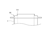
- FIG. 4 is a sectional view taken along line IV-IV of FIG. 3. It is a perspective view showing an example of the robot hand concerning the present invention.
- FIG. 6 is a sectional view taken along line VI-VI of FIG. 5. It is sectional drawing which shows the modification of the pad which concerns on this invention. It is a partial enlarged front view showing a modification of the pad concerning the present invention. It is a partial enlarged front view showing a modification of the pad concerning the present invention. It is a partial enlarged front view showing a modification of the pad concerning the present invention. It is a partial enlarged front view showing a modification of the pad concerning the present invention.
- a pad 1 (an example of a pad member) according to the embodiment will be described with reference to FIGS.
- the pad 1 is used, for example, as a component that holds a wafer (an example of a substrate) that is a material for manufacturing a semiconductor device.
- the pad 1 is used by being attached to a hand (hereinafter, referred to as a robot hand) connected to the tip of an arm (an example of a robot arm) of an industrial robot, for example, a wafer transfer robot for transferring wafers between facilities. Can be done. Details of the robot hand will be described later.
- the pad 1 is provided at a main body (pad main body) 2 provided at a central portion and at both ends in a height direction (a vertical direction in FIG. 2) of the main body 2.
- the holding portion 3 in the present embodiment includes a first holding portion 3A provided at one end portion (for example, an upper end portion in FIGS. 2 and 4) of the main body portion 2 and an end portion opposite to the first holding portion 3A. (For example, a lower end portion in FIGS. 2 and 4).
- the main body 2 and the holding parts 3A, 3B are formed integrally.
- the main body 2 is a cylindrical member.
- the height of the main body 2 is set, for example, to be substantially the same as the thickness (the vertical height in FIG. 6) of the hand main body 110 at an opening 101 (see FIG. 6) described later.
- the height of the main body 2 is, for example, about 1 to 2 mm.
- the outer diameter R1 of the main body 2 is formed to be the same as or slightly larger than the inner diameter of an opening 101 (see FIG. 6) described later.
- the outer diameter R1 of the main body 2 is formed slightly larger than the same diameter as the inner diameter of the opening 101.
- a through hole 5 is formed at the center of the main body 2 and at the center of the holder 3 (3A, 3B) so as to communicate the main body 2 with the holder 3 (3A, 3B).
- the through hole 5 in this embodiment has a circular cross section and a uniform diameter in the height direction of the pad 1.
- the holding unit 3 (3A, 3B) has a ring 31 (31A, 31B) that comes into contact with the wafer or the like when the wafer or the like as the target member is held (placed).
- the ring portion 31 (31A, 31B) is formed in an annular shape at the edge of the through hole 5.
- the ring 31A and the ring 31B may have substantially the same shape.
- the ring portion 31A and the ring portion 31B are formed in an annular shape having the same diameter.
- the outer diameter R2 of the ring 31 (31A, 31B) is formed to be smaller than the outer diameter R1 of the main body 2.
- the outer diameter R2 of the ring portion 31 (31A, 31B) is formed slightly larger than the diameter R4 of the through hole 5 (see FIG. 4).
- the ring portion 31 (31A, 31B) is formed to be substantially flat so as to be orthogonal to the height direction of the main body 2. The wafer is held in a state of being in contact with one of the ring portion 31A (an example of a first ring portion) of the first holding portion 3A and the ring portion 31B (an example of the second ring portion) of the second holding portion 3B. Is done.
- the holding portion 3 (3A, 3B) is provided between the ring portion 31 (31A, 31B) and the main body portion 2 with a flange portion 32 (1) provided integrally with the main body portion 2 and the ring portion 31 (31A, 31B). 32A, 32B).
- the flange 32 (32A, 32B) includes a tapered portion 33 (33A, 33B) and a seating surface 34 (34A, 34B).
- the tapered portion 33 (33A, 33B) is formed so as to increase in diameter from the ring portion 31 (31A, 31B) side toward the main body portion 2 side.
- the seating surface 34 is formed in a portion of the flange 32 (32A, 32B) in contact with the main body 2, and is formed in parallel with a plane orthogonal to the height direction of the main body 2. That is, the outer diameter R3 of the flange 32 (32A, 32B) is formed to be larger than the outer diameter R1 of the main body 2.
- the seating surface 34 (34A, 34B) is a surface that contacts a part of the robot hand 100 when the pad 1 is attached to the robot hand 100.
- the holding portions 3 are formed in a truncated cone shape.
- the first holding portion 3A provided at the upper end of the main body 2 is formed so that the diameter decreases toward the ring portion 31A.
- the second holding portion 3B provided at the lower end of the main body 2 is formed such that the diameter decreases toward the ring portion 31B.
- the first holding portion 3A and the second holding portion 3B are formed so as to have a symmetrical structure with the main body 2 therebetween.
- the bottom view of the pad 1 is the same as the plan view shown in FIG.
- the rear view and the left and right side views of the pad 1 are the same as the front view shown in FIG.
- the area of the ring portion 31 (31A, 31B) is formed to be, for example, 0.1 to 1 square millimeter (mm 2 ) or less. If the area of the ring portion 31 (31A, 31B) is less than 0.1 mm 2 , there is a possibility that poor contact with the wafer may occur. On the other hand, if the area of the ring portion 31 (31A, 31B) is larger than 1 mm 2, there is a possibility that particles adhere to the wafer. For example, when the diameter R4 of the through hole 5 is 4 mm, the radial width W of the ring portion 31 (31A, 31B) is formed to be 0.01 mm to 0.065 mm.
- the area of the ring 31 (31A, 31B) varies depending on the total allowable contact area S between all the pads 1 attached to the robot hand 100 and the wafer, that is, the number of the pads 1. Assuming that the total allowable contact area S between all the pads 1 and the wafer is constant, as the number of the pads 1 increases to one, two, three,... 31A, 31B) are reduced to S, S / 2, S / 3,... In other words, when the allowable total contact area S between all the pads 1 and the wafer is determined and the number of all the pads 1 attached to the robot hand 100 is determined, the ring portion 31 (31A, 31B) Is uniquely determined.
- the total contact area S is 3 mm 2 or less
- the total number of pads 1 is three
- the diameter R4 of the through hole 5 is 4 mm
- the outer diameter R2 of the ring 31 (31A, 31B) is 4.13 mm.
- the radial width W of the ring portion 31 (31A, 31B) is 0.065 mm.
- the area of the ring portions 31 (31A, 31B) is 0.83 mm 2
- the total area of the ring portion 31 satisfies 2.49 2
- the total contact area S a (3 mm 2 or less).
- the total contact area S is 0.5 mm 2 or less
- the total number of pads 1 is 3
- the diameter R4 of the through hole 5 is 4 mm
- the outer diameter R2 of the ring portions 31 (31A, 31B) is 4.02 mm.
- the radial width W of the ring portion 31 (31A, 31B) is 0.01 mm. In this case, satisfying the ring portion 31 (31A, 31B) area of 0.13 mm 2, the total area of 0.39 mm 2 next to the ring portion 31, the contact total area S (0.5 mm 2 or less).
- the main body 2 and the holding parts 3 (3A, 3B) constituting the pad 1 are made of a conductive resin obtained by dispersing conductive particles in a resin composition.
- the main body 2 and the holding parts 3 (3A, 3B) can be made of, for example, a fluororesin such as polytetrafluoroethylene, perfluoroalkoxyalkane, ethylene tetrafluoroethylene copolymer, or the like.
- a fluororesin such as polytetrafluoroethylene, perfluoroalkoxyalkane, ethylene tetrafluoroethylene copolymer, or the like.
- As the resin composition all other resins commonly used for pads of robot hands for handling semiconductor wafers can be applied.
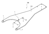
- FIG. 5 is a perspective view showing the robot hand 100 including the pad 1.
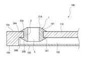
- FIG. 6 is a sectional view of the robot hand 100 taken along the line VI-VI.
- the robot hand 100 is provided with a plurality (three in this embodiment) of pads 1 for holding a wafer at its tip. Further, the robot hand 100 includes a suction / exhaust unit (not shown), and each pad 1 is connected to the suction / exhaust unit via a passage 102 described later.
- the pad 1 attached to the robot hand 100 holds the wafer and the like so that the wafer and the like do not shift with respect to the robot hand 100 or drop from the robot hand 100 by vacuum-sucking the wafer.
- the robot hand 100 is made of, for example, a ceramic material such as alumina.
- the robot hand 100 has a hand main body 110, an opening 101 for attaching the pad 1, and a passage 102 (a part of the intake / exhaust unit) communicating with the opening 101.
- the opening 101 is a hole formed in a holding surface 103 (upper surface in FIG. 6) which is a surface of the hand main body 110 on which a wafer or the like is held, and is communicated with the passage 102.
- the opening 101 in the present embodiment has a circular cross section and a uniform diameter in the thickness direction of the hand main body 110 at the opening 101.
- the diameter of the opening 101 is formed to be substantially the same as or slightly smaller than the outer diameter R1 of the main body 2.
- the passage portion 102 is formed by sealing a groove formed on a surface (back surface) 104 of the hand main body 110 opposite to the holding surface 103 with a lid member (seal member) 105.
- An end (the right end in FIG. 6) of the passage 102 is connected to a suction / exhaust unit (not shown).
- One of the holding portions 3 (3A or 3B) of the pad 1 is inserted into the opening 101 from the holding surface 103 side of the hand main body 110 while being elastically deformed.
- the flange portion 32 (32A, 32B) includes the tapered portion 33 (33A, 33B)
- the holding portion 3 (3A or 3B) is guided into the opening portion 101 while being self-aligned.
- the largest diameter portion 321 (see FIG. 6) of the flange portion 32 (32A, 32B) is elastically deformed while being folded toward the main body portion 2 and elastically deformed to the original shape after completely passing through the opening 101.
- the holding portion 3 (3A or 3B) comes into close contact with the lower edge of the opening 101.
- the flange 32B (tapered portion 33B) of the second holding portion 3B enters the opening 101, and the second holding portion 3B (the ring portion 31B and the flange 32B). ) are arranged in the passage portion 102.
- the seating surface 34B of the second holding portion 3B arranged in the passage portion 102 abuts (sits) on the inner wall surface of the passage portion 102 (the upper surface of the passage portion 102 in FIG. 6).
- the main body 2 of the pad 1 is in contact with the inner peripheral surface of the opening 101, and both are in close contact with each other.
- the first holding portion 3A is not inserted into the opening 101, but is arranged outside the opening 101 (above the holding surface 103 in FIG. 6), and the seating surface 34A of the first holding portion 3A is It is attached in a state where it abuts on 103. That is, the pad 1 is securely attached to the hand main body 110 by holding the hand main body 110 between the flange 32A of the first holding part 3A and the flange 32B of the second holding part 3B.
- the mounting position of the pad 1 attached to the robot hand 100 is defined by the flange portion 32A of the first holding portion 3A and the flange portion 32B of the second holding portion 3B at an appropriate position.
- the through hole 5 of the pad 1 and the passage 102 of the robot hand 100 are communicated.
- the air in the through-hole 5 and the passage portion 102 is evacuated by the operation of the suction / exhaust unit, so that the wafer placed on the robot hand 100 is vacuum-sucked on the ring portion 31A of the pad 1. .
- the robot hand 100 includes the hand main body 110 and the pad 1 attached to the opening 101 provided in the hand main body 110 and holding a wafer.
- the pad 1 is attached to the opening 101 and has a through-hole 5 at the center thereof, a main body 2 (an example of a pad main body), rings 31 provided at both ends of the pad 1, a ring 31 and a main body.
- a flange portion 32 provided integrally with the portion 2 and extending toward the outside of the main body portion 2.
- the outer diameter R2 of the ring portion 31 is formed to be smaller than the outer diameter R1 of the main body portion 2.
- the pad 1 can be attached to the robot hand 100 simply by inserting the pad 1 into the opening 101 of the hand main body 110, which is a pad attachment hole, while deforming the pad 1 so as to crush it. For this reason, a special instrument or member is not required when attaching and detaching the pad 1 to and from the opening 101. Therefore, the attachment / detachment operation is easy, and the cost of members associated with the attachment / detachment is zero.
- the pad 1 is made of a resin composition containing conductive particles, the pad 1 is brought into contact with the wafer to ground the static electricity charged on the wafer. As a result, there is no possibility that a spark will occur between the pad 1 and the wafer. As a result, there is no risk of damage to the wafer, and the yield of the wafer is improved.
- the ring 31 is provided with a ring 31A (an example of a first ring) provided on the front end side of the pad 1 and a ring provided on the rear end side of the pad 1.
- the flange portion 32 includes a ring portion 31B (an example of a second ring portion) formed in the same shape as the portion 31A, and the flange portion 32 is provided integrally with the ring portion 31A and the main body portion 32 (first flange portion 32A).
- a flange portion) and a flange portion 32B (an example of a second flange portion) provided integrally with the ring portion 31B and the main body portion 2.
- the ring portion 31A and the ring portion 31B have a symmetric structure, either the ring portion 31A or the ring portion 31B may be on the side that comes into contact with the wafer. Furthermore, since the flange 32A and the flange 32B also have a symmetrical structure, erroneous installation when mounting the pad 1 on the robot hand 100 can be prevented, and the mounting of the pad 1 is easy.
- the hand main body 110 has a passage portion 102 in which one end is communicated with the opening 101 and the other end is connected to the intake / exhaust unit. . Accordingly, if the wafer is transferred without being sucked to the pad and the cycle time of the wafer transfer is insufficient or the suction force is insufficient, the suction and exhaust unit is separately provided and the passage unit 102 is provided. By evacuating the wafer, it is possible to transfer the wafer while securely holding the wafer.
- the hand main body 110 when the pad 1 is attached to the hand main body 110, the hand main body 110 is sandwiched between the flange 32A and the flange 32B, and the pad 1 is securely attached to the hand main body 110. It is held in close contact. Thereby, it is possible to prevent the pad 1 from dropping from the robot hand 100.
- the pad 1 when the pad 1 is worn by use, it is not necessary to replace the robot hand 100 itself, and only the pad 1 needs to be attached and replaced. In addition, no special tools or members are required for the replacement, and it can be easily removed and attached by hand. Further, the pad 1 is free from the front and back when the pad is first attached. After the pad 1 is first attached and the front side is used, the pad 1 is once removed and the opposite back side (the side located in the passage portion 102) is removed. Can be reused. Therefore, the time required for the replacement work can be significantly reduced, and there is no cost for the members required for replacement, and one pad 1 can be used twice.
- the pad 1 when the pad 1 is attached to the robot hand 100, it is not necessary to attach a sealing member or the like such as a vacuum suction pad disclosed in Patent Document 2, for example. 1 can be easily replaced.
- the holding portion 3 including the ring portion 31 and the flange portion 32 is provided at both ends of the main body portion 2.
- the holding portion 3 may be configured to be provided at at least one end of the main body 2.
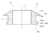
- a holding portion having a different shape from the holding portion 3 of the above-described embodiment is attached to the end of the main body 2 on the side to be inserted into the hand main body 110 (FIG. (Lower end).
- the holding portion 3BA on the side inserted into the hand main body 110 has a flange 32BA (an example of a third flange) extending toward the outside of the main body 2.
- the flange portion 32BA is formed at the edge of the through-hole 5 in parallel with a surface orthogonal to the height direction of the main body 2, and is formed vertically from the outer end of the surface 35BA toward the main body 2.
- Surface 33BA, and a surface (seating surface) 34BA formed at a portion of the flange portion 32BA in contact with the main body 2 and formed in parallel with a surface orthogonal to the height direction of the main body 2.
- the pad 1A can be attached in a state in which the pad 1A is securely adhered to the robot hand 100 by sandwiching the hand main body 110 between the flanges 32A and 32BA at both ends of the main body 2. Therefore, it is possible to prevent the pad 1A from falling off from the robot hand 100.
- the shape of the main body 2 is cylindrical, but is not limited to this.
- the main body 2 is appropriately selected according to the shape of the opening 101, and may be, for example, a prism such as a quadrangular prism or a polygonal prism.
- the shape of the holding portion 3 (3A, 3B) is a truncated cone, but the shape is not limited to this.
- the holding unit 3 is also appropriately selected according to the shape of the opening 101, and may be, for example, a truncated pyramid.
- the ring portion 31 (31A, 31B) has a substantially flat shape orthogonal to the axial direction of the main body 2, but is not limited thereto.
- the annular portion 31 (31A, 31B) has, for example, an inclined surface that is gradually inclined toward the inner side (as it approaches the through hole 5) toward the flange portion 32 (32A, 32B) or an outer surface (the through hole 5). May be formed as an inclined surface that is gradually inclined toward the flange portion 32 (32A, 32B) side (as the distance from the flange portion increases).
- the outer peripheral edge of the ring 31 (31A, 31B) is in contact with the wafer
- the inner peripheral edge of the ring 31 (31A, 31B) is in contact with the wafer.
- the tapered portions 33 are formed so that the ridge shape in a front view is straight, but the present invention is not limited to this.
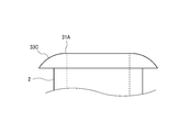
- the ridgeline shape in a front view may be an upwardly convex arched tapered portion 33C (see FIG. 8) or a downwardly concave arched tapered portion 33D (see FIG. 9).
- the tapered portion may not be continuous, and may be a tapered portion 33 ⁇ / b> E (see FIG. 10) having a stepped ridge shape in a front view.
- the present invention is not limited to the above-described embodiment, and may be appropriately modified and improved.
- the material, shape, dimension, numerical value, form, number, arrangement location, and the like of each component in the above-described embodiment are arbitrary and are not limited as long as the present invention can be achieved.
Landscapes
- Engineering & Computer Science (AREA)
- Robotics (AREA)
- Mechanical Engineering (AREA)
- Container, Conveyance, Adherence, Positioning, Of Wafer (AREA)
- Manipulator (AREA)
Abstract
基板を移載するロボットアームに取り付けられ、基板を保持するロボットハンド(100)は、ハンド本体部(110)と、該ハンド本体部(110)に設けられた開口部(101)に取り付けられ、基板を保持するパッド部材(1)と、を備えている。パッド部材(1)は、ロボットハンド(100)の開口部(101)に取り付けられ、その中央部に貫通孔(5)を有するパッド本体部(2)と、パッド部材(1)の先端側に設けられ、基板に当接される第1の環部(31A)と、第1の環部(31A)およびパッド本体部(2)と一体に設けられ、パッド本体部(2)の外側に向かって延設される第1の鍔部(32A)と、を備えている。
Description
本発明は、基板を保持するパッド部材を備えたロボットハンドに関する。
従来から、半導体製造の分野においては、ウエハを保持して搬送する搬送ロボットが用いられている。この搬送ロボットは、アームの先端に連結されたハンドを有している。ハンドは、その上面でウエハの裏面を保持し、ウエハを収納するカセット等との間においてウエハの受け渡しを行う。
これらの搬送ロボットのハンドは、ウエハを保持するための保持部を有している。保持部は、ハンドを構成している部材を直接削り出して形成するものや、天然ゴムや合成ゴム等の弾性材料により成形されたパッドをハンドに装着するものもある。
これらの搬送ロボットのハンドは、ウエハを保持するための保持部を有している。保持部は、ハンドを構成している部材を直接削り出して形成するものや、天然ゴムや合成ゴム等の弾性材料により成形されたパッドをハンドに装着するものもある。
このようなロボットアームのハンドにおいてパッドが用いられる例として、特許文献1は、ロボットのアーム先端に開口を通じて接続される取付部と、取付部に続く根本部と、根本部から一体的に連設されたスカート部とを備えた吸着用パッドを開示している。根本部は、略円形の断面を有し、その外周が徐々に拡径してスカート部に続いている。スカート部は、根本部より大きい略円形断面を呈し、スカート部の始点から終点に至る裾部は、スカート部の始点から終点にかけて徐々に薄くなって一体的に形成されている。スカート部の内部底面でワークと接する面の略中心部には、スカート部底面から開口まで達する貫通孔が設けられている。
特許文献2は、基板搬送装置の搬送アームに形成された第1の取付孔に取り付けられ、搬送アームの真空吸引路に連結されて、基板を搬送アームに真空吸着する真空吸着パッドを開示している。
しかしながら、上記のパッドを使用したロボットハンドによりウエハを保持して搬送する場合には次のような問題がある。
特許文献1の吸着用パッドは、スカート部の裾部を厚くすることによりワークとの接触部分を少なくするものである。ところが、近年において、吸着用パッドとワークとの接触面積はますます小さくなる傾向にあり、その対応が求められている。
特許文献2の真空吸着パッドは、搬送アームの取付孔にシール部材を介して取り付けられており、シール部材により気密性を確保している。そのため、真空吸着パッドの交換時にシール部材も交換する必要があり、真空吸着パッドの交換作業が煩雑となる。
本発明は、上記の点に鑑みてなされたものであり、ロボットハンドにウエハを載せて保持する場合、安定した保持を可能とし、また、パッド部材の取付けや取外しなどの交換作業を容易にすることができるロボットハンドを提供する。
上記目的を達成するために、本発明のロボットハンドは、
基板を移載するロボットアームに取り付けられ、前記基板を保持するロボットハンドであって、
ハンド本体部と、
該ハンド本体部に設けられた開口部に取り付けられ、前記基板を保持するパッド部材と、を備え、
前記パッド部材は、
前記開口部に取り付けられ、その中央部に貫通孔を有するパッド本体部と、
前記パッド部材の先端側に設けられ、前記基板に当接される第1の環部と、
前記第1の環部および前記パッド本体部と一体に設けられ、前記パッド本体部の外側に向かって延設される第1の鍔部と、を備えていることを特徴とする。
基板を移載するロボットアームに取り付けられ、前記基板を保持するロボットハンドであって、
ハンド本体部と、
該ハンド本体部に設けられた開口部に取り付けられ、前記基板を保持するパッド部材と、を備え、
前記パッド部材は、
前記開口部に取り付けられ、その中央部に貫通孔を有するパッド本体部と、
前記パッド部材の先端側に設けられ、前記基板に当接される第1の環部と、
前記第1の環部および前記パッド本体部と一体に設けられ、前記パッド本体部の外側に向かって延設される第1の鍔部と、を備えていることを特徴とする。
この構成によれば、パッドを押しつぶすように変形させながらパッド取付孔であるハンド本体部の開口部に差し込むことができるため、開口部へのパッドの取付けおよび取外し作業が容易になる。
また、本発明のロボットハンドにおいて、
前記パッド部材は、
前記パッド部材の後端側に設けられ、前記第1の環部と同形状で形成された第2の環部と、
前記第2の環部および前記パッド本体部と一体に設けられ、前記ハンド本体部に着座される第2の鍔部と、をさらに備えていてもよい。
前記パッド部材は、
前記パッド部材の後端側に設けられ、前記第1の環部と同形状で形成された第2の環部と、
前記第2の環部および前記パッド本体部と一体に設けられ、前記ハンド本体部に着座される第2の鍔部と、をさらに備えていてもよい。
この構成によれば、第1の環部と第2の環部とが対称構造であるため、第1の環部と第2の環部のどちらを基板と接触する側としてもよい。さらに、ロボットハンドにパッドを取り付ける際の誤設置を防止することができ、パッドの取付容易性を高めることができる。
また、本発明のロボットハンドにおいて、
前記パッド部材は、
前記パッド部材の後端側に前記パッド本体部と一体に設けられ、前記パッド本体部の外側に向かって延設される第3の鍔部をさらに備えていてもよい。
前記パッド部材は、
前記パッド部材の後端側に前記パッド本体部と一体に設けられ、前記パッド本体部の外側に向かって延設される第3の鍔部をさらに備えていてもよい。
この構成によれば、第3の鍔部を備えることで、パッドをロボットハンドの開口部へ容易に取り付けることができる。
また、本発明のロボットハンドにおいて、
前記ハンド本体部は、その内部に、一端部が前記開口部と連通され、他端部が吸排気ユニットに接続される通路部を有していてもよい。
前記ハンド本体部は、その内部に、一端部が前記開口部と連通され、他端部が吸排気ユニットに接続される通路部を有していてもよい。
この構成によれば、吸着なしでサイクルタイムが不足する場合などには、吸排気ユニットを別に設けて真空吸引路を介して真空引きを行うことにより、確実に基板を保持したまま移載することが可能となる。
また、本発明のロボットハンドにおいて、
前記パッド本体部は、円筒部材であり、
前記第1の鍔部は、前記第1の環部側から前記パッド本体部側に向かって拡径するテーパ部を有していてもよい。
前記パッド本体部は、円筒部材であり、
前記第1の鍔部は、前記第1の環部側から前記パッド本体部側に向かって拡径するテーパ部を有していてもよい。
また、本発明のロボットハンドにおいて、
前記第2の鍔部は、前記第2の環部側から前記パッド本体部側に向かって拡径するテーパ部を有していてもよい。
前記第2の鍔部は、前記第2の環部側から前記パッド本体部側に向かって拡径するテーパ部を有していてもよい。
これらの構成によれば、パッドをロボットハンドの開口部へ容易に取り付けることができる。
また、本発明のロボットハンドにおいて、
前記パッド部材は、前記ハンド本体部を前記第1の鍔部および前記第2の鍔部で挟持させることで、前記ハンド本体部に取り付けられてもよい。
前記パッド部材は、前記ハンド本体部を前記第1の鍔部および前記第2の鍔部で挟持させることで、前記ハンド本体部に取り付けられてもよい。
この構成によれば、ロボットハンドからのパッドの脱落を防止することができる。
また、本発明のロボットハンドにおいて、
前記パッド部材は、前記ハンド本体部を前記第1の鍔部および前記第3の鍔部で挟持させることで、前記ハンド本体部に取り付けられてもよい。
前記パッド部材は、前記ハンド本体部を前記第1の鍔部および前記第3の鍔部で挟持させることで、前記ハンド本体部に取り付けられてもよい。
この構成によれば、ロボットハンドからのパッドの脱落を防止することができる。
また、本発明のロボットハンドにおいて、
前記パッド部材は、樹脂組成物に導電性粒子を分散させてなる導電性樹脂で構成されていてもよい。
前記パッド部材は、樹脂組成物に導電性粒子を分散させてなる導電性樹脂で構成されていてもよい。
この構成によれば、基板の帯電、ひいては基板のスパークを防止することができるとともに、基板へのパーティクル付着を抑制することができる。
また、本発明のロボットハンドにおいて、
前記第1の環部の外径が、前記パッド本体部の外径よりも小さくなるように形成されていてもよい。
前記第1の環部の外径が、前記パッド本体部の外径よりも小さくなるように形成されていてもよい。
この構成によれば、基板とパッドの接触面(第1の環部)との接触面積を小さくすることができるため、基板へパッドが接触することに起因する基板へのパーティクルの付着を抑制することができる。
本発明によれば、ロボットハンドにウエハを載せて保持する場合、安定した保持を可能とし、また、パッド部材の取付けや取外しなどの交換作業を容易にすることができるロボットハンドを提供することができる。
以下、本発明の実施形態に係るロボットハンドおよびパッド部材について、図面を参照しつつ説明する。
先ず、図1から図4を参照して、実施形態に係るパッド1(パッド部材の一例)について説明する。パッド1は、例えば、半導体素子を製造するための材料であるウエハ(基板の一例)を保持する部品として用いられる。パッド1は、産業用ロボット、例えば、ウエハを設備間で受け渡すためのウエハ搬送ロボットのアーム(ロボットアームの一例)の先端に連結されたハンド(以下、ロボットハンドと称す)に取り付けられて使用され得る。ロボットハンドの詳細は後述する。
先ず、図1から図4を参照して、実施形態に係るパッド1(パッド部材の一例)について説明する。パッド1は、例えば、半導体素子を製造するための材料であるウエハ(基板の一例)を保持する部品として用いられる。パッド1は、産業用ロボット、例えば、ウエハを設備間で受け渡すためのウエハ搬送ロボットのアーム(ロボットアームの一例)の先端に連結されたハンド(以下、ロボットハンドと称す)に取り付けられて使用され得る。ロボットハンドの詳細は後述する。
図1から図4に示すように、パッド1は、中央部に設けられる本体部(パッド本体部)2と、本体部2の高さ方向(図2中では上下方向)における両端部に設けられる保持部3と、を備えている。本実施形態における保持部3は、本体部2の一方の端部(例えば、図2,4において上端部)に設けられる第1保持部3Aと、第1保持部3Aとは反対側の端部(例えば、図2,4において下端部)に設けられる第2保持部3Bとを含んでいる。本体部2と保持部3A,3Bとは、一体的に形成されている。
本体部2は、円筒部材である。本体部2の高さは、例えば、後述する開口部101(図6参照)におけるハンド本体部110の厚み(図6中では上下方向高さ)と略同一となるように設定されている。本体部2の高さは、例えば、1~2mm程度である。また、本体部2の外径R1は、後述する開口部101(図6参照)の内径と同径または同径よりもやや大きく形成される。好ましくは、本体部2の外径R1は、開口部101の内径と同径よりもやや大きく形成される。これによって、後述するパッド1の取り付けの際に、開口部101への本体部2の密着度が高まる。
本体部2の中央部および保持部3(3A,3B)の中央部には、本体部2と保持部3(3A,3B)とを連通するように貫通孔5が形成されている。本実施形態における貫通孔5は、断面円形で、パッド1の高さ方向に一様な径を有している。
保持部3(3A,3B)は、対象部材であるウエハ等を保持(載置)する際に当該ウエハ等に当接する環部31(31A,31B)を有している。環部31(31A,31B)は、貫通孔5の縁部において環状に形成されている。環部31Aと環部31Bとは、略同形状であってよい。本実施形態では、環部31Aと環部31Bとは、同径の円環形状に形成されている。環部31(31A,31B)の外径R2は、本体部2の外径R1よりも小さくなるように形成されている。言い換えると、環部31(31A,31B)の外径R2は、貫通孔5の径R4(図4参照)よりも若干大きく形成される。環部31(31A,31B)は、本体部2の高さ方向に直交するように略平坦面となるように形成されている。ウエハは、第1保持部3Aの環部31A(第1の環部の一例)または第2保持部3Bの環部31B(第2の環部の一例)のいずれか一方に接触した状態で保持される。
保持部3(3A,3B)は、その環部31(31A,31B)と本体部2との間に、本体部2および環部31(31A,31B)と一体に設けられた鍔部32(32A,32B)を有している。鍔部32(32A,32B)は、テーパ部33(33A,33B)と、着座面34(34A,34B)とから構成されている。テーパ部33(33A,33B)は、環部31(31A,31B)側から本体部2側に向かって拡径するように形成されている。着座面34(34A,34B)は、鍔部32(32A,32B)における本体部2と接する部分に形成され、本体部2の高さ方向に直交する面と平行に形成されている。すなわち、鍔部32(32A,32B)の外径R3は、本体部2の外径R1よりも大きくなるように形成されている。着座面34(34A,34B)は、パッド1がロボットハンド100に取り付けられたときに、ロボットハンド100の一部分に当接する面である。
このように、保持部3(3A,3B)は、截頭円錐形に形成されている。本体部2の上端部に設けられている第1保持部3Aは、環部31Aに向かうにしたがって径が小さくなるように形成されている。また、本体部2の下端部に設けられている第2保持部3Bは、環部31Bに向かうにしたがって径が小さくなるように形成されている。第1保持部3Aと第2保持部3Bとは、それらの間に本体部2を挟んで対称構造となるように形成されている。なお、図示は省略するが、パッド1の底面図は、図3に示す平面図と同様になる。また、パッド1の背面図、および左右側面図は、図2に示す正面図と同様になる。
環部31(31A,31B)の面積は、例えば、0.1~1平方ミリメートル(mm2)以下となるように形成される。環部31(31A,31B)の面積が0.1mm2未満であると、ウエハとの接触不良を生じる可能性がある。一方、環部31(31A,31B)の面積が1mm2よりも大きいと、ウエハへのパーティクル付着が問題となる可能性がある。例えば、貫通孔5の径R4が4mmに形成されている場合、環部31(31A,31B)の径方向幅Wは、0.01mm~0.065mmとなるように形成されている。また、環部31(31A,31B)の面積は、ロボットハンド100に取り付けられる全てのパッド1とウエハとの許容可能な接触総面積S、すなわち、パッド1の数によって変わる。全てのパッド1とウエハとの許容可能な接触総面積Sを一定とした場合、パッド1の数が1個,2個,3個,…と増えるに応じて、1個当たりの環部31(31A,31B)の面積は、S、S/2,S/3,…と小さくなる。言い換えると、全てのパッド1とウエハとの許容可能な接触総面積Sが決定され、かつ、ロボットハンド100に取り付けられる全てのパッド1の数が決定されたとき、環部31(31A,31B)の面積が一義的に定まる。
具体的には、例えば、接触総面積Sが3mm2以下、パッド1の総数が3個、貫通孔5の径R4が4mm、環部31(31A,31B)の外径R2が4.13mmのとき、環部31(31A,31B)の径方向幅Wは、0.065mmになる。このとき、環部31(31A,31B)の面積は0.83mm2、環部31の総面積は2.49mm2となり、接触総面積S(3mm2以下)を満足する。また、例えば、接触総面積Sが0.5mm2以下、パッド1の総数が3個、貫通孔5の径R4が4mm、環部31(31A,31B)の外径R2が4.02mmのとき、環部31(31A,31B)の径方向幅Wは、0.01mmになる。このとき、環部31(31A,31B)の面積は0.13mm2、環部31の総面積は0.39mm2となり、接触総面積S(0.5mm2以下)を満足する。
パッド1を構成する本体部2および保持部3(3A,3B)は、樹脂組成物に導電性粒子を分散させてなる導電性樹脂で構成されている。本体部2および保持部3(3A,3B)は、例えば、ポリテトラフルオロエチレン、パーフルオロアルコシキアルカン、エチレンテトラフルオロエチレンコポリマー等のフッ素樹脂等により作製することができる。樹脂組成物としては、その他、半導体ウエハをハンドリングするロボットハンドのパッドに慣用的に用いられている樹脂が全て適用可能である。
次に、図5および図6を参照して、パッド1を備えたロボットハンド100について説明する。
図5は、パッド1を備えたロボットハンド100を示す斜視図である。図6は、ロボットハンド100のVI-VI断面図である。
図5は、パッド1を備えたロボットハンド100を示す斜視図である。図6は、ロボットハンド100のVI-VI断面図である。
図5に示すように、ロボットハンド100には、その先端部にウエハを保持するためのパッド1が複数(本実施形態では3個)取り付けられている。また、ロボットハンド100は、図示を省略する吸排気ユニットを備えており、各パッド1は吸排気ユニットに後述の通路部102を介して接続される。ロボットハンド100に取り付けられたパッド1は、ウエハを真空吸着することにより、ロボットハンド100に対してウエハ等が位置ずれを起こしたり、ロボットハンド100から落下したりしないようにウエハ等を保持する。ロボットハンド100は、例えばアルミナなどのセラミック材料で構成されている。
図6に示すように、ロボットハンド100は、ハンド本体部110と、パッド1を取り付けるための開口部101と、開口部101と連通する通路部102(吸排気ユニットの一部)とを有している。
開口部101は、ハンド本体部110においてウエハ等が保持される側の面である保持面103(図6における上面)に形成される孔であり、通路部102に連通される。本実施形態における開口部101は、断面円形で、開口部101におけるハンド本体部110の厚み方向に一様な径を有している。開口部101の径は、本体部2の外径R1と略同一または外径R1よりもやや小さくとなるように形成されている。
開口部101は、ハンド本体部110においてウエハ等が保持される側の面である保持面103(図6における上面)に形成される孔であり、通路部102に連通される。本実施形態における開口部101は、断面円形で、開口部101におけるハンド本体部110の厚み方向に一様な径を有している。開口部101の径は、本体部2の外径R1と略同一または外径R1よりもやや小さくとなるように形成されている。
通路部102は、ハンド本体部110における保持面103の反対側の面(裏面)104に形成された溝を蓋部材(シール部材)105で密封してなる。通路部102の端部(図6中では右端部)は、図示を省略する吸排気ユニットに接続されている。
パッド1のいずれか一方の保持部3(3Aまたは3B)を、ハンド本体部110の保持面103側から開口部101内に弾性変形させながら挿入させる。このとき、鍔部32(32A,32B)はテーパ部33(33A,33B)を備えているため、保持部3(3Aまたは3B)は自動調心されながら開口部101内に導かれる。そして、鍔部32(32A,32B)の最大径部分321(図6参照)が、本体部2側に折り返されつつ弾性変形し、開口部101を完全に通過した後は元の形状に弾性変形することで、保持部3(3Aまたは3B)が開口部の101の下縁に密着する。例えば、第2保持部3Bを開口部101に挿入させる場合、第2保持部3Bの鍔部32B(テーパ部33B)が開口部101に入り込み、第2保持部3B(環部31Bおよび鍔部32B)が通路部102内に配置される。これにより、通路部102内に配置された第2保持部3Bの着座面34Bが通路部102の内壁面(図6において通路部102の上面)に当接(着座)する。
このとき、パッド1の本体部2は、開口部101の内周面に当接され、双方が密着する。また、第1保持部3Aは、開口部101内には差し込まれず、開口部101の外部(図6において保持面103よりも上側)に配置され、第1保持部3Aの着座面34Aが保持面103に当接した状態で取り付けられる。すなわち、ハンド本体部110を第1保持部3Aの鍔部32Aおよび第2保持部3Bの鍔部32Bで挟持することで、パッド1がハンド本体部110に確実に密着した状態で取り付けられる。このように、ロボットハンド100に取り付けられたパッド1は、第1保持部3Aの鍔部32Aと第2保持部3Bの鍔部32Bとによって取付位置が適正の位置に規定される。
パッド1が開口部101を介してロボットハンド100に取り付けられると、パッド1の貫通孔5とロボットハンド100の通路部102とが連通される。この状態で、吸排気ユニットの動作により貫通孔5内および通路部102内の空気を真空引きすることで、ロボットハンド100に載置されるウエハはパッド1の環部31A上に真空吸着される。
なお、本実施形態においては、1つのロボットハンド100には3個のパッド1が取り付けられている。そのため、ロボットハンド100におけるパッド1(環部31A)とウエハとの接触面積は、3mm2以下になる。
以上説明したように、本実施形態に係るロボットハンド100は、ハンド本体部110と、ハンド本体部110に設けられた開口部101に取り付けられ、ウエハを保持するパッド1と、を備えている。パッド1は、開口部101に取り付けられ、その中央部に貫通孔5を有する本体部2(パッド本体部の一例)と、パッド1の両端に設けられた環部31と、環部31および本体部2と一体に設けられ、本体部2の外側に向かって延設される鍔部32と、を備えている。そして、環部31の外径R2が、本体部2の外径R1よりも小さくなるように形成されている。この構成によれば、ウエハとパッド1の環部31との接触面積を小さくすることができるため、ウエハとパッド1とが接触することに起因するウエハへのパーティクルの付着を抑制することができる。また、この構成によれば、パッド取付孔であるハンド本体部110の開口部101に、パッド1を押しつぶすように変形させながら差し込むだけで、ロボットハンド100にパッド1を取り付けることができる。このため、開口部101へのパッド1の取付けおよび取外しの際に特別な器具や部材は不要である。よって、取り付け・取り外し作業が容易であるとともに、取り付け・取り外しに伴う部材コストはゼロである。さらに、パッド1は導電性粒子を含む樹脂組成物で構成されるため、パッド1をウエハに接触させることで、ウエハに帯電している静電気がアースされる。その結果、パッド1とウエハとの間でスパークが生じるおそれはない。ひいては、ウエハの破損のおそれがなくなり、ウエハの歩留まりが向上する。
また、本実施形態のロボットハンド100において、環部31は、パッド1の先端側に設けられた環部31A(第1の環部の一例)と、パッド1の後端側に設けられて環部31Aと同形状で形成された環部31B(第2の環部の一例)とを含み、鍔部32は、環部31Aおよび本体部2と一体に設けられた鍔部32A(第1の鍔部の一例)と、環部31Bおよび本体部2と一体に設けられた鍔部32B(第2の鍔部の一例)とを含む。このように、環部31Aと環部31Bとが対称構造であるため、環部31Aと環部31Bのどちらをウエハと接触する側としてもよい。さらに、鍔部32Aと鍔部32Bも対称構造であるため、ロボットハンド100にパッド1を取り付ける際の誤設置を防止することができ、パッド1の取り付けが容易である。
また、本実施形態のロボットハンド100において、ハンド本体部110は、その内部に、一端部が開口部101と連通され、他端部が吸排気ユニットに接続される通路部102を有している。これにより、パッドに対してウエハを吸着せずに搬送しようとすると、ウエハ搬送のサイクルタイムが不足する場合や、吸着力が不足する場合などには、吸排気ユニットを別に設けて通路部102を介して真空引きを行うことにより、確実にウエハを保持した状態で移載することが可能となる。
また、本実施形態のロボットハンド100において、パッド1がハンド本体部110に取り付けられた際、ハンド本体部110が鍔部32Aおよび鍔部32Bで挟持され、ハンド本体部110にパッド1が確実に密着した状態で保持される。これにより、ロボットハンド100からのパッド1の脱落を防止することができる。
また、本実施形態に係るロボットハンド100によれば、使用によりパッド1が摩耗した際には、ロボットハンド100自体を交換する必要がなくパッド1のみを取り付け交換すればよい。また、その交換の際に特別な器具や部材等は必要とせず、手作業で簡単に取り外し・取り付けができる。さらに、パッド1は初回の取り付け時は表裏フリーであり、初めにパッド1を取り付けて表側を使用した後、一旦パッド1を取り外して反対の裏側(通路部102内に位置していた側)を再使用することができる。そのため、交換作業に係る所要時間を大幅に低減することができ、また、交換に要する部材コストはなく、その上さらに、1つのパッド1を2回使用することができる。
また、本実施形態に係るパッド1によれば、パッド1をロボットハンド100に取り付ける際に、例えば特許文献2に開示される真空吸着パッドのようなシール部材等の装着が不要であるため、パッド1の交換作業がさらに容易となる。
なお、上記実施形態においては、環部31と鍔部32とから構成される保持部3を本体部2の両端部に設ける構成としたが、これに限定されない。保持部3は、本体部2の少なくとも一方の端部に設けられている構成であってもよい。例えば、図7に示すパッド1Aのように、上記実施形態の保持部3とは異なる形状の保持部を、ハンド本体部110内に挿入される側の本体部2の端部(図7中の下端部)に設けてもよい。具体的には、パッド1Aにおいて、ハンド本体部110内に挿入される側の保持部3BAは、本体部2の外側に向かって延設される鍔部32BA(第3の鍔部の一例)を備えている。鍔部32BAは、貫通孔5の縁部において本体部2の高さ方向に直交する面と平行に形成された面35BAと、面35BAの外端部から本体部2側に向けて垂直に形成された面33BAと、鍔部32BAにおける本体部2と接する部分に形成されて本体部2の高さ方向に直交する面と平行に形成された面(着座面)34BAとから構成されている。この構成によっても、本体部2の両端の鍔部32A,32BAによりハンド本体部110を挟持することで、パッド1Aがロボットハンド100に確実に密着した状態で取り付け可能となる。このため、ロボットハンド100からのパッド1Aの脱落を防止することができる。
また、上記実施形態では、本体部2の形状を円柱形としたがこれに限定されない。本体部2は、開口部101の形状に応じて適宜選択され、例えば、四角柱、多角柱等の角柱形であってもよい。
また、上記実施形態では、保持部3(3A,3B)の形状を截頭円錐形としたがこれに限定されない。保持部3もまた、開口部101の形状に応じて適宜選択され、例えば、截頭角錐形等であってもよい。
また、上記実施形態では、環部31(31A,31B)を本体部2の軸方向に直交する略平坦な形状としたがこれに限定されない。環部31(31A,31B)は、例えば、内側ほど(貫通孔5に近づくにしたがって)鍔部32(32A,32B)側に向かって徐々に傾斜する傾斜面、または、外側ほど(貫通孔5から離れるにしたがって)鍔部32(32A,32B)側に向かって徐々に傾斜する傾斜面として形成されていてもよい。前者の場合、環部31(31A,31B)における外周側縁部がウエハと接触され、後者の場合、環部31(31A,31B)における内周側縁部がウエハと接触される。
また、上記実施形態では、テーパ部33(33A,33B)は、正面視の稜線形状が直線状となるように形成されているがこれに限定されない。例えば、正面視の稜線形状が上向き凸型のアーチ状のテーパ部33C(図8参照)、または、下向き凹型のアーチ状のテーパ部33D(図9参照)であってもよい。また、テーパ部は、連続的でなくてもよく、正面視の稜線形状が段差状のテーパ部33E(図10参照)であってもよい。
なお、本発明は、上述した実施形態に限定されず、適宜、変形、改良等が自在である。その他、上述した実施形態における各構成要素の材質、形状、寸法、数値、形態、数、配置場所等は、本発明を達成できるものであれば任意であり、限定されない。
本出願は、2018年6月28日出願の日本特許出願2018-122932号に基づくものであり、その内容はここに参照として取り込まれる。
Claims (10)
- 基板を移載するロボットアームに取り付けられ、前記基板を保持するロボットハンドであって、
ハンド本体部と、
該ハンド本体部に設けられた開口部に取り付けられ、前記基板を保持するパッド部材と、を備え、
前記パッド部材は、
前記開口部に取り付けられ、その中央部に貫通孔を有するパッド本体部と、
前記パッド部材の先端側に設けられ、前記基板に当接される第1の環部と、
前記第1の環部および前記パッド本体部と一体に設けられ、前記パッド本体部の外側に向かって延設される第1の鍔部と、を備えている、ロボットハンド。 - 前記パッド部材は、
前記パッド部材の後端側に設けられ、前記第1の環部と同形状で形成された第2の環部と、
前記第2の環部および前記パッド本体部と一体に設けられ、前記ハンド本体部に着座される第2の鍔部と、をさらに備えている、請求項1に記載のロボットハンド。 - 前記パッド部材は、
前記パッド部材の後端側に前記パッド本体部と一体に設けられ、前記パッド本体部の外側に向かって延設される第3の鍔部をさらに備えている、請求項1に記載のロボットハンド。 - 前記ハンド本体部は、その内部に、一端部が前記開口部と連通され、他端部が吸排気ユニットに接続される通路部を有している、請求項1から3のいずれか一項に記載のロボットハンド。
- 前記パッド本体部は、円筒部材であり、
前記第1の鍔部は、前記第1の環部側から前記パッド本体部側に向かって拡径するテーパ部を有している、請求項1から4のいずれか一項に記載のロボットハンド。 - 前記パッド本体部は、円筒部材であり、
前記第2の鍔部は、前記第2の環部側から前記パッド本体部側に向かって拡径するテーパ部を有している、請求項2に記載のロボットハンド。 - 前記パッド部材は、前記ハンド本体部を前記第1の鍔部および前記第2の鍔部で挟持させることで、前記ハンド本体部に取り付けられる、請求項2に記載のロボットハンド。
- 前記パッド部材は、前記ハンド本体部を前記第1の鍔部および前記第3の鍔部で挟持させることで、前記ハンド本体部に取り付けられる、請求項3に記載のロボットハンド。
- 前記パッド部材は、樹脂組成物に導電性粒子を分散させてなる導電性樹脂で構成されている、請求項1から8のいずれか一項に記載のロボットハンド。
- 前記第1の環部の外径が、前記パッド本体部の外径よりも小さくなるように形成されている、請求項1から9のいずれか一項に記載のロボットハンド。
Applications Claiming Priority (2)
| Application Number | Priority Date | Filing Date | Title |
|---|---|---|---|
| JP2018122932A JP2021153076A (ja) | 2018-06-28 | 2018-06-28 | パッド部材を備えたロボットハンド |
| JP2018-122932 | 2018-06-28 |
Publications (1)
| Publication Number | Publication Date |
|---|---|
| WO2020003979A1 true WO2020003979A1 (ja) | 2020-01-02 |
Family
ID=68986294
Family Applications (1)
| Application Number | Title | Priority Date | Filing Date |
|---|---|---|---|
| PCT/JP2019/022813 Ceased WO2020003979A1 (ja) | 2018-06-28 | 2019-06-07 | パッド部材を備えたロボットハンド |
Country Status (3)
| Country | Link |
|---|---|
| JP (1) | JP2021153076A (ja) |
| TW (1) | TW202000403A (ja) |
| WO (1) | WO2020003979A1 (ja) |
Cited By (1)
| Publication number | Priority date | Publication date | Assignee | Title |
|---|---|---|---|---|
| KR20220094020A (ko) * | 2020-12-28 | 2022-07-05 | 세메스 주식회사 | 반송 유닛 및 이를 가지는 기판 처리 장치 |
Citations (8)
| Publication number | Priority date | Publication date | Assignee | Title |
|---|---|---|---|---|
| JPS6094487U (ja) * | 1983-11-30 | 1985-06-27 | 東芝機械株式会社 | ウエハ吸着装置 |
| JPH08107136A (ja) * | 1994-10-03 | 1996-04-23 | Dainippon Screen Mfg Co Ltd | 基板搬送装置 |
| JPH08112793A (ja) * | 1994-10-13 | 1996-05-07 | Toshiba Corp | 吸着保持装置及び実装装置 |
| JPH10156778A (ja) * | 1996-12-04 | 1998-06-16 | Smc Corp | 吸着用パッド |
| JP2002066972A (ja) * | 2000-09-01 | 2002-03-05 | Koganei Corp | 吸着装置 |
| JP2004059229A (ja) * | 2002-07-29 | 2004-02-26 | Espec Corp | 薄層基板製造方法、薄層基板移載装置及び薄層基板移載用吸着パッド |
| JP2008282870A (ja) * | 2007-05-08 | 2008-11-20 | Mitsubishi Cable Ind Ltd | 搬送アーム用パッド |
| JP2014072262A (ja) * | 2012-09-28 | 2014-04-21 | Hitachi High-Technologies Corp | 真空処理装置及び搬送装置 |
-
2018
- 2018-06-28 JP JP2018122932A patent/JP2021153076A/ja active Pending
-
2019
- 2019-06-07 WO PCT/JP2019/022813 patent/WO2020003979A1/ja not_active Ceased
- 2019-06-18 TW TW108121018A patent/TW202000403A/zh unknown
Patent Citations (8)
| Publication number | Priority date | Publication date | Assignee | Title |
|---|---|---|---|---|
| JPS6094487U (ja) * | 1983-11-30 | 1985-06-27 | 東芝機械株式会社 | ウエハ吸着装置 |
| JPH08107136A (ja) * | 1994-10-03 | 1996-04-23 | Dainippon Screen Mfg Co Ltd | 基板搬送装置 |
| JPH08112793A (ja) * | 1994-10-13 | 1996-05-07 | Toshiba Corp | 吸着保持装置及び実装装置 |
| JPH10156778A (ja) * | 1996-12-04 | 1998-06-16 | Smc Corp | 吸着用パッド |
| JP2002066972A (ja) * | 2000-09-01 | 2002-03-05 | Koganei Corp | 吸着装置 |
| JP2004059229A (ja) * | 2002-07-29 | 2004-02-26 | Espec Corp | 薄層基板製造方法、薄層基板移載装置及び薄層基板移載用吸着パッド |
| JP2008282870A (ja) * | 2007-05-08 | 2008-11-20 | Mitsubishi Cable Ind Ltd | 搬送アーム用パッド |
| JP2014072262A (ja) * | 2012-09-28 | 2014-04-21 | Hitachi High-Technologies Corp | 真空処理装置及び搬送装置 |
Cited By (2)
| Publication number | Priority date | Publication date | Assignee | Title |
|---|---|---|---|---|
| KR20220094020A (ko) * | 2020-12-28 | 2022-07-05 | 세메스 주식회사 | 반송 유닛 및 이를 가지는 기판 처리 장치 |
| KR102701437B1 (ko) * | 2020-12-28 | 2024-09-03 | 세메스 주식회사 | 반송 유닛 및 이를 가지는 기판 처리 장치 |
Also Published As
| Publication number | Publication date |
|---|---|
| JP2021153076A (ja) | 2021-09-30 |
| TW202000403A (zh) | 2020-01-01 |
Similar Documents
| Publication | Publication Date | Title |
|---|---|---|
| US8172288B2 (en) | Gripper, in particular a Bernoulli gripper | |
| US7669903B2 (en) | Ultra low contact area end effector | |
| US20060181095A1 (en) | Ultra low contact area end effector | |
| US7661183B2 (en) | Blade changing tool | |
| EP1715514B1 (en) | Non-contact carrier device | |
| JP2020004846A (ja) | アライメント装置、半導体ウエハ処理装置、およびアライメント方法 | |
| US9061423B2 (en) | Wafer handling apparatus | |
| JP2018157221A (ja) | ウェーハ‐ハンドリング・エンドエフェクタ | |
| KR20190017953A (ko) | 시료 유지구 | |
| CN111564396B (zh) | 半导体加工设备的机械手校准方法及半导体设备 | |
| JP7536577B2 (ja) | 真空吸着チャック | |
| JPH07136885A (ja) | 真空チャック | |
| KR20250112150A (ko) | 웨이퍼 또는 웨이퍼 어셈블리를 이송하기 위한 엔드 이펙터 | |
| JP2021153076A (ja) | パッド部材を備えたロボットハンド | |
| JPS62221130A (ja) | 真空チヤツク装置 | |
| TW201740493A (zh) | 用於基板容器之緩衝保持器 | |
| WO2021257488A1 (en) | Robotic end effector equipped with replaceable wafer contact pads | |
| WO2020013013A1 (ja) | 搬送用ハンド | |
| JP4480296B2 (ja) | 電子部材用収納容器 | |
| JPH10156778A (ja) | 吸着用パッド | |
| JP2005011748A (ja) | ボタン型電池の製造装置 | |
| US20250065509A1 (en) | Robot blade and wafer breakage prevention system | |
| JP7297211B2 (ja) | 固定用冶具 | |
| TW201909325A (zh) | 非接觸式處置器及使用非接觸式處置器處置工件之方法 | |
| CN109023287A (zh) | 沉积环及卡盘组件 |
Legal Events
| Date | Code | Title | Description |
|---|---|---|---|
| 121 | Ep: the epo has been informed by wipo that ep was designated in this application |
Ref document number: 19824696 Country of ref document: EP Kind code of ref document: A1 |
|
| NENP | Non-entry into the national phase |
Ref country code: DE |
|
| 122 | Ep: pct application non-entry in european phase |
Ref document number: 19824696 Country of ref document: EP Kind code of ref document: A1 |
|
| NENP | Non-entry into the national phase |
Ref country code: JP |