WO2020003937A1 - 無線通信システム、第一無線装置、第二無線装置及び無線通信方法 - Google Patents
無線通信システム、第一無線装置、第二無線装置及び無線通信方法 Download PDFInfo
- Publication number
- WO2020003937A1 WO2020003937A1 PCT/JP2019/022332 JP2019022332W WO2020003937A1 WO 2020003937 A1 WO2020003937 A1 WO 2020003937A1 JP 2019022332 W JP2019022332 W JP 2019022332W WO 2020003937 A1 WO2020003937 A1 WO 2020003937A1
- Authority
- WO
- WIPO (PCT)
- Prior art keywords
- wireless device
- wireless
- signal
- response signal
- wireless communication
- Prior art date
- Legal status (The legal status is an assumption and is not a legal conclusion. Google has not performed a legal analysis and makes no representation as to the accuracy of the status listed.)
- Ceased
Links
Images


Classifications
-
- H—ELECTRICITY
- H04—ELECTRIC COMMUNICATION TECHNIQUE
- H04W—WIRELESS COMMUNICATION NETWORKS
- H04W52/00—Power management, e.g. Transmission Power Control [TPC] or power classes
- H04W52/02—Power saving arrangements
- H04W52/0209—Power saving arrangements in terminal devices
- H04W52/0225—Power saving arrangements in terminal devices using monitoring of external events, e.g. the presence of a signal
- H04W52/0229—Power saving arrangements in terminal devices using monitoring of external events, e.g. the presence of a signal where the received signal is a wanted signal
-
- H—ELECTRICITY
- H04—ELECTRIC COMMUNICATION TECHNIQUE
- H04W—WIRELESS COMMUNICATION NETWORKS
- H04W28/00—Network traffic management; Network resource management
- H04W28/02—Traffic management, e.g. flow control or congestion control
- H04W28/06—Optimizing the usage of the radio link, e.g. header compression, information sizing, discarding information
-
- H—ELECTRICITY
- H04—ELECTRIC COMMUNICATION TECHNIQUE
- H04W—WIRELESS COMMUNICATION NETWORKS
- H04W4/00—Services specially adapted for wireless communication networks; Facilities therefor
- H04W4/30—Services specially adapted for particular environments, situations or purposes
- H04W4/38—Services specially adapted for particular environments, situations or purposes for collecting sensor information
-
- H—ELECTRICITY
- H04—ELECTRIC COMMUNICATION TECHNIQUE
- H04W—WIRELESS COMMUNICATION NETWORKS
- H04W52/00—Power management, e.g. Transmission Power Control [TPC] or power classes
- H04W52/02—Power saving arrangements
-
- H—ELECTRICITY
- H04—ELECTRIC COMMUNICATION TECHNIQUE
- H04W—WIRELESS COMMUNICATION NETWORKS
- H04W52/00—Power management, e.g. Transmission Power Control [TPC] or power classes
- H04W52/02—Power saving arrangements
- H04W52/0209—Power saving arrangements in terminal devices
- H04W52/0212—Power saving arrangements in terminal devices managed by the network, e.g. network or access point is leader and terminal is follower
- H04W52/0216—Power saving arrangements in terminal devices managed by the network, e.g. network or access point is leader and terminal is follower using a pre-established activity schedule, e.g. traffic indication frame
-
- H—ELECTRICITY
- H04—ELECTRIC COMMUNICATION TECHNIQUE
- H04W—WIRELESS COMMUNICATION NETWORKS
- H04W74/00—Wireless channel access
- H04W74/04—Scheduled access
- H04W74/06—Scheduled access using polling
-
- H—ELECTRICITY
- H04—ELECTRIC COMMUNICATION TECHNIQUE
- H04W—WIRELESS COMMUNICATION NETWORKS
- H04W74/00—Wireless channel access
- H04W74/08—Non-scheduled access, e.g. ALOHA
-
- H—ELECTRICITY
- H04—ELECTRIC COMMUNICATION TECHNIQUE
- H04W—WIRELESS COMMUNICATION NETWORKS
- H04W76/00—Connection management
- H04W76/10—Connection setup
- H04W76/14—Direct-mode setup
-
- H—ELECTRICITY
- H04—ELECTRIC COMMUNICATION TECHNIQUE
- H04W—WIRELESS COMMUNICATION NETWORKS
- H04W76/00—Connection management
- H04W76/20—Manipulation of established connections
- H04W76/28—Discontinuous transmission [DTX]; Discontinuous reception [DRX]
-
- H—ELECTRICITY
- H04—ELECTRIC COMMUNICATION TECHNIQUE
- H04W—WIRELESS COMMUNICATION NETWORKS
- H04W84/00—Network topologies
- H04W84/18—Self-organising networks, e.g. ad-hoc networks or sensor networks
-
- Y—GENERAL TAGGING OF NEW TECHNOLOGICAL DEVELOPMENTS; GENERAL TAGGING OF CROSS-SECTIONAL TECHNOLOGIES SPANNING OVER SEVERAL SECTIONS OF THE IPC; TECHNICAL SUBJECTS COVERED BY FORMER USPC CROSS-REFERENCE ART COLLECTIONS [XRACs] AND DIGESTS
- Y02—TECHNOLOGIES OR APPLICATIONS FOR MITIGATION OR ADAPTATION AGAINST CLIMATE CHANGE
- Y02D—CLIMATE CHANGE MITIGATION TECHNOLOGIES IN INFORMATION AND COMMUNICATION TECHNOLOGIES [ICT], I.E. INFORMATION AND COMMUNICATION TECHNOLOGIES AIMING AT THE REDUCTION OF THEIR OWN ENERGY USE
- Y02D30/00—Reducing energy consumption in communication networks
- Y02D30/70—Reducing energy consumption in communication networks in wireless communication networks
Definitions
- the present invention relates to a technology for performing wireless communication by intermittent operation.
- IoT Internet of Things
- devices such as sensors having a wireless communication function are arranged in various places, and information collection is realized.
- Equipment is installed even in places where power is not secured for information gathering.
- Such devices are required to be driven by batteries for a long period of time on a yearly basis. Therefore, power-saving operation is required.
- FIG. 8 is a time chart showing an operation example of wireless communication performed between the first wireless device 80 and the second wireless device 90 shown in Non-Patent Document 1.
- a first wireless device 80 transmits data
- a second wireless device 90 receives data.
- the second wireless device 90 intermittently performs preamble detection at a predetermined period (preamble detection period), and waits for a preamble transmitted from the first wireless device 80.
- the first wireless device 80 transmits a preamble for a time longer than the preamble detection cycle of the second wireless device 90 immediately before data transmission. By transmitting such a preamble, the first wireless device 80 performs reliable data communication with the second wireless device 90 that operates intermittently.
- the preamble detection is a detection of a specific pattern, unlike the electric field strength measurement and the like. Therefore, there is a merit that detection can be performed with high accuracy even in an environment where noise exists or an environment where a signal is buried in noise. Due to such advantages, it is also possible to apply LPWA (Low Power Wide Area) to a power-saving wireless communication system which is often operated in a poor environment.
- LPWA Low Power Wide Area
- Non-Patent Document 1 it is necessary to transmit the preamble for a longer time than the preamble detection cycle. Due to these restrictions, it is difficult to increase the preamble detection cycle, and as a result, it is difficult to reduce power consumption.
- an object of the present invention is to provide a technology capable of further reducing power consumption in a wireless communication device that operates intermittently.
- One embodiment of the present invention is a wireless communication system in which a first wireless device and a second wireless device intermittently perform wireless communication, wherein the first wireless device has an activation signal for activating the second wireless device. Is repeatedly transmitted in the first cycle until a response signal is received from the second wireless device, and when the response signal is received, transmits data to the second wireless device, and the second wireless device Repeating the start signal detection processing in a second cycle longer than the first cycle, and receiving the start signal when a part of the start signal is detected in the detection processing; Is a wireless communication system that transmits a response signal to the first wireless device when the address is addressed to the own device, and thereafter receives the data from the first wireless device.
- One embodiment of the present invention is the above wireless communication system, wherein when the second cycle is Trx and two disjoint integers are M and N, the first wireless device includes Trx in the activation signal. A preamble having a length of 1 / N or more is added, and the first cycle is a value M / N times Trx.
- One embodiment of the present invention is the above wireless communication system, wherein the first wireless device waits for a response signal for a predetermined time after transmission of the activation signal.
- One embodiment of the present invention is the above wireless communication system, wherein the first wireless device waits for a response signal for a predetermined time after transmitting the activation signal a plurality of times.
- One aspect of the present invention is the above wireless communication system, wherein the second wireless device transmits the response signal, and the first wireless device waits for a response signal at a random timing within a predetermined time. To send.
- One aspect of the present invention is a first wireless device in a wireless communication system in which a first wireless device and a second wireless device intermittently perform wireless communication, wherein the activation signal for activating the second wireless device is A communication control unit that repeatedly transmits in a first cycle until a response signal is received from a second wireless device, and transmits data to the second wireless device when the response signal is received, Device.
- One embodiment of the present invention is a second wireless device in a wireless communication system in which a first wireless device and a second wireless device intermittently perform wireless communication, wherein the first wireless device activates the second wireless device Repeatedly transmitting a start signal for causing the second wireless device to receive a response signal from the second wireless device in a first cycle, and transmitting data to the second wireless device when the response signal is received,
- the detection process of the activation signal is repeatedly executed in a second period longer than the first period, and when a part of the activation signal is detected in the detection process, the activation signal is received, and the activation signal is automatically transmitted.
- the second wireless device includes a communication control unit that transmits a response signal to the first wireless device when the data is addressed to the device, and thereafter receives the data from the first wireless device.
- One embodiment of the present invention is a wireless communication method performed by a wireless communication system in which a first wireless device and a second wireless device intermittently perform wireless communication, wherein the first wireless device activates the second wireless device. Step of repeatedly transmitting an activation signal for causing the activation signal to be received from the second wireless device in a first cycle until a response signal is received, and wherein the second wireless device transmits the activation signal in a second period longer than the first period. Repeating the detection process, receiving the start signal when a part of the start signal is detected in the detection process, and transmitting the response signal when the start signal is addressed to the first device. Transmitting to the device, the first wireless device, if the response signal is received, transmitting data to the second wireless device, and the second wireless device, the second wireless device, the response signal After sending Receiving said data from the serial first wireless device is a wireless communication method having.
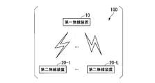
- FIG. 1 is a diagram illustrating a system configuration example of a wireless communication system.
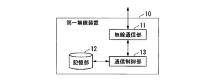
- FIG. 2 is a schematic block diagram illustrating a functional configuration of a first wireless device 10.
- FIG. 2 is a schematic block diagram illustrating a functional configuration of a second wireless device 20.
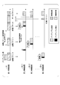
- FIG. 2 is a diagram illustrating a specific example of wireless communication performed between a first wireless device 10 and a second wireless device 20 according to the first embodiment.
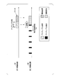
- 6 is a time chart in which only operations related to activation are extracted.
- FIG. 9 is a diagram illustrating a specific example of wireless communication performed between a first wireless device 10 and a plurality of second wireless devices 20 according to the second embodiment.
- FIG. 1 is a diagram illustrating a system configuration example of a wireless communication system.
- FIG. 2 is a schematic block diagram illustrating a functional configuration of a first wireless device 10.
- FIG. 2 is a schematic block diagram illustrating a functional configuration of a second wireless device 20.
- FIG. 2 is a diagram illustrating
- FIG. 13 is a diagram illustrating a specific example of wireless communication performed between a first wireless device 10 and a plurality of second wireless devices 20 according to a third embodiment.
- 9 is a time chart showing an operation example of wireless communication performed between a first wireless device 80 and a second wireless device 90 shown in Non-Patent Document 1.
- FIG. 1 is a diagram illustrating a system configuration example of a wireless communication system.
- the wireless communication system 100 includes a first wireless device 10 and a plurality of second wireless devices 20 (20-1 to 20-L).
- the first wireless device 10 and the second wireless device 20 perform wireless communication intermittently. Details of the operation of the wireless communication will be described later.
- FIG. 2 is a schematic block diagram showing a functional configuration of the first wireless device 10.
- the first wireless device 10 includes a wireless communication unit 11, a storage unit 12, and a communication control unit 13.
- the wireless communication unit 11, the storage unit 12, and the communication control unit 13 are connected by a bus.
- the wireless communication unit 11 performs wireless communication with the second wireless device 20 by transmitting and receiving radio waves by a predetermined wireless communication method.
- the wireless communication unit 11 is controlled by the communication control unit 13.
- the storage unit 12 is configured using a storage device such as a magnetic storage device or a semiconductor storage device.
- the storage unit 12 may store information indicating the operation of the first wireless device 10.
- the storage unit 12 may store information indicating an activation signal transmitted by the wireless communication unit 11.
- the information indicating the activation signal there is information indicating data included in the activation signal.
- the information indicating the activation signal there is information indicating a signal pattern of a preamble.
- the storage unit 12 may store activation timing information indicating the timing of transmitting the activation signal.
- the activation timing information there is information indicating a cycle when the activation signal is transmitted.
- the communication control unit 13 controls the operation of the wireless communication unit 11.
- the communication control unit 13 controls the wireless communication unit 11 to transmit an activation signal at a predetermined timing.
- the information indicating the signal pattern of the activation signal and the transmission timing of the activation signal may be stored in the storage unit 12 or may be defined in the communication control unit 13 in advance.
- the activation signal includes a preamble that is a signal of a predetermined pattern.
- the preamble is generated such that a predetermined pattern is continuously transmitted for a predetermined period (preamble length).
- the communication control unit 13 adds the generated preamble to the activation signal.
- All or a part of the function of the communication control unit 13 may be realized using hardware such as an ASIC (Application Specific Integrated Circuit), a PLD (Programmable Logic Device), and an FPGA (Field Programmable Gate Array).
- the communication control unit 13 is configured using a processor such as a CPU (Central Processing Unit).
- the communication control unit 13 may function by reading and executing a control program stored in the storage unit 12 by the processor.
- the control program may be recorded on a computer-readable recording medium.
- the computer-readable recording medium is, for example, a portable medium such as a flexible disk, a magneto-optical disk, a ROM, a CD-ROM, or a storage device such as a hard disk built in a computer system.
- the control program may be transmitted via a telecommunication line.
- FIG. 3 is a schematic block diagram showing a functional configuration of the second wireless device 20.
- the second wireless device 20 includes a wireless communication unit 21, a storage unit 22, and a communication control unit 23.
- the wireless communication unit 21, the storage unit 22, and the communication control unit 23 are connected by a bus.
- the wireless communication unit 21 performs wireless communication with the first wireless device 10 by transmitting and receiving radio waves in a predetermined wireless communication method.
- the wireless communication unit 21 is controlled by the communication control unit 23, and waits for reception of an activation signal at a predetermined timing (intermittent cycle).
- the storage unit 22 is configured using a storage device such as a magnetic storage device or a semiconductor storage device.
- the storage unit 22 stores information indicating the operation of the second wireless device 20.
- the storage unit 22 stores information indicating the length of an intermittent cycle in which the wireless communication unit 21 waits for reception of an activation signal.
- the communication control unit 23 controls the operation of the wireless communication unit 21.
- the communication control unit 23 waits for an activation signal at a predetermined timing.
- Information indicating the length of the intermittent period in which the communication control unit 23 waits for reception of the activation signal may be stored in the storage unit 22 or may be defined in the communication control unit 23 in advance.
- the communication control unit 23 transmits a response signal to the first wireless device 10.
- the communication control unit 23 may be realized using hardware such as an ASIC, a PLD, and an FPGA.
- the communication control unit 23 is configured using a processor such as a CPU.
- the communication control unit 23 may function by causing the processor to read and execute a control program stored in the storage unit 22.
- the control program may be recorded on a computer-readable recording medium.
- the computer-readable recording medium is, for example, a portable medium such as a flexible disk, a magneto-optical disk, a ROM, a CD-ROM, or a storage device such as a hard disk built in a computer system.
- the control program may be transmitted via a telecommunication line.
- FIG. 4 is a diagram illustrating a specific example of wireless communication performed between the first wireless device 10 and the second wireless device 20 according to the first embodiment.
- the first wireless device 10 activates the second wireless device 20 that operates intermittently, and then transmits data to the second wireless device 20.
- the flow of the wireless communication process according to the first embodiment will be described with reference to FIG. In the following description, each value is defined as follows.
- Lpr Preamble length (time)
- Lsl unit slot length (time)
- Tw_up transmission cycle of start signal (time: first cycle)
- Trx intermittent cycle (time: second cycle)
- M disjoint integers
- L the number of second wireless devices 20 j: offset
- a start packet is used as a specific example of a start signal
- a response packet is used as a specific example of a response signal. Is used.
- the communication control unit 13 of the first wireless device 10 generates a start packet to which a preamble of length Lpr is added.
- the length Lpr of the preamble is equal to or longer than the unit slot length Lsl.
- the length Lpr of the preamble is, for example, 1 / N times or more the length of Trx.
- the communication control unit 13 transmits the generated activation packet at a transmission cycle Tw_up of the activation signal.
- the length of Tw_up is M ⁇ Lsl. In other words, the length of Tw_up is M / N times the length of Trx.
- the communication control unit 13 waits for a response packet for a predetermined time thereafter.
- the response packet is a packet transmitted by the second wireless device 20 that has started upon receiving the start packet.
- the communication control unit 13 repeatedly transmits the activation packet according to the transmission cycle Tw_up of the activation signal.
- the information indicating the timing at which the first wireless device 10 waits for the response packet may be notified to the second wireless device 20 by including the information in the activation packet.
- Information indicating the timing at which the first wireless device 10 waits for a response packet may be stored or set in the second wireless device 20 in advance.
- the communication control unit 23 of the second wireless device 20 performs the preamble detection process at the intermittent cycle Trx.
- the length of Trx is N ⁇ Lsl.
- the communication control unit 23 of the second wireless device 20 determines whether the received activation packet is addressed to the own device. Also in the case where the activation packet has been broadcast-transmitted, the communication control unit 23 may determine that the activation packet is addressed to the own device. When the received activation packet is addressed to the own device, the communication control unit 23 transmits a response packet to the first wireless device 10.
- the communication control unit 13 of the first wireless device 10 transmits a data packet to the second wireless device 20.
- the communication control unit 13 may temporarily stop transmitting the activation packet after receiving the response packet.
- the information included in the activation packet is arbitrary except that a preamble is included. However, it is desirable that the activation packet include information indicating the destination. Based on the information indicating the destination, the communication control unit 23 of the second wireless device 20 may determine whether or not the activation packet is addressed to the own device.
- the length of Trx which is the intermittent period
- Lpr which is the time during which the preamble continues to be transmitted
- the first wireless device 10 repeatedly transmits an activation packet (activation signal) until a response packet is received.
- an activation packet activation signal
- the second wireless device 20 that operates intermittently can be started reliably and efficiently.
- FIG. 5 is a time chart in which only the operation related to activation is extracted.
- the operations related to the activation are, specifically, preamble transmission and preamble detection.
- the slot number of the slot including the timing at which the second wireless device 20 first performs the preamble detection is defined as “0”.
- the offset j represents the number of slots (offset) between the slot in which the first wireless device 10 has transmitted the preamble of the first activation packet and the slot number “0”. Therefore, the slot number of the slot in which the first wireless device 10 has transmitted the first activation packet preamble is defined as "-j".
- M and N are arbitrary prime integers, and the first wireless device 10 and the second wireless device 20 operate independently of each other. Therefore, j can take any value between 0 and M-1. In the following, it will be described that there is n that satisfies Expression (1) in arbitrary M, N, and j.
- transmission and preamble detection are performed using a start signal having a shorter preamble length at a cycle determined based on M and N having a relatively prime integer relationship.
- the number of transmissions of the activation packet is (1 + N) / 2 on average, and the total length of the transmitted preamble is Lsl ⁇ (1 + N) / 2. Therefore, when N is sufficiently large, it is approximately half of the intermittent reception cycle. In comparison with the conventional technique that always requires a preamble transmission longer than the intermittent reception cycle, it can be seen that the power required for transmitting the preamble can be reduced to approximately ⁇ ⁇ in the present embodiment.
- an erroneous start due to a start packet not addressed to the own device is a case where the second wireless device 20 that is the original destination is started earlier than the start.
- the probability is approximately 2.
- FIG. 6 is a diagram illustrating a specific example of wireless communication performed between the first wireless device 10 and the plurality of second wireless devices 20 according to the second embodiment.
- the first wireless device 10 activates at least one of the plurality of second wireless devices 20 (20-1 to 20-L) that operates intermittently, and any one of the second wireless devices 20 is activated.
- the data is transmitted to 20.
- the communication control unit 13 of the first wireless device 10 transmits a start packet to which a preamble having a length equal to or longer than Lsl is added in a cycle of M ⁇ Lsl. After transmitting the activation packet, the communication control unit 13 waits for a response packet for a predetermined time thereafter. When the response packet is not received while waiting for the response packet, the communication control unit 13 repeatedly transmits the activation packet according to the transmission cycle of the activation signal.
- the information indicating the timing at which the first wireless device 10 waits for the response packet may be notified to the second wireless device 20 by including the information in the activation packet. Information indicating the timing at which the first wireless device 10 waits for a response packet may be stored or set in the second wireless device 20 in advance.
- the communication control unit 23 of each second wireless device 20 intermittently executes the preamble detection process at the cycle of N ⁇ Lsl.
- the communication control unit 23 detects the preamble.
- the communication control unit 23 activates the second wireless device 20 and continues the reception processing until a predetermined timing.
- the predetermined timing may be, for example, a timing until the reception of the activation packet is completed, or may be a predetermined time.
- the communication control unit 23 of each second wireless device 20 determines whether the received start packet is addressed to the own device.
- the communication control unit 23 transmits a response packet to the first wireless device 10.
- the communication control unit 23 transmits the response packet at random timing within the standby time of the first wireless device 10.
- the communication control unit 23 may transmit the response packet with a random delay within the standby time of the first wireless device 10.
- the communication control unit 13 of the first wireless device 10 transmits a data packet to any one of the plurality of second wireless devices 20. At this time, the communication control unit 13 may temporarily stop transmitting the activation packet after receiving the response packet.
- the start packet is transmitted to the broadcast address, and the second wireless device 20-1 and the second wireless device 20-2 are activated by the second start packet transmission.
- Each of the second wireless device 20-1 and the second wireless device 20-2 transmits a response packet.
- the first wireless device 10 has transmitted the data packet to the second wireless device 20-1.
- the first wireless device 10 can more reliably transmit a data packet even in an environment where a plurality of second wireless devices 20 exist.
- the backoff value may be determined randomly. With this configuration, even if congestion should occur, it is possible to reduce the possibility that congestion will occur again in subsequent retransmission.
- FIG. 7 is a diagram illustrating a specific example of wireless communication performed between the first wireless device 10 and the plurality of second wireless devices 20 according to the third embodiment.
- the first wireless device 10 activates all of the plurality of second wireless devices 20 (20-1 to 20-L) that operate intermittently, and any one of them activates the second wireless device 20.
- the communication control unit 13 of the first wireless device 10 transmits a start packet to which a preamble having a length equal to or longer than Lsl is added N times in a cycle of M ⁇ Lsl. After transmitting the activation packet, the communication control unit 13 waits for a response packet for a predetermined time thereafter. When the response packet is not received while waiting for the response packet, the communication control unit 13 repeatedly transmits the activation packet according to the transmission cycle of the activation signal.
- the information indicating the timing at which the first wireless device 10 waits for the response packet may be notified to the second wireless device 20 by including the information in the activation packet. Information indicating the timing at which the first wireless device 10 waits for a response packet may be stored or set in the second wireless device 20 in advance.
- the communication control unit 23 of each second wireless device 20 intermittently executes the preamble detection process at the cycle of N ⁇ Lsl.
- the communication control unit 23 detects the preamble.
- the communication control unit 23 activates the second wireless device 20 and continues the reception processing until a predetermined timing.
- the predetermined timing may be, for example, a timing until the reception of the activation packet is completed, or may be a predetermined time.
- the communication control unit 23 of each second wireless device 20 determines whether the received start packet is addressed to the own device. If the received activation packet is addressed to the own device, the communication control unit 23 transmits a response packet at random timing within the standby time of the first wireless device 10. For example, the communication control unit 23 may transmit the response packet with a random delay within the standby time of the first wireless device 10.
- the communication control unit 13 of the first wireless device 10 that has received the response packet transmits the data packet to any one of the plurality of second wireless devices 20 (20-1 to 20-L).
- transmission and reception of the response packet are performed after the start packet has been transmitted N times. Therefore, all the communicable second wireless devices 20 can be activated. Thus, the wireless device 31 can transmit a data packet to an appropriate second wireless device 20 while grasping all the communicable second wireless devices 20.
- the present invention can be applied to a technology for performing wireless communication by intermittent operation.
Landscapes
- Engineering & Computer Science (AREA)
- Computer Networks & Wireless Communication (AREA)
- Signal Processing (AREA)
- Mobile Radio Communication Systems (AREA)
Abstract
間欠動作する無線通信装置において消費電力をより低下させること。 【解決手段】第一無線装置と第二無線装置とが間欠的に無線通信する無線通信システムであって、前記第一無線装置が、前記第二無線装置を起動させるための起動信号を前記第二無線装置から応答信号を受信するまで第一周期で繰り返し送信し、前記第二無線装置が、前記第一周期よりも長い第二周期で前記起動信号の検出処理を繰り返し実行し、前記検出処理において前記起動信号の一部が検出された場合には前記起動信号を受信し、前記起動信号が自装置宛てである場合には応答信号を前記第一無線装置に送信し、前記第一無線装置が、前記応答信号が受信された場合には前記第二無線装置に対してデータを送信し、前記第二無線装置が、前記応答信号を送信した後に前記第一無線装置から前記データを受信する。
Description
本発明は、間欠動作により無線通信を行う技術に関する。
IoT(Internet of Things)の進展に伴い、様々な場所に無線通信機能を有したセンサー等の機器が配置され、情報の収集が実現されている。電源が確保されない場所にも、情報収集のために機器は設置される。このような機器には、年単位での長期間にわたって電池での駆動が要求される。そのため、省電力での動作が必要となる。
従来から、間欠的に通信を行い、必要なとき以外は可能な限りスリープすることによって省電力が実現されている。特に、不定期に送信されるデータを待ち受ける必要のある場合には、送信データの有無を間欠的な動作で判定する省電力技術が必要となる。この省電力技術では、間欠的な判定動作の周期を長くし、かつ1回あたりの判定動作の時間を短くすることで、より高い省電力効果が得られる。
このような高い省電力効果を得るための技術として、非特許文献1に示されるようなプリアンブルサンプリングが提案されている。図8は、非特許文献1に示される第一無線装置80と第二無線装置90との間で行われる無線通信の動作例を示したタイムチャートである。図8において、第一無線装置80はデータを送信し、第二無線装置90はデータを受信する。この技術では、第二無線装置90は、所定の周期(プリアンブル検出周期)で間欠的にプリアンブル検出を行うことによって、第一無線装置80から送信されるプリアンブルを待ち受ける。第一無線装置80は、データ送信の直前に、第二無線装置90のプリアンブル検出周期よりも長い時間プリアンブルを送信する。このようなプリアンブルの送信によって、第一無線装置80は、間欠動作する第二無線装置90との間で確実なデータ通信を行う。
なお、プリアンブル検出は、電界強度測定などとは異なり、特定パターンの検出である。そのため、雑音が存在する環境や信号が雑音に埋もれるような環境においても精度良く検出できるというメリットがある。このようなメリットによって、劣悪な環境で運用されることが多いLPWA(Low Power Wide Area)の省電力無線通信システムへの適用も可能である。
Amre El-Hoiydi、"Aloha with Preamble Sampling for SporadicTraffic in Ad Hoc Wireless Sensor Networks"、 Proc. of IEEE ICC 2002、p.3418-3423
しかしながら、無線装置の実装上の制約や電波法規により、一般的に1回で送信できる無線パケットの長さには制限がある。非特許文献1に開示された技術では、プリアンブル検出周期よりも長い時間プリアンブルを送信する必要があった。これらの制約によって、プリアンブル検出周期を長くすることが困難となり、その結果消費電力を低下させることが困難となっていた。
上記事情に鑑み、本発明は、間欠動作する無線通信装置において消費電力をより低下させることが可能な技術を提供することを目的としている。
本発明の一態様は、第一無線装置と第二無線装置とが間欠的に無線通信する無線通信システムであって、前記第一無線装置は、前記第二無線装置を起動させるための起動信号を前記第二無線装置から応答信号を受信するまで第一周期で繰り返し送信し、前記応答信号が受信された場合には前記第二無線装置に対してデータを送信し、前記第二無線装置は、前記第一周期よりも長い第二周期で前記起動信号の検出処理を繰り返し実行し、前記検出処理において前記起動信号の一部が検出された場合には前記起動信号を受信し、前記起動信号が自装置宛てである場合には応答信号を前記第一無線装置に送信し、その後に前記第一無線装置から前記データを受信する、無線通信システムである。
本発明の一態様は、上記の無線通信システムであって、前記第二周期をTrx、互いに素な2つの整数をM及びNとおいた場合に、前記第一無線装置は、前記起動信号にTrxの1/N以上の長さのプリアンブルを付加し、前記第一周期はTrxのM/N倍の値である。
本発明の一態様は、上記の無線通信システムであって、前記第一無線装置は、前記起動信号の送信の後に所定の時間にわたって応答信号を待ち受ける。
本発明の一態様は、上記の無線通信システムであって、前記第一無線装置は、前記起動信号を複数回送信した後に所定の時間にわたって応答信号を待ち受ける。
本発明の一態様は、上記の無線通信システムであって、前記第二無線装置は、前記応答信号を送信する際に、前記第一無線装置が応答信号を待ち受ける所定の時間内でランダムなタイミングで送信する。
本発明の一態様は、第一無線装置と第二無線装置とが間欠的に無線通信する無線通信システムにおける第一無線装置であって、前記第二無線装置を起動させるための起動信号を前記第二無線装置から応答信号を受信するまで第一周期で繰り返し送信し、前記応答信号が受信された場合には前記第二無線装置に対してデータを送信する通信制御部、を備える第一無線装置である。
本発明の一態様は、第一無線装置と第二無線装置とが間欠的に無線通信する無線通信システムにおける第二無線装置であって、前記第一無線装置は、前記第二無線装置を起動させるための起動信号を前記第二無線装置から応答信号を受信するまで第一周期で繰り返し送信し、前記応答信号が受信された場合には前記第二無線装置に対してデータを送信し、前記第一周期よりも長い第二周期で前記起動信号の検出処理を繰り返し実行し、前記検出処理において前記起動信号の一部が検出された場合には前記起動信号を受信し、前記起動信号が自装置宛てである場合には応答信号を前記第一無線装置に送信し、その後に前記第一無線装置から前記データを受信する通信制御部、を備える第二無線装置である。
本発明の一態様は、第一無線装置と第二無線装置とが間欠的に無線通信する無線通信システムが行う無線通信方法であって、前記第一無線装置が、前記第二無線装置を起動させるための起動信号を前記第二無線装置から応答信号を受信するまで第一周期で繰り返し送信するステップと、前記第二無線装置が、前記第一周期よりも長い第二周期で前記起動信号の検出処理を繰り返し実行し、前記検出処理において前記起動信号の一部が検出された場合には前記起動信号を受信し、前記起動信号が自装置宛てである場合には応答信号を前記第一無線装置に送信するステップと、前記第一無線装置が、前記応答信号が受信された場合には前記第二無線装置に対してデータを送信するステップと、前記第二無線装置が、前記応答信号を送信した後に前記第一無線装置から前記データを受信するステップと、を有する無線通信方法である。
本発明により、間欠動作する無線通信装置において消費電力をより低下させることが可能となる。
以下、本発明の実施形態について説明する。
図1は、無線通信システムのシステム構成例を示す図である。無線通信システム100は、第一無線装置10と、複数台の第二無線装置20(20-1~20-L)と、を備える。第一無線装置10及び第二無線装置20は間欠的に無線通信を行う。無線通信の動作の詳細については後述する。
図1は、無線通信システムのシステム構成例を示す図である。無線通信システム100は、第一無線装置10と、複数台の第二無線装置20(20-1~20-L)と、を備える。第一無線装置10及び第二無線装置20は間欠的に無線通信を行う。無線通信の動作の詳細については後述する。
図2は、第一無線装置10の機能構成を示す概略ブロック図である。第一無線装置10は、無線通信部11、記憶部12及び通信制御部13を備える。無線通信部11、記憶部12及び通信制御部13はバスで接続される。
無線通信部11は、所定の無線通信方式で電波を送信及び受信することによって第二無線装置20との間で無線通信を行う。無線通信部11は、通信制御部13によって制御される。
記憶部12は、磁気記憶装置や半導体記憶装置等の記憶装置を用いて構成される。記憶部12は、第一無線装置10の動作を示す情報を記憶してもよい。例えば、記憶部12は、無線通信部11が送信する起動信号を示す情報を記憶してもよい。起動信号を示す情報の具体例として、起動信号に含まれるデータを示す情報がある。起動信号を示す情報のより具体的な例として、プリアンブルの信号パターンを示す情報がある。記憶部12は、起動信号を送信するタイミングを示す起動タイミング情報を記憶してもよい。起動タイミング情報の具体例として、起動信号が送信される際の周期を示す情報がある。
通信制御部13は、無線通信部11の動作を制御する。通信制御部13は、予め定められたタイミングで起動信号を送信するように無線通信部11を制御する。起動信号の信号パターンや起動信号の送信タイミングを示す情報は、記憶部12に記憶されてもよいし、予め通信制御部13において定義されてもよい。起動信号には、所定のパターンの信号であるプリアンブルが含まれる。プリアンブルは、所定のパターンが所定の期間(プリアンブル長)にわたって送信し続けられるように生成される。通信制御部13は、生成したプリアンブルを起動信号に付加する。
通信制御部13の機能の全て又は一部は、ASIC(Application Specific Integrated Circuit)やPLD(Programmable Logic Device)やFPGA(Field Programmable Gate Array)等のハードウェアを用いて実現されてもよい。通信制御部13は、CPU(Central Processing Unit)等のプロセッサを用いて構成される。通信制御部13は、プロセッサが記憶部12に記憶されている制御プログラムを読み出して実行することによって機能してもよい。制御プログラムは、コンピュータ読み取り可能な記録媒体に記録されてもよい。コンピュータ読み取り可能な記録媒体とは、例えばフレキシブルディスク、光磁気ディスク、ROM、CD-ROM等の可搬媒体、コンピュータシステムに内蔵されるハードディスク等の記憶装置である。制御プログラムは、電気通信回線を介して送信されてもよい。
図3は、第二無線装置20の機能構成を示す概略ブロック図である。第二無線装置20は、無線通信部21、記憶部22及び通信制御部23を備える。無線通信部21、記憶部22及び通信制御部23はバスで接続される。
無線通信部21は、所定の無線通信方式で電波を送信及び受信することによって第一無線装置10との間で無線通信を行う。無線通信部21は、通信制御部23によって制御されることによって、予め定められたタイミング(間欠周期)で起動信号の受信を待機する。
記憶部22は、磁気記憶装置や半導体記憶装置等の記憶装置を用いて構成される。記憶部22は、第二無線装置20の動作を示す情報を記憶する。例えば、記憶部22は、無線通信部21が起動信号の受信を待機する間欠周期の長さを示す情報を記憶する。
通信制御部23は、無線通信部21の動作を制御する。通信制御部23は、予め定められたタイミングで起動信号を待機する。通信制御部23が起動信号の受信を待機する間欠周期の長さを示す情報は、記憶部22に記憶されてもよいし、予め通信制御部23において定義されてもよい。通信制御部23は、起動信号が受信されると、応答信号を第一無線装置10に送信する。
通信制御部23の機能の全て又は一部は、ASICやPLDやFPGA等のハードウェアを用いて実現されてもよい。通信制御部23は、CPU等のプロセッサを用いて構成される。通信制御部23は、プロセッサが記憶部22に記憶されている制御プログラムを読み出して実行することによって機能してもよい。制御プログラムは、コンピュータ読み取り可能な記録媒体に記録されてもよい。コンピュータ読み取り可能な記録媒体とは、例えばフレキシブルディスク、光磁気ディスク、ROM、CD-ROM等の可搬媒体、コンピュータシステムに内蔵されるハードディスク等の記憶装置である。制御プログラムは、電気通信回線を介して送信されてもよい。
次に、無線通信システム100の動作の具体例について第1実施形態~第3実施形態の3つのパターンを説明する。
(第1実施形態)
図4は、第1実施形態における第一無線装置10と第二無線装置20との間で行われる無線通信の具体例を示す図である。第1実施形態では、第一無線装置10が、間欠動作する第二無線装置20を起動させ、その後に第二無線装置20に対してデータを送信する。
以下、図4を用いて第1実施形態における無線通信の処理の流れについて説明する。なお、以下の説明において、以下のように各値を定義する。
図4は、第1実施形態における第一無線装置10と第二無線装置20との間で行われる無線通信の具体例を示す図である。第1実施形態では、第一無線装置10が、間欠動作する第二無線装置20を起動させ、その後に第二無線装置20に対してデータを送信する。
以下、図4を用いて第1実施形態における無線通信の処理の流れについて説明する。なお、以下の説明において、以下のように各値を定義する。
・Lpr:プリアンブル長(時間)
・Lsl:単位スロット長(時間)
・Tw_up:起動信号の送信周期(時間:第一周期)
・Trx:間欠周期(時間:第二周期)
・M,N:互いに素な整数
・L:第二無線装置20の台数
・j:オフセット
また、以下の説明では、起動信号の具体例として起動パケットが用いられ、応答信号の具体例として応答パケットが用いられる。
・Lsl:単位スロット長(時間)
・Tw_up:起動信号の送信周期(時間:第一周期)
・Trx:間欠周期(時間:第二周期)
・M,N:互いに素な整数
・L:第二無線装置20の台数
・j:オフセット
また、以下の説明では、起動信号の具体例として起動パケットが用いられ、応答信号の具体例として応答パケットが用いられる。
まず、第一無線装置10の通信制御部13が、長さLprのプリアンブルが付加された起動パケットを生成する。プリアンブルの長さLprは、単位スロット長Lsl以上の長さである。プリアンブルの長さLprは、例えばTrxの1/N倍以上の長さである。通信制御部13は、生成された起動パケットを、起動信号の送信周期Tw_upで送信する。Tw_upの長さは、M×Lslである。言い換えれば、Tw_upの長さは、TrxのM/N倍の長さである。通信制御部13は、起動パケットを送信すると、その後に所定の時間にわたって応答パケットを待ち受ける。応答パケットは、起動パケットを受信して起動した第二無線装置20によって送信されるパケットである。通信制御部13は、応答パケットを待ち受けている間に応答パケットが受信されない場合は、起動信号の送信周期Tw_upにしたがって繰り返し起動パケットを送信する。なお、第一無線装置10が応答パケットを待ち受けるタイミングを示す情報は、その情報が起動パケットに含められることによって第二無線装置20に通知されてもよい。第一無線装置10が応答パケットを待ち受けるタイミングを示す情報は、予め第二無線装置20において記憶や設定がなされていてもよい。
第二無線装置20の通信制御部23は、間欠周期Trxでプリアンブル検出処理を実行する。Trxの長さは、N×Lslである。プリアンブル検出処理のタイミングでプリアンブルが第一無線装置10から送信されていると、通信制御部23はプリアンブルを検出する。プリアンブルが検出されると、通信制御部23は第二無線装置20を起動し、所定のタイミングまで受信処理を継続する。所定のタイミングは、例えば起動パケットの受信が完了するまでのタイミングであってもよいし、予め定められた時間の間であってもよい。
その後、第二無線装置20の通信制御部23は、受信された起動パケットが自装置宛であるか否かを判定する。起動パケットがブロードキャスト送信されたものであった場合も、通信制御部23は起動パケットが自装置宛てであると判定してもよい。受信された起動パケットが自装置宛てであった場合、通信制御部23は、第一無線装置10に対して応答パケットを送信する。
第一無線装置10の通信制御部13は、応答パケットを受信すると、第二無線装置20に対してデータパケットを送信する。このとき、通信制御部13は、応答パケットを受信した後に一時的に起動パケットの送信を中止してもよい。なお、起動パケットに含まれる情報は、プリアンブルが含まれること以外は任意である。ただし、起動パケットには、宛先を示す情報が含まれることが望ましい。この宛先を示す情報に基づいて、第二無線装置20の通信制御部23は起動パケットが自装置宛てであるか否か判定してもよい。
以上のように動作することによって、第1実施形態の無線通信システム100では、間欠周期であるTrxの長さを、プリアンブルが送信され続ける時間(プリアンブル長)であるLprよりも長くすることができる。そのため、より長い時間にわたって第二無線装置20のスリープ時間を確保することができる。したがって、間欠動作する無線通信装置において消費電力をより低下させることが可能となる。
上述したように、無線通信システム100では、第一無線装置10は、応答パケットが受信されるまで起動パケット(起動信号)を繰り返し送信する。このように動作することによって、間欠動作する第二無線装置20を確実かつ効率的に起動できる。以下、このような動作の原理について説明する。
図5は、起動に関する動作のみを抽出したタイムチャートである。起動に関する動作とは、具体的にはプリアンブル送信とプリアンブル検出である。なお、起動パケットに付加されるプリアンブルの長さLprは、Lsl以上の任意の長さを利用可能であるが、以下の説明では便宜的にLpr=Lslと定義し、時間を長さLslのスロット単位で区切る。第二無線装置20が最初にプリアンブル検出を行うタイミングが含まれるスロットのスロット番号を“0”と定義する。オフセットjは、第一無線装置10が1回目の起動パケットのプリアンブルを送信したスロットと、スロット番号“0”との間のスロット数(オフセット)を表す。そのため、第一無線装置10が1回目の起動パケットのプリアンブルを送信したスロットのスロット番号は“-j”と定義される。
第一無線装置10がプリアンブルを送信しているスロットと、第二無線装置20がプリアンブルを検出しているスロットとのタイミングが一致した場合に、第二無線装置20は起動する。そのため、以下の式を満たすn回目の起動パケットの送信で、第二無線装置20が起動する。

例えば、図5の例では、M=4、N=3、j=2である。そのため、3回目の起動パケットの送信で第二無線装置20が起動する。M及びNは互いに素な任意の整数であり、第一無線装置10と第二無線装置20とは互いに独立に動作している。そのため、jも0~M-1の間の任意の値を取り得る。以下では、任意のM、N、jにおいて、式(1)を満たすnが存在することを説明する。
完全剰余系の基本定理により、MとNとを互いに素な整数としたとき、{0,N,2N,3N,・・・,(M-1)×N}をMで割った余りは0~M-1の全て異なる値を取ることが知られている。また、剰余の性質より、同様に{-j,N-j,2N-j,3N-j,・・・,(M-1)×N-j}をMで割った余りも0~M-1の全て異なる値を取る。これは(n-1)×M-jに必ずNで割り切れる数が存在する事を意味し、式(1)を満たすN以下のnは必ず存在する。そのため、いかなる状況においても確実に起動することができる。
以上説明したように、本実施形態の無線通信システム100では、より短いプリアンブル長の起動信号を用いて、互いに素の整数の関係を有するM及びNに基づいて定められる周期で送信及びプリアンブル検出を行うことで、無線装置の実装上の制約や電波法規で制限される最長の送信時間よりも長い周期で間欠受信周期を設定することができる。このような設定において、第二無線装置20を確実かつ低消費電力の処理で起動させ、無線通信を行うことが可能となる。
また、以下に説明するように、同じ間欠受信周期で動作する従来技術と比較した場合、起動に要する消費電力の削減と、自装置宛ではない起動パケットで誤起動した場合の消費電力のペナルティの削減とが実現される。
まず、起動に要する消費電力の削減効果について説明する。本実施形態では、起動パケットの送信回数は平均で(1+N)/2回であり、送信されるプリアンブルの長さの合計はLsl×(1+N)/2となる。そのため、Nが十分に大きい場合は、概ね間欠受信周期の半分となる。常に間欠受信周期以上の長さのプリアンブル送信が必要であった従来技術と比較すると、本実施形態ではプリアンブルの送信に要する電力を概ね1/2に削減できることが分かる。
次に、誤起動時の消費電力のペナルティの削減効果について説明する。本実施形態では、自装置宛ではない起動パケットで誤起動してしまうのは、本来の宛先である第二無線装置20が起動するよりも早く起動してしまう場合である。その確率は、概ね1/2である。また、誤起動してしまった場合も、従来技術の1/Nである1回分のプリアンブルを受信するだけで済む。そのため、常に、誤起動の可能性があり、かつ、長いプリアンブル信号を全て受信する必要があった従来技術と比較すると、誤起動時の消費電力のペナルティを概ね1/2Nに低減できることが分かる。
(第2実施形態)
図6は、第2実施形態における第一無線装置10と複数の第二無線装置20との間で行われる無線通信の具体例を示す図である。第2実施形態では、第一無線装置10が、間欠動作する複数の第二無線装置20(20-1~20-L)の少なくとも1台を起動させ、その中のいずれかの第二無線装置20に対してデータを送信する。
図6は、第2実施形態における第一無線装置10と複数の第二無線装置20との間で行われる無線通信の具体例を示す図である。第2実施形態では、第一無線装置10が、間欠動作する複数の第二無線装置20(20-1~20-L)の少なくとも1台を起動させ、その中のいずれかの第二無線装置20に対してデータを送信する。
まず、第一無線装置10の通信制御部13は、Lsl以上の長さのプリアンブルを付加した起動パケットを、M×Lslの周期で送信する。通信制御部13は、起動パケットを送信すると、その後に所定の時間にわたって応答パケットを待ち受ける。通信制御部13は、応答パケットを待ち受けている間に応答パケットが受信されない場合は、起動信号の送信周期にしたがって繰り返し起動パケットを送信する。なお、第一無線装置10が応答パケットを待ち受けるタイミングを示す情報は、その情報が起動パケットに含められることによって第二無線装置20に通知されてもよい。第一無線装置10が応答パケットを待ち受けるタイミングを示す情報は、予め第二無線装置20において記憶や設定がなされていてもよい。
各第二無線装置20の通信制御部23は、それぞれN×Lslの周期で間欠的にプリアンブル検出処理を実行する。プリアンブル検出処理のタイミングでプリアンブルが第一無線装置10から送信されていると、通信制御部23はプリアンブルを検出する。プリアンブルが検出されると、通信制御部23は第二無線装置20を起動し、所定のタイミングまで受信処理を継続する。所定のタイミングは、例えば起動パケットの受信が完了するまでのタイミングであってもよいし、予め定められた時間の間であってもよい。
その後、各第二無線装置20の通信制御部23は、受信された起動パケットが自装置宛であるか否かを判定する。受信された起動パケットが自装置宛であった場合、通信制御部23は、第一無線装置10に対して応答パケットを送信する。このとき、通信制御部23は、第一無線装置10の待ち受け時間内でランダムなタイミングで応答パケットを送信する。例えば、通信制御部23は、第一無線装置10の待ち受け時間内で、ランダムに時間を遅延させて応答パケットを送信してもよい。
第一無線装置10の通信制御部13は、応答パケットを受信すると、複数の第二無線装置20のうちいずれかの装置に対してデータパケットを送信する。このとき、通信制御部13は、応答パケットを受信した後に一時的に起動パケットの送信を中止してもよい。
図6に示される具体例では、起動パケットがブロードキャストアドレスに対して送信され、2回目の起動パケット送信で第二無線装置20-1及び第二無線装置20-2が起動する。第二無線装置20-1及び第二無線装置20-2は、それぞれ応答パケットを送信する。その後、第一無線装置10は、第二無線装置20-1宛にデータパケットを送信している。
応答パケットの返信タイミングをランダムに決定させることで、複数の第二無線装置20が同一の起動パケットで起動してしまった場合においても応答パケットの輻輳を回避できる。これにより、第一無線装置10は、複数の第二無線装置20が存在する環境下でも、より確実にデータパケットを送信することが可能となる。
また、応答パケットの返送において輻輳(コリジョン)が生じた場合には、バックオフ値をランダムに決定するように構成されてもよい。このように構成されることによって、万が一輻輳が生じた場合であっても、その後の再送において再び輻輳が生じてしまう可能性を低減することが可能となる。
(第3実施形態)
図7は、第3実施形態における第一無線装置10と複数の第二無線装置20との間で行われる無線通信の具体例を示す図である。第3実施形態では、第一無線装置10が、間欠動作する複数の第二無線装置20(20-1~20-L)の全てを起動させ、その中のいずれかの第二無線装置20に対してデータを送信する。
図7は、第3実施形態における第一無線装置10と複数の第二無線装置20との間で行われる無線通信の具体例を示す図である。第3実施形態では、第一無線装置10が、間欠動作する複数の第二無線装置20(20-1~20-L)の全てを起動させ、その中のいずれかの第二無線装置20に対してデータを送信する。
まず、第一無線装置10の通信制御部13は、Lsl以上の長さのプリアンブルを付加した起動パケットを、M×Lslの周期でN回送信する。通信制御部13は、起動パケットを送信すると、その後に所定の時間にわたって応答パケットを待ち受ける。通信制御部13は、応答パケットを待ち受けている間に応答パケットが受信されない場合は、起動信号の送信周期にしたがって繰り返し起動パケットを送信する。なお、第一無線装置10が応答パケットを待ち受けるタイミングを示す情報は、その情報が起動パケットに含められることによって第二無線装置20に通知されてもよい。第一無線装置10が応答パケットを待ち受けるタイミングを示す情報は、予め第二無線装置20において記憶や設定がなされていてもよい。
各第二無線装置20の通信制御部23は、それぞれN×Lslの周期で間欠的にプリアンブル検出処理を実行する。プリアンブル検出処理のタイミングでプリアンブルが第一無線装置10から送信されていると、通信制御部23はプリアンブルを検出する。プリアンブルが検出されると、通信制御部23は第二無線装置20を起動し、所定のタイミングまで受信処理を継続する。所定のタイミングは、例えば起動パケットの受信が完了するまでのタイミングであってもよいし、予め定められた時間の間であってもよい。
その後、各第二無線装置20の通信制御部23は、受信された起動パケットが自装置宛であるか否かを判定する。受信された起動パケットが自装置宛であった場合、通信制御部23は、第一無線装置10の待ち受け時間内でランダムなタイミングで応答パケットを送信する。例えば、通信制御部23は、第一無線装置10の待ち受け時間内で、ランダムに時間を遅延させて応答パケットを送信してもよい。
応答パケットを受信した第一無線装置10の通信制御部13は、複数の第二無線装置20(20-1~20-L)のいずれかに対してデータパケットを送信する。
第3実施形態では、起動パケットがN回送信された後に応答パケットの送受信が実行される。そのため、通信可能な全ての第二無線装置20を起動することができる。これにより、無線装置31は通信可能な全ての第二無線装置20を把握しつつ、その中で適切な第二無線装置20に対してデータパケットを送信することができる。
以上、この発明の実施形態について図面を参照して詳述してきたが、具体的な構成はこの実施形態に限られるものではなく、この発明の要旨を逸脱しない範囲の設計等も含まれる。
本発明は、間欠動作により無線通信を行う技術に適用することができる。
10…第一無線装置, 20…第二無線装置, 11…無線通信部, 12…記憶部, 13…通信制御部, 21…無線通信部, 22…記憶部, 23…通信制御部
Claims (8)
- 第一無線装置と第二無線装置とが間欠的に無線通信する無線通信システムであって、
前記第一無線装置は、前記第二無線装置を起動させるための起動信号を前記第二無線装置から応答信号を受信するまで第一周期で繰り返し送信し、前記応答信号が受信された場合には前記第二無線装置に対してデータを送信し、
前記第二無線装置は、前記第一周期よりも長い第二周期で前記起動信号の検出処理を繰り返し実行し、前記検出処理において前記起動信号の一部が検出された場合には前記起動信号を受信し、前記起動信号が自装置宛てである場合には応答信号を前記第一無線装置に送信し、その後に前記第一無線装置から前記データを受信する、無線通信システム。 - 前記第二周期をTrx、互いに素な2つの整数をM及びNとおいた場合に、
前記第一無線装置は、前記起動信号にTrxの1/N以上の長さのプリアンブルを付加し、
前記第一周期はTrxのM/N倍の値である、請求項1に記載の無線通信システム。 - 前記第一無線装置は、前記起動信号の送信の後に所定の時間にわたって応答信号を待ち受ける、請求項1又は2に記載の無線通信システム。
- 前記第一無線装置は、前記起動信号を複数回送信した後に所定の時間にわたって応答信号を待ち受ける、請求項1又は2に記載の無線通信システム。
- 前記第二無線装置は、前記応答信号を送信する際に、前記第一無線装置が応答信号を待ち受ける所定の時間内でランダムなタイミングで送信する、請求項3又は4に記載の無線通信システム。
- 第一無線装置と第二無線装置とが間欠的に無線通信する無線通信システムにおける第一無線装置であって、
前記第二無線装置を起動させるための起動信号を前記第二無線装置から応答信号を受信するまで第一周期で繰り返し送信し、前記応答信号が受信された場合には前記第二無線装置に対してデータを送信する通信制御部、を備える第一無線装置。 - 第一無線装置と第二無線装置とが間欠的に無線通信する無線通信システムにおける第二無線装置であって、
前記第一無線装置は、前記第二無線装置を起動させるための起動信号を前記第二無線装置から応答信号を受信するまで第一周期で繰り返し送信し、前記応答信号が受信された場合には前記第二無線装置に対してデータを送信し、
前記第一周期よりも長い第二周期で前記起動信号の検出処理を繰り返し実行し、前記検出処理において前記起動信号の一部が検出された場合には前記起動信号を受信し、前記起動信号が自装置宛てである場合には応答信号を前記第一無線装置に送信し、その後に前記第一無線装置から前記データを受信する通信制御部、を備える第二無線装置。 - 第一無線装置と第二無線装置とが間欠的に無線通信する無線通信システムが行う無線通信方法であって、
前記第一無線装置が、前記第二無線装置を起動させるための起動信号を前記第二無線装置から応答信号を受信するまで第一周期で繰り返し送信するステップと、
前記第二無線装置が、前記第一周期よりも長い第二周期で前記起動信号の検出処理を繰り返し実行し、前記検出処理において前記起動信号の一部が検出された場合には前記起動信号を受信し、前記起動信号が自装置宛てである場合には応答信号を前記第一無線装置に送信するステップと、
前記第一無線装置が、前記応答信号が受信された場合には前記第二無線装置に対してデータを送信するステップと、
前記第二無線装置が、前記応答信号を送信した後に前記第一無線装置から前記データを受信するステップと、を有する無線通信方法。
Priority Applications (1)
| Application Number | Priority Date | Filing Date | Title |
|---|---|---|---|
| US17/254,999 US11553421B2 (en) | 2018-06-27 | 2019-06-05 | Wireless communication system, first wireless apparatus, second wireless apparatus and wireless communication method |
Applications Claiming Priority (2)
| Application Number | Priority Date | Filing Date | Title |
|---|---|---|---|
| JP2018-122325 | 2018-06-27 | ||
| JP2018122325A JP6542959B1 (ja) | 2018-06-27 | 2018-06-27 | 無線通信システム、第一無線装置、第二無線装置及び無線通信方法 |
Publications (1)
| Publication Number | Publication Date |
|---|---|
| WO2020003937A1 true WO2020003937A1 (ja) | 2020-01-02 |
Family
ID=67212146
Family Applications (1)
| Application Number | Title | Priority Date | Filing Date |
|---|---|---|---|
| PCT/JP2019/022332 Ceased WO2020003937A1 (ja) | 2018-06-27 | 2019-06-05 | 無線通信システム、第一無線装置、第二無線装置及び無線通信方法 |
Country Status (3)
| Country | Link |
|---|---|
| US (1) | US11553421B2 (ja) |
| JP (1) | JP6542959B1 (ja) |
| WO (1) | WO2020003937A1 (ja) |
Families Citing this family (3)
| Publication number | Priority date | Publication date | Assignee | Title |
|---|---|---|---|---|
| JP7436815B2 (ja) * | 2020-03-13 | 2024-02-22 | アイコム株式会社 | 無線機およびその受信方法 |
| US20230379821A1 (en) * | 2020-10-15 | 2023-11-23 | Nippon Telegraph And Telephone Corporation | Wireless communication system, wireless communication method and terminal device |
| JP7603532B2 (ja) * | 2021-06-07 | 2024-12-20 | 能美防災株式会社 | 無線通信システム |
Citations (2)
| Publication number | Priority date | Publication date | Assignee | Title |
|---|---|---|---|---|
| JP2009177243A (ja) * | 2008-01-21 | 2009-08-06 | Mitsubishi Electric Corp | 通信システムおよび通信装置 |
| JP2009219083A (ja) * | 2008-03-13 | 2009-09-24 | Mitsubishi Electric Corp | 無線基地局 |
Family Cites Families (9)
| Publication number | Priority date | Publication date | Assignee | Title |
|---|---|---|---|---|
| JP3051861B2 (ja) | 1992-12-28 | 2000-06-12 | 株式会社豊田中央研究所 | 移動体識別装置 |
| US7005985B1 (en) * | 1999-07-20 | 2006-02-28 | Axcess, Inc. | Radio frequency identification system and method |
| CN100481786C (zh) * | 2002-08-09 | 2009-04-22 | 爱信艾达株式会社 | 通信装置电源管理系统 |
| CA2705091A1 (en) * | 2007-11-25 | 2009-05-28 | Trilliant Networks, Inc. | System and method for power outage and restoration notification in an advanced metering infrasturcture network |
| JP2013005419A (ja) | 2011-06-22 | 2013-01-07 | Panasonic Corp | 通信システム、パケット送信装置及びプログラム |
| BR102014019159A2 (pt) * | 2013-08-06 | 2015-09-22 | Em Microelectronic Marin Sa | método para detecção contínua de presença de uma pessoa em transporte público |
| JP6126499B2 (ja) * | 2013-08-30 | 2017-05-10 | 株式会社東芝 | 電力変換装置、協調制御方法およびプログラム |
| KR102239090B1 (ko) * | 2014-06-05 | 2021-04-13 | 삼성전자 주식회사 | 위치 정보를 제공하기 위한 방법 및 장치 |
| JP6919262B2 (ja) * | 2017-03-27 | 2021-08-18 | カシオ計算機株式会社 | 通信装置、電子時計、通信方法、及びプログラム |
-
2018
- 2018-06-27 JP JP2018122325A patent/JP6542959B1/ja active Active
-
2019
- 2019-06-05 US US17/254,999 patent/US11553421B2/en active Active
- 2019-06-05 WO PCT/JP2019/022332 patent/WO2020003937A1/ja not_active Ceased
Patent Citations (2)
| Publication number | Priority date | Publication date | Assignee | Title |
|---|---|---|---|---|
| JP2009177243A (ja) * | 2008-01-21 | 2009-08-06 | Mitsubishi Electric Corp | 通信システムおよび通信装置 |
| JP2009219083A (ja) * | 2008-03-13 | 2009-09-24 | Mitsubishi Electric Corp | 無線基地局 |
Also Published As
| Publication number | Publication date |
|---|---|
| US20210266832A1 (en) | 2021-08-26 |
| JP6542959B1 (ja) | 2019-07-10 |
| JP2020005103A (ja) | 2020-01-09 |
| US11553421B2 (en) | 2023-01-10 |
Similar Documents
| Publication | Publication Date | Title |
|---|---|---|
| CN101803436B (zh) | 控制装置、终端装置及其方法、通信系统、集成电路 | |
| US9332376B2 (en) | Method and technical equipment for short range data transmission | |
| CN103828468B (zh) | 用于无线信道接入的无线装置和方法 | |
| JPWO2007086130A1 (ja) | タグ装置、トランシーバ装置およびタグシステム | |
| JP6542959B1 (ja) | 無線通信システム、第一無線装置、第二無線装置及び無線通信方法 | |
| JP2004236336A5 (ja) | ||
| CN115428506A (zh) | 测量配置方法、设备及存储介质 | |
| CN108513362B (zh) | 一种信道检测方法、装置及基站 | |
| CN110073696A (zh) | 唤醒无线电 | |
| CN111698739B (zh) | 通信装置和通信系统 | |
| JP5054119B2 (ja) | 無線センサネットワークにおいて、トーン及び/又はトーンパターンを利用してメッセージタイプを示すシステム、方法、及び装置 | |
| JP6711309B2 (ja) | 携帯端末位置検出装置、携帯端末位置検出方法 | |
| JP2007013577A (ja) | 通信装置及び通信方法及びプログラム | |
| JP6288268B2 (ja) | 無線通信デバイス、無線通信方法及びコンピュータプログラム | |
| JP4651440B2 (ja) | 無線通信端末、及びその送受信機能の管理方法 | |
| CN104137642A (zh) | 从无线接入点的信息传输 | |
| EP3051888B1 (en) | Transmission apparatus, reception apparatus, and communication system | |
| JP2004220262A (ja) | 位置情報通知装置 | |
| JP2010081128A (ja) | キャリアセンス方法及びキャリアセンス装置 | |
| CN108668239B (zh) | 低功耗并支持一对多交互的无线通信系统及其通信方法 | |
| CN114828218B (zh) | 参考信号传输时机有效性的确定方法和用户设备 | |
| JP4899765B2 (ja) | 車々間通信システムと、当該車々間通信システムに供する車両、車載装置及び中継器 | |
| CN114270939A (zh) | 直通链路同步信号的发送方法和装置 | |
| JP6743497B2 (ja) | 通信装置、通信方法、プログラム及び通信システム | |
| JP4563210B2 (ja) | 通信制御方法、通信ノード、及び通信システム |
Legal Events
| Date | Code | Title | Description |
|---|---|---|---|
| 121 | Ep: the epo has been informed by wipo that ep was designated in this application |
Ref document number: 19826685 Country of ref document: EP Kind code of ref document: A1 |
|
| NENP | Non-entry into the national phase |
Ref country code: DE |
|
| 122 | Ep: pct application non-entry in european phase |
Ref document number: 19826685 Country of ref document: EP Kind code of ref document: A1 |