WO2020003565A1 - コモンモードチョークコイル - Google Patents
コモンモードチョークコイル Download PDFInfo
- Publication number
- WO2020003565A1 WO2020003565A1 PCT/JP2019/001323 JP2019001323W WO2020003565A1 WO 2020003565 A1 WO2020003565 A1 WO 2020003565A1 JP 2019001323 W JP2019001323 W JP 2019001323W WO 2020003565 A1 WO2020003565 A1 WO 2020003565A1
- Authority
- WO
- WIPO (PCT)
- Prior art keywords
- coil
- common mode
- coils
- mode choke
- parallel running
- Prior art date
- Legal status (The legal status is an assumption and is not a legal conclusion. Google has not performed a legal analysis and makes no representation as to the accuracy of the status listed.)
- Ceased
Links
Images





Classifications
-
- H—ELECTRICITY
- H01—ELECTRIC ELEMENTS
- H01F—MAGNETS; INDUCTANCES; TRANSFORMERS; SELECTION OF MATERIALS FOR THEIR MAGNETIC PROPERTIES
- H01F17/00—Fixed inductances of the signal type
- H01F17/04—Fixed inductances of the signal type with magnetic core
- H01F17/06—Fixed inductances of the signal type with magnetic core with core substantially closed in itself, e.g. toroid
- H01F17/062—Toroidal core with turns of coil around it
-
- H—ELECTRICITY
- H01—ELECTRIC ELEMENTS
- H01F—MAGNETS; INDUCTANCES; TRANSFORMERS; SELECTION OF MATERIALS FOR THEIR MAGNETIC PROPERTIES
- H01F17/00—Fixed inductances of the signal type
- H01F17/04—Fixed inductances of the signal type with magnetic core
- H01F17/06—Fixed inductances of the signal type with magnetic core with core substantially closed in itself, e.g. toroid
-
- H—ELECTRICITY
- H01—ELECTRIC ELEMENTS
- H01F—MAGNETS; INDUCTANCES; TRANSFORMERS; SELECTION OF MATERIALS FOR THEIR MAGNETIC PROPERTIES
- H01F27/00—Details of transformers or inductances, in general
- H01F27/006—Details of transformers or inductances, in general with special arrangement or spacing of turns of the winding(s), e.g. to produce desired self-resonance
-
- H—ELECTRICITY
- H01—ELECTRIC ELEMENTS
- H01F—MAGNETS; INDUCTANCES; TRANSFORMERS; SELECTION OF MATERIALS FOR THEIR MAGNETIC PROPERTIES
- H01F27/00—Details of transformers or inductances, in general
- H01F27/08—Cooling; Ventilating
- H01F27/22—Cooling by heat conduction through solid or powdered fillings
-
- H—ELECTRICITY
- H01—ELECTRIC ELEMENTS
- H01F—MAGNETS; INDUCTANCES; TRANSFORMERS; SELECTION OF MATERIALS FOR THEIR MAGNETIC PROPERTIES
- H01F27/00—Details of transformers or inductances, in general
- H01F27/28—Coils; Windings; Conductive connections
- H01F27/30—Fastening or clamping coils, windings, or parts thereof together; Fastening or mounting coils or windings on core, casing, or other support
- H01F27/306—Fastening or mounting coils or windings on core, casing or other support
-
- H—ELECTRICITY
- H01—ELECTRIC ELEMENTS
- H01F—MAGNETS; INDUCTANCES; TRANSFORMERS; SELECTION OF MATERIALS FOR THEIR MAGNETIC PROPERTIES
- H01F17/00—Fixed inductances of the signal type
- H01F2017/0093—Common mode choke coil
Definitions
- the present invention relates to a common mode choke coil provided between a power supply and a load device to reduce noise generated on the load device side and transmitted to the power supply side.
- EMI noise Electro-Magnetic Interface Noise
- inverter of the power converter Since the EMI noise becomes conduction noise and flows through the power supply line and the ground, the EMI noise may be transmitted to other electric devices and cause a malfunction, for example.
- the common mode choke coil has a common mode inductance and is mainly used to reduce common mode noise.However, it also has a normal mode inductance due to leakage magnetic flux, that is, a leakage inductance, so it is also effective in reducing normal mode noise. There is.
- a common mode choke coil is composed of a magnetic core and a pair of coils, and has a split winding configuration in which each of the pair of coils is individually wound around the magnetic core.
- the magnetic core is magnetically saturated, and the common mode inductance decreases.
- Patent Document 1 a method of suppressing magnetic saturation by winding a pair of coils by bifilar has been proposed (for example, Patent Document 1). reference).
- the present invention has been made to solve the above-described problem, and has a small size capable of suppressing magnetic saturation without extending a winding portion in a magnetic path length direction and improving a performance of reducing normal mode noise. To obtain a common mode choke coil.
- a common mode choke coil includes a magnetic core and a pair of coils wound around a winding portion of the magnetic core.
- the pair of coils each include a first pole coil and a second pole coil spirally wound N turns around the winding section in the length direction of the winding section.
- the coil and the second pole coil are arranged in the winding portion such that one or more turns of the N turns are adjacent to each other, and the adjacent first pole coil and the second pole coil are In at least one turn, there are parallel running portions overlapping each other when viewed from the length direction of the winding portion, and non-parallel running portions separated from each other in a direction orthogonal to the length direction of the winding portion.
- N is an integer of 1 or more.
- the first pole coil and the second pole coil constituting the pair of coils are arranged in the winding portion such that one or more turns out of N turns are adjacent to each other.
- magnetic saturation can be suppressed without extending the winding portion in the magnetic path length direction.
- the first pole coil and the second pole coil run parallel to each other when viewed from the longitudinal direction of the winding part.
- a non-parallel running part separated from each other in a direction perpendicular to the length direction of the winding part.
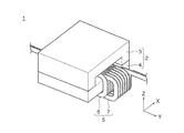
- FIG. 2 is a perspective view showing a common mode choke coil according to Embodiment 1 of the present invention.
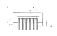
- FIG. 2 is a front view showing the common mode choke coil according to Embodiment 1 of the present invention.
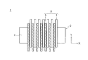
- FIG. 2 is a bottom view showing the common mode choke coil according to Embodiment 1 of the present invention.
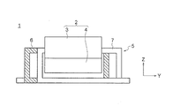
- FIG. 2 is a side view showing the common mode choke coil according to Embodiment 1 of the present invention.
- FIG. 3 is a side view showing a pair of coils in the common mode choke coil according to Embodiment 1 of the present invention.
- FIG. 2 is a schematic diagram illustrating a current flowing through a coil of the common mode choke coil according to Embodiment 1 of the present invention and a magnetic flux generated thereby.
- FIG. 9 is a schematic diagram showing a magnetic flux linked from an adjacent coil in the conventional common mode choke coil disclosed in Patent Document 1.
- FIG. 3 is a schematic diagram showing a magnetic flux linking from an adjacent coil in the common mode choke coil according to Embodiment 1 of the present invention.
- FIG. 9 is a front view showing a common mode choke coil according to Embodiment 2 of the present invention.
- FIG. 9 is a bottom view showing a common mode choke coil according to Embodiment 2 of the present invention.
- FIG. 9 is a side view showing a pair of coils in a common mode choke coil according to Embodiment 2 of the present invention.
- FIG. 10 is a side view showing a pair of coils and a metal housing in a common mode choke coil according to Embodiment 2 of the present invention. It is a side view showing a pair of coils and a metal case in a common mode choke coil of a comparative example.
- FIG. 10 is a side view showing a common mode choke coil according to Embodiment 3 of the present invention.
- FIG. 14 is a side view showing a common mode choke coil according to Embodiment 4 of the present invention.
- FIG. 15 is a front view showing a common mode choke coil according to Embodiment 5 of the present invention.
- FIG. 15 is a bottom view showing a common mode choke coil according to Embodiment 5 of the present invention.
- FIG. 16 is a perspective view showing a pair of coils in a common mode choke coil according to Embodiment 6 of the present invention.
- FIG. 14 is a side view showing a pair of coils in a common mode choke coil according to Embodiment 6 of the present invention.
- FIG. FIG. 1 is a perspective view showing a common mode choke coil according to Embodiment 1 for carrying out the present invention
- FIG. 2 is a front view showing a common mode choke coil according to Embodiment 1
- FIG. FIG. 4 is a side view showing the common mode choke coil according to the first embodiment
- FIG. 5 is a side view showing the common mode choke coil according to the first embodiment. It is a side view which shows a coil.
- a common mode choke coil 1 includes a magnetic core 2 including a U-shaped core 3 and an I-shaped core 4, a positive pole coil 6 as a first pole coil, and a negative pole as a second pole coil. And a pair of coils 5 including a coil 7.
- the X direction is the direction of the magnetic path length of the magnetic core 2.
- the direction of the magnetic path length of the magnetic core 2 is the direction of the magnetic flux passing through the I-shaped core 4 which is the winding part of the pair of coils 5, and is the length direction of the I-shaped core 4.
- the Z direction is a direction orthogonal to the X direction, and is a direction in which the U-shaped core 3 is connected to the I-shaped core 4.
- the Y direction is a direction orthogonal to the X direction and the Z direction.
- the U-shaped core 3 and the I-shaped core 4 are made of a magnetic material such as ferrite.
- the magnetic core 2 is arranged such that the I-shaped core 4 connects the both leg portions of the U-shaped core 3 to constitute a closed magnetic circuit.
- the positive electrode coil 6 and the negative electrode coil 7 are formed by spirally winding a rectangular copper conductor around the I-shaped core 4 for seven turns so that the turns are alternately arranged in the X direction.
- the positive coil 6 and the negative coil 7 have the same coil shape, and are wound around the I-shaped core 4 so as to be shifted in the Y direction in FIG. As a result, as shown in FIG.
- the positive coil 6 and the negative coil 7 have a parallel running portion 11 that is an overlapping region overlapping each other and a non-parallel running portion that is a non-overlapping region that does not overlap each other, as viewed in the X direction.
- the non-overlapping region where the positive electrode coil 6 and the negative electrode coil 7 do not overlap each other when viewed from the X direction is a region where the positive electrode coil 6 and the negative electrode coil 7 are separated from each other in a direction orthogonal to the X direction.
- the X direction can also be expressed as a coil axis direction of a pair of coils 5 wound in a spiral.
- the positive coil 6 and the negative coil 7 constituting the pair of coils 5 are spirally formed on the I-shaped core 4 so that the turn portions are alternately arranged in the X direction. It is wound up. That is, the pair of coils 5 is formed by bifilar winding. Therefore, the dimension of the common mode choke coil 1 in the X direction can be reduced as compared with the conventional common mode choke coil according to Patent Documents 2 and 3, in which a bifilar winding and a split winding are used to form a pair of coils. , Miniaturization is achieved.
- FIG. 6 is a schematic diagram showing a current flowing through the coil of the common mode choke coil according to the first embodiment and a magnetic flux generated thereby.
- I indicates a current
- ⁇ indicates a magnetic flux.
- the parallel running section 11 the current I flows in opposite directions and close to the positive electrode coil 6 and the negative electrode coil 7. As a result, the magnetic flux ⁇ generated by the current I flowing through the positive coil 6 and the negative coil 7 cancel each other out, thereby suppressing the magnetic saturation of the magnetic core 2.
- the parallel running portion 11 has a small contribution to the normal mode inductance.
- the non-parallel running section 12 the current I flows in the positive coil 6 and the negative coil 7 in opposite directions and apart. As a result, a part of the magnetic flux ⁇ generated when the current I flows through the positive electrode coil 6 and the negative electrode coil 7 remains without being canceled and contributes to the normal mode inductance. However, the non-parallel running portion 12 contributes little to the suppression of the magnetic saturation of the magnetic core 2.
- the pair of coils 5 includes the parallel running portion 11 that contributes to the suppression of the magnetic saturation of the magnetic core 2 and the non-parallel running portion 12 that contributes to the normal mode inductance.
- the common mode choke coil 1 can suppress the magnetic saturation of the magnetic core 2 and improve the performance of reducing the normal mode noise.
- FIG. 7 is a schematic diagram showing the shape of the one-turn coil 8.
- Equation 1 The partial self-inductance and partial mutual inductance of the 81 turn coil 8 are expressed by Equation 1.
- i and j each take one of the values 1, 2, 3, and 4, and correspond to the section numbers shown in FIG.
- ⁇ 0 is the magnetic permeability of vacuum
- 1 is the length of the coil 8
- the coil 8 of the i-th section and the coil of the j-th section when i ⁇ j 8 is the distance.
- the loop inductance of the one-turn coil 8 is expressed by Expression 2.
- FIG. 8 is a schematic diagram showing a magnetic flux linked from an adjacent coil in a conventional common mode choke coil disclosed in Patent Document 1
- FIG. 9 is an adjacent diagram in a common mode choke coil according to the first embodiment. It is the schematic diagram which showed the magnetic flux linked from a coil. Note that the positive electrode coils 60 and 70 in FIG. 8 have the same coil shape as the positive electrode coil 6 and the negative electrode coil 7.
- Equation 3 shows the relationship between the loop inductance of the coil and the magnetic flux linking the coil.
- ⁇ is a magnetic flux linking the coil
- B is a magnetic flux density linking the coil
- s is a surface surrounded by the coil
- I is a current flowing through the coil.
- the positive coil 60 and the negative coil 70 wound in bifilar winding only have an overlapping region where they overlap each other when viewed in the X direction. That is, in the conventional common mode choke coil, the positive electrode coil 60 and the negative electrode coil 70 have only the parallel running part 11 and do not have the non-parallel running part 12. Then, as shown in FIG. 8, the current I flowing between the adjacent positive coil 60 and the negative coil 70 is in the opposite direction, and the interlinking magnetic flux ⁇ is in the opposite direction. Thereby, the magnetic flux ⁇ linking the adjacent positive coil 60 and negative coil 70 is canceled each other.
- the value of L loop that is, the normal mode inductance, is (1-n) times.
- n is 0 ⁇ n ⁇ 1.
- the adjacent positive coil 6 and the negative electrode coil 7 include the parallel running part 11 and the non-parallel running part 12, the adjacent positive coil 6 and negative electrode coil 7 The facing area is reduced by the presence of the non-parallel running portions 12.
- the facing area between the adjacent positive coil 6 and the negative coil 7 becomes m times larger than the facing area of the adjacent positive coils 60 and 70 having only the parallel portion 11. I do.
- the ratio of the canceled magnetic flux ⁇ to the total magnetic flux ⁇ linked to the adjacent positive electrode coil 6 and negative electrode coil 7 is (n ⁇ m) times.
- m is 0 ⁇ m ⁇ 1.
- the facing area between the positive coil 6 and the negative coil 7 is such that the non-parallel running portion 12 is provided so that the facing area between the positive coils 60 and 70 in Patent Document 1 is 20 mm ⁇ 50 mm. , 20 mm ⁇ 45 mm.
- m 0.9.
- the magnetic flux density B is perpendicular to the surface surrounded by the positive electrode coil 6 and the negative electrode coil 7 and is constant regardless of the position.
- the pair of coils 5 includes the positive coil 6 spirally wound around the I-shaped core 4 of the magnetic core 2 so that the turns are alternately arranged in the X direction. And a negative electrode coil 7.
- Each of the positive coil 6 and the negative coil 7 includes a parallel running portion 11 that contributes to suppression of magnetic saturation and a non-parallel running portion 12 that contributes to normal mode inductance.
- the positive coil 6 and the negative coil 7 have the same coil shape. However, the positive coil 6 and the negative coil 7 may have different coil shapes. Further, in the first embodiment, the adjacent positive coil 6 and the negative coil 7 include the parallel running portion 11 and the non-parallel running portion 12 in all of the seven turns. The negative coil 7 only needs to include the parallel running part 11 and the non-parallel running part 12 in at least one of the seven turns.
- FIG. FIG. 10 is a front view showing a common mode choke coil according to Embodiment 2 for carrying out the present invention
- FIG. 11 is a bottom view showing a common mode choke coil according to Embodiment 2
- FIG. 13 is a side view showing a pair of coils in a common mode choke coil according to Embodiment 2
- FIG. 13 is a side view showing a pair of coils and a metal housing in the common mode choke coil according to Embodiment 2
- FIG. It is a side view showing a pair of coils and a metal case in a common mode choke coil of a comparative example.
- each of the pair of coils 21 includes a positive coil 22 as a first pole coil and a negative coil 23 as a second pole coil.
- the turn portion of the positive coil 22 is configured to be larger in the Z direction than the turn portion of the negative coil 23.
- the positive electrode coil 22 and the negative electrode coil 23 are wound around the I-shaped core 4 by seven turns so that the turns are alternately arranged in the X direction.
- a metal housing 25 as a metal member is arranged on the opposite side of the U-shaped core 3 of the I-shaped core 4 in the Z direction.
- the positive electrode coil 22 and the negative electrode coil 23 are arranged such that the outer peripheral portion of the I-shaped core 4 in the Z direction opposite to the U-shaped core 3 is in contact with the metal housing 25 via the flat insulator 24. Then, it is held by the metal housing 25. Therefore, the positive coil 22 protrudes from the negative coil 23 on the side opposite to the metal housing 25 in the Z direction.
- the positive coil 22 and the negative coil 23 have a parallel running portion 11 that is an overlapping region overlapping each other and a non-parallel running portion that is a non-overlapping region that does not overlap each other, as viewed in the X direction.
- a metal material such as copper, iron, and aluminum is used for the metal housing 25, a metal material such as copper, iron, and aluminum is used.
- the other configuration is the same as that of the first embodiment.
- the positive coil 22 and the negative coil 23 are spirally wound around the I-shaped core 4 of the magnetic core 2 so that the turns are alternately arranged in the X direction.
- Each of the positive coil 22 and the negative coil 23 includes a parallel running portion 11 that contributes to suppression of magnetic saturation and a non-parallel running portion 12 that contributes to normal mode inductance. Therefore, also in the second embodiment, the same effect as in the first embodiment can be obtained.
- the non-parallel running portions 12 of the pair of coils 21 ⁇ / b> A are arranged at positions near the metal housing 25. Therefore, since the leakage magnetic flux links to the metal housing 25, the leakage magnetic flux is shielded, and the contribution to the normal mode inductance is reduced.
- the non-parallel running portions 12 of the pair of coils 21 are arranged at positions away from the metal housing 25. Therefore, since the leakage magnetic flux does not interlink with the metal housing 25, the leakage magnetic flux is not shielded, and the contribution to the normal mode inductance is increased.
- the non-parallel running portions 12 of the pair of coils 21 are arranged at positions away from the metal housing 25. Therefore, since the leakage magnetic flux in the non-parallel running portion 12 does not interlink with the metal housing 25, the improvement of the normal mode inductance becomes more effective than the case where the leakage magnetic flux interlinks with the metal housing 25.
- the metal housing 25 is disposed on the opposite side of the I-shaped core 4 of the pair of coils 21 from the U-shaped core 3. It may be arranged on the U-shaped core 3 side of the shaped core 4 or on one side of the pair of coils 21 in the Y direction. Also in this case, the non-parallel running part 12 is arranged on the opposite side of the metal casing 25 of the I-shaped core 4.
- a dedicated metal housing 25 is used as a metal member for holding the pair of coils 21.
- the metal member is a housing of a device for mounting a common mode choke coil, a common mode choke.
- a heat sink for cooling the coil, a ground of a substrate on which the common mode choke coil is mounted, or the like may be used.
- the pair of coils is held by these metal members via the insulator.
- the non-parallel running portions 12 of the pair of coils 21 may be disposed on the opposite side to the metal member such as the casing of the I-shaped core, the heat sink, and the ground of the substrate.
- FIG. FIG. 15 is a side view showing a common mode choke coil according to Embodiment 3 for carrying out the present invention.
- an auxiliary magnetic material core 30 configured as a rectangular quadrangular prism is placed in a space surrounded by the positive coil 6 and the negative coil 7 of the non-parallel running portion 12 from one end in the X direction of the space. It is inserted to reach the end.
- the other configuration is the same as that of the first embodiment.
- the positive electrode coil 6 and the negative electrode coil 7 are spirally wound around the I-shaped core 4 of the magnetic core 2 so that the turns are alternately arranged in the X direction. ing.
- Each of the positive coil 6 and the negative coil 7 includes a parallel running portion 11 that contributes to suppression of magnetic saturation and a non-parallel running portion 12 that contributes to normal mode inductance. Therefore, also in the third embodiment, the same effect as in the first embodiment can be obtained.
- the auxiliary magnetic core 30 is disposed in a space surrounded by the positive coil 6 and the negative coil 7 of the non-parallel running section 12.
- the common mode choke coil 1B according to the third embodiment is different from the first embodiment in that the auxiliary magnetic core 30 is not disposed in the space surrounded by the positive coil 6 and the negative coil 7 of the non-parallel running portion 12.
- the normal mode inductance can be more effectively improved without increasing the volume.
- the auxiliary magnetic core 30 is arranged in a space surrounded by the positive coil 6 and the negative coil 7 of the non-parallel running part 12 in the common mode choke coil 1 according to the first embodiment.
- the same effect can be obtained by arranging the auxiliary magnetic core 30 in a space surrounded by the positive coil and the negative coil of the non-parallel running part in the common mode choke coil according to another embodiment.
- the auxiliary magnetic core 30 may be made of the same magnetic material as the magnetic core 2 or may be made of a different magnetic material.
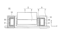
- FIG. 16 is a side view showing a common mode choke coil according to Embodiment 4 for implementing the present invention.
- a metal plate 31 which is a heat dissipating member having a rectangular quadrangular cylindrical structure, is placed in a space surrounded by the positive coil 6 and the negative coil 7 of the non-parallel running portion 12 in the X direction of the space. It is inserted from one end to the other end. Further, the metal plate 31 is inserted into the space in a state where the metal plate 31 is in contact with the inner peripheral wall surfaces of the positive coil 6 and the negative coil 7 constituting the space via the insulator 32.
- a metal material such as copper, iron, and aluminum is used for the metal plate 31.
- the other configuration is the same as that of the first embodiment.
- positive electrode coil 6 and negative electrode coil 7 are spirally wound around I-shaped core 4 of magnetic core 2 so that the turns are alternately arranged in the X direction. ing.
- Each of the positive coil 6 and the negative coil 7 includes a parallel running portion 11 that contributes to suppression of magnetic saturation and a non-parallel running portion 12 that contributes to normal mode inductance. Therefore, also in the fourth embodiment, the same effect as in the first embodiment can be obtained.
- the metal plate 31 is in contact with the positive coil 6 and the negative coil 7 via the insulator 32 in a space surrounded by the positive coil 6 and the negative coil 7 of the non-parallel running part 12.
- the common mode choke coil 1C according to the fourth embodiment is different from the first embodiment in which the metal plate 31 is not disposed in the space surrounded by the positive coil 6 and the negative coil 7 of the non-parallel running portion 12.
- the heat radiation of the pair of coils 5 can be improved without increasing the volume.
- the metal plate 31 does not shield the leakage magnetic flux generated from the non-parallel running parts 12, the effect of improving the normal mode inductance by providing the non-parallel running parts 12 is not hindered.
- the metal plate 31 is inserted into the space surrounded by the positive coil 6 and the negative coil 7 of the non-parallel running part 12 in the common mode choke coil 1 according to the first embodiment.
- the same effect can be obtained by inserting the metal plate 31 into a space surrounded by the positive coil and the negative coil of the non-parallel running part in the common mode choke coil according to another embodiment.
- the interior of the metal plate 31 is hollow.
- the metal plate 31 may be filled with a resin material, and the auxiliary magnetic core 30 according to the third embodiment may be placed in the metal plate 31. May be inserted.
- the positive electrode coil and the negative electrode coil are spirally wound around the I-shaped core by seven turns so that the turns are alternately arranged in the X direction.
- the negative coil is not limited to seven turns, and may be any number of turns.
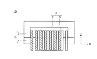
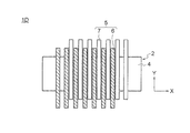
- FIG. 17 is a front view showing a common mode choke coil according to a fifth embodiment for carrying out the present invention
- FIG. 18 is a bottom view showing a common mode choke coil according to the fifth embodiment.
- the positive coil 6 and the negative coil 7 are formed by spirally winding a copper rectangular conductor around the I-shaped core 4 so that six turns of seven turns are alternately arranged in the X direction. Have been.
- the other configuration is the same as that of the first embodiment.
- the positive coil 6 and the negative coil 7 are spirally wound around the I-shaped core 4 of the magnetic core 2 so that the turns are alternately arranged in the X direction.
- Each of the positive coil 6 and the negative coil 7 includes a parallel running portion 11 that contributes to suppression of magnetic saturation and a non-parallel running portion 12 that contributes to normal mode inductance. Therefore, also in the fifth embodiment, the same effect as in the first embodiment can be obtained.
- the positive coil 6 and the negative coil 7 are arranged on the I-shaped core 4 so as to be shifted by one turn in the X direction. That is, since the positive coil 6 and the negative coil 7 are configured using both bifilar winding and split winding, it is possible to improve the performance of reducing normal mode noise while suppressing magnetic saturation.
- the positive coil 6 and the negative coil 7 are arranged so that, of the total of 7 turns, 6 turns are alternately arranged in the X direction, and the remaining 1 turn is arranged adjacent to its own coil.
- the positive electrode coil 6 and the negative electrode coil 7 are arranged so that, of the total of seven turns, six turns are adjacent to coils of different poles, and the remaining one turn is adjacent to coils of the same pole.
- the number of turns in which coils of different poles are adjacent to each other is not limited to six, and may be any number between six and one. Further, the number of turns of the positive coil 6 and the negative coil 7 is not limited to 7 turns.
- the positive electrode coil 6 and the negative electrode coil 7 are arranged such that M turns out of all N turns are adjacent to coils of different poles, and so that (N ⁇ M) turns are adjacent to coils of the same pole. It should be done.
- N is an integer of 2 or more
- M is an integer of 1 or more and (N-1) or less.
- the normal mode inductance can be adjusted only by the ratio of the number of turns N to M. As a result, the normal mode inductance can take only discrete values.
- the normal mode inductance can be adjusted to an arbitrary value.
- the positive coil 6 and the negative coil 7 in the common mode choke coil 1 according to the first embodiment are arranged so that six turns out of a total of seven turns are alternately arranged in the X direction and remain. Although one turn is arranged so as to be adjacent to the coil of the same pole, the positive and negative coils in the common mode choke coil according to another embodiment are alternately arranged in six turns out of seven turns in the X direction. The same effect can be obtained even if the coils are arranged side by side and the remaining one turn is arranged adjacent to the coil having the same pole.
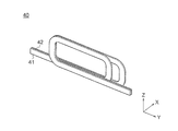
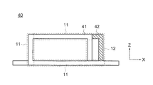
- FIG. 19 is a perspective view showing a pair of coils in a common mode choke coil according to Embodiment 6 for carrying out the present invention.
- FIG. 20 shows a pair of coils in a common mode choke coil according to Embodiment 6. It is a side view.
- the pair of coils 40 includes a positive coil 41, which is a one-turn first pole coil, and a negative coil 42, which is a one-turn second pole coil.
- the positive electrode coil 41 and the negative electrode coil 42 are wound around an I-shaped core which is a winding part of a magnetic core so as to be adjacent to each other.
- the positive electrode coil 41 and the negative electrode coil 42 include, when viewed from the X direction, a parallel running portion 11 that is an overlapping region that overlaps each other, and a non-parallel running portion 12 that is a non-overlapping region that does not overlap each other.
- the other configuration is the same as that of the first embodiment.
- the positive coil 41 and the negative coil 42 each having one turn are wound around the I-shaped magnetic core so as to be adjacent to each other in the X direction.
- the positive coil 41 and the negative coil 42 each include, in one turn, a parallel running portion 11 contributing to suppression of magnetic saturation and a non-parallel running portion 12 contributing to normal mode inductance. Therefore, also in the sixth embodiment, the same effect as in the first embodiment can be obtained.
- the effect of the present invention can be obtained even when the positive coil and the negative coil have one turn. Therefore, according to the present invention, the positive electrode coil and the negative electrode coil are spirally wound at least one turn in the longitudinal direction of the I-shaped core, and the positive electrode coil and the negative electrode coil are wound at least one turn at a time. And at least one turn between the adjacent positive and negative coils may be provided with a parallel running portion and a non-parallel running portion.
- the metal housing 25 may be arranged at a position away from the non-parallel running portions 12 of the pair of coils 40.
- the auxiliary magnetic core 30 may be inserted into a space surrounded by the positive coil 41 and the negative coil 42 of the non-parallel running portion 12.
- the metal plate 31 is provided between the positive coil 41 and the negative coil 42 via the insulator 32 in the space surrounded by the positive coil 41 and the negative coil 42 of the non-parallel part 12. May be arranged to be in contact with.
- the magnetic core composed of the U-shaped core and the I-shaped core is used.
- the magnetic core is limited to the core formed by combining the U-shaped core and the I-shaped core.
- a core combining a U-shaped core and a U-shaped core, a toroidal core, or the like may be used.
- the rectangular coil conductor made of copper is used as the material of the positive electrode coil and the negative electrode coil, but other highly conductive material, for example, a rectangular conductor made of aluminum may be used. Further, although a rectangular conductor is used as a material of the positive coil and the negative coil, a conductor having a circular cross section may be used.
- the positive electrode coil and the negative electrode coil are formed in a rectangular cylindrical coil shape, but the coil shape is not limited to the rectangular cylindrical shape.
Landscapes
- Engineering & Computer Science (AREA)
- Power Engineering (AREA)
- Microelectronics & Electronic Packaging (AREA)
- Coils Or Transformers For Communication (AREA)
- Coils Of Transformers For General Uses (AREA)
Abstract
この発明によるコモンモードチョークコイルは、磁性体コア2と、上記磁性体コアの巻線部4に巻かれた一対のコイル5と、を備え、上記一対のコイル5は、それぞれ、上記巻線部に上記巻線部の長さ方向に螺旋状にNターン巻かれた第1の極コイル6と第2の極コイル7とを備え、上記第1の極コイル6と第2の極コイル7とは、上記Nターンのうち、1ターン以上が隣り合うように上記巻線部4に配置されており、隣り合う上記第1の極コイルと上記第2の極コイルとの少なくとも1ターンにおいて、上記巻線部4の長さ方向から見て、互いに重なる並走部11と、上記巻線部4の長さ方向と直交する方向に互いに離れる非並走部12と、を備え、但し、Nは1以上の整数である。
Description
この発明は、電源と負荷装置との間に設けられて、負荷装置側で発生して電源側へ伝搬されるノイズを低減するコモンモードチョークコイルに関する。
負荷装置である交流駆動モータを制御する電力変換装置においては、電力変換装置のインバータの高速スイッチング動作により、EMIノイズ(Electo-Magnetic Interference Noise)が発生する。このEMIノイズが、伝導ノイズとなって、電源ラインおよびアースを流れるために、他の電気機器に伝わって誤動作を起こさせるなどの悪影響を及ぼす可能性がある。ノイズには、電源と負荷装置との間の伝送路を伝搬するノーマルモードノイズと、伝送路とアースとの間を伝搬するコモンモードノイズとの2種類がある。コモンモードチョークコイルは、コモンモードインダクタンスを持ち、主にコモンモードノイズの低減に用いられるが、漏れ磁束に起因するノーマルモードインダクタンス、すなわち漏れインダクタンスも備えているため、ノーマルモードノイズの低減にも効果がある。
通常、コモンモードチョークコイルは、磁性体コアと一対のコイルとからなり、磁性体コアに一対のコイルのそれぞれを個別に巻く分割巻きの構成をとる。しかし、そのような構成では、コモンモードチョークコイルに流す電流が大きくなると、磁性体コアが磁気飽和してしまい、コモンモードインダクタンスが低下してしまう。
そこで、従来は、磁性体コアと一対のコイルとから構成されるコモンモードチョークコイルにおいて、一対のコイルをバイファイラ巻きすることにより、磁気飽和を抑制する手法が提案されていた(例えば、特許文献1参照)。
特許文献1による従来のコモンモードチョークコイルにおいては、バイファイラ巻きを用いることで一対のコイルから生じる磁束が打ち消され、磁性体コアの磁気飽和が抑制される。しかしながら、漏れ磁束が小さくなるため、ノーマルモードインダクタンスが小さくなってしまい、ノーマルモードノイズの低減性能が悪化してしまう。
このような状況を鑑み、磁性体コアと一対のコイルとから構成されるコモンモードチョークコイルにおいて、バイファイラ巻きと分割巻きとを併用することにより、磁気飽和を抑制しつつ、ノーマルモードノイズの低減性能を改善する手法が提案されていた(例えば、特許文献2,3参照)。
特許文献2,3による従来のコモンモードチョークコイルでは、磁気飽和を抑制しつつノーマルモードノイズの低減性能を改善するために、バイファイラ巻きと分割巻きとを併用して一対のコイルを構成していた。そのため、巻線部が磁性体コアの磁路長さ方向に伸長してしまい、磁性体コアが大型化するという課題があった。
この発明は、上記課題を解決するためになされたもので、巻線部を磁路長さ方向に伸長させることなく磁気飽和を抑制し、かつノーマルモードノイズの低減性能を改善することができる小型のコモンモードチョークコイルを得ることを目的とする。
この発明によるコモンモードチョークコイルは、磁性体コアと、上記磁性体コアの巻線部に巻かれた一対のコイルと、を備える。上記一対のコイルは、それぞれ、上記巻線部に上記巻線部の長さ方向に螺旋状にNターン巻かれた第1の極コイルと第2の極コイルとを備え、上記第1の極コイルと第2の極コイルとは、上記Nターンのうち、1ターン以上が隣り合うように上記巻線部に配置されており、隣り合う上記第1の極コイルと上記第2の極コイルとの少なくとも1ターンにおいて、上記巻線部の長さ方向から見て、互いに重なる並走部と、上記巻線部の長さ方向と直交する方向に互いに離れる非並走部と、を備えている。但し、Nは1以上の整数である。
この発明によれば、一対のコイルを構成する第1の極コイルと第2の極コイルは、Nターンのうち、1ターン以上が隣り合うように巻線部に配置されている。これにより、巻線部を磁路長さ方向に伸長させることなく磁気飽和を抑制できる。
隣り合う上記第1の極コイルと上記第2の極コイルとの少なくとも1ターンにおいて、第1の極コイルと第2の極コイルは、巻線部の長さ方向から見て、互いに重なる並走部と、巻線部の長さ方向と直交する方向に互いに離れる非並走部と、を備えている。これにより、非並走部がノーマルモードインダクタンスに寄与し、ノーマルモードノイズの低減性能を改善できる。
隣り合う上記第1の極コイルと上記第2の極コイルとの少なくとも1ターンにおいて、第1の極コイルと第2の極コイルは、巻線部の長さ方向から見て、互いに重なる並走部と、巻線部の長さ方向と直交する方向に互いに離れる非並走部と、を備えている。これにより、非並走部がノーマルモードインダクタンスに寄与し、ノーマルモードノイズの低減性能を改善できる。
以下、この発明に係るコモンモードチョークコイルの好適な実施の形態について図面を参照して詳細に説明する。
実施の形態1.
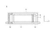
図1は、この発明を実施するための実施の形態1に係るコモンモードチョークコイルを示す斜視図、図2は、実施の形態1に係るコモンモードチョークコイルを示す正面図、図3は、実施の形態1に係るコモンモードチョークコイルを示す下面図、図4は、実施の形態1に係るコモンモードチョークコイルを示す側面図、図5は、実施の形態1に係るコモンモードチョークコイルにおける一対のコイルを示す側面図である。
図1は、この発明を実施するための実施の形態1に係るコモンモードチョークコイルを示す斜視図、図2は、実施の形態1に係るコモンモードチョークコイルを示す正面図、図3は、実施の形態1に係るコモンモードチョークコイルを示す下面図、図4は、実施の形態1に係るコモンモードチョークコイルを示す側面図、図5は、実施の形態1に係るコモンモードチョークコイルにおける一対のコイルを示す側面図である。
図1から図5において、コモンモードチョークコイル1は、U形コア3およびI形コア4からなる磁性体コア2と、第1の極コイルである正極コイル6および第2の極コイルである負極コイル7からなる一対のコイル5と、備える。各図において、X方向は、磁性体コア2の磁路長さ方向である。磁性体コア2の磁路長さ方向は、一対のコイル5の巻線部であるI形コア4を通る磁束の方向であり、I形コア4の長さ方向である。また、Z方向は、X方向と直交する方向であり、U形コア3がI形コア4に連結される方向である。Y方向は、X方向とZ方向との直交する方向である。
U形コア3とI形コア4とは、フェライトなどの磁性材料で構成される。磁性体コア2は、I形コア4がU形コア3の両側脚部を連結するように配置されて、閉磁路に構成されている。正極コイル6と負極コイル7とは、ターン部がX方向に交互に並ぶように、銅製の平角導体を螺旋状にI形コア4に7ターンずつ巻いて構成されている。正極コイル6と負極コイル7は、同じコイル形状に構成され、図4中、Y方向にずれて、I形コア4に巻かれている。これにより、正極コイル6と負極コイル7は、図5に示されるように、X方向から見て、互いに重なる重畳領域である並走部11と、互いに重ならない非重畳領域である非並走部12と、を備える。なお、X方向から見て、正極コイル6と負極コイル7とが互いに重ならない非重畳領域とは、正極コイル6と負極コイル7とがX方向と直交する方向に互いに離れている領域である。なお、X方向とは、螺旋状に巻かれた一対のコイル5のコイル軸方向とも表現できる。
実施の形態1によるコモンモードチョークコイル1においては、一対のコイル5を構成する正極コイル6と負極コイル7とは、ターン部がX方向に交互に並ぶように、I形コア4に螺旋状に巻かれて構成されている。すなわち、一対のコイル5は、バイファイラ巻により構成されている。そこで、コモンモードチョークコイル1は、バイファイラ巻と分割巻とを併用して一対のコイルを構成している特許文献2,3による従来のコモンモードチョークコイルに比べて、X方向の寸法を縮小でき、小型化が図られる。
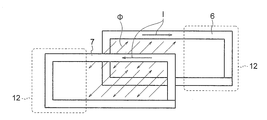
つぎに、正極コイル6と負極コイル7が並走部11と非並走部12とを備えることによる効果について、図6を参照して説明する。図6は、実施の形態1に係るコモンモードチョークコイルのコイルに流れる電流と、それにより生じる磁束を示す模式図である。なお、図6中、Iは電流、Φは磁束を示している。
並走部11においては、電流Iは、正極コイル6と負極コイル7とに逆向きに、かつ近接して流れる。これにより、電流Iが正極コイル6と負極コイル7とを流れることにより発生する磁束Φが互いに打ち消し合い、磁性体コア2の磁気飽和を抑制する。ただし、並走部11は、ノーマルモードインダクタンスへの寄与は小さい。
一方、非並走部12においては、電流Iは、正極コイル6と負極コイル7とに逆向きに、かつ離れて流れる。これにより、電流Iが正極コイル6と負極コイル7とを流れることにより発生する磁束Φの一部が打ち消されずに残り、ノーマルモードインダクタンスに寄与する。ただし、非並走部12は、磁性体コア2の磁気飽和の抑制への寄与は小さい。
このように、コモンモードチョークコイル1においては、一対のコイル5は、磁性体コア2の磁気飽和の抑制に寄与する並走部11と、ノーマルモードインダクタンスに寄与する非並走部12と、を備えている。これにより、コモンモードチョークコイル1は、磁性体コア2の磁気飽和を抑制して、ノーマルモードノイズの低減性能を改善することができる。
ここで、実施の形態1におけるノーマルモードインダクタンスと、特許文献1におけるバイファイラ巻きを一対のコイルに適用した場合のノーマルモードインダクタンスと、を比較する。図7は、1ターンのコイル8の形状を示す模式図である。
1ターンのコイル8の部分自己インダクタンス、および部分相互インダクタンスは、式1で表される。

ここで、i, jは、それぞれ1,2,3,4のいずれかの値をとり、図7に示される区画番号に対応する。Lpijは、i=jのとき、部分自己インダクタンスを示し、i≠jのとき、部分相互インダクタンスを示す。μ0は真空の透磁率、lはコイル8の長さ、dは、i=jのとき、コイル8の幅、i≠jのとき、i番目の区画のコイル8とj番目の区画のコイル8との間の距離である。このとき、1ターンのコイル8のループインダクタンスは、式2で表される。

図7に示されるに、各区画におけるコイル8の幅を2mm、1番目と3番目の区画のコイル8間距離を50mm、2番目と4番目の区画のコイル8間距離を20mmとすると、Lloop=54.8nHとなる。実施の形態1では、正極コイル6と負極コイル7とのターン数が7ターンであり、正極コイル6と負極コイル7との2つのコイルがあることを考慮すると、ノーマルモードインダクタンスは、54.8nH×7×2=767nHとなる。
但し、これは、本実施の形態におけるコイルの並走部11、もしくは特許文献1に示されるバイファイラ巻きにおける隣り合うコイルの影響を考慮していない値である。
但し、これは、本実施の形態におけるコイルの並走部11、もしくは特許文献1に示されるバイファイラ巻きにおける隣り合うコイルの影響を考慮していない値である。
部分相互インダクタンスは、1番目と3番目との区画の組み合わせと、2番目と4番目との区画の組み合わせとのみを計算した。これは、1番目および2番目の区画の組み合わせと、3番目および4番目の区画の組み合わせとにおける部分相互インダクタンスは、ベクトルポテンシャルの向きとコイル8の向きとが直交し、0になるためである。
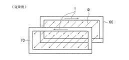
つぎに、隣り合うコイルの影響を考慮してノーマルモードインダクタンスを比較する。図8は、特許文献1に示される従来のコモンモードチョークコイルにおける、隣り合うコイルから鎖交する磁束を示した模式図、図9は、実施の形態1に係るコモンモードチョークコイルにおける、隣り合うコイルから鎖交する磁束を示した模式図である。なお、図8における正極コイル60,70は、正極コイル6と負極コイル7と同一のコイル形状に構成されている。
式3は、コイルのループインダクタンスとコイルを鎖交する磁束との関係を示す。

Φはコイルを鎖交する磁束、Bはコイルを鎖交する磁束密度、sはコイルで囲まれた面、Iはコイルを流れる電流である。
特許文献1による従来のコモンモードチョークコイルにおいては、バイファイラ巻きに巻かれた正極コイル60と負極コイル70とは、X方向から見て、互いに重なっている重畳領域のみを有している。すなわち、従来のコモンモードチョークコイルにおいては、正極コイル60と負極コイル70とは、並走部11のみを有し、非並走部12を有していない。そして、図8に示されるように、隣り合う正極コイル60と負極コイル70とに流れる電流Iは逆向きであり、鎖交する磁束Φは逆向きとなる。これにより、隣り合う正極コイル60と負極コイル70とに鎖交する磁束Φは、互いに打ち消される。正極コイル60と負極コイル70とを鎖交する全磁束Φに対する、打ち消される磁束Φの割合をnとすると、Lloopの値、すなわちノーマルモードインダクタンスは、(1-n)倍となる。但し、nは、0<n<1である。例えば、n=0.9とすると、上記式2から算出したノーマルモードインダクタンスは、767nH×(1-0.9)=76.7nHとなる。
実施の形態1によるコモンモードチョークコイル1においては、正極コイル6と負極コイル7とが並走部11と非並走部12とを備えているので、隣り合う正極コイル6と負極コイル7との対向面積は、非並走部12が存在する分小さくなる。ここで、非並走部12の存在により、隣り合う正極コイル6と負極コイル7との対向面積が、並走部11のみを有する隣り合う正極コイル60,70の対向面積のm倍になったとする。その結果、隣り合う正極コイル6と負極コイル7とに鎖交する全磁束Φに対する打ち消される磁束Φの割合は、(n×m)倍となる。但し、mは、0<m<1である。実施の形態1では、正極コイル6と負極コイル7との対向面積は、非並走部12を設けることで、特許文献1において正極コイル60,70の対向面積が20mm×50mmであったものが、20mm×45mmとなった。そこで、m=0.9となる。実施の形態1においてもn=0.9とすると、ノーマルモードインダクタンスは、767nH×(1-0.9×0.9)=146nHとなる。このように、実施の形態1によれば、一対のコイルに並走部11のみを有するバイファイラ巻きを適用した特許文献1に比べて、ノーマルモードインダクタンスを改善できることがわかる。
ここでは、計算の簡単化のため、磁束密度Bが正極コイル6と負極コイル7とで囲われた面に対して垂直で、位置によらず一定とした。
以上のように、実施の形態1によれば、一対のコイル5は、ターン部がX方向に交互に並ぶように、磁性体コア2のI形コア4に螺旋状に巻かれた正極コイル6と負極コイル7とからなる。正極コイル6と負極コイル7とは、磁気飽和抑制に寄与する並走部11と、ノーマルモードインダクタンスに寄与する非並走部12と、を備える。これにより、磁性体コア2をX方向に伸長することなく、磁気飽和を抑制でき、ノーマルモードノイズの低減性能を改善することが可能となる、小型のコモンモードチョークコイル1を実現できる。
なお、上記実施の形態1では、正極コイル6と負極コイル7とが同じコイル形状に構成されているものとしているが、正極コイル6と負極コイル7とは、異なるコイル形状に構成されてよい。
また、上記実施の形態1では、隣り合う正極コイル6と負極コイル7とは、7ターンの全てにおいて、並走部11と非並走部12とを備えているが、隣り合う正極コイル6と負極コイル7とは、7ターンのなかの少なくとも1ターンにおいて、並走部11と非並走部12とを備えていればよい。
また、上記実施の形態1では、隣り合う正極コイル6と負極コイル7とは、7ターンの全てにおいて、並走部11と非並走部12とを備えているが、隣り合う正極コイル6と負極コイル7とは、7ターンのなかの少なくとも1ターンにおいて、並走部11と非並走部12とを備えていればよい。
実施の形態2.
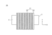
図10は、この発明を実施するための実施の形態2に係るコモンモードチョークコイルを示す正面図、図11は、実施の形態2に係るコモンモードチョークコイルを示す下面図、図12は、実施の形態2に係るコモンモードチョークコイルにおける一対のコイルを示す側面図、図13は、実施の形態2に係るコモンモードチョークコイルにおける一対のコイルと金属筐体とを示す側面図、図14は、比較例のコモンモードチョークコイルにおける一対のコイルと金属筐体とを示す側面図である。
図10は、この発明を実施するための実施の形態2に係るコモンモードチョークコイルを示す正面図、図11は、実施の形態2に係るコモンモードチョークコイルを示す下面図、図12は、実施の形態2に係るコモンモードチョークコイルにおける一対のコイルを示す側面図、図13は、実施の形態2に係るコモンモードチョークコイルにおける一対のコイルと金属筐体とを示す側面図、図14は、比較例のコモンモードチョークコイルにおける一対のコイルと金属筐体とを示す側面図である。
図10から図12において、一対のコイル21は、第1の極コイルである正極コイル22と第2の極コイルである負極コイル23とを備える。正極コイル22のターン部は、負極コイル23のターン部よりZ方向に大きい形状に構成されている。正極コイル22と負極コイル23は、ターン部がX方向に交互に並ぶように、I形コア4に7ターンずつ巻かれている。金属部材である金属筐体25が、Z方向のI形コア4のU形コア3と反対側に配置されている。そして、正極コイル22と負極コイル23は、Z方向のI形コア4のU形コア3と反対側に位置する外周部を金属筐体25に平板状の絶縁体24を介して接するように配置されて、金属筐体25に保持されている。そこで、正極コイル22は、負極コイル23に対して、Z方向の金属筐体25と反対側に突出している。これにより、正極コイル22と負極コイル23は、図12に示されるように、X方向から見て、互いに重なる重畳領域である並走部11と、互いに重ならない非重畳領域である非並走部12と、を備える。ここで、金属筐体25には、銅、鉄、アルミニウムなどの金属材料が用いられる。
なお、他の構成は、上記実施の形態1と同様に構成されている。
なお、他の構成は、上記実施の形態1と同様に構成されている。
実施の形態2によるコモンモードチョークコイル1Aでは、正極コイル22と負極コイル23とは、ターン部がX方向に交互に並ぶように、磁性体コア2のI形コア4に螺旋状に巻かれている。また、正極コイル22と負極コイル23とは、磁気飽和抑制に寄与する並走部11と、ノーマルモードインダクタンスに寄与する非並走部12と、を備える。したがって、実施の形態2においても、上記実施の形態1と同様の効果が得られる。
並走部11では、電流が隣り合う正極コイル22と負極コイル23とに流れることにより発生する磁束Φは、互いに打ち消しあう。一方、非並走部12では、電流が隣り合う正極コイル22と負極コイル23とに流れることにより発生する磁束Φは、互いに打ち消しあわない。そのため、図13および図14に示されるように、漏れ磁束が生じる。
比較例のコモンモードチョークコイルにおいては、図14に示されるように、一対のコイル21Aにおける非並走部12が金属筐体25に近い位置に配置されている。そこで、漏れ磁束が金属筐体25に鎖交するため、漏れ磁束が遮蔽されるので、ノーマルモードインダクタンスへの寄与が小さくなる。
一方、実施の形態2によるコモンモードチョークコイル1Aでは、図13に示めされるように、一対のコイル21における非並走部12が金属筐体25から離れた位置に配置されている。そこで、漏れ磁束が金属筐体25に鎖交しないため、漏れ磁束が遮蔽されることがないので、ノーマルモードインダクタンスへの寄与が大きくなる。
このように、実施の形態2によれば、一対のコイル21における非並走部12が、金属筐体25から離れた位置に配置されている。そこで、非並走部12における漏れ磁束が金属筐体25に鎖交しないので、漏れ磁束が金属筐体25に鎖交する場合に比べて、ノーマルモードインダクタンスの改善がより効果的になる。
なお、上記実施の形態2では、金属筐体25が一対のコイル21のI形コア4のU形コア3と反対側に配置されているが、金属筐体25は、一対のコイル21のI形コア4のU形コア3側、又は一対のコイル21のY方向の片側に配置されてもよい。この場合においても、非並走部12は、I形コア4の金属筐体25と反対側に配置される。
また、上記実施の形態2では、一対のコイル21を保持する金属部材として専用の金属筐体25を用いているが、金属部材は、コモンモードチョークコイルを実装する装置の筐体、コモンモードチョークコイルを冷却するヒートシンク、コモンモードチョークコイルを実装する基板のグラウンドなどを用いてもよい。この場合においても、一対のコイルは、絶縁体を介してこれらの金属部材に保持される。また、一対のコイル21の非並走部12は、I形コアの筐体、ヒートシンク、基板のグランドなどの金属部材と反対側に配置されていればよい。
実施の形態3.
図15は、この発明を実施するための実施の形態3に係るコモンモードチョークコイルを示す側面図である。
図15は、この発明を実施するための実施の形態3に係るコモンモードチョークコイルを示す側面図である。
図15において、矩形の四角柱に構成された補助磁性体コア30が、非並走部12の正極コイル6と負極コイル7とで囲まれた空間内に、当該空間のX方向の一端から他端に至るように挿入されている。
なお、他の構成は、上記実施の形態1と同様に構成されている。
なお、他の構成は、上記実施の形態1と同様に構成されている。
実施の形態3によるコモンモードチョークコイル1Bにおいても、正極コイル6と負極コイル7とは、ターン部がX方向に交互に並ぶように、磁性体コア2のI形コア4に螺旋状に巻かれている。また、正極コイル6と負極コイル7とは、磁気飽和抑制に寄与する並走部11と、ノーマルモードインダクタンスに寄与する非並走部12と、を備える。したがって、実施の形態3においても、上記実施の形態1と同様の効果が得られる。
コモンモードチョークコイル1Bでは、補助磁性体コア30が、非並走部12の正極コイル6と負極コイル7とで囲まれた空間内に配置されている。これにより、実施の形態3によるコモンモードチョークコイル1Bは、補助磁性体コア30が非並走部12の正極コイル6と負極コイル7とで囲まれた空間内に配置されていない実施の形態1に比べ、体積を増加させることなく、より効果的にノーマルモードインダクタンスを改善できる。
なお、上記実施の形態3では、実施の形態1によるコモンモードチョークコイル1における非並走部12の正極コイル6と負極コイル7とで囲まれた空間内に補助磁性体コア30を配置しているが、他の実施の形態によるコモンモードチョークコイルにおける非並走部の正極コイルと負極コイルとで囲まれた空間内に補助磁性体コア30を配置しても、同様の効果が得られる。
また、実施の形態3において、補助磁性体コア30は磁性体コア2と同じ磁性材料で構成してもよいし、異なる磁性材料で構成してもよい。
実施の形態4.
図16は、この発明を実施するための実施の形態4に係るコモンモードチョークコイルを示す側面図である。
図16は、この発明を実施するための実施の形態4に係るコモンモードチョークコイルを示す側面図である。
図16において、矩形の四角筒体の構造を有する放熱部材である金属板31が、非並走部12の正極コイル6と負極コイル7とで囲まれた空間内に、当該空間のX方向の一端から他端に至るように挿入されている。さらに、金属板31は、絶縁体32を介して当該空間を構成する正極コイル6および負極コイル7の内周壁面に接する状態で、当該空間に挿入されている。ここで、金属板31には、銅、鉄、アルミニウムなどの金属材料が用いられる。
なお、他の構成は、上記実施の形態1と同様に構成されている。
なお、他の構成は、上記実施の形態1と同様に構成されている。
実施の形態4によるコモンモードチョークコイル1Cにおいても、正極コイル6と負極コイル7とは、ターン部がX方向に交互に並ぶように、磁性体コア2のI形コア4に螺旋状に巻かれている。また、正極コイル6と負極コイル7とは、磁気飽和抑制に寄与する並走部11と、ノーマルモードインダクタンスに寄与する非並走部12と、を備える。したがって、実施の形態4においても、上記実施の形態1と同様の効果が得られる。
コモンモードチョークコイル1Cでは、金属板31が、非並走部12の正極コイル6と負極コイル7とで囲まれた空間内に、絶縁体32を介して正極コイル6および負極コイル7に接するように配置されている。これにより、実施の形態4によるコモンモードチョークコイル1Cは、金属板31が非並走部12の正極コイル6と負極コイル7とで囲まれた空間内に配置されていない実施の形態1に比べ、体積を増加させることなく、一対のコイル5の放熱性を改善することができる。また、金属板31は、非並走部12から生じる漏れ磁束を遮蔽しないので、非並走部12を設けることによるノーマルモードインダクタンスを改善する効果を阻害しない。
なお、上記実施の形態4では、実施の形態1によるコモンモードチョークコイル1における非並走部12の正極コイル6と負極コイル7とで囲まれた空間内に金属板31を挿入しているが、他の実施の形態によるコモンモードチョークコイルにおける非並走部の正極コイルと負極コイルとで囲まれた空間内に金属板31を挿入しても、同様の効果が得られる。
また、上記実施の形態4では、金属板31の内部を空洞としているが、金属板31内に樹脂材料を充填してもよく、実施の形態3における補助磁性体コア30を金属板31内に挿入してもよい。
また、上記実施の形態1-4では、正極コイルと負極コイルとは、ターン部がX方向に交互に並ぶように、I形コアに螺旋状に7ターンずつ巻かれているが、正極コイルと負極コイルとは、7ターン限定されず、複数ターンであればよい。
実施の形態5.
図17は、この発明を実施するための実施の形態5に係るコモンモードチョークコイルを示す正面図、図18は、実施の形態5に係るコモンモードチョークコイルを示す下面図である。
図17は、この発明を実施するための実施の形態5に係るコモンモードチョークコイルを示す正面図、図18は、実施の形態5に係るコモンモードチョークコイルを示す下面図である。
図17および図18において、正極コイル6と負極コイル7とは、7ターンのうち、6ターンがX方向に交互に並ぶように、銅製の平角導体を螺旋状にI形コア4に巻いて構成されている。
なお、他の構成は、上記実施の形態1と同様に構成されている。
なお、他の構成は、上記実施の形態1と同様に構成されている。
実施の形態5によるコモンモードチョークコイル1Dでは、正極コイル6と負極コイル7とは、ターン部がX方向に交互に並ぶように、磁性体コア2のI形コア4に螺旋状に巻かれている。また、正極コイル6と負極コイル7とは、磁気飽和抑制に寄与する並走部11と、ノーマルモードインダクタンスに寄与する非並走部12と、を備える。したがって、実施の形態5においても、上記実施の形態1と同様の効果が得られる。
コモンモードチョークコイル1Dでは、正極コイル6と負極コイル7とが、X方向に1ターン分ずれて、I形コア4に配置されている。すなわち、正極コイル6と負極コイル7とが、バイファイラ巻きと分割巻きとを併用して構成されているので、磁気飽和を抑制しつつ、ノーマルモードノイズの低減性能を改善することができる。
上記実施の形態5では、正極コイル6と負極コイル7とは、全7ターンのうち、6ターンがX方向に交互に並ぶように配置され、残る1ターンが自身のコイルと隣り合うように配置されている。すなわち、正極コイル6と負極コイル7とは、全7ターンのうち、6ターンが異なる極のコイルと隣り合うように配置され、残る1ターンが同じ極のコイルと隣り合うように配置されている。しかし、全7ターンのうち、異なる極のコイルが隣り合うターン数は6ターンに限定されず、6ターンから1ターンであればよい。また、正極コイル6と負極コイル7のターン数は7ターンに限定されない。すなわち、正極コイル6と負極コイル7とは、全Nターンのうち、Mターンが異なる極のコイルと隣り合うように配置され、(N-M)ターンが同じ極のコイルと隣り合うように配置されればよい。但し、Nは2以上の整数、Mは1以上、(N-1)以下の整数である。
ここで、正極コイル6と負極コイル7とが並走部11のみを備えている場合には、ノーマルモードインダクタンスの調整が、ターン数NとMの比でしか調整できない。その結果、ノーマルモードインダクタンスは、離散的な値しか取れない。
実施の形態5では、正極コイル6と負極コイル7とが並走部11と非並走部12とを備えているので、ノーマルモードインダクタンスを任意の値に調整可能となる。
なお、上記実施の形態5では、実施の形態1によるコモンモードチョークコイル1における正極コイル6と負極コイル7を、全7ターンのうち、6ターンがX方向に交互に並ぶように配置され、残る1ターンが同じ極のコイルと隣り合うように配置しているが、他の実施の形態によるコモンモードチョークコイルにおける正極コイルと負極コイルを、全7ターンのうち、6ターンがX方向に交互に並ぶように配置され、残る1ターンが同じ極のコイルと隣り合うように配置しても、同様の効果が得られる。
実施の形態6.
図19は、この発明を実施するための実施の形態6に係るコモンモードチョークコイルにおける一対のコイルを示す斜視図、図20は、実施の形態6に係るコモンモードチョークコイルにおける一対のコイルを示す側面図である。
図19は、この発明を実施するための実施の形態6に係るコモンモードチョークコイルにおける一対のコイルを示す斜視図、図20は、実施の形態6に係るコモンモードチョークコイルにおける一対のコイルを示す側面図である。
図19および図20に示されるように、一対のコイル40は、1ターンの第1の極コイルである正極コイル41と、1ターンの第2の極コイルである負極コイル42と、を備える。正極コイル41と負極コイル42とは、図示されていないが、隣り合うように磁性体コアの巻線部であるI形コアに巻かれている。さらに、正極コイル41と負極コイル42とは、X方向から見て、互いに重なる重畳領域である並走部11と、互いに重ならない非重畳領域である非並走部12と、を備える。
なお、他の構成は、上記実施の形態1と同様に構成されている。
なお、他の構成は、上記実施の形態1と同様に構成されている。
実施の形態6においても、それぞれ1ターンの正極コイル41と負極コイル42とが、X方向に隣り合うように磁性体コアのI形コアに巻かれている。また、正極コイル41と負極コイル42とは、1ターンのなかで、磁気飽和抑制に寄与する並走部11と、ノーマルモードインダクタンスに寄与する非並走部12と、を備える。したがって、実施の形態6においても、上記実施の形態1と同様の効果が得られる。
なお、実施の形態6で説明したように、正極コイルと負極コイルとが1ターンである場合においても、本発明の効果が得られる。したがって、本発明は、正極コイルと負極コイルとは、I形コアの長さ方向に螺旋状に1ターン以上巻かれ、正極コイルと負極コイルとは、1ターン以上が隣り合うようにI形コアに配置され、隣り合う正極コイルと負極コイルとの少なくとも1ターンにおいて、並走部と非並走部とを備えていればよい。
また、上記実施の形態6においても、上記実施の形態2と同様に、金属筐体25が一対のコイル40における非並走部12から離れた位置に配置されてもよい。
また、上記実施の形態6においても、補助磁性体コア30が、非並走部12の正極コイル41と負極コイル42とで囲まれた空間内に挿入されてもよい。
さらに、上記実施の形態6においても、金属板31が、非並走部12の正極コイル41と負極コイル42とで囲まれた空間内に、絶縁体32を介して正極コイル41および負極コイル42に接するように配置されてもよい。
また、上記実施の形態6においても、補助磁性体コア30が、非並走部12の正極コイル41と負極コイル42とで囲まれた空間内に挿入されてもよい。
さらに、上記実施の形態6においても、金属板31が、非並走部12の正極コイル41と負極コイル42とで囲まれた空間内に、絶縁体32を介して正極コイル41および負極コイル42に接するように配置されてもよい。
また、上記各実施の形態では、U形コアとI形コアとから構成されている磁性体コアを用いているが、磁性体コアは、U形コアとI形コアとを組み合わせたコアに限定されず、例えば、U形コアとU形コアとを組み合わせたコア、トロイダルコアなどを用いてもよい。
また、上記各実施の形態では、正極コイルおよび負極コイルの材料として、銅製の平角導体を用いているが、他の良導電性の材料、例えばアルミ製の平角導体を用いてもよい。また、正極コイルおよび負極コイルの材料として平角導体を用いているが、円形断面の導体を用いてもよい。
また、上記各実施の形態では、正極コイルおよび負極コイルは、矩形筒状のコイル形状に構成されているが、コイル形状は、矩形筒状に限定されない。
2 磁性体コア、4 I形コア(巻線部)、5 一対のコイル、6 正極コイル、7 負極コイル、11 並走部、12 非並走部、21 一対のコイル、22 正極コイル、23 負極コイル、25 金属筐体(金属部材)、30 補助磁性体コア、31 金属板(放熱部材)、40 一対のコイル、41 正極コイル、42 負極コイル。
Claims (5)
- 磁性体コアと、
上記磁性体コアの巻線部に巻かれた一対のコイルと、を備え、
上記一対のコイルは、それぞれ、上記巻線部に上記巻線部の長さ方向に螺旋状にNターン巻かれた第1の極コイルと第2の極コイルとを備え、
上記第1の極コイルと第2の極コイルとは、上記Nターンのうち、1ターン以上が隣り合うように上記巻線部に配置されており、隣り合う上記第1の極コイルと上記第2の極コイルとの少なくとも1ターンにおいて、上記巻線部の長さ方向から見て、互いに重なる並走部と、上記巻線部の長さ方向と直交する方向に互いに離れる非並走部と、を備え、但し、Nは1以上の整数であるコモンモードチョークコイル。 - 上記巻線部の長さ方向から見て、上記巻線部の一方の側に位置する上記一対のコイルの外周部を保持する金属部材をさらに備え、
上記非並走部は、上記一対のコイルの上記巻線部の上記金属部材と反対側に配置されている請求項1記載のコモンモードチョークコイル。 - 上記金属部材は、上記一対のコイルを冷却するヒートシンクである請求項2記載のコモンモードチョークコイル。
- 補助磁性体コアが、上記非並走部で囲まれた空間内に挿入されている請求項1から請求項3のいずれか1項に記載のコモンモードチョークコイル。
- 放熱部材が、上記非並走部で囲まれた空間内に挿入されている請求項1から請求項3のいずれか1項に記載のコモンモードチョークコイル。
Priority Applications (4)
| Application Number | Priority Date | Filing Date | Title |
|---|---|---|---|
| DE112019003205.4T DE112019003205T5 (de) | 2018-06-28 | 2019-01-17 | Gleichtakt-drosselspule |
| JP2019524484A JP6593834B1 (ja) | 2018-06-28 | 2019-01-17 | コモンモードチョークコイル |
| CN201980041264.2A CN112313764B (zh) | 2018-06-28 | 2019-01-17 | 共模扼流线圈 |
| US17/049,036 US11749439B2 (en) | 2018-06-28 | 2019-07-17 | Common mode choke coil |
Applications Claiming Priority (2)
| Application Number | Priority Date | Filing Date | Title |
|---|---|---|---|
| JP2018123064 | 2018-06-28 | ||
| JP2018-123064 | 2018-06-28 |
Publications (1)
| Publication Number | Publication Date |
|---|---|
| WO2020003565A1 true WO2020003565A1 (ja) | 2020-01-02 |
Family
ID=68986181
Family Applications (1)
| Application Number | Title | Priority Date | Filing Date |
|---|---|---|---|
| PCT/JP2019/001323 Ceased WO2020003565A1 (ja) | 2018-06-28 | 2019-01-17 | コモンモードチョークコイル |
Country Status (3)
| Country | Link |
|---|---|
| US (1) | US11749439B2 (ja) |
| DE (1) | DE112019003205T5 (ja) |
| WO (1) | WO2020003565A1 (ja) |
Cited By (2)
| Publication number | Priority date | Publication date | Assignee | Title |
|---|---|---|---|---|
| JP2021141223A (ja) * | 2020-03-06 | 2021-09-16 | 株式会社トーキン | リアクトル |
| WO2025134507A1 (ja) * | 2023-12-19 | 2025-06-26 | 株式会社Ihi | コモンモードフィルタ回路 |
Families Citing this family (2)
| Publication number | Priority date | Publication date | Assignee | Title |
|---|---|---|---|---|
| JP6956925B2 (ja) * | 2019-05-24 | 2021-11-02 | 三菱電機株式会社 | ノイズ低減素子 |
| JP7468275B2 (ja) * | 2020-09-29 | 2024-04-16 | 株式会社豊田自動織機 | ノイズフィルタ |
Citations (4)
| Publication number | Priority date | Publication date | Assignee | Title |
|---|---|---|---|---|
| JPH10163046A (ja) * | 1996-12-02 | 1998-06-19 | Matsushita Electric Ind Co Ltd | ノイズフィルタ |
| JP2005166791A (ja) * | 2003-12-01 | 2005-06-23 | Taiyo Yuden Co Ltd | 積層チップコモンモードチョークコイル |
| JP2007027445A (ja) * | 2005-07-15 | 2007-02-01 | Murata Mfg Co Ltd | 積層コモンモードチョークコイル |
| JP2019009152A (ja) * | 2017-06-20 | 2019-01-17 | スミダコーポレーション株式会社 | エッジワイズコイル、リアクトル及びリアクトル製造方法 |
Family Cites Families (6)
| Publication number | Priority date | Publication date | Assignee | Title |
|---|---|---|---|---|
| JPH0729755A (ja) | 1993-07-14 | 1995-01-31 | Top Denshi Kk | コモンモードチョークコイル |
| JPH11214229A (ja) | 1998-01-23 | 1999-08-06 | Kankyo Denji Gijutsu Kenkyusho:Kk | コモンモードチョークコイル |
| JP2002246244A (ja) | 2001-02-15 | 2002-08-30 | Murata Mfg Co Ltd | チョークコイル |
| US7385466B2 (en) * | 2004-03-30 | 2008-06-10 | Matsushita Electric Industrial Co., Ltd. | Differential transmission circuit and common mode choke coil |
| JP4797549B2 (ja) * | 2005-10-05 | 2011-10-19 | Tdk株式会社 | コモンモードチョークコイル及びその製造方法 |
| CN105706196B (zh) | 2013-11-08 | 2018-04-10 | 三菱电机株式会社 | 电磁感应设备 |
-
2019
- 2019-01-17 WO PCT/JP2019/001323 patent/WO2020003565A1/ja not_active Ceased
- 2019-01-17 DE DE112019003205.4T patent/DE112019003205T5/de not_active Withdrawn
- 2019-07-17 US US17/049,036 patent/US11749439B2/en active Active
Patent Citations (4)
| Publication number | Priority date | Publication date | Assignee | Title |
|---|---|---|---|---|
| JPH10163046A (ja) * | 1996-12-02 | 1998-06-19 | Matsushita Electric Ind Co Ltd | ノイズフィルタ |
| JP2005166791A (ja) * | 2003-12-01 | 2005-06-23 | Taiyo Yuden Co Ltd | 積層チップコモンモードチョークコイル |
| JP2007027445A (ja) * | 2005-07-15 | 2007-02-01 | Murata Mfg Co Ltd | 積層コモンモードチョークコイル |
| JP2019009152A (ja) * | 2017-06-20 | 2019-01-17 | スミダコーポレーション株式会社 | エッジワイズコイル、リアクトル及びリアクトル製造方法 |
Cited By (3)
| Publication number | Priority date | Publication date | Assignee | Title |
|---|---|---|---|---|
| JP2021141223A (ja) * | 2020-03-06 | 2021-09-16 | 株式会社トーキン | リアクトル |
| JP7437193B2 (ja) | 2020-03-06 | 2024-02-22 | 株式会社トーキン | リアクトル |
| WO2025134507A1 (ja) * | 2023-12-19 | 2025-06-26 | 株式会社Ihi | コモンモードフィルタ回路 |
Also Published As
| Publication number | Publication date |
|---|---|
| US20210327629A1 (en) | 2021-10-21 |
| DE112019003205T5 (de) | 2021-03-11 |
| US11749439B2 (en) | 2023-09-05 |
Similar Documents
| Publication | Publication Date | Title |
|---|---|---|
| KR0165948B1 (ko) | 초크 코일 | |
| WO2020003565A1 (ja) | コモンモードチョークコイル | |
| US11688541B2 (en) | Integrated magnetic component | |
| US20060152325A1 (en) | Magnetic core type laminated inductor | |
| US10224141B2 (en) | Coupled inductor | |
| US10804709B2 (en) | Coil unit, and power transmitting device, power receiving device and wireless power transmission system using the coil unit | |
| US20150109090A1 (en) | Electrical transformer with a shielded cast coil assembly | |
| JPH08181018A (ja) | コイル装置 | |
| CN117253700A (zh) | 变压器 | |
| JP6593834B1 (ja) | コモンモードチョークコイル | |
| US20100188184A1 (en) | Inductor and core member thereof | |
| CN113574619A (zh) | 漏磁变压器 | |
| JP2019009177A (ja) | 磁性被覆コイル及びこれを用いたトランス | |
| US20180040408A1 (en) | Reactor | |
| CN1185011A (zh) | 扼流圈 | |
| KR20040024724A (ko) | 트랜스포머 및 이를 구비하는 전기 기기 | |
| KR102735137B1 (ko) | 소형화된 가변 인덕터 | |
| JP6424710B2 (ja) | 非接触電力伝送用コイルおよび非接触電力伝送装置 | |
| JP6823130B2 (ja) | フィルタ装置 | |
| JP2002164235A (ja) | リーケージトランス、電源装置および照明器具 | |
| KR102075955B1 (ko) | 투인원 평면 인덕터 | |
| JPH08316038A (ja) | 偏平形積層トランス | |
| JP6376317B1 (ja) | アンテナ装置および電子機器 | |
| KR20230009602A (ko) | 자속 차폐 기능이 구비된 코어 타입 코일부품 | |
| JP7122137B2 (ja) | ワイヤレス給電用電気ユニット |
Legal Events
| Date | Code | Title | Description |
|---|---|---|---|
| ENP | Entry into the national phase |
Ref document number: 2019524484 Country of ref document: JP Kind code of ref document: A |
|
| 121 | Ep: the epo has been informed by wipo that ep was designated in this application |
Ref document number: 19825252 Country of ref document: EP Kind code of ref document: A1 |
|
| 122 | Ep: pct application non-entry in european phase |
Ref document number: 19825252 Country of ref document: EP Kind code of ref document: A1 |