WO2020003426A1 - 温度計測システム、温度計測方法、及び、プログラム - Google Patents
温度計測システム、温度計測方法、及び、プログラム Download PDFInfo
- Publication number
- WO2020003426A1 WO2020003426A1 PCT/JP2018/024472 JP2018024472W WO2020003426A1 WO 2020003426 A1 WO2020003426 A1 WO 2020003426A1 JP 2018024472 W JP2018024472 W JP 2018024472W WO 2020003426 A1 WO2020003426 A1 WO 2020003426A1
- Authority
- WO
- WIPO (PCT)
- Prior art keywords
- temperature
- route
- information
- storage
- identification information
- Prior art date
- Legal status (The legal status is an assumption and is not a legal conclusion. Google has not performed a legal analysis and makes no representation as to the accuracy of the status listed.)
- Ceased
Links
Images





Classifications
-
- B—PERFORMING OPERATIONS; TRANSPORTING
- B65—CONVEYING; PACKING; STORING; HANDLING THIN OR FILAMENTARY MATERIAL
- B65G—TRANSPORT OR STORAGE DEVICES, e.g. CONVEYORS FOR LOADING OR TIPPING, SHOP CONVEYOR SYSTEMS OR PNEUMATIC TUBE CONVEYORS
- B65G1/00—Storing articles, individually or in orderly arrangement, in warehouses or magazines
-
- B—PERFORMING OPERATIONS; TRANSPORTING
- B65—CONVEYING; PACKING; STORING; HANDLING THIN OR FILAMENTARY MATERIAL
- B65G—TRANSPORT OR STORAGE DEVICES, e.g. CONVEYORS FOR LOADING OR TIPPING, SHOP CONVEYOR SYSTEMS OR PNEUMATIC TUBE CONVEYORS
- B65G1/00—Storing articles, individually or in orderly arrangement, in warehouses or magazines
- B65G1/02—Storage devices
- B65G1/04—Storage devices mechanical
- B65G1/137—Storage devices mechanical with arrangements or automatic control means for selecting which articles are to be removed
Definitions
- the present invention relates to a temperature measurement system, a temperature measurement method, and a program.
- Patent Literature 1 discloses a technique in which a temperature sensor is provided on a transporter provided in a stacker crane as a transport device, and the temperature of the stored object is measured by the temperature sensor.
- the portable device is moved to a position of a storage object requiring temperature measurement, and the temperature of the stored object is measured in a non-contact manner using a temperature sensor provided in the portable device.
- the measured temperature data indicating the measured temperature is transmitted to a data accumulator installed on the ground via a control unit provided in the stacker crane.
- a temperature sensor for measuring the temperature of the stored object is provided in the portable device. For this reason, in order to stabilize the measured value of the temperature sensor, it is necessary to stop the transporter in front of the stored object, and the temperature of the stored object cannot be measured efficiently in a short time. For this reason, a technique for efficiently measuring the temperatures of a plurality of storage areas included in a rack shelf in a short time is desired.
- the present invention has been made in view of the above problems, and has as its object to provide a temperature measurement system, a temperature measurement method, and a program for efficiently and quickly measuring the temperatures of a plurality of storage areas included in a rack shelf.
- a temperature measurement system includes: An automatic transport device including: a rack shelf having a plurality of storage areas; a transport machine that loads articles stored in any of the plurality of storage areas; and a transport device that moves the transport machine in accordance with a control signal.
- An automatic transport device including: a rack shelf having a plurality of storage areas; a transport machine that loads articles stored in any of the plurality of storage areas; and a transport device that moves the transport machine in accordance with a control signal.
- a temperature measurement system that measures the temperature of the plurality of storage areas, A temperature sensor installed in each of the plurality of storage areas, for measuring a temperature of the storage area, identification information storage means for storing identification information for identifying the storage area, and receiving the first radio wave Using a power generated from the first radio wave in response, transmitting a second radio wave including temperature information indicating the temperature measured by the temperature sensor and the identification information stored in the identification information storage means.
- a temperature measuring device comprising: a radio wave transmitting / receiving means; The second radio wave transmitted by the temperature measuring device closest to the portable device among the plurality of temperature measuring devices installed in the transport device and transmitting the first radio wave, among the plurality of temperature measuring devices installed in the plurality of storage areas.
- a reading device that receives the temperature information and the identification information included in the second radio wave,
- a temperature information collection device that collects the temperature information and the identification information acquired by the reading device.
- a temperature sensor that measures the temperature of the storage area, identification information storage means that stores identification information for identifying the storage area, and a temperature sensor generated from the first radio wave in response to receiving the first radio wave
- a reading device that receives the second radio wave transmitted by the temperature measurement device closest to the second radio wave and acquires the temperature information and the identification information included in the second radio wave is installed in the portable device. Therefore, according to the present invention, it is possible to efficiently measure the temperatures of a plurality of storage areas included in a rack shelf in a short time.
- Configuration diagram of an automatic warehouse according to Embodiment 1 of the present invention 1 is a configuration diagram of a route instruction device according to a first embodiment of the present invention.
- FIG. 1 is a configuration diagram of a temperature information collection device according to a first embodiment of the present invention.
- Functional configuration diagram of the temperature measurement system according to the first embodiment of the present invention 1 is a configuration diagram of a temperature measuring device, a reading device, and a control unit according to a first embodiment of the present invention.
- 9 is a flowchart illustrating article storage processing executed by the route instruction device according to the first embodiment of the present invention.
- FIG. 1 is a first diagram illustrating a state where an article is taken out of a rack shelf by a transporter.
- FIG. 2 is a second diagram illustrating a state where an article is taken out of a rack shelf by a transporter.
- FIG. 3 is a third diagram illustrating a state where an article is taken out of a rack shelf by a transporter.
- FIG. 4 is a fourth diagram illustrating a state where an article is taken out of a rack shelf by a transporter.
- Flowchart showing the route determination processing shown in FIG. FIG. 4 is a diagram showing a plurality of candidate routes according to the first embodiment of the present invention. Explanatory drawing of the moving route determination method according to the first embodiment of the present invention. Explanatory drawing of the moving route determination method according to the second embodiment of the present invention. The figure which shows the some candidate route based on Embodiment 3 of this invention.
- 11 is a flowchart illustrating a temperature measurement process executed by the route instruction device according to the fourth embodiment of the present invention.
- the automatic warehouse 2000 incorporates a temperature measurement system 1000 shown in FIG.
- the automatic warehouse 2000 is a warehouse in which article management is automated by computer control.
- the automatic warehouse 2000 is, for example, a freezing warehouse that automatically manages articles to be stored at a low temperature.
- the automatic warehouse 2000 mainly has a transport function of transporting an article to a desired place and a temperature measuring function of measuring a temperature of an area where the article is arranged. Then, in order to efficiently measure the temperature of the area where the articles are arranged, the automatic warehouse 2000 mainly measures the temperature of this area when the articles are transported.
- the automatic warehouse 2000 has, for example, a refrigeration function of keeping the articles at a low temperature by a refrigerator (not shown), but the description of the refrigeration function is omitted.
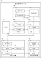
- the automatic warehouse 2000 includes a route instruction device 100, a temperature information collection device 200, a rack shelf 300, and a transport device 400.
- the route instruction device 100 determines the movement route of the transporter 410 included in the transport device 400, and transmits route information indicating the determined travel route to the control unit 440 included in the transport device 400. Further, the route instruction device 100 receives the temperature information and the identification information from the control unit 440, and transmits the received temperature information and the identification information to the temperature information collection device 200.
- the temperature information is information indicating the temperature obtained by measuring the temperature of one storage area 310 among the plurality of storage areas 310 provided in the rack shelf 300.
- the identification information is information for identifying the storage area 310 where the temperature has been measured.
- the route instruction device 100 determines the movement route of the transporter 410 so that the storage area 310 in which the temperature is not measured for a long period of time is not generated as much as possible.
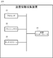
- the route instruction device 100 includes a processor 11, a flash memory 12, a touch screen 13, a first communication interface 14, and a second communication interface 15.
- the processor 11 controls the entire operation of the route instruction device 100.
- the processor 11 is, for example, a CPU (Central Processing Unit) incorporating a ROM (Read Only Memory), a RAM (Random Access Memory), an RTC (Real Time Clock), and the like.
- the CPU operates according to a basic program stored in a ROM, for example, and uses a RAM as a work area.
- the flash memory 12 is a nonvolatile memory for storing various information.
- the flash memory 12 stores, for example, a program executed by the processor 11.
- the touch screen 13 detects an operation performed by the user, and supplies a signal indicating a result of the detection to the processor 11.
- the touch screen 13 displays information according to the control of the processor 11.
- the first communication interface 14 is a communication interface that enables the route instruction device 100 to communicate with the control unit 440.
- the first communication interface 14 may be a communication interface for wireless communication such as a wireless LAN (Local Area Network), Wi-Fi, or Bluetooth (registered trademark), or may be a USB (Universal Serial Bus) or a USB (Universal Serial Bus).
- a communication interface for wired communication such as IEEE1394 may be used.
- the second communication interface 15 is a communication interface for enabling the route instruction device 100 to communicate with the temperature information collection device 200.
- the second communication interface 15 may be a communication interface for various types of wireless communication described above, or may be a communication interface for various types of wired communication described above.
- the temperature information collection device 200 collects the temperature information of each of the plurality of storage areas 310 provided in the rack shelf 300.
- the temperature information collection device 200 receives the temperature information and the identification information from the control unit 440 via, for example, the route instruction device 100.
- the temperature information collection device 200 stores the received temperature information and identification information in association with time information indicating the time at which the temperature information and identification information were collected.
- the time at which the temperature information and the identification information are collected is basically the time at which the temperature information and the identification information are received.
- the temperature information collecting device 200 includes a processor 21, a flash memory 22, a touch screen 23, and a communication interface 24.
- the processor 21 controls the overall operation of the temperature information collection device 200.
- the processor 21 is, for example, a CPU including a ROM, a RAM, an RTC, and the like.
- the CPU operates according to a basic program stored in a ROM, for example, and uses a RAM as a work area.
- the flash memory 22 is a nonvolatile memory for storing various information.
- the flash memory 22 stores, for example, a program executed by the processor 21.
- the touch screen 23 detects an operation performed by the user, and supplies a signal indicating a result of the detection to the processor 21.
- the touch screen 23 displays information according to the control of the processor 21.
- the communication interface 24 is a communication interface that enables the temperature information collection device 200 to communicate with the route instruction device 100.
- the communication interface 24 may be the above-described various wireless communication interfaces or the above-described various wired communication interfaces.
- the rack shelf 300 is a shelf including a plurality of storage areas 310 for storing articles 330 to be managed.
- the plurality of storage areas 310 are two-dimensionally arranged in the Z-axis direction and the Y-axis direction orthogonal to the Z-axis direction.
- the Z-axis direction is, for example, a vertical direction.
- the X-axis direction is a direction orthogonal to the Z-axis direction and the Y-axis direction.
- the plurality of storage areas 310 are twelve storage areas 310 arranged three in the Z-axis direction and four in the Y-axis direction, and have the same shape and the same size. It is assumed that However, the plurality of storage areas 310 may be arranged in two or less or four or more in the Z-axis direction, three or less or five or more in the Y-axis direction, and may have different shapes or different sizes.
- the temperature measurement device 320 is installed in each of the plurality of storage areas 310.
- the temperature measuring device 320 measures the temperature of the storage area 310 where the temperature measuring device 320 is installed.
- the temperature measurement device 320 is, for example, a device in which a temperature sensor is incorporated in a passive RFID (Radio Frequency Identifier) tag.
- the temperature measuring device 320 operates by non-contact power supply. That is, the temperature measurement device 320 operates with power based on the first radio wave received from the reading device 420.
- the temperature measuring device 320 is installed, for example, in the center of the front surface of a shelf provided below one storage area 310.
- the front surface of the shelf is, for example, one of the six surfaces of the substantially plate-like shelf shown in FIG.
- the temperature measuring device 320 has a temperature of air inside the storage area 310 where the temperature measuring device 320 is installed, a temperature of air near the storage region 310 where the temperature measuring device 320 is installed, or a temperature measuring device 320 installed. It is arranged at an arbitrary position where the temperature of the article 330 stored in the stored storage area 310 can be measured.
- the temperature of the air inside the storage area 310 where the temperature measurement device 320 is installed, the temperature of the air near the storage area 310 where the temperature measurement device 320 is installed, and the storage area where the temperature measurement device 320 is installed The temperature of the article 330 stored in 310 is assumed to be substantially equal.
- the item 330 is a storage item stored on the rack shelf 300.
- the article 330 may be of any kind. In the present embodiment, it is assumed that the article 330 is an article required to be stored at a low temperature.
- One article 330 is stored in one storage area 310.
- Articles 330 are stacked on a shelf provided below the storage area 310.
- the transport device 400 is a device that transports the article 330.
- the transport device 400 is, for example, a stacker crane.
- the transport device 400 stores, for example, an article 330 stored in one storage area 310 in another storage area 310.
- the transport device 400 transports the article 330 stored in a certain storage area 310 to a predetermined reference position.
- the transport device 400 stores the article 330 arranged at the predetermined reference position in the desired storage area 310.
- the predetermined reference position is, for example, any position on a belt conveyor (not shown).
- the transport device 400 includes a transporter 410, a vertical moving unit 431, a left and right moving unit 432, a control unit 440, a vertical moving rail 451, a left and right moving rail 452, and a front and rear moving unit (not shown). , Is provided.
- the transporter 410 loads the article 330 to be transported.
- the reading device 420 is installed on the transporter 410.
- the reading device 420 emits the first radio wave and receives the second radio wave from the temperature measurement device 320 arranged near the reading device 420.
- the first radio wave is a radio wave for supplying power to the temperature measuring device 320.
- the second radio wave is a radio wave emitted by the temperature measurement device 320 that has received the first radio wave, and is a radio wave including temperature information and identification information.
- the reading device 420 is, for example, an RFID reader / writer.
- the reading device 420 is installed at a position on the portable device 410 where radio waves can be easily transmitted to and received from the temperature measuring device 320.
- the reading device 420 is installed at a lower portion on the front side of the transporter 410.
- the reading device 420 is an end of the transporter 410 in the Z-axis direction that has a smaller coordinate in the Z-axis direction, and is one of the two ends of the transporter 410 in the X-axis direction. It is located at the end with the larger coordinate on the X axis.
- the vertical moving unit 431 moves the transporter 410 in the vertical direction along the vertical moving rail 451 according to the control signal received from the control unit 440.
- the vertical direction is the Z-axis direction.
- the vertical movement unit 431 includes, for example, a motor (not shown), a pulley (not shown), and a power supply circuit (not shown).
- the left-right moving unit 432 moves the transporter 410 in the left-right direction along the left-right moving rail 452 according to the control signal received from the control unit 440.
- the left-right direction is the Y-axis direction.
- the left and right moving unit 432 includes, for example, a motor (not shown), a pulley (not shown), and a power supply circuit (not shown).
- the front-rear moving unit (not shown) moves the transporter 410 in the front-rear direction according to the control signal received from the control unit 440.
- the front-back direction is the X-axis direction.
- the front-rear moving unit (not shown) includes, for example, a motor (not shown), a pulley (not shown), and a power supply circuit (not shown).
- the control unit 440 generates a control signal based on path information indicating a moving path of the transporter 410, and controls the vertical moving unit 431, the left / right moving unit 432, and the front / rear moving unit (not shown) according to the generated control signal. Control. Further, the control unit 440 receives the temperature information and the identification information from the reading device 420, and transmits the received temperature information and the identification information to the temperature information collection device 200 via the route instruction device 100.
- the vertical movement rail 451 is a rail serving as a guide for moving the transporter 410 in the vertical direction.
- the vertical movement rail 451 extends in the vertical direction.
- the left / right moving rail 452 is a rail serving as a guide for moving the transporter 410 in the left / right direction.
- the left / right moving rail 452 extends in the left / right direction.
- the temperature measurement system 1000 includes the path instruction device 100, the temperature information collection device 200, the temperature measurement device 320, the transporter 410, the moving unit 430, and the control unit 440.
- the moving unit corresponds to, for example, the moving unit 430.
- the control unit corresponds to, for example, the control unit 440.
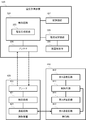
- the route instruction device 100 determines a moving route based on the identification information and the time information stored in the temperature information storage unit 202 in association with the temperature information.
- the route instruction device 100 transmits route information indicating the determined movement route to the control unit 440.
- the route instruction device 100 determines a plurality of candidate routes that are movement route candidates based on the area designation information that designates the storage area 310 of the storage location of the article 330 or the storage source of the article 330. Then, the route instruction device 100 determines a candidate route that passes through the storage area 310 where the time at which the temperature information was collected is the oldest, from the plurality of determined candidate routes, as the movement route.
- the control unit 101 controls the entire operation of the route instruction device 100.
- the function of the control unit 101 is realized, for example, by the processor 11 executing a program stored in the flash memory 12.
- the instruction receiving unit 102 receives various instructions from a user or an external device (not shown). For example, the instruction receiving unit 102 receives an instruction to transport the article 330 from the user.
- the function of the instruction receiving unit 102 is realized by, for example, the function of the touch screen 13.
- the function of the instruction receiving unit 102 is realized by, for example, the function of the first communication interface 14.
- the first communication unit 103 communicates with the control unit 440 according to an instruction from the control unit 101.
- the function of the first communication unit 103 is realized by, for example, cooperation between the processor 11 and the first communication interface 14.
- the second communication unit 104 communicates with the temperature information collection device 200 according to an instruction from the control unit 101.
- the function of the second communication unit 104 is realized, for example, by the processor 11 and the second communication interface 15 working together.
- the temperature information collecting device 200 collects the temperature information and the identification information acquired by the reading device 420.
- the temperature information collection device 200 functionally includes a control unit 201, a temperature information storage unit 202, and a communication unit 203.
- the temperature information storage unit corresponds to, for example, the temperature information storage unit 202.
- the control unit 201 controls the overall operation of the temperature information collection device 200.
- the function of the control unit 201 is realized, for example, by the processor 21 executing a program stored in the flash memory 22.
- the temperature information storage unit 202 stores the temperature information, the identification information, and the time information indicating the time at which the temperature information and the identification information were collected in association with each other.
- the function of the temperature information storage unit 202 is realized by, for example, cooperation between the processor 21 and the flash memory 22.
- the communication unit 203 communicates with the route instruction device 100 under the control of the control unit 201.
- the function of the communication unit 203 is realized by, for example, cooperation between the processor 21 and the communication interface 24.
- the temperature measurement device 320 is installed in each of the plurality of storage areas 310.
- the temperature measuring device 320 measures the temperature of the storage area 310 where the temperature measuring device 320 is installed.
- the temperature measurement device 320 includes a control circuit 324, an antenna 326, a storage circuit 327, a resistance temperature detector 328, and a current measurement circuit 329.
- the control circuit 324 controls the entire operation of the temperature measuring device 320.
- the control circuit 324 includes a power supply generation circuit 325.
- the power supply generation circuit 325 generates a power supply necessary for the operation of the temperature measurement device 320 from the first radio wave received by the antenna 326.
- the antenna 326 receives the first radio wave emitted from the reader 420. Further, the antenna 326 emits a second radio wave including temperature information and identification information according to the control of the control circuit 324.
- the storage circuit 327 stores the identification information.
- the resistance temperature detector 328 is a sensor that measures the temperature by measuring the electric resistance of a metal or metal oxide by using the characteristic that the electric resistance changes with the temperature. A current according to the voltage applied by the current measuring circuit 329 and the ambient temperature flows through the resistance temperature detector 328.
- the resistance temperature detector 328 can measure the resistance instantaneously.
- the resistance temperature detector 328 is, for example, a platinum resistance temperature detector.
- the operating temperature of the platinum resistance thermometer is, for example, ⁇ 200 ° C. to 100 ° C. As described above, the resistance temperature detector 328 can operate even at a low temperature.
- the temperature measurement accuracy using a platinum resistance temperature detector is higher than the temperature measurement accuracy using an infrared temperature sensor, for example.
- the current measurement circuit 329 applies a predetermined voltage to the resistance bulb 328 and measures the current flowing through the resistance bulb 328.
- the current measuring circuit 329 measures the temperature of the air around the temperature measuring device 320 from the measured current value.
- the temperature measurement device 320 functionally includes a temperature sensor 321, an identification information storage unit 322, and a radio wave transmission / reception unit 323.
- the identification information storage unit corresponds to, for example, the identification information storage unit 322.
- the radio transmission / reception unit corresponds to, for example, the radio transmission / reception unit 323.
- the temperature sensor 321 measures the temperature of the storage area 310.
- the function of the temperature sensor 321 is realized, for example, by cooperation of the resistance temperature detector 328 and the current measurement circuit 329.
- the identification information storage unit 322 stores identification information for identifying the storage area 310.
- the function of the identification information storage unit 322 is realized by, for example, the function of the storage circuit 327.
- the radio transmission / reception unit 323 radiates the second radio wave using the power generated from the first radio wave in response to receiving the first radio wave.
- the second radio wave includes temperature information indicating the temperature measured by the temperature sensor 321 and the identification information stored in the identification information storage unit 322.
- the transporter 410 loads the articles 330.
- the reading device 420 is installed on the transporter 410.
- the reading device 420 includes a control circuit 421, an antenna 422, and a communication circuit 423.
- the control circuit 421 controls the entire operation of the reading device 420.
- the antenna 422 radiates the first radio wave under the control of the control circuit 421. Further, the antenna 422 receives the second radio wave transmitted by the antenna 326.
- the communication circuit 423 communicates with the control unit 440 according to the control of the control circuit 421.
- the reader 420 emits the first radio wave and receives the second radio wave transmitted by the temperature measurement device 320 closest to the portable device 410 among the plurality of temperature measurement devices 320 installed in the plurality of storage areas 310.
- the reading device 420 acquires the temperature information and the identification information included in the second radio wave. Note that the reading device 420 may receive the second radio waves transmitted by the plurality of temperature measuring devices 320 close to the transporter 410.
- the moving unit 430 moves the transporter 410 according to the control signal.
- the moving unit 430 functionally includes a first moving unit 433 and a second moving unit 434.
- the first moving unit corresponds to, for example, the first moving unit 433.
- the second moving unit corresponds to, for example, the second moving unit 434.
- the first direction is, for example, a vertical direction.
- the second direction is, for example, a left-right direction.
- the moving unit 430 can also move the transporter 410 in the front-back direction orthogonal to the up-down direction and the left-right direction.
- the first moving section 433 moves the transporter 410 in the first direction along the first moving rail extending in the first direction.
- the first moving rail is, for example, a vertical moving rail 451.
- the second moving unit 434 moves the transporter 410 in the second direction along the second moving rail extending in the second direction.
- the second moving rail is, for example, the left / right moving rail 452.
- the control unit 440 generates a control signal based on route information indicating a moving route of the transporter 410. Control unit 440 controls moving unit 430 according to the generated control signal.
- the control unit 440 functionally includes a control circuit 441, a first communication circuit 442, a second communication circuit 443, and a third communication circuit 444.
- the control circuit 441 controls the entire operation of the control unit 440.
- the first communication circuit 442 communicates with the route instruction device 100 under the control of the control circuit 441.
- the second communication circuit 443 communicates with the reading device 420 under the control of the control circuit 441.
- the third communication circuit 444 communicates with the moving unit 430 according to the control of the control circuit 441.
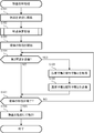
- the temperature measurement processing executed by the route instruction device 100 is included in the article storage processing.
- the temperature measurement method executed by the route instruction device 100 is realized by executing a temperature measurement process.
- the route instruction device 100 starts executing the article storage process in response to, for example, receiving a storage instruction of the article 330 from the user via the touch screen 13.
- the processor 11 loads the articles 330 on the transporter 410 (Step S101).
- the processor 11 instructs the control unit 440 to load the articles 330 on the transporter 410 via the first communication interface 14, for example.
- control unit 440 transmits a control signal according to this instruction to moving unit 430.
- the moving unit 430 loads the articles 330 on the transporter 410 according to the control signal.
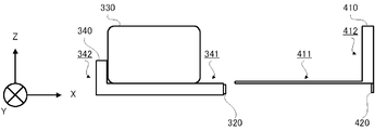
- FIG. 7A shows a side view of the article 330, the shelf 340, and the carrier 410 before the article 330 is taken out of the rack shelf 300 by the carrier 410.
- a view of the object viewed from the negative direction of the Y axis is called a side view of the object.
- the shelf 340 is a plate on which the articles 330 are stacked on the rack shelf 300.
- the shelf board 340 includes a stacking section 341 and a side wall section 342.
- the loading section 341 is a plate-shaped portion having a loading surface (not shown) on which the articles 330 are loaded.
- the thickness direction of the stacking unit 341 is the Z-axis direction.
- the side wall portion 342 is a plate-like portion that restricts the movement of the article 330 in the Y-axis direction.
- the thickness direction of the side wall portion 342 is the X-axis direction.
- the temperature measuring device 320 is installed at an end on the near side of the loading unit 341, that is, at an end of the loading unit 341 in the positive direction in the X-axis direction.
- the temperature measuring device 320 is fixed to the front end of the stacking portion 341 by a fixing member such as a double-sided tape or a screw.
- the outer shape of the temperature measuring device 320 is basically the outer shape of the antenna 326 and is in a sheet shape.
- the thickness direction of the temperature measuring device 320 is the X-axis direction.
- the radiation surface (not shown) of the antenna 326 provided in the temperature measuring device 320 is orthogonal to the X-axis direction.
- the transporter 410 includes a loading section 411 and a side wall section 412.
- the loading section 411 is a plate-shaped portion having a loading surface (not shown) on which the articles 330 are loaded.
- the thickness direction of the stacking section 411 is the Z-axis direction.
- the side wall portion 412 is a plate-like portion that restricts the movement of the article 330 in the X-axis direction.
- the thickness direction of the side wall part 412 is the X-axis direction.
- the reading device 420 is installed at the bottom end of the side wall 412, that is, at the end of the side wall 412 in the negative direction in the Z-axis direction.
- the reading device 420 is fixed to the bottom end of the side wall 412 by a fixing member such as a double-sided tape or a screw.
- the outer shape of the reading device 420 is basically the outer shape of the antenna 422, and is in a sheet shape.
- the thickness direction of the reading device 420 is the X-axis direction.
- the radiation surface (not shown) of the antenna 422 included in the reader 420 is orthogonal to the X-axis direction.
- the radiation surface (not shown) of the antenna 326 provided in the temperature measuring device 320 and the radiation surface (not shown) of the antenna 422 provided in the reading device 420 face each other, and the temperature measuring device 320 and the reading device
- the reading device 420 can acquire the temperature information and the identification information from the temperature measuring device 320.
- FIG. 7A in a state immediately before the article 330 is taken out from the rack shelf 300, the radiation surface (not shown) of the antenna 326 provided in the temperature measuring device 320 and the radiation surface of the antenna 422 provided in the reading device 420 are provided.
- the planes (not shown) are parallel and face each other.
- the reading device 420 can acquire the temperature information and the identification information from the temperature measuring device 320.
- FIG. 7B is a side view of the article 330, the shelf 340, and the transporter 410 immediately after the articles 330 are loaded on the transporter 410.
- FIG. 7D is a front view of the article 330, the shelf 340, and the transporter 410 immediately after the articles 330 are loaded on the transporter 410.
- a view of the object viewed from the positive direction of the X axis is referred to as a front view of the object.
- the radiation surface (not shown) of the antenna 326 provided in the temperature measuring device 320 and the reading device 420 are provided.
- the radiation surface (not shown) of the antenna 422 is parallel and faces each other.
- the distance between the temperature measuring device 320 and the reading device 420 is several centimeters or less, or several tens centimeters or less. Therefore, in a state immediately before the article 330 is taken out from the rack shelf 300, the reading device 420 can reliably acquire the temperature information and the identification information from the temperature measuring device 320.
- FIG. 7C shows a side view of the article 330, the shelf 340, and the transporter 410 immediately after the article 330 is taken out of the rack shelf 300.
- the reading device 420 acquires the temperature information and the identification information from the temperature measuring device 320, similarly to the state immediately before the article 330 is taken out of the rack shelf 300. be able to.
- the radiation surface (not shown) of the antenna 326 provided in the temperature measurement device 320 and the radiation surface (not shown) of the antenna 422 provided in the reading device 420 are provided. ) Are parallel and opposing each other is maintained. In this state, the distance between the temperature measuring device 320 and the reading device 420 is several meters or less. Therefore, when the transporter 410 moves in the Y-axis direction or the Z-axis direction, the reading device 420 can acquire the temperature information and the identification information from the temperature measuring device 320.
- the reading device 420 identifies the temperature information from the temperature measurement device 320. Information can be reliably obtained.
- the reading device 420 Temperature information and identification information can be obtained.
- the processor 11 executes a route determination process (step S102). The route determination processing will be described in detail with reference to FIG.
- the processor 11 determines a plurality of candidate routes (Step S201). For example, as shown in FIG. 9, it is assumed that the source of the article 330 is the storage area 310 indicated by P1, and the destination of the article 330 is the storage area 310 indicated by P9. In this case, for example, four candidate routes of R1, R2, R3, and R4 are determined.
- R1 is a path that passes through the storage area 310 in the order of P1, P2, P3, P6, and P9.
- R2 is a path that passes through the storage area 310 in the order of P1, P4, P7, P8, and P9.
- R3 is a path that passes through the storage area 310 in the order of P1, P4, P5, P8, and P9.
- R4 is a path that passes through the storage area 310 in the order of P1, P5, and P9.
- step S202 When the processing of step S201 is completed, the processor 11 selects one candidate path (step S202). For example, the processor 11 selects R1 from four candidate routes of R1, R2, R3, and R4.
- step S203 the processor 11 specifies all the storage areas 310 passing through the selected one candidate route (step S203). For example, the processor 11 specifies P1, P2, P3, P6, and P9 for the selected R1.
- step S204 the processor 11 determines whether there is any unselected candidate route.
- step S204 determines that there is an unselected candidate route (step S204: YES)
- the process returns to step S202, and selects one candidate route from the unselected candidate routes.
- step S204: NO the processor 11 sorts all the specified storage areas 310 in order of the temperature information acquisition time (step S205).
- step S205 the processor 11 specifies the storage area 310 where the acquisition time of the temperature information is the oldest (step S206). Upon completing the process in step S206, the processor 11 determines a candidate route that passes through the specified storage area 310 as a movement route (step S207).
- the processor 11 specifies P8 as the storage area 310 with the oldest acquisition time.
- P8 the storage area 310 with the oldest acquisition time.
- R2 which is a route that passes through P7 whose temperature information acquisition time is the second oldest after P8, is specified. Then, R2 is determined as the movement route.
- a route that passes P2 whose temperature information acquisition time is the oldest after P7 is set as a travel route. It is determined.
- the processor 11 completes the route determination process.
- the processor 11 When the processor 11 completes the route determination processing in step S102, the processor 11 starts moving the transporter 410 (step S103). For example, the processor 11 transmits, to the control unit 440, route information indicating a movement route and start instruction information for instructing start of movement.
- control unit 440 in response to receiving the route information and the start instruction information from route instruction device 100, control unit 440 starts moving portable device 410. Specifically, the control unit 440 starts a process of controlling the up-down moving unit 431 and the left-right moving unit 432 with a control signal according to the route information.
- control unit 440 causes reading device 420 to start the process of emitting the first radio wave.
- step S104 determines whether or not the second radio wave has been received. For example, the processor 11 determines whether or not notification information notifying that the second radio wave has been received from the control unit 440 has been received by the first communication interface 14.
- step S104 acquires temperature information and identification information (step S105). For example, the processor 11 transmits request information for requesting transmission of the temperature information and the identification information to the control unit 440.
- control unit 440 transmits the temperature information and the identification information included in the second radio wave to route instruction device 100.
- step S106 the processor 11 transmits the temperature information and the identification information (step S106). That is, the processor 11 transmits the temperature information and the identification information to the temperature information collection device 200 via the second communication interface 15.
- the temperature information collection device 200 stores the temperature information and the identification information received from the route instruction device 100 in association with the time information indicating the acquisition time of the temperature information and the identification information.
- step S104 determines whether the movement of the transporter 410 has been completed (step S104). S107). For example, the processor 11 determines whether or not the notification information for notifying that the movement of the portable device 410 has been completed is received by the first communication interface 14 from the control unit 440. When determining that the movement of the transporter 410 has not been completed (step S107: NO), the processor 11 returns the process to step S104.
- step S108 when the processor 11 determines that the movement of the transporter 410 has been completed (step S107: YES), the processor 11 stores the article 330 on the designated shelf (step S108).
- the processor 11 instructs the control unit 440 to cause the transporter 410 to store the article 330 on the designated shelf via the first communication interface 14, for example.
- control unit 440 transmits a control signal according to this instruction to moving unit 430.
- the moving unit 430 causes the transporter 410 to store the article 330 on the designated shelf according to the control signal.
- the processor 11 completes the article storing process.
- the temperature measuring device 320 is installed in each of the plurality of storage areas 310, and the reading device 420 is installed on the transporter 410 on which the articles 330 are loaded. Therefore, the temperatures of the plurality of storage areas 310 provided in the rack shelf 300 can be efficiently measured in a short time.
- the temperature measuring device 320 includes the temperature measuring resistor 328, and the temperature information is transmitted from the temperature measuring device 320 to the reading device 420 by wireless communication.
- the time required for temperature measurement by the resistance temperature detector 328 is short, and the time for transmitting temperature information by wireless communication is also short. Therefore, the temperature of the storage area 310 can be measured instantaneously.
- the temperature measuring device 320 includes a passive type RFID tag in which the temperature sensor 321 is incorporated, and operates with the power of the first radio wave received from the reading device 420. Therefore, there is no need to provide a power supply for the temperature measuring device 320, and cost reduction can be expected.
- the moving route is determined based on the identification information and the time information stored in association with the temperature information. More specifically, of the plurality of candidate routes, the candidate route that passes through the storage area 310 where the time when the temperature information is collected is the oldest is determined as the movement route. Therefore, it is possible to suppress the occurrence of the storage area 310 in which the temperature information is not obtained for a long time.
- the route instruction device 100 determines a plurality of candidate routes that are candidates for the movement route based on the area designation information that designates the storage area 310 of the storage location of the article 330 or the storage source of the article 330. Then, the route instruction device 100 most frequently stores the storage area 310 in which the time difference between the time when the temperature information is collected and the current time is equal to or greater than a predetermined threshold (for example, one week) among the plurality of determined candidate routes.
- the candidate area to be passed is determined as a movement route. That is, the route instruction device 100 adopts a candidate route that includes many storage areas 310 whose temperature information acquisition times are old as the moving route.
- R1 is a candidate route that does not pass through the storage area 310 for which temperature information has not been acquired for one week or more.
- R2 is a candidate route that passes through one storage area 310 for which temperature information has not been acquired for one week or more.
- R3 is a candidate route that passes through two storage areas 310 for which temperature information has not been acquired for one week or more.
- R4 is a candidate route that passes through one storage area 310 for which temperature information has not been acquired for one week or more. Therefore, it is preferable that R3 is determined as the movement route.
- the candidate region that most frequently passes through the storage region 310 in which the time difference between the time when the temperature information is collected and the current time is equal to or greater than a predetermined threshold is determined as the movement route. You. Therefore, it is possible to collect temperature information about many storage areas 310 whose acquisition times of temperature information are relatively old by one movement.
- This embodiment is effective when the traveling time of the transporter 410 in the second direction is sufficiently longer than the traveling time of the transporter 410 in the first direction.
- the moving distance of the transport device 410 in the second direction is the same as that in the first direction. This is effective when the distance is sufficiently long with respect to the moving distance in.
- the moving speed of the transport device 410 in the second direction is the first direction of the transport device 410. This is effective when the moving speed is sufficiently slow.
- the path instruction device 100 includes a plurality of routes including a route in which the traveling time of the transport device 410 in the second direction is longer than the traveling time of the transport device 410 in the first direction, and the route returns in the first direction but does not return in the second direction. Is determined.
- the moving speed of the transporter 410 in the second direction is equal to the speed of the transporter 410.
- An example is shown in which the moving speed in one direction is sufficiently slow. Note that the first direction is the Z-axis direction and the second direction is the Y-axis direction.
- FIG. 12 shows an example in which three candidate routes, R11, R12, and R13, have been determined as routes from P1 to P9.
- R13 is a path passing in the order of P1, P4, P7, P8, P5, P6, and P9.
- R13 is a path that returns in the first direction and does not return in the second direction.
- the time when the transporter 410 moves from P1 to P9 is the shortest time, even when R13 is determined as the movement route, as in the case where R11 or R12 is determined as the movement route.
- the processor 11 determines whether or not there is an article storage instruction (step S301). For example, the processor 11 determines whether an operation corresponding to the article storage instruction has been performed on the touch screen 13. When determining that there is an article storage instruction (step S301: YES), the processor 11 executes an article storage process (step S302). This article storage processing is basically the same as the article storage processing shown in FIG.
- step S303 determines whether there is an article removal instruction. For example, the processor 11 determines whether an operation corresponding to the article removal instruction has been performed on the touch screen 13.
- step S304 executes an article removal process. This article removal processing is basically the same as the article storage processing shown in FIG. 6 except that the storage of the article 330 and the removal of the article 330 are different.
- step S303: NO If it is determined that there is no article removal instruction (step S303: NO), or if the process of step S304 is completed, the processor 11 determines whether there is a storage area 310 for which temperature information has not been acquired for one week or more. (Step S305). When determining that there is no storage area 310 for which temperature information has not been acquired for one week or more (step S305: NO), the processor 11 returns the process to step S301. On the other hand, if the processor 11 determines that there is a storage area 310 for which temperature information has not been acquired for one week or more (step S305: YES), the processor 11 executes a route determination process (step S306). In this route determination process, a route that passes through the first storage area, which is the storage area 310 for which temperature information has not been acquired for one week or more, is determined as a movement path.
- step S306 When the processing of step S306 is completed, the processor 11 starts moving the transporter 410 (step S307). Upon completing the process in step S307, the processor 11 determines whether the second radio wave has been received (step S308). When determining that the second radio wave has been received (step S308: YES), the processor 11 acquires the temperature information and the identification information (step S309), and transmits the temperature information and the identification information (step S310).
- step S308 When determining that the second radio wave has not been received (step S308: NO), or when completing the process of step S310, the processor 11 determines whether the movement of the transporter 410 has been completed (step S308). S311). When determining that the movement of the transporter 410 has not been completed (step S311: NO), the processor 11 returns the process to step S308. On the other hand, when the processor 11 determines that the movement of the transporter 410 has been completed (step S311: YES), the process returns to step S301.
- the storage area 310 it is possible to prevent the storage area 310 from not acquiring temperature information for a long period of time.
- the route instruction device 100 and the temperature information collection device 200 are separate devices.
- the route instruction device 100 may be incorporated in the temperature information collection device 200, or the temperature information collection device 200 may be incorporated in the route instruction device 100. Further, the route instruction device 100 or the temperature information collection device 200 may be incorporated in the control unit 440.
- temperature information may be acquired when the article 330 is taken out.
- the temperature information of the storage area 310 on the moving route of the portable device 410 can be obtained. Further, as described in the fourth embodiment, the temperature information may be obtained without moving the article 330.
- the temperature measurement device 320 measures the temperature by measuring the current.
- the example in which the temperature measuring device 320 measures the temperature by measuring the voltage has been described.
- the temperature measuring device 320 applies a constant voltage to the resistance bulb 328 instead of the current measurement circuit 329 that measures a current flowing through the resistance bulb 328 by applying a constant voltage to the resistance bulb 328.
- a voltage measuring circuit (not shown) for measuring a voltage applied to the resistance bulb 328.
- the temperature measuring device 320 is installed at the front end of the shelf 340 and the reading device 420 is installed at the bottom of the transport device 410 on the front side.
- the position where the temperature measuring device 320 and the reading device 420 are installed is not limited to this example.
- the example in which the thickness direction of the temperature measurement device 320 and the thickness direction of the reading device 420 are the X-axis direction, which is the front-back direction has been described.
- the angle at which the temperature measuring device 320 and the reading device 420 are installed is not limited to this example.
- the temperature measuring device 320 and the reading device 420 be installed at a position and an angle at which the temperature measuring device 320 and the reading device 420 can communicate with each other. That is, it is preferable that the distance between the temperature measuring device 320 and the reading device 420 is as short as possible, and that the radiation surface of the antenna 326 included in the temperature measuring device 320 and the radiation surface of the antenna 422 included in the reading device 420 are as parallel as possible. . In addition, it is desirable that the temperature measuring device 320 and the reading device 420 be installed at a position and an angle that do not break when the article 330 is transported by the transporter 410.
- the personal computer or the like can also function as the route instruction device 100 according to the present invention.
- the distribution method of such a program is arbitrary.
- the program is stored and distributed on a computer-readable recording medium such as a CD-ROM (Compact Disk Read-Only Memory), a DVD (Digital Versatile Disk), and a memory card.
- a computer-readable recording medium such as a CD-ROM (Compact Disk Read-Only Memory), a DVD (Digital Versatile Disk), and a memory card.
- a communication network such as the Internet.
- the present invention is applicable to an automatic warehouse having a rack shelf and a transport device.
Landscapes
- Engineering & Computer Science (AREA)
- Mechanical Engineering (AREA)
- Warehouses Or Storage Devices (AREA)
Abstract
温度計測装置(320)は、ラック棚が有する複数の格納領域のそれぞれに設置され、格納領域の温度を計測する温度センサ(321)と、格納領域を識別するための識別情報を記憶する識別情報記憶部(322)と、第1電波を受信したことに応答して第1電波から生成した電力を用いて、温度情報と識別情報とを含む第2電波を送信する電波送受信部(323)と、を備える。読取装置(420)は、搬機(410)に設置され、第1電波を送信し、複数の格納領域に設置された複数の温度計測装置(320)のうち搬機(410)に最も近い温度計測装置(320)により送信された第2電波を受信し、第2電波に含まれる温度情報と識別情報とを取得する。温度情報収集装置(200)は、読取装置(420)により取得された温度情報と識別情報とを収集する。
Description
本発明は、温度計測システム、温度計測方法、及び、プログラムに関する。
現在、複数の格納領域を有するラック棚と、搬機を用いて物品を所望の格納領域に運搬する運搬装置と、を備える自動倉庫が知られている。このような自動倉庫において、複数の格納領域の温度を管理する種々の技術が知られている。例えば、特許文献1には、運搬装置であるスタッカークレーンが備える搬機に温度センサを設け、この温度センサで格納物の温度を測定する技術が知られている。
特許文献1に記載された技術では、温度測定を必要とする格納物の位置に搬機を移動させ、搬機に設けられた温度センサを用いて格納物の温度を非接触で測定する。測定された温度を示す測定温度データは、スタッカークレーンが備える制御部を経由して、地上に設置されたデータ集積装置に伝送される。
しかしながら、特許文献1に記載された技術では、格納物の温度を測定する温度センサが搬機に設けられる。このため、温度センサの測定値を安定させるためには、格納物の前で搬機を停止させる必要があり、格納物の温度を短時間で効率良く計測することができなかった。このため、ラック棚が備える複数の格納領域の温度を短時間で効率良く計測する技術が望まれている。
本発明は、上記問題に鑑みてなされたものであり、ラック棚が備える複数の格納領域の温度を短時間で効率良く計測する温度計測システム、温度計測方法、及び、プログラムを提供することを目的とする。
上記目的を達成するために、本発明に係る温度計測システムは、
複数の格納領域を有するラック棚と、前記複数の格納領域のいずれかに格納される物品を積載する搬機と制御信号に従って前記搬機を移動させる移動手段とを備える運搬装置と、を備える自動倉庫において、前記複数の格納領域の温度を計測する温度計測システムであって、
前記複数の格納領域のそれぞれに設置され、前記格納領域の温度を計測する温度センサと、前記格納領域を識別するための識別情報を記憶する識別情報記憶手段と、第1電波を受信したことに応答して前記第1電波から生成した電力を用いて、前記温度センサにより計測された前記温度を示す温度情報と前記識別情報記憶手段に記憶された前記識別情報とを含む第2電波を送信する電波送受信手段と、を備える温度計測装置と、
前記搬機に設置され、前記第1電波を送信し、前記複数の格納領域に設置された複数の前記温度計測装置のうち前記搬機に最も近い前記温度計測装置により送信された前記第2電波を受信し、前記第2電波に含まれる前記温度情報と前記識別情報とを取得する読取装置と、
前記読取装置により取得された前記温度情報と前記識別情報とを収集する温度情報収集装置と、を備える。
複数の格納領域を有するラック棚と、前記複数の格納領域のいずれかに格納される物品を積載する搬機と制御信号に従って前記搬機を移動させる移動手段とを備える運搬装置と、を備える自動倉庫において、前記複数の格納領域の温度を計測する温度計測システムであって、
前記複数の格納領域のそれぞれに設置され、前記格納領域の温度を計測する温度センサと、前記格納領域を識別するための識別情報を記憶する識別情報記憶手段と、第1電波を受信したことに応答して前記第1電波から生成した電力を用いて、前記温度センサにより計測された前記温度を示す温度情報と前記識別情報記憶手段に記憶された前記識別情報とを含む第2電波を送信する電波送受信手段と、を備える温度計測装置と、
前記搬機に設置され、前記第1電波を送信し、前記複数の格納領域に設置された複数の前記温度計測装置のうち前記搬機に最も近い前記温度計測装置により送信された前記第2電波を受信し、前記第2電波に含まれる前記温度情報と前記識別情報とを取得する読取装置と、
前記読取装置により取得された前記温度情報と前記識別情報とを収集する温度情報収集装置と、を備える。
本発明では、格納領域の温度を計測する温度センサと、格納領域を識別するための識別情報を記憶する識別情報記憶手段と、第1電波を受信したことに応答して第1電波から生成した電力を用いて、温度情報と識別情報とを含む第2電波を送信する電波送受信手段と、を備える温度計測装置が、複数の格納領域のそれぞれに設置され、第1電波を送信し、搬機に最も近い温度計測装置により送信された第2電波を受信し、第2電波に含まれる温度情報と識別情報とを取得する読取装置が、搬機に設置される。従って、本発明によれば、ラック棚が備える複数の格納領域の温度を短時間で効率良く計測することができる。
(実施形態1)
まず、図1を参照して、本発明の実施形態1に係る自動倉庫2000の構成について説明する。なお、自動倉庫2000には、図4に示す温度計測システム1000が組み込まれる。自動倉庫2000は、物品の管理がコンピュータ制御により自動化された倉庫である。自動倉庫2000は、例えば、低温で保管すべき物品を自動で管理する冷凍倉庫である。
まず、図1を参照して、本発明の実施形態1に係る自動倉庫2000の構成について説明する。なお、自動倉庫2000には、図4に示す温度計測システム1000が組み込まれる。自動倉庫2000は、物品の管理がコンピュータ制御により自動化された倉庫である。自動倉庫2000は、例えば、低温で保管すべき物品を自動で管理する冷凍倉庫である。
本実施形態では、自動倉庫2000は、主に、物品を所望の場所に運搬する運搬機能と、物品が配置された領域の温度を計測する温度計測機能とを有する。そして、自動倉庫2000は、物品が配置された領域の温度を効率的に計測するために、主に、物品の運搬時にこの領域の温度を計測する。自動倉庫2000は、例えば、冷凍機(図示せず)により物品を低温に維持する冷凍機能を有するが、冷凍機能については説明を省略する。自動倉庫2000は、経路指示装置100と、温度情報収集装置200と、ラック棚300と、運搬装置400と、を備える。
経路指示装置100は、運搬装置400が備える搬機410の移動経路を決定し、決定した移動経路を示す経路情報を、運搬装置400が備える制御部440に送信する。また、経路指示装置100は、制御部440から温度情報と識別情報とを受信し、受信した温度情報と識別情報とを温度情報収集装置200に送信する。温度情報は、ラック棚300が備える複数の格納領域310のうち1つの格納領域310の温度を計測することにより得られた温度を示す情報である。識別情報は、温度が計測された格納領域310を識別するための情報である。経路指示装置100は、長期間に亘って温度が計測されない格納領域310がなるべく生じないように、搬機410の移動経路を決定する。
以下、図2を参照して、経路指示装置100の構成について説明する。図2に示すように、経路指示装置100は、プロセッサ11と、フラッシュメモリ12と、タッチスクリーン13と、第1通信インターフェース14と、第2通信インターフェース15と、を備える。プロセッサ11は、経路指示装置100の全体の動作を制御する。プロセッサ11は、例えば、ROM(Read Only Memory)、RAM(Random Access Memory)、RTC(Real Time Clock)などを内蔵したCPU(Central Processing Unit)である。なお、CPUは、例えば、ROMに格納されている基本プログラムに従って動作し、RAMをワークエリアとして使用する。
フラッシュメモリ12は、各種の情報を記憶する不揮発性メモリである。フラッシュメモリ12は、例えば、プロセッサ11が実行するプログラムを記憶する。タッチスクリーン13は、ユーザによりなされた操作を検知し、検知の結果を示す信号をプロセッサ11に供給する。また、タッチスクリーン13は、プロセッサ11による制御に従って、情報を表示する。
第1通信インターフェース14は、経路指示装置100を制御部440と通信可能にするための通信インターフェースである。第1通信インターフェース14は、例えば、無線LAN(Local Area Network)、Wi-Fi、又は、Bluetooth(登録商標)などの無線通信用の通信インターフェースであってもよいし、USB(Universal Serial Bus)又はIEEE1394などの有線通信用の通信インターフェースであってもよい。第2通信インターフェース15は、経路指示装置100を温度情報収集装置200と通信可能にするための通信インターフェースである。第2通信インターフェース15は、上述した各種の無線通信用の通信インターフェースであってもよいし、上述した各種の有線通信用の通信インターフェースであってもよい。
温度情報収集装置200は、ラック棚300が備える複数の格納領域310のそれぞれの温度情報を収集する。温度情報収集装置200は、例えば、経路指示装置100を介して、制御部440から、温度情報と識別情報とを受信する。温度情報収集装置200は、受信した温度情報と識別情報とを、温度情報と識別情報とを収集した時刻を示す時刻情報と対応付けて記憶する。なお、温度情報と識別情報とを収集した時刻は、基本的に、温度情報と識別情報とを受信した時刻である。
以下、図3を参照して、温度情報収集装置200の構成について説明する。図3に示すように、温度情報収集装置200は、プロセッサ21と、フラッシュメモリ22と、タッチスクリーン23と、通信インターフェース24と、を備える。プロセッサ21は、温度情報収集装置200の全体の動作を制御する。プロセッサ21は、例えば、ROM、RAM、RTCなどを内蔵したCPUである。なお、CPUは、例えば、ROMに格納されている基本プログラムに従って動作し、RAMをワークエリアとして使用する。
フラッシュメモリ22は、各種の情報を記憶する不揮発性メモリである。フラッシュメモリ22は、例えば、プロセッサ21が実行するプログラムを記憶する。タッチスクリーン23は、ユーザによりなされた操作を検知し、検知の結果を示す信号をプロセッサ21に供給する。また、タッチスクリーン23は、プロセッサ21による制御に従って、情報を表示する。
通信インターフェース24は、温度情報収集装置200を経路指示装置100と通信可能にするための通信インターフェースである。通信インターフェース24は、上述した各種の無線通信用の通信インターフェースであってもよいし、上述した各種の有線通信用の通信インターフェースであってもよい。
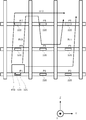
ラック棚300は、管理対象である物品330を格納するための複数の格納領域310を備える棚である。複数の格納領域310は、Z軸方向とZ軸方向に直交するY軸方向とに2次元に並んで配置される。Z軸方向は、例えば、鉛直方向である。なお、図1において、X軸方向は、Z軸方向とY軸方向とに直交する方向である。本実施形態では、理解を容易にするため、複数の格納領域310は、Z軸方向に3個、Y軸方向に4個並ぶ12個の格納領域310であり、同一の形状及び同一の大きさであるものとする。ただし、複数の格納領域310は、Z軸方向に2個以下又は4個以上、Y軸方向に3個以下又は5個以上並んでいてもよく、異なる形状又は異なる大きさであってもよい。
温度計測装置320は、複数の格納領域310のそれぞれに設置される。温度計測装置320は、温度計測装置320が設置された格納領域310の温度を計測する。温度計測装置320は、例えば、パッシブ型のRFID(Radio Frequency Identifier)タグに、温度センサが組み込まれた装置である。温度計測装置320は、非接触給電により動作する。つまり、温度計測装置320は、読取装置420から受信した第1電波に基づく電力により動作する。
温度計測装置320は、例えば、1つの格納領域310の下部に設けられた棚板の前面の中央に設置される。棚板の前面は、例えば、図1において、略板状の棚板が備える6つの面のうち、搬機410と対向する面である。温度計測装置320は、温度計測装置320が設置された格納領域310の内部の空気の温度、温度計測装置320が設置された格納領域310の近傍の空気の温度、又は、温度計測装置320が設置された格納領域310に格納された物品330の温度を測定可能な任意の位置に配置される。なお、温度計測装置320が設置された格納領域310の内部の空気の温度と、温度計測装置320が設置された格納領域310の近傍の空気の温度と、温度計測装置320が設置された格納領域310に格納された物品330の温度とは、実質的に等しいものとする。
物品330は、ラック棚300に格納される格納物である。物品330は、どのようなものであってもよい。本実施形態では、物品330は、低温で保存することが要求される物品であるものとする。1つの物品330は、1つの格納領域310に格納される。物品330は、格納領域310の下部に設けられた棚板に積載される。
運搬装置400は、物品330を運搬する装置である。運搬装置400は、例えば、スタッカークレーンである。運搬装置400は、例えば、ある格納領域310に格納された物品330を、他の格納領域310に格納する。あるいは、運搬装置400は、ある格納領域310に格納された物品330を、予め定められた基準位置まで運搬する。あるいは、運搬装置400は、予め定められた基準位置に配置された物品330を、所望の格納領域310に格納する。予め定められた基準位置は、例えば、ベルトコンベア(図示せず)上のいずれかの位置である。運搬装置400は、搬機410と、上下移動部431と、左右移動部432と、制御部440と、上下移動用レール451と、左右移動用レール452と、前後移動部(図示せず)と、を備える。
搬機410は、運搬対象の物品330を積載する。搬機410には、読取装置420が設置される。読取装置420は、第1電波を放射し、読取装置420の近くに配置された温度計測装置320から第2電波を受信する。第1電波は、温度計測装置320に電力を供給するための電波である。第2電波は、第1電波を受信した温度計測装置320が放射する電波であり、温度情報と識別情報とを含む電波である。読取装置420は、例えば、RFIDリーダライタである。
読取装置420は、温度計測装置320との間で電波の送受信がしやすい搬機410上の位置に設置される。例えば、読取装置420は、搬機410の手前側の下部に設置される。図1に示す例では、読取装置420は、搬機410のZ軸方向における両端のうちZ軸方向における座標が小さい方の端部であり、且つ、搬機410のX軸方向における両端のうちX軸における座標が大きい方の端部に配置される。
上下移動部431は、制御部440から受信した制御信号に従って、搬機410を上下移動用レール451に沿って上下方向に移動させる。図1に示す例では、上下方向は、Z軸方向である。上下移動部431は、例えば、モータ(図示せず)、プーリー(図示せず)、及び、電源回路(図示せず)を備える。左右移動部432は、制御部440から受信した制御信号に従って、搬機410を左右移動用レール452に沿って左右方向に移動させる。図1に示す例では、左右方向は、Y軸方向である。左右移動部432は、例えば、モータ(図示せず)、プーリー(図示せず)、及び、電源回路(図示せず)を備える。なお、前後移動部(図示せず)は、制御部440から受信した制御信号に従って、搬機410を前後方向に移動させる。図1に示す例では、前後方向は、X軸方向である。前後移動部(図示せず)は、例えば、モータ(図示せず)、プーリー(図示せず)、及び、電源回路(図示せず)を備える。
制御部440は、搬機410の移動経路を示す経路情報に基づいて制御信号を生成し、生成した制御信号に従って、上下移動部431と左右移動部432と前後移動部(図示せず)とを制御する。また、制御部440は、読取装置420から温度情報と識別情報とを受信し、受信した温度情報と識別情報とを経路指示装置100を介して温度情報収集装置200に送信する。
上下移動用レール451は、搬機410を上下方向に移動させるためのガイドとなるレールである。上下移動用レール451は、上下方向に延在する。左右移動用レール452は、搬機410を左右方向に移動させるためのガイドとなるレールである。左右移動用レール452は、左右方向に延在する。
次に、図4を参照して、温度計測システム1000の機能について説明する。図4に示すように、温度計測システム1000は、経路指示装置100と、温度情報収集装置200と、温度計測装置320と、搬機410と、移動部430と、制御部440と、を備える。移動手段は、例えば、移動部430に対応する。制御手段は、例えば、制御部440に対応する。
経路指示装置100は、温度情報記憶部202に温度情報と対応付けて記憶された識別情報と時刻情報とに基づいて移動経路を決定する。経路指示装置100は、決定した移動経路を示す経路情報を制御部440に送信する。経路指示装置100は、物品330の格納先又は物品330の格納元の格納領域310を指定する領域指定情報に基づいて、移動経路の候補である複数の候補経路を決定する。そして、経路指示装置100は、決定した複数の候補経路のうち温度情報が収集された時刻が最も古い格納領域310を通過する候補経路を、移動経路として決定する。経路指示装置100は、機能的には、制御部101と、指示受付部102と、第1通信部103と、第2通信部104と、を備える。経路決定手段は、例えば、制御部101に対応する。経路情報送信手段は、例えば、制御部101及び第1通信部103に対応する。
制御部101は、経路指示装置100の全体の動作を制御する。制御部101の機能は、例えば、プロセッサ11がフラッシュメモリ12に記憶されたプログラムを実行することにより実現される。指示受付部102は、ユーザ、又は、外部装置(図示せず)から、各種の指示を受け付ける。例えば、指示受付部102は、ユーザから、物品330の運搬指示を受け付ける。指示受付部102の機能は、例えば、タッチスクリーン13の機能により実現される。或いは、指示受付部102の機能は、例えば、第1通信インターフェース14の機能により実現される。
第1通信部103は、制御部101による指示に従って、制御部440と通信する。第1通信部103の機能は、例えば、プロセッサ11と第1通信インターフェース14とが協働することにより実現される。第2通信部104は、制御部101による指示に従って、温度情報収集装置200と通信する。第2通信部104の機能は、例えば、プロセッサ11と第2通信インターフェース15とが協働することにより実現される。
温度情報収集装置200は、読取装置420により取得された温度情報と識別情報とを収集する。温度情報収集装置200は、機能的には、制御部201と、温度情報記憶部202と、通信部203と、を備える。温度情報記憶手段は、例えば、温度情報記憶部202に対応する。制御部201は、温度情報収集装置200の全体の動作を制御する。制御部201の機能は、例えば、プロセッサ21がフラッシュメモリ22に記憶されたプログラムを実行することにより実現される。
温度情報記憶部202は、温度情報と、識別情報と、温度情報と識別情報とを収集した時刻を示す時刻情報と、を対応付けて記憶する。温度情報記憶部202の機能は、例えば、プロセッサ21とフラッシュメモリ22とが協働することにより実現される。通信部203は、制御部201による制御に従って、経路指示装置100と通信する。通信部203の機能は、例えば、プロセッサ21と通信インターフェース24とが協働することにより実現される。
温度計測装置320は、複数の格納領域310のそれぞれに設置される。温度計測装置320は、温度計測装置320が設置された格納領域310の温度を計測する。以下、図5を参照して、温度計測装置320の構成について説明する。温度計測装置320は、制御回路324と、アンテナ326と、記憶回路327と、測温抵抗体328と、電流測定回路329と、を備える。
制御回路324は、温度計測装置320の全体の動作を制御する。制御回路324は、電源生成回路325を備える。電源生成回路325は、アンテナ326が受信した第1電波から温度計測装置320が動作するために必要な電源を生成する。アンテナ326は、読取装置420から放射された第1電波を受信する。また、アンテナ326は、制御回路324による制御に従って、温度情報と識別情報とを含む第2電波を放射する。記憶回路327は、識別情報を記憶する。
測温抵抗体328は、金属又は金属酸化物が温度変化により電気抵抗値が変化する特性を利用し、その電気抵抗を測定することで温度を計測するセンサである。測温抵抗体328には、電流測定回路329により印加された電圧と、周囲の温度とに応じた電流が流れる。測温抵抗体328は、瞬時に抵抗を計測することができる。測温抵抗体328は、例えば、白金測温抵抗体である。白金測温抵抗体の動作温度は、例えば、-200℃から100℃である。このように、測温抵抗体328は、低温でも動作可能である。白金測温抵抗体を用いた温度計測精度は、例えば、赤外線温度センサを用いた温度計測精度よりも高い。
電流測定回路329は、測温抵抗体328に予め定められた電圧を印加し、測温抵抗体328に流れる電流を測定する。電流測定回路329は、測定した電流の値から、温度計測装置320の周囲の空気の温度を計測する。
温度計測装置320は、機能的には、温度センサ321と、識別情報記憶部322と、電波送受信部323と、を備える。識別情報記憶手段は、例えば、識別情報記憶部322に対応する。電波送受信手段は、例えば、電波送受信部323に対応する。
温度センサ321は、格納領域310の温度を計測する。温度センサ321の機能は、例えば、測温抵抗体328と電流測定回路329とが協働することにより実現される。識別情報記憶部322は、格納領域310を識別するための識別情報を記憶する。識別情報記憶部322の機能は、例えば、記憶回路327の機能により実現される。電波送受信部323は、第1電波を受信したことに応答して第1電波から生成した電力を用いて、第2電波を放射する。第2電波は、温度センサ321により計測された温度を示す温度情報と識別情報記憶部322に記憶された識別情報とを含む。
搬機410は、物品330を積載する。搬機410には、読取装置420が設置される。以下、図5を参照して、読取装置420の構成について説明する。読取装置420は、制御回路421と、アンテナ422と、通信回路423と、を備える。制御回路421は、読取装置420の全体の動作を制御する。アンテナ422は、制御回路421による制御に従って、第1電波を放射する。また、アンテナ422は、アンテナ326により送信された第2電波を受信する。通信回路423は、制御回路421による制御に従って、制御部440と通信する。
読取装置420は、第1電波を放射し、複数の格納領域310に設置された複数の温度計測装置320のうち搬機410に最も近い温度計測装置320により送信された第2電波を受信する。読取装置420は、第2電波に含まれる温度情報と識別情報とを取得する。なお、読取装置420は、搬機410に近い複数の温度計測装置320により送信された第2電波を受信してもよい。
移動部430は、制御信号に従って、搬機410を移動させる。移動部430は、機能的には、第1移動部433と、第2移動部434と、を備える。第1移動手段は、例えば、第1移動部433に対応する。第2移動手段は、例えば、第2移動部434に対応する。複数の格納領域310が、第1方向と第1方向に直交する第2方向とに並んでいるものとする。第1方向は、例えば、上下方向である。第2方向は、例えば、左右方向である。なお、移動部430は、上下方向と左右方向とに直交する前後方向に搬機410を移動させることもできる。
第1移動部433は、第1方向に延びる第1移動用レールに沿って搬機410を第1方向に移動させる。第1移動用レールは、例えば、上下移動用レール451である。第2移動部434は、第2方向に延びる第2移動用レールに沿って搬機410を第2方向に移動させる。第2移動用レールは、例えば、左右移動用レール452である。
制御部440は、搬機410の移動経路を示す経路情報に基づいて制御信号を生成する。制御部440は、生成した制御信号に従って移動部430を制御する。以下、図5を参照して、制御部440の構成について説明する。制御部440は、機能的には、制御回路441と、第1通信回路442と、第2通信回路443と、第3通信回路444と、を備える。
制御回路441は、制御部440の全体の動作を制御する。第1通信回路442は、制御回路441による制御に従って、経路指示装置100と通信する。第2通信回路443は、制御回路441による制御に従って、読取装置420と通信する。第3通信回路444は、制御回路441による制御に従って、移動部430と通信する。
次に、図6のフローチャートを参照して、経路指示装置100が実行する物品格納処理について説明する。なお、経路指示装置100が実行する温度計測処理は、物品格納処理に含まれる。また、経路指示装置100が実行する温度測定方法は、温度計測処理の実行により実現される。経路指示装置100は、例えば、タッチスクリーン13を介して、ユーザから、物品330の格納指示を受け付けたことに応答して、物品格納処理の実行を開始する。
まず、プロセッサ11は、物品330を搬機410に積載する(ステップS101)。プロセッサ11は、例えば、第1通信インターフェース14を介して、搬機410に物品330を積載させることを制御部440に指示する。一方、制御部440は、この指示に従った制御信号を、移動部430に送信する。移動部430は、この制御信号に従って、搬機410に物品330を積載させる。
以下、図7A、図7B、図7C、及び、図7Dを参照して、搬機410が物品330を積載する方法について説明する。図7Aに、物品330が搬機410によりラック棚300から取り出される前における、物品330、棚板340、及び、搬機410の側面図を示す。本実施形態では、Y軸の負の方向から対象物を見た図を対象物の側面図という。なお、棚板340は、ラック棚300において物品330が積載される板である。
棚板340は、積載部341と、側壁部342と、を備える。積載部341は、物品330が積載される積載面(図示せず)を備える板状の部分である。積載部341の厚み方向は、Z軸方向である。側壁部342は、物品330のY軸方向への移動を制限する板状の部分である。側壁部342の厚み方向は、X軸方向である。積載部341の手前側の端部、つまり、積載部341のX軸方向の正の方向における端部には、温度計測装置320が設置される。温度計測装置320は、例えば、両面テープ又はネジなどの固定用部材により、積載部341の手前側の端部に固定される。温度計測装置320の外形は、基本的に、アンテナ326の外形であり、シート状である。温度計測装置320の厚み方向は、X軸方向である。温度計測装置320が備えるアンテナ326の放射面(図示せず)は、X軸方向と直交する。
搬機410は、積載部411と、側壁部412と、を備える。積載部411は、物品330が積載される積載面(図示せず)を備える板状の部分である。積載部411の厚み方向は、Z軸方向である。側壁部412は、物品330のX軸方向への移動を制限する板状の部分である。側壁部412の厚み方向は、X軸方向である。側壁部412の底側の端部、つまり、側壁部412のZ軸方向の負の方向における端部には、読取装置420が設置される。読取装置420は、例えば、両面テープ又はネジなどの固定用部材により、側壁部412の底側の端部に固定される。読取装置420の外形は、基本的に、アンテナ422の外形であり、シート状である。読取装置420の厚み方向は、X軸方向である。読取装置420が備えるアンテナ422の放射面(図示せず)は、X軸方向と直交する。
本実施形態では、温度計測装置320が備えるアンテナ326の放射面(図示せず)と読取装置420が備えるアンテナ422の放射面(図示せず)とが互いに対向し、温度計測装置320と読取装置420との距離が数メートル(例えば、6m)以下である場合、読取装置420は温度計測装置320から温度情報と識別情報とを取得することができる。ここで、図7Aに示すように、物品330がラック棚300から取り出される直前の状態では、温度計測装置320が備えるアンテナ326の放射面(図示せず)と読取装置420が備えるアンテナ422の放射面(図示せず)とは、平行であり、互いに対向する。また、この状態では、温度計測装置320と読取装置420との距離は、数メートル以下である。従って、物品330がラック棚300から取り出される直前の状態では、読取装置420は温度計測装置320から温度情報と識別情報とを取得することができる。
ここで、搬機410が物品330を積載する場合、搬機410は、積載部411が物品330と積載部341との間に配置された状態が維持されるようにZ軸方向における位置を維持しつつ、X軸方向の負の方向に移動する。この移動により、積載部411が物品330と積載部341との間に差し込まれ、積載部411に物品330が積載される。図7Bに、物品330が搬機410に積載された直後における、物品330、棚板340、及び、搬機410の側面図を示す。また、図7Dに、物品330が搬機410に積載された直後における、物品330、棚板340、及び、搬機410の正面図を示す。本実施形態では、X軸の正の方向から対象物を見た図を対象物の正面図という。
ここで、図7B及び図7Dに示すように、物品330が搬機410に積載された直後の状態では、温度計測装置320が備えるアンテナ326の放射面(図示せず)と読取装置420が備えるアンテナ422の放射面(図示せず)とは、平行であり、互いに対向する。また、この状態では、温度計測装置320と読取装置420との距離は、数センチメートル以下、又は、数十センチメートル以下である。従って、物品330がラック棚300から取り出される直前の状態では、読取装置420は温度計測装置320から温度情報と識別情報とを確実に取得することができる。
ここで、搬機410が物品330をラック棚300から取り出す場合、搬機410は、Z軸方向における位置を維持しつつ、X軸方向の負の方向に移動する。この移動により、物品330がラック棚300から取り出される。図7Cに、物品330がラック棚300から取り出された直後における、物品330、棚板340、及び、搬機410の側面図を示す。物品330がラック棚300から取り出された直後の状態においても、物品330がラック棚300から取り出される直前の状態と同様に、読取装置420は温度計測装置320から温度情報と識別情報とを取得することができる。
また、搬機410がY軸方向又はZ軸方向に移動するときは、温度計測装置320が備えるアンテナ326の放射面(図示せず)と読取装置420が備えるアンテナ422の放射面(図示せず)とが、平行であり、互いに対向する状態が維持される。また、この状態では、温度計測装置320と読取装置420との距離は、数メートル以下である。従って、搬機410がY軸方向又はZ軸方向に移動するときは、読取装置420は温度計測装置320から温度情報と識別情報とを取得することができる。
以上説明したように、搬機410が物品330をラック棚300から取り出すとき、又は、搬機410が物品330をラック棚300に収納するとき、読取装置420は温度計測装置320から温度情報と識別情報とを確実に取得することができる。また、搬機410が物品330をラック棚300から取り出すために移動するとき、又は、搬機410が物品330をラック棚300に収納するために移動するとき、読取装置420は温度計測装置320から温度情報と識別情報とを取得することができる。プロセッサ11は、ステップS101の処理を完了すると、経路決定処理を実行する(ステップS102)。経路決定処理については、図8を参照して詳細に説明する。
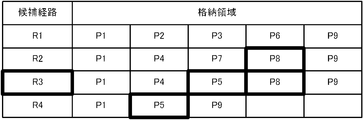
まず、プロセッサ11は、複数の候補経路を決定する(ステップS201)。例えば、図9に示すように、物品330の移動元がP1により示される格納領域310であり、物品330の移動先がP9により示される格納領域310であるものとする。この場合、例えば、R1、R2、R3、及び、R4の4個の候補経路を決定する。R1は、P1、P2、P3、P6、及び、P9の順に格納領域310を通過する経路である。R2は、P1、P4、P7、P8、及び、P9の順に格納領域310を通過する経路である。R3は、P1、P4、P5、P8、及び、P9の順に格納領域310を通過する経路である。R4は、P1、P5、及び、P9の順に格納領域310を通過する経路である。
プロセッサ11は、ステップS201の処理を完了すると、1つの候補経路を選択する(ステップS202)。例えば、プロセッサ11は、R1、R2、R3、及び、R4の4個の候補経路からR1を選択する。プロセッサ11は、ステップS202の処理を完了すると、選択した1つの候補経路について、通過する格納領域310を全て特定する(ステップS203)。例えば、プロセッサ11は、選択したR1について、P1、P2、P3、P6、及び、P9を特定する。プロセッサ11は、ステップS203の処理を完了すると、未選択の候補経路があるか否かを判別する(ステップS204)。
プロセッサ11は、未選択の候補経路があると判別すると(ステップS204:YES)、ステップS202に処理を戻し、未選択の候補経路の中から1つの候補経路を選択する。一方、プロセッサ11は、未選択の候補経路がないと判別すると(ステップS204:NO)、特定した全ての格納領域310を温度情報の取得時刻順にソートする(ステップS205)。
プロセッサ11は、ステップS205の処理を完了すると、温度情報の取得時刻が最も古い格納領域310を特定する(ステップS206)。プロセッサ11は、ステップS206の処理を完了すると、特定した格納領域310を通過する候補経路を移動経路に決定する(ステップS207)。
例えば、P8、P7、P2、P3、P4、P5、P6、P9、及び、P1の順に、温度情報の取得時刻が古いものとする。この場合、プロセッサ11は、取得時刻が最も古い格納領域310として、P8を特定する。ここで、図10に示すように、P8を通過する候補経路として、R2とR3との2つの候補経路が存在するものとする。この場合、2つの候補経路のうち、温度情報の取得時刻がP8の次に古いP7を通過する経路であるR2が特定される。そして、R2が移動経路として決定される。なお、2つの候補経路のうち、温度情報の取得時刻がP8の次に古いP7を通過する経路が存在しない場合、温度情報の取得時刻がP7の次に古いP2を通過する経路が移動経路として決定される。プロセッサ11は、ステップS207の処理を完了すると、経路決定処理を完了する。
プロセッサ11は、ステップS102の経路決定処理を完了すると、搬機410の移動を開始する(ステップS103)。例えば、プロセッサ11は、移動経路を示す経路情報と移動の開始を指示する開始指示情報とを、制御部440に送信する。一方、制御部440は、経路指示装置100から経路情報と開始指示情報とを受信したことに応答して、搬機410の移動を開始する。具体的には、制御部440は、経路情報に従った制御信号により上下移動部431と左右移動部432とを制御する処理を開始する。また、制御部440は、経路指示装置100から経路情報と開始指示情報とを受信したことに応答して、読取装置420に第1電波を放射させる処理を開始させる。
プロセッサ11は、ステップS103の処理を完了すると、第2電波を受信したか否かを判別する(ステップS104)。例えば、プロセッサ11は、制御部440から第2電波を受信した旨を通知する通知情報が第1通信インターフェース14により受信されたか否かを判別する。プロセッサ11は、第2電波を受信したと判別すると(ステップS104:YES)、温度情報と識別情報とを取得する(ステップS105)。例えば、プロセッサ11は、制御部440に、温度情報と識別情報との送信を要求する要求情報を送信する。一方、制御部440は、この要求情報を受信したことに応答して、第2電波に含まれる温度情報と識別情報とを、経路指示装置100に送信する。
プロセッサ11は、ステップS105の処理を完了すると、温度情報と識別情報とを送信する(ステップS106)。つまり、プロセッサ11は、第2通信インターフェース15を介して、温度情報と識別情報とを温度情報収集装置200に送信する。一方、温度情報収集装置200は、経路指示装置100から受信した温度情報と識別情報とを、温度情報と識別情報との取得時刻を示す時刻情報と対応付けて記憶する。
プロセッサ11は、第2電波を受信していないと判別した場合(ステップS104:NO)、又は、ステップS106の処理を完了した場合、搬機410の移動が完了したか否かを判別する(ステップS107)。例えば、プロセッサ11は、制御部440から搬機410の移動が完了した旨を通知する通知情報が第1通信インターフェース14により受信されたか否かを判別する。プロセッサ11は、搬機410の移動が完了していないと判別すると(ステップS107:NO)、ステップS104に処理を戻す。
一方、プロセッサ11は、搬機410の移動が完了したと判別すると(ステップS107:YES)、物品330を指定棚に格納する(ステップS108)。プロセッサ11は、例えば、第1通信インターフェース14を介して、搬機410に物品330を指定棚に格納させることを制御部440に指示する。一方、制御部440は、この指示に従った制御信号を、移動部430に送信する。移動部430は、この制御信号に従って、搬機410に物品330を指定棚に格納させる。プロセッサ11は、ステップS108の処理を完了すると、物品格納処理を完了する。
以上説明したように、本実施形態では、複数の格納領域310のそれぞれに温度計測装置320が設置され、物品330を積載する搬機410に読取装置420が設置される。従って、ラック棚300が備える複数の格納領域310の温度を短時間で効率良く計測することができる。
また、本実施形態では、温度計測装置320が測温抵抗体328を備え、温度計測装置320から読取装置420に無線通信により温度情報が送信される。ここで、測温抵抗体328による温度計測に要する時間はわずかであり、また、無線通信により温度情報を送信する時間もわずかである。このため、格納領域310の温度を瞬時に計測することができる。
また、本実施形態では、温度計測装置320は、温度センサ321が組み込まれたパッシブ型のRFIDタグを含み、読取装置420から受信した第1電波による電力で動作する。このため、温度計測装置320に電源を設ける必要がなく、低コスト化が期待できる。
また、本実施形態では、温度情報と対応付けて記憶された識別情報と時刻情報とに基づいて移動経路が決定される。より詳細には、複数の候補経路のうち、温度情報が収集された時刻が最も古い格納領域310を通過する候補経路が、移動経路として決定される。このため、温度情報が長期間に亘って取得されない格納領域310が発生することを抑制することができる。
(実施形態2)
実施形態1では、複数の候補経路のうち、温度情報が収集された時刻が最も古い格納領域310を通過する候補経路が、移動経路として決定される例について説明した。本発明において、複数の候補経路から移動経路を決定する方法は、この例に限定されない。以下、基本的に、実施形態1と異なる部分について説明する。
実施形態1では、複数の候補経路のうち、温度情報が収集された時刻が最も古い格納領域310を通過する候補経路が、移動経路として決定される例について説明した。本発明において、複数の候補経路から移動経路を決定する方法は、この例に限定されない。以下、基本的に、実施形態1と異なる部分について説明する。
まず、経路指示装置100は、物品330の格納先又は物品330の格納元の格納領域310を指定する領域指定情報に基づいて、移動経路の候補である複数の候補経路を決定する。そして、経路指示装置100は、決定した複数の候補経路のうち温度情報が収集された時刻と現在時刻との時間差が予め定められた閾値(例えば、1週間)以上である格納領域310を最も多く通過する候補領域を、移動経路として決定する。つまり、経路指示装置100は、温度情報の取得時刻が古い格納領域310を多く含む候補経路を、移動経路として採用する。
例えば、図11に示すように、R1、R2、R3、及び、R4の4個の候補領域が決定されたものとする。また、P5とP8とは、温度情報が1週間以上取得されておらず、P1とP2とP3とP4とP6とP7とP9とは、温度情報が1週間以内に取得されたものとする。R1は、温度情報が1週間以上取得されていない格納領域310を通過しない候補経路である。R2は、温度情報が1週間以上取得されていない格納領域310を1個通過する候補経路である。R3は、温度情報が1週間以上取得されていない格納領域310を2個通過する候補経路である。R4は、温度情報が1週間以上取得されていない格納領域310を1個通過する候補経路である。そこで、R3が移動経路として決定されることが好適である。
本実施形態では、複数の候補経路のうち温度情報が収集された時刻と現在時刻との時間差が予め定められた閾値以上である格納領域310を最も多く通過する候補領域が、移動経路として決定される。従って、温度情報の取得時刻が比較的古い多くの格納領域310に関する温度情報を、一回の移動で収集することができる。
(実施形態3)
実施形態1では、第1方向及び第2方向における移動時間が最短である経路のみが複数の候補経路に含まれる例について説明した。本発明において、第1方向又は第2方向における移動時間が最短でない経路が複数の候補経路に含まれていてもよい。以下、基本的に、実施形態1と異なる部分について説明する。
実施形態1では、第1方向及び第2方向における移動時間が最短である経路のみが複数の候補経路に含まれる例について説明した。本発明において、第1方向又は第2方向における移動時間が最短でない経路が複数の候補経路に含まれていてもよい。以下、基本的に、実施形態1と異なる部分について説明する。
本実施形態は、搬機410の第2方向における移動時間が搬機410の第1方向における移動時間に対して十分に長い場合に有効である。例えば、搬機410の第1方向における移動速度と搬機410の第2方向における移動速度とが同程度である場合において、搬機410の第2方向における移動距離が搬機410の第1方向における移動距離に対して十分に長い場合に有効である。或いは、搬機410の第1方向における移動距離と搬機410の第2方向における移動距離とが同程度である場合において、搬機410の第2方向における移動速度が搬機410の第1方向における移動速度に対して十分に遅い場合に有効である。
経路指示装置100は、搬機410の第2方向における移動時間が搬機410の第1方向における移動時間よりも長く、第1方向においては逆戻りし、第2方向においては逆戻りしない経路を含む複数の候補経路を決定する。図12に、搬機410の第1方向における移動距離と搬機410の第2方向における移動距離とが同程度である場合において、搬機410の第2方向における移動速度が搬機410の第1方向における移動速度に対して十分に遅い例を示す。なお、第1方向はZ軸方向であり、第2方向はY軸方向である。
図12には、P1からP9までの経路として、R11、R12、及び、R13の3つの候補経路が決定された例が示されている。ここで、R13は、P1、P4、P7、P8、P5、P6、及び、P9の順に通過する経路である。R13は、第1方向においては逆戻りし、第2方向においては逆戻りしない経路である。R13が移動経路として決定されると、比較的多くの格納領域310を通過することができるため、多くの温度情報を取得することが可能となる。一方、搬機410がP1からP9に移動する時間は、R13が移動経路として決定された場合でも、R11又はR12が移動経路として決定された場合と同様に、最短時間である。
以上説明したように、本実施形態によれば、1回の移動でより多くの温度情報を取得することが可能となる。
(実施形態4)
実施形態1では、温度計測処理が物品格納処理に含まれる例について説明した。本発明において、温度計測処理が物品格納処理とは別に実行されてもよい。以下、図13を参照して、本実施形態に係る経路指示装置100が実行する温度計測処理について説明する。
実施形態1では、温度計測処理が物品格納処理に含まれる例について説明した。本発明において、温度計測処理が物品格納処理とは別に実行されてもよい。以下、図13を参照して、本実施形態に係る経路指示装置100が実行する温度計測処理について説明する。
まず、プロセッサ11は、物品格納指示があるか否かを判別する(ステップS301)。例えば、プロセッサ11は、タッチスクリーン13に物品格納指示に対応する操作がなされたか否かを判別する。プロセッサ11は、物品格納指示があると判別すると(ステップS301:YES)、物品格納処理を実行する(ステップS302)。この物品格納処理は、基本的に、図6に示す物品格納処理と同様である。
プロセッサ11は、物品格納指示がないと判別した場合(ステップS301:NO)、又は、ステップS302の処理を完了した場合、物品取出指示があるか否かを判別する(ステップS303)。例えば、プロセッサ11は、タッチスクリーン13に物品取出指示に対応する操作がなされたか否かを判別する。プロセッサ11は、物品取出指示があると判別すると(ステップS303:YES)、物品取出処理を実行する(ステップS304)。この物品取出処理は、物品330の格納と物品330の取出とが異なる点を除き、基本的に、図6に示す物品格納処理と同様の処理である。
プロセッサ11は、物品取出指示がないと判別した場合(ステップS303:NO)、又は、ステップS304の処理を完了した場合、温度情報が1週間以上未取得の格納領域310があるか否かを判別する(ステップS305)。プロセッサ11は、温度情報が1週間以上未取得の格納領域310がないと判別すると(ステップS305:NO)、ステップS301に処理を戻す。一方、プロセッサ11は、温度情報が1週間以上未取得の格納領域310があると判別すると(ステップS305:YES)、経路決定処理を実行する(ステップS306)。この経路決定処理では、温度情報が1週間以上未取得の格納領域310である第1格納領域を通過する経路を、移動経路として決定する。
プロセッサ11は、ステップS306の処理を完了すると、搬機410の移動を開始する(ステップS307)。プロセッサ11は、ステップS307の処理を完了すると、第2電波を受信したか否かを判別する(ステップS308)。プロセッサ11は、第2電波を受信したと判別すると(ステップS308:YES)、温度情報と識別情報とを取得し(ステップS309)、温度情報と識別情報とを送信する(ステップS310)。
プロセッサ11は、第2電波を受信していないと判別した場合(ステップS308:NO)、又は、ステップS310の処理を完了した場合、搬機410の移動が完了したか否かを判別する(ステップS311)。プロセッサ11は、搬機410の移動が完了していないと判別すると(ステップS311:NO)、ステップS308に処理を戻す。一方、プロセッサ11は、搬機410の移動が完了したと判別すると(ステップS311:YES)、ステップS301に処理を戻す。
本実施形態によれば、長期間に亘って温度情報が取得されない格納領域310が生じないようにすることができる。
(変形例)
以上、本発明の実施形態を説明したが、本発明を実施するにあたっては、種々の形態による変形及び応用が可能である。
以上、本発明の実施形態を説明したが、本発明を実施するにあたっては、種々の形態による変形及び応用が可能である。
本発明において、上記実施形態において説明した構成、機能、動作のどの部分を採用するのかは任意である。また、本発明において、上述した構成、機能、動作のほか、更なる構成、機能、動作が採用されてもよい。また、上記実施形態において説明した構成、機能、動作は、自由に組み合わせることができる。
例えば、実施形態1では、経路指示装置100と温度情報収集装置200とが別々の装置である例について説明した。本発明において、経路指示装置100が温度情報収集装置200に組み込まれていてもよいし、温度情報収集装置200が経路指示装置100に組み込まれていてもよい。また、経路指示装置100又は温度情報収集装置200が、制御部440に組み込まれていてもよい。
実施形態1では、物品330の格納時に温度情報が取得される例について説明した。本発明において、物品330の取出時に温度情報が取得されてもよい。いずれの場合においても、搬機410の移動経路上の格納領域310の温度情報が取得可能である。また、実施形態4で説明したように、物品330の移動を伴わずに、温度情報が取得されてもよい。
実施形態1では、温度計測装置320が、電流測定により温度を計測する例について説明した。本発明において、温度計測装置320が、電圧測定により温度を計測する例について説明した。この場合、温度計測装置320は、測温抵抗体328に一定電圧を印加して測温抵抗体328に流れる電流を測定する電流測定回路329に代えて、測温抵抗体328に一定電流を流して測温抵抗体328に印加される電圧を測定する電圧測定回路(図示せず)を備える。
実施形態1では、棚板340の手前側の端部に温度計測装置320が設置され、搬機410の手前側の底部に読取装置420が設置される例について説明した。本発明において、温度計測装置320及び読取装置420が設置される位置はこの例に限定されない。また、実施形態1では、温度計測装置320の厚み方向と読取装置420の厚み方向とが前後方向であるX軸方向である例について説明した。本発明において、温度計測装置320及び読取装置420が設置される角度はこの例に限定されない。ただし、温度計測装置320及び読取装置420は、温度計測装置320と読取装置420とが通信可能となる位置及び角度で設置されることが望まれる。つまり、温度計測装置320と読取装置420との距離がなるべく近く、温度計測装置320が備えるアンテナ326の放射面と読取装置420が備えるアンテナ422の放射面とがなるべく平行であることが好適である。また、温度計測装置320及び読取装置420は、搬機410による物品330の搬送時に破損しない位置及び角度で設置されることが望まれる。
本発明に係る経路指示装置100の動作を規定する動作プログラムを既存のパーソナルコンピュータ又は情報端末装置に適用することで、当該パーソナルコンピュータ等を本発明に係る経路指示装置100として機能させることも可能である。また、このようなプログラムの配布方法は任意であり、例えば、CD-ROM(Compact Disk Read-Only Memory)、DVD(Digital Versatile Disk)、メモリカードなどのコンピュータ読み取り可能な記録媒体に格納して配布してもよいし、インターネットなどの通信ネットワークを介して配布してもよい。
本発明は、本発明の広義の精神と範囲を逸脱することなく、様々な実施形態及び変形が可能とされるものである。また、上述した実施形態は、本発明を説明するためのものであり、本発明の範囲を限定するものではない。つまり、本発明の範囲は、実施形態ではなく、請求の範囲によって示される。そして、請求の範囲内及びそれと同等の発明の意義の範囲内で施される様々な変形が、本発明の範囲内とみなされる。
本発明は、ラック棚と運搬装置とを備える自動倉庫に適用可能である。
11,21 プロセッサ、12,22 フラッシュメモリ、13,23 タッチスクリーン、14 第1通信インターフェース、15 第2通信インターフェース、24 通信インターフェース、100 経路指示装置、101,201,440 制御部、102 指示受付部、103 第1通信部、104 第2通信部、200 温度情報収集装置、202 温度情報記憶部、203 通信部、300 ラック棚、310 格納領域、320 温度計測装置、321 温度センサ、322 識別情報記憶部、323 電波送受信部、324,421,441 制御回路、325 電源生成回路、326,422 アンテナ、327 記憶回路、328 測温抵抗体、329 電流測定回路、330 物品、340 棚板、341,411 積載部、342,412 側壁部、400 運搬装置、410 搬機、420 読取装置、423 通信回路、430 移動部、431 上下移動部、432 左右移動部、433 第1移動部、434 第2移動部、442 第1通信回路、443 第2通信回路、444 第3通信回路、451 上下移動用レール、452 左右移動用レール、1000 温度計測システム、2000 自動倉庫
Claims (17)
- 複数の格納領域を有するラック棚と、前記複数の格納領域のいずれかに格納される物品を積載する搬機と制御信号に従って前記搬機を移動させる移動手段とを備える運搬装置と、を備える自動倉庫において、前記複数の格納領域の温度を計測する温度計測システムであって、
前記複数の格納領域のそれぞれに設置され、前記格納領域の温度を計測する温度センサと、前記格納領域を識別するための識別情報を記憶する識別情報記憶手段と、第1電波を受信したことに応答して前記第1電波から生成した電力を用いて、前記温度センサにより計測された前記温度を示す温度情報と前記識別情報記憶手段に記憶された前記識別情報とを含む第2電波を送信する電波送受信手段と、を備える温度計測装置と、
前記搬機に設置され、前記第1電波を送信し、前記複数の格納領域に設置された複数の前記温度計測装置のうち前記搬機に最も近い前記温度計測装置により送信された前記第2電波を受信し、前記第2電波に含まれる前記温度情報と前記識別情報とを取得する読取装置と、
前記読取装置により取得された前記温度情報と前記識別情報とを収集する温度情報収集装置と、を備える、
温度計測システム。 - 前記運搬装置は、前記搬機の移動経路を示す経路情報に基づいて前記制御信号を生成し、生成した前記制御信号に従って前記移動手段を制御する制御手段を更に備え、
前記温度情報収集装置は、前記温度情報と、前記識別情報と、前記温度情報と前記識別情報とを収集した時刻を示す時刻情報と、を対応付けて記憶する温度情報記憶手段を備え、
前記温度情報記憶手段に前記温度情報と対応付けて記憶された前記識別情報と前記時刻情報とに基づいて前記移動経路を決定し、決定した前記移動経路を示す前記経路情報を前記制御手段に送信する経路指示装置を更に備える、
請求項1に記載の温度計測システム。 - 前記経路指示装置は、前記物品の格納先又は格納元の格納領域を指定する領域指定情報に基づいて前記移動経路の候補である複数の候補経路を決定し、決定した前記複数の候補経路のうち前記温度情報が収集された時刻が最も古い格納領域を通過する候補経路を、前記移動経路として決定する、
請求項2に記載の温度計測システム。 - 前記経路指示装置は、前記物品の格納先又は格納元の格納領域を指定する領域指定情報に基づいて前記移動経路の候補である複数の候補経路を決定し、決定した前記複数の候補経路のうち前記温度情報が収集された時刻と現在時刻との時間差が予め定められた閾値以上である格納領域を最も多く通過する候補経路を、前記移動経路として決定する、
請求項2に記載の温度計測システム。 - 前記複数の格納領域は、第1方向と前記第1方向に直交する第2方向とに並び、
前記移動手段は、前記第1方向に延びる第1移動用レールに沿って前記搬機を前記第1方向に移動させる第1移動手段と、前記第2方向に延びる第2移動用レールに沿って前記搬機を前記第2方向に移動させる第2移動手段と、を備え、
前記経路指示装置は、前記搬機の前記第2方向における移動時間が前記搬機の前記第1方向における移動時間よりも長く、前記第1方向においては逆戻りし、前記第2方向においては逆戻りしない経路を含む前記複数の候補経路を決定する、
請求項3又は4に記載の温度計測システム。 - 前記経路指示装置は、前記複数の格納領域のうち前記温度情報が収集された時刻と現在時刻との時間差が予め定められた閾値以上である第1格納領域が存在する場合、前記第1格納領域を通過する経路を、前記移動経路として決定する、
請求項2に記載の温度計測システム。 - 複数の格納領域を有するラック棚と、前記複数の格納領域のいずれかに格納される物品を積載する搬機と制御信号に従って前記搬機を移動させる移動手段とを備える運搬装置と、を備える自動倉庫において、前記複数の格納領域の温度を計測する温度計測方法であって、
前記格納領域の温度を計測する温度センサと、前記格納領域を識別するための識別情報を記憶する識別情報記憶手段と、第1電波を受信したことに応答して前記第1電波から生成した電力を用いて、前記温度センサにより計測された前記温度を示す温度情報と前記識別情報記憶手段に記憶された前記識別情報とを含む第2電波を送信する電波送受信手段と、を備える温度計測装置を、前記複数の格納領域のそれぞれに設置し、
前記第1電波を送信し、前記複数の格納領域に設置された複数の前記温度計測装置のうち前記搬機に最も近い前記温度計測装置により送信された前記第2電波を受信し、前記第2電波に含まれる前記温度情報と前記識別情報とを取得する読取装置を、前記搬機に設置し、
前記読取装置により取得された前記温度情報と前記識別情報とを収集する、
温度計測方法。 - 前記温度情報と、前記識別情報と、前記温度情報と前記識別情報とを収集した時刻を示す時刻情報と、を対応付けて記憶し、
前記温度情報と対応付けて記憶された前記識別情報と前記時刻情報とに基づいて前記搬機の移動経路を決定し、決定した前記移動経路に基づいて前記制御信号を生成する、
請求項7に記載の温度計測方法。 - 前記物品の格納先又は格納元の格納領域を指定する領域指定情報に基づいて前記移動経路の候補である複数の候補経路を決定し、決定した前記複数の候補経路のうち前記温度情報が収集された時刻が最も古い格納領域を通過する候補経路を、前記移動経路として決定する、
請求項8に記載の温度計測方法。 - 前記物品の格納先又は格納元の格納領域を指定する領域指定情報に基づいて前記移動経路の候補である複数の候補経路を決定し、決定した前記複数の候補経路のうち前記温度情報が収集された時刻と現在時刻との時間差が予め定められた閾値以上である格納領域を最も多く通過する候補経路を、前記移動経路として決定する、
請求項8に記載の温度計測方法。 - 前記複数の格納領域は、第1方向と前記第1方向に直交する第2方向とに並び、
前記移動手段は、前記第1方向に延びる第1移動用レールに沿って前記搬機を前記第1方向に移動させる第1移動手段と、前記第2方向に延びる第2移動用レールに沿って前記搬機を前記第2方向に移動させる第2移動手段と、を備え、
前記搬機の前記第2方向における移動時間が前記搬機の前記第1方向における移動時間よりも長く、前記第1方向においては逆戻りし、前記第2方向においては逆戻りしない経路を含む前記複数の候補経路を決定する、
請求項9又は10に記載の温度計測方法。 - 前記複数の格納領域のうち前記温度情報が収集された時刻と現在時刻との時間差が予め定められた閾値以上である第1格納領域が存在する場合、前記第1格納領域を通過する経路を、前記移動経路として決定する、
請求項8に記載の温度計測方法。 - 複数の格納領域を有するラック棚と、
前記複数の格納領域のいずれかに格納される物品を積載する搬機と、制御信号に従って前記搬機を移動させる移動手段と、前記搬機の移動経路を示す経路情報に基づいて前記制御信号を生成し、生成した前記制御信号に従って前記移動手段を制御する制御手段と、を備える運搬装置と、
前記複数の格納領域のそれぞれに設置され、前記格納領域の温度を計測する温度センサと、前記格納領域を識別するための識別情報を記憶する識別情報記憶手段と、第1電波を受信したことに応答して前記第1電波から生成した電力を用いて、前記温度センサにより計測された前記温度を示す温度情報と前記識別情報記憶手段に記憶された前記識別情報とを含む第2電波を送信する電波送受信手段と、を備える温度計測装置と、
前記搬機に設置され、前記第1電波を送信し、前記複数の格納領域に設置された複数の前記温度計測装置のうち前記搬機に最も近い前記温度計測装置により送信された前記第2電波を受信し、前記第2電波に含まれる前記温度情報と前記識別情報とを取得する読取装置と、
前記読取装置により取得された前記温度情報と前記識別情報とを収集し、前記温度情報と、前記識別情報と、前記温度情報と前記識別情報とを収集した時刻を示す時刻情報と、を対応付けて記憶する温度情報記憶手段を備える温度情報収集装置と、を備える自動倉庫において、前記制御手段に前記経路情報を送信するコンピュータを、
前記温度情報記憶手段に前記温度情報と対応付けて記憶された前記識別情報と前記時刻情報とに基づいて前記移動経路を決定する経路決定手段、
前記経路決定手段により決定された前記移動経路を示す前記経路情報を前記制御手段に送信する経路情報送信手段、として機能させる、
プログラム。 - 前記経路決定手段は、前記物品の格納先又は格納元の格納領域を指定する領域指定情報に基づいて前記移動経路の候補である複数の候補経路を決定し、決定した前記複数の候補経路のうち前記温度情報が収集された時刻が最も古い格納領域を通過する候補経路を、前記移動経路として決定する、
請求項13に記載のプログラム。 - 前記経路決定手段は、前記物品の格納先又は格納元の格納領域を指定する領域指定情報に基づいて前記移動経路の候補である複数の候補経路を決定し、決定した前記複数の候補経路のうち前記温度情報が収集された時刻と現在時刻との時間差が予め定められた閾値以上である格納領域を最も多く通過する候補経路を、前記移動経路として決定する、
請求項13に記載のプログラム。 - 前記複数の格納領域は、第1方向と前記第1方向に直交する第2方向とに並び、
前記移動手段は、前記第1方向に延びる第1移動用レールに沿って前記搬機を前記第1方向に移動させる第1移動手段と、前記第2方向に延びる第2移動用レールに沿って前記搬機を前記第2方向に移動させる第2移動手段と、を備え、
前記経路決定手段は、前記搬機の前記第2方向における移動時間が前記搬機の前記第1方向における移動時間よりも長く、前記第1方向においては逆戻りし、前記第2方向においては逆戻りしない経路を含む前記複数の候補経路を決定する、
請求項14又は15に記載のプログラム。 - 前記経路決定手段は、前記複数の格納領域のうち前記温度情報が収集された時刻と現在時刻との時間差が予め定められた閾値以上である第1格納領域が存在する場合、前記第1格納領域を通過する経路を、前記移動経路として決定する、
請求項13に記載のプログラム。
Priority Applications (2)
| Application Number | Priority Date | Filing Date | Title |
|---|---|---|---|
| PCT/JP2018/024472 WO2020003426A1 (ja) | 2018-06-27 | 2018-06-27 | 温度計測システム、温度計測方法、及び、プログラム |
| JP2020526795A JP6972339B2 (ja) | 2018-06-27 | 2018-06-27 | 温度計測システム、温度計測方法、及び、プログラム |
Applications Claiming Priority (1)
| Application Number | Priority Date | Filing Date | Title |
|---|---|---|---|
| PCT/JP2018/024472 WO2020003426A1 (ja) | 2018-06-27 | 2018-06-27 | 温度計測システム、温度計測方法、及び、プログラム |
Publications (1)
| Publication Number | Publication Date |
|---|---|
| WO2020003426A1 true WO2020003426A1 (ja) | 2020-01-02 |
Family
ID=68986723
Family Applications (1)
| Application Number | Title | Priority Date | Filing Date |
|---|---|---|---|
| PCT/JP2018/024472 Ceased WO2020003426A1 (ja) | 2018-06-27 | 2018-06-27 | 温度計測システム、温度計測方法、及び、プログラム |
Country Status (2)
| Country | Link |
|---|---|
| JP (1) | JP6972339B2 (ja) |
| WO (1) | WO2020003426A1 (ja) |
Cited By (1)
| Publication number | Priority date | Publication date | Assignee | Title |
|---|---|---|---|---|
| JP7668173B2 (ja) | 2021-06-29 | 2025-04-24 | 株式会社竹中工務店 | 温度センサ設置機構及び温度測定方法 |
Citations (3)
| Publication number | Priority date | Publication date | Assignee | Title |
|---|---|---|---|---|
| JPH07206114A (ja) * | 1994-01-25 | 1995-08-08 | Kito Corp | 自動倉庫の温度計測装置 |
| JP2007094864A (ja) * | 2005-09-29 | 2007-04-12 | Oki Electric Ind Co Ltd | Rfidタグ及び非接触データキャリアシステム |
| JP2008285250A (ja) * | 2007-05-16 | 2008-11-27 | Nippon Yusoki Co Ltd | Idタグを用いた荷物管理システム |
-
2018
- 2018-06-27 WO PCT/JP2018/024472 patent/WO2020003426A1/ja not_active Ceased
- 2018-06-27 JP JP2020526795A patent/JP6972339B2/ja not_active Expired - Fee Related
Patent Citations (3)
| Publication number | Priority date | Publication date | Assignee | Title |
|---|---|---|---|---|
| JPH07206114A (ja) * | 1994-01-25 | 1995-08-08 | Kito Corp | 自動倉庫の温度計測装置 |
| JP2007094864A (ja) * | 2005-09-29 | 2007-04-12 | Oki Electric Ind Co Ltd | Rfidタグ及び非接触データキャリアシステム |
| JP2008285250A (ja) * | 2007-05-16 | 2008-11-27 | Nippon Yusoki Co Ltd | Idタグを用いた荷物管理システム |
Cited By (1)
| Publication number | Priority date | Publication date | Assignee | Title |
|---|---|---|---|---|
| JP7668173B2 (ja) | 2021-06-29 | 2025-04-24 | 株式会社竹中工務店 | 温度センサ設置機構及び温度測定方法 |
Also Published As
| Publication number | Publication date |
|---|---|
| JP6972339B2 (ja) | 2021-11-24 |
| JPWO2020003426A1 (ja) | 2020-12-17 |
Similar Documents
| Publication | Publication Date | Title |
|---|---|---|
| US11176512B2 (en) | Concepts for locating assets utilizing light detection and ranging | |
| US9964958B2 (en) | Driverless vehicle, and apparatus, system, and method of vehicle control | |
| JP4905544B2 (ja) | 作業管理システム及び作業管理方法 | |
| JP6474370B2 (ja) | タグid識別システム | |
| US11376634B2 (en) | Article management device, article management system, and computer-readable storage medium | |
| US10565410B1 (en) | Overhead RFID antenna | |
| KR101947736B1 (ko) | 상품 분류 장치, 방법, 및 컴퓨터 프로그램 | |
| JP6641245B2 (ja) | 荷物管理システム | |
| JP7136489B2 (ja) | 物品位置推定システム及び物品位置推定方法 | |
| US20210206572A1 (en) | Wireless tag reading system | |
| KR102740806B1 (ko) | 컨테이너 운송 상태 정보 제공 장치 및 그 장치의 제어 방법 | |
| JP6972339B2 (ja) | 温度計測システム、温度計測方法、及び、プログラム | |
| JP2021009553A (ja) | 分析システム、分析方法、プログラム、及び記憶媒体 | |
| JP2018127298A (ja) | 物品位置管理システム | |
| KR20130065824A (ko) | Rfid 태그의 위치 정보를 이용한 재고 관리 방법 및 그 장치 | |
| JP6347533B1 (ja) | 位置特定方法、位置特定装置およびプログラム | |
| JP2016028979A (ja) | 図書収容装置 | |
| JP4449763B2 (ja) | 移動体、情報受信機、進行方向判別装置、進行方向判別方法、および、進行方向判別プログラム | |
| JP2005170579A (ja) | 情報管理システム | |
| JP7454608B2 (ja) | マテリアルハンドリング環境内の資産の場所を推定する方法及びシステム | |
| CN113947347A (zh) | 一种智能装置、监控方法、电子设备及存储介质 | |
| CN105989453A (zh) | 货物托运监控系统 | |
| US20250155546A1 (en) | Information processing system | |
| JP2018052627A (ja) | 荷物管理システム | |
| JP2020030526A (ja) | 位置情報管理装置、位置情報管理システム、搬送装置、位置情報管理方法及びプログラム |
Legal Events
| Date | Code | Title | Description |
|---|---|---|---|
| 121 | Ep: the epo has been informed by wipo that ep was designated in this application |
Ref document number: 18925025 Country of ref document: EP Kind code of ref document: A1 |
|
| ENP | Entry into the national phase |
Ref document number: 2020526795 Country of ref document: JP Kind code of ref document: A |
|
| NENP | Non-entry into the national phase |
Ref country code: DE |
|
| 122 | Ep: pct application non-entry in european phase |
Ref document number: 18925025 Country of ref document: EP Kind code of ref document: A1 |