WO2020003399A1 - 内視鏡システム - Google Patents
内視鏡システム Download PDFInfo
- Publication number
- WO2020003399A1 WO2020003399A1 PCT/JP2018/024337 JP2018024337W WO2020003399A1 WO 2020003399 A1 WO2020003399 A1 WO 2020003399A1 JP 2018024337 W JP2018024337 W JP 2018024337W WO 2020003399 A1 WO2020003399 A1 WO 2020003399A1
- Authority
- WO
- WIPO (PCT)
- Prior art keywords
- light
- temperature
- amount
- laser diode
- endoscope
- Prior art date
- Legal status (The legal status is an assumption and is not a legal conclusion. Google has not performed a legal analysis and makes no representation as to the accuracy of the status listed.)
- Ceased
Links
Images







Classifications
-
- G—PHYSICS
- G02—OPTICS
- G02B—OPTICAL ELEMENTS, SYSTEMS OR APPARATUS
- G02B23/00—Telescopes, e.g. binoculars; Periscopes; Instruments for viewing the inside of hollow bodies; Viewfinders; Optical aiming or sighting devices
- G02B23/24—Instruments or systems for viewing the inside of hollow bodies, e.g. fibrescopes
- G02B23/2407—Optical details
- G02B23/2461—Illumination
- G02B23/2469—Illumination using optical fibres
-
- A—HUMAN NECESSITIES
- A61—MEDICAL OR VETERINARY SCIENCE; HYGIENE
- A61B—DIAGNOSIS; SURGERY; IDENTIFICATION
- A61B1/00—Instruments for performing medical examinations of the interior of cavities or tubes of the body by visual or photographical inspection, e.g. endoscopes; Illuminating arrangements therefor
- A61B1/00002—Operational features of endoscopes
- A61B1/00004—Operational features of endoscopes characterised by electronic signal processing
- A61B1/00006—Operational features of endoscopes characterised by electronic signal processing of control signals
-
- A—HUMAN NECESSITIES
- A61—MEDICAL OR VETERINARY SCIENCE; HYGIENE
- A61B—DIAGNOSIS; SURGERY; IDENTIFICATION
- A61B1/00—Instruments for performing medical examinations of the interior of cavities or tubes of the body by visual or photographical inspection, e.g. endoscopes; Illuminating arrangements therefor
- A61B1/04—Instruments for performing medical examinations of the interior of cavities or tubes of the body by visual or photographical inspection, e.g. endoscopes; Illuminating arrangements therefor combined with photographic or television appliances
- A61B1/044—Instruments for performing medical examinations of the interior of cavities or tubes of the body by visual or photographical inspection, e.g. endoscopes; Illuminating arrangements therefor combined with photographic or television appliances for absorption imaging
-
- A—HUMAN NECESSITIES
- A61—MEDICAL OR VETERINARY SCIENCE; HYGIENE
- A61B—DIAGNOSIS; SURGERY; IDENTIFICATION
- A61B1/00—Instruments for performing medical examinations of the interior of cavities or tubes of the body by visual or photographical inspection, e.g. endoscopes; Illuminating arrangements therefor
- A61B1/06—Instruments for performing medical examinations of the interior of cavities or tubes of the body by visual or photographical inspection, e.g. endoscopes; Illuminating arrangements therefor with illuminating arrangements
- A61B1/0638—Instruments for performing medical examinations of the interior of cavities or tubes of the body by visual or photographical inspection, e.g. endoscopes; Illuminating arrangements therefor with illuminating arrangements providing two or more wavelengths
-
- A—HUMAN NECESSITIES
- A61—MEDICAL OR VETERINARY SCIENCE; HYGIENE
- A61B—DIAGNOSIS; SURGERY; IDENTIFICATION
- A61B1/00—Instruments for performing medical examinations of the interior of cavities or tubes of the body by visual or photographical inspection, e.g. endoscopes; Illuminating arrangements therefor
- A61B1/06—Instruments for performing medical examinations of the interior of cavities or tubes of the body by visual or photographical inspection, e.g. endoscopes; Illuminating arrangements therefor with illuminating arrangements
- A61B1/0653—Instruments for performing medical examinations of the interior of cavities or tubes of the body by visual or photographical inspection, e.g. endoscopes; Illuminating arrangements therefor with illuminating arrangements with wavelength conversion
-
- A—HUMAN NECESSITIES
- A61—MEDICAL OR VETERINARY SCIENCE; HYGIENE
- A61B—DIAGNOSIS; SURGERY; IDENTIFICATION
- A61B1/00—Instruments for performing medical examinations of the interior of cavities or tubes of the body by visual or photographical inspection, e.g. endoscopes; Illuminating arrangements therefor
- A61B1/06—Instruments for performing medical examinations of the interior of cavities or tubes of the body by visual or photographical inspection, e.g. endoscopes; Illuminating arrangements therefor with illuminating arrangements
- A61B1/0655—Control therefor
-
- A—HUMAN NECESSITIES
- A61—MEDICAL OR VETERINARY SCIENCE; HYGIENE
- A61B—DIAGNOSIS; SURGERY; IDENTIFICATION
- A61B1/00—Instruments for performing medical examinations of the interior of cavities or tubes of the body by visual or photographical inspection, e.g. endoscopes; Illuminating arrangements therefor
- A61B1/06—Instruments for performing medical examinations of the interior of cavities or tubes of the body by visual or photographical inspection, e.g. endoscopes; Illuminating arrangements therefor with illuminating arrangements
- A61B1/0661—Endoscope light sources
- A61B1/0669—Endoscope light sources at proximal end of an endoscope
-
- A—HUMAN NECESSITIES
- A61—MEDICAL OR VETERINARY SCIENCE; HYGIENE
- A61B—DIAGNOSIS; SURGERY; IDENTIFICATION
- A61B1/00—Instruments for performing medical examinations of the interior of cavities or tubes of the body by visual or photographical inspection, e.g. endoscopes; Illuminating arrangements therefor
- A61B1/06—Instruments for performing medical examinations of the interior of cavities or tubes of the body by visual or photographical inspection, e.g. endoscopes; Illuminating arrangements therefor with illuminating arrangements
- A61B1/07—Instruments for performing medical examinations of the interior of cavities or tubes of the body by visual or photographical inspection, e.g. endoscopes; Illuminating arrangements therefor with illuminating arrangements using light-conductive means, e.g. optical fibres
-
- A—HUMAN NECESSITIES
- A61—MEDICAL OR VETERINARY SCIENCE; HYGIENE
- A61B—DIAGNOSIS; SURGERY; IDENTIFICATION
- A61B1/00—Instruments for performing medical examinations of the interior of cavities or tubes of the body by visual or photographical inspection, e.g. endoscopes; Illuminating arrangements therefor
- A61B1/12—Instruments for performing medical examinations of the interior of cavities or tubes of the body by visual or photographical inspection, e.g. endoscopes; Illuminating arrangements therefor with cooling or rinsing arrangements
- A61B1/128—Instruments for performing medical examinations of the interior of cavities or tubes of the body by visual or photographical inspection, e.g. endoscopes; Illuminating arrangements therefor with cooling or rinsing arrangements provided with means for regulating temperature
-
- G—PHYSICS
- G02—OPTICS
- G02B—OPTICAL ELEMENTS, SYSTEMS OR APPARATUS
- G02B23/00—Telescopes, e.g. binoculars; Periscopes; Instruments for viewing the inside of hollow bodies; Viewfinders; Optical aiming or sighting devices
- G02B23/24—Instruments or systems for viewing the inside of hollow bodies, e.g. fibrescopes
- G02B23/2476—Non-optical details, e.g. housings, mountings, supports
- G02B23/2484—Arrangements in relation to a camera or imaging device
-
- H—ELECTRICITY
- H01—ELECTRIC ELEMENTS
- H01S—DEVICES USING THE PROCESS OF LIGHT AMPLIFICATION BY STIMULATED EMISSION OF RADIATION [LASER] TO AMPLIFY OR GENERATE LIGHT; DEVICES USING STIMULATED EMISSION OF ELECTROMAGNETIC RADIATION IN WAVE RANGES OTHER THAN OPTICAL
- H01S5/00—Semiconductor lasers
- H01S5/005—Optical components external to the laser cavity, specially adapted therefor, e.g. for homogenisation or merging of the beams or for manipulating laser pulses, e.g. pulse shaping
- H01S5/0087—Optical components external to the laser cavity, specially adapted therefor, e.g. for homogenisation or merging of the beams or for manipulating laser pulses, e.g. pulse shaping for illuminating phosphorescent or fluorescent materials, e.g. using optical arrangements specifically adapted for guiding or shaping laser beams illuminating these materials
-
- H—ELECTRICITY
- H01—ELECTRIC ELEMENTS
- H01S—DEVICES USING THE PROCESS OF LIGHT AMPLIFICATION BY STIMULATED EMISSION OF RADIATION [LASER] TO AMPLIFY OR GENERATE LIGHT; DEVICES USING STIMULATED EMISSION OF ELECTROMAGNETIC RADIATION IN WAVE RANGES OTHER THAN OPTICAL
- H01S5/00—Semiconductor lasers
- H01S5/06—Arrangements for controlling the laser output parameters, e.g. by operating on the active medium
- H01S5/068—Stabilisation of laser output parameters
- H01S5/06804—Stabilisation of laser output parameters by monitoring an external parameter, e.g. temperature
-
- H—ELECTRICITY
- H01—ELECTRIC ELEMENTS
- H01S—DEVICES USING THE PROCESS OF LIGHT AMPLIFICATION BY STIMULATED EMISSION OF RADIATION [LASER] TO AMPLIFY OR GENERATE LIGHT; DEVICES USING STIMULATED EMISSION OF ELECTROMAGNETIC RADIATION IN WAVE RANGES OTHER THAN OPTICAL
- H01S5/00—Semiconductor lasers
- H01S5/06—Arrangements for controlling the laser output parameters, e.g. by operating on the active medium
- H01S5/068—Stabilisation of laser output parameters
- H01S5/0683—Stabilisation of laser output parameters by monitoring the optical output parameters
-
- H—ELECTRICITY
- H01—ELECTRIC ELEMENTS
- H01S—DEVICES USING THE PROCESS OF LIGHT AMPLIFICATION BY STIMULATED EMISSION OF RADIATION [LASER] TO AMPLIFY OR GENERATE LIGHT; DEVICES USING STIMULATED EMISSION OF ELECTROMAGNETIC RADIATION IN WAVE RANGES OTHER THAN OPTICAL
- H01S5/00—Semiconductor lasers
- H01S5/02—Structural details or components not essential to laser action
- H01S5/022—Mountings; Housings
- H01S5/0225—Out-coupling of light
- H01S5/02251—Out-coupling of light using optical fibres
-
- H—ELECTRICITY
- H01—ELECTRIC ELEMENTS
- H01S—DEVICES USING THE PROCESS OF LIGHT AMPLIFICATION BY STIMULATED EMISSION OF RADIATION [LASER] TO AMPLIFY OR GENERATE LIGHT; DEVICES USING STIMULATED EMISSION OF ELECTROMAGNETIC RADIATION IN WAVE RANGES OTHER THAN OPTICAL
- H01S5/00—Semiconductor lasers
- H01S5/06—Arrangements for controlling the laser output parameters, e.g. by operating on the active medium
- H01S5/0617—Arrangements for controlling the laser output parameters, e.g. by operating on the active medium using memorised or pre-programmed laser characteristics
Definitions
- the present invention relates to an endoscope system.
- an endoscope has an elongated insertion portion, irradiates illumination light from an illumination window at a distal end portion of the insertion portion, and reflected light of illumination light from a subject enters an observation window at the distal end portion.
- the endoscope system has a light source that emits illumination light, and the amount of illumination light emitted from the light source is controlled so that the endoscope image has a desired brightness.
- the amount of light emitted from a light source is controlled based on the output of a light receiving element that receives a part of the emitted light.
- a light receiving element that receives a part of the emitted light.
- Japanese Patent Application Laid-Open No. 2012-94891 discloses a technique in which an optical sensor is provided at a position irradiated with laser light to control the optical output of a semiconductor laser chip.
- Japanese Patent Application Laid-Open No. 2017-207412 discloses an optical sensor that detects the light amount of the light emitted by the light source.
- a technology that has a temperature detection mechanism that detects the temperature of a light source and maintains the luminance and chromaticity of the light source constant even when the temperature of the light source changes. Therefore, it is conceivable that these techniques are applied to an endoscope system.
- the light intensity of the light emitted from the light source is detected by the optical sensor, the light intensity of the light emitted from the light source cannot be appropriately controlled because the optical sensor itself has temperature characteristics. If the amount of light emitted from the light source cannot be appropriately controlled, the endoscope image displayed on the display device does not have appropriate brightness.
- An endoscope system receives a light source device that emits illumination light by a light source for an endoscope that can control the amount of light, and receives an imaging signal obtained by receiving reflected light of the illumination light.
- An image acquisition device for acquiring an image by the light source, a light receiving element for receiving a part of the illumination light of the light source, a first temperature sensor for detecting a first temperature of the light source, and a second light receiving element for the light receiving element.
- a second temperature sensor that detects a temperature of the light-receiving element, a light-receiving amount correction unit that corrects a light-receiving amount of the light-receiving element based on the second temperature, and a corrected light-receiving amount corrected by the light-receiving amount correction unit.
- a drive control unit that controls the driving of the light source based on the first temperature so that the light amount of the illumination light becomes a set value.
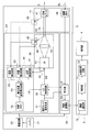
- FIG. 1 is a configuration diagram of an endoscope system according to a first embodiment of the present invention.
- FIG. 1 is a block diagram illustrating a configuration of an endoscope system according to a first embodiment of the present invention.
- FIG. 2 is a partial cross-sectional view showing a photodiode mounting structure according to the first embodiment of the present invention.
- FIG. 2 is a configuration diagram of a distal end unit according to the first embodiment of the present invention.
- FIG. 3 is a diagram illustrating temperature characteristics of a laser diode according to the first embodiment of the present invention.
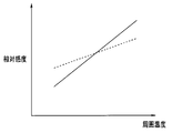
- FIG. 3 is a diagram illustrating a temperature characteristic of a relative sensitivity of the photodiode according to the first embodiment of the present invention.
- FIG. 1 is a configuration diagram of an endoscope system according to a first embodiment of the present invention.
- FIG. 1 is a block diagram illustrating a configuration of an endoscope system according to a first embodiment of the present invention.
- FIG. 2 is a partial
- FIG. 3 is a diagram illustrating an example of a table in which driving conditions of a laser diode are determined according to the first embodiment of the present invention.
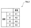
- FIG. 4 is a diagram illustrating an example of a table in which a sensitivity coefficient of a photodiode is determined according to the first embodiment of the present invention.
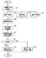
- 6 is a flowchart illustrating an example of a flow of processing for temperature correction of the amount of light emitted from the light emitting unit and drive control of the light source according to the first embodiment of the present invention.
- FIG. 11 is a diagram illustrating an example of a table according to a modification of the first embodiment of the present invention.
- FIG. 13 is a flowchart illustrating an example of a flow of a temperature correction process for the light emission amount of the light emitting unit 33 according to a modification of the first embodiment of the present invention.
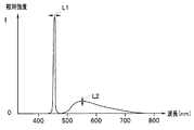
- 9 is a graph illustrating an example of the spectrum of illumination light according to the second embodiment of the present invention.
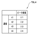
- FIG. 13 is a diagram illustrating an example of a table in which a peak wavelength of a laser diode is determined according to a temperature according to the second embodiment of the present invention.
- FIG. 13 is a diagram illustrating an example of a table in which a sensitivity coefficient of a photodiode is determined according to the second embodiment of the present invention.
- 17 is a diagram illustrating an example of a table for correcting a difference in light amount according to a modification of the second embodiment of the present invention. It is a figure concerning the modification of a 2nd embodiment of the present invention and showing an example of a table for correcting a difference of wavelength of illumination light.
- FIG. 1 is a configuration diagram of an endoscope system according to an embodiment of the present invention.
- the endoscope system 1 includes the endoscope 2, the main body 3, and the display unit 4.
- the endoscope 2 and the main body 3 can communicate with each other wirelessly as indicated by a two-dot chain line.
- the main unit 3 and the display unit 4 are connected by a signal cable (not shown).
- the endoscope 2 has an elongated insertion section 11 and an operation section 12.
- the insertion portion 11 has a tip portion 13, a bending portion 14, and a flexible tube portion 15 in this order from the tip.
- the proximal end of the flexible tube section 15 is connected to the operation section 12.
- the operation unit 12 has a bending operation lever 16 and various operation buttons 17.
- the user of the endoscope 2 can bend the bending section 14 in a desired direction by gripping the operation section 12 and operating the bending operation lever 16.
- the user can freeze the endoscope image or record a frozen still image in the storage device of the main body unit 3 by operating the various operation buttons 17.
- An observation window and an illumination window are provided at the distal end portion 13.
- the illumination light IL is emitted to the subject S from the illumination window, and the reflected light RL of the illumination light IL from the subject S enters the observation window.
- the reflected light RL passes through the imaging optical system and forms an image on the light receiving surface of the imaging element 48 (FIG. 2) in the distal end portion 13.
- An imaging signal from the imaging element 48 is transmitted to the main body 3 wirelessly.
- the endoscope image generated based on the imaging signal from the endoscope 2 is displayed on the display unit 4.
- the endoscope 2 is driven by a battery, and the endoscope 2 and the main body 3 are configured to communicate with each other wirelessly.
- the endoscope 2 and the main body 3 are connected to each other. 3 may be connected by a cable 5.
- power is supplied to the endoscope 2 via the cable 5, and communication between the endoscope 2 and the main body 3 is also performed via a signal line in the cable 5.
- FIG. 2 is a block diagram illustrating a configuration of the endoscope system 1.
- the endoscope 2 has a battery 21 such as a secondary battery and a power supply circuit 22.
- the power supply circuit 22 receives electric power from the battery 21, generates various voltages required by each circuit in the endoscope 2, and supplies the generated voltages to each circuit.
- the endoscope 2 further includes a light source device 23 and an image acquisition device 24.
- the battery 21, the power supply circuit 22, the light source device 23, and the image acquisition device 24 are provided in the operation unit 12 of the endoscope 2.
- the light source device 23 includes an operation mode selection circuit 31, a laser diode control circuit (hereinafter, referred to as an LD control circuit) 32, a light emitting unit 33, and a detected light amount temperature correction unit 34.
- the light emitting unit 33 has a light source whose light amount can be controlled. That is, the light source device 23 emits the illumination light by the light source for the endoscope whose light quantity can be controlled.
- the operation mode selection circuit 31 outputs an instruction signal corresponding to a user operation to the LD control circuit 32.
- the user can give various commands to the endoscope 2 by operating the various operation buttons 17.
- the operation mode selection circuit 31 is a circuit that outputs an instruction signal corresponding to the command signal to the laser diode control circuit 32 and a control unit 61 described later.
- the instruction signal output from the operation mode selection circuit 31 includes a selection signal for the normal observation mode using white light.
- the LD control circuit 32 includes a processor, and the processor includes a central processing unit (CPU), a ROM, and a RAM.
- the LD control circuit 32 receives a light amount signal LM indicating the light amount of the illumination light from the detected light amount temperature correction unit 34.
- the LD control circuit 32 generates a drive signal DD for controlling the driving of the light source of the light emitting unit 33 based on the temperature T1 of the laser diode 41 and the light amount signal LM so that the light amount of the illumination light becomes a set value.
- a drive control unit for outputting is configured. That is, the drive signal DD is determined based on the light amount signal LM from the detected light amount temperature correction unit 34.
- the detected light amount temperature correction circuit 54 constitutes a light reception amount correction unit that outputs a light amount signal LM obtained by correcting the light reception amount of the photodiode 43 based on the temperature of the photodiode 43 detected by the thermistor 45. .
- the LD control circuit 32 operates according to the instruction signal from the operation mode selection circuit 31 and the control signal from the control unit 61. For example, when the normal observation mode is selected as the operation mode, the LD control circuit 32 generates the drive signal DD according to the dimming level from the control unit 61.
- the light emitting unit 33 includes a laser diode (LD) 41 as a semiconductor light emitting element, a condenser lens 42, and a photodiode (PD) 43 as an optical sensor.
- the photodiode 43 is provided in the operation unit 12 of the endoscope 2 or in a portion near the operation unit 12.
- a thermistor 44 is provided in the laser diode 41 as a light source.
- the thermistor 44 is a temperature sensor that detects the temperature of the laser diode 41 as a light source, and is provided near the laser diode 41 on a substrate on which the laser diode 41 is mounted. That is, the thermistor 44 is thermally connected to the laser diode 41.
- the photodiode 43 is provided with a thermistor 45.
- the thermistor 45 is a temperature sensor that is provided in the light emitting unit 33 and detects the temperature of the photodiode 43 that is a light receiving element, and is provided in close contact with or near the photodiode 43. That is, the thermistor 45 is thermally connected to the photodiode 43.
- the mounting structure of the thermistor 45 will be described later.
- the laser diode 41 emits light in response to a drive signal DD which is a drive current from the laser diode control circuit 32.
- the condensing lens 42 condenses the laser light from the laser diode 41 and condenses it on the end face of the base end of the optical fiber 46 connected to the light emitting section 33. Light incident on the end face of the base end of the optical fiber 46 passes through the optical fiber 46 and exits from the end face of the tip of the optical fiber 46 as illumination light.
- the optical fiber 46 is bifurcated on the way so that the illumination light is emitted from the two illumination windows of the distal end portion 13, but the bifurcation is omitted here and not shown.
- the light from the condenser lens 42 is condensed on the end face of the base end of the optical fiber 46.
- the photodiode 43 is disposed at a position where the light reflected on the end face of the base end of the optical fiber 46 can be received. Is done. That is, the photodiode 43 is a light receiving element provided in the light emitting section 33 so as to receive a part of the illumination light of the laser diode 41 as a light source.
- the amount of light received by the photodiode 43 is proportional to the amount of laser light emitted by the laser diode 41.
- the endoscope 2 has the optical fiber 46 for guiding the illumination light, and the photodiode 43 as the light receiving element is arranged near the illumination light incident end of the optical fiber 46. I have.
- the light emitting unit 33 and the optical fiber 46 have a pigtail structure, and the light emitting unit 33 and the optical fiber 46 are formed integrally. Therefore, the optical fiber 46 extends from the light emitting section 33.
- FIG. 3 is a partial cross-sectional view showing a mounting structure of the photodiode 43.
- the light emitting section 33 has a housing 33a for holding the laser diode 41, the lens 42, and the like.
- the opening 33 b is provided in the housing 33 a of the light emitting unit 33.
- the flexible board 33c is fixed to the housing 33a by an adhesive 33d so as to cover the opening 33b.
- the photodiode 43 and the thermistor 45 are mounted on the back surface and the front surface of the flexible substrate 33c, respectively, so as to sandwich the flexible substrate 33c.
- the photodiode 43 is arranged in the housing 33a. That is, the photodiode 43 and the thermistor 45 are mounted on the flexible board 33c with the flexible board 33c being a circuit board interposed therebetween so that the thermistor 45 can accurately detect the temperature of the photodiode 43 through the flexible board 33c.
- the output signal of the photodiode 43 and the output signal of the thermistor 45 are supplied to the light amount detection circuit 53 and the temperature detection circuit 52 through a plurality of signal lines 33e connected to the flexible substrate 33c.
- the optical fiber 46 is inserted into the insertion portion 11. As described above, the base end of the optical fiber 46 is connected to the light emitting unit 33, while the distal end of the optical fiber 46 is connected to the distal end unit 47 provided in the distal end 13.
- the distal end unit 47 of the endoscope 2 has a phosphor and is disposed behind the illumination window (not shown) of the distal end portion 13.
- FIG. 4 is a configuration diagram of the tip unit 47.
- the tip unit 47 has a holder 47a, a transparent member 47b, and a phosphor 47c. Although not shown, the phosphor 47c contains diffusion particles.
- the holder 47a has a partially conical or tapered inner peripheral surface 47d, and a reflective film formed by silver deposition is formed on the inner peripheral surface.
- the tip of the optical fiber 46 is connected to the holder 47a so that light from the end face of the tip of the optical fiber 46 is irradiated into the transparent member 47b.
- the light that has entered the transparent member 47b from the optical fiber 46 goes straight, and the diffused light is reflected by the inner peripheral surface 47d and then enters the phosphor 47c.
- the phosphor 47c performs wavelength conversion of light by fluorescing according to the received light.
- the inner peripheral surface 47d reflects a part of the light emitted from the fluorescent material 47c, and the light emitted from the distal end surface of the optical fiber 46 and the light emitted from the fluorescent material 47c are mixed to form the distal end portion of the distal end unit 47. Emitted from
- the laser diode 41 emits blue laser light.
- the phosphor 47c is a yellow phosphor, and is excited by receiving blue laser light to emit yellow fluorescence.
- the mixed light of the blue diffused light and the yellow fluorescent light is emitted as white light from the illumination window. That is, the endoscope 2 has the phosphor 47c that converts the wavelength of a part of the light emitted from the light source, and the illumination light is a mixed light of the light emitted from the light source and the wavelength-converted light. .
- the photodiode 43 and the thermistor 45 may be arranged in the vicinity of the tip unit 47 as shown by a dotted line. That is, the photodiode 43 may be disposed at the distal end portion 13 so as to receive a part of the light emitted from the end surface of the distal end portion of the optical fiber 46.
- an imaging element 48 is disposed in the distal end portion 13 of the insertion section 11.
- An imaging optical system (not shown) is provided behind the observation window of the distal end portion 13, and the imaging device 48 is provided at a position for receiving light passing through the imaging optical system.
- the image sensor 48 is, for example, a CMOS image sensor.
- the detected light amount temperature correction unit 34 includes temperature detection circuits 51 and 52, a light amount detection circuit 53, a detected light amount temperature correction circuit 54, and an internal memory 55.
- the temperature detection circuit 51 is connected to the thermistor 44, detects the temperature of the laser diode 41, and outputs a signal of the detected temperature.
- the temperature detection circuit 52 is connected to the thermistor 45, detects the temperature of the photodiode 43, and outputs a signal of the detected temperature.
- the light amount detection circuit 53 is connected to the photodiode 43, detects a light amount of light received by the photodiode 43, and outputs a signal of the detected light amount.
- the detected light temperature correction circuit 54 includes a processor, and the processor includes a central processing unit (CPU), a ROM, and a RAM.
- the detected light amount temperature correction circuit 54 converts the light amount signal from the light amount detection circuit 53 using the various table data stored in the internal memory 55 based on the temperature signal from the temperature detection circuit 52 into a light amount signal.
- Output LM is a processor, and the processor includes a central processing unit (CPU), a ROM, and a RAM.
- the process of generating the light amount signal LM in the detected light amount temperature correction circuit 54 will be described later.
- the internal memory 55 stores a table for storing various data described later.
- the image acquisition device 24 includes a control unit 61 that receives an imaging signal from the imaging device 48, and a wireless communication unit 62.
- the image acquisition device 24 acquires an image by receiving an imaging signal obtained by receiving reflected light of illumination light.
- the control unit 61 is a circuit that receives an image signal from the image sensor 48 and compresses the image signal.
- the control unit 61 outputs the compressed image signal to the wireless communication unit 62.
- control unit 61 also performs a dimming process and the like based on the received image signal.
- the wireless communication unit 62 is a circuit for performing wireless communication using a predetermined frequency band.
- the wireless communication unit 62 transmits the compressed image signal to the main unit 3.
- the main unit 3 has a control unit 71, a wireless communication unit 72, and an image processing circuit 73.
- the control unit 71 includes a processor, and the processor includes a central processing unit (CPU), a ROM, and a RAM.
- CPU central processing unit
- ROM read only memory
- RAM random access memory
- the wireless communication unit 72 is a circuit that communicates with the wireless communication unit 62 of the endoscope 2.
- the wireless communication unit 72 receives the wireless signal of the imaging signal from the wireless communication unit 62 and outputs the wireless signal to the control unit 71. Since the received image signal is compressed, the control unit 71 expands the received image signal and outputs the image signal to the image processing circuit 73.
- the image processing circuit 73 performs various image processing such as gamma correction to generate a display signal.
- the display signal is output to the display unit 4.
- white illumination light IL is emitted from the distal end portion 13 of the insertion section 11 to the subject, and a subject image formed by the reflected light RL from the subject is formed on the imaging surface of the imaging element 48.
- the imaging signal obtained by the imaging device 48 is compressed, and the compressed imaging signal is wirelessly transmitted from the endoscope 2 to the main body 3.
- the main unit 3 expands the imaging signal received wirelessly, performs image processing on the expanded imaging signal, and outputs the image signal of the processed endoscope image to the display unit 4. Therefore, the user can perform an endoscopy or the like while viewing the endoscope image displayed on the display unit 4.
- FIG. 5 is a diagram illustrating a temperature characteristic of the laser diode 41.
- the amount of light emitted from the laser diode 41 increases in proportion to the drive current of the laser diode 41.
- the solid line shows the relationship between the drive current and the amount of emitted light when the temperature of the laser diode 41 is Ta
- the dotted line shows the relationship between the drive current and the amount of emitted light when the temperature of the laser diode 41 is Tb higher than Ta. Is shown.
- FIG. 6 illustrates the temperature characteristics of the photodiode 43.
- FIG. 6 is a diagram showing a temperature characteristic of the relative sensitivity of the photodiode 43.
- the relative sensitivity of the photodiode 43 increases in proportion to the ambient temperature of the photodiode 43. That is, the relative sensitivity of the photodiode 43 increases in proportion to the increase in the ambient temperature of the photodiode 43.
- the relative sensitivity differs depending on the wavelength of the received light.
- the solid line and the dotted line in FIG. 6 show a change in relative sensitivity with respect to a change in ambient temperature for light having different wavelengths. Therefore, the relative sensitivity of the photodiode 43 has a temperature characteristic.
- the driving of the light source is controlled so that the amount of illumination light becomes a set value.
- the light quantity of the illumination light is detected by the photodiode 43. Since the detected light quantity of the photodiode 43 has a temperature characteristic, the detected light quantity of the illumination light is subjected to temperature correction.
- the temperature correction of the detected light amount of the illumination light by the photodiode 43 will be described. First, table data used for temperature correction of the detected light amount will be described.
- FIG. 7 is a diagram illustrating an example of a table TBL1 in which driving conditions of the laser diode 41 are determined.
- the table TBL1 stores the temperature T1 of the laser diode 41 and the output value of the laser diode 41 (hereinafter referred to as the LD output value), that is, the output light amount value according to the driving conditions of the laser diode 41.
- the driving condition of the laser diode 41 is, for example, a driving current value.
- the amount of light emitted from the laser diode 41 changes in accordance with the temperature T1 of the laser diode 41, that is, has a temperature characteristic.
- the temperatures t1, t2, t3, and t4 in the table TBL1 shown in FIG. 7 define the range of the temperature T1 of the laser diode 41.
- the driving conditions i1, i2, i3, and i4 of the table TBL1 define the range of the driving condition, here, the range of the driving current of the laser diode 41.
- the LD output value O23 is the amount of emitted light when the temperature T1 of the laser diode 41 is in the range of the temperature t2 and the driving condition is in the range of i3.
- FIG. 7 shows that when the temperature T1 of the laser diode 41 is the temperature t2, it is necessary to supply the drive current i3 to the laser diode 41 in order to set the emission light amount to O23.
- the table TBL1 is a table in which the temperature T1 of the laser diode 41 and the LD output value (that is, the emission light amount value) according to the driving conditions of the laser diode 41 are set. That is, the table TBL1 shows the relationship between the temperature T1 and the drive current for obtaining a desired amount of emitted light.
- FIG. 8 is a diagram illustrating an example of a table TBL2 in which the sensitivity coefficient of the photodiode 43 is determined.
- the table TBL2 stores a sensitivity coefficient K corresponding to the temperature T2 of the photodiode 43.
- Each temperature t1, t2, t3, and t4 of the table TBL2 shown in FIG. 8 defines a temperature range as in FIG.
- the sensitivity coefficient K of the photodiode 43 changes according to the temperature T2 of the photodiode 43. Further, as shown in FIG. 6, the sensitivity coefficient K of the photodiode 43 differs depending on the wavelength of the received light.
- the sensitivity coefficient is sensitivity data indicating the amount or rate of change in the sensitivity of the photodiode 43 according to the temperature. Therefore, the table TBL2 stores the sensitivity data of the photodiode 43 according to the temperature T2 of the photodiode 43.
- the table TBL2 is a table in which the sensitivity coefficient K according to the temperature of the photodiode 43 is set.
- the temperature correction of the emitted light amount in the drive control of the laser diode 41 will be described.
- FIG. 9 is a flowchart illustrating an example of the flow of processing for temperature correction of the amount of light emitted from the light emitting unit 33 and drive control of the light source.
- the processing in FIG. 9 is executed in the detected light amount temperature correction circuit 54 and the LD control circuit 32.
- the processing of FIG. 9 is executed by the CPU of the detected light amount temperature correction circuit 54 and the LD control circuit 32 reading and executing the program in the ROM.
- the LD control circuit 32 determines a driving condition (that is, a driving current value) so that an LD output value (that is, an emission light amount value) of the laser diode 41 becomes an LD output set value SSO (step (hereinafter, abbreviated as S). ) 1).
- the LD control circuit 32 determines a drive current value based on the temperature T1 of the laser diode 41 with reference to the table TBL1.
- the drive current value that is the drive condition of the laser diode 41 is selected as i2.
- the laser diode 41 is driven according to the driving conditions determined in S1.
- the detected light temperature correction circuit 54 detects the temperature T1 of the laser diode 41 by the thermistor 44 (S2). At the same time, the detected light quantity temperature correction circuit 54 detects the emitted light quantity of the laser diode 41 by the photodiode 43 (S3).
- the detected light amount temperature correction circuit 54 detects the temperature T2 of the photodiode 43 by the thermistor 45 (S4).
- the detected light amount temperature correction circuit 54 extracts the sensitivity coefficient K from the table TBL2 based on the temperature T2 of the photodiode 43 (S5). For example, when the temperature T2 of the photodiode 43 is the temperature t3, K3 is extracted as the sensitivity coefficient K.
- the detected light quantity temperature correction circuit 54 uses the extracted sensitivity coefficient K to perform temperature correction on the detected light quantity detected by the photodiode 43 (S6). That is, the detected light amount temperature correction circuit 54 corrects the amount of light received by the photodiode 43 using the table TBL2 that stores sensitivity data of the photodiode 43 according to the temperature T2 of the photodiode 43.
- the LD control circuit 32 calculates an LD output estimated value ESO of the emitted light amount from the detected light amount LM after the temperature correction, and calculates a difference between the calculated LD output estimated value ESO and the LD output set value SSO. (S7).
- the LD control circuit 32 corrects the light amount drive signal DD based on the difference calculated in S7 (S8).
- the LD control circuit 32 refers to the table TBL1 and corrects the drive signal DD in the drive condition in the table TBL1 such that the difference becomes 0 in accordance with the calculated difference and the temperature T1. . That is, the LD control circuit 32 drives the laser diode 41 based on the difference between the corrected amount of received light and the set value and the temperature T1 of the laser diode 41 so as to reduce the calculated difference. Is corrected.
- the LD control circuit 32 outputs the drive signal DD based on the corrected light amount signal LM. Light is emitted.
- the brightness of the endoscope image is appropriately controlled by the emission light amount of the illumination light.
- image processing is also used based on the temperature of at least one of the laser diode 41 and the photodiode 43. Then, the brightness of the endoscope image may be appropriately controlled.
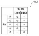
- FIG. 10 is a diagram showing an example of a table TBL3 according to the present modification.
- the table TBL3 is also stored in the internal memory 55, like the tables TBL1 and TBL2.
- FIG. 10 is a diagram illustrating an example of a table TBL3 for determining whether the brightness correction of an endoscope image is performed by controlling the laser diode 41 or by performing image processing.
- the table TBL3 uses either the control of the laser diode 41 (hereinafter, also referred to as LD control) or the image processing according to the higher one of the temperature T1 of the laser diode 41 and the temperature T2 of the photodiode 43. Stipulates whether the brightness of the endoscope image is corrected.
- the higher one of the temperature T1 of the laser diode 41 and the temperature T2 of the photodiode 43 is used as a reference, but the average value of the temperature T1 of the laser diode 41 and the temperature T2 of the photodiode 43 is used.
- a predetermined one of the temperature T1 of the laser diode 41 and the temperature T2 of the photodiode 43 may be used as a reference.
- Each temperature t1, t2, t3, t4, and t5 of the table TBL3 shown in FIG. 10 defines a temperature range as in FIG.
- the brightness correction of the endoscope image is performed by controlling the laser diode 41 (LD control). It is set in the table TBL3 that the brightness correction of the endoscope image is performed by image processing when the temperature is at t5.
- FIG. 11 is a flowchart illustrating an example of the flow of the temperature correction processing of the light quantity emitted from the light emitting unit 33 according to the present modification.
- the same processes as those in FIG. 9 are denoted by the same step numbers, and description thereof is omitted. Only different processes will be described.
- the detected light amount temperature correction circuit 54 determines whether the brightness correction of the endoscope image is performed by LD control based on the table TBL3 (S10). Specifically, whether the brightness correction of the endoscope image is performed by LD control based on the higher one of the temperature T1 of the laser diode 41 and the temperature T2 of the photodiode 43 with reference to the table TBL3. Is determined.
- LD If the higher of the temperature T1 of the laser diode 41 and the temperature T2 of the photodiode 43 is between t1 and t4, LD control is selected, and if it is at t5, image processing is selected.
- the detected light amount temperature correction circuit 54 executes the processing of S8.
- the detected light amount temperature correction circuit 54 outputs the difference data calculated in S7 to the control unit 61 as indicated by a dotted line in FIG.
- the data is transmitted from the unit 62 to the main unit 3 (S11).
- the wireless communication unit 72 transmits the difference data to the image processing circuit 73 via the control unit 71.
- the image processing circuit 73 determines the gain according to the received difference data, and corrects the brightness of the endoscope image by multiplying each pixel value of the endoscope image by the gain (S10).
- the temperature of the operation unit 12 held by the user increases. Therefore, if the higher one of the temperature T1 of the laser diode 41 and the temperature T2 of the photodiode 43 becomes t5 or more, the brightness of the image is adjusted by image processing so that the temperature of the operation unit 12 does not become more than the predetermined temperature. Therefore, it is possible to prevent the operation unit 12 held by the user from becoming hot.
- the LD control circuit 32 controls the light source so that either one of the temperatures does not exceed the predetermined temperature t5. To control the drive of. Then, when at least one of the temperature T1 and the temperature T2 becomes equal to or higher than the predetermined temperature t5, the image processing circuit 73 increases the brightness of the image.
- the brightness of the endoscope image may be appropriately controlled using the image processing.
- the brightness of the endoscope image is corrected by adjusting the emission light amount of the illumination light in consideration of the temperature characteristic of the optical sensor that detects the light amount of the illumination light.
- the emission light amount of the illumination light is adjusted in consideration of the temperature characteristics of the wavelength of the illumination light.
- the configuration of the endoscope system according to the second embodiment is substantially the same as the configuration of the endoscope system 1 according to the first embodiment shown in FIGS. 1 to 4, the same components are the same. The description will be omitted using the reference numerals, and only different components will be described.
- a distal end unit 47 is provided in the distal end portion 13 of the insertion section 11.
- a phosphor 47c that fluoresces when receiving laser light is arranged.
- the phosphor 47c has a characteristic that the fluorescence intensity changes depending on the wavelength band of the laser light as the excitation light. Since the illumination light emitted from the illumination window of the distal end portion 13 is a mixed color of blue laser light and yellow fluorescent light, if the temperature T1 of the laser diode 41 changes and the wavelength of the laser light shifts, the fluorescent light The intensity also changes, and the spectral shape of the illumination light also changes.
- FIG. 12 is a graph showing an example of the spectrum of the illumination light.
- the illumination light includes the blue laser light of the laser diode 41 and the yellow fluorescence of the phosphor 47c, and the peak wavelength of the laser light of the laser diode 41 fluctuates depending on the temperature as indicated by the dotted line L1.
- the fluorescence component in the illumination light also changes according to the wavelength change of the laser light.
- the color of the endoscope image also changes.
- the tables TBL1, TBL4, and TBL5 are stored in the internal memory 55.
- the table TBL1 is the table shown in FIG.
- FIG. 13 is a diagram illustrating an example of a table TBL4 in which the peak wavelength of the laser diode 41 is determined according to the temperature.
- Table TBL4 is also stored in internal memory 55.
- the table TBL4 stores the peak wavelength ⁇ of the laser diode 41 corresponding to the temperature T1.
- Each of the temperatures t1, t2, t3, and t4 in the table TBL4 shown in FIG. 13 defines a temperature range as in FIG.
- the table TBL4 is a table in which the peak wavelength ⁇ according to the temperature of the laser diode 41 is set.
- FIG. 14 is a diagram illustrating an example of a table TBL5 in which the sensitivity coefficient of the photodiode 43 is determined.
- the table TBL5 stores the sensitivity coefficient K of the photodiode 43 according to the temperature T2 of the photodiode 43 and the peak wavelength ⁇ .
- the sensitivity coefficient K of the photodiode 43 varies depending on the temperature T2 of the photodiode 43 and also varies depending on the peak wavelength.
- each peak wavelength ⁇ 1, ⁇ 2, ⁇ 3, ⁇ 4 of the table TBL5 defines a range of the peak wavelength of the illumination light.
- the light reception coefficient K23 is a light reception coefficient when the temperature T2 of the photodiode 43 is in the range of the temperature t2 and the peak wavelength is in the range of ⁇ 3.
- the table TBL5 is a table in which the temperature T2 of the photodiode 43 and the light receiving coefficient according to the peak wavelength ⁇ of the illumination light are set.
- the temperature correction of the emitted light amount in the drive control of the laser diode 41 will be described.
- the process of correcting the temperature of the emitted light amount of the light emitting unit 33 is the same as the process of FIG. 9 described above, and thus the process of the detected light amount temperature correction circuit 54 will be described with reference to FIG.
- the drive current value as the drive condition of the laser diode 41 is i2 Is selected (S1).
- the peak wavelength of the laser light is ⁇ 1.
- the laser diode 41 is driven by the drive current i2.
- the detected light amount temperature correction circuit 54 detects the temperature T1 (S2) of the laser diode 41 by the thermistor 44, the emitted light amount (S3) of the laser diode 41 by the photodiode 43, and the temperature T2 of the photodiode 43 by the thermistor 45 (S4). ).
- the detected light temperature correction circuit 54 extracts the sensitivity coefficient K from the tables TBL4 and TBL5 based on the temperature T1 of the laser diode 41 and the temperature T2 of the photodiode 43 (S11). For example, if the temperature T1 of the laser diode 41 is t2, ⁇ 2 is extracted from the table TBL4 as the peak wavelength. When the temperature T2 of the photodiode 43 is the temperature t3, the sensitivity coefficient K32 is extracted from the table TBL5 based on the extracted ⁇ 2 and the temperature t3.
- the detected light amount temperature correction circuit 54 uses the extracted sensitivity coefficient K to perform temperature correction on the detected light amount detected by the photodiode 43 (S6). That is, the detected light amount temperature correction circuit 54 corrects the amount of light received by the photodiode 43 in consideration of the wavelength of the illumination light corresponding to the temperature T1 of the laser diode 41. Specifically, the detected light amount temperature correction circuit 54 includes a table TBL4 for storing peak wavelength data of illumination light corresponding to the temperature T1 of the laser diode 41, and sensitivity data corresponding to the temperature T2 and the peak wavelength ⁇ of the photodiode 43. Is corrected using the table TBL5 that stores
- the LD control circuit 32 calculates an LD output estimated value ESO of the emitted light amount from the detected light amount LM after the temperature correction, and calculates a difference between the calculated LD output estimated value ESO and the LD output set value SSO. (S7).
- the LD control circuit 32 corrects the light amount drive signal DD based on the difference calculated in S7 (S8).
- the LD control circuit 32 refers to the table TBL1 and corrects the drive signal DD in the drive condition in the table TBL1 such that the difference becomes 0 in accordance with the calculated difference and the temperature T1. .
- the LD control circuit 32 outputs the drive signal DD based on the corrected light amount signal LM. Light is emitted.
- the emission light amount of the illumination light is adjusted in consideration of the temperature characteristics of the wavelength.
- the endoscope system that can appropriately control the amount of light emitted from the light source even when the temperatures of the light source and the optical sensor change. Furthermore, since the light amount of the light source is adjusted in consideration of the wavelength shift of the laser diode 41 due to the temperature, the brightness of the obtained endoscope image is also appropriate.
- the brightness of the endoscope image is appropriately controlled by the emission light amount of the illumination light.
- image processing is also used based on the temperature of at least one of the laser diode 41 and the photodiode 43. Then, the brightness and color of the endoscope image may be controlled.
- Tables TBL6 and TBL7 are stored in a memory (not shown) of the main body 3.
- FIG. 15 is a diagram illustrating an example of a table TBL6 for correcting a difference in light amount according to a modification of the second embodiment.
- the table TBL6 is a table in which gain coefficients according to the peak wavelength of the illumination light are set. Each wavelength ⁇ 1, ⁇ 2, ⁇ 3, ⁇ 4 of the table TBL6 shown in FIG. 15 defines the range of the peak wavelength.
- the gain coefficients G1, G2, G3, G4 are stored in the table TBL6 corresponding to the four wavelengths ⁇ 1, ⁇ 2, ⁇ 3, ⁇ 4.
- FIG. 16 is a diagram illustrating an example of a table TBL7 for correcting a difference in the wavelength of illumination light according to a modification of the second embodiment.
- the table TBL7 is a table in which a white balance coefficient according to the peak wavelength of the illumination light is set.
- the wavelengths ⁇ 1, ⁇ 2, ⁇ 3, and ⁇ 4 of the table TBL6 shown in FIG. 16 define the range of the peak wavelength similarly to FIG.
- B1, B2, B3, and B4 are set as B / G (blue / green), and R1, R2 as R / G (red / green).
- R3, R4 are stored in the table TBL7.
- the temperature correction processing of the emitted light amount of the light emitting unit 33 in the present modified example has the same flow as the processing of FIG. 11 described above, the processing of the detected light amount temperature correction circuit 54 will be described with reference to FIG. For the same processing as in the first and second embodiments, the description will be simplified, and only the different processing will be described.
- the detected light amount temperature correction circuit 54 calculates a difference s1 between the LD output estimated value ESO calculated in S6 and the LD output set value SSO, and sets the peak wavelength set value.
- the difference s2 from the estimated value is also calculated (S7).
- the detected light amount temperature correction circuit 54 determines whether the brightness correction of the endoscope image is performed by LD control based on the table TBL3 (S9). If the higher of the temperature T1 of the laser diode 41 and the temperature T2 of the photodiode 43 is between t1 and t4, LD control is selected, and if it is at t5, image processing is selected.
- the detected light amount temperature correction circuit 54 executes the process of S8. If it is determined to be performed by the image processing, the detected light amount temperature correction circuit 54 outputs the calculated difference data s1 and s2 to the control unit 61 as shown by a dotted line in FIG. The difference data s1 and s2 are transmitted from the image acquisition device 24 to the main unit 3 (S10).
- the difference data is transmitted from the wireless communication unit 72 of the main unit 3 to the image processing circuit 73 via the control unit 71.
- the image processing circuit 73 calculates a gain adjustment amount such that the received difference s1 becomes 0 from the difference between the gain coefficients between the wavelengths in the table TBL6 in FIG. 15, and adjusts the gain for each pixel value of the endoscope image.
- the brightness of the endoscopic image is corrected by adding the amounts.
- the image processing circuit 73 further calculates a white balance adjustment amount such that the received difference s2 becomes 0 from the difference of the white balance coefficient between the wavelengths in the table TBL7 of FIG.
- the color of the endoscope image is corrected by adding the white balance adjustment amount to the value.
- the LD control circuit 32 controls the light source so that either one of the temperatures does not exceed the predetermined temperature t5. To control the drive of.
- the image processing circuit 73 increases the luminance of the image and adjusts the color of the image.
- the brightness and color of the endoscope image may be appropriately adjusted by using the image processing.
Landscapes
- Health & Medical Sciences (AREA)
- Life Sciences & Earth Sciences (AREA)
- Physics & Mathematics (AREA)
- Surgery (AREA)
- Optics & Photonics (AREA)
- Engineering & Computer Science (AREA)
- Medical Informatics (AREA)
- General Health & Medical Sciences (AREA)
- Pathology (AREA)
- Nuclear Medicine, Radiotherapy & Molecular Imaging (AREA)
- Biomedical Technology (AREA)
- Heart & Thoracic Surgery (AREA)
- Biophysics (AREA)
- Molecular Biology (AREA)
- Animal Behavior & Ethology (AREA)
- Radiology & Medical Imaging (AREA)
- Public Health (AREA)
- Veterinary Medicine (AREA)
- General Physics & Mathematics (AREA)
- Condensed Matter Physics & Semiconductors (AREA)
- Electromagnetism (AREA)
- Astronomy & Astrophysics (AREA)
- Signal Processing (AREA)
- Multimedia (AREA)
- Endoscopes (AREA)
- Instruments For Viewing The Inside Of Hollow Bodies (AREA)
Abstract
内視鏡システム1は、光量制御可能な内視鏡用のレーザダイオード41により照明光を出射する光源装置23と、照明光の反射光を受光して得られた撮像信号を受信することによって画像を取得する画像取得装置24と、レーザダイオード41の照明光の一部を受光するフォトダイオード43と、レーザダイオード41の温度T1を検出するサーミスタ44と、フォトダイオード43の温度T2を検出するサーミスタ45と、温度T2に基づいて、フォトダイオード43の受光量を補正する検出光量温度補正回路54と、検出光量温度補正回路54より補正された補正後の受光量LMと温度T1に基づいて、照明光の光量が設定値になるようにレーザダイオード41の駆動を制御するレーザダイオード制御回路32と、を有する。
Description
本発明は、内視鏡システムに関する。
内視鏡が、医療分野及び工業分野で広く用いられている。例えば、内視鏡は、細長の挿入部を有し、その挿入部の先端部の照明窓から照明光を照射し、被写体からの照明光の反射光が先端部の観察窓に入射する。内視鏡システムは、照明光を出射する光源を有しており、光源から出射する照明光の光量は、内視鏡画像が所望の明るさになるように制御される。
一般に、光源の出射光の光量は、出射光の一部を受光する受光素子の出力に基づいて制御される。例えば、日本国特開2012-94891号公報には、レーザ光が照射される位置に光センサを設けて、半導体レーザチップの光出力を制御する技術が開示されている。
また、光源の温度が変化すると、光源からの出射光の光量と波長も変化するため、例えば、日本国特開2017-207412号公報には、光源が発する光の光量を検出する光センサと、光源の温度を検出する温度検出機構を有し、光源の温度が変化した場合であっても、光源の輝度及び色度を一定に維持する技術が開示されている。よって、これらの技術は、内視鏡システムに適用することも考えられる。
しかし、光源の出射光の光量を光センサで検出したとしても、光センサ自体も温度特性を有するため、光源の出射光の光量は、適切に制御することはできない。光源の出射光の光量が適切に制御することはできなければ、表示装置に表示される内視鏡画像は、適切な明るさにならない。
よって、本発明は、光源及び光センサの温度が変化した場合でも、光源の出射光の光量を適切に制御できる内視鏡システムを提供することを目的とする。
本発明の一態様の内視鏡システムは、光量制御可能な内視鏡用の光源により照明光を出射する光源装置と、前記照明光の反射光を受光して得られた撮像信号を受信することによって画像を取得する画像取得装置と、前記光源の前記照明光の一部を受光する受光素子と、前記光源の第1の温度を検出する第1の温度センサと、前記受光素子の第2の温度を検出する第2の温度センサと、前記第2の温度に基づいて、前記受光素子の受光量を補正する受光量補正部と、前記受光量補正部より補正された補正後の受光量と前記第1の温度に基づいて、前記照明光の光量が設定値になるように前記光源の駆動を制御する駆動制御部と、を有する。
以下、本発明の実施の形態について説明する。
(第1の実施の形態)
(構成)
図1は、本発明の実施の形態に係わる内視鏡システムの構成図である。
(第1の実施の形態)
(構成)
図1は、本発明の実施の形態に係わる内視鏡システムの構成図である。
内視鏡システム1は、内視鏡2と、本体部3と、表示部4とを有して構成される。内視鏡2と本体部3は、二点鎖線で示すように、無線により互いに通信が可能となっている。本体部3と表示部4は、図示しない信号ケーブルにより接続されている。
内視鏡2は、細長の挿入部11と、操作部12を有している。挿入部11は、先端から、順に、先端部13、湾曲部14及び可撓管部15を有している。可撓管部15の基端は、操作部12に接続されている。
操作部12は、湾曲操作レバー16及び各種操作ボタン17を有している。内視鏡2のユーザは、操作部12を把持し、湾曲操作レバー16を操作することにより、湾曲部14を所望の方向に湾曲させることができる。
また、ユーザは、各種操作ボタン17を操作することにより、内視鏡画像をフリーズさせたり、フリーズした静止画を、本体部3の記憶装置に記録したりすることができる。
先端部13には、観察窓と照明窓が設けられており、照明窓から照明光ILが被写体Sに出射され、被写体Sからの照明光ILの反射光RLが観察窓に入射する。反射光RLは、撮像光学系を通り、先端部13内の撮像素子48(図2)の受光面に結像する。撮像素子48からの撮像信号は、無線により、本体部3に送信される。内視鏡2からの撮像信号に基づいて生成された内視鏡画像は、表示部4に表示される。
なお、ここでは、内視鏡2がバッテリ駆動され、内視鏡2と本体部3は、無線により互いに通信するように構成されているが、点線で示すように、内視鏡2と本体部3は、ケーブル5により接続されていてもよい。その場合、内視鏡2への電源の供給は、ケーブル5を介して行われ、内視鏡2と本体部3の通信もケーブル5内の信号線を介して行われる。
図2は、内視鏡システム1の構成を示すブロック図である。
内視鏡2は、二次電池などのバッテリ21と、電源回路22を有している。電源回路22は、バッテリ21からの電力を受けて、内視鏡2内の各回路が必要とする各種電圧を発生し、各回路へ供給する。
内視鏡2は、二次電池などのバッテリ21と、電源回路22を有している。電源回路22は、バッテリ21からの電力を受けて、内視鏡2内の各回路が必要とする各種電圧を発生し、各回路へ供給する。
内視鏡2は、光源装置23と、画像取得装置24をさらに有している。
バッテリ21、電源回路22、光源装置23及び画像取得装置24は、内視鏡2の操作部12内に設けられている。
バッテリ21、電源回路22、光源装置23及び画像取得装置24は、内視鏡2の操作部12内に設けられている。
光源装置23は、動作モード選択回路31と、レーザダイオード制御回路(以下、LD制御回路という)32と、発光部33と、検出光量温度補正部34とを含んでいる。発光部33は、光量制御可能な光源を有する。すなわち、光源装置23は、光量制御可能な内視鏡用の光源により照明光を出射する。
動作モード選択回路31は、ユーザの操作に応じた指示信号を、LD制御回路32へ出力する。ユーザは、各種操作ボタン17を操作することにより、各種コマンドを内視鏡2に与えることができる。動作モード選択回路31は、そのコマンド信号に応じた指示信号を、レーザダイオード制御回路32と、後述する制御部61へ出力する回路である。例えば、動作モード選択回路31から出力される指示信号には、白色光による通常観察モードの選択信号が含まれる。
LD制御回路32は、プロセッサを含み、プロセッサは、中央処理装置(CPU)、ROM、RAMを含む。LD制御回路32は、照明光の光量を示す光量信号LMを検出光量温度補正部34から受信する。後述するように、LD制御回路32は、レーザダイオード41の温度T1と光量信号LMに基づいて、照明光の光量が設定値になるように発光部33の光源の駆動を制御する駆動信号DDを出力する駆動制御部を構成する。すなわち、駆動信号DDは、検出光量温度補正部34からの光量信号LMに基づいて決定される。
後述するように、検出光量温度補正回路54は、サーミスタ45により検出されたフォトダイオード43の温度に基づいて、フォトダイオード43の受光量を補正した光量信号LMを出力する受光量補正部を構成する。
後述するように、検出光量温度補正回路54は、サーミスタ45により検出されたフォトダイオード43の温度に基づいて、フォトダイオード43の受光量を補正した光量信号LMを出力する受光量補正部を構成する。
また、LD制御回路32は、動作モード選択回路31からの指示信号及び制御部61からの制御信号に応じて動作する。例えば、動作モードが通常観察モードが選択されているとき、LD制御回路32は、制御部61からの調光レベルに応じた駆動信号DDを生成する。
発光部33は、半導体発光素子であるレーザダイオード(LD)41と、集光レンズ42と、光センサとしてのフォトダイオード(PD)43を内蔵する。フォトダイオード43は、内視鏡2の操作部12内、又は操作部12の近傍部分内に設けられる。
光源であるレーザダイオード41には、サーミスタ44が設けられている。サーミスタ44は、光源であるレーザダイオード41の温度を検出する温度センサであり、レーザダイオード41が搭載された基板上において、レーザダイオード41の近傍に設けられる。すなわち、サーミスタ44は、レーザダイオード41と熱的に接続されている。
フォトダイオード43には、サーミスタ45が設けられている。サーミスタ45は、発光部33に設けられ、受光素子であるフォトダイオード43の温度を検出する温度センサであり、フォトダイオード43に密着してあるいは近傍に設けられる。すなわち、サーミスタ45は、フォトダイオード43と熱的に接続されている。サーミスタ45の取り付け構造については、後述する。
レーザダイオード41は、レーザダイオード制御回路32からの駆動電流である駆動信号DDに応じて発光する。
集光レンズ42は、レーザダイオード41からのレーザ光を集光して、発光部33に接続された光ファイバ46の基端部の端面に集光する。光ファイバ46の基端部の端面に入射した光は、照明光として、光ファイバ46内を通って、光ファイバ46の先端部の端面から出射する。
なお、一般に、先端部13の2つの照明窓から照明光が出射するように、光ファイバ46は、途中で2分岐しているが、ここでは、その分岐は、省略し図示していない。
集光レンズ42からの光は光ファイバ46の基端部の端面に集光されるが、フォトダイオード43は、その光ファイバ46の基端部の端面において反射した光を受光できる位置に配設される。すなわち、フォトダイオード43は、光源であるレーザダイオード41の照明光の一部を受光するように、発光部33に設けられた受光素子である。フォトダイオード43が受光する光の光量は、レーザダイオード41が出射するレーザ光の光量に比例する。
以上のように、内視鏡2は、照明光を導光するための光ファイバ46を有し、受光素子であるフォトダイオード43は、光ファイバ46の照明光の入射端の近傍に配置されている。
以上のように、内視鏡2は、照明光を導光するための光ファイバ46を有し、受光素子であるフォトダイオード43は、光ファイバ46の照明光の入射端の近傍に配置されている。
発光部33と光ファイバ46とは、ピグテイル型構造を有し、発光部33と光ファイバ46は一体に形成されている。よって、光ファイバ46は、発光部33から延出している。
図3は、フォトダイオード43の取り付け構造を示す部分断面図である。
発光部33は、レーザダイオード41やレンズ42などを保持するためのハウジング33aを有している。開口部33bが、発光部33のハウジング33aに設けられている。フレキシブル基板33cが、開口部33bを覆うように接着剤33dによりハウジング33aに固定されている。フォトダイオード43とサーミスタ45が、フレキシブル基板33cを挟むように、それぞれフレキシブル基板33cの裏面と表面上に搭載されている。
発光部33は、レーザダイオード41やレンズ42などを保持するためのハウジング33aを有している。開口部33bが、発光部33のハウジング33aに設けられている。フレキシブル基板33cが、開口部33bを覆うように接着剤33dによりハウジング33aに固定されている。フォトダイオード43とサーミスタ45が、フレキシブル基板33cを挟むように、それぞれフレキシブル基板33cの裏面と表面上に搭載されている。
フォトダイオード43は、ハウジング33a内に配置される。すなわち、サーミスタ45がフレキシブル基板33cを通してフォトダイオード43の温度を正確に検出できるように、フォトダイオード43とサーミスタ45は、回路基板であるフレキシブル基板33cを挟んでフレキシブル基板33c上に搭載されている。
フォトダイオード43の出力信号及びサーミスタ45の出力信号は、フレキシブル基板33cに接続された複数の信号線33eを通して、それぞれ光量検出回路53と温度検出回路52に供給される。
図2に戻り、光ファイバ46は、挿入部11内に挿通されている。上述したように、光ファイバ46の基端部は、発光部33に接続されるが、光ファイバ46の先端部は、先端部13内に設けられた先端ユニット47に接続される。内視鏡2の先端ユニット47は、蛍光体を有し、先端部13の照明窓(図示せず)の後ろ側に配設される。
図4は、先端ユニット47の構成図である。
先端ユニット47は、ホルダ47aと、透明部材47bと、蛍光体47cを有する。蛍光体47cには、図示しないが拡散粒子が含まれている。
先端ユニット47は、ホルダ47aと、透明部材47bと、蛍光体47cを有する。蛍光体47cには、図示しないが拡散粒子が含まれている。
ホルダ47aは、部分円錐形状あるいはテーパ形状の内周面47dを有し、内周面上には、銀蒸着による反射膜が形成されている。
光ファイバ46の先端部の端面からの光が透明部材47b内に照射されるように、光ファイバ46の先端部がホルダ47aに接続されている。
光ファイバ46の先端部の端面からの光が透明部材47b内に照射されるように、光ファイバ46の先端部がホルダ47aに接続されている。
光ファイバ46から透明部材47b内に入射した光は直進すると共に、拡散した光が内周面47dで反射した後、蛍光体47cに入射する。蛍光体47cは、受けた光に応じて蛍光することにより、光の波長変換を行う。
内周面47dは、蛍光体47cが発した光の一部を反射して、光ファイバ46の先端面から出射した光と蛍光体47cが発した光は混合して、先端ユニット47の先端部から出射する。
ここでは、通常観察のための白色光が、照明光として被写体に照射される。そのため、レーザダイオード41は、青色のレーザ光を出射する。蛍光体47cは、黄色の蛍光体であり、青色のレーザ光を受けて励起されて黄色の蛍光を発する。その結果、青色の拡散光と黄色の蛍光の混合光が、白色光となって 照明窓から出射する。
すなわち、内視鏡2は、光源から出射された光の一部を波長変換する蛍光体47cを有し、照明光は、光源から出射された光と、波長変換された光の混合光である。
すなわち、内視鏡2は、光源から出射された光の一部を波長変換する蛍光体47cを有し、照明光は、光源から出射された光と、波長変換された光の混合光である。
なお、図2において、点線で示すように、フォトダイオード43とサーミスタ45は、先端ユニット47の近傍に配置してもよい。すなわち、光ファイバ46の先端部の端面から出射した光の一部を受光するように、フォトダイオード43を先端部13に配設してもよい。
図2に戻り、挿入部11の先端部13内には、撮像素子48が配置されている。図示しない撮像光学系が、先端部13の観察窓の後ろ側に配設され、撮像素子48は、撮像光学系を通った光を受光する位置に配設される。撮像素子48は、例えばCMOSイメージセンサである。
検出光量温度補正部34は、温度検出回路51、52と、光量検出回路53と、検出光量温度補正回路54と、内部メモリ55と、を含む。
温度検出回路51は、サーミスタ44と接続されており、レーザダイオード41の温度を検出し、検出した温度の信号を出力する。
温度検出回路51は、サーミスタ44と接続されており、レーザダイオード41の温度を検出し、検出した温度の信号を出力する。
温度検出回路52は、サーミスタ45と接続されており、フォトダイオード43の温度を検出し、検出した温度の信号を出力する。
光量検出回路53は、フォトダイオード43と接続されており、フォトダイオード43が受ける光の光量を検出し、検出した光量の信号を出力する。
光量検出回路53は、フォトダイオード43と接続されており、フォトダイオード43が受ける光の光量を検出し、検出した光量の信号を出力する。
検出光量温度補正回路54は、プロセッサを含み、プロセッサは、中央処理装置(CPU)、ROM、RAMを含む。検出光量温度補正回路54は、光量検出回路53からの光量信号を、温度検出回路52からの温度信号に基づいて、内部メモリ55に格納されている各種テーブルデータを用いて、温度補正した光量信号LMを出力する。
検出光量温度補正回路54における、光量信号LMの生成処理については後述する。
内部メモリ55は、後述する各種データを格納するテーブルが格納されている。
内部メモリ55は、後述する各種データを格納するテーブルが格納されている。
画像取得装置24は、撮像素子48からの撮像信号を受信する制御部61と、無線通信部62を含む。画像取得装置24は、照明光の反射光を受光して得られた撮像信号を受信することによって画像を取得する。
具体的には、制御部61は、撮像素子48からの撮像信号を受信して、撮像信号を圧縮する回路である。制御部61は、圧縮した撮像信号を無線通信部62へ出力する。
具体的には、制御部61は、撮像素子48からの撮像信号を受信して、撮像信号を圧縮する回路である。制御部61は、圧縮した撮像信号を無線通信部62へ出力する。
また、制御部61は、受信した撮像信号に基づく調光処理等も行う。
無線通信部62は、所定の周波数帯域を利用した無線通信を行うための回路である。無線通信部62は、圧縮された撮像信号を本体部3へ送信する。
無線通信部62は、所定の周波数帯域を利用した無線通信を行うための回路である。無線通信部62は、圧縮された撮像信号を本体部3へ送信する。
本体部3は、制御部71と、無線通信部72と、画像処理回路73を有する。
制御部71は、プロセッサを含み、プロセッサは、中央処理装置(CPU)、ROM、RAMを含む。
制御部71は、プロセッサを含み、プロセッサは、中央処理装置(CPU)、ROM、RAMを含む。
無線通信部72は、内視鏡2の無線通信部62と通信する回路である。無線通信部72は、無線通信部62からの撮像信号の無線信号を受信し、制御部71へ出力する。受信した撮像信号は圧縮されているので、制御部71は、受信した撮像信号を伸長して、画像処理回路73へ出力する。
画像処理回路73は、ガンマ補正などの各種画像処理を施して、表示信号を生成する。表示信号は、表示部4へ出力される。
ユーザは、通常観察モードを選択すると、挿入部11の先端部13から白色の照明光ILが被写体に照射され、被写体から反射光RLによる被写体像が撮像素子48の撮像面に結像する。撮像素子48で得られた撮像信号は圧縮され、圧縮された撮像信号が無線により、内視鏡2から本体部3へ送信される。
ユーザは、通常観察モードを選択すると、挿入部11の先端部13から白色の照明光ILが被写体に照射され、被写体から反射光RLによる被写体像が撮像素子48の撮像面に結像する。撮像素子48で得られた撮像信号は圧縮され、圧縮された撮像信号が無線により、内視鏡2から本体部3へ送信される。
本体部3は、無線で受信した撮像信号を伸長し、伸長された撮像信号に対して画像処理を行い、画像処理された内視鏡画像の画像信号を表示部4に出力する。よって、ユーザは、表示部4に表示される内視鏡画像を見て、内視鏡検査などを行うことができる。
ここで、レーザダイオード41の温度特性を説明する。図5は、レーザダイオード41の温度特性を示す図である。
図5に示すように、レーザダイオード41の出射光量は、レーザダイオード41の駆動電流に比例して増加する。実線は、レーザダイオード41の温度がTaのときの、駆動電流と出射光量の関係を示し、点線は、レーザダイオード41の温度が、Taよりも高いTbのときの、駆動電流と出射光量の関係を示している。ここでは、レーザダイオード41の温度が高くなると、出射光量は低下することが示されている。よって、レーザダイオード41の出射光量は、温度特性を有する。
図5に示すように、レーザダイオード41の出射光量は、レーザダイオード41の駆動電流に比例して増加する。実線は、レーザダイオード41の温度がTaのときの、駆動電流と出射光量の関係を示し、点線は、レーザダイオード41の温度が、Taよりも高いTbのときの、駆動電流と出射光量の関係を示している。ここでは、レーザダイオード41の温度が高くなると、出射光量は低下することが示されている。よって、レーザダイオード41の出射光量は、温度特性を有する。
図6は、フォトダイオード43の温度特性を説明する。図6は、フォトダイオード43の相対感度の温度特性を示す図である。
図6に示すように、フォトダイオード43の相対感度は、フォトダイオード43の周囲温度に比例して増加する。すなわち、フォトダイオード43の周囲温度の増加に比例して、フォトダイオード43の相対感度が増加する。さらに、相対感度は、受光する光の波長によっても異なっている。図6の実線と点線は、波長が異なる光に対する、周囲温度の変化に対する、相対感度の変化を示している。よって、フォトダイオード43の相対感度は、温度特性を有する。
図6に示すように、フォトダイオード43の相対感度は、フォトダイオード43の周囲温度に比例して増加する。すなわち、フォトダイオード43の周囲温度の増加に比例して、フォトダイオード43の相対感度が増加する。さらに、相対感度は、受光する光の波長によっても異なっている。図6の実線と点線は、波長が異なる光に対する、周囲温度の変化に対する、相対感度の変化を示している。よって、フォトダイオード43の相対感度は、温度特性を有する。
また、レーザダイオード41とフォトダイオード43が離間して配置されている場合、レーザダイオード41の温度変化とフォトダイオード43の温度変化は、一致しない。
(作用)
内視鏡システム1では、照明光の光量が設定値になるように、光源の駆動が制御される。照明光の光量は、フォトダイオード43により検出されるが、フォトダイオード43の検出光量は、温度特性を有するため、照明光の検出光量の温度補正が行われる。
(作用)
内視鏡システム1では、照明光の光量が設定値になるように、光源の駆動が制御される。照明光の光量は、フォトダイオード43により検出されるが、フォトダイオード43の検出光量は、温度特性を有するため、照明光の検出光量の温度補正が行われる。
フォトダイオード43による照明光の検出光量の温度補正について説明する。
はじめに、その検出光量の温度補正に用いられるテーブルデータについて説明する。
はじめに、その検出光量の温度補正に用いられるテーブルデータについて説明する。
テーブルTBL1とTBL2は、内部メモリ55に格納される。
図7は、レーザダイオード41の駆動条件を定めたテーブルTBL1の例を示す図である。
図7は、レーザダイオード41の駆動条件を定めたテーブルTBL1の例を示す図である。
テーブルTBL1は、レーザダイオード41の温度T1とレーザダイオード41の駆動条件に応じたレーザダイオード41の出力値(以下、LD出力値という)すなわち出射光量値を格納している。レーザダイオード41の駆動条件は、例えば駆動電流値である。
レーザダイオード41の出射光の光量は、図5に示したように、レーザダイオード41の温度T1に応じて出射光量が変化する、すなわち、温度特性を有する。
図7に示すテーブルTBL1の各温度t1、t2、t3、t4は、レーザダイオード41の温度T1の範囲を規定している。同様に、テーブルTBL1の各駆動条件としてのi1、i2、i3、i4は、駆動条件の範囲、ここではレーザダイオード41の駆動電流の範囲を規定している。
例えば、図7において、LD出力値O23は、レーザダイオード41の温度T1が温度t2の範囲にあり、かつ駆動条件がi3の範囲にあるときの出射光量である。言い換えれば、レーザダイオード41の温度T1が温度t2であるとき、出射光量をO23にするためには、レーザダイオード41に駆動電流i3を供給する必要があることを、図7は示している。
よって、テーブルTBL1は、レーザダイオード41の温度T1と、レーザダイオード41の駆動条件に応じたLD出力値(すなわち出射光量値)が設定されたテーブルである。すなわち、テーブルTBL1は、所望の出射光量を得るための温度T1と駆動電流の関係を示している。
図8は、フォトダイオード43の感度係数を定めたテーブルTBL2の例を示す図である。
テーブルTBL2は、フォトダイオード43の温度T2に応じた感度係数Kを格納している。図8に示すテーブルTBL2の各温度t1、t2、t3、t4は、図7と同様に、温度範囲を規定している。
テーブルTBL2は、フォトダイオード43の温度T2に応じた感度係数Kを格納している。図8に示すテーブルTBL2の各温度t1、t2、t3、t4は、図7と同様に、温度範囲を規定している。
フォトダイオード43は、フォトダイオード43の温度T2に応じて感度係数Kが変化する。さらに、図6に示すように、フォトダイオード43の感度係数Kは、受光した光の波長によっても、異なる。
感度係数は、温度に応じた、フォトダイオード43の感度の変化量あるいは変化率を示す感度データである。よって、テーブルTBL2は、フォトダイオード43の温度T2に応じたフォトダイオード43の感度データを格納する。
感度係数は、温度に応じた、フォトダイオード43の感度の変化量あるいは変化率を示す感度データである。よって、テーブルTBL2は、フォトダイオード43の温度T2に応じたフォトダイオード43の感度データを格納する。
よって、テーブルTBL2は、フォトダイオード43の温度に応じた感度係数Kが設定されたテーブルである。
次に、レーザダイオード41の駆動制御における、出射光量の温度補正について説明する。
図9は、発光部33の出射光量の温度補正と光源の駆動制御の処理の流れの例を示すフローチャートである。
次に、レーザダイオード41の駆動制御における、出射光量の温度補正について説明する。
図9は、発光部33の出射光量の温度補正と光源の駆動制御の処理の流れの例を示すフローチャートである。
図9の処理は、検出光量温度補正回路54とLD制御回路32において実行される。ここでは、検出光量温度補正回路54及びLD制御回路32のCPUがROMのプログラムを読み出して実行することによって、図9の処理は実行される。
LD制御回路32は、レーザダイオード41のLD出力値(すなわち出射光量値)が、LD出力設定値SSOになるように、駆動条件(すなわち駆動電流値)を決定する(ステップ(以下、Sと略す)1)。LD制御回路32は、テーブルTBL1を参照して、レーザダイオード41の温度T1に基づいて、駆動電流値を決定する。
例えば、レーザダイオード41の温度T1が仮に温度t1で、出射光量のLD出力設定値SSOがO12であるとき、レーザダイオード41の駆動条件である駆動電流値は、i2が選択される。
その結果、S1で決定した駆動条件によりレーザダイオード41は駆動される。
その結果、S1で決定した駆動条件によりレーザダイオード41は駆動される。
検出光量温度補正回路54は、サーミスタ44によるレーザダイオード41の温度T1を検出する(S2)。
同時に、検出光量温度補正回路54は、フォトダイオード43によるレーザダイオード41の出射光量を検出する(S3)。
同時に、検出光量温度補正回路54は、フォトダイオード43によるレーザダイオード41の出射光量を検出する(S3)。
同時に、検出光量温度補正回路54は、サーミスタ45によるフォトダイオード43の温度T2を検出する(S4)。
検出光量温度補正回路54は、フォトダイオード43の温度T2に基づいて、テーブルTBL2から感度係数Kを抽出する(S5)。例えば、フォトダイオード43の温度T2が温度t3であるとき、感度係数Kは、K3が抽出される。
検出光量温度補正回路54は、フォトダイオード43の温度T2に基づいて、テーブルTBL2から感度係数Kを抽出する(S5)。例えば、フォトダイオード43の温度T2が温度t3であるとき、感度係数Kは、K3が抽出される。
検出光量温度補正回路54は、抽出した感度係数Kを用いて、フォトダイオード43により検出された検出光量を温度補正する(S6)。すなわち、検出光量温度補正回路54は、フォトダイオード43の温度T2に応じたフォトダイオード43の感度データを格納するテーブルTBL2を用いて、フォトダイオード43の受光量を補正する。
LD制御回路32は、温度補正された補正後の検出光量LMから、出射光量のLD出力推定値ESOを算出し、算出されたLD出力推定値ESOと、LD出力設定値SSOとの差分を算出する(S7)。
LD制御回路32は、S7で算出された差分に基づいて、光量の駆動信号DDを補正する(S8)。
LD制御回路32は、S7で算出された差分に基づいて、光量の駆動信号DDを補正する(S8)。
具体的には、LD制御回路32は、テーブルTBL1を参照して、テーブルTBL1における駆動条件を、算出された差分と温度T1に応じて、差分が0になるように、駆動信号DDを補正する。
すなわち、LD制御回路32は、補正後の受光量と設定値の差と、レーザダイオード41の温度T1とに基づいて、算出された差分が小さくなるように、レーザダイオード41を駆動する駆動信号DDを補正する。
すなわち、LD制御回路32は、補正後の受光量と設定値の差と、レーザダイオード41の温度T1とに基づいて、算出された差分が小さくなるように、レーザダイオード41を駆動する駆動信号DDを補正する。
その結果、LD制御回路32は、補正された光量信号LMに基づいて、駆動信号DDを出力するので、レーザダイオード41の温度特性及びフォトダイオード43の温度特性に応じて、適切な照明光量の照明光が出射される。
以上のようにして、上述した実施の形態によれば、光源及び光センサの温度が変化した場合でも、光源の出射光の光量を適切に制御できる内視鏡システムを提供することができる。
次に、本実施の形態の変形例について説明する。
上述した実施の形態では、照明光の出射光量により、内視鏡画像の明るさを適切に制御しているが、レーザダイオード41及びフォトダイオード43の少なくとも一方の温度に基づいて、画像処理も利用して、内視鏡画像の明るさを適切に制御するようにしてもよい。
上述した実施の形態では、照明光の出射光量により、内視鏡画像の明るさを適切に制御しているが、レーザダイオード41及びフォトダイオード43の少なくとも一方の温度に基づいて、画像処理も利用して、内視鏡画像の明るさを適切に制御するようにしてもよい。
図10は、本変形例に係わる、テーブルTBL3の例を示す図である。テーブルTBL3も、TBL1とTBL2と同様に、内部メモリ55に格納される。
図10は、内視鏡画像の明るさ補正を、レーザダイオード41の制御により行うか、画像処理により行うかの判定をするためのテーブルTBL3の例を示す図である。
テーブルTBL3は、レーザダイオード41の温度T1及びフォトダイオード43の温度T2のうち、高い方の温度に応じて、レーザダイオード41の制御(以下、LD制御ともいう)と、画像処理のいずれを用いて、内視鏡画像の明るさ補正を行うかを規定している。
なお、ここでは、レーザダイオード41の温度T1及びフォトダイオード43の温度T2のうち高い方の温度が、基準として用いられているが、レーザダイオード41の温度T1及びフォトダイオード43の温度T2の平均値、あるいはレーザダイオード41の温度T1及びフォトダイオード43の温度T2の予め決められたいずれか一方の温度、を基準として用いてもよい。
図10に示すテーブルTBL3の各温度t1、t2、t3、t4、t5は、図7と同様に、温度範囲を規定している。レーザダイオード41の温度T1及びフォトダイオード43の温度T2のうち高い方の温度がt1からt4の範囲内にあるとき、内視鏡画像の明るさ補正は、レーザダイオード41の制御(LD制御)により行われ、温度がt5にあるとき、内視鏡画像の明るさ補正は、画像処理により行われることが、テーブルTBL3に設定されている。
図11は、本変形例に係わる、発光部33の出射光量の温度補正処理の流れの例を示すフローチャートである。
なお、図9中の処理ステップと同じ処理については、同じステップ番号を付して説明は、省略し、異なる処理についてのみ説明する。
なお、図9中の処理ステップと同じ処理については、同じステップ番号を付して説明は、省略し、異なる処理についてのみ説明する。
S1からS8までの処理を実行後、検出光量温度補正回路54は、テーブルTBL3に基づいて、内視鏡画像の明るさ補正は、LD制御により行うかを判定する(S10)。具体的には、内視鏡画像の明るさ補正は、テーブルTBL3を参照して、レーザダイオード41の温度T1及びフォトダイオード43の温度T2のうち高い方の温度に基づいて、LD制御により行うかを判定する。
もしも、レーザダイオード41の温度T1及びフォトダイオード43の温度T2のうち高い方の温度が、t1からt4にあるときは、LD制御が選択され、t5にあるときは、画像処理が選択される。
LD制御により行うと判定されると(S9:YES)、検出光量温度補正回路54は、S8の処理を実行する。
画像処理により行うと判定されると(S9:NO)、検出光量温度補正回路54は、S7において算出された差分データを、図2において点線で示すように、制御部61へ出力し、無線通信部62から本体部3へ送信する(S11)。
本体部3では、無線通信部72は、制御部71を介して差分データを画像処理回路73へ伝達される。
画像処理回路73は、受信した差分データに応じた、ゲインを決定し、内視鏡画像の各画素値にゲインを乗算することによって、内視鏡画像の明るさを補正する(S10)。
画像処理回路73は、受信した差分データに応じた、ゲインを決定し、内視鏡画像の各画素値にゲインを乗算することによって、内視鏡画像の明るさを補正する(S10)。
レーザダイオード41などの熱源が操作部12内に配置されると、ユーザが把持する操作部12の温度が高くなる。そのため、操作部12が所定の温度以上にならないように、レーザダイオード41の温度T1及びフォトダイオード43の温度T2のうち高い方の温度がt5以上になると、画像処理により画像の明るさを調整するので、ユーザが把持する操作部12が熱くなるのを防止することができる。
以上のように、LD制御回路32は、温度T1又は温度T2の少なくともいずれか一方の温度が所定の温度t5以上になると、そのいずれか一方の温度が所定の温度t5を超えないように、光源の駆動を制御する。そして、画像処理回路73が、温度T1又は温度T2の少なくともいずれか一方の温度が所定の温度t5以上になると、画像の輝度を上げる。
以上のように、LD制御回路32は、温度T1又は温度T2の少なくともいずれか一方の温度が所定の温度t5以上になると、そのいずれか一方の温度が所定の温度t5を超えないように、光源の駆動を制御する。そして、画像処理回路73が、温度T1又は温度T2の少なくともいずれか一方の温度が所定の温度t5以上になると、画像の輝度を上げる。
以上のように、画像処理も利用して、内視鏡画像の明るさを適切に制御するようにしてもよい。
(第2の実施の形態)
第1の実施の形態は、照明光の光量を検出する光センサの温度特性を加味して、照明光の出射光量を調整することによって、内視鏡画像の明るさを補正しているが、第2の実施の形態では、照明光の波長の温度特性も加味して、照明光の出射光量を調整する。
(第2の実施の形態)
第1の実施の形態は、照明光の光量を検出する光センサの温度特性を加味して、照明光の出射光量を調整することによって、内視鏡画像の明るさを補正しているが、第2の実施の形態では、照明光の波長の温度特性も加味して、照明光の出射光量を調整する。
第2の実施の形態の内視鏡システムの構成は、図1から図4に示した第1の実施の形態の内視鏡システム1の構成と略同じであるので、同じ構成要素については同じ符号を用いて説明は省略し、異なる構成要素についてのみ説明する。
図2に示すように、内視鏡システム1において、挿入部11の先端部13内には、先端ユニット47が設けられている。先端ユニット47内には、レーザ光を受けると蛍光する蛍光体47cが配置されている。
蛍光体47cは、励起光であるレーザ光の波長帯域により蛍光強度が変化する特性を有している。
先端部13の照明窓から出射する照明光は、青色のレーザ光と、黄色の蛍光の混合色であるため、レーザダイオード41の温度T1が変化して、レーザ光の波長がシフトすると、蛍光の強度も変化して、照明光のスペクトル形状も変化してしまう。
先端部13の照明窓から出射する照明光は、青色のレーザ光と、黄色の蛍光の混合色であるため、レーザダイオード41の温度T1が変化して、レーザ光の波長がシフトすると、蛍光の強度も変化して、照明光のスペクトル形状も変化してしまう。
図12は、照明光のスペクトルの例を示すグラフである。
照明光は、レーザダイオード41の青色のレーザ光と、蛍光体47cの黄色の蛍光を含むが、レーザダイオード41のレーザ光のピーク波長は、点線のL1で示すように、温度により変動する。そのレーザ光の波長変動に応じて、点線のL2で示すように、照明光中の蛍光成分も変動してしまう。その結果、内視鏡画像の色合いも変化する。
照明光は、レーザダイオード41の青色のレーザ光と、蛍光体47cの黄色の蛍光を含むが、レーザダイオード41のレーザ光のピーク波長は、点線のL1で示すように、温度により変動する。そのレーザ光の波長変動に応じて、点線のL2で示すように、照明光中の蛍光成分も変動してしまう。その結果、内視鏡画像の色合いも変化する。
そこで、本実施の形態では、内部メモリ55に、テーブルTBL1、TBL4及びTBL5が格納される。テーブルTBL1は、図7に示したテーブルである。
図13は、温度に応じた、レーザダイオード41のピーク波長を定めたテーブルTBL4の例を示す図である。テーブルTBL4も、内部メモリ55に格納される。
図13は、温度に応じた、レーザダイオード41のピーク波長を定めたテーブルTBL4の例を示す図である。テーブルTBL4も、内部メモリ55に格納される。
テーブルTBL4は、温度T1に応じたレーザダイオード41のピーク波長λを格納している。図13に示すテーブルTBL4の各温度t1、t2、t3、t4は、図7と同様に、温度範囲を規定している。
レーザダイオード41は、レーザダイオード41の温度T1に応じてピーク波長λが変化する。
よって、テーブルTBL4は、レーザダイオード41の温度に応じたピーク波長λが設定されたテーブルである。
よって、テーブルTBL4は、レーザダイオード41の温度に応じたピーク波長λが設定されたテーブルである。
図14は、フォトダイオード43の感度係数を定めたテーブルTBL5の例を示す図である。
テーブルTBL5は、フォトダイオード43の温度T2とピーク波長λに応じたフォトダイオード43の感度係数Kを格納している。フォトダイオード43の感度係数Kは、フォトダイオード43の温度T2に応じて異なると共に、ピーク波長によっても異なる。
テーブルTBL5は、フォトダイオード43の温度T2とピーク波長λに応じたフォトダイオード43の感度係数Kを格納している。フォトダイオード43の感度係数Kは、フォトダイオード43の温度T2に応じて異なると共に、ピーク波長によっても異なる。
図14に示すテーブルTBL5の各温度t1、t2、t3、t4は、フォトダイオード43の温度T2の範囲を規定している。同様に、テーブルTBL5の各ピーク波長λ1、λ2、λ3、λ4は、照明光のピーク波長の範囲を規定している。例えば、図14において、受光係数K23は、フォトダイオード43の温度T2が温度t2の範囲にあり、かつピーク波長がλ3の範囲にあるときの受光係数である。
よって、テーブルTBL5は、フォトダイオード43の温度T2と、照明光のピーク波長λに応じた受光係数が設定されたテーブルである。
次に、レーザダイオード41の駆動制御における出射光量の温度補正について説明する。本実施の形態における、発光部33の出射光量の温度補正処理は、上述した図9の処理と同じ流れであるので、図9を用いて、検出光量温度補正回路54の処理を説明する。
次に、レーザダイオード41の駆動制御における出射光量の温度補正について説明する。本実施の形態における、発光部33の出射光量の温度補正処理は、上述した図9の処理と同じ流れであるので、図9を用いて、検出光量温度補正回路54の処理を説明する。
第1の実施の形態と同じ処理については、説明は簡略に説明し、異なる処理の部分についてのみ説明する。
検出光量温度補正回路54は、例えば、レーザダイオード41の温度T1が仮に温度t1で、出射光量のLD出力設定値SSOがO12であるとき、レーザダイオード41の駆動条件である駆動電流値は、i2が選択される(S1)。このとき、レーザダイオード41の温度T1が温度t1であるので、レーザ光のピーク波長は、λ1である。レーザダイオード41が駆動電流i2で駆動される。
検出光量温度補正回路54は、例えば、レーザダイオード41の温度T1が仮に温度t1で、出射光量のLD出力設定値SSOがO12であるとき、レーザダイオード41の駆動条件である駆動電流値は、i2が選択される(S1)。このとき、レーザダイオード41の温度T1が温度t1であるので、レーザ光のピーク波長は、λ1である。レーザダイオード41が駆動電流i2で駆動される。
検出光量温度補正回路54は、サーミスタ44によるレーザダイオード41の温度T1(S2)、フォトダイオード43によるレーザダイオード41の出射光量(S3)、及びサーミスタ45によるフォトダイオード43の温度T2を検出する(S4)。
検出光量温度補正回路54は、レーザダイオード41の温度T1とフォトダイオード43の温度T2とに基づいて、テーブルTBL4とTBL5から感度係数Kを抽出する(S11)。例えば、レーザダイオード41の温度T1がt2であれば、テーブルTBL4からピーク波長としてλ2が抽出される。フォトダイオード43の温度T2が温度t3であるとき、抽出されたλ2と温度t3に基づいて、テーブルTBL5から感度係数K32が抽出される。
検出光量温度補正回路54は、抽出した感度係数Kを用いて、フォトダイオード43により検出された検出光量を温度補正する(S6)。
すなわち、検出光量温度補正回路54は、レーザダイオード41の温度T1に応じた照明光の波長を加味して、フォトダイオード43の受光量を補正する。具体的には、検出光量温度補正回路54は、レーザダイオード41の温度T1に応じた照明光のピーク波長データを格納するテーブルTBL4と、フォトダイオード43の温度T2とピーク波長λに応じた感度データを格納するテーブルTBL5を用いて、フォトダイオード43の受光量を補正する。
すなわち、検出光量温度補正回路54は、レーザダイオード41の温度T1に応じた照明光の波長を加味して、フォトダイオード43の受光量を補正する。具体的には、検出光量温度補正回路54は、レーザダイオード41の温度T1に応じた照明光のピーク波長データを格納するテーブルTBL4と、フォトダイオード43の温度T2とピーク波長λに応じた感度データを格納するテーブルTBL5を用いて、フォトダイオード43の受光量を補正する。
LD制御回路32は、温度補正された補正後の検出光量LMから、出射光量のLD出力推定値ESOを算出し、算出されたLD出力推定値ESOと、LD出力設定値SSOとの差分を算出する(S7)。
LD制御回路32は、S7で算出された差分によって、光量の駆動信号DDを補正する(S8)。
LD制御回路32は、S7で算出された差分によって、光量の駆動信号DDを補正する(S8)。
具体的には、LD制御回路32は、テーブルTBL1を参照して、テーブルTBL1における駆動条件を、算出された差分と温度T1に応じて、差分が0になるように、駆動信号DDを補正する。
その結果、LD制御回路32は、補正された光量信号LMに基づいて、駆動信号DDを出力するので、レーザダイオード41の温度特性及びフォトダイオード43の温度特性に応じて、適切な照明光量の照明光が出射される。
さらに、レーザダイオード41のレーザ光に温度による波長シフトがあっても、波長の温度特性も加味して、照明光の出射光量が調整される。
以上のようにして、上述した実施の形態によれば、光源及び光センサの温度が変化した場合でも、光源の出射光の光量を適切に制御できる内視鏡システムを提供することができる。
さらに温度によるレーザダイオード41の波長シフトも考慮した光源の光量が調整されるので、得られる内視鏡画像の明るさも適切な明るさになる。
さらに温度によるレーザダイオード41の波長シフトも考慮した光源の光量が調整されるので、得られる内視鏡画像の明るさも適切な明るさになる。
次に、本実施の形態の変形例について説明する。
上述した実施の形態では、照明光の出射光量により、内視鏡画像の明るさを適切に制御しているが、レーザダイオード41及びフォトダイオード43の少なくとも一方の温度に基づいて、画像処理も利用して、内視鏡画像の明るさ及び色を制御するようにしてもよい。
上述した実施の形態では、照明光の出射光量により、内視鏡画像の明るさを適切に制御しているが、レーザダイオード41及びフォトダイオード43の少なくとも一方の温度に基づいて、画像処理も利用して、内視鏡画像の明るさ及び色を制御するようにしてもよい。
本体部3の図示しないメモリには、テーブルTBL6とTBL7が格納されている。
図15は、本第2の実施の形態の変形例に係わる、光量の差分を補正するためのテーブルTBL6の例を示す図である。
図15は、本第2の実施の形態の変形例に係わる、光量の差分を補正するためのテーブルTBL6の例を示す図である。
テーブルTBL6は、照明光のピーク波長に応じたゲイン係数が設定されたテーブルである。
図15に示すテーブルTBL6の各波長λ1、λ2、λ3、λ4は、ピーク波長の範囲を規定している。ここでは、4つの波長λ1、λ2、λ3、λ4に対応して、ゲイン係数G1、G2、G3、G4がテーブルTBL6に格納されている。
図15に示すテーブルTBL6の各波長λ1、λ2、λ3、λ4は、ピーク波長の範囲を規定している。ここでは、4つの波長λ1、λ2、λ3、λ4に対応して、ゲイン係数G1、G2、G3、G4がテーブルTBL6に格納されている。
図16は、本第2の実施の形態の変形例に係わる、照明光の波長の差分を補正するためのテーブルTBL7の例を示す図である。
テーブルTBL7は、照明光のピーク波長に応じたホワイトバランス係数が設定されたテーブルである。
テーブルTBL7は、照明光のピーク波長に応じたホワイトバランス係数が設定されたテーブルである。
図16に示すテーブルTBL6の各波長λ1、λ2、λ3、λ4は、図15と同様に、ピーク波長の範囲を規定している。ここでは、4つの波長λ1、λ2、λ3、λ4に対応して、B/G(青/緑)として、B1、B2、B3、B4が、R/G(赤/緑)として、R1、R2、R3、R4がテーブルTBL7に格納されている。
本変形例における、発光部33の出射光量の温度補正処理は、上述した図11の処理と同じ流れであるので、図11を用いて、検出光量温度補正回路54の処理を説明する。
第1及び第2の実施の形態と同じ処理については、説明は簡略に説明し、異なる処理の部分についてのみ説明する。
第1及び第2の実施の形態と同じ処理については、説明は簡略に説明し、異なる処理の部分についてのみ説明する。
なお、図11中の処理ステップと同じ処理については、同じステップ番号を付して説明は、省略し、異なる処理についてのみ説明する。
S1からS6までの処理を実行後、検出光量温度補正回路54は、S6で算出されたLD出力推定値ESOと、LD出力設定値SSOとの差分s1を算出すると共に、ピーク波長の設定値と推定値との差分s2も算出する(S7)。
S1からS6までの処理を実行後、検出光量温度補正回路54は、S6で算出されたLD出力推定値ESOと、LD出力設定値SSOとの差分s1を算出すると共に、ピーク波長の設定値と推定値との差分s2も算出する(S7)。
検出光量温度補正回路54は、テーブルTBL3に基づいて、内視鏡画像の明るさ補正は、LD制御により行うかを判定する(S9)。
もしも、レーザダイオード41の温度T1及びフォトダイオード43の温度T2のうち高い方の温度が、t1からt4にあるときは、LD制御が選択され、t5にあるときは、画像処理が選択される。
もしも、レーザダイオード41の温度T1及びフォトダイオード43の温度T2のうち高い方の温度が、t1からt4にあるときは、LD制御が選択され、t5にあるときは、画像処理が選択される。
LD制御により行うと判定されると、検出光量温度補正回路54は、S8の処理を実行する。
画像処理により行うと判定されると、検出光量温度補正回路54は、算出された差分データs1,s2を、図2において点線で示すように、制御部61へ出力する。差分データs1,s2は、画像取得装置24から本体部3へ送信される(S10)。
画像処理により行うと判定されると、検出光量温度補正回路54は、算出された差分データs1,s2を、図2において点線で示すように、制御部61へ出力する。差分データs1,s2は、画像取得装置24から本体部3へ送信される(S10)。
差分データは、本体部3の無線通信部72から制御部71を介して画像処理回路73へ伝達される。
画像処理回路73は、図15のテーブルTBL6中の波長間のゲイン係数の差分から、受信した差分s1が0になるようなゲイン調整量を算出し、内視鏡画像の各画素値にゲイン調整量を加算することによって、内視鏡画像の明るさを補正する。
画像処理回路73は、図15のテーブルTBL6中の波長間のゲイン係数の差分から、受信した差分s1が0になるようなゲイン調整量を算出し、内視鏡画像の各画素値にゲイン調整量を加算することによって、内視鏡画像の明るさを補正する。
画像処理回路73は、さらに、図16のテーブルTBL7中の波長間のホワイトバランス係数の差分から、受信した差分s2が0になるようなホワイトバランス調整量を算出し、内視鏡画像の各画素値にホワイトバランス調整量を加算することによって、内視鏡画像の色を補正する。
以上のように、LD制御回路32は、温度T1又は温度T2の少なくともいずれか一方の温度が所定の温度t5以上になると、そのいずれか一方の温度が所定の温度t5を超えないように、光源の駆動を制御する。そして、画像処理回路73が、温度T1又は温度T2の少なくともいずれか一方の温度が所定の温度t5以上になると、画像の輝度を上げると共に、画像の色も調整する。
以上のように、LD制御回路32は、温度T1又は温度T2の少なくともいずれか一方の温度が所定の温度t5以上になると、そのいずれか一方の温度が所定の温度t5を超えないように、光源の駆動を制御する。そして、画像処理回路73が、温度T1又は温度T2の少なくともいずれか一方の温度が所定の温度t5以上になると、画像の輝度を上げると共に、画像の色も調整する。
以上のように、画像処理も利用して、内視鏡画像の明るさ及び色を適切に調整するようにしてもよい。
以上のように、上述した各実施の形態及び各変形例によれば、光源及び光センサの温度が変化した場合でも、光源の出射光の光量を適切に制御できる内視鏡システムを提供することができる。
本発明は、上述した実施の形態に限定されるものではなく、本発明の要旨を変えない範囲において、種々の変更、改変等が可能である。
Claims (12)
- 光量制御可能な内視鏡用の光源により照明光を出射する光源装置と、
前記照明光の反射光を受光して得られた撮像信号を受信することによって画像を取得する画像取得装置と、
前記光源の前記照明光の一部を受光する受光素子と、
前記光源の第1の温度を検出する第1の温度センサと、
前記受光素子の第2の温度を検出する第2の温度センサと、
前記第2の温度に基づいて、前記受光素子の受光量を補正する受光量補正部と、
前記受光量補正部より補正された補正後の受光量と前記第1の温度に基づいて、前記照明光の光量が設定値になるように前記光源の駆動を制御する駆動制御部と、
を有する、ことを特徴とする内視鏡システム。 - 前記駆動制御部は、前記補正後の受光量と前記設定値の差分と、前記第1の温度とに基づいて、前記差分が小さくなるように、前記光源を駆動する駆動信号を補正する、ことを特徴とする請求項1に記載の内視鏡システム。
- 前記受光量補正部は、前記第2の温度に応じた前記受光素子の感度データを格納する第1のテーブルを用いて、前記受光素子の受光量を補正する、ことを特徴とする請求項1に記載の内視鏡システム。
- 前記受光量補正部は、前記第1の温度に応じた前記照明光の波長を加味して、前記受光素子の受光量を補正する、ことを特徴とする請求項1に記載の内視鏡システム。
- 前記受光量補正部は、前記第1の温度に応じた前記照明光のピーク波長データを格納する第2のテーブルと、前記第2の温度と前記ピーク波長に応じた感度データを格納する第3のテーブルを用いて、前記受光素子の受光量を補正する、ことを特徴とする請求項4に記載の内視鏡システム。
- 前記内視鏡は、前記照明光を導光するための光ファイバを有し、
前記受光素子は、前記光ファイバの前記照明光の入射端の近傍に配置されている、ことを特徴とする請求項1に記載の内視鏡システム。 - 前記内視鏡は、前記照明光を導光するための光ファイバを有し、
前記受光素子は、前記光ファイバの前記照明光の出射端の近傍に配置されている、ことを特徴とする請求項1に記載の内視鏡システム。 - 前記受光素子と前記第2の温度センサは、回路基板を挟んで前記基板上に搭載されている、ことを特徴とする、請求項1に記載の内視鏡システム。
- 前記光源及び前記受光素子は、前記内視鏡の操作部内、又は前記操作部の近傍部分内に設けられており、
前記駆動制御部は、前記第1の温度又は前記第2の温度の少なくともいずれか一方の温度が所定の温度以上になると、前記いずれか一方の温度が前記所定の温度を超えないように、前記光源の駆動を制御する、ことを特徴とする、請求項1に記載の内視鏡システム。 - 前記第1の温度又は前記第2の温度の少なくともいずれか一方の温度が前記所定の温度以上になると、前記画像の輝度を上げる画像処理回路を有する、ことを特徴とする、請求項9に記載の内視鏡システム。
- 前記第1の温度に応じた前記照明光のピーク波長データを格納する第2のテーブルと、前記ピーク波長に応じた色係数データを格納する第4のテーブルを用いて、前記画像の色を調整する画像処理回路を有する、ことを特徴とする、請求項9に記載の内視鏡システム。
- 前記内視鏡は、前記光源から出射された光の一部を波長変換する蛍光体を有し、
前記照明光は、前記光源から出射された光と、波長変換された光の混合光である、ことを特徴とする請求項1に記載の内視鏡システム。
Priority Applications (4)
| Application Number | Priority Date | Filing Date | Title |
|---|---|---|---|
| CN201880094046.0A CN112203574B (zh) | 2018-06-27 | 2018-06-27 | 内窥镜系统、内窥镜用光源装置和内窥镜 |
| PCT/JP2018/024337 WO2020003399A1 (ja) | 2018-06-27 | 2018-06-27 | 内視鏡システム |
| JP2020526770A JP7029532B2 (ja) | 2018-06-27 | 2018-06-27 | 内視鏡システム、内視鏡用光源装置及び内視鏡 |
| US17/123,356 US11880029B2 (en) | 2018-06-27 | 2020-12-16 | Endoscope and endoscope system for controlling amount of illumination light of light source |
Applications Claiming Priority (1)
| Application Number | Priority Date | Filing Date | Title |
|---|---|---|---|
| PCT/JP2018/024337 WO2020003399A1 (ja) | 2018-06-27 | 2018-06-27 | 内視鏡システム |
Related Child Applications (1)
| Application Number | Title | Priority Date | Filing Date |
|---|---|---|---|
| US17/123,356 Continuation US11880029B2 (en) | 2018-06-27 | 2020-12-16 | Endoscope and endoscope system for controlling amount of illumination light of light source |
Publications (1)
| Publication Number | Publication Date |
|---|---|
| WO2020003399A1 true WO2020003399A1 (ja) | 2020-01-02 |
Family
ID=68985533
Family Applications (1)
| Application Number | Title | Priority Date | Filing Date |
|---|---|---|---|
| PCT/JP2018/024337 Ceased WO2020003399A1 (ja) | 2018-06-27 | 2018-06-27 | 内視鏡システム |
Country Status (4)
| Country | Link |
|---|---|
| US (1) | US11880029B2 (ja) |
| JP (1) | JP7029532B2 (ja) |
| CN (1) | CN112203574B (ja) |
| WO (1) | WO2020003399A1 (ja) |
Families Citing this family (1)
| Publication number | Priority date | Publication date | Assignee | Title |
|---|---|---|---|---|
| GB2637186B (en) * | 2024-01-15 | 2026-04-22 | Cmr Surgical Ltd | Endoscope |
Citations (4)
| Publication number | Priority date | Publication date | Assignee | Title |
|---|---|---|---|---|
| JP2010142288A (ja) * | 2008-12-16 | 2010-07-01 | Olympus Corp | 内視鏡装置及びこの内視鏡装置の制御方法 |
| JP2010253090A (ja) * | 2009-04-27 | 2010-11-11 | Olympus Corp | 内視鏡装置 |
| JP2012030004A (ja) * | 2010-08-03 | 2012-02-16 | Fujifilm Corp | 電子内視鏡システム |
| JP2012034950A (ja) * | 2010-08-10 | 2012-02-23 | Fujifilm Corp | 電子内視鏡システム |
Family Cites Families (22)
| Publication number | Priority date | Publication date | Assignee | Title |
|---|---|---|---|---|
| JPS59146069A (ja) * | 1983-02-08 | 1984-08-21 | Canon Inc | 光源安定化装置 |
| US6692431B2 (en) * | 2001-09-07 | 2004-02-17 | Smith & Nephew, Inc. | Endoscopic system with a solid-state light source |
| US8723936B2 (en) * | 2002-03-12 | 2014-05-13 | Karl Storz Imaging, Inc. | Wireless camera coupling with rotatable coupling |
| US6738185B2 (en) * | 2002-08-30 | 2004-05-18 | Sumitomo Electric Industries, Ltd. | Optical amplifier gain control method for optical amplifier and gain control circuit for optical amplifier |
| WO2007019663A1 (en) * | 2005-08-17 | 2007-02-22 | Tir Technology Lp | Digitally controlled luminaire system |
| CA2708978C (en) * | 2006-12-11 | 2016-03-15 | Tir Technology Lp | Luminaire control system and method |
| JP2009182220A (ja) * | 2008-01-31 | 2009-08-13 | Opnext Japan Inc | 光伝送モジュール、波長モニタ、および波長ずれ検出方法 |
| WO2011046552A1 (en) * | 2009-10-14 | 2011-04-21 | Hewlett-Packard Development Company, L.P. | Stabilized light source having luminance feedback control |
| JP5539840B2 (ja) * | 2010-10-21 | 2014-07-02 | 富士フイルム株式会社 | 電子内視鏡システム、電子内視鏡システムのプロセッサ装置、及び電子内視鏡システムの作動方法 |
| JP2012143366A (ja) * | 2011-01-11 | 2012-08-02 | Fujifilm Corp | 内視鏡装置 |
| JP2012094891A (ja) | 2011-12-26 | 2012-05-17 | Pioneer Electronic Corp | レーザ光源モジュール及びレーザ光源モジュールの製造方法 |
| WO2013175908A1 (ja) * | 2012-05-25 | 2013-11-28 | オリンパスメディカルシステムズ株式会社 | 撮像システム |
| JP5931031B2 (ja) * | 2013-09-23 | 2016-06-08 | 富士フイルム株式会社 | 内視鏡システム及び内視鏡システムの作動方法 |
| US9572218B2 (en) * | 2013-11-19 | 2017-02-14 | Usl Technologies, Llc | High-stability light source system and method |
| WO2016056477A1 (ja) * | 2014-10-10 | 2016-04-14 | オリンパス株式会社 | 光源装置 |
| JP5974208B1 (ja) * | 2014-11-10 | 2016-08-23 | オリンパス株式会社 | 光走査型観察システム |
| JP6203436B2 (ja) * | 2015-04-24 | 2017-09-27 | オリンパス株式会社 | 光源装置 |
| JP6659409B2 (ja) * | 2016-03-07 | 2020-03-04 | オリンパス株式会社 | 内視鏡用光源装置 |
| US10167445B2 (en) * | 2016-04-04 | 2019-01-01 | Hong Peng | Cell culture monitoring system with low power consumption |
| JP6880566B2 (ja) * | 2016-04-25 | 2021-06-02 | 株式会社リコー | 光源装置、画像形成装置、画像表示装置、物体装置及び色光生成方法 |
| JP6731784B2 (ja) | 2016-05-20 | 2020-07-29 | 三菱電機株式会社 | 光源装置および映像表示装置 |
| JP2018000228A (ja) * | 2016-06-27 | 2018-01-11 | ソニー株式会社 | 照明装置、照明装置の制御方法、および撮像システム |
-
2018
- 2018-06-27 CN CN201880094046.0A patent/CN112203574B/zh active Active
- 2018-06-27 WO PCT/JP2018/024337 patent/WO2020003399A1/ja not_active Ceased
- 2018-06-27 JP JP2020526770A patent/JP7029532B2/ja active Active
-
2020
- 2020-12-16 US US17/123,356 patent/US11880029B2/en active Active
Patent Citations (4)
| Publication number | Priority date | Publication date | Assignee | Title |
|---|---|---|---|---|
| JP2010142288A (ja) * | 2008-12-16 | 2010-07-01 | Olympus Corp | 内視鏡装置及びこの内視鏡装置の制御方法 |
| JP2010253090A (ja) * | 2009-04-27 | 2010-11-11 | Olympus Corp | 内視鏡装置 |
| JP2012030004A (ja) * | 2010-08-03 | 2012-02-16 | Fujifilm Corp | 電子内視鏡システム |
| JP2012034950A (ja) * | 2010-08-10 | 2012-02-23 | Fujifilm Corp | 電子内視鏡システム |
Also Published As
| Publication number | Publication date |
|---|---|
| JP7029532B2 (ja) | 2022-03-03 |
| CN112203574A (zh) | 2021-01-08 |
| US20210137373A1 (en) | 2021-05-13 |
| CN112203574B (zh) | 2024-09-24 |
| JPWO2020003399A1 (ja) | 2021-05-20 |
| US11880029B2 (en) | 2024-01-23 |
Similar Documents
| Publication | Publication Date | Title |
|---|---|---|
| JP6659409B2 (ja) | 内視鏡用光源装置 | |
| US10617287B2 (en) | Endoscope system and endoscope light source apparatus | |
| JP6791821B2 (ja) | 内視鏡システム | |
| JP6010255B2 (ja) | 光源装置及び光源装置の作動方法 | |
| US20170272720A1 (en) | Illuminating device, control method for illuminating device, and image acquisition system | |
| JP5364520B2 (ja) | 内視鏡装置及び内視鏡装置の作動方法 | |
| US10805511B2 (en) | Controlling a set of light sources by individual adjustment to output a desired light | |
| JP5659315B2 (ja) | 内視鏡装置 | |
| US10531008B2 (en) | Image pickup system | |
| JP2011067267A (ja) | 内視鏡システム | |
| CN109310310B (zh) | 内窥镜系统 | |
| JPWO2016125334A1 (ja) | 内視鏡装置 | |
| US10834791B2 (en) | Light source device | |
| CN106163374B (zh) | 摄像系统 | |
| JP7029532B2 (ja) | 内視鏡システム、内視鏡用光源装置及び内視鏡 | |
| JP2012143366A (ja) | 内視鏡装置 | |
| CN115200703A (zh) | 光源检测装置 | |
| JP6484257B2 (ja) | 照明装置、内視鏡システム及び色味補正装置 | |
| US12495473B2 (en) | Light source device, observation system, and color-balance correction method | |
| JP6564538B1 (ja) | 内視鏡用光源装置 | |
| US20240225433A9 (en) | Processor for endoscope and endoscope system | |
| JP5600568B2 (ja) | 内視鏡装置 | |
| JP7159261B2 (ja) | 内視鏡システム | |
| WO2019087640A1 (ja) | 光源装置 | |
| JP2017225627A (ja) | 光測定装置 |
Legal Events
| Date | Code | Title | Description |
|---|---|---|---|
| 121 | Ep: the epo has been informed by wipo that ep was designated in this application |
Ref document number: 18924805 Country of ref document: EP Kind code of ref document: A1 |
|
| ENP | Entry into the national phase |
Ref document number: 2020526770 Country of ref document: JP Kind code of ref document: A |
|
| NENP | Non-entry into the national phase |
Ref country code: DE |
|
| 122 | Ep: pct application non-entry in european phase |
Ref document number: 18924805 Country of ref document: EP Kind code of ref document: A1 |