WO2019245161A1 - 차량용 전장품 냉각 장치 - Google Patents
차량용 전장품 냉각 장치 Download PDFInfo
- Publication number
- WO2019245161A1 WO2019245161A1 PCT/KR2019/005372 KR2019005372W WO2019245161A1 WO 2019245161 A1 WO2019245161 A1 WO 2019245161A1 KR 2019005372 W KR2019005372 W KR 2019005372W WO 2019245161 A1 WO2019245161 A1 WO 2019245161A1
- Authority
- WO
- WIPO (PCT)
- Prior art keywords
- vehicle
- cooling
- condenser
- casing
- grill
- Prior art date
- Legal status (The legal status is an assumption and is not a legal conclusion. Google has not performed a legal analysis and makes no representation as to the accuracy of the status listed.)
- Ceased
Links
Images




Classifications
-
- H—ELECTRICITY
- H05—ELECTRIC TECHNIQUES NOT OTHERWISE PROVIDED FOR
- H05K—PRINTED CIRCUITS; CASINGS OR CONSTRUCTIONAL DETAILS OF ELECTRIC APPARATUS; MANUFACTURE OF ASSEMBLAGES OF ELECTRICAL COMPONENTS
- H05K7/00—Constructional details common to different types of electric apparatus
- H05K7/20—Modifications to facilitate cooling, ventilating, or heating
- H05K7/20845—Modifications to facilitate cooling, ventilating, or heating for automotive electronic casings
- H05K7/20863—Forced ventilation, e.g. on heat dissipaters coupled to components
-
- H—ELECTRICITY
- H05—ELECTRIC TECHNIQUES NOT OTHERWISE PROVIDED FOR
- H05K—PRINTED CIRCUITS; CASINGS OR CONSTRUCTIONAL DETAILS OF ELECTRIC APPARATUS; MANUFACTURE OF ASSEMBLAGES OF ELECTRICAL COMPONENTS
- H05K7/00—Constructional details common to different types of electric apparatus
- H05K7/20—Modifications to facilitate cooling, ventilating, or heating
- H05K7/2089—Modifications to facilitate cooling, ventilating, or heating for power electronics, e.g. for inverters for controlling motor
- H05K7/20927—Liquid coolant without phase change
-
- B—PERFORMING OPERATIONS; TRANSPORTING
- B60—VEHICLES IN GENERAL
- B60H—ARRANGEMENTS OF HEATING, COOLING, VENTILATING OR OTHER AIR-TREATING DEVICES SPECIALLY ADAPTED FOR PASSENGER OR GOODS SPACES OF VEHICLES
- B60H1/00—Heating, cooling or ventilating devices
- B60H1/00271—HVAC devices specially adapted for particular vehicle parts or components and being connected to the vehicle HVAC unit
-
- B—PERFORMING OPERATIONS; TRANSPORTING
- B60—VEHICLES IN GENERAL
- B60H—ARRANGEMENTS OF HEATING, COOLING, VENTILATING OR OTHER AIR-TREATING DEVICES SPECIALLY ADAPTED FOR PASSENGER OR GOODS SPACES OF VEHICLES
- B60H1/00—Heating, cooling or ventilating devices
- B60H1/00421—Driving arrangements for parts of a vehicle air-conditioning
- B60H1/00428—Driving arrangements for parts of a vehicle air-conditioning electric
-
- B—PERFORMING OPERATIONS; TRANSPORTING
- B60—VEHICLES IN GENERAL
- B60H—ARRANGEMENTS OF HEATING, COOLING, VENTILATING OR OTHER AIR-TREATING DEVICES SPECIALLY ADAPTED FOR PASSENGER OR GOODS SPACES OF VEHICLES
- B60H1/00—Heating, cooling or ventilating devices
- B60H1/32—Cooling devices
- B60H1/3204—Cooling devices using compression
- B60H1/3205—Control means therefor
- B60H1/3208—Vehicle drive related control of the compressor drive means, e.g. for fuel saving purposes
-
- F—MECHANICAL ENGINEERING; LIGHTING; HEATING; WEAPONS; BLASTING
- F25—REFRIGERATION OR COOLING; COMBINED HEATING AND REFRIGERATION SYSTEMS; HEAT PUMP SYSTEMS; MANUFACTURE OR STORAGE OF ICE; LIQUEFACTION SOLIDIFICATION OF GASES
- F25B—REFRIGERATION MACHINES, PLANTS OR SYSTEMS; COMBINED HEATING AND REFRIGERATION SYSTEMS; HEAT PUMP SYSTEMS
- F25B1/00—Compression machines, plants or systems with non-reversible cycle
- F25B1/005—Compression machines, plants or systems with non-reversible cycle of the single unit type
-
- F—MECHANICAL ENGINEERING; LIGHTING; HEATING; WEAPONS; BLASTING
- F25—REFRIGERATION OR COOLING; COMBINED HEATING AND REFRIGERATION SYSTEMS; HEAT PUMP SYSTEMS; MANUFACTURE OR STORAGE OF ICE; LIQUEFACTION SOLIDIFICATION OF GASES
- F25B—REFRIGERATION MACHINES, PLANTS OR SYSTEMS; COMBINED HEATING AND REFRIGERATION SYSTEMS; HEAT PUMP SYSTEMS
- F25B25/00—Machines, plants or systems, using a combination of modes of operation covered by two or more of the groups F25B1/00 - F25B23/00
- F25B25/005—Machines, plants or systems, using a combination of modes of operation covered by two or more of the groups F25B1/00 - F25B23/00 using primary and secondary systems
-
- H—ELECTRICITY
- H05—ELECTRIC TECHNIQUES NOT OTHERWISE PROVIDED FOR
- H05K—PRINTED CIRCUITS; CASINGS OR CONSTRUCTIONAL DETAILS OF ELECTRIC APPARATUS; MANUFACTURE OF ASSEMBLAGES OF ELECTRICAL COMPONENTS
- H05K7/00—Constructional details common to different types of electric apparatus
- H05K7/20—Modifications to facilitate cooling, ventilating, or heating
- H05K7/20009—Modifications to facilitate cooling, ventilating, or heating using a gaseous coolant in electronic enclosures
- H05K7/20209—Thermal management, e.g. fan control
-
- H—ELECTRICITY
- H05—ELECTRIC TECHNIQUES NOT OTHERWISE PROVIDED FOR
- H05K—PRINTED CIRCUITS; CASINGS OR CONSTRUCTIONAL DETAILS OF ELECTRIC APPARATUS; MANUFACTURE OF ASSEMBLAGES OF ELECTRICAL COMPONENTS
- H05K7/00—Constructional details common to different types of electric apparatus
- H05K7/20—Modifications to facilitate cooling, ventilating, or heating
- H05K7/20845—Modifications to facilitate cooling, ventilating, or heating for automotive electronic casings
- H05K7/20872—Liquid coolant without phase change
-
- H—ELECTRICITY
- H05—ELECTRIC TECHNIQUES NOT OTHERWISE PROVIDED FOR
- H05K—PRINTED CIRCUITS; CASINGS OR CONSTRUCTIONAL DETAILS OF ELECTRIC APPARATUS; MANUFACTURE OF ASSEMBLAGES OF ELECTRICAL COMPONENTS
- H05K7/00—Constructional details common to different types of electric apparatus
- H05K7/20—Modifications to facilitate cooling, ventilating, or heating
- H05K7/20845—Modifications to facilitate cooling, ventilating, or heating for automotive electronic casings
- H05K7/20881—Liquid coolant with phase change
-
- B—PERFORMING OPERATIONS; TRANSPORTING
- B60—VEHICLES IN GENERAL
- B60H—ARRANGEMENTS OF HEATING, COOLING, VENTILATING OR OTHER AIR-TREATING DEVICES SPECIALLY ADAPTED FOR PASSENGER OR GOODS SPACES OF VEHICLES
- B60H1/00—Heating, cooling or ventilating devices
- B60H1/00642—Control systems or circuits; Control members or indication devices for heating, cooling or ventilating devices
- B60H1/00814—Control systems or circuits characterised by their output, for controlling particular components of the heating, cooling or ventilating installation
- B60H1/00821—Control systems or circuits characterised by their output, for controlling particular components of the heating, cooling or ventilating installation the components being ventilating, air admitting or air distributing devices
-
- B—PERFORMING OPERATIONS; TRANSPORTING
- B60—VEHICLES IN GENERAL
- B60H—ARRANGEMENTS OF HEATING, COOLING, VENTILATING OR OTHER AIR-TREATING DEVICES SPECIALLY ADAPTED FOR PASSENGER OR GOODS SPACES OF VEHICLES
- B60H1/00—Heating, cooling or ventilating devices
- B60H1/32—Cooling devices
- B60H1/3204—Cooling devices using compression
- B60H1/3227—Cooling devices using compression characterised by the arrangement or the type of heat exchanger, e.g. condenser, evaporator
-
- B—PERFORMING OPERATIONS; TRANSPORTING
- B60—VEHICLES IN GENERAL
- B60H—ARRANGEMENTS OF HEATING, COOLING, VENTILATING OR OTHER AIR-TREATING DEVICES SPECIALLY ADAPTED FOR PASSENGER OR GOODS SPACES OF VEHICLES
- B60H1/00—Heating, cooling or ventilating devices
- B60H1/00271—HVAC devices specially adapted for particular vehicle parts or components and being connected to the vehicle HVAC unit
- B60H2001/003—Component temperature regulation using an air flow
-
- B—PERFORMING OPERATIONS; TRANSPORTING
- B60—VEHICLES IN GENERAL
- B60H—ARRANGEMENTS OF HEATING, COOLING, VENTILATING OR OTHER AIR-TREATING DEVICES SPECIALLY ADAPTED FOR PASSENGER OR GOODS SPACES OF VEHICLES
- B60H1/00—Heating, cooling or ventilating devices
- B60H1/00271—HVAC devices specially adapted for particular vehicle parts or components and being connected to the vehicle HVAC unit
- B60H2001/00307—Component temperature regulation using a liquid flow
-
- B—PERFORMING OPERATIONS; TRANSPORTING
- B60—VEHICLES IN GENERAL
- B60H—ARRANGEMENTS OF HEATING, COOLING, VENTILATING OR OTHER AIR-TREATING DEVICES SPECIALLY ADAPTED FOR PASSENGER OR GOODS SPACES OF VEHICLES
- B60H1/00—Heating, cooling or ventilating devices
- B60H1/00321—Heat exchangers for air-conditioning devices
- B60H2001/0035—Heat exchangers for air-conditioning devices movable in and out of the air stream
-
- B—PERFORMING OPERATIONS; TRANSPORTING
- B60—VEHICLES IN GENERAL
- B60H—ARRANGEMENTS OF HEATING, COOLING, VENTILATING OR OTHER AIR-TREATING DEVICES SPECIALLY ADAPTED FOR PASSENGER OR GOODS SPACES OF VEHICLES
- B60H1/00—Heating, cooling or ventilating devices
- B60H1/32—Cooling devices
- B60H2001/3236—Cooling devices information from a variable is obtained
- B60H2001/3239—Cooling devices information from a variable is obtained related to flow
- B60H2001/3241—Cooling devices information from a variable is obtained related to flow of air
-
- B—PERFORMING OPERATIONS; TRANSPORTING
- B60—VEHICLES IN GENERAL
- B60H—ARRANGEMENTS OF HEATING, COOLING, VENTILATING OR OTHER AIR-TREATING DEVICES SPECIALLY ADAPTED FOR PASSENGER OR GOODS SPACES OF VEHICLES
- B60H1/00—Heating, cooling or ventilating devices
- B60H1/32—Cooling devices
- B60H2001/3236—Cooling devices information from a variable is obtained
- B60H2001/3255—Cooling devices information from a variable is obtained related to temperature
- B60H2001/3261—Cooling devices information from a variable is obtained related to temperature of the air at an evaporating unit
-
- F—MECHANICAL ENGINEERING; LIGHTING; HEATING; WEAPONS; BLASTING
- F25—REFRIGERATION OR COOLING; COMBINED HEATING AND REFRIGERATION SYSTEMS; HEAT PUMP SYSTEMS; MANUFACTURE OR STORAGE OF ICE; LIQUEFACTION SOLIDIFICATION OF GASES
- F25B—REFRIGERATION MACHINES, PLANTS OR SYSTEMS; COMBINED HEATING AND REFRIGERATION SYSTEMS; HEAT PUMP SYSTEMS
- F25B2339/00—Details of evaporators; Details of condensers
- F25B2339/04—Details of condensers
- F25B2339/047—Water-cooled condensers
-
- F—MECHANICAL ENGINEERING; LIGHTING; HEATING; WEAPONS; BLASTING
- F25—REFRIGERATION OR COOLING; COMBINED HEATING AND REFRIGERATION SYSTEMS; HEAT PUMP SYSTEMS; MANUFACTURE OR STORAGE OF ICE; LIQUEFACTION SOLIDIFICATION OF GASES
- F25B—REFRIGERATION MACHINES, PLANTS OR SYSTEMS; COMBINED HEATING AND REFRIGERATION SYSTEMS; HEAT PUMP SYSTEMS
- F25B2600/00—Control issues
- F25B2600/02—Compressor control
- F25B2600/025—Compressor control by controlling speed
- F25B2600/0251—Compressor control by controlling speed with on-off operation
-
- F—MECHANICAL ENGINEERING; LIGHTING; HEATING; WEAPONS; BLASTING
- F25—REFRIGERATION OR COOLING; COMBINED HEATING AND REFRIGERATION SYSTEMS; HEAT PUMP SYSTEMS; MANUFACTURE OR STORAGE OF ICE; LIQUEFACTION SOLIDIFICATION OF GASES
- F25B—REFRIGERATION MACHINES, PLANTS OR SYSTEMS; COMBINED HEATING AND REFRIGERATION SYSTEMS; HEAT PUMP SYSTEMS
- F25B2600/00—Control issues
- F25B2600/11—Fan speed control
-
- F—MECHANICAL ENGINEERING; LIGHTING; HEATING; WEAPONS; BLASTING
- F25—REFRIGERATION OR COOLING; COMBINED HEATING AND REFRIGERATION SYSTEMS; HEAT PUMP SYSTEMS; MANUFACTURE OR STORAGE OF ICE; LIQUEFACTION SOLIDIFICATION OF GASES
- F25B—REFRIGERATION MACHINES, PLANTS OR SYSTEMS; COMBINED HEATING AND REFRIGERATION SYSTEMS; HEAT PUMP SYSTEMS
- F25B2700/00—Sensing or detecting of parameters; Sensors therefor
- F25B2700/21—Temperatures
- F25B2700/2104—Temperatures of an indoor room or compartment
-
- Y—GENERAL TAGGING OF NEW TECHNOLOGICAL DEVELOPMENTS; GENERAL TAGGING OF CROSS-SECTIONAL TECHNOLOGIES SPANNING OVER SEVERAL SECTIONS OF THE IPC; TECHNICAL SUBJECTS COVERED BY FORMER USPC CROSS-REFERENCE ART COLLECTIONS [XRACs] AND DIGESTS
- Y02—TECHNOLOGIES OR APPLICATIONS FOR MITIGATION OR ADAPTATION AGAINST CLIMATE CHANGE
- Y02T—CLIMATE CHANGE MITIGATION TECHNOLOGIES RELATED TO TRANSPORTATION
- Y02T10/00—Road transport of goods or passengers
- Y02T10/80—Technologies aiming to reduce greenhouse gasses emissions common to all road transportation technologies
- Y02T10/88—Optimized components or subsystems, e.g. lighting, actively controlled glasses
Definitions
- the present embodiment is to plan the cooling of the electrical equipment provided in the autonomous vehicle, and more particularly, to a vehicle electronics cooling device.
- a hybrid system formed by a combination of an internal combustion engine (a gasoline engine or a diesel engine) and an electric motor have been developed and put into practical use.
- the vehicle is equipped with an electric device, a power storage device such as a secondary battery or a capacitor, and a power conversion device such as an inverter or a DC / DC converter for driving an electric motor used for driving.
- a power storage device such as a secondary battery or a capacitor
- a power conversion device such as an inverter or a DC / DC converter for driving an electric motor used for driving.
- the secondary battery Since the secondary battery is charged and discharged through a chemical reaction including exothermic heat, cooling is required.
- the inverter and the DC / DC converter have a power device for generating heat, and thus require cooling.
- electric devices require cooling because Joule heat is generated when current flows through a power line.
- the electrical device may be disposed between the rear seat of the vehicle and the trunk.
- the electrical device is arranged in a ducted casing forming an air passage.
- a cooling fan that generates a cooling wind to cool the electrical equipment is disposed between the electrical equipment and the rear seat at the intake upstream side of the electrical equipment in the casing.
- the upstream end of the casing communicates with the interior of the vehicle.
- the casing is opened in a rear package tray, and the electrical device is cooled by air in the interior of the vehicle.
- the inverter and the DC / DC converter may be integrated in an electric device called a PCU (Power Control Unit) and mounted on a vehicle.
- the PCU may also be arranged as an electrical device between the rear seat of the vehicle and the trunk.
- Hybrid vehicles must be equipped with such electrical equipment along with the engine.
- Japanese Patent Laid-Open No. 2004-161058 discloses a battery cooling duct capable of reliably releasing hydrogen gas or the like that may be generated from a battery mounted on a vehicle to the outside of the vehicle.
- the battery cooling duct disclosed in the publication is applied to a vehicle equipped with a battery, the battery cooling duct is a communication passage (communicating passage) for communicating the battery with the interior of the vehicle (gas retaining unit) provided in the communication passage It includes.
- the battery duct may temporarily store hydrogen gas or the like generated from the battery in the gas holding part, thereby reducing or preventing gas from penetrating into the vehicle interior.
- Japanese Patent Laid-Open No. 2005-186868 discloses a cooling device for a power storage device that can suppress influences and pressure loss on a space inside a vehicle.
- the cooling device for power storage device disclosed in the above publication is a discharge unit for discharging the heated air by heat exchange by the power storage mechanism from the power storage device to the interior space of the vehicle, and the discharge for discharging the air heated by heat exchange from the interior space to the outside of the vehicle. Contains a fan.
- the air heated by heat exchange by the power storage mechanism is discharged from the power storage mechanism to the space inside the vehicle. This air is then exhausted from the in-vehicle space to the outside of the vehicle by the exhaust fan.
- the air heated by heat exchange can be discharged to the outside of the vehicle without additionally providing an exhaust duct that guides the power storage mechanism to the outside of the vehicle to bypass the in-vehicle space. Accordingly, it is possible to suppress influences and pressure loss on the space inside the vehicle.
- the rear package may be provided with a cooling wind inlet.
- the intake port is located in proximity to the rear windshield and is irradiated with infrared light of the sun to raise the temperature of the air close to the intake port. In this case, the temperature of the cooling wind rises, so that the electric apparatus cannot be cooled efficiently.
- the electronic component may be, for example, a stand-alone system equipped with Lidar, Radar, various sensors, a CPU, and a GPU.
- the stand-alone system is provided with an individual cooler for cooling and cooling the electrical components through the air blowing, but a separate air duct required a price and design disadvantages.
- the present invention has been made to solve the above problems, and provides a vehicle electronics cooling device that can achieve stable cooling for the electrical equipment provided in the autonomous vehicle.
- a vehicle cooling apparatus includes an electric compressor 500 for compressing and circulating a refrigerant; A condenser (300) for condensing the compressed refrigerant; An expansion valve 700 for throttling the condensed refrigerant; A chiller unit (800) for heat-exchanging the condensed refrigerant and cooling water; And a fan unit 400 disposed adjacent to the front of the condenser 300 to suck driving wind for condensing the compressed refrigerant, wherein the fan condenser 300 and the condenser 300 are sucked in the direction in which the driving wind is sucked.
- the fan unit 400 is disposed to be inclined inclined.
- the condenser 300 is provided inside the casing 200 in which the blowing grill 202 is opened to a predetermined size so that the movement of air is made.
- the casing 200 is formed in a rectangular parallelepiped shape, and the length corresponding to the height (b) is shorter than the length corresponding to the width (a) or the length corresponding to the length (c).
- the chiller unit 800 after branching from the chiller unit 800 to pass through the cooling object 100 to cool the cooling object 100 including a plurality of electrical appliances 102 that self-heats to a predetermined temperature. And a coolant pipe 4 which forms a loop which is recirculated to and which provides a passage through which the coolant moves.
- the electrical equipment 102 is provided in the autonomous vehicle 10.
- the casing 200 has a bottom plate 910 located on the inner bottom surface; One end is connected to the bottom plate 910, and the other end is provided with a pedestal 920 extending to different lengths toward the condenser 300, and the condenser 300 is inclined by the pedestal 920. do.
- the blower grill 202 may include a first blower grill 202a opened in an upper surface of the casing 200; A second blowing grill 910b opened in the bottom plate 910; And a third blower grill 202c opened at the front of the casing 200.
- the first blowing grill 202a and the second blowing grill 910b face each other and are formed to have a corresponding size.
- the second blower grill 910b is formed larger than an opened size of the first blower grill 202a.
- the condenser 300 is positioned facing the fan unit 400 and has a corresponding size.
- a first separation space S1 formed at a position spaced upwardly between an inner bottom surface of the casing 200 and the condenser 300;
- a second separation space S2 is formed between the inner upper surface of the casing 200 and the fan unit 400.
- the casing 200 is located at a position where an upper surface thereof is adjacent to an EXTRACTOR GRILL provided in the vehicle.
- the electronic device 102 is a stand-alone system (STAND ALONE SYSTEM) equipped with Lidar, Radar, various sensors, CPU, GPU.
- STAND ALONE SYSTEM stand-alone system
- the electronic device controller 104 is configured to control an operation state of the electronic device 102, and the electronic device controller 104 receives the pressure change data in the vehicle from the pressure sensor P1 that detects a pressure change in the vehicle. In response to the input, temperature change data of the inside of the vehicle is received from a temperature sensor T1 that detects a change in the temperature of the inside of the vehicle.
- the electronic device control unit 104 transmits a control signal to the main control unit 600 provided in the vehicle such that the blowing mode of the vehicle is changed from the bet mode to the outside air mode before the electric compressor 500 is turned off. do.
- Embodiments of the present invention can perform the cooling using the coolant for circulating between the chiller unit and the cooling target cooling the electrical equipment provided in the autonomous vehicle.
- Embodiments of the present invention by sensing the temperature and pressure of the blowing air can be performed in conjunction with the electric compressor to cool the heat exchange unit and the cooling object through the chiller unit to improve the cooling efficiency.
- FIG. 1 is a view schematically showing the overall configuration of a vehicle electrical appliance cooling apparatus according to an embodiment of the present invention.
- FIG. 2 is a perspective view of a vehicle electrical appliance cooling apparatus according to an embodiment of the present invention.
- 3 to 5 are perspective views showing the internal configuration of a vehicle electrical appliance cooling apparatus according to an embodiment of the present invention from various angles.
- FIG. 6 is a view illustrating a vehicle electronics cooling device mounted on an autonomous vehicle according to an embodiment of the present invention, showing a state in which blowing is performed in a betting mode.
- FIG. 7 is a diagram illustrating a vehicle electronics cooling device mounted on an autonomous vehicle according to an embodiment of the present invention, and showing a state in which air is blown in an external air mode.
- FIG. 8 is a view showing a state in which the blowing air via the inside of the casing according to an embodiment of the present invention moves to the cooling target.
- FIG. 9 is a diagram illustrating an electronic component control unit, a main control unit, and a peripheral configuration associated with the same according to an embodiment of the present disclosure.
- FIG. 1 is a view schematically showing the overall configuration of a vehicle electrical apparatus cooling apparatus according to an embodiment of the present invention
- Figure 2 is a perspective view of a vehicle electrical apparatus cooling apparatus according to an embodiment of the present invention
- Figures 3 to Figure 5 is a perspective view showing the internal configuration of a vehicle electrical appliance cooling apparatus according to an embodiment of the present invention from various angles.
- the present embodiment uses the blowing mode of the vehicle interior to cool the electrical equipment 102 of the cooling object 100 installed in the self-driving car 10.
- the invention for carrying out.
- the autonomous vehicle 10 has an external information sensing and processing function while driving without determining the driver's control of the brake, steering wheel, accelerator pedal, and the like to determine the driving path by itself and determine the driving path by itself. It is a system that runs independently by using a different concept.
- a driverless car which is a car that runs without a driver, means that a driver exists in a vehicle but does not participate in driving.
- the refrigerant of the high temperature and high pressure compressed by the electric compressor 500 is moved to the condenser 300 to be described later, and the refrigerant is cooled in an air-cooled manner by the fan unit 400 to be described later in the condenser 300.
- the refrigerant is supplied along the refrigerant pipe 2 to the chiller unit 800 to be described later in a low temperature low pressure state via the expansion valve 700 (see FIG. 5).
- the chiller unit 800 is a kind of evaporator and phase-changes the liquid refrigerant of high temperature and high pressure before passing through the expansion valve 700 into gas refrigerant of low temperature and low pressure and supplies the same to the electric compressor 500.
- the refrigerant phase changes while repeatedly passing through the above-described components, and aims to cool the vehicle.
- the autonomous vehicle is provided with a electrical equipment 102 for the driver's convenience, the electrical equipment 102 is used as a stand-alone system (STAND ALONE SYSTEM) equipped with Lidar, Radar, various sensors, CPU, GPU, for example do.
- STAND ALONE SYSTEM stand-alone system
- Lidar stands for light detection and ranging and is like a laser radar. It can be regarded as a radar developed using a laser beam having properties close to radio waves.
- the Lidar emits pulsed laser light into the atmosphere, and measures distance or atmospheric phenomenon using the emitted reflector or scatterer.
- the autonomous vehicle 10 is equipped with a variety of sensors and cameras to accurately determine the surrounding situation, by allowing the autonomous vehicle 10 to drive safely by recognizing the surrounding environment in two dimensions.
- the radar is an abbreviation of Radio Detecting And Ranging, and emits electromagnetic waves of microwaves (microwave, 10 cm to 100 cm) toward the front or rear vehicle and receives the electromagnetic waves reflected from the vehicle.
- Wireless monitoring device that can detect the distance to the vehicle, direction and altitude.
- the Lidar obtains data necessary for driving the vehicle around the current autonomous vehicle 10, and transmits the Radar also obtained data to the electronics control unit 104 (see FIG. 9).
- the cooling object 100 is composed of a plurality of components for the stable running of the autonomous vehicle 10, the electrical equipment 102 provided therein, so as to minimize the problems due to the heat generated by the operation when installed inside the vehicle interior
- the cooling water is circulated through the cooling water pipe 4 connected to the chiller unit 800 to cool the object to be cooled 100.
- the present embodiment includes an electric compressor 500 for compressing and circulating refrigerant, a condenser 300 for condensing the compressed refrigerant, an expansion valve 700 for throttling the condensed refrigerant, and A chiller unit 800 for exchanging refrigerant and cooling water and a fan unit 400 disposed adjacent to the front of the condenser 300 to suck driving wind for condensing the compressed refrigerant are included.
- the condenser 300 and the fan unit 400 are inclined with respect to the direction in which the driving wind is sucked.
- a condenser 300, a fan unit 400, an electric compressor 500, and a chiller unit 800 are packaged in the casing 200, and the cooling object 100 described above is provided above. do.
- the condenser 300 is provided inside the casing 200 in which the blowing grill 202 is opened to a predetermined size so that the movement of the air is made, so that stable cooling is achieved even when heat is generated at a high temperature during operation.
- the condenser 300 performs cooling through the fan unit 400, and the cooling object 100 performs cooling through the chiller unit 800 to provide stable running of the autonomous vehicle 10. Cooling can be aimed at.
- the coolant pipe 4 is connected between the chiller unit 800 and the cooling target 100 to allow fluid movement between each other. For example, when the cooling water of low temperature is supplied from the chiller unit 4 to the cooling object 100, cooling is performed in the cooling object 100.
- the chiller unit is supplied to the chiller unit 800 as shown by an arrow to exchange heat with a low temperature refrigerant, and then the chiller unit again.
- the cooling object 100 is supplied to the cooling object 100.
- cooling water pipe 4 when the low-temperature cooling water circulates continuously between the cooling objects 100 through the cooling water pipe 4, overheating due to the heat generation of the cooling object 100 may be prevented.
- cooling can be performed simultaneously with the operation of the electric compressor 500 to maintain stable operation.
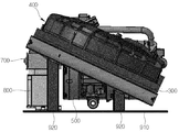
- the casing 200 has a bottom plate 910 positioned on an inner bottom surface and one end connected to the bottom plate 910, and a pedestal 920 having the other end extending to different lengths toward the condenser 300. Is provided, the condenser 300 is inclined by the pedestal 920 is disposed.
- the condenser 300 is disposed inclined to one side by the pedestal 920 as shown in the figure in a spaced state without being in close contact with the bottom plate 910.
- the pedestal 920 extends longer than the pedestal positioned at the lower center of the pedestal provided at the corner position along the edge of the bottom plate 910 with reference to FIG. 3. It is disposed to be inclined to one side.
- the condenser 300 when the condenser 300 is disposed to be inclined, a space in which the driving wind can be introduced is formed in the upper side and the lower side, and the cooling effect of the condenser 300 can be improved by using the space, which is advantageous in terms of cooling efficiency.
- the condenser 300 is positioned facing the fan unit 400 and has a corresponding size.
- the condenser 300 is formed in the form shown in the drawings.
- the condenser 300 is inclined at any one angle selected from the inclination angle is more than 15 degrees and less than 30 degrees.
- the angle is inclined at the above-described angle in consideration of the size and arrangement of the casing 200, for example, the present embodiment is disposed in the condenser 300 at the above-described angle to maintain the height of the casing 200 as low as possible. do.
- the design freedom of the peripheral layout and the peripheral components of the casing 200 can be improved, thereby enabling more stable space arrangement.
- the casing 200 has a first separation space S1 formed at a position spaced upwardly between an inner bottom surface and the condenser 300, and an inner upper surface of the casing 200 and the fan unit 400.
- the second separation space S2 is formed therebetween.
- the first separation space S1 and the second separation space S2 provide a space for stably moving the blowing air and improving the cooling efficiency of the electrical equipment 102.
- the condenser 300 may be more advantageous for the movement of the blown air when the first separation space S1 is formed, rather than being disposed in close contact with the inner bottom of the casing 100, and is sufficient for heat exchange of the condenser 300. Space can be secured.
- Fan unit 400 is a Siroco fan (Siroco fan) is used, but other types of fans may be used.
- the fan unit 400 is an axial fan (Axial fan) is used, it is installed inclined in the interior of the casing 200, it is disposed to be inclined at an acute angle smaller than a right angle.
- the fan unit 400 when the fan unit 400 is disposed to be inclined, the fan unit 400 is more advantageous to the inflow of the blowing air, and when the air is introduced through the first blowing grill 202a opened on the upper surface of the casing 200, it is partially blocked or stagnant. It is stable without any phenomenon.
- the casing 200 according to the present embodiment is formed in a rectangular parallelepiped shape, for example, the length corresponding to the height (b) is shorter than the length corresponding to the length corresponding to the width (a) or the length (C) of the plate shape While having a shape, it is made of a compact configuration.
- the height b is protruded low, thereby preventing interference with surrounding layout and surrounding components, thereby improving design freedom of the designer.
- the blower grille 202 may include a first blower grille 202a opened in an upper surface of the casing 200, a second blower grille 910b opened in the bottom plate 910, and the casing 200. And a third blower grill 202c which is open at the front side.
- the first blower grill 202a may be opened in the form shown in the figure for the inflow of blown air, but may be in another form or in another arrangement.
- the first blowing grill 202a and the second blowing grill 910b face each other and have a corresponding size, when the driving wind flows through the first blowing grill 202a, the second blowing grill 910b is opened. Can be moved stably through the movement stability is improved.
- the second blower grill 910b is formed to move the blown air, like the first blower grill 202a, and may have a different size than the first blower grill 202a.
- the second blower grill 910b may be formed larger than an opened size of the first blower grill 202a.
- the second blower grill 910b is configured to be larger than the first blower grill 202a because the second blower grill 910b needs to be supplied toward the electric equipment 102, and thus is configured as described above.
- the third blowing grill 202c is provided to move the blowing air to the front of the casing 200.
- the chiller unit 800 includes a rectangular parallelepiped having a predetermined size, and a plurality of coolant pipes 4 are provided on the upper side.
- the cooling water pipe 4 may be provided with a separate insulation (not shown) on the outside to prevent heat loss.
- the present embodiment uses the driving wind introduced into the room while the vehicle is traveling, or uses the blowing air discharged into the room when the vehicle is switched to the bet mode, for the condenser 300. Cooling can be performed.
- the casing 200 is formed in a structure that is advantageous for the inflow of the driving wind or the blowing air introduced into the room while the vehicle is traveling.
- the condenser 300 and the fan unit 400 disposed inside the casing 200 it is possible to efficiently cool the electrical equipment 102.
- the air required for cooling the electrical equipment 102 flows into the blowing air discharged into the room through the first blowing grill 202a described above, and the fan unit ( 400 is supplied to the condenser 300.
- the autonomous vehicle 10 receives a part of the air necessary for cooling the condenser 300 through an extractor grill (not shown) when the vehicle is driven in the outdoor air mode.
- the casing 200 is located at a position where an upper surface thereof is adjacent to an EXTRACTOR GRILL provided in the vehicle.
- the outside air required for cooling the condenser 300 may be supplied through the extractor grill.
- the condenser 300 may prevent overheating even when the temperature rises due to a high temperature refrigerant, thereby preventing an error or failure even when the autonomous vehicle 10 is driven for a long time.
- the autonomous vehicle 10 can efficiently cool the condenser 300 according to the internal mode and the internal mode.
- the electronic component controller 104 processes a plurality of data while the self-heating temperature rises to about 90 degrees. Speed may be reduced.
- the electronic device 102 may generate an error due to self-heating, which may lead to an accident of the autonomous vehicle 10, but the present embodiment may provide a chiller unit 800 for cooling the electronic device 102. ), Stable cooling can be performed.
- the electronic device controller 104 is provided to more efficiently perform the cooling of the electronic device 102 described above, and to control the electronic device 102 according to the room temperature and pressure of the autonomous vehicle 10, and is connected to the main controller 600. It works.
- the electronic device control unit 104 is provided to control the operating state of the electronic device 102, for example, the electronic device control unit 104 is a pressure inside the vehicle from the pressure sensor (P1) for detecting a pressure change in the vehicle interior
- the controller receives the change data, and receives the temperature change data of the inside of the vehicle from a temperature sensor T1 that detects a change in temperature of the inside of the vehicle.
- the pressure sensor P1 detects a pressure generated when the blown air moves through the fan unit 400 provided in the casing 200, and transmits the currently sensed pressure data to the electronic device controller 104.
- the temperature sensor T1 senses the temperature of the blowing air flowing into the casing 200 and transmits the currently sensed temperature data to the electrical appliance control unit 104.
- the electrical appliance control unit 104 receives the data sensed by the pressure sensor P1 and the temperature sensor T1 and transmits the data to the main control unit 600.
- the main control unit 600 receives the data transmitted from the electronic device control unit 104 and controls the blowing mode of the vehicle to switch from the bet mode to the outside air mode before the electric compressor 500 is turned off. .
- the air of the autonomous vehicle 10 is supplied with a blowing air heated at a predetermined temperature for heating.
- the autonomous vehicle 10 is driven for a long time, when the temperature due to heat generation in the electrical appliance 102 increases, it switches from the bet mode to the outside air mode.
- the electrical appliance 102 is stable cooling by mode conversion of the blowing air, and even when the autonomous vehicle 10 runs for a long time, normal driving continues without an error or malfunction.
- the motor-driven compressor 500 according to the present embodiment is turned off when the room temperature of the autonomous vehicle 10 is lower than the reference value or the reference value for efficient operation, and is turned on when it is higher than the reference value.
- the electric compressor 500 When the electric compressor 500 is turned off, the cooling air blown into the inside of the casing 200 flows into the casing 200, and the cooling is performed. When the temperature of the air blowing air is increased, the electric compressor 500 is turned on. The coolant is phase-changed at a low temperature to the chiller unit 800 while being operated, and the coolant is moved through the aforementioned coolant pipe 4 to cool the cooling object 100.
- This embodiment is to perform the cooling through the vehicle electronics cooling device for the electric equipment provided in the autonomous vehicle.
Landscapes
- Engineering & Computer Science (AREA)
- Physics & Mathematics (AREA)
- Thermal Sciences (AREA)
- Microelectronics & Electronic Packaging (AREA)
- Mechanical Engineering (AREA)
- General Engineering & Computer Science (AREA)
- Cooling Or The Like Of Electrical Apparatus (AREA)
Abstract
본 발명은 차량용 전장품 냉각 장치에 관한 것이다. 이를 위해 본 실시 예는 주행풍이 흡입되는 방향에 대해 응축기(300)과 팬 유닛(400)을 경사지게 기울어져 배치한 차량용 전장품 냉각 장치에 관한 것이다.
Description
본 실시 예는 자율 주행차량에 구비된 전장품에 대한 쿨링을 도모하기 위한 것으로, 보다 상세하게는 차량용 전장품 냉각 장치에 관한 것이다.
일반적으로 내연기관(가솔린 엔진 또는 디젤 엔진)과 전기모터의 조합으로 형성된 하이브리드시스템이라 불리우는 파워트레인(power train)을 각각 탑재한 차량들이 개발되어 실용화되어 있다.
상기 차량은 전기기기, 주행에 사용되는 전기모터를 구동하기 위해 예컨대 2차전지 또는 캐패시터와 같은 축전기구 및 인버터 또는 DC/DC 컨버터와 같은 전력변환용 기기를 탑재하고 있다.
상기 2차 전지는 발열을 포함하는 화학반응을 통해 충방전되므로, 냉각을 필요로 한다. 또한 인버터 및 DC/DC 컨버터는 열을 발생시키는 파워 소자를 구비하므로, 냉각을 필요로 한다. 일반적으로, 전기기기는 전력선을 통해 전류가 흐를 때, Joule 열이 발생되기 때문에 냉각을 필요로 한다.
상기 전기기기는 차량 뒷좌석과 트렁크 사이에 배치될 수도 있다. 상기 전기기기는 공기통로를 형성하는 덕트형 케이싱에 배치된다. 전기기기를 냉각시키기 위해 냉각풍을 발생시키는 냉각팬은 케이싱 내의 전기기기의 흡기 상류측에서 전기기기와 뒷좌석 사이에 배치된다.
상기 케이싱의 상류단부는 차량 실내와 연통되는데 일 예로 리어패키지트레이(rear package tray)에서 개방되며, 상기 전기기기가 차량 실내의 공기로 냉각된다.
상기 인버터 및 DC/DC 컨버터는 PCU(Power Control Unit)라 불리우는 전기기기 내에 통합되어, 차량 상에 탑재될 수도 있다. 상기 PCU는 또한 차량 뒷좌석과 트령크 사이에 전기기기로서 배치될 수도 있다.
하이브리드차량은 이러한 전기기기를 엔진과 함께 탑재하여야만 한다. 일본특허공개공보 제2004-161058호에는 차량의 외부에 대하여 차량 상에 탑재된 배터리에서 발생될 가능성도 있는 수소가스 등을 확실하게 방출시킬 수 있는 배터리 냉각덕트가 개시되어 있다.
상기 공보에 개시된 배터리 냉각덕트는 배터리를 탑재한 차량에 적용되고, 상기 배터리냉각덕트는 배터리를 차량의 실내와 연통시키는 연통로(communicating passage) 및 상기 연통로에 제공된 가스유지부(gas retaining unit)를 포함한다.
상기 배터리덕트는 배터리에서 발생되는 수소가스 등이 상기 가스유지부에 임시로 저장될 수 있으므로, 가스가 차량 실내로 침투하는 것을 줄이거나 막을 수 있다.
일본특허공개공보 제2005-186868호에는 차내 공간에 대한 영향들과 압력 손실을 억제할 수 있는 축전기구용 냉각장치가 개시되어 있다. 상기 공보에 개시된 축전기구용 냉각장치는 축전기구로부터 차내 공간으로의 축전기구에 의한 열교환에 의하여 가열된 공기를 배출하는 배출부 및 상기 차내 공간으로부터 차량의 외부로 열교환에 의해 가열된 공기를 배출하는 배출팬을 포함한다.
상기 축전기구용 냉각장치에 의하면, 축전기구에 의한 열교환에 의해 가열된 공기는 축전기구로부터 차내 공간으로 배출된다. 이러한 공기는 그 후에 배출팬에 의해 차내 공간으로부터 차량의 외부로 배출된다.
상기 축전기구로부터 차량의 외부로 유도하여 상기 차내 공간을 우회시키는 배기덕트를 추가로 제공하지 않고도, 열교환에 의해 가열된 공기를 차량의 외부로 배출시킬 수 있게 된다. 이에 따라, 차내 공간에 대한 영향들과 압력 손실을 억제할 수 있게 된다.
일본특허공개공보 제2004-161058호 및 일본특허공개공보 제2005-186868호에 개시된 장치들을 탑재한 차량에서는, 전기기기가 차량의 후방측에 탑재되어 차량 실내의 공기로 냉각되는 경우에, 리어패키지 트레이에 냉각풍 흡입구가 구비될 수도 있다.
그러나 흡입구가 리어패키지 트레이에 제공된다면, 상기 흡입구는 리어윈드실드에 근접하여 위치되고, 태양광의 적외선으로 조사되어, 상기 흡입구에 근접한 공기의 온도를 상승시키게 된다. 이경우 냉각풍의 온도가 상승하게 되어, 전기기기가 효율적으로 냉각될 수 없게 된다.
최근에는 자율 주행차가 개발되면서 모듈화된 구조로 이루어진 전장품 개별 쿨러가 구비되는데, 상기 전장품은 일 예로 Lidar, Radar, 각종 센서, CPU, GPU가 구비된 자립형 시스템(STAND ALONE SYSTEM)을 예로 들 수 있다.
상기 자립형 시스템은 냉각을 위해 개별 쿨러가 설치되며, 상기 전장품에 송풍을 통해 쿨링을 실시하고 있으나 별도의 에어 덕트가 필요하여 가격과 설계적으로 불리한 측면이 있었다.
또한 냉각수 라인에서 공기 제거를 위해 항시 전기 파트(ELECTRIC PART) 보다 상측에 위치해야 되므로 설계에 대한 제약이 존재하였고, 상기 개별 쿨러가 실내에 위치되면서 발생되는 소음으로 인해 노이즈가 증가되는 문제점이 유발되었다.
본 발명은 상기와 같은 문제점을 해결하기 위해 안출된 것으로, 자율 주행차량에 구비된 전장품에 대한 안정적인 냉각을 도모할 수 있는 차량용 전장품 냉각 장치를 제공한다.
상기와 같은 목적을 달성하기 위해 본 발명의 일 실시 예에 의한 차량용 냉각 장치는 냉매를 압축하여 순환시키는 전동 압축기(500); 압축된 상기 냉매를 응축하는 응축기(300); 응축된 상기 냉매를 교축하는 팽창밸브(700); 교축된 상기 냉매와 냉각수를 열교환하는 칠러 유닛(800); 및 상기 응축기(300)의 전방에 인접 배치되어, 압축된 상기 냉매를 응축시키기 위한 주행풍을 흡입하는 팬 유닛(400)을 포함하되, 상기 주행풍이 흡입되는 방향에 대해 상기 응축기(300)과 상기 팬 유닛(400)은 경사지게 기울어져 배치된다.
상기 응축기(300)는 공기의 이동이 이루어지도록 소정의 크기로 개구된 송풍 그릴(202)이 형성된 케이싱(200)의 내측에 구비된다.
상기 케이싱(200)은 직육면체 형태로 형성되되, 높이(b)에 해당되는 길이가 가로(a)에 해당되는 길이 또는 세로(c)에 해당되는 길이 보다 짧게 연장된다.
소정의 온도로 자체 발열되는 복수의 전장품(102)으로 이루어진 냉각 대상물(100)에 대한 냉각을 위해 상기 칠러 유닛(800)에서 분기되어 상기 냉각 대상물(100)을 경유한 후에 상기 칠러 유닛(800)으로 재순환되는 루프(Loop)를 형성하고, 냉각수가 이동하는 통로를 제공하는 냉각수 관(4)을 포함한다.
상기 전장품(102)은 자율 주행차량(10)에 구비된다.
상기 케이싱(200)에는 내측 바닥면에 위치된 바닥판(910); 상기 바닥판(910)에 일단이 연결되고, 타단이 상기 응축기(300)를 향해 서로 다른 길이로 연장된 받침대(920)가 구비되고, 상기 받침대(920)에 의해 상기 응축기(300)가 경사지게 배치된다.
상기 송풍 그릴(202)은 상기 케이싱(200)의 상면에 개구된 제1 송풍 그릴(202a); 상기 바닥판(910)에 개구된 제2 송풍 그릴(910b); 상기 케이싱(200)의 전면에 개구된 제3 송풍 그릴(202c)을 포함한다.
상기 제1 송풍 그릴(202a)과 상기 제2 송풍 그릴(910b)은 서로 마주보며 대응되는 크기로 형성된다.
상기 제2 송풍 그릴(910b)은 상기 제1 송풍 그릴(202a)의 개구된 크기 보다 크게 형성된다.
상기 응축기(300)는 상기 팬 유닛(400)과 마주보며 위치되고, 대응되는 크기로 이루어진다.
상기 케이싱(200)의 내측 바닥면과 상기 응축기(300) 사이에는 상측으로 이격된 위치에 형성된 제1 이격 공간(S1); 상기 케이싱(200)의 내측 상면과 상기 팬 유닛(400) 사이에 형성된 제2 이격 공간(S2)이 형성된다.
상기 케이싱(200)은 상면이 상기 차량에 구비된 익스트렉터 그릴(EXTRACTOR GRILL)과 인접한 위치에 위치된다.
상기 전장품(102)은 Lidar, Radar, 각종 센서, CPU, GPU가 구비된 자립형 시스템(STAND ALONE SYSTEM)인 것을 특징으로 한다.
상기 전장품(102)의 작동 상태를 제어하는 전장품 제어부(104)가 구비되고, 상기 전장품 제어부(104)는 상기 차량 내부의 압력 변화를 감지하는 압력 센서(P1)로부터 상기 차량 내부의 압력 변동 데이터를 입력 받고, 상기 차량 내부의 온도 변화를 감지하는 온도 센서(T1)로부터 상기 차량 내부의 온도 변동 데이터를 입력 받는다.
상기 전장품 제어부(104)는 상기 전동 압축기(500)가 오프(Off)되기 이전에 상기 차량의 송풍 모드가 내기 모드에서 외기 모드로 전환되도록 상기 차량에 구비된 메인 제어부(600)로 제어 신호를 전송한다.
본 발명의 실시 예들은 자율 주행차량에 구비된 전장품에 대한 쿨링을 칠러 유닛과 냉각 대상물 사이를 순환하는 냉각수를 이용하여 냉각을 실시할 수 있다.
본 발명의 실시 예들은 송풍 공기의 온도와 압력을 감지하여 전동 압축기와 연계되어 열교환 유닛에 대한 냉각과, 냉각 대상물에 대한 냉각을 칠러 유닛을 통해 실시할 수 있어 냉각 효율이 향상된다.
도 1은 본 발명의 일 실시 예에 의한 차량용 전장품 냉각 장치의 전체 구성을 간략히 도시한 도면.
도 2는 본 발명의 일 실시 예에 의한 차량용 전장품 냉각 장치의 사시도.
도 3 내지 도 5는 본 발명의 일 실시 예에 의한 차량용 전장품 냉각 장치의 내부 구성을 다양한 각도에서 도시한 사시도.
도 6은 본 발명의 일 실시 예에 의한 자율 주행차량에 탑재된 차량용 전장품 냉각 장치를 도시한 도면으로 내기 모드로 송풍이 이루어지는 상태를 도시한 도면.
도 7은 본 발명의 일 실시 예에 의한 자율 주행차량에 탑재된 차량용 전장품 냉각 장치를 도시한 도면으로 외기 모드로 송풍이 이루어지는 상태를 도시한 도면.
도 8은 본 발명의 일 실시 에에 의한 케이싱의 내부를 경유한 송풍 공기가 냉각 대상물로 이동하는 상태를 도시한 도면.
도 9는 본 발명의 일 실시 예에 의한 전장품 제어부와 메인 제어부 및 이와 연계된 주변 구성을 도시한 도면.
본 발명의 일 실시 예에 의한 차량용 냉각 장치 차량에 대해 도면을 참조하여 설명한다. 첨부된 도 1은 본 발명의 일 실시 예에 의한 차량용 전장품 냉각 장치의 전체 구성을 간략히 도시한 도면이고, 도 2는 본 발명의 일 실시 예에 의한 차량용 전장품 냉각 장치의 사시도이며, 도 3 내지 도 5는 본 발명의 일 실시 예에 의한 차량용 전장품 냉각 장치의 내부 구성을 다양한 각도에서 도시한 사시도이다.
첨부된 도 1 내지 도 5를 참조하면, 본 실시 예는 자율 주행차량(10)(self-driving car)에 설치된 냉각 대상물(100)의 전장품(102)에 대한 냉각을 차량 실내의 송풍 모드를 이용하여 실시하기 위한 발명이다.
특히 자율 주행차량(10)(도 6 참조)은 운전자가 브레이크, 핸들, 가속페달 등을 제어하지 않아도 주행시 외부정보 감지 및 처리기능을 가지고 주변 환경을 인식하여 주행경로를 자체적으로 결정하고, 자체 동력을 이용하여 독립적으로 주행하는 시스템이다.예를 들면 운전자 없이 주행하는 차인 무인 자동차(driverless car)와는 다른 개념으로서, 운전자가 차량 내에 존재하지만 주행에는 관여하지 않는 것을 의미한다.
본 실시 예는 전동 압축기(500)에서 압축된 고온 고압의 냉매가 후술할 응축기(300)로 이동되고, 상기 냉매는 상기 응축기(300)에서 후술할 팬 유닛(400)에 의해 공랭식으로 냉각된다.
상기 냉매는 냉매관(2)을 따라 팽창밸브(700)(도 5 참조)를 경유하면서 저온 저압 상태로 후술할 칠러 유닛(800)으로 공급된다. 상기 칠러 유닛(800)은 일종의 증발기로서 상기 팽창밸브(700)를 경유하기 이전의 고온 고압의 액체 냉매를 저온 저압의 기체 냉매로 상변화 시켜 상기 전동 압축기(500)로 공급한다.
이와 같이 냉매는 전술한 구성품들을 반복적으로 경유하면서 상변화하고, 차량의 냉방을 도모한다.
이와 함께 자율 주행 차량은 운전자의 운전 편의성을 위해 전장품(102)이 구비되고, 상기 전장품(102)은 일 예로 Lidar, Radar, 각종 센서, CPU, GPU가 구비된 자립형 시스템(STAND ALONE SYSTEM)이 사용된다.
상기 Lidar는 light detection and ranging의 약자로 레이저레이더(laser radar)와 같다. 전파에 가까운 성질을 가진 레이저광선을 사용하여 개발한 레이더라고 볼 수 있다.
상기 Lidar는 펄스 레이저광을 대기중으로 발사하고, 발사된 반사체 또는 산란체를 이용하여 거리 또는 대기현상 등을 측정할 수 있다.
특히 자율 주행차량(10)은 주변 상황을 정확하게 파악하기 위해 각종 센서와 카메라가 구비되는데, 상기 라이다 주변 환경을 2차원으로 인식하여 상기 자율 주행차량(10)이 안전하게 주행할 수 있도록 한다.
상기 Radar는 무선탐지와 거리측정(Radio Detecting And Ranging)의 약어로 마이크로파(극초단파, 10cm ~ 100cm 파장) 정도의 전자기파를 전방 또는 측후방 차량을 향해 발사시키고, 상기 차량에서 반사되는 전자기파를 수신하여 상기 차량과의 거리와, 방향 및 고도 등을 감지할 수 있는 무선감시장치이다.
상기 Lidar는 현재 자율 주행차량(10) 주위에서 차량 주행에 필요한 데이터를 획득하고, 상기 Radar 또한 획득된 데이터를 후술할 전장품 제어부(104)(도 9 참조)로 전송한다.
상기 냉각 대상물(100)은 내부에 구비된 전장품(102)이 자율 주행차량(10)의 안정적인 주행을 위해 다수개의 구성품으로 구성되고, 차실 내부에 설치될 경우 작동에 따른 발열로 인한 문제점이 최소화 되도록 칠러 유닛(800)과 연결된 냉각수 관(4)을 통해 냉각수를 순환시켜 냉각 대상물(100)에 대한 냉각을 실시한다.
이를 위해 본 실시 예는 냉매를 압축하여 순환시키는 전동 압축기(500)와, 압축된 상기 냉매를 응축하는 응축기(300)와, 응축된 상기 냉매를 교축하는 팽창밸브(700)와, 교축된 상기 냉매와 냉각수를 열교환하는 칠러 유닛(800) 및 상기 응축기(300)의 전방에 인접 배치되어, 압축된 상기 냉매를 응축시키기 위한 주행풍을 흡입하는 팬 유닛(400)을 포함한다. 그리고 상기 주행풍이 흡입되는 방향에 대해 상기 응축기(300)과 상기 팬 유닛(400)은 경사지게 기울어져 배치된다.
특히 케이싱(200)의 내부에는 응축기(300)과, 팬 유닛(400)과, 전동 압축기(500)와, 칠러 유닛(800)이 패키지화되어 구성되고, 상측에 전술한 냉각 대상물(100)이 구비된다. 상기 응축기(300)는 공기의 이동이 이루어지도록 소정의 크기로 개구된 송풍 그릴(202)이 형성된 케이싱(200)의 내측에 구비되므로 작동시 고온으로 발열되는 경우에도 안정적인 냉각이 이루어진다.
본 실시 예에 의한 응축기(300)는 팬 유닛(400)을 통해 냉각을 실시하고, 상기 냉각 대상물(100)은 칠러 유닛(800)을 통해 냉각을 실시하여 자율 주행차량(10)의 안정적인 주행과 냉각을 도모할 수 있다.
본 실시 예는 칠러 유닛(800)과 냉각 대상물(100) 사이에 냉각수 관(4)이 연결되어 있어 서로 간에 유체 이동 가능해진다. 일 예로 상기 칠러 유닛(4)에서 상기 냉각 대상물(100)로 저온의 냉각수가 공급되면 상기 냉각 대상물(100)에서 냉각이 이루어진다.
그리고 상기 냉각수는 상기 냉각 대상물(100)에서 소정의 시간 동안 열교환을 통해 온도가 상승한 후에, 화살표로 도시된 바와 같이 상기 칠러 유닛(800)으로 공급되어 저온의 냉매와 열교환이 이루어진 후에 다시 상기 칠러 유닛(800)에서 상기 냉각 대상물(100)로 공급된다.
이와 같이 저온의 냉각수가 상기 냉각수 관(4)을 통해 지속적으로 상기 냉각 대상물(100) 사이를 순환 이동할 경우 상기 냉각 대상물(100)의 발열에 따른 과열을 방지할 수 있다. 특히 여름과 같이 차 실내 또는 외기의 온도가 고온으로 유지되는 경우에 전동 압축기(500)의 작동과 동시에 냉각을 실시하여 안정적인 작동을 유지할 수 있다.
상기 케이싱(200)에는 내측 바닥면에 위치된 바닥판(910)과, 상기 바닥판(910)에 일단이 연결되고, 타단이 상기 응축기(300)을 향해 서로 다른 길이로 연장된 받침대(920)가 구비되고, 상기 받침대(920)에 의해 상기 응축기(300)가 경사지게 배치된다.
상기 응축기(300)는 상기 바닥판(910)에 밀착되지 않고 이격된 상태로 도면에 도시된 바와 같이 받침대(920)에 의해 일측 으로 경사지게 배치된다. 상기 받침대(920)는 도 3을 기준으로 상기 바닥판(910)의 가장 자리를 따라 모서리 위치에 구비된 받침대의 길이가 중앙 하측에 위치된 받침대 보다 길게 연장되므로 상기 응축기(300)가 설치될 경우 일측으로 경사지게 배치된다.
이와 같이 상기 응축기(300)가 경사지게 배치될 경우 상측과 하측에 주행풍이 유입 가능한 공간이 형성되고, 상기 공간을 이용하여 응축기(300)의 냉각 효과를 향상시킬 수 있어 냉각 효율 측면에서 유리해 진다.
상기 응축기(300)는 상기 팬 유닛(400)과 마주보며 위치되고, 대응되는 크기로 이루어진다. 상기 응축기(300)는 도면에 도시된 형태로 이루어진다.상기 응축기(300)는 경사진 각도가 15도 이상 30도 이내 중에서 선택되는 어느 하나의 각도로 경사지게 배치된다. 상기 각도는 케이싱(200)의 크기 및 배치 관계를 고려하여 전술한 각도로 경사지며, 일 예로 본 실시 예는 케이싱(200)의 높이를 최대한 낮게 유지하기 위해 전술한 각도로 응축기(300)가 배치된다.
이 경우 상기 케이싱(200)의 주변 레이 아웃과 주변 구성품에 대한 설계 자유도가 향상될 수 있어 보다 안정적인 공간 배치가 가능해진다.
상기 케이싱(200)은 내측 바닥면과 상기 응축기(300) 사이에 상측으로 이격된 위치에 형성된 제1 이격 공간(S1)이 형성되고, 상기 케이싱(200)의 내측 상면과 상기 팬 유닛(400) 사이에 제2 이격 공간(S2)이 형성된다.
상기 제1 이격 공간(S1)과 제2 이격 공간(S2)은 송풍 공기의 안정적인 이동을 도모하고, 상기 전장품(102)의 쿨링 효율을 향상시키기 위한 공간을 제공한다.
상기 응축기(300)는 케이싱(100)의 내측 바닥에 밀착되게 배치되는 것 보다는 제1 이격 공간(S1)이 형성될 경우 송풍 공기의 이동에 보다 유리할 수 있으며 상기 응축기(300)의 열교환을 위한 충분한 공간이 확보될 수 있다.
팬 유닛(400)은 시로코 팬(Siroco fan)이 사용되나 다른 형태의 팬이 사용되는 것도 가능하다. 상기 팬 유닛(400)은 엑시얼 팬(Axial fan)이 사용되며, 상기 케이싱(200)의 내부에 경사지게 설치되되, 직각 보다 작은 예각으로 기울어지게 배치된다.
이와 같이 팬 유닛(400)이 경사지게 배치될 경우 송풍 공기의 유입에 보다 유리해지며, 케이싱(200)의 상면에 개구된 제1 송풍 그릴(202a)을 통해 공기 유입이 이루어질 때 부분적으로 막히거나 정체되는 현상 없이 안정적으로 이루어진다.
본 실시 예에 의한 케이싱(200)은 직육면체 형태로 형성되되, 일 예로 높이(b)에 해당되는 길이가 가로(a)에 해당되는 길이 또는 세로(C)에 해당되는 길이 보다 짧게 연장되므로 판형의 형태를 갖으면서, 컴팩트한 구성으로 이루어진다.
이와 같이 케이싱(200)이 형성될 경우 높이(b)가 낮게 돌출되므로 주변 레이아웃 및 주변 구성품들과 간섭되는 현상이 방지되므로 설계자의 설계 자유도가 향상된다.
상기 송풍 그릴(202)은 상기 케이싱(200)의 상면에 개구된 제1 송풍 그릴(202a)과, 상기 바닥판(910)에 개구된 제2 송풍 그릴(910b)과, 상기 케이싱(200)의 전면에 개구된 제3 송풍 그릴(202c)을 포함한다.
상기 제1 송풍 그릴(202a)은 송풍 공기의 유입을 위해 도면에 도시된 형태로 개구되나 다른 형태 또는 다른 배열로 이루어질 수 있다.
상기 제1 송풍 그릴(202a)과 상기 제2 송풍 그릴(910b)은 서로 마주보며 대응되는 크기로 형성되므로 상기 제1 송풍 그릴(202a)을 통해 주행풍이 유입될 경우 제2 송풍 그릴(910b)을 통해 안정적으로 이동될 수 있어 이동 안정성이 향상된다.
제2 송풍 그릴(910b)은 제1 송풍 그릴(202a)과 같이 송풍 공기의 이동을 위해 형성되는데, 상기 제1 송풍 그릴(202a)과 상이한 크기로 형성될 수 있다. 일 예로 상기 제2 송풍 그릴(910b)이 상기 제1 송풍 그릴(202a)의 개구된 크기 보다 크게 형성될 수 있다.
상기 제2 송풍 그릴(910b)은 송풍 공기를 전장품(102)을 향해 공급해야 하므로 상기 제1 송풍 그릴(202a) 보다 크게 개구되는 것이 유리하므로 위와 같이 구성된다.
제3 송풍 그릴(202c)은 케이싱(200)의 전면으로 송풍 공기의 이동을 위해 구비된다. 첨부된 도 5를 참조하면, 칠러 유닛(800)은 소정의 크기로 이루어진 직육면체로 구성되고, 상측에 냉각수 관(4)이 복수개로 구비된다. 상기 냉각수 관(4)은 열손실이 방지되도록 외측에 별도의 보온재(미도시)가 구비될 수 있다.
첨부된 도 6 내지 도 8을 참조하면, 본 실시 예는 차량이 주행하면서 실내로 유입되는 주행풍을 이용하거나, 내기 모드로 전환될 때 실내로 토출되는 송풍 공기를 이용하여 응축기(300)에 대한 냉각을 실시할 수 있다.
또한 본 실시 예는 차량이 주행하면서 실내로 유입되는 주행풍 또는 송풍 공기의 유입에 유리한 구조로 케이싱(200)이 형성된다. 그리고 상기 케이싱(200)의 내부에 배치된 응축기(300) 및 팬 유닛(400)의 배치를 통해 전장품(102)의 효율적인 냉각을 도모할 수 있다.
예를 들면 자율 주행차량(10)이 내기 모드로 주행될 경우 전장품(102)의 쿨링에 필요한 공기는 실내로 토출된 송풍 공기가 전술한 제1 송풍 그릴(202a)를 통해 유입되고, 팬 유닛(400)을 통해 응축기(300)로 공급된다.
자율 주행차량(10)은 외기모드로 주행이 이루어질 경우 응축기(300)의 쿨링에 필요한 공기를 익스크렉터 그릴(미도시)을 통해 일부 공급받는다. 일 예로 상기 케이싱(200)은 상면이 상기 차량에 구비된 익스트렉터 그릴(EXTRACTOR GRILL)과 인접한 위치에 위치된다. 이 경우 응축기(300)의 쿨링에 필요한 외기를 상기 익스트렉터 그릴을 통해 공급 받을 수 있다.
이 경우 외기가 실내 온도 보다 저온일 경우 응축기(300)의 냉각에 필요한 송풍 공기를 실내로 토출된 송풍 공기에만 의존하지 않고 외기의 일부를 케이싱(200)의 내부로 유입하여 쿨링에 필요한 공기로 이용할 수 있다.
따라서 상기 응축기(300)는 고온의 냉매로 의한 온도 상승이 이루어지는 경우에도 과열이 방지될 수 있어 장시간 자율 주행차량(10)의 주행이 이루어지는 경우에도 에러 또는 고장 발생을 예방할 수 있다.
자율 주행차량(10)이 외기 모드일 경우 전술한 실시 예와 함께 차 실내로 유입된 송풍 공기 중의 일부는 케이싱(200)에 형성된 송풍 그릴(202)을 경유 하면서 냉각된 공기에 의해 쿨링이 이루어진다.
따라서 자율 주행차량(10)은 내기 모드와 외기 모드에 따라 응축기(300)에 대한 냉각을 효율적으로 실시할 수 있다.
첨부된 도 9를 참조하면, 전장품 제어부(104)는 상기 Lidar와 Radar와 각종 센서와 CPU 및 GPU가 동시에 작동될 경우 90도 전후의 온도로 자체 발열 온도가 상승하면서 다수의 데이터를 처리하기 위한 처리 속도가 저하될 수 있다.
이 경우 전장품(102)은 자체 발열로 인해 에러가 발생될 수 있으며 이는 상기 자율 주행차량(10)의 사고로 이어질 수 있으나, 본 실시 예는 상기 전장품(102)에 대한 쿨링을 위해 칠러 유닛(800)이 구비되어 있으므로 안정적인 쿨링을 실시할 수 있다.
상기 전장품 제어부(104)는 전술한 전장품(102)에 대한 쿨링을 보다 효율적으로 실시하고, 자율 주행차량(10)의 실내 온도 및 압력에 따라 제어하기 위해 구비되고, 메인 제어부(600)와 연계되어 작동된다.
상기 전장품 제어부(104)는 전장품(102)의 작동 상태를 제어하기 위해 구비되는데, 일 예로 상기 전장품 제어부(104)는 상기 차량 내부의 압력 변화를 감지하는 압력 센서(P1)로부터 상기 차량 내부의 압력 변동 데이터를 입력 받고, 상기 차량 내부의 온도 변화를 감지하는 온도 센서(T1)로부터 상기 차량 내부의 온도 변동 데이터를 입력 받는다.
압력 센서(P1)는 송풍 공기가 케이싱(200)에 구비된 팬 유닛(400)을 통해 이동할 때 발생되는 압력을 감지하여 상기 전장품 제어부(104)로 현재 감지된 압력 데이터를 전송한다.
상기 온도 센서(T1)은 상기 케이싱(200)으로 유입되는 송풍 공기의 온도를 감지하여 전장품 제어부(104)로 현재 감지된 온도 데이터를 전송한다.
상기 전장품 제어부(104)는 압력 센서(P1)와 온도 센서(T1)에서 감지된 데이터를 입력 받아 상기 메인 제어부(600)로 해당 데이터를 전송한다.
상기 메인 제어부(600)는 상기 전장품 제어부(104)에서 전송한 데이터를 입력 받아 상기 전동 압축기(500)가 오프(Off)되기 이전에 상기 차량의 송풍 모드가 내기 모드에서 외기 모드로 전환되도록 제어한다.
예를 들어 겨울철의 경우 자율 주행차량(10)의 실내는 난방을 위해 소정의 온도로 가열된 송풍 공기가 내기 모드로 공급된다. 자율 주행차량(10)이 장시간 주행되면서 전장품(102)에서 발열로 인한 온도가 증가될 경우 내기 모드에서 외기 모드로 전환된다.
상기 외기 모드는 실내 공기 온도 보다 상대적으로 차가운 외기가 실내로 유입되므로 송풍 그릴(202)을 통해 응축기(300)로 저온의 송풍 공기가 공급되면서 쿨링이 이루어진다.
따라서 상기 전장품(102)은 송풍 공기의 모드 변환으로 안정적인 냉각이 이루어지고, 자율 주행차량(10)도 장시간 주행이 이루어지는 경우에도 에러 또는 오작동되지 않고 정상적인 주행이 지속된다.
본 실시 예에 의한 전동 압축기(500)는 효율적인 작동을 위해 자율 주행차량(10)의 실내 온도가 기준치 또는 기준치 보다 낮을 경우 오프(Off) 되고, 기준치 보다 높을 경우 온(On) 작동된다.
전동 압축기(500)가 오프 되면 실내로 송풍된 송풍 공기가 상기 케이싱(200)의 내측으로 유입되면서 쿨링이 이루어지다가, 상기 송풍 공기의 온도가 상승될 경우 상기 전동 압축기(500)는 온(On) 작동되면서 칠러 유닛(800)으로 저온으로 상 변화된 냉매가 공급되고, 전술한 냉각수 관(4)을 통해 냉각수가 이동되어 냉각 대상물(100)에 대한 쿨링이 이루어진다.
본 실시 예는 자율 주행차량에 구비된 전장품에 대한 차량용 전장품 냉각 장치를 통해 냉각을 실시하고자 한다.
Claims (15)
- 냉매를 압축하여 순환시키는 전동 압축기(500);압축된 상기 냉매를 응축하는 응축기(300);응축된 상기 냉매를 교축하는 팽창밸브(700);교축된 상기 냉매와 냉각수를 열교환하는 칠러 유닛(800); 및상기 응축기(300)의 전방에 인접 배치되어, 압축된 상기 냉매를 응축시키기 위한 주행풍을 흡입하는 팬 유닛(400)을 포함하되,상기 주행풍이 흡입되는 방향에 대해 상기 응축기(300)과 상기 팬 유닛(400)은 경사지게 기울어져 배치되는 차량용 전장품 냉각 장치.
- 제1 항에 있어서,상기 응축기(300)는 공기의 이동이 이루어지도록 소정의 크기로 개구된 송풍 그릴(202)이 형성된 케이싱(200)의 내측에 구비된 차량용 전장품 냉각 장치.
- 제1 항에 있어서,상기 케이싱(200)은 직육면체 형태로 형성되되, 높이(b)에 해당되는 길이가 가로(a)에 해당되는 길이 또는 세로(c)에 해당되는 길이 보다 짧게 연장된 차량용 전장품 냉각 장치.
- 제1 항에 있어서,소정의 온도로 자체 발열되는 복수의 전장품(102)으로 이루어진 냉각 대상물(100)에 대한 냉각을 위해 상기 칠러 유닛(800)에서 분기되어 상기 냉각 대상물(100)을 경유한 후에 상기 칠러 유닛(800)으로 재순환되는 루프(Loop)를 형성하고, 냉각수가 이동하는 통로를 제공하는 냉각수 관(4)을 포함하는 차량용 전장품 냉각 장치.
- 제4 항에 있어서,상기 전장품(102)은 자율 주행차량(10)에 구비된 것을 특징으로 하는 차량용 전장품 냉각 장치.
- 제1 항에 있어서,상기 케이싱(200)에는 내측 바닥면에 위치된 바닥판(910);상기 바닥판(910)에 일단이 연결되고, 타단이 상기 응축기(300)를 향해 서로 다른 길이로 연장된 받침대(920)가 구비되고,상기 받침대(920)에 의해 상기 응축기(300)가 경사지게 배치된 차량용 전장품 냉각 장치.
- 제2 항에 있어서,상기 송풍 그릴(202)은 상기 케이싱(200)의 상면에 개구된 제1 송풍 그릴(202a);상기 바닥판(910)에 개구된 제2 송풍 그릴(910b);상기 케이싱(200)의 전면에 개구된 제3 송풍 그릴(202c)을 포함하는 차량용 전장품 냉각 장치.
- 제7 항에 있어서,상기 제1 송풍 그릴(202a)과 상기 제2 송풍 그릴(910b)은 서로 마주보며 대응되는 크기로 형성된 차량용 전장품 냉각 장치.
- 제7 항에 있어서,상기 제2 송풍 그릴(910b)은 상기 제1 송풍 그릴(202a)의 개구된 크기 보다 크게 형성된 차량용 전장품 냉각 장치.
- 제1 항에 있어서,상기 응축기(300)는 상기 팬 유닛(400)과 마주보며 위치되고, 대응되는 크기로 이루어진 차량용 전장품 냉각 장치.
- 제1 항에 있어서,상기 케이싱(200)의 내측 바닥면과 상기 응축기(300) 사이에는 상측으로 이격된 위치에 형성된 제1 이격 공간(S1);상기 케이싱(200)의 내측 상면과 상기 팬 유닛(400) 사이에 형성된 제2 이격 공간(S2)이 형성된 차량용 전장품 냉각 장치.
- 제1 항에 있어서,상기 케이싱(200)은 상면이 상기 차량에 구비된 익스트렉터 그릴(EXTRACTOR GRILL)과 인접한 위치에 위치된 차량용 전장품 냉각 장치.
- 제4 항에 있어서,상기 전장품(102)은 Lidar, Radar, 각종 센서, CPU, GPU가 구비된 자립형 시스템(STAND ALONE SYSTEM)인 것을 특징으로 하는 차량용 전장품 냉각 장치.
- 제4 항에 있어서,상기 전장품(102)의 작동 상태를 제어하는 전장품 제어부(104)가 구비되고, 상기 전장품 제어부(104)는 상기 차량 내부의 압력 변화를 감지하는 압력 센서(P1)로부터 상기 차량 내부의 압력 변동 데이터를 입력받고, 상기 차량 내부의 온도 변화를 감지하는 온도 센서(T1)로부터 상기 차량 내부의 온도 변동 데이터를 입력받는 차량용 전장품 냉각 장치.
- 제14 항에 있어서,상기 전장품 제어부(104)는 상기 전동 압축기(500)가 오프(Off)되기 이전에 상기 차량의 송풍 모드가 내기 모드에서 외기 모드로 전환되도록 상기 차량에 구비된 메인 제어부(600)로 제어 신호를 전송하는 차량용 전장품 냉각 장치.
Priority Applications (1)
| Application Number | Priority Date | Filing Date | Title |
|---|---|---|---|
| US17/053,137 US20210123636A1 (en) | 2018-06-20 | 2019-05-03 | Electrical equipment cooling system for vehicle |
Applications Claiming Priority (2)
| Application Number | Priority Date | Filing Date | Title |
|---|---|---|---|
| KR10-2018-0071019 | 2018-06-20 | ||
| KR1020180071019A KR102563739B1 (ko) | 2018-06-20 | 2018-06-20 | 차량용 전장품 냉각 장치 |
Publications (1)
| Publication Number | Publication Date |
|---|---|
| WO2019245161A1 true WO2019245161A1 (ko) | 2019-12-26 |
Family
ID=68983024
Family Applications (1)
| Application Number | Title | Priority Date | Filing Date |
|---|---|---|---|
| PCT/KR2019/005372 Ceased WO2019245161A1 (ko) | 2018-06-20 | 2019-05-03 | 차량용 전장품 냉각 장치 |
Country Status (3)
| Country | Link |
|---|---|
| US (1) | US20210123636A1 (ko) |
| KR (1) | KR102563739B1 (ko) |
| WO (1) | WO2019245161A1 (ko) |
Families Citing this family (1)
| Publication number | Priority date | Publication date | Assignee | Title |
|---|---|---|---|---|
| KR20250059110A (ko) | 2023-10-24 | 2025-05-02 | 현대모비스 주식회사 | 전자 장치 |
Citations (5)
| Publication number | Priority date | Publication date | Assignee | Title |
|---|---|---|---|---|
| KR100780488B1 (ko) * | 2002-02-28 | 2007-11-28 | 가부시키가이샤 덴소 | 차량용 공조시스템 |
| KR20080078543A (ko) * | 2007-02-23 | 2008-08-27 | 한라공조주식회사 | 차량용 배터리 냉각장치 및 그 제어방법 |
| KR20130028223A (ko) * | 2011-09-09 | 2013-03-19 | 현대자동차주식회사 | 연료전지차량용 냉각장치 |
| KR101817729B1 (ko) * | 2016-05-12 | 2018-01-11 | 갑을오토텍 주식회사 | 열전소자 열교환기와 냉매를 이용한 차량용 냉난방 시스템 |
| JP2018008541A (ja) * | 2016-07-11 | 2018-01-18 | 株式会社デンソー | 車両用空調装置 |
Family Cites Families (13)
| Publication number | Priority date | Publication date | Assignee | Title |
|---|---|---|---|---|
| KR0144562B1 (ko) * | 1989-09-12 | 1998-08-17 | 크리스트, 퀼 | 진공개폐기용 CuCr-재료의 제조방법 및 그 접점재료 |
| US5273486A (en) * | 1992-11-27 | 1993-12-28 | United Technologies Corporation | Adaptive aircraft cabin pressure control system |
| JP2004161058A (ja) | 2002-11-11 | 2004-06-10 | Toyota Motor Corp | 電池冷却ダクト |
| KR100999134B1 (ko) * | 2006-10-25 | 2010-12-08 | 현대자동차주식회사 | 자동차 공기 조화기용 내외기 제어 방법 |
| EP2658769B1 (en) * | 2010-12-27 | 2016-03-23 | Volvo Lastvagnar AB | Truck and method for controlling such a truck |
| US20120168125A1 (en) * | 2011-01-05 | 2012-07-05 | Tesla Motors, Inc. | Multi-Function Automotive Radiator and Condenser Airflow System |
| US9447997B2 (en) * | 2013-06-11 | 2016-09-20 | Pompanette, Llc | Circular evaporating coil with backward inclined blower wheel with a vertical axis rotatable discharge shroud |
| KR20140145504A (ko) * | 2013-06-13 | 2014-12-23 | 삼성전자주식회사 | 열교환기 및 이를 포함하는 공기조화기용 실외기 |
| US20150089968A1 (en) * | 2013-10-01 | 2015-04-02 | B/E Aerospace, Inc. | Aircraft air chiller with reduced profile |
| KR101703604B1 (ko) * | 2015-10-19 | 2017-02-07 | 현대자동차 주식회사 | 차량용 배터리 냉각 시스템 |
| KR102523026B1 (ko) * | 2016-02-05 | 2023-04-19 | 한온시스템 주식회사 | 차량용 배터리의 열관리 시스템 |
| JP6186578B1 (ja) * | 2016-06-20 | 2017-08-30 | 三菱重工サーマルシステムズ株式会社 | 輸送用冷凍ユニット |
| WO2019094843A1 (en) * | 2017-11-10 | 2019-05-16 | Nvidia Corporation | Systems and methods for safe and reliable autonomous vehicles |
-
2018
- 2018-06-20 KR KR1020180071019A patent/KR102563739B1/ko active Active
-
2019
- 2019-05-03 WO PCT/KR2019/005372 patent/WO2019245161A1/ko not_active Ceased
- 2019-05-03 US US17/053,137 patent/US20210123636A1/en not_active Abandoned
Patent Citations (5)
| Publication number | Priority date | Publication date | Assignee | Title |
|---|---|---|---|---|
| KR100780488B1 (ko) * | 2002-02-28 | 2007-11-28 | 가부시키가이샤 덴소 | 차량용 공조시스템 |
| KR20080078543A (ko) * | 2007-02-23 | 2008-08-27 | 한라공조주식회사 | 차량용 배터리 냉각장치 및 그 제어방법 |
| KR20130028223A (ko) * | 2011-09-09 | 2013-03-19 | 현대자동차주식회사 | 연료전지차량용 냉각장치 |
| KR101817729B1 (ko) * | 2016-05-12 | 2018-01-11 | 갑을오토텍 주식회사 | 열전소자 열교환기와 냉매를 이용한 차량용 냉난방 시스템 |
| JP2018008541A (ja) * | 2016-07-11 | 2018-01-18 | 株式会社デンソー | 車両用空調装置 |
Also Published As
| Publication number | Publication date |
|---|---|
| KR20190143275A (ko) | 2019-12-30 |
| KR102563739B1 (ko) | 2023-08-17 |
| US20210123636A1 (en) | 2021-04-29 |
Similar Documents
| Publication | Publication Date | Title |
|---|---|---|
| WO2018105927A1 (ko) | 차량용 열관리 시스템 | |
| US8360014B2 (en) | Engine housing enclosure | |
| EP4075458A1 (en) | Air-cooled wireless power transmission system | |
| WO2018105925A1 (ko) | 차량용 열관리 시스템 | |
| KR100896777B1 (ko) | 향상된 장착성을 갖는 다중 전력공급장치 | |
| KR100194646B1 (ko) | 강제 공냉 기기를 수용한 기계실에 있어서의 공기조화방법 | |
| CN101622143B (zh) | 电气设备的冷却装置及冷却方法 | |
| WO2021215695A1 (ko) | 자동차용 히트 펌프 시스템 | |
| JP5776735B2 (ja) | 電池温調装置 | |
| WO2013089503A1 (ko) | 전기 자동차의 배터리 냉각 시스템 | |
| JP5928152B2 (ja) | 自動車のバッテリの温調装置 | |
| WO2022177303A1 (ko) | 차량의 공조용 냉각수 매니폴드 및 통합 냉각수 분배 및 저장 모듈 | |
| WO2015126019A1 (ko) | 냉동차량의 냉동시스템 | |
| WO2019103377A1 (ko) | 차량용 공조장치 | |
| WO2019245161A1 (ko) | 차량용 전장품 냉각 장치 | |
| JP2012156157A (ja) | 冷却装置 | |
| ES2229570T3 (es) | Sistema de refrigeracion para enfrias armarios electricos o componente en vehiculos sobre carril. | |
| JP4075285B2 (ja) | 車両走行モ−タ駆動用インバータ回路装置 | |
| WO2018155823A1 (ko) | 차량 시트 공조장치 | |
| KR20110092921A (ko) | 차량용 배터리 냉각장치 | |
| JP2001229948A (ja) | 燃料電池車両冷却システム | |
| CN209454687U (zh) | 自动驾驶汽车的工控机箱 | |
| CN109659991B (zh) | 一种基于相变热交换的组合式直流充电系统 | |
| CN221698563U (zh) | 一种车载冰箱和车辆 | |
| CN213368423U (zh) | 一种高安全性直流电源 |
Legal Events
| Date | Code | Title | Description |
|---|---|---|---|
| 121 | Ep: the epo has been informed by wipo that ep was designated in this application |
Ref document number: 19823663 Country of ref document: EP Kind code of ref document: A1 |
|
| NENP | Non-entry into the national phase |
Ref country code: DE |
|
| 122 | Ep: pct application non-entry in european phase |
Ref document number: 19823663 Country of ref document: EP Kind code of ref document: A1 |