WO2019240271A1 - 荷役装置、その制御装置、制御方法、およびコンピュータ可読記憶媒体 - Google Patents
荷役装置、その制御装置、制御方法、およびコンピュータ可読記憶媒体 Download PDFInfo
- Publication number
- WO2019240271A1 WO2019240271A1 PCT/JP2019/023713 JP2019023713W WO2019240271A1 WO 2019240271 A1 WO2019240271 A1 WO 2019240271A1 JP 2019023713 W JP2019023713 W JP 2019023713W WO 2019240271 A1 WO2019240271 A1 WO 2019240271A1
- Authority
- WO
- WIPO (PCT)
- Prior art keywords
- area
- picking
- unit
- sensor
- blocking
- Prior art date
- Legal status (The legal status is an assumption and is not a legal conclusion. Google has not performed a legal analysis and makes no representation as to the accuracy of the status listed.)
- Ceased
Links
Images




Classifications
-
- B—PERFORMING OPERATIONS; TRANSPORTING
- B65—CONVEYING; PACKING; STORING; HANDLING THIN OR FILAMENTARY MATERIAL
- B65G—TRANSPORT OR STORAGE DEVICES, e.g. CONVEYORS FOR LOADING OR TIPPING, SHOP CONVEYOR SYSTEMS OR PNEUMATIC TUBE CONVEYORS
- B65G61/00—Use of pick-up or transfer devices or of manipulators for stacking or de-stacking articles not otherwise provided for
-
- B—PERFORMING OPERATIONS; TRANSPORTING
- B65—CONVEYING; PACKING; STORING; HANDLING THIN OR FILAMENTARY MATERIAL
- B65G—TRANSPORT OR STORAGE DEVICES, e.g. CONVEYORS FOR LOADING OR TIPPING, SHOP CONVEYOR SYSTEMS OR PNEUMATIC TUBE CONVEYORS
- B65G1/00—Storing articles, individually or in orderly arrangement, in warehouses or magazines
-
- B—PERFORMING OPERATIONS; TRANSPORTING
- B65—CONVEYING; PACKING; STORING; HANDLING THIN OR FILAMENTARY MATERIAL
- B65G—TRANSPORT OR STORAGE DEVICES, e.g. CONVEYORS FOR LOADING OR TIPPING, SHOP CONVEYOR SYSTEMS OR PNEUMATIC TUBE CONVEYORS
- B65G1/00—Storing articles, individually or in orderly arrangement, in warehouses or magazines
- B65G1/02—Storage devices
- B65G1/04—Storage devices mechanical
- B65G1/137—Storage devices mechanical with arrangements or automatic control means for selecting which articles are to be removed
-
- B—PERFORMING OPERATIONS; TRANSPORTING
- B65—CONVEYING; PACKING; STORING; HANDLING THIN OR FILAMENTARY MATERIAL
- B65G—TRANSPORT OR STORAGE DEVICES, e.g. CONVEYORS FOR LOADING OR TIPPING, SHOP CONVEYOR SYSTEMS OR PNEUMATIC TUBE CONVEYORS
- B65G47/00—Article or material-handling devices associated with conveyors; Methods employing such devices
- B65G47/74—Feeding, transfer, or discharging devices of particular kinds or types
- B65G47/90—Devices for picking-up and depositing articles or materials
Definitions
- Embodiments of the present invention relate to a cargo handling device for cargo handling work including deloading work (depalletizing) and loading work (palletizing), a control device, a control method thereof, and a computer-readable storage medium.
- Patent Document 1 discloses a technique for improving the cargo handling work efficiency of a picking robot.
- the cargo handled by the picking robot is carried into the cargo handling device when the operator enters the cargo handling device.
- the operator enters the cargo handling device during the operation of the picking robot to carry in the cargo to be handled, it may cause a contact accident with the operator's picking robot. Is not preferable.
- the problem to be solved by the present invention is that it is excellent in safety by enabling the operator to carry in the load while ensuring the safety of the operator even during the handling operation by the picking robot. It is an object to provide a cargo handling apparatus, a control apparatus, a control method, and a computer-readable storage medium that do not cause a decrease in work efficiency.
- the cargo handling apparatus includes a picking unit used in a first area and a second area specified in advance for picking a luggage, and a first that detects a person entering the first area.
- a first sensor that intercepts the picking unit and the second area so that the operation of the picking unit does not reach the second area.
- a blocking unit and a second blocking unit that blocks the picking unit and the first area, and the picking unit is blocked by the first blocking unit so that the operation of the picking unit does not reach the first area; If not blocked by the second blocking portion, the first sensor is enabled, the second sensor is disabled, and the picking portion is allowed to operate in the first area, while the picking portion is the second blocking portion.
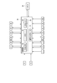
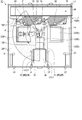
- FIG. 1 is a plan view showing an example of a layout of a cargo handling apparatus according to an embodiment of the present invention.
- FIG. 2 is a block diagram showing parts related to control by the control device.
- FIG. 3 is an enlarged plan view showing an example of the discharge area in FIG.
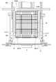
- FIG. 4 is a front view of the discharge area as seen from the direction of the arrow shown in FIG.
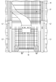
- FIG. 5 is a perspective view illustrating a configuration example of the storage basket.
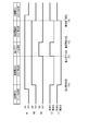
- FIG. 6 is a sequence diagram for explaining an example of control when the storage basket is replaced.
- FIG. 7 is a plan view showing the movable range of the robot arm in the carry-in completed state.
- FIG. 8 is a plan view showing the movable range of the robot arm during the exchange of the storage basket.
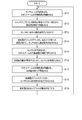
- FIG. 9 is a flowchart illustrating an operation example during a cargo handling operation in the cargo handling apparatus.
- FIG. 10 is a flowchart illustrating an operation example when the storage basket is replaced in the cargo handling device.
- FIG. 1 is a plan view showing an example of a layout of a cargo handling apparatus according to an embodiment of the present invention.
- the cargo handling device 10 includes a robot area 14, two picking areas 12 (# 1) and 12 (# 2) arranged symmetrically around the robot area 14, and two picking areas 12 (# 1) and 12 ( The conveyance area 16 and the discharge area 18 provided in common to # 2) are provided.
- a picking robot (hereinafter simply referred to as “robot”) 20 for picking up parcels such as parcels and parcels is installed.
- the robot 20 functions as a picking unit, and is commonly used in the picking area 12 (# 1) and the picking area 12 (# 2) for loading and unloading work, and is carried into the picking area 12 (# 1).
- the cargo handling work is started in the picking area 12 (# 2).
- an unloading operation (depalletizing) will be described as an example of the cargo handling operation performed by the robot 20.
- the robot 20 can perform not only the unloading operation (depalletizing) but also the loading operation (palletizing) as the cargo handling operation.
- the picking area 12 (# 1) includes a table 22 (# 1) for placing a pallet (not shown) on which a package to be picked by the robot 20 is loaded.
- the picking area 12 (# 2) includes a table 22 (# 2) for placing a similar pallet on which a load picked by the robot 20 is loaded.
- the transfer area 16 is an area for transferring the cargo unloaded from the picking area 12 (# 1) or the picking area 12 (# 2) by the robot 20 to the downstream process, and is unloaded by the robot 20.
- a belt conveyor 24 is provided for conveying the cargo in the direction of the arrow in the figure.
- the robot 20 includes an image sensor (not shown), and this image sensor can detect a nonstandard baggage.
- the discharge area 18 is an area for discharging nonstandard luggage by the robot 20, and a storage basket 26 for storing the nonstandard luggage discharged by the robot 20 is installed.
- the storage bin 26 is configured to be detachable from the discharge area 18, and when a predetermined amount of nonstandard baggage is stored, the storage bin 26 is carried out of the discharge area 18 to be replaced with an empty storage bin 26. Thereafter, an empty storage bin 26 is carried into the discharge area 18 and installed.
- the operator can select the picking area 12 ( When a new load is placed on the table 22 (# 2) in # 2) and the robot 20 finishes the cargo handling work on all the loads on the table 22 (# 1) in the picking area 12 (# 1), picking is performed.
- the seamless transition is made to the cargo handling operation of the luggage already placed on the table 22 (# 2) in the area 12 (# 2).
- the cargo handling apparatus 10 is designed to enable continuous operation of the robot 20 such that the transition to the present cargo handling operation is seamless.
- the cargo handling apparatus 10 includes various sensors S1 to S6, L1 to L5, M1 to M3 ( (Not shown in FIG. 1), safety fences F1 and F2, and a control device 50 (shown in FIG. 1) that performs control according to output signals from the sensors S1 to S6, L1 to L5 and safety fences F1 and F2.
- the interlock mechanism as described below is realized.
- FIG. 2 is a block diagram showing parts related to control by the control device 50.
- FIG. 2 shows the connection relationship between the sensors S1 to S6, L1 to L5, M1 to M3, safety fences F1 and F2, and the robot 20 and the control device 50.
- the control device 50 includes one or a plurality of computers, and includes a communication interface 51, a processor 52, a memory 25, and a storage 54. These can communicate via the bus line 55.
- the control device 50 has an operation terminal (not shown).
- the operation terminal may be a touch panel used for screen display and instruction input to the control device 50, for example.
- the operation terminal may have a display device such as a display and an input device such as a keyboard or a mouse instead of the touch panel.
- the communication interface 51 is an interface that communicates with an external device directly or via a network.
- the communication interface 51 includes terminals and circuits corresponding to the sensors S1 to S6, L1 to L5, M1 to M3, safety fences F1 and F2, and a communication standard for communicating with the robot 20.
- the communication interface 51 communicates with the sensors S1 to S6, L1 to L5, M1 to M3, the safety fences F1 and F2, and the robot 20 based on the control of the processor 52.
- the communication interface 51 reads a control program and various data (hereinafter referred to as a program) stored in a removable storage medium such as a magnetic disk, an optical disk, or a semiconductor memory, that is, a non-transitory computer-readable storage medium. .
- the communication interface 51 communicates with an external server via a network and receives a program and the like from the external server.
- the processor 52 functioning as the center of the computer is constituted by, for example, a CPU (Central Processing Unit).
- the memory 53 as a computer-readable storage medium includes a ROM (Read Only Memory) that is a read-only data memory and a RAM (Random Access Memory) that temporarily stores data.
- the storage 54 as a non-transitory computer-readable storage medium may be a mass storage such as an HDD (Hard Disk Drive) or an SSD (Solid State Drive).
- At least one of the memory 53 (ROM as a non-transitory computer-readable storage medium) and the storage 54 stores a program and the like required for the cargo handling device 10.
- the processor 52 performs various processes based on a program or the like stored in at least one of the memory 53 and the storage 54.
- the processor 52 executes various programs as a software function unit.
- a control circuit such as ASIC (Application Specific Integrated Circuit) or FPGA (Field Programmable Gate Array) as a hardware function unit may be used.
- the communication interface 51 reads a program or the like stored in a removable computer-readable storage medium, or receives a program or the like from an external server, and reads or receives the read program or the like from at least one of the memory 53 and the storage 54. To store.
- the processor 52 completes installation of the program and the like by executing the stored program and the like.
- the sensor S1 is, for example, a laser scanner, and is provided in the picking area 12 (# 1) in order to detect an operator entering the picking area 12 (# 1).
- the sensor S1 outputs a detection signal to the control device 50 when detecting the entry of the operator.
- the sensor S2 is a laser scanner, for example, and is provided in the picking area 12 (# 2) in order to detect entry of an operator into the picking area 12 (# 2).
- the sensor S ⁇ b> 2 outputs a detection signal to the control device 50 when detecting the entry of the operator.
- the sensor S3 is, for example, a laser scanner, and is used to detect an abnormal operation of the robot 20 such as a runaway of the robot arm 21 or the like, and a camera arm 13 (provided above the picking area 12 (# 1)).
- the robot arm 21 is monitored vertically from above, fixed to # 1).
- the sensor S3 outputs a detection signal to the control device 50 when detecting an abnormality in the operation of the robot 20.
- the sensor S4 is, for example, a laser scanner, and is used to detect an abnormal operation of the robot 20 such as a runaway of the robot arm 21 or the like, and a camera arm 13 (provided above the picking area 12 (# 2)).
- the robot arm 21 is monitored vertically from above, fixed to # 2).
- the sensor S ⁇ b> 4 outputs a detection signal to the control device 50 when detecting an abnormality in the operation of the robot 20.
- the sensor S5 is a laser scanner, for example, and is fixed to the camera arm 15 (# 1) provided above in the picking area 12 (# 1), and the operator enters the belt conveyor 24 vertically from above. To detect.
- the sensor S ⁇ b> 5 outputs a detection signal to the control device 50 when detecting the entry of the operator into the belt conveyor 24.
- the sensor S6 is a laser scanner, for example, and is fixed to the camera arm 15 (# 2) provided above the picking area 12 (# 2), and the operator enters the belt conveyor 24 vertically from above. To detect.
- the sensor S ⁇ b> 6 outputs a detection signal to the control device 50 when detecting the operator's entry into the belt conveyor 24.
- the sensor L4 is a pair of light-emitting / receiving sensor units arranged facing the left and right, and is provided at the entrance of the picking area 12 (# 1) in order to detect the entry of the operator into the picking area 12 (# 1).
- a light curtain is formed at the entrance of the picking area 12 (# 1).
- the sensor L4 detects the entry of the operator.
- the sensor L4 outputs a detection signal to the control device 50 when detecting the entry of the operator.
- the sensor L5 is also a pair of light-emitting / receiving sensor units arranged facing the left and right, and in order to detect the operator's entry into the picking area 12 (# 2), the picking area 12 ( A light curtain is formed at the entrance of the picking area 12 (# 2).
- the sensor L5 detects the entry of the operator.
- the sensor L5 outputs a detection signal to the control device 50 when detecting the entry of the operator.
- the safety fence F1 functions as a blocking unit, and when the robot 20 operates in the picking area 12 (# 1), the robot 20 and the picking area are prevented so that the operation of the robot 20 does not reach the picking area 12 (# 2).
- 12 (# 2) is an open / close fence.
- the safety fence F2 functions as a blocking unit, and when the robot 20 operates in the picking area 12 (# 2), the robot 20 and the picking area are prevented from reaching the picking area 12 (# 1).
- 12 (# 1) is an open / close fence.
- the safety fence F1 opens and closes in response to, for example, an operation button pressed by an operator.
- FIG. 1 shows that the safety fence F1 is in a closed state (a state where the robot 20 and the picking area 12 (# 2) are blocked), and the safety fence F2 is in an opened state (the robot 20 and the picking area 12 (# 1)). It is in a state of not blocking.
- the safety fences F1 and F2 are provided with sensors (not shown) for detecting the closed state of the safety fences F1 and F2. These sensors (not shown) indicate the closed state when the closed state of the safety fence is detected.
- the closed state signal is output to the control device 50.
- a closed state signal is transmitted from the safety fences F1 and F2 to the control device 50 instead of a sensor (not shown) as shown in FIG.
- the processor 52 of the control device 50 enables the sensors S1, L4, S4, and S6, and the sensors S2, L5, S3 and S5 are invalidated, and the operation of the robot 20 in the picking area 12 (# 1) is permitted.
- the processor 52 of the control device 50 enables the sensors S2, L5, S3, and S5, L4, S4, and S5 are invalidated, and the operation of the robot 20 in the picking area 12 (# 2) is permitted.
- the robot 20 lifts the loads placed on the table 22 one by one in the picking area 12 permitted to operate, rotates the robot arm 21 to the transfer area 16, and then loads the loads on the belt conveyor 24. Placed on.
- the belt conveyor 24 conveys the cargo to the downstream process by proceeding in the direction of the arrow in the figure.
- a sensor L1 is provided on the downstream side of the belt conveyor 24. When an operator enters from the belt conveyor 24 side, the sensor L1 detects the operator's entry and outputs a detection signal to the control device 50.
- the robot 20 when the robot 20 detects such a nonstandard baggage using an image sensor (not shown), the robot 20 rotates the robot arm 21 to the discharge area 18 while lifting the nonstandard baggage, and then discharges the baggage to the discharge area 18.
- the processor 52 of the control device 50 operates the robot 20 according to the operator's operation. Switching control for switching the picking area 12 is performed, and the operation of the robot 20 in the other picking area 12 is permitted. Thereafter, the robot 20 performs the cargo handling operation as described above in the permitted picking area 12.
- the safety fence F1 is opened according to the pressing of the operation button by the operator, and the safety fence
- the processor 52 of the control device 50 validates the sensors S2 and L5 and invalidates the sensors S4 and S6. Thereafter, the safety fence F2 is closed in response to pressing of the operation button by the operator, and when the closed state signal is output from the safety fence F2, the processor 52 of the control device 50 activates the sensors S3 and S5, Disable L4.
- the safety fence F2 is opened in accordance with the pressing of the operation button by the operator,
- the processor 52 of the control device 50 enables the sensors S1 and L4 and disables the sensors S3 and S5.
- the safety fence F1 is closed in response to the pressing of the operation button by the operator, and when the closed state signal is output from the safety fence F1, the processor 52 of the control device 50 activates the sensors S4 and S6, Disable L5.
- the processor 52 of the control device 50 does not permit the operation of the robot 20 when a detection signal is output from any of the sensors S1 to S6 and L4 to L5 that are enabled. In particular, when a detection signal is output from any of the sensors S1 to S6 and L4 to L5 that are enabled during the operation of the robot 20, the operation of the robot 20 is stopped.
- the discharge area 18 is an area for discharging nonstandard luggage as described above, the discharge area 18 stores a predetermined amount of discharged nonstandard luggage at the timing when the nonstandard luggage is discharged.
- the replacement timing of the storage basket 26 is irregular, and is not necessarily linked with the switching timing of the picking area 12 described above.
- FIG. 3 is an enlarged plan view showing an example of the discharge area 18 in FIG.
- FIG. 4 is a front view of the discharge area 18 as seen from the direction of the arrow shown in FIG.
- a storage basket 26 for storing nonstandard baggage discharged by the robot 20 is installed.
- FIG. 5 is a perspective view showing a configuration example of the storage bowl 26.
- the arrow direction shown in the figure corresponds to the arrow direction in FIG.
- the discharge area 18 includes a fence 27 on the front surface, and further includes sensors L2, L3, and M1 to M3 inside.
- the fence 27 is opened when the storage basket 26 is carried into the discharge area 18 and when the storage basket 26 is carried out from the discharge area 18, and is closed in other cases.
- the sensor L2 is a pair of light-emitting / receiving sensor units that are disposed facing left and right, and can detect the storage rod 26 that is carried into the discharge area 18 or discharged from the discharge area 18. Arranged to form a light curtain over the height. Accordingly, when the storage basket 26 is carried into the discharge area 18 and unloaded from the discharge area 18 at an unintended timing, the light curtain is blocked, and the sensor L2 detects the detection signal accordingly. Is output to the control device 50.
- the sensor L3 is also a pair of light-emitting / receiving sensor units that are disposed to face in the left-right direction, and forms a light curtain at a position higher than the sensor L2 so that an operator's entry into the discharge area 18 can be detected.
- the sensor L3 outputs a detection signal to the control device 50 accordingly.
- the sensor M1 is, for example, a light reflection sensor, and is provided in the lower right front part of the discharge area 18, and outputs a detection signal to the control device 50 when light reflection from the storage basket 26 is detected.
- the sensor M2 is, for example, a light reflection sensor, and is provided in the lower left part of the front side of the discharge area 18, and outputs a detection signal to the control device 50 when light reflection from the storage bowl 26 is detected.
- the sensor M3 is, for example, a light reflection sensor, and is provided at the lower left lower portion of the discharge area 18, and outputs a detection signal to the control device 50 when light reflection from the storage basket 26 is detected.
- the storage trough 26 has a substantially rectangular parallelepiped shape, and is fixed so as to stand upright on the rectangular bottom 32 raised by the four corner projections 31 (# 1 to # 4) and the four sides of the bottom 32, respectively.
- a nonstandard baggage is stored in a space formed by the two side portions 33 (# 1 to # 4) and surrounded by the four side portions 33 (# 1 to # 4).
- the left side portion 33 (# 4) is loaded with non-standard loads from the picking area 12 (# 1) by the robot arm 21, and the right side portion 33 (# 3) is picked up by the robot arm 21 with the picking area 12 (##). Since non-standard load is carried from 2), it is lower than the front side portion 33 (# 1) and the back side portion 33 (# 2).
- reinforcing plates 34 (# 1 to # 4) each having a predetermined shape are provided at predetermined locations at the four corners of the bottom 32.
- the reinforcing plates 34 (# 1 to # 4) ensure the strength of the storage rod 26 and also function as a reflecting plate that reflects light from the sensors M1 to M3 that are light reflecting sensors.
- the storage rod 26 is installed in the discharge area 18 by carrying the storage rod 26 jacked up outside the discharge area 18 into the discharge area 18 and moving it to the vicinity of the fixing groove provided in the discharge area 18. This is done by jacking down so that the four protrusions 31 (# 1 to # 4) are fitted in the groove.
- the sensors M1 and M2 detect light reflection from the reinforcing plates 34 (# 1) and (# 2) when the storage basket 26 is moved to the vicinity of the fixed groove in the discharge area 18, and control the detection signal. Output to 50.
- the sensor M3 detects light reflection from the reinforcing plate 34 (# 3) when the protrusion 31 (# 1 to # 4) of the storage basket 26 is fitted in the fixed groove in the discharge area 18, and detects the detection.
- the signal is output to the control device 50.
- the storage basket 26 is configured to be detachable from the discharge area 18.
- the storage basket 26 is replaced with an empty storage basket 26. Therefore, it is carried out from the discharge area 18. Thereafter, an empty storage bin 26 is carried into and installed in the discharge area 18. Thus, the storage basket 26 is replaced in the discharge area 18.
- FIG. 6 is a sequence diagram for explaining an example of control when the storage bowl 26 is replaced.
- the carry-in completion state T1 shown in FIG. 6 corresponds to a state in which the storage bin 26 is correctly installed in the discharge area 18.
- the processor 52 of the control device 50 validates the sensor L2 and invalidates the sensor L3.
- any of the sensors M1 to M3 outputs a detection signal to the control device 50.
- FIG. 7 is a plan view showing the movable range R of the robot arm 21 in the loading completion state T1.
- FIG. 8 is a plan view showing the movable range R of the robot arm 21 during the exchange of the storage bowl 26.
- the robot arm 21 when the robot 20 is operating in the picking area 12 (# 1), when the carry-in completion state T1 is reached, as shown in FIG. Then, the robot arm 21 is rotated to the discharge area 18 side, and the nonstandard baggage is discharged into the storage basket 26. As described above, the robot arm 21 can unload the lifted baggage onto the belt conveyor 24 if it is within the standard and discharge it to the storage basket 26 if it is out of the standard. Can be rotated inside.
- the processor 52 of the control device 50 activates the sensor L3 in response to an operator operation in order to carry out the storage basket 26 from the discharge area 18.
- the sensor L2 is invalidated while being invalidated.
- the timing which carries out the storage container 26 from the discharge area 18 is made by operator judgment, for example. Therefore, the unloading start state T2 is not necessarily a state where the storage bag 26 is fully loaded with nonstandard luggage.
- the processor 52 of the control device 50 limits the movable range R of the robot arm 21, and the robot arm 21 moves to the discharge area 18 while the storage basket 26 is being carried out from the discharge area 18. Do not reach.
- the storage trough 26 When the storage trough 26 is carried out from the discharge area 18, contrary to the case where the storage trough 26 is installed in the discharge area 18, first, the storage trough 26 installed in the discharge area 18 is jacked up so that the protruding portion The fitting of 31 (# 1 to # 4) into the fixing groove is released. As a result, no detection signal is output from the sensor M3 to the control device 50. On the other hand, even if the projections 31 (# 1 to # 4) are released from fitting into the fixing grooves, the detection signals from the sensors M1 and M2 continue to the control device 50 as long as the storage rod 26 is in the vicinity of the fixing grooves. Is output.
- the storage basket 26 is pulled out from the discharge area 18 while being jacked up, whereby the carry-out of the storage basket 26 from the discharge area 18 is completed.
- no detection signal is output from the sensors M1 and M2 to the control device 50.
- This state is referred to as an unloading completion state T3.
- the processor 52 of the control device 50 validates the sensors L2 and L3 in response to the detection signals not being output from the sensors M1 and M2.
- the timing at which the detection signals from the sensors M1 and M2 are not output to the control device 50 may not match between the sensor M1 and the sensor M2. Therefore, the processor 52 of the control device 50 determines that the unloading completion state T3 has been reached at the timing when the detection signal is no longer output from either the sensor M1 or the sensor M2, and validates the sensors L2 and L3.
- the operator When the carry-in start state T4 is reached, since the sensors L2 and L3 are invalidated, the operator carries the empty storage trough 26 into the discharge area 18 while being jacked up, and is provided in the discharge area 18. It can be moved to the vicinity of the fixed groove. Accordingly, the sensors M1 and M2 detect reflection from the reinforcing plates 34 (# 1) and (# 2), and output detection signals to the control device 50. In practice, as shown in FIG. 6, the timing at which detection signals start to be output from the sensors M1 and M2 to the control device 50 may not match between the sensor M1 and the sensor M2. Therefore, the control device 50 determines that the loading start completion state T4 has been reached at the timing when the detection signals are output from both the sensors M1 and M2.
- the operator jacks down the empty storage trough 26 and fits the four protrusions 31 (# 1 to # 4) in the fixing groove in the discharge area 18. Accordingly, the sensor M3 detects reflection from the reinforcing plate 34 (# 3), and outputs a detection signal to the control device 50.
- the processor 52 of the control device 50 validates the sensor L2 while invalidating the sensor L3. As a result, the carry-in completion state T1 described above is obtained.
- the processor 52 of the control device 50 releases the restriction on the movable range R of the robot arm 21, and the movable range R becomes as shown in FIG.
- the cargo handling apparatus 10 replaces the storage basket 26 while ensuring the safety of the operator.
- FIG. 9 is a flowchart showing an example of the operation at the time of cargo handling work in the cargo handling device 10.
- a pallet (not shown) on which a load is loaded is placed on the table 22 (# 1) of the picking area 12 (# 1), so that the load is brought into the picking area 12 (# 1). (ST1).
- the robot 20 is permitted to operate in the picking area 12 (# 1) by the processor 52 of the control device 50. Therefore, the load loaded on the pallet placed on the table 22 (# 1) is lifted by the robot 20, and the robot arm 21 is rotated toward the transfer area 16, and onto the belt conveyor 24 in the transfer area 16.
- the unloading work to be unloaded that is, the unloading work (depalletizing) is performed (ST2).
- the sensors S3 to S6 are disabled, but the sensors S1, S2, L4, and L5 on the entrance side of the picking area 12 are enabled, and the operator can select the picking area 12 (# 1), ( When trying to enter # 2), it is detected by any of the sensors S 1, S 2, L 4 and L 5, and a detection signal is output to the control device 50. In this case, the operation of the robot 20 is stopped by the processor 52 of the control device 50.
- the sensors S4 and S6 are validated and the sensors S2 and L5 are invalidated by the processor 52 of the control device 50 (ST4).
- the operator can enter the picking area 12 (# 2). Accordingly, during this time, the operator enters the picking area 12 (# 2) and places a pallet (not shown) on which the load is loaded on the table 22 (# 2), thereby picking the area 12 (#). 2) Carry in the package (ST5).
- the robot 20 still continues the cargo handling work in the picking area 12 (# 1). However, since the safety fence F1 is closed, the operation of the robot 20 does not reach the picking area 12 (# 2). Since there is no contact accident between the robot 20 and the operator carrying the load into the picking area 12 (# 2), the operator's safety is ensured.
- the abnormality in the operation of the robot 20 is detected by the sensor S 4 because the sensor S 4 is valid.
- the detection signal is output from the sensor S4 to the control device 50.
- the operation of the robot 20 is stopped by the processor 52 of the control device 50, so that the safety of the operator is ensured.
- the operator leaves the picking area 12 (# 2) and presses an operation button (not shown) to open the safety fence F1 (ST6). Accordingly, the closed state signal is not output from the safety fence F1 to the control device 50.
- the sensors S2 and L5 are validated and the sensors S4 and S6 are invalidated by the processor 52 of the control device 50 (ST7).
- the sensors S2 and L5 are also activated, so that even if the operator tries to enter the picking areas 12 (# 1) and (# 2), the sensor Detection is performed by any one of S1, S2, L4, and L5, and a detection signal is output to the control device 50.
- the processor 52 of the control device 50 stops the operation of the robot 20.
- the robot 20 When the handling operation by the robot 20 in the picking area 12 (# 1) is completed (ST8), the robot 20 is permitted to operate in the picking area 12 (# 2) by the processor 52 of the control device 50 in response to an operator operation. (ST9), returning to the operation of step ST2, the load loaded on the pallet placed on the table 22 (# 2) is lifted by the robot 20, and the robot arm 21 is rotated to the transfer area 16 side. The cargo handling work is performed by unloading onto the belt conveyor 24.
- the safety fence F1 in the description of the above-described steps ST2 to ST9 is the safety fence F2, and the sensors S2, L5, S4, and S6. Should be understood as sensors S1, L4, S3, and S5, respectively.
- the cargo handling device 10 while the cargo handling operation is being performed by the robot 20 in one picking area 12, the operator can carry in the cargo to the other picking area 12, and the operator's safety can be increased. It becomes possible to carry out while ensuring. That is, the cargo handling apparatus 10 can achieve both high work efficiency and high safety.
- the robot 20 is provided with an image sensor (not shown).
- the robot arm 21 is rotated to the discharge area 18 side, and the storage basket 26 installed in the discharge area 18 is out of specification. Discharge the package.
- the storage basket 26 is carried out from the discharge area 18, and the empty storage basket 26 is installed in the discharge area 18, thereby replacing the storage basket 26.
- FIG. 10 is a flowchart showing an operation example when the storage basket is replaced in the cargo handling device 10.
- the storage trough 26 is jacked up outside the discharge area 18 and is carried into the discharge area 18 and moved to the vicinity of the fixed groove provided in the discharge area 18 (ST12). Then, light reflection from the reinforcing plates 34 (# 1) and (# 2) is detected by the sensors M1 and M2, and a detection signal is output to the control device 50 (ST13).
- the storage trough 26 is jacked down so that the four protrusions 31 (# 1 to # 4) are fitted in the fixing grooves in the discharge area 18.
- the installation of the storage basket 26 in the discharge area 18 is completed, the light reflection from the reinforcing plate 34 (# 3) is detected by the sensor M3, and a detection signal is output to the control device 50 (ST14).
- the sensor L2 is activated by the processor 52 of the control device 50, and the restriction on the movable range R of the robot arm 21 is released as shown in FIG. 7 (ST15).
- the movable range R of the robot arm 21 is limited as shown in FIG. 8 by the processor 52 of the control device 50, and the storage basket 26 can be carried out from the discharge area 18 (ST17).
- the procedure for unloading the storage bin 26 from the discharge area 18 is the reverse of the procedure for installing the storage bin 26 in the discharge area 18. That is, by jacking up the storage rod 26 installed in the discharge area 18, the fitting of the protrusions 31 (# 1 to # 4) into the fixing groove is released. As a result, the detection signal from the sensor M3 is not output to the control device 50. On the other hand, even if the protrusions 31 (# 1 to # 4) are released from fitting into the fixed groove, the detection signals from the sensors M1 and M2 continue to be detected as long as the storage rod 26 is in the vicinity of the fixed groove. 50 (ST18).
- the storage trough 26 is pulled out from the discharge area 18 with the storage trough 26 being jacked up to complete the carry-out of the storage trough 26 from the discharge area 18 (ST19).
- no detection signal is output from the sensors M1 and M2 to the control device 50.
- the sensors L2 and L3 are activated by the processor 52 of the control device 50 in response to the fact that the detection signals are not output from the sensors M1 and M2.
- the process returns to step S11, and as described above, the empty storage bin 26 is carried into the discharge area 18 and installed.
- the case where the robot 20 operates in the picking area 12 (# 1) has been described as an example, but the case where the robot 20 operates in the picking area 12 (# 2) is also described in the same manner.
- the storage basket 26 is exchanged during the cargo handling operation of the robot 20, so that the cargo handling device 10 can discharge nonstandard luggage without reducing the work efficiency of the robot 20. Moreover, since the movable range R of the robot arm 21 is limited so that the operation of the robot arm 21 does not reach the discharge area 18 during the exchange of the storage rod 26, the operator's safety can be ensured.
- the operator can carry in the cargo while ensuring the safety of the operator, and thus the safety is excellent. Therefore, it is possible to provide a cargo handling device 10 that does not cause a decrease in cargo handling work efficiency, its control device 50, and a control method and program implemented in the control device 50.
- the unloading work has been described as an example of the cargo handling work.
- the cargo handling apparatus 10 according to the embodiment is applicable not only to unloading work (depalletizing) but also to loading work (palletizing).
Landscapes
- Engineering & Computer Science (AREA)
- Mechanical Engineering (AREA)
- Warehouses Or Storage Devices (AREA)
Abstract
実施形態によれば、荷役装置は、ピッキング部と、第1のエリアへの人の立ち入りを検出する第1のセンサと、第2のエリアへの人の立ち入りを検出する第2のセンサと、ピッキング部と第2のエリアとを遮る第1の遮断部と、ピッキング部と第1のエリアとを遮る第2の遮断部と、第1の遮断部によって遮られている場合、第1のセンサを有効化し、第2のセンサを無効化し、ピッキング部の第1のエリアにおける動作を許可する一方、第2の遮断部によって遮られている場合、第2のセンサを有効化し、第1のセンサを無効化し、ピッキング部の第2のエリアにおける動作を許可する制御部とを備えている。
Description
本発明の実施形態は、荷物の荷降し作業(デパレタイズ)および荷積み作業(パレタイズ)を含む荷役作業のための荷役装置、その制御装置、制御方法、およびコンピュータ可読記憶媒体に関する。
従来、物流センター等では、集積された荷物を、ピッキングロボットによって、ベルトコンベア等が備えられた搬送エリアへ荷降す作業(デパレタイズ)や、箱へ荷積みする作業(パレタイズ)といった荷役作業のために荷役装置が導入されている。
この種の荷役装置では、荷役作業効率の向上を図るために、ピッキングロボットの動作を不連続にしないこと、言い換えると、ピッキングロボットに常に作業をさせていることが好ましい。特許文献1には、ピッキングロボットの荷役作業効率の向上のための技術が開示されている。
例えば、デバレタイズの場合、ピッキングロボットによって荷役作業される荷物は、オペレータが荷役装置内に立ち入ることによって、荷役装置に搬入される。
しかしながら、荷役作業される荷物の搬入のために、ピッキングロボットの動作中に、オペレータが荷役装置内に立ち入ることは、オペレータのピッキングロボットとの接触事故の恐れもあり、オペレータの安全性確保の観点から好ましくはない。
したがって、従来の荷役装置では、オペレータによる荷物の搬入作業中は、ピッキングロボットの動作が停止されている。
しかしながら、ピッキングロボットの動作を停止させることは、荷役作業効率の低下を招く。
本発明が解決しようとする課題は、ピッキングロボットによる荷役作業中であっても、オペレータの安全を確保しつつ、オペレータによる荷物の搬入作業を可能にすることによって、安全性に優れ、かつ、荷役作業効率の低下を招くこともない荷役装置、その制御装置、制御方法、およびコンピュータ可読記憶媒体を提供することである。
実施形態の荷役装置は、荷物のピッキングのために、予め指定された第1のエリアおよび第2のエリアにおいて使用されるピッキング部と、第1のエリアへの人の立ち入りを検出する第1のセンサと、第2のエリアへの人の立ち入りを検出する第2のセンサと、ピッキング部の動作が、第2のエリアに及ばないように、ピッキング部と第2のエリアとを遮る第1の遮断部と、ピッキング部の動作が、第1のエリアに及ばないように、ピッキング部と第1のエリアとを遮る第2の遮断部と、前記ピッキング部が第1の遮断部によって遮られ、第2の遮断部によって遮られていない場合、第1のセンサを有効化し、第2のセンサを無効化し、ピッキング部の第1のエリアにおける動作を許可する一方、前記ピッキング部が第2の遮断部によって遮られ、第1の遮断部によって遮られていない場合、第2のセンサを有効化し、第1のセンサを無効化し、ピッキング部の第2のエリアにおける動作を許可する制御部とを備えている。
以下に、本発明の実施形態の荷役装置を、図面を参照して説明する。
図1は、本発明の実施形態の荷役装置のレイアウトの一例を示す平面図である。
荷役装置10は、ロボットエリア14と、ロボットエリア14を中心として対称に配置された2つのピッキングエリア12(#1)、12(#2)と、2つのピッキングエリア12(#1)、12(#2)に共通して設けられた搬送エリア16および排出エリア18を備える。
ロボットエリア14には、宅配物や、小包のような荷物のピッキングのためのピッキングロボット(以下、単に「ロボット」と称する)20を設置している。
ロボット20は、ピッキング部として機能し、荷物の荷役作業のために、ピッキングエリア12(#1)およびピッキングエリア12(#2)において共通して使用され、ピッキングエリア12(#1)に搬入された荷物に対する荷役作業を完了させると、次にピッキングエリア12(#2)において荷役作業を開始する。なお、以下の説明では、ロボット20によって行われる荷役作業として、荷降し作業(デパレタイズ)を例に挙げて説明する。しかしながら、ロボット20は、荷役作業として、荷降し作業(デパレタイズ)のみならず、荷積み作業(パレタイズ)も同様に行うことができる。
ピッキングエリア12(#1)は、ロボット20によってピッキングされる荷物が積載されたパレット(図示せず)を載置するためのテーブル22(#1)を備えている。同様に、ピッキングエリア12(#2)は、ロボット20によってピッキングされる荷物が積載された同様のパレットを載置するためのテーブル22(#2)を備えている。
搬送エリア16は、ロボット20によって、ピッキングエリア12(#1)またはピッキングエリア12(#2)から荷降しされた荷物を下流工程へ搬送するためのエリアであり、ロボット20によって荷降しされた荷物を、図中矢印方向へ搬送するベルトコンベア24を備えている。
ロボット20が荷降しする荷物の中には、規格外サイズの荷物のように、荷役装置10で取り扱い可能な規格に準拠しない荷物もあり得る。ロボット20は、図示しない画像センサを備えており、この画像センサによって、規格外荷物を検知することができる。そして、規格外荷物を検知すると、検知した規格外荷物を、排出エリア18へ排出する。すなわち、排出エリア18は、ロボット20により規格外荷物が排出されるためのエリアであり、ロボット20によって排出された規格外荷物を収納するための収納籠26が設置される。
収納籠26は、排出エリア18に着脱可能な構成となっており、規格外荷物を所定量収納すると、空の収納籠26と交換されるために、排出エリア18から搬出される。その後、排出エリア18には、空の収納籠26が搬入され、設置される。
荷役装置10によれば、例えば、ロボット20が、ピッキングエリア12(#1)のテーブル22(#1)に載置された荷物の荷役作業を行っている間に、オペレータが、ピッキングエリア12(#2)のテーブル22(#2)へ新たな荷物を載置し、ロボット20が、ピッキングエリア12(#1)のテーブル22(#1)上のすべての荷物の荷役作業を終了すると、ピッキングエリア12(#2)のテーブル22(#2)上に既に載置されている荷物の荷役作業へとシームレスに移行する。
一方、オペレータは、ピッキングエリア12(#2)におけるロボット20による荷役作業中に、ピッキングエリア12(#1)のテーブル22(#1)上へ新たな荷物を載置する。これによって、ロボット20は、ピッキングエリア12(#2)のテーブル22(#2)上のすべての荷物の荷役作業を終了すると、ピッキングエリア12(#1)のテーブル22(#1)上の荷物の荷役作業へシームレスに移行するという具合に、荷役装置10は、ロボット20の連続的な動作を可能にするように設計されている。
このようなロボット20の連続的な動作を、荷物の搬入を行うオペレータの安全性を確保しつつ達成するために、荷役装置10は、種々のセンサS1~S6、L1~L5、M1~M3(図1に図示されず)と、安全フェンスF1、F2と、各センサS1~S6、L1~L5および安全フェンスF1、F2からの出力信号に応じた制御を行う制御装置50(図1に図示されず)とを備えることによって、以下に説明するようなインターロックメカニズムを実現している。
図2は、制御装置50による制御に関連する部位を示すブロック図である。図2は、各センサS1~S6、L1~L5、M1~M3、安全フェンスF1、F2、およびロボット20と制御装置50との接続関係を示している。また、制御装置50は、1又は複数台のコンピュータにより構成され、通信インタフェース51と、プロセッサ52と、メモリ25と、ストレージ54とを有している。これらは、バスライン55を介して通信可能である。また、制御装置50は、図示しない操作端末を有している。操作端末は、例えば、画面表示と制御装置50への指示入力とに用いられるタッチパネルであってよい。操作端末は、タッチパネルに代わって、ディスプレイなどの表示装置とキーボード又はマウスなどの入力装置とを有してもよい。
通信インタフェース51は、直接又はネットワーク経由で外部機器と通信するインタフェースである。通信インタフェース51は、各センサS1~S6、L1~L5、M1~M3、安全フェンスF1、F2、およびロボット20と通信するための通信規格などに対応した端子及び回路を備える。通信インタフェース51は、プロセッサ52の制御に基づいて、各センサS1~S6、L1~L5、M1~M3、安全フェンスF1、F2、およびロボット20と通信する。また、通信インタフェース51は、磁気ディスク、光ディスク、又は半導体メモリなどのようなリムーバブルな記憶媒体、即ち非一時的なコンピュータ可読記憶媒体に記憶された制御プログラム及び各種データ(以下、プログラム等)を読み出す。さらに、通信インタフェース51は、ネットワーク経由で外部サーバと通信し、外部サーバからプログラム等を受信する。
コンピュータの中枢として機能するプロセッサ52は、例えば、CPU(Central Processing Unit)により構成される。コンピュータ可読記憶媒体としてのメモリ53は、読み出し専用のデータメモリであるROM(Read Only Memory)及びデータを一時的に記憶するRAM(Random Access Memory)を含む。非一時的なコンピュータ可読記憶媒体としてのストレージ54は、HDD(Hard Disk Drive)又はSSD(Solid State Drive)などの大容量ストレージであってよい。メモリ53(非一時的なコンピュータ可読記憶媒体としてのROM)及びストレージ54の少なくとも一方は、荷役装置10で必要とされるプログラム等を記憶している。プロセッサ52は、メモリ53及びストレージ54の少なくとも一方に記憶されているプログラム等に基づいて種々の処理を行う。つまり、プロセッサ52は、ソフトウェア機能部として各種プログラムを実行する。プロセッサ52に代わって、ハードウェア機能部としてのASIC(Application Specific Integrated Circuit)又はFPGA(Field Programmable Gate Array)などの制御回路が用いられてもよい。例えば、通信インタフェース51は、リムーバブルなコンピュータ可読記憶媒体に記憶されたプログラム等を読み出して、或いは、外部サーバからプログラム等を受信し、読み出した又は受信したプログラム等をメモリ53及びストレージ54の少なくとも一方に格納する。プロセッサ52は、格納されたプログラム等を実行することにより、プログラム等のインストールを完了する。
続いて、制御装置50に接続される機器について説明する。センサS1は、例えばレーザースキャナであって、ピッキングエリア12(#1)へのオペレータの立ち入りを検出するために、ピッキングエリア12(#1)内に設けられる。センサS1は、オペレータの立ち入りを検出すると、検出信号を、制御装置50へ出力する。
センサS2は、例えばレーザースキャナであって、ピッキングエリア12(#2)へのオペレータの立ち入りを検出するために、ピッキングエリア12(#2)内に設けられる。センサS2は、オペレータの立ち入りを検出すると、検出信号を、制御装置50へ出力する。
センサS3は、例えばレーザースキャナであって、ロボットアーム21の暴走等のようなロボット20の動作の異常を検出するために、ピッキングエリア12(#1)内の上方に設けられたカメラアーム13(#1)に固定され、上方から垂直に、ロボットアーム21を監視する。センサS3は、ロボット20の動作の異常を検出すると、検出信号を、制御装置50へ出力する。
センサS4は、例えばレーザースキャナであって、ロボットアーム21の暴走等のようなロボット20の動作の異常を検出するために、ピッキングエリア12(#2)内の上方に設けられたカメラアーム13(#2)に固定され、上方から垂直に、ロボットアーム21を監視する。センサS4は、ロボット20の動作の異常を検出すると、検出信号を、制御装置50へ出力する。
センサS5は、例えばレーザースキャナであって、ピッキングエリア12(#1)内の上方に設けられたカメラアーム15(#1)に固定され、上方から垂直に、ベルトコンベア24へのオペレータの立ち入りを検出する。センサS5は、ベルトコンベア24へのオペレータの立ち入りを検出すると、検出信号を、制御装置50へ出力する。
センサS6は、例えばレーザースキャナであって、ピッキングエリア12(#2)内の上方に設けられたカメラアーム15(#2)に固定され、上方から垂直に、ベルトコンベア24へのオペレータの立ち入りを検出する。センサS6は、ベルトコンベア24へのオペレータの立ち入りを検出すると、検出信号を、制御装置50へ出力する。
センサL4は、左右に対向して配置された一対の発光受光センサユニットであって、ピッキングエリア12(#1)へのオペレータの立ち入りを検出するために、ピッキングエリア12(#1)の入口に設けられ、ピッキングエリア12(#1)の入口に光カーテンを形成する。オペレータがピッキングエリア12(#1)の入口からピッキングエリア12(#1)内へ立ち入ると、オペレータによって光カーテンが遮られるために、センサL4は、オペレータの立ち入りを検出する。センサL4は、オペレータの立ち入りを検出すると、検出信号を、制御装置50へ出力する。
センサL5も、センサL4と同様に、左右に対向して配置された一対の発光受光センサユニットであって、ピッキングエリア12(#2)へのオペレータの立ち入りを検出するために、ピッキングエリア12(#2)の入口に設けられ、ピッキングエリア12(#2)の入口に光カーテンを形成する。オペレータがピッキングエリア12(#2)の入口からピッキングエリア12(#2)内へ立ち入ると、オペレータによって光カーテンが遮られるために、センサL5は、オペレータの立ち入りを検出する。センサL5は、オペレータの立ち入りを検出すると、検出信号を、制御装置50へ出力する。
安全フェンスF1は、遮断部として機能し、ロボット20がピッキングエリア12(#1)において動作する場合、ロボット20の動作が、ピッキングエリア12(#2)に及ばないように、ロボット20とピッキングエリア12(#2)とを遮るための開閉式のフェンスである。
安全フェンスF2は、遮断部として機能し、ロボット20がピッキングエリア12(#2)において動作する場合、ロボット20の動作が、ピッキングエリア12(#1)に及ばないように、ロボット20とピッキングエリア12(#1)とを遮るための開閉式のフェンスである。
安全フェンスF1は、例えばオペレータによる動作ボタンの押圧に応じて、開閉動作を行う。図1は、安全フェンスF1が、閉状態(ロボット20とピッキングエリア12(#2)とを遮る状態)にあり、安全フェンスF2が、開状態(ロボット20とピッキングエリア12(#1)とを遮らない状態)にあることを示している。
安全フェンスF1、F2には、安全フェンスF1、F2の閉状態を検知するセンサ(図示せず)が設けられており、これら図示しないセンサは、安全フェンスの閉状態を検知すると、閉状態を示す閉状態信号を、制御装置50へ出力する。なお、本明細書では、簡略のために、図2に示すように、図示しないセンサではなく、安全フェンスF1、F2から、制御装置50へ閉状態信号が送信されるものとして説明する。
制御装置50のプロセッサ52は、安全フェンスF1から閉状態信号が出力され、安全フェンスF2から閉状態信号が出力されていない場合、センサS1、L4、S4、S6を有効化し、センサS2、L5、S3、S5を無効化し、ロボット20のピッキングエリア12(#1)における動作を許可する。
一方、制御装置50のプロセッサ52は、安全フェンスF2から閉状態信号が出力され、安全フェンスF1から閉状態信号が出力されていない場合、センサS2、L5、S3、S5を有効化し、センサS1、L4、S4、S5を無効化し、ロボット20のピッキングエリア12(#2)における動作を許可する。
ロボット20は、動作を許可されたピッキングエリア12において、テーブル22上に載置されている荷物を、1つずつ持ち上げ、ロボットアーム21を搬送エリア16まで回転させた後に、荷物をベルトコンベア24上に載置する。
ベルトコンベア24は、図中矢印方向に進むことによって、荷物を下流工程へ搬送する。
ベルトコンベア24の下流側には、センサL1が設けられている。ベルトコンベア24側からのオペレータの進入があると、センサL1はそのオペレータの進入を検知し、検知信号を、制御装置50へ出力する。
また、前述したように、ロボット20が荷降しする荷物の中には、規格外サイズの荷物のように、荷役装置10で取り扱い可能な規格に準拠しない荷物もあり得る。ロボット20は、図示しない画像センサによって、このような規格外荷物を検知すると、規格外荷物を持ち上げたまま、ロボットアーム21を排出エリア18まで回転させた後に、荷物を排出エリア18へ排出する。
このようにして、ロボット20が、動作を許可された一方のピッキングエリア12において、すべての荷物の荷役作業を完了すると、制御装置50のプロセッサ52は、オペレータ操作に応じて、ロボット20の動作するピッキングエリア12を切り替えるための切替制御を行い、他方のピッキングエリア12におけるロボット20の動作を許可する。その後、ロボット20は、許可されたピッキングエリア12において、前述したような荷役作業を行う。
例えば、ロボット20が動作するピッキングエリア12を、ピッキングエリア12(#1)から、ピッキングエリア12(#2)へ切り替える場合、オペレータによる動作ボタンの押圧に応じて、安全フェンスF1を開き、安全フェンスF1から、閉状態信号が出力されなくなると、制御装置50のプロセッサ52は、センサS2、L5を有効化し、センサS4、S6を無効化する。その後、オペレータによる動作ボタンの押圧に応じて、安全フェンスF2を閉じ、安全フェンスF2から閉状態信号が出力されると、制御装置50のプロセッサ52は、センサS3、S5を有効化し、センサS1、L4を無効化する。
逆に、ロボット20が動作するピッキングエリア12を、ピッキングエリア12(#2)から、ピッキングエリア12(#1)へ切り替える場合、オペレータによる動作ボタンの押圧に応じて、安全フェンスF2を開き、安全フェンスF2から閉状態信号が出力されなくなると、制御装置50のプロセッサ52は、センサS1、L4を有効化し、センサS3、S5を無効化する。その後、オペレータによる動作ボタンの押圧に応じて、安全フェンスF1を閉じ、安全フェンスF1から閉状態信号が出力されると、制御装置50のプロセッサ52は、センサS4、S6を有効化し、センサS2、L5を無効化する。
制御装置50のプロセッサ52は、センサS1~S6、L4~L5のうち、有効化されている何れかのセンサから検出信号が出力された場合、ロボット20の動作を許可しない。特に、ロボット20の動作中に、センサS1~S6、L4~L5のうち、有効化されている何れかのセンサから検出信号が出力された場合、ロボット20の動作を停止させる。
このような制御は、ロボット20による荷役作業中であっても、オペレータの安全を確保しつつ、オペレータによる荷物の搬入作業を可能にする。
次に、排出エリア18における収納籠26の交換について説明する。排出エリア18は、前述したように、規格外荷物が排出されるためのエリアであるので、排出エリア18へ規格外荷物が排出されるタイミング、および、排出された規格外荷物を所定量収納している収納籠26が交換されるタイミングはともに不規則であり、前述したピッキングエリア12の切替のタイミングとは必ずしも連動しない。
図3は、図1における排出エリア18の一例を示す拡大平面図である。
図4は、図3に示す矢印方向から見た排出エリア18の正面図である。
排出エリア18には、ロボット20によって排出された規格外荷物を収納するための収納籠26が設置される。
図5は、収納籠26の構成例を示す斜視図である。図中に示す矢印方向は、図3中における矢印方向に対応している。
排出エリア18は、前面にフェンス27を備え、さらに、内部にセンサL2、L3、M1~M3を備えている。
フェンス27は、排出エリア18へ収納籠26を搬入する場合、および排出エリア18から収納籠26を搬出する場合に開けられ、その他の場合には閉じられる。
センサL2は、左右に対向して配置された一対の発光受光センサユニットであって、排出エリア18へ搬入、または、排出エリア18から排出される収納籠26を検出できるように、収納籠26の高さにわたって光カーテンを形成するように配置される。これによって、意図されないタイミングで排出エリア18への収納籠26の搬入、および排出エリア18からの収納籠26の搬出があると、光カーテンが遮られるために、センサL2は、それに応じて検出信号を制御装置50へ出力する。
センサL3もまた、左右に方向に対向して配置された一対の発光受光センサユニットであり、排出エリア18へのオペレータの立ち入りを検出できるように、センサL2よりも高い位置に光カーテンを形成するように配置される。これによって、意図されないタイミングで排出エリア18へのオペレータの立ち入りがあると、光カーテンが遮られるために、センサL3は、それに応じて検出信号を制御装置50へ出力する。
センサM1は、例えば光反射センサであり、排出エリア18の前方右側下部に設けられ、収納籠26からの光反射を検出すると、検出信号を制御装置50へ出力する。
センサM2は、例えば光反射センサであり、排出エリア18の前方左側下部に設けられ、収納籠26からの光反射を検出すると、検出信号を制御装置50へ出力する。
センサM3は、例えば光反射センサであり、排出エリア18の後方左側下部に設けられ、収納籠26からの光反射を検出すると、検出信号を制御装置50へ出力する。
収納籠26は、略直方体形状をなし、4隅の突起部31(#1~#4)によって底上げされた長方形状の底部32と、底部32の4辺にそれぞれ直立するように固定された4つの側部33(#1~#4)とによって形成され、4つの側部33(#1~#4)によって囲まれた空間内に規格外荷物が収納される。左側部33(#4)は、ロボットアーム21によってピッキングエリア12(#1)から規格外荷物が運び込まれるために、また、右側部33(#3)は、ロボットアーム21によってピッキングエリア12(#2)から規格外荷物が運び込まれるために、正面側部33(#1)および背面側部33(#2)よりも低くなっている。
また、底部32の4隅の所定の場所には、所定の形状をした補強板34(#1~#4)が設けられている。補強板34(#1~#4)は、収納籠26の強度を確保するとともに、光反射センサであるセンサM1~M3からの光を反射する反射板としても機能する。
収納籠26の排出エリア18への設置は、排出エリア18の外部においてジャッキアップされた収納籠26を排出エリア18内に搬入し、排出エリア18内に設けられた固定溝近傍まで移動させ、固定溝内に、4つの突起部31(#1~#4)が嵌合されるようにジャッキダウンされることによってなされる。
センサM1、M2は、収納籠26が、排出エリア18内の固定溝近傍へ移動されると、補強板34(#1)、(#2)からの光反射を検出し、検出信号を制御装置50へ出力する。
センサM3は、収納籠26の突起部31(#1~#4)が排出エリア18内の固定溝内に嵌合されると、補強板34(#3)からの光反射を検出し、検出信号を制御装置50へ出力する。
このように、収納籠26は、排出エリア18に着脱可能な構成となっており、排出エリア18において、ロボット20から排出された規格外荷物を所定量収納すると、空の収納籠26と交換されるために排出エリア18から搬出される。その後、排出エリア18には、空の収納籠26が搬入され設置される。このように、排出エリア18において収納籠26の交換がなされる。
このような排出エリア18における収納籠26の交換のために制御装置50のプロセッサ52によってなされる制御について以下に説明する。
図6は、収納籠26の交換時における制御例を説明するためのシーケンス図である。
図6に示す搬入完了状態T1は、収納籠26が排出エリア18へ正しく設置された状態に相当する。搬入完了状態T1になると、制御装置50のプロセッサ52は、センサL2を有効化し、センサL3を無効化する。搬入完了状態T1になると、センサM1~M3は何れも、検出信号を制御装置50へ出力する。
図7は、搬入完了状態T1におけるロボットアーム21の可動範囲Rを示す平面図である。
図8は、収納籠26の交換中におけるロボットアーム21の可動範囲Rを示す平面図である。
例えば、ロボット20がピッキングエリア12(#1)において動作している場合、搬入完了状態T1になると、図7に示すように、ロボット20は、規格外荷物を持ち上げると、図中矢印に示すように、ロボットアーム21を排出エリア18側に回転させ、収納籠26の中に規格外荷物を排出する。このように、ロボットアーム21は、持ち上げた荷物が、規格内であればベルトコンベア24へ荷降しし、規格外であれば収納籠26へ排出できるように、図7中に示す可動範囲R内において回転することができる。
収納籠26に規格外荷物が所定量収納された搬出開始状態T2になると、収納籠26を排出エリア18から搬出するために、オペレータ操作に応じて、制御装置50のプロセッサ52は、センサL3を無効化したまま、センサL2を無効化する。なお、収納籠26を排出エリア18から搬出するタイミングは、例えば、オペレータ判断によってなされる。したがって、搬出開始状態T2は、必ずしも収納籠26に規格外荷物が満載された状態であるとは限らない。制御装置50のプロセッサ52はさらに、図8に示すように、ロボットアーム21の可動範囲Rを制限し、排出エリア18からの収納籠26の搬出中に、ロボットアーム21の動作が排出エリア18へ及ばないようにする。
収納籠26を排出エリア18から搬出する場合、収納籠26の排出エリア18への設置時とは逆に、先ず、排出エリア18に設置されている収納籠26をジャッキアップすることによって、突起部31(#1~#4)の固定溝への嵌合を解除する。これによって、センサM3から制御装置50へ検出信号は出力されなくなる。一方、突起部31(#1~#4)の固定溝への嵌合が解除されても、収納籠26が固定溝の近傍にある限り、センサM1、M2からは引き続き制御装置50へ検出信号が出力されている。
その後、収納籠26をジャッキアップしたまま、排出エリア18から引き出すことによって、収納籠26の排出エリア18からの搬出が完了する。これにより、センサM1、M2から制御装置50へ検出信号が出力されなくなる。この状態を、搬出完了状態T3と称する。搬出完了状態T3になると、制御装置50のプロセッサ52は、センサM1、M2から検出信号が出力されなくなることに応じて、センサL2、L3を有効化する。なお、実際には、図6に示すように、センサM1、M2からの検出信号が、制御装置50へ出力されなくなるタイミングは、センサM1とセンサM2とで一致しないことがあり得る。したがって、制御装置50のプロセッサ52は、センサM1またはセンサM2の何れか一方から、検出信号が出力されなくなったタイミングで、搬出完了状態T3になったと判定し、センサL2、L3を有効化する。
次に、排出エリア18へ、空の収納籠26を搬入する準備ができた段階で、オペレータ操作によって、センサL2、L3を無効化することによって、空の収納籠26を排出エリア18へ搬入するための搬入開始状態T4となる。
搬入開始状態T4となると、センサL2、L3が無効化されているので、オペレータは、空の収納籠26を、ジャッキアップした状態で、排出エリア18内に搬入し、排出エリア18内に設けられた固定溝近傍まで移動させることができる。これによって、センサM1、M2は、補強板34(#1)、(#2)からの反射を検出し、検出信号を制御装置50へ出力する。なお、実際には、図6に示すように、センサM1、M2から制御装置50へ検出信号が出力され始めるタイミングは、センサM1とセンサM2とで一致しないことがあり得る。したがって、制御装置50は、センサM1、M2の両方から、検出信号が出力されるようになったタイミングで、搬入開始完了状態T4になったと判定する。
その後、オペレータが、空の収納籠26をジャッキダウンし、排出エリア18内の固定溝内に、4つの突起部31(#1~#4)を嵌合させる。これによって、センサM3は、補強板34(#3)からの反射を検出するようになり、制御装置50へ検出信号を出力する。これに応じて、制御装置50のプロセッサ52は、センサL3を無効化したまま、センサL2を有効化する。これによって、前述した搬入完了状態T1になる。搬入完了状態T1になると、制御装置50のプロセッサ52は、ロボットアーム21の可動範囲Rの制限を解除し、可動範囲Rは、図7に示す通りとなる。
以上説明した状態T1~T4を繰り返すことによって、荷役装置10は、収納籠26の交換を、オペレータの安全を確保しつつ実施する。
次に、以上のように構成した本発明の実施形態の荷役装置の動作例について説明する。
図9は、荷役装置10における荷役作業時の動作例を示すフローチャートである。
図9に示すフローチャートには、一方のピッキングエリア12へ既に荷物が搬入されており、ロボット20が、該ピッキングエリア12において荷役作業を行っている間に、他のピッキングエリア12へ荷物が搬入され、ロボット20が、一方のピッキングエリア12における荷役作業を終了すると、他方のピッキングエリア12における荷役作業へ移行する場合における動作が示されている。
例えば、荷物が積載されたパレット(図示せず)が、ピッキングエリア12(#1)のテーブル22(#1)上に載置されることによって、ピッキングエリア12(#1)に、荷物が搬入されている(ST1)。
ロボット20は、制御装置50のプロセッサ52によって、ピッキングエリア12(#1)における動作を許可されている。したがって、テーブル22(#1)上に載置されたパレットに積載された荷物が、ロボット20によって持ち上げられ、ロボットアーム21が、搬送エリア16側へ回転され、搬送エリア16のベルトコンベア24上へ荷降しされる荷役作業、すなわち、荷降し作業(デパレタイズ)がなされている(ST2)。
この状態では、センサS3~S6は無効化されているが、ピッキングエリア12の入口側のセンサS1、S2、L4、L5は有効化されており、オペレータが、ピッキングエリア12(#1)、(#2)に立ち入ろうとした場合、センサS1、S2、L4、L5の何れかによって検出され、制御装置50へ検出信号が出力される。この場合、制御装置50のプロセッサ52によって、ロボット20の動作が停止される。
ロボット20によって、ピッキングエリア12(#1)における荷役作業がなされている間に、オペレータが、ピッキングエリア12(#2)へ荷物を搬入するために、オペレータは、図示しない動作ボタンを押圧することによって、安全フェンスF1を閉じる(ST3)。これに応じて、安全フェンスF1からは、閉状態信号が制御装置50へ出力される。
これに応じて、制御装置50のプロセッサ52によって、センサS4、S6が有効化され、センサS2、L5が無効化される(ST4)。センサS2、L5が無効化されることによって、オペレータは、ピッキングエリア12(#2)へ立ち入ることが可能となる。したがって、オペレータは、この間に、ピッキングエリア12(#2)に立ち入り、荷物が積載されたパレット(図示せず)を、テーブル22(#2)上に載置することによって、ピッキングエリア12(#2)へ荷物を搬入する(ST5)。
この間、ロボット20は依然として、ピッキングエリア12(#1)における荷役作業を継続するが、安全フェンスF1が閉じられているために、ロボット20の動作が、ピッキングエリア12(#2)へ及ぶことはないので、ピッキングエリア12(#2)に荷物を搬入しているオペレータと、ロボット20との接触事故は回避され、オペレータの安全が確保される。
また、万が一、ロボットアーム21の暴走等のようなロボット20の動作の異常があった場合であっても、センサS4が有効化されているので、ロボット20の動作の異常はセンサS4によって検出され、センサS4から制御装置50へ検出信号が出力される。センサS4から制御装置50へ検出信号が出力されると、制御装置50のプロセッサ52によってロボット20の動作が停止されるので、オペレータの安全が確保される。
一方、ピッキングエリア12(#2)と搬送エリア16との間には、安全フェンスF1のような空間的な障壁が存在しないために、ピッキングエリア12(#2)へ立ち入ったオペレータが、搬送エリア16へ立ち入ることが可能である。しかしながら、センサS6が有効化されているので、オペレータが、搬送エリア16へ立ち入った場合、センサS6によって検出され、センサS6から制御装置50へ検出信号が出力される。センサS6から制御装置50へ検出信号が出力されると、制御装置50のプロセッサ52によってロボット20の動作が停止されるので、オペレータの安全が確保される。
ピッキングエリア12(#2)への荷物の搬入が完了すると、オペレータは、ピッキングエリア12(#2)から退出し、図示しない動作ボタンを押圧することによって、安全フェンスF1を開く(ST6)。これに応じて、安全フェンスF1から、制御装置50へ閉状態信号が出力されなくなる。
これに応じて、制御装置50のプロセッサ52によって、センサS2、L5が有効化され、センサS4、S6が無効化される(ST7)。センサS1、L4が既に有効化されていることに加えて、センサS2、L5も有効化されることによって、オペレータが、ピッキングエリア12(#1)、(#2)に立ち入ろうとしても、センサS1、S2、L4、L5の何れかによって検出され、制御装置50へ検出信号が出力される。センサS1、S2、L4、L5の何れかから検出信号が出力された場合、制御装置50のプロセッサ52によって、ロボット20の動作が停止される。
ピッキングエリア12(#1)におけるロボット20による荷役作業が完了する(ST8)と、オペレータ操作に応じて、ロボット20は、制御装置50のプロセッサ52によって、ピッキングエリア12(#2)における動作が許可され(ST9)、ステップST2の動作に戻って、テーブル22(#2)上に載置されたパレットに積載された荷物が、ロボット20によって持ち上げられ、ロボットアーム21が搬送エリア16側に回転され、ベルトコンベア24上へ荷降しされることによって、荷役作業が行われる。
なお、ロボット20が、ピッキングエリア12(#2)における動作を許可されている場合、前述したステップST2からステップST9の説明における安全フェンスF1は、安全フェンスF2として、センサS2、L5、S4、S6は、センサS1、L4、S3、S5として、それぞれ置き換えて理解されたい。
上述したように、荷役装置10によれば、一方のピッキングエリア12において、ロボット20によって荷役作業がなされている間に、他方のピッキングエリア12へのオペレータによる荷物の搬入作業を、オペレータの安全を確保しながら実施することが可能となる。すなわち、荷役装置10は、高い作業効率と、高い安全性との両方を実現することができる。
一方、ロボット20が持ち上げた荷物の中には、規格外サイズの荷物のように、荷役装置10で取り扱い可能な規格に準拠しない荷物もあり得る。ロボット20は、図示しない画像センサを備えており、この画像センサによって、規格外荷物を検知すると、ロボットアーム21を排出エリア18側へ回転させ、排出エリア18に設置された収納籠26へ規格外荷物を排出する。これによって、収納籠26に規格外荷物が所定量収納されると、収納籠26を排出エリア18から搬出し、空の収納籠26を排出エリア18に設置することによって、収納籠26を交換する必要がある。
このような収納籠26の交換動作について説明する。
図10は、荷役装置10における収納籠交換時の動作例を示すフローチャートである。
図10に示すような収納籠26の交換動作は、図9に示す動作と連動するものではない。
収納籠26の交換動作では、先ず排出エリア18に、空の収納籠26を設置するために、オペレータ操作によって、センサL2、L3が無効化される。また、制御装置50のプロセッサ52によって、ロボットアーム21の可動範囲Rが、図8に示すように制限される(ST11)。この状態は、図6における搬入開始状態T4に対応する。
次に、排出エリア18の外部において収納籠26がジャッキアップされた状態で、排出エリア18内へ搬入され、排出エリア18内に設けられた固定溝近傍まで移動される(ST12)。すると、補強板34(#1)、(#2)からの光反射が、センサM1、M2によって検出され、検出信号が制御装置50へ出力される(ST13)。
その後、排出エリア18内の固定溝内に4つの突起部31(#1~#4)が嵌合されるように、収納籠26がジャッキダウンされる。これによって、排出エリア18への収納籠26の設置が完了し、補強板34(#3)からの光反射がセンサM3によって検出され、検出信号が制御装置50へ出力される(ST14)。
この検出信号に応じて、制御装置50のプロセッサ52によって、センサL2が有効化されるとともに、図7に示すように、ロボットアーム21の可動範囲Rの制限が解除される(ST15)。これは、図6における搬入完了状態T1に対応し、ロボット20は、規格外荷物を検知すると、ロボットアーム21を排出エリア18側へ回転させ、収納籠26へ規格外荷物を排出できるようになる。
このように収納籠26に排出された規格外荷物が所定量に達し、図6に示す搬出開始状態T2になると、オペレータ操作によって、センサL2が無効化される(ST16)。これに応じて、制御装置50のプロセッサ52によって、ロボットアーム21の可動範囲Rが、図8に示すように制限され、排出エリア18からの収納籠26の搬出が可能となる(ST17)。
排出エリア18から収納籠26を搬出する手順は、排出エリア18へ収納籠26を設置する手順と逆である。すなわち、排出エリア18に設置されている収納籠26をジャッキアップすることによって、固定溝への突起部31(#1~#4)の嵌合が解除される。これによって、センサM3からの検出信号は、制御装置50へ出力されなくなる。一方、突起部31(#1~#4)の固定溝への嵌合が解除されても、収納籠26が固定溝の近傍にある限り、センサM1、M2からの検出信号は、引き続き制御装置50へ出力されている(ST18)。
その後、収納籠26をジャッキアップしたまま、排出エリア18から引き出すことによって、収納籠26の排出エリア18からの搬出が完了する(ST19)。これにより、センサM1、M2から制御装置50へ検出信号が出力されなくなる。これは、図6における搬出完了状態T3に対応する。搬出完了状態T3になると、センサM1、M2から検出信号が出力されなくなることに応じて、制御装置50のプロセッサ52によってセンサL2、L3が有効化される。
次に、排出エリア18へ、空の収納籠26を搬入する準備ができると、ステップS11へ戻り、前述したように、空の収納籠26が、排出エリア18へ搬入され、設置される。なお、上記では、ロボット20がピッキングエリア12(#1)において動作する場合を例に説明したが、ロボット20がピッキングエリア12(#2)において動作する場合も同様に説明される。
以上のような動作により、収納籠26はロボット20の荷役作業中に交換されるので、荷役装置10は、ロボット20の作業効率を低下させることなく、規格外荷物を排出することができる。しかも、収納籠26の交換中は、ロボットアーム21の動作が排出エリア18へ及ばないようにロボットアーム21の可動範囲Rが制限されるので、オペレータの安全を確保することもできる。
以上説明したように、実施形態によれば、ロボット20による荷役作業中であっても、オペレータの安全を確保しつつ、オペレータによる荷物の搬入作業を可能にすることによって、安全性に優れ、かつ、荷役作業効率の低下を招くこともない荷役装置10、その制御装置50、制御装置50において実施される制御方法およびプログラムを提供することが可能となる。
本発明のいくつかの実施形態を説明したが、これらの実施形態は、例として提示したものであり、発明の範囲を限定することは意図していない。これら実施形態は、その他の様々な形態で実施されることが可能であり、発明の要旨を逸脱しない範囲で、種々の省略、置き換え、変更を行うことができる。これら実施形態やその変形は、発明の範囲や要旨に含まれると同様に、特許請求の範囲に記載された発明とその均等の範囲に含まれるものである。
例えば、実施形態では、荷役作業の例として、荷降し作業(デパレタイズ)について説明した。しかしながら、実施形態の荷役装置10は、荷降し作業(デパレタイズ)のみならず、荷積み作業(パレタイズ)に対しても同様に適用可能である。
Claims (18)
- 荷物のピッキングのために、予め指定された第1のエリアおよび第2のエリアにおいて使用されるピッキング部と、
前記第1のエリアへの人の立ち入りを検出する第1のセンサと、
前記第2のエリアへの前記人の立ち入りを検出する第2のセンサと、
前記ピッキング部の動作が、前記第2のエリアに及ばないように、前記ピッキング部と前記第2のエリアとを遮る第1の遮断部と、
前記ピッキング部の動作が、前記第1のエリアに及ばないように、前記ピッキング部と前記第1のエリアとを遮る第2の遮断部と、
前記ピッキング部が前記第1の遮断部によって遮られ、前記第2の遮断部によって遮られていない場合、前記第1のセンサを有効化し、前記第2のセンサを無効化し、前記ピッキング部の前記第1のエリアにおける動作を許可する一方、前記ピッキング部が前記第2の遮断部によって遮られ、前記第1の遮断部によって遮られていない場合、前記第2のセンサを有効化し、前記第1のセンサを無効化し、前記ピッキング部の前記第2のエリアにおける動作を許可する制御部と、を備えた荷役装置。 - 前記ピッキング部の動作が、前記第1のエリアにおいて許可されている状態から、前記第2のエリアにおいて許可される状態へ切り替えるために、前記第1の遮断部に代えて前記第2の遮断部によって前記ピッキング部を遮り、前記制御部が、前記第2のセンサを有効化し、前記第1のセンサを無効化し、
前記ピッキング部の動作が、前記第2のエリアにおいて許可されている状態から、前記第1のエリアにおいて許可される状態へ切り替えるために、前記第2の遮断部に代えて前記第1の遮断部によって前記ピッキング部を遮り、前記制御部が、前記第1のセンサを有効化し、前記第2のセンサを無効化する、請求項1に記載の荷役装置。 - 前記第1のエリアにおいて動作中の前記ピッキング部の動作の異常を検出する第3のセンサと、
前記第2のエリアにおいて動作中の前記ピッキング部の動作の異常を検出する第4のセンサとをさらに備え、
前記制御部は、前記ピッキング部が、前記第1の遮断部によって遮られ、前記第2の遮断部によって遮られていない場合さらに、前記第4のセンサを有効化し、前記第3のセンサを無効化する一方、前記ピッキング部が、前記第2の遮断部によって遮られ、前記第1の遮断部によって遮られていない場合さらに、前記第3のセンサを有効化し、前記第4のセンサを無効化する、請求項1に記載の荷役装置。 - 前記ピッキング部の動作が、前記第1のエリアにおいて許可されている状態から、前記第2のエリアにおいて許可される状態へ切り替えるために、前記第1の遮断部に代えて前記第2の遮断部によって前記ピッキング部を遮り、前記制御部が、前記第2および前記第3のセンサを有効化し、前記第1および前記第4のセンサを無効化し、
前記ピッキング部の動作が、前記第2のエリアにおいて許可されている状態から、前記第1のエリアにおいて許可される状態へ切り替えるために、前記第2の遮断部に代えて前記第1の遮断部によって前記ピッキング部を遮り、前記制御部が、前記第1および前記第4のセンサを有効化し、前記第2および前記第3のセンサを無効化する、請求項3に記載の荷役装置。 - 前記第1のエリアにおいて、前記荷物が搬送される搬送エリアへの前記人の立ち入りを検出する第5のセンサと、
前記第2のエリアにおいて、前記荷物が搬送される搬送エリアへの前記人の立ち入りを検出する第6のセンサとをさらに備え、
前記制御部は、前記ピッキング部が前記第1の遮断部によって遮られ、前記第2の遮断部によって遮られていない場合さらに、前記第6のセンサを有効化し、前記第5のセンサを無効化する一方、前記ピッキング部が前記第2の遮断部によって遮られ、前記第1の遮断部によって遮られていない場合さらに、前記第5のセンサを有効化し、前記第6のセンサを無効化する、請求項3に記載の荷役装置。 - 前記ピッキング部の動作が、前記第1のエリアにおいて許可されている状態から、前記第2のエリアにおいて許可される状態へ切り替えるために、前記第1の遮断部に代えて前記第2の遮断部によって前記ピッキング部を遮り、前記制御部が、前記第2、前記第3および前記第5のセンサを有効化し、前記第1、前記第4および前記第6のセンサを無効化し、
前記ピッキング部の動作が、前記第2のエリアにおいて許可されている状態から、前記第1のエリアにおいて許可される状態へ切り替えるために、前記第2の遮断部に代えて前記第1の遮断部によって前記ピッキング部を遮り、前記制御部が、前記第1、前記第4および前記第6のセンサを有効化し、前記第2、前記第3および前記第5のセンサを無効化する、請求項5に記載の荷役装置。 - 前記有効化されている何れかのセンサによって検出がなされた場合、前記制御部は、前記ピッキング部の動作を許可しない、請求項1乃至6のうち何れか1項に記載の荷役装置。
- 前記ピッキング部の動作中に、前記有効化されている何れかのセンサによって検出がなされた場合、前記制御部は、前記ピッキング部の動作を停止させる、請求項1乃至6のうち何れか1項に記載の荷役装置。
- 荷役装置を制御するための制御装置であって、
前記荷役装置は、
荷物のピッキングのために、予め指定された第1のエリアおよび第2のエリアにおいて使用されるピッキング部と、
前記ピッキング部の動作が、前記第2のエリアに及ばないように、前記ピッキング部と前記第2のエリアとを遮る第1の遮断部と、
前記ピッキング部の動作が、前記第1のエリアに及ばないように、前記ピッキング部と前記第1のエリアとを遮る第2の遮断部とを備え、
前記制御装置は、
前記ピッキング部が前記第1の遮断部によって遮られ、前記第2の遮断部によって遮られていない場合、前記第1のエリアへの人の立ち入りを検出する第1のセンサを有効化し、前記第2のエリアへの前記人の立ち入りを検出する第2のセンサを無効化し、前記ピッキング部の前記第1のエリアにおける動作を許可する手段と、
前記ピッキング部が前記第2の遮断部によって遮られ、前記第1の遮断部によって遮られていない場合、前記第2のセンサを有効化し、前記第1のセンサを無効化し、前記ピッキング部の前記第2のエリアにおける動作を許可する手段とを備えた、制御装置。 - 前記ピッキング部の動作が、前記第1のエリアにおいて許可されている状態から、前記第2のエリアへ許可される状態へ切り替えるために、前記第1の遮断部に代わって前記第2の遮断部によって前記ピッキング部が遮られると、前記第2のセンサを有効化し、前記第1のセンサを無効化する手段と、
前記ピッキング部の動作が、前記第2のエリアにおいて許可されている状態から、前記第1のエリアへ許可される状態へ切り替えるために、前記第2の遮断部に代わって前記第1の遮断部によって前記ピッキング部が遮られると、前記第1のセンサを有効化し、前記第2のセンサを無効化する手段とをさらに備えた、請求項9に記載の制御装置。 - 前記ピッキング部が前記第1の遮断部によって遮られ、前記第2の遮断部によって遮られていない場合さらに、前記第2のエリアにおいて動作中の前記ピッキング部の動作の異常を検出する第4のセンサを有効化し、前記第1のエリアにおいて動作中の前記ピッキング部の動作の異常を検出する第3のセンサを無効化する一方、前記ピッキング部が前記第2の遮断部によって遮られ、前記第1の遮断部によって遮られていない場合さらに、前記第3のセンサを有効化し、前記第4のセンサを無効化する手段をさらに備えた、請求項9に記載の制御装置。
- 前記ピッキング部の動作が、前記第1のエリアにおいて許可されている状態から、前記第2のエリアにおいて許可される状態へ切り替えるために、前記第1の遮断部に代わって前記第2の遮断部によって前記ピッキング部が遮られると、前記第2および前記第3のセンサを有効化し、前記第1および前記第4のセンサを無効化する手段と、
前記ピッキング部の動作が、前記第2のエリアにおいて許可されている状態から、前記第1のエリアにおいて許可される状態へ切り替えるために、前記第2の遮断部に代わって前記第1の遮断部によって前記ピッキング部が遮られると、前記第1および前記第4のセンサを有効化し、前記第2および前記第3のセンサを無効化する手段とをさらに備えた、請求項11に記載の制御装置。 - 前記ピッキング部が前記第1の遮断部によって遮られ、前記第2の遮断部によって遮られていない場合さらに、前記第2のエリアにおいて、前記荷物が搬送される搬送エリアへの前記人の立ち入りを検出する第6のセンサを有効化し、前記第1のエリアにおいて、前記荷物が搬送される搬送エリアへの前記人の立ち入りを検出する第5のセンサを無効化する一方、前記ピッキング部が前記第2の遮断部によって遮られ、前記第1の遮断部によって遮られていない場合さらに、前記第5のセンサを有効化し、前記第6のセンサを無効化する手段をさらに備えた、請求項11に記載の制御装置。
- 前記ピッキング部の動作が、前記第1のエリアにおいて許可されている状態から、前記第2のエリアにおいて許可される状態へ切り替えるために、前記第1の遮断部に代わって前記第2の遮断部によって前記ピッキング部が遮られると、前記第2、前記第3および前記第5のセンサを有効化し、前記第1、前記第4および前記第6のセンサを無効化する手段と、
前記ピッキング部の動作が、前記第2のエリアにおいて許可されている状態から、前記第1のエリアにおいて許可される状態へ切り替えるために、前記第2の遮断部に代わって前記第1の遮断部によって前記ピッキング部が遮られると、前記第1、前記第4および前記第6のセンサを有効化し、前記第2、前記第3および前記第5のセンサを無効化する手段とをさらに備えた、請求項13に記載の制御装置。 - 前記有効化されている何れかのセンサによって検出がなされた場合、前記ピッキング部の動作を許可しない手段をさらに備えた、請求項9乃至14のうち何れか1項に記載の制御装置。
- 前記ピッキング部の動作中に、前記有効化されている何れかのセンサによって検出がなされた場合、前記ピッキング部の動作を停止させる手段をさらに備えた、請求項9乃至14のうち何れか1項に記載の制御装置。
- 荷役装置を制御するための制御方法であって、
前記荷役装置は、
荷物のピッキングのために、予め指定された第1のエリアおよび第2のエリアにおいて使用されるピッキング部と、
前記ピッキング部の動作が、前記第2のエリアに及ばないように、前記ピッキング部と前記第2のエリアとを遮る第1の遮断部と、
前記ピッキング部の動作が、前記第1のエリアに及ばないように、前記ピッキング部と前記第1のエリアとを遮る第2の遮断部とを備え、
前記制御方法は、
前記ピッキング部が前記第1の遮断部によって遮られ、前記第2の遮断部によって遮られていない場合、前記第1のエリアへの人の立ち入りを検出する第1のセンサを有効化し、前記第2のエリアへの前記人の立ち入りを検出する第2のセンサを無効化し、前記ピッキング部の前記第1のエリアにおける動作を許可する工程と、
前記ピッキング部が前記第2の遮断部によって遮られ、前記第1の遮断部によって遮られていない場合、前記第2のセンサを有効化し、前記第1のセンサを無効化し、前記ピッキング部の前記第2のエリアにおける動作を許可する工程と、
前記有効化されている何れかのセンサによって検出がなされた場合、前記ピッキング部の動作を許可しない工程とを備えた、制御方法。 - 荷役装置を制御するためのプログラムであって、
前記荷役装置は、
荷物のピッキングのために、予め指定された第1のエリアおよび第2のエリアにおいて使用されるピッキング部と、
前記ピッキング部の動作が、前記第2のエリアに及ばないように、前記ピッキング部と前記第2のエリアとを遮る第1の遮断部と、
前記ピッキング部の動作が、前記第1のエリアに及ばないように、前記ピッキング部と前記第1のエリアとを遮る第2の遮断部とを備え、
前記プログラムは、
前記ピッキング部が前記第1の遮断部によって遮られ、前記第2の遮断部によって遮られていない場合、前記第1のエリアへの人の立ち入りを検出する第1のセンサを有効化し、前記第2のエリアへの前記人の立ち入りを検出する第2のセンサを無効化し、前記ピッキング部の前記第1のエリアにおける動作を許可することと、
前記ピッキング部が前記第2の遮断部によって遮られ、前記第1の遮断部によって遮られていない場合、前記第2のセンサを有効化し、前記第1のセンサを無効化し、前記ピッキング部の前記第2のエリアにおける動作を許可することと、
前記有効化されている何れかのセンサによって検出がなされた場合、前記ピッキング部の動作を許可しないことと、
をコンピュータに実行させるためのプログラムを記憶した非一時的なコンピュータ可読記憶媒体。
Applications Claiming Priority (2)
| Application Number | Priority Date | Filing Date | Title |
|---|---|---|---|
| JP2018-113392 | 2018-06-14 | ||
| JP2018113392A JP7150490B2 (ja) | 2018-06-14 | 2018-06-14 | 荷役装置、その制御装置、制御方法、およびプログラム |
Publications (1)
| Publication Number | Publication Date |
|---|---|
| WO2019240271A1 true WO2019240271A1 (ja) | 2019-12-19 |
Family
ID=68843466
Family Applications (1)
| Application Number | Title | Priority Date | Filing Date |
|---|---|---|---|
| PCT/JP2019/023713 Ceased WO2019240271A1 (ja) | 2018-06-14 | 2019-06-14 | 荷役装置、その制御装置、制御方法、およびコンピュータ可読記憶媒体 |
Country Status (2)
| Country | Link |
|---|---|
| JP (1) | JP7150490B2 (ja) |
| WO (1) | WO2019240271A1 (ja) |
Cited By (3)
| Publication number | Priority date | Publication date | Assignee | Title |
|---|---|---|---|---|
| US20220234844A1 (en) * | 2021-01-26 | 2022-07-28 | Target Brands, Inc. | Depalletization systems and methods |
| EP3915721B1 (en) | 2020-05-29 | 2022-12-28 | C.M.S. S.p.A. | Machine for the processing of parts in a pendular cycle |
| US20250381674A1 (en) * | 2022-07-06 | 2025-12-18 | Sidel Participations | Palletisation facility |
Families Citing this family (3)
| Publication number | Priority date | Publication date | Assignee | Title |
|---|---|---|---|---|
| JP7697443B2 (ja) * | 2022-10-07 | 2025-06-24 | 株式会社ダイフク | 移載システムおよび移載設備 |
| JP7806677B2 (ja) * | 2022-12-16 | 2026-01-27 | 株式会社ダイフク | 搬送装置 |
| JP7311727B1 (ja) | 2023-05-02 | 2023-07-19 | 不二輸送機工業株式会社 | 搬送システム |
Citations (3)
| Publication number | Priority date | Publication date | Assignee | Title |
|---|---|---|---|---|
| JP2004154916A (ja) * | 2002-11-08 | 2004-06-03 | Fanuc Ltd | 自動機械システムの安全装置 |
| JP2007283450A (ja) * | 2006-04-18 | 2007-11-01 | National Institute Of Advanced Industrial & Technology | 人間ロボット共存作業用安全装置 |
| DE102013111570A1 (de) * | 2013-10-21 | 2015-04-23 | Koch Industrieanlagen Gmbh | Arbeitszellenanordnung und Roboterzellenanordnung mit einer solchen |
-
2018
- 2018-06-14 JP JP2018113392A patent/JP7150490B2/ja active Active
-
2019
- 2019-06-14 WO PCT/JP2019/023713 patent/WO2019240271A1/ja not_active Ceased
Patent Citations (3)
| Publication number | Priority date | Publication date | Assignee | Title |
|---|---|---|---|---|
| JP2004154916A (ja) * | 2002-11-08 | 2004-06-03 | Fanuc Ltd | 自動機械システムの安全装置 |
| JP2007283450A (ja) * | 2006-04-18 | 2007-11-01 | National Institute Of Advanced Industrial & Technology | 人間ロボット共存作業用安全装置 |
| DE102013111570A1 (de) * | 2013-10-21 | 2015-04-23 | Koch Industrieanlagen Gmbh | Arbeitszellenanordnung und Roboterzellenanordnung mit einer solchen |
Cited By (4)
| Publication number | Priority date | Publication date | Assignee | Title |
|---|---|---|---|---|
| EP3915721B1 (en) | 2020-05-29 | 2022-12-28 | C.M.S. S.p.A. | Machine for the processing of parts in a pendular cycle |
| US20220234844A1 (en) * | 2021-01-26 | 2022-07-28 | Target Brands, Inc. | Depalletization systems and methods |
| US11738956B2 (en) * | 2021-01-26 | 2023-08-29 | Target Brands, Inc. | Door and light curtain control system for depalletization systems and methods |
| US20250381674A1 (en) * | 2022-07-06 | 2025-12-18 | Sidel Participations | Palletisation facility |
Also Published As
| Publication number | Publication date |
|---|---|
| JP7150490B2 (ja) | 2022-10-11 |
| JP2019214465A (ja) | 2019-12-19 |
Similar Documents
| Publication | Publication Date | Title |
|---|---|---|
| WO2019240271A1 (ja) | 荷役装置、その制御装置、制御方法、およびコンピュータ可読記憶媒体 | |
| US20210107748A1 (en) | Cargo handling apparatus | |
| TWI807055B (zh) | 物品搬送裝置 | |
| US20180065818A1 (en) | Article Loading Facility | |
| US10106340B2 (en) | Article loading facility | |
| JP6907892B2 (ja) | 搬送装置 | |
| CN113306938A (zh) | 货物运输方法、装置、中转装置、仓储系统及存储介质 | |
| JP7742429B2 (ja) | 自動積卸機制御方法、制御機器および可読記憶媒体 | |
| CN112969653B (zh) | 物品积载设备 | |
| CN103377967A (zh) | 半导体元件分选系统 | |
| CN120057603B (zh) | 上下料装置、上下料设备及上下料方法 | |
| JP7543947B2 (ja) | 物品センタリング装置 | |
| KR102047785B1 (ko) | 프레스제품 이송로봇 시스템 | |
| US20210309500A1 (en) | Cart loader/unloader and a switcher system | |
| JP7415626B2 (ja) | 保持装置 | |
| CN115676405A (zh) | 拆盘系统的控制方法、装置、计算机设备及存储介质 | |
| JP3599165B2 (ja) | 物品保管設備 | |
| RU2441830C1 (ru) | Способ выгрузки штучных грузов из контейнера | |
| JP4437931B2 (ja) | 自動倉庫 | |
| JPH11193110A (ja) | 自動倉庫 | |
| JP2018071189A (ja) | 参拝設備 | |
| KR20220072236A (ko) | 이송 장치 | |
| JP2016044007A (ja) | 搬送システム | |
| JP7625986B2 (ja) | 投入装置 | |
| JP7540331B2 (ja) | 搬送車 |
Legal Events
| Date | Code | Title | Description |
|---|---|---|---|
| 121 | Ep: the epo has been informed by wipo that ep was designated in this application |
Ref document number: 19820404 Country of ref document: EP Kind code of ref document: A1 |
|
| NENP | Non-entry into the national phase |
Ref country code: DE |
|
| 122 | Ep: pct application non-entry in european phase |
Ref document number: 19820404 Country of ref document: EP Kind code of ref document: A1 |