WO2019239783A1 - 電源装置、電力線物理量測定装置および通信装置 - Google Patents
電源装置、電力線物理量測定装置および通信装置 Download PDFInfo
- Publication number
- WO2019239783A1 WO2019239783A1 PCT/JP2019/019455 JP2019019455W WO2019239783A1 WO 2019239783 A1 WO2019239783 A1 WO 2019239783A1 JP 2019019455 W JP2019019455 W JP 2019019455W WO 2019239783 A1 WO2019239783 A1 WO 2019239783A1
- Authority
- WO
- WIPO (PCT)
- Prior art keywords
- current
- power supply
- power line
- power
- unit
- Prior art date
- Legal status (The legal status is an assumption and is not a legal conclusion. Google has not performed a legal analysis and makes no representation as to the accuracy of the status listed.)
- Ceased
Links
Images









Classifications
-
- G—PHYSICS
- G01—MEASURING; TESTING
- G01R—MEASURING ELECTRIC VARIABLES; MEASURING MAGNETIC VARIABLES
- G01R15/00—Details of measuring arrangements of the types provided for in groups G01R17/00 - G01R29/00, G01R33/00 - G01R33/26 or G01R35/00
- G01R15/14—Adaptations providing voltage or current isolation, e.g. for high-voltage or high-current networks
- G01R15/18—Adaptations providing voltage or current isolation, e.g. for high-voltage or high-current networks using inductive devices, e.g. transformers
-
- G—PHYSICS
- G06—COMPUTING OR CALCULATING; COUNTING
- G06F—ELECTRIC DIGITAL DATA PROCESSING
- G06F1/00—Details not covered by groups G06F3/00 - G06F13/00 and G06F21/00
- G06F1/26—Power supply means, e.g. regulation thereof
Definitions
- the present disclosure relates to a power supply device, a power line physical quantity measuring device, and a communication device.
- This application claims priority based on the Japanese application “Japanese Patent Application No. 2018-1111010” filed on Jun. 11, 2018, and incorporates all the contents described in the above Japanese application.
- a current transformer unit that generates an induced current by electromagnetic induction from a magnetic field generated around the power line may be provided (for example, Patent Document 1). .
- a power supply core provided so as to surround a power line; and a power supply coil that is wound around the power supply core and generates an induced current by electromagnetic induction based on a change in magnetic flux generated in the power supply core by a current flowing through the power line.
- a power source current transformer having a coil;
- a power supply unit connected to the power supply current transformer unit and supplying power to a predetermined load based on the induced current generated in the power supply current transformer unit;
- the power supply core is configured to be magnetically saturated with respect to a magnetic field generated by the current flowing through the power line when a current value of the current flowing through the power line is a predetermined current value less than or equal to an allowable current value of the power line.
- a power supply is provided.
- a power supply core provided so as to surround a power line; and a power supply coil that is wound around the power supply core and generates an induced current by electromagnetic induction based on a change in magnetic flux generated in the power supply core by a current flowing through the power line.
- a power source current transformer having a coil;
- a power supply unit connected to the power supply current transformer unit and supplying power based on the induced current generated in the power supply current transformer unit;
- a main body for holding the current transformer for power supply and the power supply on the outside of the power line; With The body part is An inner cylinder through which the power line is inserted;
- An outer cylinder that is provided so as to surround the outer periphery of the inner cylinder, and that houses the power transformer and the power supply section between the inner cylinder and itself;
- Have A power supply device in which the inner cylinder is separated into at least two in the axial direction is provided.
- a power supply core provided so as to surround a power line; and a power supply coil that is wound around the power supply core and generates an induced current by electromagnetic induction based on a change in magnetic flux generated in the power supply core by a current flowing through the power line.
- a power source current transformer having a coil;
- a power supply unit connected to the power supply current transformer unit and supplying power based on the induced current generated in the power supply current transformer unit;
- a physical quantity measuring unit for measuring a physical quantity related to the power line by the power supplied from the power supply unit;
- the power supply core is configured to be magnetically saturated with respect to a magnetic field generated by the current flowing through the power line when a current value of the current flowing through the power line is a predetermined current value less than or equal to an allowable current value of the power line.
- a power line physical quantity measuring device is provided.
- a power supply core provided so as to surround a power line; and a power supply coil that is wound around the power supply core and generates an induced current by electromagnetic induction based on a change in magnetic flux generated in the power supply core by a current flowing through the power line.
- a power source current transformer having a coil;
- a power supply unit connected to the power supply current transformer unit and supplying power based on the induced current generated in the power supply current transformer unit;
- a communication unit that communicates predetermined information with the power supplied from the power source unit;
- the power supply core is configured to be magnetically saturated with respect to a magnetic field generated by the current flowing through the power line when a current value of the current flowing through the power line is a predetermined current value less than or equal to an allowable current value of the power line.
- a communication device is provided.
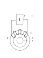
- FIG. 1 is a schematic configuration diagram illustrating a power supply device according to a first embodiment of the present disclosure. It is a schematic diagram which shows the magnetization characteristic of the core for power supplies. It is a figure which shows the waveform of the induced current produced with the coil for power supplies. It is a figure which shows the waveform of the induced current produced with the coil for power supplies. It is a schematic perspective view which shows the power line physical quantity measuring device which concerns on 2nd Embodiment of this indication. It is a block diagram showing a power line physical quantity measuring device concerning a 2nd embodiment of this indication. It is a front view showing a power line physical quantity measuring device concerning a 2nd embodiment of this indication.
- FIG. 6B is a sectional view taken along line AA in FIG. 6A. It is a rear view which shows the power line physical quantity measuring device which concerns on 2nd Embodiment of this indication. It is the BB sectional view taken on the line of FIG. 7A.
- It is a block diagram showing a communication apparatus concerning a 3rd embodiment of this indication. It is a schematic block diagram which shows the power line physical quantity measuring device which concerns on 4th Embodiment of this indication. It is a schematic block diagram which shows the communication system which concerns on 4th Embodiment of this indication.
- An object of the present disclosure is to provide a technique capable of obtaining stable power from a magnetic field generated around a power line.
- the current transformer attached to the power line has, for example, a core and a coil.
- a predetermined electric power can be obtained by generating an induced current in the coil by electromagnetic induction from the magnetic field generated in the core.
- the value of the current flowing through the power line varies in real time depending on the amount of power generation and the power demand.
- the power required for various devices attached to the power line does not depend on the value of current flowing through the power line. Therefore, a power supply device is desired in which the amount of power generation does not vary regardless of the value of the current flowing through the power line.
- the current transformer unit can obtain sufficient power in the load. And the power supply is designed.
- the current value of the current is the upper limit of the above fluctuation range.
- the current value of the current is the upper limit of the above fluctuation range.
- the current transformer is housed in, for example, a metal cylindrical main body.
- the main body includes, for example, an inner cylinder through which a power line is inserted, and an outer cylinder that houses a current transformer section between the inner cylinder and itself.
- the inventors have found that when the current transformer part is accommodated in a metal main body part, the power generation efficiency in the current transformer part may be lowered.
- a power supply device includes: A power supply core provided so as to surround a power line; and a power supply coil that is wound around the power supply core and generates an induced current by electromagnetic induction based on a change in magnetic flux generated in the power supply core by a current flowing through the power line.
- a power source current transformer having a coil;
- a power supply unit connected to the power supply current transformer unit and supplying power to a predetermined load based on the induced current generated in the power supply current transformer unit;
- the power supply core is configured to be magnetically saturated with respect to a magnetic field generated by the current flowing through the power line when a current value of the current flowing through the power line is a predetermined current value less than or equal to an allowable current value of the power line. Is done. According to this configuration, stable power can be obtained from the magnetic field generated around the power line.
- the current value of the power line when the magnetic field strength generated around the power line becomes a magnetic saturation point in the magnetization curve indicated by the power supply core is lower than the lower limit value of the fluctuation range of the peak value of the current flowing through the power line. Within ⁇ 10%. According to this configuration, the magnetic saturation of the power supply core can be obtained over substantially the entire fluctuation range of the peak value of the current of the power line.
- a main body for holding the current transformer for power supply and the power supply outside the power line is An inner cylinder through which the power line is inserted;
- An outer cylinder that is provided so as to surround the outer periphery of the inner cylinder, and that houses the power transformer and the power supply section between the inner cylinder and itself;
- the inner cylinder is separated into at least two in the axial direction. According to this configuration, it is possible to suppress a decrease in power generation efficiency due to the power supply CT unit.
- a power supply device includes: A power supply core provided so as to surround a power line; and a power supply coil that is wound around the power supply core and generates an induced current by electromagnetic induction based on a change in magnetic flux generated in the power supply core by a current flowing through the power line.
- a power source current transformer having a coil;
- a power supply unit connected to the power supply current transformer unit and supplying power based on the induced current generated in the power supply current transformer unit;
- a main body for holding the current transformer for power supply and the power supply on the outside of the power line;
- the body part is An inner cylinder through which the power line is inserted;
- An outer cylinder that is provided so as to surround the outer periphery of the inner cylinder, and that houses the power transformer and the power supply section between the inner cylinder and itself;
- Have The inner cylinder is separated into at least two in the axial direction. According to this configuration, it is possible to suppress a decrease in power generation efficiency due to the power supply CT unit.
- the power core has a pair of halved cores divided in the axial direction, At least one of the pair of half cores is An end that is mated to the other of the pair of half cores; A linear portion extending linearly toward the end; and Have According to this structure, a pair of half cores can be stably couple
- a current measuring core provided to surround the power line, and an induced voltage by electromagnetic induction based on a change in magnetic flux generated in the current measuring core by the current flowing in the power line wound around the current measuring core.
- a current measuring coil for generating a current measuring current transformer section A current measuring unit connected to the current measuring current transformer unit and measuring the current flowing through the power line based on the induced voltage output by the current measuring current transformer unit;
- the current measuring core is configured not to be magnetically saturated with respect to a magnetic field generated by the current flowing through the power line as long as a current value of the current flowing through the power line is equal to or less than an allowable current value of the power line. According to this configuration, the current measurement accuracy can be improved.
- a power line physical quantity measuring device includes: A power supply core provided so as to surround a power line; and a power supply coil that is wound around the power supply core and generates an induced current by electromagnetic induction based on a change in magnetic flux generated in the power supply core by a current flowing through the power line.
- a power source current transformer having a coil;
- a power supply unit connected to the power supply current transformer unit and supplying power based on the induced current generated in the power supply current transformer unit;
- a physical quantity measuring unit for measuring a physical quantity related to the power line by the power supplied from the power supply unit;
- the power supply core is configured to be magnetically saturated with respect to a magnetic field generated by the current flowing through the power line when a current value of the current flowing through the power line is a predetermined current value less than or equal to an allowable current value of the power line. Is done. According to this configuration, the power supply from the power supply CT unit to the physical quantity measurement unit can be stably maintained by the magnetic saturation of the power supply core.
- a communication device is provided.
- a power supply core provided so as to surround a power line; and a power supply coil that is wound around the power supply core and generates an induced current by electromagnetic induction based on a change in magnetic flux generated in the power supply core by a current flowing through the power line.
- a power source current transformer having a coil;
- a power supply unit connected to the power supply current transformer unit and supplying power based on the induced current generated in the power supply current transformer unit;
- a communication unit that communicates predetermined information with the power supplied from the power source unit;
- the power supply core is configured to be magnetically saturated with respect to a magnetic field generated by the current flowing through the power line when a current value of the current flowing through the power line is a predetermined current value less than or equal to an allowable current value of the power line. Is done. According to this configuration, the power supply from the power supply CT unit to the communication unit can be stably maintained by the magnetic saturation of the power supply core.
- FIG. 1 is a schematic configuration diagram illustrating a power supply device according to the present embodiment.
- the power supply device 10 of the present embodiment is configured to generate predetermined power using electromagnetic induction from the power line 100, and for example, a power supply current transformer unit (power supply CT unit) 420. And a power supply unit (power supply circuit unit) 440.
- a power supply current transformer unit power supply CT unit
- a power supply circuit unit power supply circuit unit
- the “power line 100” means a linear body that transmits power, and includes, for example, an overhead transmission line, an overhead transmission line, and a power cable. Contains.
- the power line 100 is configured as a so-called overhead power transmission line, for example.
- the power line 100 is, for example, a steel core aluminum stranded wire (ACSR).
- the power line 100 is configured, for example, as a conductor that is provided by twisting a plurality of strands so as to cover the center portion that bears the tension at the time of overhead wiring and the outer periphery of the center portion, and allows current to flow during power transmission.
- a stranded wire layer is an aluminum covered steel wire (AC wire), for example.
- the strand which comprises a twisted wire layer consists of aluminum (Al) or Al alloy, for example.
- the power supply CT unit 420 includes, for example, a power supply core 422 and a power supply coil 424.
- the power supply core 422 is provided in an annular shape so as to surround the outer periphery of the power line 100.
- the power core 422 is made of a magnetic material.
- the magnetic body constituting the power supply core 422 is, for example, ferrite.
- the power supply coil 424 is spirally wound around at least a part of the power supply core 422. With such a configuration, an induction current can be generated in the power supply coil 424 by electromagnetic induction based on a change in magnetic flux generated in the power supply core 422 around the power line 100 by a current flowing through the power line 100.
- the power supply unit 440 is connected to the power supply CT unit 420 and configured to supply power to a predetermined load (not shown) based on the induced current generated in the power supply CT unit 420.
- the power supply unit 440 includes, for example, a protection unit (not shown), a rectification unit (not shown), and a constant voltage circuit unit (waveform shaping unit) (not shown).
- the protection unit is configured to release the surge current so that the surge current does not flow to the load.
- the rectifying unit is configured to convert (rectify) AC power based on the induced current generated in the power supply CT unit 420 into DC power suitable for the load, for example.
- the constant voltage circuit unit has a function of adjusting, for example, the DC voltage generated by the rectifier unit to a constant voltage suitable for the load.
- FIG. 2 is a schematic diagram showing the magnetization characteristics of the power supply core.
- the power supply core 422 of the present embodiment has a current value of the current I 1 flowing through the power line 100 being a predetermined current value that is equal to or less than an allowable current value of the power line 100.
- it is configured to be magnetically saturated with respect to the magnetic field generated around the power line 100 by the current flowing through the power line 100. Thereby, generation
- magnetic saturation means that the magnetic flux density B is saturated with respect to the magnetic field strength H.
- the “allowable current value” here means the maximum value of the current I 1 that the power line 100 can flow (without being damaged).
- the “maximum magnetic field strength” in FIG. 2 means the maximum value of the magnetic field strength generated around the power line 100 when the current value of the power line 100 is an allowable current value.
- the magnetization characteristic (magnetization curve) of the power source core 422 has, for example, a monotonically increasing region MR1, a magnetic saturation point SP1, and a saturation region SR1.
- the monotonically increasing region MR1 is a region where the magnetic flux density B monotonously increases with respect to the magnetic field strength H, for example.
- the saturation region SR1 is a region where the magnetic flux density B is substantially constant with respect to the magnetic field strength H.
- the magnetic saturation point SP1 is a point at which the monotonically increasing region MR1 changes to the saturation region SR1 with respect to the magnetic field strength H.
- the magnetic saturation point SP1 is, for example, an inflection point of the gradient of the magnetic flux density B with respect to the magnetic field strength H.
- a magnetic saturation point SP1 is positioned below the maximum magnetic field strength H p. That is, when the current value of the current I 1 flowing through the power line 100 is a predetermined current value equal to or less than the allowable current value of the power line 100, the power source core 422 is magnetically saturated.
- the magnetic body has a specific maximum magnetic flux density.
- the magnetic flux density is saturated without becoming higher than the maximum magnetic flux density even if the magnetic field strength is greater than the magnetic saturation point.
- the magnetic saturation point depends on the material of the magnetic material, the cross-sectional area of the magnetic material, the number of coil turns, and the like.
- the power supply core 422 of the present embodiment is made of a magnetic material that is magnetically saturated when the current value of the current I 1 flowing through the power line 100 is a predetermined current value that is equal to or less than the allowable current value of the power line 100, for example.
- predetermined magnetic saturation can be realized by selecting a predetermined magnetic element constituting the magnetic body or adjusting the composition ratio of the magnetic elements.
- the power core 422 of the present embodiment for example, the allowable current value of the current power line 100 of the current I 1 flowing through the power line 100 It may have a cross-sectional area adjusted so as to be magnetically saturated at the following predetermined current value.
- the power supply core 422 of this embodiment has a pair of half cores divided, for example along the axial direction.
- the pair of half cores may be separated by a predetermined gap.
- the definition of “half-divided along the axial direction” will be described later.
- the gap between the pair of halved cores is such that, for example, when the current value of the current I 1 flowing through the power line 100 is a predetermined current value equal to or less than the allowable current value of the power line 100, the power core 422 is magnetically saturated. To be adjusted.
- the induced current I 2 generated in the power supply coil 424 is 0 (A).
- the waveform of the induced current I 2 is to deviate from the sine wave.
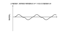
- FIGS. 3A and 3B are diagrams showing waveforms of the induced current I 2 generated in the power supply coil.
- FIGS. 3A and 3B shows the waveform of the induced current I 2 when connecting a predetermined linear resistance to the power supply coil 424.
- 3A and 3B when the current value of the current I 1 is a current value at which the magnetic field strength is near the magnetic saturation point SP1, and when the current value of the current I 1 is the saturation region SR1 when the current value becomes the inner, shows the waveform of the induced current I 2. Note that the current value of the current I 1 is less than the allowable current value.
- the power source core 422 is magnetically saturated, for example.
- the waveform of the induced current I 2 generated in the power supply coil 424 can be made a waveform lacking a part of the sine wave and deviated from the sine wave. .
- the integrated value obtained by integrating the current value of the induced current I 2 as the current value of the current I 1 becomes larger.
- the current value of the induction current I 2 can be reduced from the integrated value. In other words, even if there is an increase in the current I 1 flowing through the power line, it is possible to suppress the occurrence of unnecessary excessive power to the load.
- power core 422 is magnetically saturated, by variation of the magnetic flux ⁇ is zero in the formula (1) described above, the waveform of the induced current I 2, the induced current I 2 After the absolute value of the current value decreases from the peak value, there is a zero current region (ZT) in which the current value of the induced current I 2 is constant at approximately 0 A for a predetermined time. Since the waveform of the induction current I 2 has the zero current region (ZT), it is possible to ensure the time when a part of the sine wave is missing. As a result, generation of excessive power can be stably suppressed.
- the power supply unit 440 adapted to the load current Will be shaped into a waveform (constant current waveform).
- the power core 422 shows the induction current I 2 having a waveform shown in FIGS. 3A and 3B, for example, when a magnetic field intensity generated around the power line 100 in the magnetization curve showing the power core 422 is magnetic saturation point
- the current value of the current I 1 of the power line 100 is within ⁇ 10% with respect to the lower limit value of the fluctuation range of the peak value of the current I 1 flowing through the power line 100.
- the fluctuation range of the peak value of the current I 1 flowing through the power line 100 refers to the power line 100 due to fluctuations in the power supply status from the power plant, fluctuations in the power usage status on the load side, fluctuations in temperature, and the like. It means a range in which the peak value of the flowing current I 1 can vary.
- the current value of the current I 1 of the power line 100 when the magnetic field intensity becomes the magnetic saturation point in the magnetization curve showing the power core 422 with respect to the lower limit value of the fluctuation range of the peak value of the current I 1 By setting it within ⁇ 10%, the magnetic saturation of the power supply core 422 can be obtained over substantially the entire fluctuation range of the peak value of the current I 1 of the power line 100. That is, as soon as the current value of the current I 1 of the power line 100 becomes larger than the lower limit value of the fluctuation range, the power source core 422 can be magnetically saturated immediately.
- the power supply core 422 is configured to be magnetically saturated with respect to the magnetic field generated around the power line 100 when the current value of the current I 1 flowing through the power line 100 is a predetermined current value that is equal to or less than the allowable current value of the power line 100. Has been. As a result, as the current value of the current I 1 increases, the waveform of the induced current I 2 can be made a waveform lacking a part of the sine wave and deviated from the sine wave. By setting the waveform of the induced current I 2 to the above waveform, the integrated value obtained by integrating the current value of the induced current I 2 as the current value of the current I 1 becomes larger.
- the current value of the induction current I 2 can be reduced from the integrated value. Further, when the current value of the current I 1 becomes large, the rate of increase of the integrated value obtained by integrating the current value of the induced current I 2 is made smaller than the rate of increase of the integrated value obtained by integrating the current value of the current I 1. be able to. In other words, even if there is an increase in the current I 1 flowing through the power line 100, it is possible to suppress the occurrence of unnecessary excessive power to the load. As a result, stable power can be obtained.
- the power supply CT unit 420 By obtaining stable power from the power supply CT unit 420, it is possible to suppress excessive heat generation in the load or the wiring connected thereto. Thereby, it can suppress that a load or wiring etc. are damaged. As a result, the power supply by the power supply device 10 can be stably maintained, and the power supply device 10 can be operated semipermanently.
- the power supply device 10 in the first embodiment described above can be applied as the power line physical quantity measuring device 12, for example. It may be considered that the power line physical quantity measuring device 12 incorporates the power supply device 10 of the first embodiment described above and the communication device 14 of the third embodiment described later.
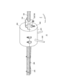
- FIG. 4 is a schematic perspective view showing the power line physical quantity measuring apparatus according to the present embodiment.
- FIG. 5 is a block diagram showing the power line physical quantity measuring apparatus according to the present embodiment.
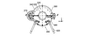
- FIG. 6A is a front view showing the power line physical quantity measuring device according to the present embodiment.
- FIG. 6B is a side view showing the power line physical quantity measuring device according to the present embodiment.
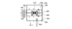
- 6C is a cross-sectional view taken along line AA of FIG. 6A.
- FIG. 7A is a rear view showing the power line physical quantity measuring device according to the present embodiment.
- FIG. 7B is a cross-sectional view taken along the line BB of FIG. 7A.
- FIG. 8 is a schematic diagram showing the magnetization characteristics of the power supply core and the magnetization characteristics of the current measurement core.
- FIG. 9 is a schematic view showing a current transformer for power supply.
- FIG. 10 is a schematic diagram showing a current transformer for current measurement.
- the “axial direction” of the power line 100 or the like refers to the direction along the central axis of the power line 100 or the like, and in some cases can be rephrased as the longitudinal direction of the power line 100 or the like.
- the “radial direction” of the power line 100 or the like refers to a direction perpendicular to the axial direction of the power line 100 or the like, and can be paraphrased as a short direction of the power line 100 or the like depending on circumstances.
- the “circumferential direction” of the power line 100 or the like means a direction along the outer periphery of the power line 100 or the like.
- the “X direction” means a direction that is perpendicular to the axial direction of the power line 100 and in the horizontal direction, and the direction from the central axis of the main body 300 toward the hinge part 370 is “+ X direction”.
- the “Y direction” means the axial direction and the horizontal direction of the power line 100, and the direction from the clamp 700 toward the main body 300 is defined as “+ Y direction”.
- the “Z direction” means the vertical direction, and the vertically upward direction is the “+ Z direction”.
- the power line physical quantity measuring device 12 of the present embodiment is attached to the power line 100, for example, measures a physical quantity related to the power line 100, and communicates information (hereinafter referred to as “physical quantity data”) related to the measured physical quantity of the power line 100. It is configured to Specifically, the power line physical quantity measuring device 12 includes, for example, a main body unit 300, a power source current transformer unit 420, a power source unit 440, a physical quantity measuring unit (current measuring current transformer unit 520, current measuring unit 540, and Temperature sensor unit 200), communication unit 600, and clamp 700.
- the clamp 700 is, for example, in the axial direction (Y direction) of the power line 100 on the outside of the main body 300, which will be described later, in the axial direction of the power line 100. Is connected to one end of the main body 300. The clamp 700 holds the power line 100 and fixes one end of the main body 300 to the power line 100.
- the clamp 700 includes, for example, a clamp lower part 720 and a clamp upper part 740.
- the lower clamp portion 720 is connected to, for example, a lower half portion 360 of a main body 300 described later by welding, and is disposed on the vertical lower side of the power line 100.
- the clamp lower part 720 has the recessed part (code
- the upper clamp portion 740 is configured as a separate body that can be separated from the lower clamp portion 720, for example, and is disposed on the vertical upper side of the power line 100.
- the clamp upper part 740 is comprised symmetrically with the clamp lower part 720, for example, and has the recessed part (code
- the lower clamp portion 720 and the upper clamp portion 740 are disposed to face each other with the power line 100 interposed therebetween, and are screwed to each other in a state where the power line 100 is fitted in the respective recesses. Accordingly, the power line 100 can be gripped by the clamp 700 and one end of the main body 300 can be fixed to the power line 100.
- the clamp 700 is made of, for example, the same metal as that constituting the stranded wire layer of the power line 100. Specifically, the clamp 700 is made of, for example, Al or an Al alloy. Thereby, it is possible to suppress the occurrence of electrolytic corrosion due to the contact between the clamp 700 and the power line 100.
- the clamp 700 holds the power line 100, a main body 300 described later is electrically connected to the power line 100 via the clamp 700. Thereby, the clamp 700 and the main body 300 are equipotential with the power line 100.
- the main body unit 300 is configured to hold members other than the temperature sensor unit 200 on the outside of the power line 100.
- the main body 300 is made of a metal that does not contain a magnetic material, for example.
- the main body 300 of the present embodiment is made of, for example, Al or an Al alloy. Thereby, it is possible to suppress shielding of the magnetic field around the power line 100 due to the main body 300.
- the main-body part 300 can be reduced in weight because the main-body part 300 consists of Al or Al alloy.
- the main body 300 of this embodiment has, for example, a double cylinder structure.
- the main body 300 includes, for example, an inner cylinder 320, an outer cylinder 340, and a lid 350.
- the power line 100 is inserted into the inner cylinder 320 at intervals in the radial direction.
- the outer cylinder 340 is provided so as to surround the outer periphery of the inner cylinder 320, and forms an accommodating portion 330 as an accommodating space between the inner cylinder 320 and itself.
- the lid part 350 connects the end part in the axial direction of the inner cylinder 320 and the end part in the axial direction of the outer cylinder 340 to block the accommodating part 330.
- a power supply CT unit 420, a power supply unit 440, a current measurement CT unit 520, a current measurement unit 540, and a communication unit 600 are stored in the storage unit 330.
- the main body 300 since the main body 300 has a double cylinder structure, the intrusion of rainwater into the housing portion 330 can be suppressed.
- the inner cylinder 320 is separated into at least two in the axial direction, for example.
- the inner cylinder 320 includes, for example, an annular insulating portion 322 that divides over the entire circumference of the inner cylinder 320 in a part in the axial direction of the inner cylinder 320.
- the inner cylinder 320 can be considered to be cut by a cross section that intersects (orthogonally) the axial direction, for example.
- one side and the other side of the inner cylinder 320 in the axial direction are separated via the insulating portion 322.
- an insulator is fitted in the insulating portion 322.
- an insulating resin is used as an insulator fitted in the insulating part 322, for example.
- the gaps other than the power supply CT unit 420, the power supply unit 440, the current measurement CT unit 520, the current measurement unit 540, and the communication unit 600 are filled with a filler (not shown).
- the filler is, for example, silicone rubber. Thereby, the waterproofness in the accommodating part 330 can be improved.
- At least the outer cylinder 340 has a cylindrical shape, for example. That is, there are few projecting parts in the outer shape of the main body 300 that is equipotential with the power line 100. Thereby, generation
- not only the shape of the outer cylinder 340 but also the shape of the inner cylinder 320 is, for example, a cylindrical shape.
- the housing portion 330 between the inner cylinder 320 and the outer cylinder 340 can be widened while reducing the size of the main body 300.
- one end of the inner cylinder 320 in the axial direction of the power line 100 is fixed to the power line 100 via the clamp 700 and is electrically connected to the power line 100. It is connected to the.
- the other end of the inner cylinder 320 in the axial direction of the power line 100 is insulated while being separated from the power line 100 in the radial direction. Thereby, it can suppress that both the one end and the other end of the main-body part 300 of the axial direction of the power line 100 are electrically connected to the power line 100.
- FIG. As a result, it is possible to suppress the formation of a bypass for the current flowing through the power line 100.
- the main body 300 of the present embodiment is, for example, divided in half (divided into two) along the axial direction.
- “half-divided along the axial direction” means being divided into two by a plane including the axis or a plane parallel to the axis.
- the “plane” here is not limited to one, but may be a combination of two or more planes.
- the “plane parallel to the axis” here is not limited to a plane completely parallel to the axis, and may be a plane inclined with respect to the axis with a predetermined error.
- the definition when the other members are “half-divided along the axial direction” is the same as the above-described definition.
- the main body 300 has, for example, a lower half 360, an upper half 380, and a hinge 370.
- the lower half portion 360 is configured as one of the main body portions 300 that are divided in half along the axial direction, and is disposed on the vertically lower side.
- the upper half portion 380 is configured as the other one of the main body portion 300 divided in the axial direction, and the lower half portion 360 on the opposite side (vertical upper side) to the lower half portion 360 across the power line 100. It arrange
- the hinge portion 370 is provided at each circumferential end of the lower half portion 360 and the upper half portion 380, and connects the lower half portion 360 and the upper half portion 380 so as to be openable.
- each of both ends in the circumferential direction of the lower half portion 360 and each of both ends in the circumferential direction of the upper half portion 380 are screwed together by, for example, a bolt (not shown) and a nut (not shown). ing. With such a configuration, the main body 300 can be easily attached to the existing power line 100.
- the power supply CT unit 420 and the power supply unit 440 of the present embodiment are configured in the same manner as in the first embodiment described above, for example.
- the power supply CT unit 420 includes, for example, a power supply core 422 and a power supply coil 424.
- the power source core 422 of the present embodiment is configured so that the power line 422 is, for example, when the current value of the current I 1 flowing through the power line 100 is a predetermined current value that is equal to or smaller than the allowable current value of the power line 100 It is configured to be magnetically saturated with respect to a magnetic field generated around the power line 100 by a current flowing through the power line 100.
- the power supply CT section 420 is provided in an annular shape so as to surround the power line 100 in the housing section 330 of the main body section 300, for example.
- the power supply CT unit 420 of the present embodiment is, for example, divided in half along the axial direction.
- the power supply CT unit 420 includes, for example, a power supply lower part 420d and a power supply upper part 420u.
- the power source lower part 420d is configured as one of the power source CT parts 420 divided in half along the axial direction, and is accommodated in the lower half part 360 of the main body part 300.
- the power supply upper part 420u is configured as, for example, the other of the power supply CT parts 420 divided in the axial direction, and is accommodated in the upper half part 380 of the main body part 300.
- the lower part 420d for power supply and the upper part 420u for power supply are arranged so that the shafts of the respective power supply cores 422 are arranged when the lower half part 360 and the upper half part 380 are closed (when they are connected to face each other). It arrange
- the power supply coil 424 of the present embodiment is provided, for example, spirally wound only on the power supply upper part 420u. Further, as shown in FIG. 6C, the power supply coil 424 and the power supply unit 440 are accommodated in, for example, the upper half 380 of the main body unit 300.
- the circuit board constituting the power supply unit 440 is provided in a semicircular arc shape following the shape of the upper half portion 380, for example. Since the power supply coil 424 and the power supply unit 440 are accommodated in the upper half 380 in this manner, the wiring connecting the power supply coil 424 and the power supply unit 440 can be shortened.
- the power source core 422 of the present embodiment has, for example, a pair of half cores 423 that are half divided along the axial direction.
- the power core 422 of the present embodiment is configured in a substantially elliptical shape, for example. That is, each of the pair of half cores 423 in the power supply core 422 has, for example, a pair of end portions 423e, an arc portion 423r, and a straight portion 423l. Each of the pair of end portions 423e is aligned with the other of the pair of half cores 423, for example, at both ends in the axial direction of the half core 423.
- the arc portion 423r is provided in an arc shape so as to surround the outer periphery of the power line 100 between the pair of end portions 423e.
- the straight portion 423l extends linearly from the arc portion 423r toward the end portion 423e.
- the pair of halved cores 423 in the power supply core 422 can be stably coupled to each other. As described above, a predetermined gap may be provided between the pair of halved cores 423 in order to obtain the magnetic saturation of the power supply core 422.
- the power source CT unit 420 includes, for example, a communication unit 600, a power source unit 440, and a later-described main unit 300 (in the axial direction of the power line 100). It is provided closer to the clamp 700 than the circuit board such as the current measuring unit 540.
- the power supply core 422 included in the power supply CT unit 420 is made of a magnetic material as described above, and is heavier than other members. For this reason, the torque applied to the main body 300 due to the gravity of the power supply core 422 can be reduced by bringing the power supply CT unit 420 closer to the clamp 700.
- the physical quantity measurement unit is configured to measure a physical quantity related to the power line 100 using, for example, power supplied from the power supply unit 440.
- the physical quantity related to the power line 100 is, for example, the current I 1 flowing through the power line 100, the temperature of the power line 100, the vibration of the power line 100, the slackness of the power line 100, and the like.
- the power line physical quantity measurement device 12 serves as the physical quantity measurement unit, for example, a current measurement CT unit 520 and a current measurement unit 540 that measure the current I 1 flowing through the power line 100, and a temperature at which the temperature of the power line 100 is measured. And a sensor unit 200.
- the current measurement CT unit 520 of the present embodiment is configured in substantially the same manner as the power supply CT unit 420 described above, and includes, for example, a current measurement core 522 and a current measurement core. Coil 524.
- the current measuring core 522 is provided in an annular shape so as to surround the outer periphery of the power line 100.
- the current measuring core 522 is made of a magnetic material.
- the magnetic body constituting the current measuring core 522 is, for example, ferrite.
- the current measuring coil 524 is spirally wound around at least a part of the current measuring core 522.
- an induced voltage V is generated in the current measuring coil 524 by electromagnetic induction based on a change in the magnetic flux ⁇ generated in the current measuring core 522 around the power line 100 by the current I 1 flowing through the power line 100. Can do.
- I 1 NV / (KR) (2)
- N the number of turns of the current measuring coil 524
- R is a resistance value ( ⁇ ) of a termination resistor described later
- K is a coupling coefficient.
- the change in the magnetic flux ⁇ generated in the current measuring core 522 is changed so that the current value of the current I 1 can be accurately measured.
- the current I 1 is well tracked.
- the current measurement core 522 of the present embodiment has, for example, the power line 100 in a range where the current value of the current I 1 flowing through the power line 100 is less than or equal to the allowable current value of the power line 100.
- the magnetic field is not saturated with respect to the magnetic field generated around the power line 100 by the current I 1 flowing through the power line 100. Thus, it is possible to improve the measurement accuracy of the current I 1 flowing through the power line 100.
- a magnetic saturation point SP2 is located higher than the maximum magnetic field strength H p. That is, if the current value of the current I 1 flowing through the power line 100 is less than the allowable current value of the power line 100, current measuring core 522 is not magnetically saturated, the magnetic flux density B generated in the current measurement core 522 is monotonously increasing region MR2 Inside. This makes it possible throughout the operation range for the peak value of the current I 1, changes the induced voltage V linearly with respect to the current I 1. As a result, it is possible to improve the measurement accuracy of the current I 1.
- FIG. 8 shows the case where the slope of the monotonically increasing region MR1 of the power supply core 422 and the slope of the monotonically increasing region MR2 of the current measuring core 522 coincide with each other.
- the slope of the region MR1 may be different from the slope of the monotonously increasing region MR2 of the current measuring core 522.
- the current measurement CT unit 520 of the present embodiment is divided in half along the axial direction, for example, in the same manner as the power supply CT unit 420.
- the current measurement CT unit 520 includes, for example, a current measurement lower part 520d and a current measurement upper part 520u.
- the current measuring coil 524 of this embodiment is spirally wound, for example, over both the current measuring lower part 520d and the current measuring upper part 520u.
- the current measuring core 522 of the present embodiment has, for example, a pair of halved cores 523 divided in the axial direction.
- the current measurement core 522 of the present embodiment is configured in a substantially elliptical shape, for example, similarly to the power supply core 422. That is, each of the pair of halved cores 523 in the current measuring core 522 has, for example, a pair of end portions 523e, an arc portion 523r, and a straight portion 523l.
- the straight part 523l extends linearly from the arc part 523r toward the end part 523e. Thereby, a pair of halved cores 523 among the current measuring cores 522 can be stably coupled.
- the heavier one of the power supply CT unit 420 and the current measurement CT unit 520 is provided on the side closer to the clamp 700 than the other (in the axial direction of the power line 100) of the main body unit 300.
- the current measurement CT unit 520 is heavier than the power supply CT unit 420, for example, and thus is provided on the side of the main body unit 300 closer to the clamp 700 than the power supply CT unit 420 (FIG. 6C). And FIG. 7B).
- the power supply CT unit 420 and the current measurement CT unit 520 are preferably disposed adjacent to each other, for example. That is, it is preferable that there is no unnecessary gap between the power supply CT unit 420 and the current measurement CT unit 520 other than for each coil. Thereby, the torque added to the main-body part 300 can be made small reliably.
- the current measurement unit 540 includes, for example, a termination resistor (not shown) connected to the current measurement CT unit 520, and the current measurement CT unit 520 is expressed by the above equation (2).
- a current I 1 flowing through the power line 100 is measured based on the output induced voltage V.
- information related to the current I 1 of the power line 100 measured by the current measuring unit 540 is referred to as “current data”.
- the current measuring unit 540 is housed in the lower half 360 of the main body 300 together with the communication unit 600 described below, for example.
- the temperature sensor unit 200 is configured to be in contact with the power line 100 and measure the temperature of the power line 100, for example.
- the temperature sensor unit 200 includes, for example, a thermocouple that outputs a voltage corresponding to the temperature.
- the temperature sensor unit 200 is connected to the communication unit 600 in the main body unit 300 via a lead wire 280, for example.
- the temperature sensor unit 200 and the lead wire 280 are fixed to the power line 100 along the power line 100 by, for example, a binding band (not shown).
- the temperature sensor unit 200 is provided, for example, on the opposite side of the clamp 700 with the main body unit 300 sandwiched in the axial direction (Y direction) of the power line 100. Accordingly, the temperature sensor unit 200 can be separated from the clamp 700 by at least the length of the main body unit 300. Thereby, the temperature of the power line 100 can be accurately measured.
- the communication unit 600 is configured to communicate predetermined information, for example.
- the communication unit 600 is configured to wirelessly transmit information related to the physical quantity of the power line 100 measured by the physical quantity measurement unit to the outside.
- the communication unit 600 is connected to the current measurement CT unit 520 via the current measurement unit 540, for example, and is based on the induced voltage V output from the current measurement CT unit 520.
- the current data of the power line 100 measured in this way is acquired.
- the communication part 600 is connected to the temperature sensor part 200, for example, and is comprised so that the temperature data of the power line 100 which the temperature sensor part 200 measured may be acquired.
- the communication unit 600 is connected to the power source CT unit 420 via, for example, the power source unit 440, and wirelessly transmits various data such as temperature data and current data using the power supplied from the power source unit 440. It is configured as follows.
- the communication unit 600 includes, for example, an MCU (Micro Controller Unit) (not shown).
- the MCU included in the communication unit 600 includes, for example, a processor that executes a predetermined program related to transmission / reception of various data, a memory that stores the program and various data, one or more timers that serve as a reference for the transmission cycle, And an I / O port connected to each member. All the parts constituting the MCU are incorporated in one integrated circuit.
- the communication unit 600 may include an external memory such as a FROM (Flash Read-Only Memory), for example, separately from the memory included in the MCU.
- a FROM Flash Read-Only Memory
- the communication unit 600 includes, for example, an antenna 620 and is configured to transmit and receive various data via the antenna 620.
- the frequency band for transmission and reception by the communication unit 600 is, for example, the 920 MHz band.
- a 2.4 GHz band is often used as a frequency band for transmission and reception by the communication unit.
- the transmission distance (although depending on the length of the antenna 620) can be increased by about 2.6 times compared to the conventional case.
- the 920 MHz band it is possible to improve the diffractive properties of radio waves with respect to obstacles.
- the communication unit 600 is configured to transmit various data by so-called multi-hop wireless communication (bucket relay method), for example.
- multi-hop wireless communication bucket relay method
- the plurality of power line physical quantity measuring devices 12 are predetermined along the axial direction of the power line 100 (in the Y direction). Arranged at intervals.
- the communication unit 600 of the predetermined power line physical quantity measuring device 12 first receives, for example, various data from the adjacent power line physical quantity measuring device 12 on the upstream side (upstream side).
- the various data of the power line physical quantity measuring device 12 on the preceding stage side and its own various data are aggregated.
- various types of data are aggregated in the communication unit 600 of the predetermined power line physical quantity measuring device 12, the power line on the downstream side (downstream side) adjacent to the opposite side of the power line physical quantity measuring device 12 on the front stage across the predetermined power line physical quantity measuring device 12
- Various aggregated data are transmitted to the physical quantity measuring device 12. Such aggregation and transmission of various data are sequentially repeated in each of the plurality of power line physical quantity measuring devices 12.
- the power line physical quantity measuring device 12 at the last stage transmits, for example, the aggregated various data to a data aggregation transmission apparatus (not shown).
- the data aggregation transmission device transmits various aggregated data wirelessly or by wire to an electric power company as a power supply source that supplies power to the power line 100.
- the electric power company controls the power transmission capacity to the power line 100 based on various data.
- the power required for the communication unit 600 included in each power line physical quantity measuring device 12 is reduced, and the transmission distance of the plurality of power line physical quantity measuring devices 12 as a whole is reduced. Can be long.
- the communication unit 600 is configured to repeatedly transmit various data at a predetermined cycle, for example.
- the cycle in which the communication unit 600 transmits various data is, for example, 3 minutes.
- the electric power company that supplies power to the power line 100 can grasp the temperature of the power line 100 and the current of the power line 100 in real time based on various data transmitted from the power line physical quantity measuring device 12.
- the transmission capacity to the power line 100 can be controlled based on the temperature of the power line 100 and the current of the power line 100 in real time.
- efficient power transmission to the power line 100 can be realized.
- the communication unit 600 is mounted on the same circuit board together with the above-described current measurement unit 540, for example, and is accommodated in the lower half portion 360 of the main body 300.
- the circuit boards constituting the current measuring unit 540 and the communication unit 600 are provided in a semicircular arc shape following the shape of the lower half portion 360, for example.
- the antenna 620 of the communication unit 600 is provided so as to protrude outward from the lower half portion 360 of the main body 300, for example.
- the communication unit 600 and the antenna 620 are provided in the lower half part 360, that is, in the vertical lower side of the main body unit 300, so that a ground reception target (for example, a leader possessed by a ground worker) is provided. Etc.) can be transmitted stably.
- the communication unit 600 includes a pair of antennas 620, for example.
- Each of the pair of antennas 620 is inclined with respect to the vertical direction, for example.
- the pair of antennas 620 are provided symmetrically (in a C shape) with the center of the main body 300 as viewed from the axial direction of the main body 300. Accordingly, the correlation between the pair of antennas 620 can be reduced, and the antenna 620 having the better radio wave condition can be selectively transmitted / received. That is, the diversity effect by the communication unit 600 can be improved.
- the power supply device 10 can be applied as the power line physical quantity measuring device 12.
- the power core 422 is magnetically saturated, so that a physical quantity measuring unit as a load It is possible to suppress the generation of excessive power that is not necessary for the communication unit 600 and the like. Thereby, it can suppress that excessive heat_generation
- FIG. As a result, the power supply from the power supply CT unit 420 can be stably maintained, and the power line physical quantity measuring device 12 can be operated semipermanently.
- the power supply coil 424 and the power supply unit 440 are accommodated in the upper half portion 380 of the main body unit 300. Thereby, the wiring which connects the coil 424 for power supplies and the power supply part 440 can be shortened. Specifically, the connection of the power supply coil 424 between the upper half part 380 and the lower half part 360 can be eliminated. Further, it is possible to suppress the wiring connecting the power supply coil 424 and the power supply unit 440 from straddling between the upper half part 380 and the lower half part 360. As a result, the structure of the power line physical quantity measuring device 12 can be simplified.
- Each of the pair of halved cores 423 in the power supply core 422 has a straight portion 423l extending linearly toward the end portion 423e.
- the linear portions 423l are aligned in parallel to each other so that each of the pair of half cores 423 in the power supply core 422 is aligned. Position shift of the central axis can be suppressed. As a result, the pair of half cores 423 in the power supply core 422 can be stably coupled.
- the current measuring core 522 also has the straight portion 523 l as in the power supply core 422, so that the same effect as that of the power supply core 422 can be obtained.
- the power supply device 10 in the first embodiment described above can be applied as the communication device 14, for example. It may be considered that the power supply device 10 of the first embodiment described above is incorporated in the communication device 14.
- FIG. 11 is a block diagram showing a communication apparatus according to this embodiment.
- the communication device 14 of the present embodiment is attached to the power line 100, for example, and configured to relay predetermined information by multi-hop wireless communication.
- the communication device 14 includes, for example, a main body unit 300, a current transformer for power supply 420, a power supply unit 440, a communication unit 600, and a clamp 700.
- the communication unit 600 is configured to wirelessly transmit and receive predetermined information using, for example, power supplied from the power supply unit 440.
- the communication device 14 can be configured in the same manner as the power line physical quantity measurement device 12 of the second embodiment described above except that the communication device 14 does not have a physical quantity measurement unit.
- the power supply device 10 can be applied as the communication device 14.
- the power source core 422 is magnetically saturated, so that the communication unit 600 as a load has The generation of excessive power that is not necessary can be suppressed. Thereby, it can suppress that excessive heat_generation
- FIG. As a result, the power supply from the power supply CT unit 420 can be stably maintained, and the communication device 14 can be operated semipermanently.
- the communication device 14 of the present embodiment is configured to relay predetermined information by multi-hop wireless communication.
- the said communication apparatus 14 is applicable to the above-mentioned power transmission equipment monitoring system. Specifically, it is not necessary to measure the physical quantity of the power line 100, and only the transmission of various data can be relayed by using the communication device 14 in a place where the radio wave condition is deteriorated.
- the case where the power line 100 to which the power supply device 10 is attached is configured as an overhead power transmission line, but the present disclosure is not limited to this case.
- the power line 100 to which the power supply device 10 is attached may be configured as a power cable (insulation-coated cable), for example.
- the power supply device 10 measures a physical quantity related to the power line 100 while acquiring power using electromagnetic induction from the power line 100 as a power cable, for example.
- the power line physical quantity measuring device 16 can be applied. It may be considered that the power supply device 10 and the communication device 14 are incorporated in the power line physical quantity measuring device 16.
- FIG. 12 is a schematic configuration diagram showing a power line physical quantity measuring device according to the present embodiment.
- the power line 100 is shown in a sectional view.
- the power line physical quantity measuring device 16 of this embodiment includes, for example, a power current transformer unit 420, a power source unit 440, and physical quantity measuring units (current measuring current transformer unit 520, current measuring unit 540). And a communication current transformer section 660 and a communication section 640.
- the power line 100 of this embodiment is configured as, for example, a so-called solid-insulated cable (CV cable: Cross-linked Polyethylene insulated cable, or XLPE cable).
- the power line 100 includes, for example, a conductor 110, an internal semiconductive layer (not shown), an insulating layer 130, an external semiconductive layer (not shown), and a shield from the center side toward the outer peripheral side. It has a layer (metal shielding layer, metal sheath) 150 and a sheath (insulating sheath) 160.
- the pair of power lines 100 are peeled off stepwise in the axial direction, for example, and are connected in the connection box 800 with the central axes of the conductors 110 matching each other.
- FIG. 12 shows a normal connection portion (NJ1 or NJ2) to be described later as an example.
- the connection box 800 of the normal connection portion the shielding layers 150 of the pair of power lines 100 are connected to each other.
- a conductive line 152 is connected to the shielding layer 150 of the pair of power lines 100.
- the conductive wire 152 is drawn to the outside of the connection box 800.
- the drawn conductive wire 152 is connected to the conductive wire 152 connected to the shielding layer 150 in the other connection box 800 of the normal connection portion, and is grounded.
- the power supply CT unit 420 includes, for example, a power supply core 422 and a power supply coil 424.
- the power supply core 422 is provided in an annular shape so as to surround the outer periphery of the power line 100 (the outer periphery of the sheath 160).
- the power coil 424 is spirally wound around at least a part of the power core 422. With such a configuration, an induction current is generated in the power supply coil 424 by electromagnetic induction based on a change in magnetic flux generated in the power supply core 422 around the power line 100 by the conductor current (main current) flowing through the conductor 110 of the power line 100. Can be made.
- the power source core 422 of the present embodiment has a conductor current that flows through the power line 100 when the current value of the conductor current that flows through the conductor 110 of the power line 100 is a predetermined current value that is equal to or less than the allowable current value of the power line 100.
- the magnetic saturation point in the magnetization curve indicated by the power supply core 422 is, for example, positioned below the maximum value of the magnetic field strength generated around the power line 100 when the current value of the conductor current of the power line 100 is an allowable current value. are doing.
- the power supply core 422 exhibits magnetic saturation, generation of excessive power can be suppressed.
- the power supply unit 440 is connected to the power supply CT unit 420 and configured to supply power to the physical quantity measurement unit and the communication unit 640 based on the induced current generated in the power supply CT unit 420. .
- the power line physical quantity measurement device 16 includes, for example, a current measurement CT unit 520 and a current measurement unit 540 as physical quantity measurement units.
- the current measurement CT unit 520 of the present embodiment includes, for example, a current measurement core 522 and a current measurement coil 524.
- the current measuring core 522 is provided in an annular shape so as to surround the outer periphery of the power line 100.
- the current measuring coil 524 is spirally wound around at least a part of the current measuring core 522.
- the current measurement CT unit 520 is attached to the power line 100, so that a current (conductor current) flowing through the power line 100 is used for current measurement around the power line 100.
- An induced voltage can be generated in the current measuring coil 524 by electromagnetic induction based on a change in magnetic flux generated in the core 522. By measuring the induced voltage generated in the current measuring coil 524, the current flowing through the power line 100 can be obtained.
- the current measuring core 522 of the present embodiment for example, around the power line 100 by the current flowing in the power line 100 in a range where the current value of the current flowing in the power line 100 is equal to or less than the allowable current value of the power line 100. It is configured not to be magnetically saturated with respect to the generated magnetic field. Thereby, the measurement accuracy of the current flowing through the power line 100 can be improved.
- the current measurement unit 540 is connected to the current measurement CT unit 520 and configured to measure the current flowing through the power line 100 based on the induced voltage output from the current measurement CT unit 520.
- current data the information related to the current of the power line 100 measured by the current measuring unit 540 is referred to as “current data” as in the second embodiment.
- the power line physical quantity measuring device 16 of the present embodiment is configured to communicate predetermined information via the shielding layer 150 by, for example, inductive coupling with the shielding layer 150 of the power line 100. That is, the communication by the power line physical quantity measuring device 16 is a so-called power line communication (PLC: Power Line Communication).
- PLC Power Line Communication
- the communication unit 640 is configured to communicate information related to the physical quantity of the power line 100 measured by the physical quantity measurement unit, for example.
- the communication unit 640 is connected to the current measurement CT unit 520 via the current measurement unit 540, and acquires current data measured based on the induced voltage output from the current measurement CT unit 520. It is configured to The communication unit 640 is connected to the power supply CT unit 420 via, for example, the power supply unit 440, and is configured to communicate physical quantity data such as current data with power supplied from the power supply unit 440.
- the communication CT unit 660 is attached to the conductive wire 152 connected to the shielding layer 150, for example.
- the communication CT unit 660 is, for example, inductively coupled to the shielding layer 150 via the conductive wire 152. Accordingly, the communication unit 640 can communicate predetermined information with another communication device or another power line physical quantity measurement device via the shielding layer 150 by the communication CT unit 660.
- the communication CT unit 660 includes, for example, a communication core 662 and a communication coil 664.
- the communication core 662 is provided in an annular shape so as to surround the conductive wire 152 connected to the shielding layer 150, for example.
- the communication coil 664 is spirally wound around at least a part of the communication core 662.
- the communication unit 640 transmits predetermined information to another communication device or another power line physical quantity measurement device via the shielding layer 150 by the communication CT unit 660, and also by the communication CT unit 660. It is configured to receive predetermined information from another communication device or another power line physical quantity measuring device via the shielding layer 150.
- the operations of the communication CT unit 660 and the communication unit 640 are different between the case where the communication unit 640 transmits information and the case where the communication unit 640 receives information.
- the communication unit 640 When the communication unit 640 transmits information, for example, the communication unit 640 causes a predetermined transmission current to flow through the communication coil 664 and causes the communication core 662 to change magnetic flux by the transmission current. As a result, a signal current related to predetermined information is generated in the conductive wire 152 by electromagnetic induction as an induced current. As a result, the communication unit 640 can transmit a signal current related to predetermined information to another communication device or another power line physical quantity measurement device via the shielding layer 150.
- the change in magnetic flux generated in the communication core 662 follows the fluctuation of the transmission current well so that the signal current related to the predetermined information can be accurately generated from the transmission current. .
- the communication core 662 has a magnetic field against a magnetic field generated by the transmission current flowing in the communication coil 664 within a range necessary for performing communication related to predetermined information. It is configured not to saturate. Thus, the communication core 662 exhibits magnetic non-saturation in transmission, so that a signal current can be accurately generated from the transmission current.
- the communication unit 640 when the communication unit 640 receives information, a change in magnetic flux occurs in the communication core 662 due to a signal current transmitted from another communication device or another power line physical quantity measuring device and flowing through the conductive line 152.
- the communication coil 664 generates a reception current as an induced current by electromagnetic induction based on a change in magnetic flux generated in the communication core 662 by the signal current described above.
- the communication unit 640 can acquire predetermined information by demodulating the reception current generated in the communication coil 664.
- the change in magnetic flux generated in the communication core 662 follows the fluctuation of the signal current satisfactorily so that the reception current related to the predetermined information can be accurately generated from the signal current. .
- the communication core 662 is magnetically saturated with respect to a magnetic field generated by the signal current flowing through the conductive line 152 within a range necessary for performing communication related to predetermined information, for example, the signal current value. It is configured not to. As described above, the communication core 662 exhibits magnetic non-saturation in reception, so that a reception current can be accurately generated from a signal current.
- the communication core 662 has, for example, magnetic non-saturation in the above-described transmission. It is only necessary to be configured to show both the magnetic non-saturation in the above-described reception.
- the power line physical quantity measuring device 16 of the present embodiment can be applied to, for example, the communication system 20 used in the power system.
- FIG. 13 is a schematic configuration diagram showing a communication system according to the present embodiment. In FIG. 13, only the shielding layer 150 of the power line 100 is shown.
- the power system of the present embodiment is configured by, for example, a three-phase three-wire system.
- Three power lines 100 included in the power system are referred to as power lines a, b, and c. At least a part of the power system is laid in the ground, for example.
- the shielding layers 150 of the three power lines a to c are so-called cross-bonded. That is, the power system includes, for example, the normal connection portion NJ1, the insulation connection portion IJ1, the insulation connection portion IJ2, and the normal connection portion NJ2 in this order with a predetermined interval in the installation direction of the power line 100.
- power lines 100 connected as power line a are power lines a1 to a5
- power lines 100 connected as power lines b are power lines b1 to b5
- power lines 100 connected as power lines c are power lines c1 to c5.
- the shielding layers 150 are connected to each other in the pair of power lines 100 where the conductors 110 are connected to each other. Further, the shielding layers 150 of the power lines a to c are connected to each other and grounded via the conductive line 152.
- the one shielding layer 150 and the other shielding layer 150 are different from each other in the power line 100 of another phase. Is connected to the shielding layer 150 via a conductive wire 154.
- the shielding layer 150 of the power line a2 is connected to the shielding layer 150 of the power line b3 via the conductive line 154.
- the shielding layer 150 of the power line a3 is connected to the shielding layer 150 of the power line c2 via the conductive line 154.
- a series of sections constituted by the normal connection portion NJ1, the insulation connection portion IJ1, the insulation connection portion IJ2, and the normal connection portion NJ2 is referred to as a “cross bond interval CB”.
- the shielding layers 150 of the power lines a to c are connected in series to synthesize and cancel three sheath currents (inductive currents flowing through the shielding layer 150) having different phases. Can do.
- the above-mentioned cross bond section CB is repeatedly provided, for example, in the direction in which the power line 100 is laid.
- the communication system 20 of the present embodiment is used, for example, in a power system in which the shielding layers 150 of the above-described power lines a to c are cross-bonded.
- the communication system 20 includes, for example, a plurality of power line physical quantity measuring devices 16.
- Each of the plurality of power line physical quantity measuring devices 16 is configured to be able to communicate information related to the physical quantity of the power line 100 through the shielding layer 150 by inductive coupling with the shielding layer 150, for example.
- each of the plurality of power line physical quantity measurement devices 16 includes, for example, a power supply CT unit 420, a power supply unit 440, and a physical quantity measurement unit (current measurement CT) as described above.
- the power supply core 422 included in the power supply CT unit 420 exhibits the above-described magnetic saturation.
- the current measurement core 522 included in the current measurement CT unit 520 and the communication core 662 included in the communication CT unit 660 each exhibit the above-described magnetic non-saturation property.
- two power line physical quantity measuring devices 16 are provided in one cross bond section CB.
- the power line physical quantity measuring device 16a which is one of the two power line physical quantity measuring devices 16, is disposed, for example, in the normal connection portion NJ1
- the power line physical quantity measuring device 16b which is the other, is disposed, for example, in the normal connection portion NJ2. Yes.
- the power source CT unit 420 and the current measurement CT unit 520 are attached to the power line c1, for example.
- the communication CT unit 660 is attached to, for example, the conductive line 152 that connects the shielding layer 150 of the power line c1 and the shielding layer 150 of the power line c2.
- the power source CT unit 420 and the current measurement CT unit 520 are attached to the power line c4, for example.
- the communication CT unit 660 is attached to, for example, the conductive line 152 that connects the shielding layer 150 of the power line c4 and the shielding layer 150 of the power line c5.
- the communication by the two power line physical quantity measuring devices 16 in the present embodiment is performed as follows, for example.
- the communication unit 640 uses the communication CT unit 660 to transmit a signal current related to the physical quantity data. Is transmitted to the power line physical quantity measuring device 16b through the shielding layer 150.
- the communication unit 640 of the transmission source power line physical quantity measurement device 16a transmits the signal current related to the ID information of the transmission destination power line physical quantity measurement device 16b to the power line physical quantity measurement device 16b together with the signal current related to the physical quantity data.
- the communication unit 640 of the power line physical quantity measuring device 16a modulates the transmission current according to, for example, an orthogonal frequency division multiplexing (OFDM), so that a predetermined signal current is generated by the communication CT unit 660. Is generated. As a result, even when the signal-to-noise ratio is close to 0 dB, the signal current can be transmitted satisfactorily.
- OFDM orthogonal frequency division multiplexing
- the signal current transmitted from the communication CT unit 660 by the communication unit 640 of the power line physical quantity measuring device 16a is, for example, from the conductive line 152 to the shielding layer 150 of the power line c2, the conductive line 154, the shielding layer 150 of the power line a3, and the conductive line 154. , And through the shielding layer 150 of the power line b4, flows to the conductive line 152 to which the communication CT unit 660 of the power line physical quantity measuring device 16a is attached.
- a reception current is generated as an induced current in the communication coil 664 of the communication CT unit 660 by the signal current flowing through the conductive line 152.
- the communication unit 640 demodulates the reception current generated by the communication coil 664.
- the communication unit 640 confirms the ID information included in the information obtained by demodulating the reception current. If the ID information indicates the power line physical quantity measuring device 16b when the ID information is confirmed, the communication unit 640 acquires predetermined information from the received current.
- communication other than communication from the power line physical quantity measuring device 16a to the power line physical quantity measuring device 16b can be performed in the same manner as described above except that the communication path is different.
- communication from the power line physical quantity measuring device 16b to the power line physical quantity measuring device 16a can be performed. Thereby, communication concerning predetermined information can be reciprocated within the cross bond section CB.
- communication can be performed from the power line physical quantity measuring device 16b toward the power line physical quantity measuring device or the communication device in the adjacent cross bond section.
- multihop communication via the shielding layer 150 can be performed over a plurality of cross bond sections.
- the power supply device 10 can be applied as the power line physical quantity measuring device 16 that measures the physical quantity related to the power line 100 while acquiring power using electromagnetic induction from the power line 100 as a power cable.
- the power core 422 is magnetically saturated, thereby measuring the physical quantity as a load.
- Generation of excessive power that is not necessary for the communication unit or the communication unit 640 can be suppressed. Thereby, it can suppress that excessive heat_generation
- the power line physical quantity measuring device 16 is stably operated, so that confirmation work by an operator who manages the communication system 20 can be reduced and maintenance can be easily performed.
- the power line physical quantity measuring device 16 is configured to communicate predetermined information via the shielding layer 150 by inductive coupling with the shielding layer 150 of the power line 100. Thereby, for example, even if the power line 100 is laid in an environment where wireless communication is difficult, good communication can be performed through the shielding layer 150.
- the communication core 662 causes the transmission current flowing in the communication coil 664 to be within a range necessary for performing communication related to predetermined information. It is constituted so as not to be magnetically saturated with respect to the magnetic field generated by. Thereby, even if the transmission current fluctuates within a predetermined required range, the signal current can be linearly changed with respect to the transmission current. As a result, a signal current can be accurately generated from the transmission current.
- the communication core 662 uses the signal current flowing through the conductive wire 152 within a range in which the current value of the signal current is necessary for performing communication related to the predetermined information. It is configured not to be magnetically saturated with respect to the generated magnetic field. Thereby, even if the signal current fluctuates within a predetermined required range, the reception current can be linearly changed with respect to the signal current. As a result, a reception current can be generated accurately from the signal current.
- the power supply device 10 is applied as the power line physical quantity measuring device 12 or the communication device 14 has been described.
- the power supply device 10 is a device that obtains power from the power line 100
- the power line Devices other than the physical quantity measuring device 12 and the communication device 14 may be used.
- the power line physical quantity measurement device 12 uses, as the physical quantity measurement unit, for example, the current measurement CT unit 520 and the current measurement unit 540 that measure the current I 1 flowing through the power line 100, and the temperature of the power line 100.
- the power line physical quantity measurement device 12 may not include any one of the current measurement CT unit 520, the current measurement unit 540, and the temperature sensor unit 200.
- the power line physical quantity measuring device 12 may include other physical quantity measuring units other than the current measuring CT unit 520, the current measuring unit 540, and the temperature sensor unit 200.
- Examples of other physical quantity measuring devices include a vibration sensor, GPS (Global Positioning System), and the like.
- the vibration of the power line 100 can be measured by the vibration sensor.
- the vibration of the power line 100, the slackness of the power line 100, etc. can be measured by GPS.
- the temperature sensor unit 200 includes a thermocouple
- the present disclosure is not limited to this case.
- the temperature sensor unit 200 may include a thermistor whose resistance changes according to the temperature.
- the clamp 700 may have a C-shaped cross section.
- the present disclosure is not limited to this case.
- the main body 300 and the clamp 700 may be connected to each other so as to be separable from each other.
- the clamp 700 can be replaced according to the diameter of the power line 100.
- the power line physical quantity measuring device 12 power supply device 10
- the main body 300 has a double cylinder structure, but the present disclosure is not limited to this case.
- the main body 300 may not have a double cylinder structure.
- the main body 300 may have a single cylinder structure having only the outer cylinder 340.
- the main body 300 has the hinge 370
- the main body 300 may not have the hinge portion 370.
- the current measurement CT unit 520 is heavier than the power supply CT unit 420, and the current measurement CT unit 520 is provided closer to the clamp 700 than the power supply CT unit 420 in the main body unit 300.
- the present disclosure is not limited to this case.
- the power supply CT unit 420 is heavier than the current measurement CT unit 520, the power supply CT unit 420 is provided closer to the clamp 700 than the current measurement CT unit 520 in the main body 300. Also good.
- the communication unit 600 may include a general-purpose computer having a CPU (Central Processing Unit), a RAM (Random Access Memory), and a storage device.
- a CPU Central Processing Unit
- RAM Random Access Memory
- the communication unit 600 is configured to transmit various data by multi-hop wireless communication has been described, but the present disclosure is not limited to this case.
- the communication unit 600 may be configured to directly transmit various data to the data aggregation transmission device or the electric utility.
- the power line 100 is configured as a solid insulated cable.
- the power line 100 is configured as an OF cable (Oil Filled Cable) as long as it has a shielding layer. Also good.
- the power supply device 10 power line physical quantity measuring device 16
- the power supply apparatus 10 may be applied to an electric power system in which at least a part is laid on the ground, underwater or on the bottom of the water.
- the power supply core 422 is provided so as to surround the outer periphery of the sheath 160 of the power line 100 has been described.
- the power supply core 422 is connected by the power line 100 being peeled off in stages.
- the junction box 800 may be provided so as to surround the conductor 110.
- the power line physical quantity measurement device 16 includes, for example, the current measurement CT unit 520 and the current measurement unit 540 that measure the current flowing through the power line 100 as the physical quantity measurement unit has been described.
- the power line physical quantity measuring device 16 may include other physical quantity measuring units other than the current measuring CT unit 520 and the current measuring unit 540. Examples of other physical quantity measuring devices include a temperature sensor unit that measures the temperature of the power line 100.
- the power line physical quantity measuring device 16 is arranged in the normal connection portion NJ1
- the power line physical quantity measuring device 16 may be arranged in the insulating connection portion IJ1 or IJ2.
- the communication unit 600 of the power line physical quantity measurement device 16 is configured to perform both transmission and reception of predetermined information.
- predetermined information may be transmitted.
- the communication core 662 only needs to show magnetic non-saturation in transmission.
- the power supply device 10 is applied as the power line physical quantity measurement device 16 .
- the power supply device 10 is a device that obtains power from the power line 100 as a power cable
- the physical quantity measurement unit is provided. It may be a communication device that does not have.
- the communication device may be configured to relay predetermined information by multi-hop communication via the shielding layer 150, for example.
- the power line physical quantity measuring device 16 performs communication via the shielding layer 150 using the PLC.
- the power line physical quantity measuring device 16 is configured in an environment where a predetermined radio wave reaches the transmission destination. If there is, it may be configured to perform wireless communication.
- a power supply core provided so as to surround a power line; and a power supply coil that is wound around the power supply core and generates an induced current by electromagnetic induction based on a change in magnetic flux generated in the power supply core by a current flowing through the power line.
- a power source current transformer having a coil;
- a power supply unit connected to the power supply current transformer unit and supplying power to a predetermined load based on the induced current generated in the power supply current transformer unit;
- the power supply core is configured to be magnetically saturated with respect to a magnetic field generated by the current flowing through the power line when a current value of the current flowing through the power line is a predetermined current value less than or equal to an allowable current value of the power line. Power supply.
- the magnetic saturation point in the magnetization curve indicated by the power supply core is located at or below the maximum value of the magnetic field strength generated around the power line when the current value of the power line is an allowable current value.
- the integrated value obtained by integrating the current values of the induced current is the current value of the induced current when the power core is not magnetically saturated and the induced current is obtained as a sine wave as the current value of the current increases. 4.
- Appendix 8 A main body for holding the current transformer for power supply and the power supply outside the power line, The body part is An inner cylinder through which the power line is inserted; An outer cylinder that is provided so as to surround the outer periphery of the inner cylinder, and that houses the power transformer and the power supply section between the inner cylinder and itself; Have The power supply device according to any one of appendices 1 to 7, wherein the inner cylinder is separated into at least two in the axial direction.
- a power supply core provided so as to surround a power line; and a power supply coil that is wound around the power supply core and generates an induced current by electromagnetic induction based on a change in magnetic flux generated in the power supply core by a current flowing through the power line.
- a power source current transformer having a coil;
- a power supply unit connected to the power supply current transformer unit and supplying power based on the induced current generated in the power supply current transformer unit;
- a main body for holding the current transformer for power supply and the power supply on the outside of the power line; With The body part is An inner cylinder through which the power line is inserted;
- An outer cylinder that is provided so as to surround the outer periphery of the inner cylinder, and that houses the power transformer and the power supply section between the inner cylinder and itself;
- Have The power source device in which the inner cylinder is separated into at least two in the axial direction.
- the power core has a pair of halved cores divided in the axial direction, At least one of the pair of half cores is An end that is mated to the other of the pair of half cores; A linear portion extending linearly toward the end; and
- the power supply device according to any one of Supplementary Note 1 to Supplementary Note 10, which has:
- a current measuring core provided to surround the power line, and an induced voltage by electromagnetic induction based on a change in magnetic flux generated in the current measuring core by the current flowing in the power line wound around the current measuring core.
- a current measuring coil for generating a current measuring current transformer section A current measuring unit connected to the current measuring current transformer unit and measuring the current flowing through the power line based on the induced voltage output by the current measuring current transformer unit;
- the current measuring core is configured not to be magnetically saturated with respect to a magnetic field generated by the current flowing through the power line within a range where a current value of the current flowing through the power line is equal to or less than an allowable current value of the power line.
- the power supply device according to any one of 1 to appendix 11.
- the magnetic saturation point in the magnetization curve indicated by the current measuring core is located at a position higher than the maximum value of the magnetic field strength generated around the power line when the current value of the power line is an allowable current value.
- Appendix 14 The power supply device according to any one of appendix 1 to appendix 13, further including a communication unit that communicates predetermined information using the power supplied from the power supply unit.
- Appendix 15 A communication current transformer section inductively coupled with the power line shielding layer; 15. The power supply device according to appendix 14, wherein the communication unit communicates the information via the shielding layer by the communication current transformer unit.
- the communication current transformer unit is: A communication core provided so as to surround a conductive wire connected to the shielding layer; A communication coil wound around the communication core; Have The communication unit causes a transmission current to flow through the communication coil, causes a change in magnetic flux to the communication core by the transmission current, and causes a signal current related to the information to be generated in the conductive line by electromagnetic induction as an induced current. Configured and The communication core is configured not to be magnetically saturated with respect to a magnetic field generated by the transmission current flowing through the communication coil, as long as the current value of the transmission current is within a range necessary for performing communication related to the information.
- the power supply device according to appendix 15.
- the communication current transformer unit is: A communication core provided so as to surround a conductive wire connected to the shielding layer; A communication coil that is wound around the communication core and generates a reception current as an induced current by electromagnetic induction based on a change in magnetic flux generated in the communication core by a signal current related to the information flowing in the conductive wire; Have The communication unit is configured to demodulate the reception current generated in the communication current transformer unit to acquire the information,
- the communication core is configured not to be magnetically saturated with respect to a magnetic field generated by the signal current flowing through the conductive line, as long as a current value of the signal current is within a range necessary for performing communication related to the information.
- the power supply device according to 15 or 16.
- a power supply core provided so as to surround a power line; and a power supply coil that is wound around the power supply core and generates an induced current by electromagnetic induction based on a change in magnetic flux generated in the power supply core by a current flowing through the power line.
- a power source current transformer having a coil;
- a power supply unit connected to the power supply current transformer unit and supplying power based on the induced current generated in the power supply current transformer unit;
- a physical quantity measuring unit for measuring a physical quantity related to the power line by the power supplied from the power supply unit;
- the power supply core is configured to be magnetically saturated with respect to a magnetic field generated by the current flowing through the power line when a current value of the current flowing through the power line is a predetermined current value less than or equal to an allowable current value of the power line. Power line physical quantity measuring device.
- An inductive current is generated by electromagnetic induction on the basis of a change in magnetic flux generated in the power supply core that is wound around the power supply core and that is wound around the power supply core.
- a power supply current transformer having a power supply coil;
- a power supply unit connected to the power supply current transformer unit and supplying power based on the induced current generated in the power supply current transformer unit;
- a communication unit that communicates predetermined information with the power supplied from the power source unit;
- the power supply core is configured to be magnetically saturated with respect to a magnetic field generated by the current flowing through the power line when a current value of the current flowing through the power line is a predetermined current value less than or equal to an allowable current value of the power line.
- a power supply current transformer section having a power supply coil, A power supply unit connected to the power supply current transformer unit and supplying power based on the induced current generated in the power supply current transformer unit; A current transformer for communication inductively coupled with the shielding layer; A communication unit that communicates the information via the shielding layer by the communication current transformer unit, using the power supplied from the power source unit, With
- the power supply core is configured to be magnetically saturated with respect to a magnetic field generated by the current flowing through the power line when a current value of the current flowing through the power line is a predetermined current value less than or equal to an allowable current value of the power line.
Landscapes
- Engineering & Computer Science (AREA)
- Physics & Mathematics (AREA)
- General Physics & Mathematics (AREA)
- Theoretical Computer Science (AREA)
- Power Engineering (AREA)
- General Engineering & Computer Science (AREA)
- Measuring Instrument Details And Bridges, And Automatic Balancing Devices (AREA)
Abstract
電力線(100)を囲むように設けられる電源用コア(422)と、電源用コアに巻回され、電力線に流れる電流(I1)によって電源用コアに生じる磁束の変化に基づいて、電磁誘導により誘導電流(I2)を生じさせる電源用コイル(424)と、を有する電源用カレントトランス部(420)と、電源用カレントトランス部に接続され、電源用カレントトランス部で発生した誘導電流に基づいて、所定の負荷に対して電力を供給する電源部(440)と、を備え、電源用コアは、電力線に流れる電流の電流値が電力線の許容電流値以下の所定の電流値であるときに、電力線に流れる電流によって生じる磁界に対して磁気飽和するよう構成される。
Description
本開示は、電源装置、電力線物理量測定装置および通信装置に関する。
本出願は、2018年6月11日出願の日本国出願「特願2018-111010」に基づく優先権を主張し、前記日本出願に記載された全ての記載内容を援用するものである。
本出願は、2018年6月11日出願の日本国出願「特願2018-111010」に基づく優先権を主張し、前記日本出願に記載された全ての記載内容を援用するものである。
電力線に装着され処理を実行する各種装置において必要な電力を得るため、電力線の周囲に生じる磁界から、電磁誘導により誘導電流を生じさせるカレントトランス部が設けられることがある(例えば、特許文献1)。
本開示の一態様によれば、
電力線を囲むように設けられる電源用コアと、前記電源用コアに巻回され、前記電力線に流れる電流によって前記電源用コアに生じる磁束の変化に基づいて、電磁誘導により誘導電流を生じさせる電源用コイルと、を有する電源用カレントトランス部と、
前記電源用カレントトランス部に接続され、前記電源用カレントトランス部で発生した前記誘導電流に基づいて、所定の負荷に対して電力を供給する電源部と、
を備え、
前記電源用コアは、前記電力線に流れる前記電流の電流値が前記電力線の許容電流値以下の所定の電流値であるときに、前記電力線に流れる前記電流によって生じる磁界に対して磁気飽和するよう構成される
電源装置が提供される。
電力線を囲むように設けられる電源用コアと、前記電源用コアに巻回され、前記電力線に流れる電流によって前記電源用コアに生じる磁束の変化に基づいて、電磁誘導により誘導電流を生じさせる電源用コイルと、を有する電源用カレントトランス部と、
前記電源用カレントトランス部に接続され、前記電源用カレントトランス部で発生した前記誘導電流に基づいて、所定の負荷に対して電力を供給する電源部と、
を備え、
前記電源用コアは、前記電力線に流れる前記電流の電流値が前記電力線の許容電流値以下の所定の電流値であるときに、前記電力線に流れる前記電流によって生じる磁界に対して磁気飽和するよう構成される
電源装置が提供される。
本開示の他の態様によれば、
電力線を囲むように設けられる電源用コアと、前記電源用コアに巻回され、前記電力線に流れる電流によって前記電源用コアに生じる磁束の変化に基づいて、電磁誘導により誘導電流を生じさせる電源用コイルと、を有する電源用カレントトランス部と、
前記電源用カレントトランス部に接続され、前記電源用カレントトランス部で発生した前記誘導電流に基づいて電力を供給する電源部と、
前記電力線の外側に前記電源用カレントトランス部および前記電源部を保持する本体部と、
を備え、
前記本体部は、
内側に前記電力線が挿通される内筒と、
前記内筒の外周を囲むように設けられ、前記内筒と自身との間に前記電源用カレントトランス部および前記電源部を収容する外筒と、
を有し、
前記内筒は、軸方向に少なくとも2つに分離されている
電源装置が提供される。
電力線を囲むように設けられる電源用コアと、前記電源用コアに巻回され、前記電力線に流れる電流によって前記電源用コアに生じる磁束の変化に基づいて、電磁誘導により誘導電流を生じさせる電源用コイルと、を有する電源用カレントトランス部と、
前記電源用カレントトランス部に接続され、前記電源用カレントトランス部で発生した前記誘導電流に基づいて電力を供給する電源部と、
前記電力線の外側に前記電源用カレントトランス部および前記電源部を保持する本体部と、
を備え、
前記本体部は、
内側に前記電力線が挿通される内筒と、
前記内筒の外周を囲むように設けられ、前記内筒と自身との間に前記電源用カレントトランス部および前記電源部を収容する外筒と、
を有し、
前記内筒は、軸方向に少なくとも2つに分離されている
電源装置が提供される。
本開示のさらに他の態様によれば、
電力線を囲むように設けられる電源用コアと、前記電源用コアに巻回され、前記電力線に流れる電流によって前記電源用コアに生じる磁束の変化に基づいて、電磁誘導により誘導電流を生じさせる電源用コイルと、を有する電源用カレントトランス部と、
前記電源用カレントトランス部に接続され、前記電源用カレントトランス部で発生した前記誘導電流に基づいて電力を供給する電源部と、
前記電源部から供給される前記電力により、前記電力線に係る物理量を測定する物理量測定部と、
を備え、
前記電源用コアは、前記電力線に流れる前記電流の電流値が前記電力線の許容電流値以下の所定の電流値であるときに、前記電力線に流れる前記電流によって生じる磁界に対して磁気飽和するよう構成される
電力線物理量測定装置が提供される。
電力線を囲むように設けられる電源用コアと、前記電源用コアに巻回され、前記電力線に流れる電流によって前記電源用コアに生じる磁束の変化に基づいて、電磁誘導により誘導電流を生じさせる電源用コイルと、を有する電源用カレントトランス部と、
前記電源用カレントトランス部に接続され、前記電源用カレントトランス部で発生した前記誘導電流に基づいて電力を供給する電源部と、
前記電源部から供給される前記電力により、前記電力線に係る物理量を測定する物理量測定部と、
を備え、
前記電源用コアは、前記電力線に流れる前記電流の電流値が前記電力線の許容電流値以下の所定の電流値であるときに、前記電力線に流れる前記電流によって生じる磁界に対して磁気飽和するよう構成される
電力線物理量測定装置が提供される。
本開示のさらに他の態様によれば、
電力線を囲むように設けられる電源用コアと、前記電源用コアに巻回され、前記電力線に流れる電流によって前記電源用コアに生じる磁束の変化に基づいて、電磁誘導により誘導電流を生じさせる電源用コイルと、を有する電源用カレントトランス部と、
前記電源用カレントトランス部に接続され、前記電源用カレントトランス部で発生した前記誘導電流に基づいて電力を供給する電源部と、
前記電源部から供給される前記電力により、所定の情報を通信する通信部と、
を備え、
前記電源用コアは、前記電力線に流れる前記電流の電流値が前記電力線の許容電流値以下の所定の電流値であるときに、前記電力線に流れる前記電流によって生じる磁界に対して磁気飽和するよう構成される
通信装置が提供される。
電力線を囲むように設けられる電源用コアと、前記電源用コアに巻回され、前記電力線に流れる電流によって前記電源用コアに生じる磁束の変化に基づいて、電磁誘導により誘導電流を生じさせる電源用コイルと、を有する電源用カレントトランス部と、
前記電源用カレントトランス部に接続され、前記電源用カレントトランス部で発生した前記誘導電流に基づいて電力を供給する電源部と、
前記電源部から供給される前記電力により、所定の情報を通信する通信部と、
を備え、
前記電源用コアは、前記電力線に流れる前記電流の電流値が前記電力線の許容電流値以下の所定の電流値であるときに、前記電力線に流れる前記電流によって生じる磁界に対して磁気飽和するよう構成される
通信装置が提供される。
[本開示が解決しようとする課題]
本開示の目的は、電力線の周囲に生じる磁界から安定的な電力を得ることができる技術を提供することである。
本開示の目的は、電力線の周囲に生じる磁界から安定的な電力を得ることができる技術を提供することである。
[本開示の効果]
本開示によれば、電力線の周囲に生じる磁界から安定的な電力を得ることができる。
本開示によれば、電力線の周囲に生じる磁界から安定的な電力を得ることができる。
[本開示の実施形態の説明]
<発明者の得た知見>
まず、発明者の得た知見について説明する。
<発明者の得た知見>
まず、発明者の得た知見について説明する。
(i)カレントトランス部の磁化特性に関する知見
電力線に取り付けられるカレントトランス部は、例えば、コアと、コイルと、を有する。コアに生じる磁界から電磁誘導によりコイルに誘導電流を生じさせることで、所定の電力を得ることができる。
電力線に取り付けられるカレントトランス部は、例えば、コアと、コイルと、を有する。コアに生じる磁界から電磁誘導によりコイルに誘導電流を生じさせることで、所定の電力を得ることができる。
電力線に流れる電流値は、発電量や電力需要によって、リアルタイムに変動する。一方、電力線に装着される各種装置に必要な電力は、電力線を流れる電流値には依存しない。したがって、電力線に流れる電流値に関わらず、発電量が変動しない電源装置が望まれる。
しかしながら、当該電源装置において、誘導電流は電力線に流れる電流に比例するため、当該電力線に流れる電流値が小さいと、カレントトランス部に接続される負荷にとって必要な電力を確保することができない。このため、電力線に流れる電流の電流値が、電力線の電流のピーク値が変動しうる変動範囲(運用範囲)の下限値であるときに、負荷において充分な電力が得られるように、カレントトランス部および電源部が設計される。
一方で、カレントトランス部のコアに生じる磁束密度が、電力線の周囲に生じる磁界強度に対して単調増加する(すなわち磁気飽和しない)よう構成される場合では、電流の電流値が上記変動範囲の上限値に近づくときに、負荷に対して必要のない過剰な電力が発生してしまう可能性があった。過剰な電力が発生すると、負荷またはそれに接続される配線等において、過度の発熱が生じてしまう可能性があった。したがって、電力線に流れる電流値の変動が発電量に及ぼす影響を小さくすることが望まれていた。
(ii)発電効率に対する本体部(筐体)の影響に関する知見
カレントトランス部は、例えば、金属製の円筒状の本体部内に収容される。本体部は、例えば、電力線が挿通される内筒と、内筒と自身との間にカレントトランス部を収容する外筒と、を有する。
カレントトランス部は、例えば、金属製の円筒状の本体部内に収容される。本体部は、例えば、電力線が挿通される内筒と、内筒と自身との間にカレントトランス部を収容する外筒と、を有する。
ここで、発明者等は、カレントトランス部を金属製の本体部内に収容すると、カレントトランス部での発電効率が低下する可能性があることを見出した。
これは、カレントトランス部が収容される金属製の本体部によって、カレントトランス部のコアの周りに(カレントトランス部のコイルとは別の)金属の1ターンループが形成されるためであると考えられる。
以上の(i)および(ii)の知見に基づき、電力線の周囲に生じる磁界から安定的な電力を得ることができる技術が望まれていた。
本開示は、発明者等が見出した上記知見に基づくものである。
<本開示の実施態様>
次に、本開示の実施態様を列記して説明する。
次に、本開示の実施態様を列記して説明する。
[1]本開示の一態様に係る電源装置は、
電力線を囲むように設けられる電源用コアと、前記電源用コアに巻回され、前記電力線に流れる電流によって前記電源用コアに生じる磁束の変化に基づいて、電磁誘導により誘導電流を生じさせる電源用コイルと、を有する電源用カレントトランス部と、
前記電源用カレントトランス部に接続され、前記電源用カレントトランス部で発生した前記誘導電流に基づいて、所定の負荷に対して電力を供給する電源部と、
を備え、
前記電源用コアは、前記電力線に流れる前記電流の電流値が前記電力線の許容電流値以下の所定の電流値であるときに、前記電力線に流れる前記電流によって生じる磁界に対して磁気飽和するよう構成される。
この構成によれば、電力線の周囲に生じる磁界から安定的な電力を得ることができる。
電力線を囲むように設けられる電源用コアと、前記電源用コアに巻回され、前記電力線に流れる電流によって前記電源用コアに生じる磁束の変化に基づいて、電磁誘導により誘導電流を生じさせる電源用コイルと、を有する電源用カレントトランス部と、
前記電源用カレントトランス部に接続され、前記電源用カレントトランス部で発生した前記誘導電流に基づいて、所定の負荷に対して電力を供給する電源部と、
を備え、
前記電源用コアは、前記電力線に流れる前記電流の電流値が前記電力線の許容電流値以下の所定の電流値であるときに、前記電力線に流れる前記電流によって生じる磁界に対して磁気飽和するよう構成される。
この構成によれば、電力線の周囲に生じる磁界から安定的な電力を得ることができる。
[2]上記[1]に記載の電源装置において、
前記電源用コアが示す磁化曲線において前記電力線の周囲に生じる磁界強度が磁気飽和点となるときの前記電力線の電流値は、前記電力線に流れる前記電流のピーク値の変動範囲の下限値に対して±10%以内である。
この構成によれば、電力線の電流のピーク値についての上記変動範囲略全体に亘って、電源用コアの磁気飽和性を得ることができる。
前記電源用コアが示す磁化曲線において前記電力線の周囲に生じる磁界強度が磁気飽和点となるときの前記電力線の電流値は、前記電力線に流れる前記電流のピーク値の変動範囲の下限値に対して±10%以内である。
この構成によれば、電力線の電流のピーク値についての上記変動範囲略全体に亘って、電源用コアの磁気飽和性を得ることができる。
[3]上記[1]又は[2]に記載の電源装置において、
前記電力線の外側に前記電源用カレントトランス部および前記電源部を保持する本体部を備え、
前記本体部は、
内側に前記電力線が挿通される内筒と、
前記内筒の外周を囲むように設けられ、前記内筒と自身との間に前記電源用カレントトランス部および前記電源部を収容する外筒と、
を有し、
前記内筒は、軸方向に少なくとも2つに分離されている。
この構成によれば、電源用CT部による発電効率の低下を抑制することができる。
前記電力線の外側に前記電源用カレントトランス部および前記電源部を保持する本体部を備え、
前記本体部は、
内側に前記電力線が挿通される内筒と、
前記内筒の外周を囲むように設けられ、前記内筒と自身との間に前記電源用カレントトランス部および前記電源部を収容する外筒と、
を有し、
前記内筒は、軸方向に少なくとも2つに分離されている。
この構成によれば、電源用CT部による発電効率の低下を抑制することができる。
[4]本開示の他の態様に係る電源装置は、
電力線を囲むように設けられる電源用コアと、前記電源用コアに巻回され、前記電力線に流れる電流によって前記電源用コアに生じる磁束の変化に基づいて、電磁誘導により誘導電流を生じさせる電源用コイルと、を有する電源用カレントトランス部と、
前記電源用カレントトランス部に接続され、前記電源用カレントトランス部で発生した前記誘導電流に基づいて電力を供給する電源部と、
前記電力線の外側に前記電源用カレントトランス部および前記電源部を保持する本体部と、
を備え、
前記本体部は、
内側に前記電力線が挿通される内筒と、
前記内筒の外周を囲むように設けられ、前記内筒と自身との間に前記電源用カレントトランス部および前記電源部を収容する外筒と、
を有し、
前記内筒は、軸方向に少なくとも2つに分離されている。
この構成によれば、電源用CT部による発電効率の低下を抑制することができる。
電力線を囲むように設けられる電源用コアと、前記電源用コアに巻回され、前記電力線に流れる電流によって前記電源用コアに生じる磁束の変化に基づいて、電磁誘導により誘導電流を生じさせる電源用コイルと、を有する電源用カレントトランス部と、
前記電源用カレントトランス部に接続され、前記電源用カレントトランス部で発生した前記誘導電流に基づいて電力を供給する電源部と、
前記電力線の外側に前記電源用カレントトランス部および前記電源部を保持する本体部と、
を備え、
前記本体部は、
内側に前記電力線が挿通される内筒と、
前記内筒の外周を囲むように設けられ、前記内筒と自身との間に前記電源用カレントトランス部および前記電源部を収容する外筒と、
を有し、
前記内筒は、軸方向に少なくとも2つに分離されている。
この構成によれば、電源用CT部による発電効率の低下を抑制することができる。
[5]上記[1]~[4]のいずれか1つに記載の電源装置において、
前記電力線の外側に前記電源用カレントトランス部と前記電源部とを保持する本体部を備え、
前記本体部は、軸方向に沿って半割りされており、
前記電源用コイルおよび前記電源部は、前記本体部のうち2つに分断された一方の内部に収容されている。
この構成によれば、電力線物理量測定装置の構造を簡略化することができる。
前記電力線の外側に前記電源用カレントトランス部と前記電源部とを保持する本体部を備え、
前記本体部は、軸方向に沿って半割りされており、
前記電源用コイルおよび前記電源部は、前記本体部のうち2つに分断された一方の内部に収容されている。
この構成によれば、電力線物理量測定装置の構造を簡略化することができる。
[6]上記[1]~[5]のいずれか1つに記載の電源装置において、
前記電源用コアは、軸方向に沿って半割りされた一対の半割コアを有し、
前記一対の半割コアのうち少なくともいずれか一方は、
前記一対の半割コアのうちの他方につき合わされる端部と、
前記端部に向けて直線状に延在する直線部と、
を有する。
この構成によれば、電源用コアのうち一対の半割コア同士を安定的に結合させることができる。
前記電源用コアは、軸方向に沿って半割りされた一対の半割コアを有し、
前記一対の半割コアのうち少なくともいずれか一方は、
前記一対の半割コアのうちの他方につき合わされる端部と、
前記端部に向けて直線状に延在する直線部と、
を有する。
この構成によれば、電源用コアのうち一対の半割コア同士を安定的に結合させることができる。
[7]上記[1]~[6]のいずれか1つに記載の電源装置において、
前記電力線を囲むように設けられる電流測定用コアと、前記電流測定用コアに巻回され、前記電力線に流れる前記電流によって前記電流測定用コアに生じる磁束の変化に基づいて、電磁誘導により誘起電圧を生じさせる電流測定用コイルと、を有する電流測定用カレントトランス部と、
前記電流測定用カレントトランス部に接続され、該電流測定用カレントトランス部が出力した前記誘起電圧に基づいて前記電力線に流れる前記電流を測定する電流測定部と、
を備え、
前記電流測定用コアは、前記電力線に流れる前記電流の電流値が前記電力線の許容電流値以下である範囲内では、前記電力線に流れる前記電流によって生じる磁界に対して磁気飽和しないよう構成される。
この構成によれば、電流の測定精度を向上させることができる。
前記電力線を囲むように設けられる電流測定用コアと、前記電流測定用コアに巻回され、前記電力線に流れる前記電流によって前記電流測定用コアに生じる磁束の変化に基づいて、電磁誘導により誘起電圧を生じさせる電流測定用コイルと、を有する電流測定用カレントトランス部と、
前記電流測定用カレントトランス部に接続され、該電流測定用カレントトランス部が出力した前記誘起電圧に基づいて前記電力線に流れる前記電流を測定する電流測定部と、
を備え、
前記電流測定用コアは、前記電力線に流れる前記電流の電流値が前記電力線の許容電流値以下である範囲内では、前記電力線に流れる前記電流によって生じる磁界に対して磁気飽和しないよう構成される。
この構成によれば、電流の測定精度を向上させることができる。
[8]本開示の更に他の態様に係る電力線物理量測定装置は、
電力線を囲むように設けられる電源用コアと、前記電源用コアに巻回され、前記電力線に流れる電流によって前記電源用コアに生じる磁束の変化に基づいて、電磁誘導により誘導電流を生じさせる電源用コイルと、を有する電源用カレントトランス部と、
前記電源用カレントトランス部に接続され、前記電源用カレントトランス部で発生した前記誘導電流に基づいて電力を供給する電源部と、
前記電源部から供給される前記電力により、前記電力線に係る物理量を測定する物理量測定部と、
を備え、
前記電源用コアは、前記電力線に流れる前記電流の電流値が前記電力線の許容電流値以下の所定の電流値であるときに、前記電力線に流れる前記電流によって生じる磁界に対して磁気飽和するよう構成される。
この構成によれば、電源用コアの磁気飽和性により、電源用CT部から物理量測定部への電力供給を安定的に維持することができる。
電力線を囲むように設けられる電源用コアと、前記電源用コアに巻回され、前記電力線に流れる電流によって前記電源用コアに生じる磁束の変化に基づいて、電磁誘導により誘導電流を生じさせる電源用コイルと、を有する電源用カレントトランス部と、
前記電源用カレントトランス部に接続され、前記電源用カレントトランス部で発生した前記誘導電流に基づいて電力を供給する電源部と、
前記電源部から供給される前記電力により、前記電力線に係る物理量を測定する物理量測定部と、
を備え、
前記電源用コアは、前記電力線に流れる前記電流の電流値が前記電力線の許容電流値以下の所定の電流値であるときに、前記電力線に流れる前記電流によって生じる磁界に対して磁気飽和するよう構成される。
この構成によれば、電源用コアの磁気飽和性により、電源用CT部から物理量測定部への電力供給を安定的に維持することができる。
[9]本開示の更に他の態様に係る通信装置は、
電力線を囲むように設けられる電源用コアと、前記電源用コアに巻回され、前記電力線に流れる電流によって前記電源用コアに生じる磁束の変化に基づいて、電磁誘導により誘導電流を生じさせる電源用コイルと、を有する電源用カレントトランス部と、
前記電源用カレントトランス部に接続され、前記電源用カレントトランス部で発生した前記誘導電流に基づいて電力を供給する電源部と、
前記電源部から供給される前記電力により、所定の情報を通信する通信部と、
を備え、
前記電源用コアは、前記電力線に流れる前記電流の電流値が前記電力線の許容電流値以下の所定の電流値であるときに、前記電力線に流れる前記電流によって生じる磁界に対して磁気飽和するよう構成される。
この構成によれば、電源用コアの磁気飽和性により、電源用CT部から通信部への電力供給を安定的に維持することができる。
電力線を囲むように設けられる電源用コアと、前記電源用コアに巻回され、前記電力線に流れる電流によって前記電源用コアに生じる磁束の変化に基づいて、電磁誘導により誘導電流を生じさせる電源用コイルと、を有する電源用カレントトランス部と、
前記電源用カレントトランス部に接続され、前記電源用カレントトランス部で発生した前記誘導電流に基づいて電力を供給する電源部と、
前記電源部から供給される前記電力により、所定の情報を通信する通信部と、
を備え、
前記電源用コアは、前記電力線に流れる前記電流の電流値が前記電力線の許容電流値以下の所定の電流値であるときに、前記電力線に流れる前記電流によって生じる磁界に対して磁気飽和するよう構成される。
この構成によれば、電源用コアの磁気飽和性により、電源用CT部から通信部への電力供給を安定的に維持することができる。
[本開示の実施形態の詳細]
次に、本開示の一実施形態を、以下に図面を参照しつつ説明する。なお、本発明はこれらの例示に限定されるものではなく、特許請求の範囲によって示され、特許請求の範囲と均等の意味および範囲内でのすべての変更が含まれることが意図される。
次に、本開示の一実施形態を、以下に図面を参照しつつ説明する。なお、本発明はこれらの例示に限定されるものではなく、特許請求の範囲によって示され、特許請求の範囲と均等の意味および範囲内でのすべての変更が含まれることが意図される。
<本開示の第1実施形態>
(1)電源装置
本開示の第1実施形態に係る電源装置10について説明する。図1は、本実施形態に係る電源装置を示す概略構成図である。
(1)電源装置
本開示の第1実施形態に係る電源装置10について説明する。図1は、本実施形態に係る電源装置を示す概略構成図である。
図1に示すように、本実施形態の電源装置10は、電力線100からの電磁誘導を利用して所定の電力を発生させるよう構成され、例えば、電源用カレントトランス部(電源用CT部)420と、電源部(電源用回路部)440と、を備えている。なお、以下において、「カレントトランス」との用語を「CT」と略すことがある。
(電力線)
本開示において、「電力線(Power Line)100」とは、電力を伝送する線状体のことを意味し、例えば、架空送電線(Overhead Conductor、Overhead Transmission Line)、および電力ケーブル(Power Cable)を含んでいる。
本開示において、「電力線(Power Line)100」とは、電力を伝送する線状体のことを意味し、例えば、架空送電線(Overhead Conductor、Overhead Transmission Line)、および電力ケーブル(Power Cable)を含んでいる。
本実施形態において、電力線100は、例えば、いわゆる架空送電線として構成されている。具体的には、電力線100は、例えば、鋼心アルミ撚線(ACSR)などである。この場合、電力線100は、例えば、架線時の張力を負担する中心部と、中心部の外周を覆うように複数の素線が撚り合わせられて設けられ、送電時の電流を流す導体として構成される撚線層と、を有している。中心部を構成する素線は、例えば、アルミ覆鋼線(AC線)である。撚線層を構成する素線は、例えば、アルミニウム(Al)またはAl合金からなっている。
(電源用CT部)
電源用CT部420は、例えば、電源用コア422と、電源用コイル424と、を有している。電源用コア422は、電力線100の外周を囲むように環状に設けられている。また、電源用コア422は、磁性体からなっている。電源用コア422を構成する磁性体は、例えば、フェライトなどである。電源用コイル424は、電源用コア422の少なくとも一部に螺旋状に巻回されている。このような構成により、電力線100に流れる電流によって電力線100の周囲で電源用コア422に生じる磁束の変化に基づいて、電磁誘導により電源用コイル424に誘導電流を生じさせることができる。
電源用CT部420は、例えば、電源用コア422と、電源用コイル424と、を有している。電源用コア422は、電力線100の外周を囲むように環状に設けられている。また、電源用コア422は、磁性体からなっている。電源用コア422を構成する磁性体は、例えば、フェライトなどである。電源用コイル424は、電源用コア422の少なくとも一部に螺旋状に巻回されている。このような構成により、電力線100に流れる電流によって電力線100の周囲で電源用コア422に生じる磁束の変化に基づいて、電磁誘導により電源用コイル424に誘導電流を生じさせることができる。
(電源部)
電源部440は、例えば、電源用CT部420に接続され、該電源用CT部420で発生した誘導電流に基づいて、所定の負荷(不図示)に対して電力を供給するよう構成されている。具体的には、電源部440は、例えば、保護部(不図示)と、整流部(不図示)と、定電圧回路部(波形整形部)(不図示)と、を有している。保護部は、例えば、電源部440にサージ電圧が印加されたときに、負荷にサージ電流が流れないように該サージ電流を逃がすよう構成されている。整流部は、例えば、電源用CT部420で発生した誘導電流に基づく交流電力を負荷に適した直流電力に変換(整流)するよう構成されている。また、定電圧回路部は、例えば、整流部で生成した直流電圧を負荷に適した定電圧に調整する機能を有している。
電源部440は、例えば、電源用CT部420に接続され、該電源用CT部420で発生した誘導電流に基づいて、所定の負荷(不図示)に対して電力を供給するよう構成されている。具体的には、電源部440は、例えば、保護部(不図示)と、整流部(不図示)と、定電圧回路部(波形整形部)(不図示)と、を有している。保護部は、例えば、電源部440にサージ電圧が印加されたときに、負荷にサージ電流が流れないように該サージ電流を逃がすよう構成されている。整流部は、例えば、電源用CT部420で発生した誘導電流に基づく交流電力を負荷に適した直流電力に変換(整流)するよう構成されている。また、定電圧回路部は、例えば、整流部で生成した直流電圧を負荷に適した定電圧に調整する機能を有している。
(電源用コアの磁化特性)
次に、図2を用い、電源用CT部420の電源用コア422が有する磁化特性について説明する。図2は、電源用コアの磁化特性を示す模式図である。
次に、図2を用い、電源用CT部420の電源用コア422が有する磁化特性について説明する。図2は、電源用コアの磁化特性を示す模式図である。
ここで、電力線100の周囲に生じる磁界強度Hは、電力線100に流れる電流I1の電流値に比例する。電流I1が通常、正弦波の波形を有するため、磁界強度Hは、電流I1に比例した正弦波の波形を有することとなる。このような磁界強度Hの変化のなかで、電源用コア422では、磁束Φに変化が生じる。したがって、以下の式(1)により、電源用コア422に生じる磁束Φの変化量に基づいて、電磁誘導により電源用コイル424に誘導電流I2が生じることとなる。
I2=(N/R)(dΦ/dt) ・・・(1)
ただし、Nは電源用コイル424の巻き数であり、Rは負荷の抵抗値(Ω)である。
I2=(N/R)(dΦ/dt) ・・・(1)
ただし、Nは電源用コイル424の巻き数であり、Rは負荷の抵抗値(Ω)である。
そこで、本実施形態では、電源用コイル424に過剰な誘導電流I2が生じることがないように、電源用コア422に生じる磁束Φの増加が抑制されている。
具体的には、図2に示すように、本実施形態の電源用コア422は、例えば、電力線100に流れる電流I1の電流値が電力線100の許容電流値以下の所定の電流値であるときに、電力線100に流れる電流によって該電力線100の周囲に生じる磁界に対して磁気飽和するよう構成されている。これにより、過剰な電力の発生を抑制することができる。
なお、ここでいう「磁気飽和」とは、磁界強度Hに対して磁束密度Bが一定に飽和することを意味する。
また、ここでいう「許容電流値」とは、電力線100が(損傷することなく)流すことができる電流I1の最大値のことを意味する。なお、図2における「最大磁界強度」とは、電力線100の電流値が許容電流値であるときに、電力線100の周囲に生じる磁界強度の最大値のことを意味する。
電源用コア422の磁化特性(磁化曲線)は、例えば、単調増加領域MR1と、磁気飽和点SP1と、飽和領域SR1と、を有している。単調増加領域MR1は、例えば、磁界強度Hに対して、磁束密度Bが単調増加する領域である。飽和領域SR1は、例えば、磁界強度Hに対して、磁束密度Bが略一定に飽和する領域である。磁気飽和点SP1は、例えば、磁界強度Hに対して、単調増加領域MR1から飽和領域SR1に変化する点である。言い換えれば、磁気飽和点SP1は、例えば、磁界強度Hに対する磁束密度Bの傾きの変曲点である。
本実施形態の電源用コア422では、例えば、磁気飽和点SP1が、最大磁界強度Hp以下に位置している。つまり、電力線100に流れる電流I1の電流値が電力線100の許容電流値以下の所定の電流値であるときに、電源用コア422が磁気飽和することとなる。
ここで、磁性体は、固有の最大磁束密度を有している。当該磁性体が示す磁化特性では、磁界強度が磁気飽和点よりも大きくなったとしても、磁束密度は、最大磁束密度よりも高くなることなく飽和する。磁気飽和点は、磁性体の材料、磁性体の断面積、コイル巻き数等に依存する。
本実施形態の電源用コア422は、例えば、電力線100に流れる電流I1の電流値が電力線100の許容電流値以下の所定の電流値であるときに、磁気飽和する磁性体からなっている。例えば、磁性体を構成する所定の磁性元素を選択したり、磁性元素の組成比を調整したりすることで、所定の磁気飽和性を実現することができる。
または、電源用コア422を構成する磁性体の材料が決まっている場合には、本実施形態の電源用コア422は、例えば、電力線100に流れる電流I1の電流値が電力線100の許容電流値以下の所定の電流値であるときに、磁気飽和するよう調整された断面積を有していてもよい。
または、電源用コア422を構成する磁性体の材料が決まっている場合には、本実施形態の電源用コア422は、例えば、軸方向に沿って半割りされた一対の半割コアを有し、一対の半割コア同士が所定のギャップで離間されていてもよい。なお、「軸方向に沿って半割りされている」ことの定義は後述する。この場合、一対の半割コア同士のギャップは、例えば、電力線100に流れる電流I1の電流値が電力線100の許容電流値以下の所定の電流値であるときに、電源用コア422が磁気飽和するように調整される。
上述のように電源用コア422が磁気飽和すると、電源用コア422の磁束密度Bが一定となるため、電源用コア422の磁束Φの変化量が0となる。このため、上述の式(1)から、電源用コイル424に生じる誘導電流I2が0(A)となる。その結果、誘導電流I2の波形が正弦波から乖離することとなる。
具体的に、図3Aおよび図3Bを用い、電源用コア422が磁気飽和する場合の、電源用コイル424で生じる誘導電流I2の波形について説明する。図3Aおよび図3Bは、電源用コイルで生じる誘導電流I2の波形を示す図である。図3Aおよび図3Bでは、電源用コイル424に対して所定の線形抵抗を接続した場合の誘導電流I2の波形を示している。また、図3Aおよび図3Bでは、それぞれ、電流I1の電流値が、磁界強度が磁気飽和点SP1付近となる電流値のとき、および、電流I1の電流値が、磁界強度が飽和領域SR1内となる電流値のときの、誘導電流I2の波形を示している。なお、電流I1の電流値は許容電流値以下である。
図3Aおよび図3Bに示すように、電力線100に流れる電流I1の電流値が電力線100の許容電流値以下の所定の電流値であるときに、電源用コア422が磁気飽和することで、例えば、電力線100に流れる電流I1の電流値が大きくなるにつれて、電源用コイル424で生じる誘導電流I2の波形を、正弦波の一部が欠けた波形とし、該正弦波から乖離させることができる。誘導電流I2の波形を上記波形とすることで、電流I1の電流値が大きくなるにつれて、誘導電流I2の電流値を積算した積分値を、電源用コア422が磁気飽和せず誘導電流I2が正弦波として得られる場合の誘導電流I2の電流値を積算した積分値よりも減少させることができる。つまり、電力線に流れる電流I1の増加があったとしても、負荷にとって必要のない過剰な電力の発生を抑制することができる。
なお、上述の「電源用コア422が磁気飽和せず誘導電流I2が正弦波として得られる場合」とは、電源用コア422の磁化特性における単調増加領域MR1の傾きが実際の単調増加領域MR1の傾きと等しく、磁気飽和点SP1が最大磁界強度Hpよりも高い場合であって、誘導電流I2が正弦波として得られる場合のことを意味している。
また、図3Bに示すように、電力線100に流れる電流I1の電流値が電力線100の許容電流値以下の所定の電流値であるときに、電源用コア422が磁気飽和することで、例えば、誘導電流I2の電流値の絶対値がピーク値(誘導電流ピーク値、PK)から低下するとき(DT)の傾きを、誘導電流I2の電流値の絶対値がピーク値(PK)まで上昇するとき(UT)の傾きよりも急峻にすることができる。誘導電流I2の電流値の絶対値を急峻に低下させることで、正弦波の一部を確実に欠落させることができる。その結果、過剰な電力の発生を抑制することができる。
また、図3Bに示すように、電源用コア422が磁気飽和し、上述の式(1)において磁束Φの変化量が0となることで、誘導電流I2の波形は、該誘導電流I2の電流値の絶対値がピーク値から低下した後に、該誘導電流I2の電流値が所定時間ほぼ0Aで一定となる零電流領域(ZT)を有している。誘導電流I2の波形が零電流領域(ZT)を有することで、正弦波の一部が欠落した時間を確実に確保することができる。その結果、過剰な電力の発生を安定的に抑制することができる。
なお、図3Aおよび図3Bに示すように、電源用コイル424で生じる誘導電流I2の波形が正弦波の一部が欠けた波形となったとしても、電源部440により、負荷に適した電流の波形(定電流波形)に整形されることとなる。
また、図3Aおよび図3Bで示した誘導電流I2の波形を示す電源用コア422では、例えば、電源用コア422が示す磁化曲線において電力線100の周囲に生じる磁界強度が磁気飽和点となるときの電力線100の電流I1の電流値は、電力線100に流れる電流I1のピーク値の変動範囲の下限値に対して±10%以内である。
ここでいう「電力線100に流れる電流I1のピーク値の変動範囲」とは、発電所からの電力供給状況の変動、負荷側の電力使用状況の変動、および気温の変動などによって、電力線100に流れる電流I1のピーク値が変動しうる範囲のことを意味する。
上述のように、電源用コア422が示す磁化曲線において磁界強度が磁気飽和点となるときの電力線100の電流I1の電流値を、電流I1のピーク値の変動範囲の下限値に対して±10%以内とすることで、電力線100の電流I1のピーク値についての上記変動範囲略全体に亘って、電源用コア422の磁気飽和性を得ることができる。すなわち、電力線100の電流I1の電流値が上記変動範囲の下限値よりも大きくなったら、すぐに電源用コア422を磁気飽和させることができる。電流I1の電流値が上記変動範囲の下限値であるときに充分な電力が得られるように電源用CT部420および電源部440を設計しておけば、電流I1のピーク値についての上記変動範囲略全体に亘って、負荷に対して必要のない過剰な電力が供給されることを抑制することができる。
(2)本実施形態に係る効果
本実施形態によれば、以下に示す1つ又は複数の効果を奏する。
本実施形態によれば、以下に示す1つ又は複数の効果を奏する。
電源用コア422は、電力線100に流れる電流I1の電流値が電力線100の許容電流値以下の所定の電流値であるときに、該電力線100の周囲に生じる磁界に対して磁気飽和するよう構成されている。これにより、電流I1の電流値が大きくなるにつれて、誘導電流I2の波形を、正弦波の一部が欠けた波形とし、該正弦波から乖離させることができる。誘導電流I2の波形を上記波形とすることで、電流I1の電流値が大きくなるにつれて、誘導電流I2の電流値を積算した積分値を、電源用コア422が磁気飽和せず誘導電流I2が正弦波として得られる場合の誘導電流I2の電流値を積算した積分値よりも減少させることができる。また、電流I1の電流値が大きくなったときの、誘導電流I2の電流値を積算した積分値の上昇率を、電流I1の電流値を積算した積分値の上昇率よりも小さくすることができる。つまり、電力線100に流れる電流I1の増加があったとしても、負荷にとって必要のない過剰な電力の発生を抑制することができる。その結果、安定的な電力を得ることが可能となる。
電源用CT部420から安定的な電力を得ることで、負荷またはそれに接続される配線等において、過度の発熱が生じることを抑制することができる。これにより、負荷または配線等が損傷することを抑制することができる。その結果、電源装置10による電力供給を安定的に維持することができ、電源装置10を半永久的に稼動させることが可能となる。
<本開示の第2実施形態>
(1)電力線物理量測定装置
上述の第1実施形態での電源装置10は、例えば、電力線物理量測定装置12として応用することができる。なお、電力線物理量測定装置12内に、上述の第1実施形態の電源装置10および後述の第3実施形態の通信装置14が組み込まれていると考えてもよい。
(1)電力線物理量測定装置
上述の第1実施形態での電源装置10は、例えば、電力線物理量測定装置12として応用することができる。なお、電力線物理量測定装置12内に、上述の第1実施形態の電源装置10および後述の第3実施形態の通信装置14が組み込まれていると考えてもよい。
以下、本実施形態に係る電力線物理量測定装置12について、図4~図10を用いて説明する。図4は、本実施形態に係る電力線物理量測定装置を示す概略斜視図である。図5は、本実施形態に係る電力線物理量測定装置を示すブロック図である。図6Aは、本実施形態に係る電力線物理量測定装置を示す正面図である。図6Bは、本実施形態に係る電力線物理量測定装置を示す側面図である。図6Cは、図6AのA-A線断面図である。図7Aは、本実施形態に係る電力線物理量測定装置を示す背面図である。図7Bは、図7AのB-B線断面図である。図8は、電源用コアの磁化特性と、電流測定用コアの磁化特性と、を示す模式図である。図9は、電源用カレントトランス部を示す概略図である。図10は、電流測定用カレントトランス部を示す概略図である。
なお、以下において、電力線100等の「軸方向」とは、電力線100等の中心軸に沿った方向のことをいい、場合によっては電力線100等の長手方向と言い換えることができる。また、電力線100等の「径方向」とは、電力線100等の軸方向に垂直な方向のことをいい、場合によっては電力線100等の短手方向と言い換えることができる。また、電力線100等の「周方向」とは、電力線100等の外周に沿った方向のことをいう。
また、各図において、「X方向」は、電力線100の軸方向に垂直な方向かつ水平方向のことを意味し、本体部300の中心軸からヒンジ部370に向かう方向を「+X方向」とする。また、「Y方向」は、電力線100の軸方向かつ水平方向のことを意味し、クランプ700から本体部300に向かう方向を「+Y方向」とする。また、「Z方向」は、鉛直方向を意味し、鉛直上方向を「+Z方向」とする。
本実施形態の電力線物理量測定装置12は、例えば、電力線100に装着され、電力線100に係る物理量を測定し、測定された電力線100の物理量に係る情報(以下、「物理量データ」という)等を通信するよう構成されている。具体的には、電力線物理量測定装置12は、例えば、本体部300と、電源用カレントトランス部420と、電源部440と、物理量測定部(電流測定用カレントトランス部520、電流測定部540、および温度センサ部200)と、通信部600と、クランプ700と、を有している。
(クランプ(把持部))
図4、図6A、図6B、図6Cおよび図7Bに示すように、クランプ700は、例えば、電力線100の軸方向(Y方向)に後述の本体部300の外側で、該電力線100の軸方向の本体部300の一端に連結されている。また、クランプ700は、電力線100を把持し、本体部300の一端を電力線100に固定している。
図4、図6A、図6B、図6Cおよび図7Bに示すように、クランプ700は、例えば、電力線100の軸方向(Y方向)に後述の本体部300の外側で、該電力線100の軸方向の本体部300の一端に連結されている。また、クランプ700は、電力線100を把持し、本体部300の一端を電力線100に固定している。
具体的には、クランプ700は、例えば、クランプ下部720と、クランプ上部740と、を有している。クランプ下部720は、例えば、後述の本体部300の下側半割部360に溶接により連結され、電力線100の鉛直下側に配置されている。また、クランプ下部720は、例えば、鉛直上側の中央部に、電力線100が嵌合する凹部(符号不図示)を有している。一方で、クランプ上部740は、例えば、クランプ下部720と分離可能な別体として構成され、電力線100の鉛直上側に配置されている。また、クランプ上部740は、例えば、クランプ下部720と対称に構成され、鉛直下側の中央部に、電力線100が嵌合する凹部(符号不図示)を有している。クランプ下部720およびクランプ上部740は、例えば、電力線100を挟んで互いに対向して配置され、それぞれの凹部内に電力線100を嵌合させた状態で互いにネジ締結されている。これにより、クランプ700により電力線100を把持し、本体部300の一端を電力線100に固定することができる。
クランプ700は、例えば、電力線100の撚線層を構成する金属と同じ金属からなっている。具体的には、クランプ700は、例えば、AlまたはAl合金からなっている。これにより、クランプ700と電力線100との接触に起因して、電食が生じることを抑制することができる。
また、クランプ700が電力線100を把持していることで、後述の本体部300は、クランプ700を介して電力線100に対して電気的に接続されている。これにより、クランプ700および本体部300は、電力線100と等電位になっている。
(本体部)
図4~図7Bに示すように、本体部300は、電力線100の外側に、温度センサ部200以外の各部材を保持するよう構成されている。本体部300は、例えば、磁性体を含まない金属からなっている。具体的には、本実施形態の本体部300は、例えば、AlまたはAl合金からなっている。これにより、本体部300に起因して電力線100の周囲の磁界が遮蔽されることを抑制することができる。また、本体部300がAlまたはAl合金からなることで、本体部300を軽量化することができる。
図4~図7Bに示すように、本体部300は、電力線100の外側に、温度センサ部200以外の各部材を保持するよう構成されている。本体部300は、例えば、磁性体を含まない金属からなっている。具体的には、本実施形態の本体部300は、例えば、AlまたはAl合金からなっている。これにより、本体部300に起因して電力線100の周囲の磁界が遮蔽されることを抑制することができる。また、本体部300がAlまたはAl合金からなることで、本体部300を軽量化することができる。
図6A~図7Bに示すように、本実施形態の本体部300は、例えば、二重筒構造を有している。具体的には、本体部300は、例えば、内筒320と、外筒340と、蓋部350と、を有している。内筒320の内部には、径方向に間隔をあけて、電力線100が挿通される。外筒340は、内筒320の外周を囲むように設けられ、内筒320と自身との間に、収容空間としての収容部330を形成している。蓋部350は、内筒320の軸方向の端部と外筒340の軸方向の端部とを繋ぎ、収容部330を塞いでいる。収容部330内には、例えば、電源用CT部420、電源部440、電流測定用CT部520、電流測定部540、および通信部600が収容されている。このように、本体部300が二重筒構造を有していることで、収容部330内への雨水の浸入を抑制することができる。
図6Cに示すように、本実施形態では、内筒320は、例えば、軸方向に少なくとも2つに分離されている。具体的には、内筒320は、例えば、当該内筒320の軸方向の一部において内筒320の全周に亘って分断する環状の絶縁部322を有している。なお、内筒320は、例えば、軸方向に交差する(直交する)断面で切断されていると考えることもできる。このような構造により、内筒320の軸方向の一方と他方とは、絶縁部322を介して離間されている。本実施形態では、絶縁部322には、例えば、絶縁体が嵌めこまれている。絶縁部322に嵌めこまれる絶縁体としては、例えば、絶縁性の樹脂などである。このような絶縁部322を設けることで、電源用CT部420による発電効率の低下を抑制することができる。
収容部330内のうち、電源用CT部420、電源部440、電流測定用CT部520、電流測定部540、および通信部600以外の隙間には、充填材(不図示)が充填されている。充填材は、例えば、シリコーンゴムなどである。これにより、収容部330内の防水性を向上させることができる。
また、本実施形態の本体部300のうち、少なくとも外筒340の形状は、例えば、円筒状である。つまり、電力線100と等電位となる本体部300の外形に、突出した部分が少ない。これにより、本体部300の外形に起因したコロナ放電の発生を抑制することができる。
なお、本実施形態では、外筒340の形状だけでなく、内筒320の形状も、例えば、円筒状である。これにより、内筒320と電力線100との間に不要な空間が形成されることを抑制することができる。その結果、本体部300を小型化しつつ、内筒320と外筒340との間の収容部330を広くすることができる。
また、本実施形態の本体部300では、例えば、上述のように、電力線100の軸方向の内筒320の一端は、クランプ700を介して電力線100に固定され、該電力線100に対して電気的に接続されている。一方で、電力線100の軸方向の内筒320の他端は、電力線100から径方向に離間した状態で絶縁されている。これにより、電力線100の軸方向の本体部300の一端および他端の両方が電力線100に電気的に接続されることを抑制することができる。その結果、電力線100を流れる電流の迂回路が形成されることを抑制することができる。
また、本実施形態の本体部300は、例えば、軸方向に沿って半割り(2つに分割)されている。なお、ここでいう「軸方向に沿って半割りされている」とは、軸を含む平面、または軸と平行な平面で2つに分断されていることをいう。ここでいう「平面」とは、1つに限らず、2つ以上の平面を組み合わせたものであってもよい。また、ここでいう「軸と平行な平面」は、軸と完全に平行な平面に限らず、所定の誤差で軸に対して傾斜した平面であってもよい。以下、他の部材が「軸方向に沿って半割りされている」場合における定義も、上述の定義と同様である。
具体的には、本体部300は、例えば、下側半割部360と、上側半割部380と、ヒンジ部370と、を有している。下側半割部360は、本体部300が軸方向に沿って半割りされたうちの一方として構成され、鉛直下側に配置されている。一方、上側半割部380は、本体部300が軸方向に沿って半割りされたうちの他方として構成され、電力線100を挟んで下側半割部360と反対側(鉛直上側)において該下側半割部360に対向するように配置されている。ヒンジ部370は、下側半割部360および上側半割部380のそれぞれの周方向の端部に設けられ、下側半割部360および上側半割部380を開動可能に連結している。下側半割部360の周方向の両端のそれぞれと、上側半割部380の周方向の両端のそれぞれとは、例えば、ボルト(符号不図示)およびナット(符号不図示)により互いにネジ締結されている。このような構成により、既設の電力線100に対して、本体部300を容易に取り付けることができる。
(電源用カレントトランス部および電源部)
本実施形態の電源用CT部420および電源部440は、例えば、上述の第1実施形態と同様に構成されている。電源用CT部420は、例えば、電源用コア422と、電源用コイル424と、を有している。
本実施形態の電源用CT部420および電源部440は、例えば、上述の第1実施形態と同様に構成されている。電源用CT部420は、例えば、電源用コア422と、電源用コイル424と、を有している。
また、図8に示すように、本実施形態の電源用コア422は、例えば、電力線100に流れる電流I1の電流値が電力線100の許容電流値以下の所定の電流値であるときに、電力線100に流れる電流によって電力線100の周囲に生じる磁界に対して磁気飽和するよう構成されている。
図6Cおよび図7Bに示すように、電源用CT部420は、例えば、本体部300の収容部330内に電力線100を囲むように環状に設けられている。
図6Cおよび図9に示すように、本実施形態の電源用CT部420は、例えば、軸方向に沿って半割りされている。具体的には、電源用CT部420は、例えば、電源用下部420dと、電源用上部420uと、を有している。電源用下部420dは、例えば、電源用CT部420が軸方向に沿って半割りされたうちの一方として構成され、本体部300の下側半割部360内に収容されている。一方、電源用上部420uは、例えば、電源用CT部420が軸方向に沿って半割りされたうちの他方として構成され、本体部300の上側半割部380内に収容されている。電源用下部420dおよび電源用上部420uは、下側半割部360および上側半割部380が閉じられたとき(互いに対向するように連結されたとき)に、それぞれの電源用コア422の軸を一致させて連結されるように配置されている。
図9に示すように、本実施形態の電源用コイル424は、例えば、電源用上部420uのみに螺旋状に巻回されて設けられている。また、図6Cに示すように、電源用コイル424および電源部440は、例えば、本体部300の上側半割部380内に収容されている。電源部440を構成する回路基板は、例えば、上側半割部380の形状に倣って半円弧状に設けられている。このように電源用コイル424および電源部440が上側半割部380内に収容されていることで、電源用コイル424および電源部440を接続する配線を短縮することができる。
また、図9に示すように、本実施形態の電源用コア422は、例えば、軸方向に沿って半割りされた一対の半割コア423を有している。
本実施形態の電源用コア422は、例えば、略楕円状に構成されている。すなわち、電源用コア422のうち一対の半割コア423のそれぞれは、例えば、一対の端部423eと、円弧部423rと、直線部423lと、を有している。一対の端部423eのそれぞれは、例えば、半割コア423の軸方向の両端のそれぞれにおいて、一対の半割コア423のうちの他方につき合わされる。円弧部423rは、例えば、一対の端部423eの間において、電力線100の外周を囲むように円弧状に設けられている。直線部423lは、円弧部423rから端部423eに向けて直線状に延在している。このように電源用コア422が直線部423lを有することで、電源用コア422のうち一対の半割コア423同士を安定的に結合させることができる。なお、上述のように、一対の半割コア423の間には、電源用コア422の磁気飽和性を得るために、所定のギャップが設けられていてもよい。
また、図6Cおよび図7Bに示すように、本実施形態では、電源用CT部420は、例えば、本体部300のうち、(電力線100の軸方向に)後述の通信部600、電源部440および電流測定部540等の回路基板よりもクランプ700に近い側に設けられている。電源用CT部420が有する電源用コア422は、上述のように磁性体からなり、他の部材に比較して重くなっている。このため、電源用CT部420をクランプ700に近づけることで、電源用コア422の重力に起因して本体部300に加わるトルクを小さくすることができる。
(物理量測定部)
物理量測定部は、例えば、電源部440から供給される電力により、電力線100に係る物理量を測定するよう構成されている。ここでいう電力線100に係る物理量とは、例えば、電力線100に流れる電流I1、電力線100の温度、電力線100の振動、電力線100の弛度などである。
物理量測定部は、例えば、電源部440から供給される電力により、電力線100に係る物理量を測定するよう構成されている。ここでいう電力線100に係る物理量とは、例えば、電力線100に流れる電流I1、電力線100の温度、電力線100の振動、電力線100の弛度などである。
本実施形態では、電力線物理量測定装置12が、物理量測定部として、例えば、電力線100に流れる電流I1を測定する電流測定用CT部520および電流測定部540と、電力線100の温度を測定する温度センサ部200と、を有している。
(電流測定用カレントトランス部)
図6C、図7Bおよび図10に示すように、本実施形態の電流測定用CT部520は、上述の電源用CT部420とほぼ同様に構成され、例えば、電流測定用コア522と、電流測定用コイル524と、を有している。電流測定用コア522は、電力線100の外周を囲むように環状に設けられている。また、電流測定用コア522は、磁性体からなっている。電流測定用コア522を構成する磁性体は、例えば、フェライトなどである。電流測定用コイル524は、電流測定用コア522の少なくとも一部に螺旋状に巻回されている。このような構成により、電力線100に流れる電流I1によって電力線100の周囲で電流測定用コア522に生じる磁束Φの変化に基づいて、電磁誘導により電流測定用コイル524に誘起電圧Vを生じさせることができる。
図6C、図7Bおよび図10に示すように、本実施形態の電流測定用CT部520は、上述の電源用CT部420とほぼ同様に構成され、例えば、電流測定用コア522と、電流測定用コイル524と、を有している。電流測定用コア522は、電力線100の外周を囲むように環状に設けられている。また、電流測定用コア522は、磁性体からなっている。電流測定用コア522を構成する磁性体は、例えば、フェライトなどである。電流測定用コイル524は、電流測定用コア522の少なくとも一部に螺旋状に巻回されている。このような構成により、電力線100に流れる電流I1によって電力線100の周囲で電流測定用コア522に生じる磁束Φの変化に基づいて、電磁誘導により電流測定用コイル524に誘起電圧Vを生じさせることができる。
電流測定用コイル524に生じる誘起電圧Vを測定することで、以下の式(2)により、電力線100に流れる電流I1を求めることができる。
I1=NV/(KR) ・・・(2)
ただし、Nは電流測定用コイル524の巻き数であり、Rは後述の終端抵抗の抵抗値(Ω)であり、Kは結合係数である。
I1=NV/(KR) ・・・(2)
ただし、Nは電流測定用コイル524の巻き数であり、Rは後述の終端抵抗の抵抗値(Ω)であり、Kは結合係数である。
本実施形態では、電力線100に流れる電流I1が変動した場合であっても、正確に電流I1の電流値を測定することができるように、電流測定用コア522に生じる磁束Φの変化が、電流I1の変動に対して良好に追従している。
具体的には、図8に示すように、本実施形態の電流測定用コア522は、例えば、電力線100に流れる電流I1の電流値が電力線100の許容電流値以下である範囲では、電力線100に流れる電流I1によって電力線100の周囲に生じる磁界に対して磁気飽和しないよう構成されている。これにより、電力線100に流れる電流I1の測定精度を向上させることができる。
本実施形態の電流測定用コア522では、例えば、磁気飽和点SP2が、最大磁界強度Hpよりも高くに位置している。つまり、電力線100に流れる電流I1の電流値が電力線100の許容電流値以下であれば、電流測定用コア522は磁気飽和せず、電流測定用コア522に生じる磁束密度Bは単調増加領域MR2内となる。これにより、電流I1のピーク値についての上記運用範囲全体に亘って、電流I1に対して誘起電圧Vを線形に変化させることができる。その結果、電流I1の測定精度を向上させることができる。
なお、図8において、電源用コア422の単調増加領域MR1の傾きと、電流測定用コア522の単調増加領域MR2の傾きとが一致している場合を示したが、電源用コア422の単調増加領域MR1の傾きと、電流測定用コア522の単調増加領域MR2の傾きとは異なっていてもよい。
また、図10に示すように、本実施形態の電流測定用CT部520は、電源用CT部420と同様に、例えば、軸方向に沿って半割りされている。具体的には、電流測定用CT部520は、例えば、電流測定用下部520dと、電流測定用上部520uと、を有している。
また、図10に示すように、本実施形態の電流測定用コイル524は、例えば、電流測定用下部520dと電流測定用上部520uとの両方に亘って螺旋状に巻回されている。
また、図10に示すように、本実施形態の電流測定用コア522は、例えば、軸方向に沿って半割りされた一対の半割コア523を有している。
本実施形態の電流測定用コア522は、例えば、電源用コア422と同様に、略楕円状に構成されている。すなわち、電流測定用コア522のうち一対の半割コア523のそれぞれは、例えば、一対の端部523eと、円弧部523rと、直線部523lと、を有している。直線部523lは、円弧部523rから端部523eに向けて直線状に延在している。これにより、電流測定用コア522のうち一対の半割コア523同士を安定的に結合させることができる。
また、本実施形態では、電源用CT部420および電流測定用CT部520のうちの重い方が、本体部300のうち(電力線100の軸方向に)他方よりもクランプ700に近い側に設けられている。本実施形態では、電流測定用CT部520は、例えば、電源用CT部420よりも重いため、本体部300のうち電源用CT部420よりもクランプ700に近い側に設けられている(図6Cおよび図7B)。これにより、CT部が2つ設けられている場合であっても、2つのコアの重力に起因して本体部300に加わるトルクを小さくすることができる。
なお、電源用CT部420および電流測定用CT部520は、例えば、互いに隣接して配置されていることが好ましい。すなわち、電源用CT部420および電流測定用CT部520の間には、各コイル分以外に不要な隙間があけられていないことが好ましい。これにより、本体部300に加わるトルクを確実に小さくすることができる。
(電流測定部(電流測定用回路基板))
図5に示すように、電流測定部540は、例えば、電流測定用CT部520に接続される終端抵抗(不図示)を有し、上述の式(2)により該電流測定用CT部520が出力した誘起電圧Vに基づいて電力線100に流れる電流I1を測定するよう構成されている。以下、電流測定部540が測定した電力線100の電流I1に係る情報を「電流データ」という。
図5に示すように、電流測定部540は、例えば、電流測定用CT部520に接続される終端抵抗(不図示)を有し、上述の式(2)により該電流測定用CT部520が出力した誘起電圧Vに基づいて電力線100に流れる電流I1を測定するよう構成されている。以下、電流測定部540が測定した電力線100の電流I1に係る情報を「電流データ」という。
図6Cおよび図7Bに示すように、電流測定部540は、例えば、後述の通信部600とともに、本体部300の下側半割部360内に収容されている。
(温度センサ部)
図4に示すように、温度センサ部200は、例えば、電力線100に接し、該電力線100の温度を測定するよう構成されている。具体的には、温度センサ部200は、例えば、温度に応じた電圧を出力する熱電対を有している。
図4に示すように、温度センサ部200は、例えば、電力線100に接し、該電力線100の温度を測定するよう構成されている。具体的には、温度センサ部200は、例えば、温度に応じた電圧を出力する熱電対を有している。
温度センサ部200は、例えば、リード線280を介して本体部300内の通信部600に接続されている。温度センサ部200およびリード線280は、例えば、結束バンド(符号不図示)等により、電力線100に沿うように該電力線100に対して固定されている。
本実施形態では、温度センサ部200は、例えば、電力線100の軸方向(Y方向)に本体部300を挟んでクランプ700と反対側に設けられている。これにより、温度センサ部200を、少なくとも本体部300の長さ分だけクランプ700から離間させることができる。これにより、電力線100の温度を精度良く測定することができる。
(通信部(送受信部))
通信部600は、例えば、所定の情報を通信するよう構成されている。本実施形態では、通信部600は、例えば、物理量測定部が測定した電力線100の物理量に係る情報を無線で外部に送信するよう構成されている。
通信部600は、例えば、所定の情報を通信するよう構成されている。本実施形態では、通信部600は、例えば、物理量測定部が測定した電力線100の物理量に係る情報を無線で外部に送信するよう構成されている。
具体的には、図5に示すように、通信部600は、例えば、電流測定部540を介して電流測定用CT部520に接続され、電流測定用CT部520が出力した誘起電圧Vに基づいて測定された電力線100の電流データを取得するよう構成されている。また、通信部600は、例えば、温度センサ部200に接続され、温度センサ部200が測定した電力線100の温度データを取得するよう構成されている。また、通信部600は、例えば、電源部440を介して電源用CT部420に接続され、電源部440から供給される電力により、温度データおよび電流データ等の各種データを無線で外部に送信するよう構成されている。
本実施形態では、通信部600は、例えば、MCU(Micro Controller Unit)(不図示)を有している。通信部600が有するMCUは、例えば、各種データの送受信に係る所定のプログラムを実行するプロセッサと、プログラムおよび各種データを記憶するメモリと、送信周期の基準となる1つ以上のタイマと、上述の各部材に接続するI/Oポートと、を有している。MCUを構成する各部は、全てひとつの集積回路に組み込まれている。なお、通信部600は、MCUが有するメモリとは別に、例えば、FROM(Frash Read-Only Memory)等の外部メモリを有していてもよい。
また、図4および図5等に示すように、通信部600は、例えば、アンテナ620を有し、アンテナ620を介して各種データを送受信するよう構成されている。通信部600による送受信の周波数帯は、例えば、920MHz帯である。ここで、従来では、通信部による送受信の周波数帯として、例えば、2.4GHz帯が用いられることが多かった。これに対し、本実施形態では、920MHz帯を用いることで、例えば、(アンテナ620の長さに依存するものの)伝送距離を従来と比較して約2.6倍に長くすることができる。また、920MHz帯を用いることで、障害物に対する電波の回折性を向上させることができる。
また、本実施形態では、通信部600は、例えば、いわゆるマルチホップ無線通信(バケツリレー方式)で各種データを伝送するよう構成されている。具体的には、例えば、複数の電力線物理量測定装置12を有する送電設備監視システム(電力伝送システム)では、複数の電力線物理量測定装置12が電力線100の軸方向に沿って(Y方向に)所定の間隔で配置されている。複数の電力線物理量測定装置12のうち、所定の電力線物理量測定装置12の通信部600では、例えば、まず、隣り合う前段側(上流側)の電力線物理量測定装置12からの各種データを受信する。所定の電力線物理量測定装置12の通信部600において、前段側の電力線物理量測定装置12から各種データを受信したら、該前段側の電力線物理量測定装置12の各種データと、自身の各種データとを集約する。所定の電力線物理量測定装置12の通信部600において各種データを集約したら、所定の電力線物理量測定装置12を挟んで前段側の電力線物理量測定装置12と反対側に隣り合う後段側(下流側)の電力線物理量測定装置12に向けて、集約した各種データを送信する。このような各種データの集約と送信とを、複数の電力線物理量測定装置12のそれぞれにおいて順次繰り返していく。集約した各種データが最後段の電力線物理量測定装置12まで送信されたら、該最後段の電力線物理量測定装置12は、例えば、集約した各種データをデータ集約伝送装置(不図示)に送信する。データ集約伝送装置は、例えば、電力線100へ電力を供給する電力供給源としての電気事業者に向けて、集約した各種データを無線または有線で送信する。電気事業者は、各種データに基づいて、電力線100への送電容量を制御する。このようにマルチホップ無線通信で各種データを伝送することで、個々の電力線物理量測定装置12が有する通信部600に必要な電力を低減しつつ、複数の電力線物理量測定装置12全体としての伝送距離を長くすることができる。
また、本実施形態では、通信部600は、例えば、各種データを所定周期で繰り返し送信するようになっている。通信部600が各種データを送信する周期は、例えば、3分である。これにより、電力線100へ電力を供給する電気事業者は、電力線物理量測定装置12から送信される各種データに基づいて、電力線100の温度や電力線100の電流をリアルタイムで把握することができる。電力線100の温度や電力線100の電流をリアルタイムで把握することで、当該リアルタイムでの電力線100の温度や電力線100の電流に基づいて、電力線100への送電容量を制御することができる。その結果、電力線100への効率的な送電を実現することが可能となる。
また、図6Cおよび図7Bに示すように、通信部600は、例えば、上述の電流測定部540とともに同一の回路基板に搭載され、本体部300の下側半割部360内に収容されている。電流測定部540および通信部600を構成する回路基板は、例えば、下側半割部360の形状に倣って半円弧状に設けられている。
また、図4、図6B、図6Cおよび図7Aに示すように、通信部600のアンテナ620は、例えば、本体部300の下側半割部360から外側に突出して設けられている。このように通信部600およびアンテナ620が下側半割部360に設けられ、すなわち本体部300の鉛直下側に設けられていることで、地上の受信対象(例えば地上の作業員が所持するリーダ等)に対して各種データを安定的に送信することができる。
また、図7Aに示すように、通信部600は、例えば、一対のアンテナ620を有している。一対のアンテナ620のそれぞれは、例えば、鉛直方向に対して傾斜している。一対のアンテナ620は、例えば、本体部300の軸方向から見て、本体部300の中心を挟んで対称に(ハの字状に)設けられている。これにより、一対のアンテナ620の相関を小さくすることができ、電波状況のよいほうのアンテナ620に選択的に送受信させることができる。すなわち、通信部600によるダイバシティ効果を向上させることができる。
(2)本実施形態に係る効果
本実施形態によれば、以下に示す1つ又は複数の効果を奏する。
本実施形態によれば、以下に示す1つ又は複数の効果を奏する。
(a)電源装置10を、電力線物理量測定装置12として応用することができる。この場合において、電力線100に流れる電流I1の電流値が電力線100の許容電流値以下の所定の電流値であるときに、電源用コア422が磁気飽和することで、負荷としての物理量測定部や通信部600などにとって必要のない過剰な電力の発生を抑制することができる。これにより、電力線物理量測定装置12の各部において過度の発熱が生じることを抑制することができる。その結果、電源用CT部420からの電力供給を安定的に維持することができ、電力線物理量測定装置12を半永久的に稼動させることが可能となる。
(b)電力線100と電源用CT部420との間に介在する本体部300の内筒320は、軸方向に少なくとも2つに分離されている。これにより、金属製の本体部300によって、電源用CT部420の電源用コア422の周りに(電源用コイル424とは別の)金属の1ターンループが形成されることを抑制することができる。その結果、電源用CT部420による発電効率の低下を抑制することができる。
(c)電源用コイル424および電源部440は、本体部300の上側半割部380内に収容されている。これにより、電源用コイル424および電源部440を接続する配線を短縮することができる。具体的には、上側半割部380と下側半割部360との間で、電源用コイル424の接続を不要とすることができる。また、電源用コイル424と電源部440とを接続する配線が、上側半割部380と下側半割部360との間を跨ぐことを抑制することができる。その結果、電力線物理量測定装置12の構造を簡略化することができる。
(d)電源用コア422のうち一対の半割コア423のそれぞれは、端部423eに向けて直線状に延在する直線部423lを有している。電源用コア422のうち一対の半割コア423同士を対向させたときに、双方の直線部423l同士を平行に位置合わせすることで、電源用コア422のうち一対の半割コア423のそれぞれの中心軸の位置ずれを抑制することができる。その結果、電源用コア422のうち一対の半割コア423同士を安定的に結合させることができる。
なお、電流測定用コア522も、電源用コア422と同様に、直線部523lを有していることで、電源用コア422と同様の効果を得ることができる。
(e)上述のように、電源用コア422は、電力線100に流れる電流I1の電流値が電力線100の許容電流値以下の所定の電流値であるときに、上述のように、電力線100に流れる電流によって生じる磁界に対して磁気飽和する。これに対して、電流測定用コア522は、電力線100に流れる電流I1の電流値が電力線100の許容電流値以下である範囲では、電力線100に流れる電流I1によって生じる磁界に対して磁気飽和しないよう構成されている。これにより、電流I1のピーク値についての上記変動範囲全体に亘って、電流I1に対して誘起電圧Vを線形に変化させることができる。その結果、電流I1の測定精度を向上させることができる。
<本開示の第3実施形態>
(1)通信装置
上述の第1実施形態での電源装置10は、例えば、通信装置14として応用することができる。なお、通信装置14内に、上述の第1実施形態の電源装置10が組み込まれていると考えてもよい。
(1)通信装置
上述の第1実施形態での電源装置10は、例えば、通信装置14として応用することができる。なお、通信装置14内に、上述の第1実施形態の電源装置10が組み込まれていると考えてもよい。
以下、本実施形態に係る通信装置14について、図11を用いて説明する。図11は、本実施形態に係る通信装置を示すブロック図である。
本実施形態の通信装置14は、例えば、電力線100に装着され、マルチホップ無線通信により所定の情報を中継するよう構成されている。具体的には、通信装置14は、例えば、本体部300と、電源用カレントトランス部420と、電源部440と、通信部600と、クランプ700と、を有している。通信部600は、例えば、電源部440から供給される電力により、所定の情報を無線で送受信するよう構成されている。
つまり、通信装置14は、物理量測定部を有していない点を除いて、上述の第2実施形態の電力線物理量測定装置12と同様に構成することができる。
(2)本実施形態に係る効果
本実施形態によれば、以下に示す1つ又は複数の効果を奏する。
本実施形態によれば、以下に示す1つ又は複数の効果を奏する。
(a)電源装置10を、通信装置14として応用することができる。この場合において、電力線100に流れる電流I1の電流値が電力線100の許容電流値以下の所定の電流値であるときに、電源用コア422が磁気飽和することで、負荷としての通信部600にとって必要のない過剰な電力の発生を抑制することができる。これにより、通信装置14の各部において過度の発熱が生じることを抑制することができる。その結果、電源用CT部420からの電力供給を安定的に維持することができ、通信装置14を半永久的に稼動させることが可能となる。
(b)本実施形態の通信装置14は、マルチホップ無線通信により所定の情報を中継するよう構成されている。これにより、当該通信装置14を、上述の送電設備監視システムに適用することができる。具体的には、電力線100の物理量を測定する必要がなく、単に電波状況が悪くなる箇所において、通信装置14を用いることで、各種データの伝送の中継のみを行うことができる。
<本開示の第4実施形態>
上述の第1~第3実施形態では、電源装置10が取り付けられる電力線100が、架空送電線として構成されている場合について説明したが、本開示はこの場合に限られない。以下の第4実施形態のように、電源装置10が取り付けられる電力線100は、例えば、電力ケーブル(絶縁被覆ケーブル)として構成されていてもよい。
上述の第1~第3実施形態では、電源装置10が取り付けられる電力線100が、架空送電線として構成されている場合について説明したが、本開示はこの場合に限られない。以下の第4実施形態のように、電源装置10が取り付けられる電力線100は、例えば、電力ケーブル(絶縁被覆ケーブル)として構成されていてもよい。
(1)電力線物理量測定装置
上述の第1実施形態での電源装置10は、例えば、電力ケーブルとしての電力線100からの電磁誘導を利用して電力を取得しつつ、電力線100に係る物理量を測定する電力線物理量測定装置16として応用することができる。なお、電力線物理量測定装置16内に、電源装置10および通信装置14が組み込まれていると考えてもよい。
上述の第1実施形態での電源装置10は、例えば、電力ケーブルとしての電力線100からの電磁誘導を利用して電力を取得しつつ、電力線100に係る物理量を測定する電力線物理量測定装置16として応用することができる。なお、電力線物理量測定装置16内に、電源装置10および通信装置14が組み込まれていると考えてもよい。
以下、本実施形態に係る電力線物理量測定装置16について、図12を用いて説明する。図12は、本実施形態に係る電力線物理量測定装置を示す概略構成図である。なお、図12において、電力線100は断面図で示されている。
図12に示すように、本実施形態の電力線物理量測定装置16は、例えば、電源用カレントトランス部420と、電源部440と、物理量測定部(電流測定用カレントトランス部520、電流測定部540)と、通信用カレントトランス部660と、通信部640と、を有している。
(電力線)
図12に示すように、本実施形態の電力線100は、例えば、いわゆる固体絶縁ケーブル(CVケーブル:Cross-linked Polyethylene insulated Polyvinylchloride sheath Cable、またはXLPEケーブル)として構成されている。具体的には、電力線100は、例えば、中心側から外周側に向けて、導体110と、内部半導電層(不図示)と、絶縁層130と、外部半導電層(不図示)と、遮蔽層(金属遮蔽層、金属シース)150と、シース(絶縁シース)160と、を有している。
図12に示すように、本実施形態の電力線100は、例えば、いわゆる固体絶縁ケーブル(CVケーブル:Cross-linked Polyethylene insulated Polyvinylchloride sheath Cable、またはXLPEケーブル)として構成されている。具体的には、電力線100は、例えば、中心側から外周側に向けて、導体110と、内部半導電層(不図示)と、絶縁層130と、外部半導電層(不図示)と、遮蔽層(金属遮蔽層、金属シース)150と、シース(絶縁シース)160と、を有している。
一対の電力線100は、例えば、軸方向に段階的に剥がされ、接続箱800内において互いに導体110の中心軸を一致させて接続されている。
図12は、一例として、後述の普通接続部(NJ1またはNJ2)を示している。普通接続部の接続箱800内では、一対の電力線100の遮蔽層150同士が接続されている。また、一対の電力線100の遮蔽層150には、導電線152が接続されている。当該導電線152は、接続箱800の外側に引き出されている。引き出された導電線152は、普通接続部の他の接続箱800内で遮蔽層150に接続される導電線152に接続されるとともに、接地されている。
(電源用CT部)
電源用CT部420は、例えば、電源用コア422と、電源用コイル424と、を有している。電源用コア422は、電力線100の外周(シース160の外周)を囲むように環状に設けられている。また、電源用コイル424は、電源用コア422の少なくとも一部に螺旋状に巻回されている。このような構成により、電力線100の導体110に流れる導体電流(主電流)によって電力線100の周囲で電源用コア422に生じる磁束の変化に基づいて、電磁誘導により電源用コイル424に誘導電流を生じさせることができる。
電源用CT部420は、例えば、電源用コア422と、電源用コイル424と、を有している。電源用コア422は、電力線100の外周(シース160の外周)を囲むように環状に設けられている。また、電源用コイル424は、電源用コア422の少なくとも一部に螺旋状に巻回されている。このような構成により、電力線100の導体110に流れる導体電流(主電流)によって電力線100の周囲で電源用コア422に生じる磁束の変化に基づいて、電磁誘導により電源用コイル424に誘導電流を生じさせることができる。
また、本実施形態の電源用コア422は、例えば、電力線100の導体110に流れる導体電流の電流値が電力線100の許容電流値以下の所定の電流値であるときに、電力線100に流れる導体電流によって電力線100の周囲に生じる磁界に対して磁気飽和するよう構成されている。言い換えれば、電源用コア422が示す磁化曲線における磁気飽和点は、例えば、電力線100の導体電流の電流値が許容電流値であるときに該電力線100の周囲に生じる磁界強度の最大値以下に位置している。このように電源用コア422が磁気飽和性を示すことにより、過剰な電力の発生を抑制することができる。
(電源部)
電源部440は、例えば、電源用CT部420に接続され、該電源用CT部420で発生した誘導電流に基づいて、物理量測定部および通信部640に対して電力を供給するよう構成されている。
電源部440は、例えば、電源用CT部420に接続され、該電源用CT部420で発生した誘導電流に基づいて、物理量測定部および通信部640に対して電力を供給するよう構成されている。
(物理量測定部)
本実施形態では、電力線物理量測定装置16が、物理量測定部として、例えば、電流測定用CT部520および電流測定部540を有している。
本実施形態では、電力線物理量測定装置16が、物理量測定部として、例えば、電流測定用CT部520および電流測定部540を有している。
(電流測定用カレントトランス部)
本実施形態の電流測定用CT部520は、例えば、電流測定用コア522と、電流測定用コイル524と、を有している。電流測定用コア522は、電力線100の外周を囲むように環状に設けられている。電流測定用コイル524は、電流測定用コア522の少なくとも一部に螺旋状に巻回されている。
本実施形態の電流測定用CT部520は、例えば、電流測定用コア522と、電流測定用コイル524と、を有している。電流測定用コア522は、電力線100の外周を囲むように環状に設けられている。電流測定用コイル524は、電流測定用コア522の少なくとも一部に螺旋状に巻回されている。
本実施形態では、上述の第2実施形態と同様に、電流測定用CT部520が電力線100に取り付けられていることで、電力線100に流れる電流(導体電流)によって電力線100の周囲で電流測定用コア522に生じる磁束の変化に基づいて、電磁誘導により電流測定用コイル524に誘起電圧を生じさせることができる。電流測定用コイル524に生じる誘起電圧を測定することで、電力線100に流れる電流を求めることができる。
本実施形態では、本実施形態の電流測定用コア522は、例えば、電力線100に流れる電流の電流値が電力線100の許容電流値以下である範囲では、電力線100に流れる電流によって電力線100の周囲に生じる磁界に対して磁気飽和しないよう構成されている。これにより、電力線100に流れる電流の測定精度を向上させることができる。
(電流測定部)
電流測定部540は、例えば、電流測定用CT部520に接続され、電流測定用CT部520が出力した誘起電圧に基づいて電力線100に流れる電流を測定するよう構成されている。以下、電流測定部540が測定した電力線100の電流に係る情報を上述の第2実施形態と同様に「電流データ」という。
電流測定部540は、例えば、電流測定用CT部520に接続され、電流測定用CT部520が出力した誘起電圧に基づいて電力線100に流れる電流を測定するよう構成されている。以下、電流測定部540が測定した電力線100の電流に係る情報を上述の第2実施形態と同様に「電流データ」という。
(通信部および通信用カレントトランス部)
本実施形態の電力線物理量測定装置16は、例えば、電力線100の遮蔽層150との誘導結合により、遮蔽層150を介して所定の情報を通信するよう構成されている。すなわち、電力線物理量測定装置16による通信は、いわゆる電力線搬送通信(PLC:Power Line Communication)である。
本実施形態の電力線物理量測定装置16は、例えば、電力線100の遮蔽層150との誘導結合により、遮蔽層150を介して所定の情報を通信するよう構成されている。すなわち、電力線物理量測定装置16による通信は、いわゆる電力線搬送通信(PLC:Power Line Communication)である。
通信部640は、例えば、物理量測定部が測定した電力線100の物理量に係る情報を通信するよう構成されている。
具体的には、通信部640は、例えば、電流測定部540を介して電流測定用CT部520に接続され、電流測定用CT部520が出力した誘起電圧に基づいて測定された電流データを取得するよう構成されている。また、通信部640は、例えば、電源部440を介して電源用CT部420に接続され、電源部440から供給される電力により、電流データ等の物理量データを通信するよう構成されている。
通信用CT部660は、例えば、遮蔽層150に接続された導電線152に取り付けられている。通信用CT部660は、例えば、導電線152を介して遮蔽層150と誘導結合している。これにより、通信部640は、通信用CT部660により遮蔽層150を介して他の通信装置または他の電力線物理量測定装置と所定の情報を通信することができる。
通信用CT部660は、例えば、通信用コア662と、通信用コイル664と、を有している。通信用コア662は、例えば、遮蔽層150に接続された導電線152を囲むように環状に設けられている。通信用コイル664は、例えば、通信用コア662の少なくとも一部に螺旋状に巻回されている。
本実施形態では、通信部640は、例えば、通信用CT部660により遮蔽層150を介して他の通信装置または他の電力線物理量測定装置に所定の情報を送信するとともに、通信用CT部660により遮蔽層150を介して他の通信装置または他の電力線物理量測定装置から所定の情報を受信するよう構成されている。通信用CT部660および通信部640のそれぞれの動作は、通信部640が情報を送信する場合と、通信部640が情報を受信する場合とで異なっている。
通信部640が情報を送信する場合では、通信部640は、例えば、通信用コイル664に所定の送信電流を流し、送信電流によって通信用コア662に磁束の変化を生じさせる。これにより、所定の情報に係る信号電流を誘導電流として電磁誘導により導電線152に生じさせる。その結果、通信部640は、所定の情報に係る信号電流を、遮蔽層150を介して他の通信装置または他の電力線物理量測定装置に送信することができる。
本実施形態では、所定の情報に係る信号電流を送信電流から精度よく生じさせることができるように、通信用コア662に生じる磁束の変化が、送信電流の変動に対して良好に追従している。
具体的には、通信用コア662は、例えば、送信電流の電流値が所定の情報に係る通信を行うために必要な範囲内では、通信用コイル664に流れる送信電流によって生じる磁界に対して磁気飽和しないよう構成されている。このように通信用コア662が送信における磁気非飽和性を示すことで、送信電流から信号電流を精度よく生じさせることができる。
一方で、通信部640が情報を受信する場合では、他の通信装置または他の電力線物理量測定装置から送信されて導電線152に流れる信号電流によって、通信用コア662には磁束の変化が生じる。通信用コイル664は、上述の信号電流によって通信用コア662に生じる磁束の変化に基づいて、電磁誘導により誘導電流として受信電流を生じさせる。通信部640は、通信用コイル664で発生した受信電流を復調することで、所定の情報を取得することができる。
本実施形態では、所定の情報に係る受信電流を信号電流から精度よく生じさせることができるように、通信用コア662に生じる磁束の変化が、信号電流の変動に対して良好に追従している。
具体的には、通信用コア662は、例えば、信号電流の電流値が所定の情報に係る通信を行うために必要な範囲内では、導電線152に流れる信号電流によって生じる磁界に対して磁気飽和しないよう構成されている。このように通信用コア662が受信における磁気非飽和性を示すことで、信号電流から受信電流を精度よく生じさせることができる。
本実施形態のように、通信用CT部660および通信部640が所定の情報に係る送信および受信の両方を行う場合には、通信用コア662は、例えば、上述の送信における磁気非飽和性と、上述の受信における磁気非飽和性と、の両方を示すよう構成されていればよい。
(2)通信システム(センサネットワークシステム)
本実施形態の電力線物理量測定装置16は、例えば、電力系統に用いられる通信システム20に適用することができる。
本実施形態の電力線物理量測定装置16は、例えば、電力系統に用いられる通信システム20に適用することができる。
以下、本実施形態に係る通信システム20について、図13を用いて説明する。図13は、本実施形態に係る通信システムを示す概略構成図である。なお、図13では、電力線100のうち遮蔽層150のみを示している。
(電力系統)
図13に示すように、本実施形態の電力系統は、例えば、3相3線式で構成されている。当該電力系統が有する3つの電力線100を、電力線a、bおよびcとする。電力系統の少なくとも一部は、例えば、地中に布設されている。
図13に示すように、本実施形態の電力系統は、例えば、3相3線式で構成されている。当該電力系統が有する3つの電力線100を、電力線a、bおよびcとする。電力系統の少なくとも一部は、例えば、地中に布設されている。
本実施形態の電力系統では、例えば、3つの電力線a~cの遮蔽層150が、いわゆるクロスボンド接続されている。すなわち、電力系統は、例えば、普通接続部NJ1、絶縁接続部IJ1、絶縁接続部IJ2、および普通接続部NJ2を、電力線100の布設方向に所定の間隔をあけてこの順で有している。
普通接続部NJ1、絶縁接続部IJ1、絶縁接続部IJ2、および普通接続部NJ2のそれぞれにおける接続箱800内では、一対の電力線100が互いに導体110の中心軸を一致させて接続されている。
図13において、電力線aとして接続される電力線100を、電力線a1~a5とし、電力線bとして接続される電力線100を、電力線b1~b5とし、電力線cとして接続される電力線100を、電力線c1~c5とする。
普通接続部NJ1およびNJ2のそれぞれでは、導体110同士が互いに接続される一対の電力線100において、遮蔽層150同士が接続されている。また、電力線a~cの遮蔽層150は、導電線152を介して、互いに接続されるとともに接地されている。
一方で、絶縁接続部IJ1およびIJ2のそれぞれでは、導体110同士が互いに接続される一対の電力線100において、一方の遮蔽層150と、他方の遮蔽層150とが、それぞれ、異なる他相の電力線100の遮蔽層150に導電線154を介して接続されている。具体的には、例えば、電力線a2の遮蔽層150が電力線b3の遮蔽層150に導電線154を介して接続されている。一方で、例えば、電力線a3の遮蔽層150が電力線c2の遮蔽層150に導電線154を介して接続されている。
普通接続部NJ1、絶縁接続部IJ1、絶縁接続部IJ2、および普通接続部NJ2により構成される一連の区間を「クロスボンド区間CB」と呼ぶ。当該クロスボンド区間CBにおいて、上述のように、電力線a~cの遮蔽層150を直列に接続することで、位相の異なる3つのシース電流(遮蔽層150に流れる誘導電流)を合成しキャンセルすることができる。
上述のクロスボンド区間CBは、例えば、電力線100の布設方向に複数繰り返して設けられている。
(通信システム)
本実施形態の通信システム20は、例えば、上述の電力線a~cの遮蔽層150がクロスボンド接続される電力系統に用いられている。
本実施形態の通信システム20は、例えば、上述の電力線a~cの遮蔽層150がクロスボンド接続される電力系統に用いられている。
通信システム20は、例えば、複数の電力線物理量測定装置16を備えている。複数の電力線物理量測定装置16のそれぞれは、例えば、遮蔽層150との誘導結合により遮蔽層150を介して、電力線100の物理量に係る情報を通信可能に構成されている。
具体的には、図12を参照して、複数の電力線物理量測定装置16のそれぞれは、例えば、上述のように、電源用CT部420と、電源部440と、物理量測定部(電流測定用CT部520、電流測定部540)と、通信用CT部660と、通信部640と、を有している。電源用CT部420が有する電源用コア422は、上述の磁気飽和性を示す。電流測定用CT部520が有する電流測定用コア522と、通信用CT部660が有する通信用コア662とは、それぞれ、上述の磁気非飽和性を示す。
本実施形態では、例えば、1つのクロスボンド区間CB内に、2つの電力線物理量測定装置16が設けられている。2つの電力線物理量測定装置16のうちの一方である電力線物理量測定装置16aは、例えば、普通接続部NJ1に配置され、他方である電力線物理量測定装置16bは、例えば、普通接続部NJ2に配置されている。
普通接続部NJ1に配置された電力線物理量測定装置16aでは、電源用CT部420および電流測定用CT部520は、例えば、電力線c1に取り付けられている。通信用CT部660は、例えば、電力線c1の遮蔽層150と電力線c2の遮蔽層150とを接続する導電線152に取り付けられている。
普通接続部NJ2に配置された電力線物理量測定装置16bでは、電源用CT部420および電流測定用CT部520は、例えば、電力線c4に取り付けられている。通信用CT部660は、例えば、電力線c4の遮蔽層150と電力線c5の遮蔽層150とを接続する導電線152に取り付けられている。
なお、例えば、図示されていない各クロスボンド区間にも、上述と同様に、2つの電力線物理量測定装置が設けられている。
本実施形態における2つの電力線物理量測定装置16による通信は、例えば、以下のようにして行われる。
普通接続部NJ1に配置された送信元の電力線物理量測定装置16aでは、通信部640が電流データ等の物理量データを取得したら、通信部640は、通信用CT部660により、物理量データに係る信号電流を、遮蔽層150を介して電力線物理量測定装置16bに送信する。
このとき、2つの電力線物理量測定装置16には、固有のID(Identification)が付与されている。送信元の電力線物理量測定装置16aの通信部640は、上述の物理量データに係る信号電流とともに、送信先の電力線物理量測定装置16bのID情報に係る信号電流を電力線物理量測定装置16bに送信する。
また、このとき、電力線物理量測定装置16aの通信部640は、例えば、直交周波数分割多重方式(OFDM:Orthogonal Frequency Division Multiplexing)に従い送信電流を変調することで、通信用CT部660により所定の信号電流を生成する。これにより、信号対雑音比が0dBに近い状態においても、信号電流を良好に伝送することができる。
電力線物理量測定装置16aの通信部640が通信用CT部660によって送信した信号電流は、例えば、導電線152から、電力線c2の遮蔽層150、導電線154、電力線a3の遮蔽層150、導電線154、および電力線b4の遮蔽層150を経由して、電力線物理量測定装置16aの通信用CT部660が取り付けられた導電線152まで流れる。
普通接続部NJ2に配置された送信先の電力線物理量測定装置16bでは、導電線152に流れる信号電流によって、通信用CT部660の通信用コイル664に誘導電流として受信電流を生じさせる。通信部640は、通信用コイル664で発生した受信電流を復調する。通信部640は、受信電流を復調した情報に含まれるID情報を確認する。ID情報を確認したときに、ID情報が電力線物理量測定装置16bを示していれば、通信部640は、受信電流から所定の情報を取得する。
以上により、普通接続部NJ1に配置された電力線物理量測定装置16aから、普通接続部NJ2に配置された電力線物理量測定装置16bに向けた通信が完了する。
本実施形態の通信システム20では、上述の電力線物理量測定装置16aから電力線物理量測定装置16bへの通信以外の通信も、通信経路が異なる点を除いて上述と同様に行うことができる。
具体的には、例えば、電力線物理量測定装置16bから電力線物理量測定装置16aに向けた通信を行うことができる。これにより、所定の情報に係る通信をクロスボンド区間CB内で往復させることができる。
または、例えば、電力線物理量測定装置16bから、隣り合うクロスボンド区間における電力線物理量測定装置または通信装置に向けて通信を行うことができる。これにより、複数のクロスボンド区間に亘って、遮蔽層150を介したマルチホップ通信を行うことができる。
(3)本実施形態に係る効果
本実施形態によれば、以下に示す1つ又は複数の効果を奏する。
本実施形態によれば、以下に示す1つ又は複数の効果を奏する。
(a)電力ケーブルとしての電力線100からの電磁誘導を利用して電力を取得しつつ、電力線100に係る物理量を測定する電力線物理量測定装置16として、電源装置10を応用することができる。この場合において、電力線100の導体110に流れる導体電流の電流値が電力線100の許容電流値以下の所定の電流値であるときに、電源用コア422が磁気飽和することで、負荷としての物理量測定部や通信部640などにとって必要のない過剰な電力の発生を抑制することができる。これにより、電力線物理量測定装置16の各部において過度の発熱が生じることを抑制することができる。その結果、電源用CT部420からの電力供給を安定的に維持することができ、電力線物理量測定装置16を半永久的に稼動させることが可能となる。
例えば、電力線100が地中の洞道内に布設される場合には、通信システム20を管理する作業員が電力線物理量測定装置16の稼働状況を頻繁に確認することは困難である。本実施形態では、電力線物理量測定装置16を安定的に稼働させることで、通信システム20を管理する作業員による確認作業を軽減し、メンテナンスを容易に行うことができる。
(b)電力線物理量測定装置16は、電力線100の遮蔽層150との誘導結合により、遮蔽層150を介して所定の情報を通信するよう構成されている。これにより、例えば、無線通信が困難な環境下に電力線100が布設されていたとしても、遮蔽層150を介して良好な通信を行うことができる。
(c)通信部640が情報を送信する場合では、通信用コア662は、送信電流の電流値が所定の情報に係る通信を行うために必要な範囲内では、通信用コイル664に流れる送信電流によって生じる磁界に対して磁気飽和しないよう構成されている。これにより、送信電流が所定の必要範囲内で変動したとしても、送信電流に対して信号電流を線形に変化させることができる。その結果、送信電流から信号電流を精度よく生じさせることができる。
(d)通信部640が情報を受信する場合では、通信用コア662は、信号電流の電流値が所定の情報に係る通信を行うために必要な範囲内では、導電線152に流れる信号電流によって生じる磁界に対して磁気飽和しないよう構成されている。これにより、信号電流が所定の必要範囲内で変動したとしても、信号電流に対して受信電流を線形に変化させることができる。その結果、信号電流から受信電流を精度よく生じさせることができる。
<本開示の他の実施形態>
以上、本開示の実施形態について具体的に説明したが、本開示は上述の実施形態に限定されるものではなく、その要旨を逸脱しない範囲で種々変更可能である。
以上、本開示の実施形態について具体的に説明したが、本開示は上述の実施形態に限定されるものではなく、その要旨を逸脱しない範囲で種々変更可能である。
上述の第2~第4実施形態では、電源装置10を電力線物理量測定装置12または通信装置14として応用する場合について説明したが、電源装置10は、電力線100から電力を得る装置であれば、電力線物理量測定装置12や通信装置14以外の装置であってもよい。
上述の第2実施形態では、電力線物理量測定装置12が、物理量測定部として、例えば、電力線100に流れる電流I1を測定する電流測定用CT部520および電流測定部540と、電力線100の温度を測定する温度センサ部200と、を有している場合について説明したが、本開示はこの場合に限られない。電力線物理量測定装置12は、例えば、電流測定用CT部520および電流測定部540と、温度センサ部200とのうち、いずれか一方を有していなくても良い。または、電力線物理量測定装置12は、電流測定用CT部520、電流測定部540および温度センサ部200以外のその他の物理量測定部を有していてもよい。その他の物理量測定装置としては、例えば、振動センサ、GPS(Global Positioning System)等が挙げられる。振動センサにより、電力線100の振動を測定することができる。また、GPSにより、電力線100の振動や電力線100の弛度などを測定することができる。
上述の第2実施形態では、温度センサ部200が熱電対を有している場合について説明したが、本開示はこの場合に限られない。例えば、温度センサ部200は、温度に応じて抵抗が変化するサーミスタを有していてもよい。
上述の第2実施形態では、クランプ700が上下2分割されている場合について説明したが、本開示はこの場合に限られない。例えば、クランプ700は、断面C字状に構成されていてもよい。
上述の第2実施形態では、クランプ700のクランプ下部720が本体部300の下側半割部360に溶接により連結されている場合について説明したが、本開示はこの場合に限られない。例えば、本体部300およびクランプ700は、互いに分離可能に連結されていてもよい。これにより、電力線100の直径に応じて、クランプ700を交換することができる。その結果、電力線100の直径が変わった場合であっても、電力線物理量測定装置12(電源装置10)を電力線100に容易に取り付けることが可能となる。
上述の第2実施形態では、本体部300が二重筒構造を有している場合について説明したが、本開示はこの場合に限られない。例えば、本体部300が温度センサ部200以外の各部材を保持し、且つ、雨水の浸入を抑制できる構造を有していれば、本体部300が二重筒構造を有していなくてもよい。具体的には、例えば、本体部300は、外筒340のみを有する一重筒構造を備えていてもよい。
上述の第2実施形態では、本体部300がヒンジ部370を有している場合について説明したが、本開示はこの場合に限られない。本体部300はヒンジ部370を有していなくてもよい。ただし、本体部300がヒンジ部370を有しているほうが、上側半割部380の落下を抑制することができる点で好ましい。
上述の第2実施形態では、電流測定用CT部520が電源用CT部420よりも重く、電流測定用CT部520が本体部300のうち電源用CT部420よりもクランプ700に近い側に設けられている場合について説明したが、本開示はこの場合に限られない。例えば、電源用CT部420が電流測定用CT部520よりも重い場合には、電源用CT部420が本体部300のうち電流測定用CT部520よりもクランプ700に近い側に設けられていてもよい。
上述の第2実施形態では、通信部600がMCUを有している場合について説明したが、本開示はこの場合に限られない。例えば、通信部600は、CPU(Central Processing Unit)、RAM(Random Access Memory)、および記憶装置を有する汎用コンピュータを備えていてもよい。
上述の第2実施形態および第3実施形態では、通信部600がマルチホップ無線通信で各種データを伝送するよう構成されている場合について説明したが、本開示はこの場合に限られない。例えば、通信部600が長距離伝送可能に構成されていれば、通信部600は、データ集約伝送装置または電気事業者に対して各種データを直接送信するよう構成されていてもよい。
上述の第4実施形態では、電力線100が固体絶縁ケーブルとして構成されている場合について説明したが、電力線100は、遮蔽層を有していれば、OFケーブル(Oil Filled Cable)として構成されていてもよい。
上述の第4実施形態では、少なくとも一部が地中に布設される電力系統に電源装置10(電力線物理量測定装置16)を適用する場合について説明したが、本開示はこの場合に限られない。少なくとも一部が地上、水中または水底に布設される電力系統に電源装置10を適用してもよい。
上述の第4実施形態では、電源用コア422が電力線100のシース160の外周を囲むように設けられている場合について説明したが、電源用コア422は、電力線100が段階的に剥がされて接続された接続箱800において、導体110を囲むように設けられていてもよい。
上述の第4実施形態では、電力線物理量測定装置16が、物理量測定部として、例えば、電力線100に流れる電流を測定する電流測定用CT部520および電流測定部540を有している場合について説明したが、本開示はこの場合に限られない。電力線物理量測定装置16は、電流測定用CT部520および電流測定部540以外のその他の物理量測定部を有していてもよい。その他の物理量測定装置としては、例えば、電力線100の温度を測定する温度センサ部等が挙げられる。
上述の第4実施形態では、電力線物理量測定装置16が普通接続部NJ1に配置されている場合について説明したが、電力線物理量測定装置16は、絶縁接続部IJ1またはIJ2に配置されていてもよい。
上述の第4実施形態では、電力線物理量測定装置16の通信部600が所定の情報の送信および受信の両方を行うよう構成されている場合について説明したが、電力線物理量測定装置16の通信部600は、所定の情報の送信のみを行うよう構成されていてもよい。なお、この場合、通信用コア662は、送信における磁気非飽和性のみを示せばよい。
上述の第4実施形態では、電源装置10を電力線物理量測定装置16として応用する場合について説明したが、電源装置10は、電力ケーブルとしての電力線100から電力を得る装置であれば、物理量測定部を有しない通信装置であってもよい。この場合、通信装置は、例えば、遮蔽層150を介したマルチホップ通信により所定の情報を中継するよう構成されていてもよい。
上述の第4実施形態では、電力線物理量測定装置16が、PLCにより遮蔽層150を介して通信を行う場合について説明したが、電力線物理量測定装置16は、所定の電波が送信先に届く環境下であれば、無線通信を行うよう構成されていてもよい。
<本開示の好ましい態様>
以下、本開示の好ましい態様を付記する。
以下、本開示の好ましい態様を付記する。
(付記1)
電力線を囲むように設けられる電源用コアと、前記電源用コアに巻回され、前記電力線に流れる電流によって前記電源用コアに生じる磁束の変化に基づいて、電磁誘導により誘導電流を生じさせる電源用コイルと、を有する電源用カレントトランス部と、
前記電源用カレントトランス部に接続され、前記電源用カレントトランス部で発生した前記誘導電流に基づいて、所定の負荷に対して電力を供給する電源部と、
を備え、
前記電源用コアは、前記電力線に流れる前記電流の電流値が前記電力線の許容電流値以下の所定の電流値であるときに、前記電力線に流れる前記電流によって生じる磁界に対して磁気飽和するよう構成される
電源装置。
電力線を囲むように設けられる電源用コアと、前記電源用コアに巻回され、前記電力線に流れる電流によって前記電源用コアに生じる磁束の変化に基づいて、電磁誘導により誘導電流を生じさせる電源用コイルと、を有する電源用カレントトランス部と、
前記電源用カレントトランス部に接続され、前記電源用カレントトランス部で発生した前記誘導電流に基づいて、所定の負荷に対して電力を供給する電源部と、
を備え、
前記電源用コアは、前記電力線に流れる前記電流の電流値が前記電力線の許容電流値以下の所定の電流値であるときに、前記電力線に流れる前記電流によって生じる磁界に対して磁気飽和するよう構成される
電源装置。
(付記2)
前記電源用コアが示す磁化曲線において前記電力線の周囲に生じる磁界強度が磁気飽和点となるときの前記電力線の電流値は、前記電力線に流れる前記電流のピーク値の変動範囲の下限値に対して±10%以内である付記1に記載の電源装置。
前記電源用コアが示す磁化曲線において前記電力線の周囲に生じる磁界強度が磁気飽和点となるときの前記電力線の電流値は、前記電力線に流れる前記電流のピーク値の変動範囲の下限値に対して±10%以内である付記1に記載の電源装置。
(付記3)
前記電源用コアが示す磁化曲線における磁気飽和点は、前記電力線の電流値が許容電流値であるときに該電力線の周囲に生じる磁界強度の最大値以下に位置している
付記1又は付記2に記載の電源装置。
前記電源用コアが示す磁化曲線における磁気飽和点は、前記電力線の電流値が許容電流値であるときに該電力線の周囲に生じる磁界強度の最大値以下に位置している
付記1又は付記2に記載の電源装置。
(付記4)
前記誘導電流の電流値を積算した積分値は、前記電流の前記電流値が大きくなるにつれて、前記電源用コアが磁気飽和せず誘導電流が正弦波として得られる場合の前記誘導電流の電流値を積算した積分値よりも減少する
付記1から付記3のいずれか1つに記載の電源装置。
前記誘導電流の電流値を積算した積分値は、前記電流の前記電流値が大きくなるにつれて、前記電源用コアが磁気飽和せず誘導電流が正弦波として得られる場合の前記誘導電流の電流値を積算した積分値よりも減少する
付記1から付記3のいずれか1つに記載の電源装置。
(付記5)
前記電流の前記電流値が大きくなったときの、前記誘導電流の電流値を積算した積分値の上昇率は、前記電流の電流値を積算した積分値の上昇率よりも小さい
付記1から付記4のいずれか1つに記載の電源装置。
前記電流の前記電流値が大きくなったときの、前記誘導電流の電流値を積算した積分値の上昇率は、前記電流の電流値を積算した積分値の上昇率よりも小さい
付記1から付記4のいずれか1つに記載の電源装置。
(付記6)
前記誘導電流の電流値の絶対値がピーク値から低下するときの傾きは、前記誘導電流の電流値の絶対値が前記ピーク値まで上昇するときの傾きよりも急峻である
付記1から付記5のいずれか1つに記載の電源装置。
前記誘導電流の電流値の絶対値がピーク値から低下するときの傾きは、前記誘導電流の電流値の絶対値が前記ピーク値まで上昇するときの傾きよりも急峻である
付記1から付記5のいずれか1つに記載の電源装置。
(付記7)
前記電源用コアが磁気飽和する場合の前記誘導電流の波形は、該誘導電流の電流値の絶対値が前記ピーク値から低下した後に、該誘導電流の電流値が所定時間0Aで一定となる零電流領域を有する
付記6に記載の電源装置。
前記電源用コアが磁気飽和する場合の前記誘導電流の波形は、該誘導電流の電流値の絶対値が前記ピーク値から低下した後に、該誘導電流の電流値が所定時間0Aで一定となる零電流領域を有する
付記6に記載の電源装置。
(付記8)
前記電力線の外側に前記電源用カレントトランス部および前記電源部を保持する本体部を備え、
前記本体部は、
内側に前記電力線が挿通される内筒と、
前記内筒の外周を囲むように設けられ、前記内筒と自身との間に前記電源用カレントトランス部および前記電源部を収容する外筒と、
を有し、
前記内筒は、軸方向に少なくとも2つに分離されている
付記1から付記7のいずれか1つに記載の電源装置。
前記電力線の外側に前記電源用カレントトランス部および前記電源部を保持する本体部を備え、
前記本体部は、
内側に前記電力線が挿通される内筒と、
前記内筒の外周を囲むように設けられ、前記内筒と自身との間に前記電源用カレントトランス部および前記電源部を収容する外筒と、
を有し、
前記内筒は、軸方向に少なくとも2つに分離されている
付記1から付記7のいずれか1つに記載の電源装置。
(付記9)
電力線を囲むように設けられる電源用コアと、前記電源用コアに巻回され、前記電力線に流れる電流によって前記電源用コアに生じる磁束の変化に基づいて、電磁誘導により誘導電流を生じさせる電源用コイルと、を有する電源用カレントトランス部と、
前記電源用カレントトランス部に接続され、前記電源用カレントトランス部で発生した前記誘導電流に基づいて電力を供給する電源部と、
前記電力線の外側に前記電源用カレントトランス部および前記電源部を保持する本体部と、
を備え、
前記本体部は、
内側に前記電力線が挿通される内筒と、
前記内筒の外周を囲むように設けられ、前記内筒と自身との間に前記電源用カレントトランス部および前記電源部を収容する外筒と、
を有し、
前記内筒は、軸方向に少なくとも2つに分離されている
電源装置。
電力線を囲むように設けられる電源用コアと、前記電源用コアに巻回され、前記電力線に流れる電流によって前記電源用コアに生じる磁束の変化に基づいて、電磁誘導により誘導電流を生じさせる電源用コイルと、を有する電源用カレントトランス部と、
前記電源用カレントトランス部に接続され、前記電源用カレントトランス部で発生した前記誘導電流に基づいて電力を供給する電源部と、
前記電力線の外側に前記電源用カレントトランス部および前記電源部を保持する本体部と、
を備え、
前記本体部は、
内側に前記電力線が挿通される内筒と、
前記内筒の外周を囲むように設けられ、前記内筒と自身との間に前記電源用カレントトランス部および前記電源部を収容する外筒と、
を有し、
前記内筒は、軸方向に少なくとも2つに分離されている
電源装置。
(付記10)
前記電力線の外側に前記電源用カレントトランス部と前記電源部とを保持する本体部を備え、
前記本体部は、軸方向に沿って半割りされており、
前記電源用コイルおよび前記電源部は、前記本体部のうち2つに分断された一方の内部に収容されている
付記1から付記9のいずれか1つに記載の電源装置。
前記電力線の外側に前記電源用カレントトランス部と前記電源部とを保持する本体部を備え、
前記本体部は、軸方向に沿って半割りされており、
前記電源用コイルおよび前記電源部は、前記本体部のうち2つに分断された一方の内部に収容されている
付記1から付記9のいずれか1つに記載の電源装置。
(付記11)
前記電源用コアは、軸方向に沿って半割りされた一対の半割コアを有し、
前記一対の半割コアのうち少なくともいずれか一方は、
前記一対の半割コアのうちの他方につき合わされる端部と、
前記端部に向けて直線状に延在する直線部と、
を有する
付記1から付記10のいずれか1つに記載の電源装置。
前記電源用コアは、軸方向に沿って半割りされた一対の半割コアを有し、
前記一対の半割コアのうち少なくともいずれか一方は、
前記一対の半割コアのうちの他方につき合わされる端部と、
前記端部に向けて直線状に延在する直線部と、
を有する
付記1から付記10のいずれか1つに記載の電源装置。
(付記12)
前記電力線を囲むように設けられる電流測定用コアと、前記電流測定用コアに巻回され、前記電力線に流れる前記電流によって前記電流測定用コアに生じる磁束の変化に基づいて、電磁誘導により誘起電圧を生じさせる電流測定用コイルと、を有する電流測定用カレントトランス部と、
前記電流測定用カレントトランス部に接続され、該電流測定用カレントトランス部が出力した前記誘起電圧に基づいて前記電力線に流れる前記電流を測定する電流測定部と、
を備え、
前記電流測定用コアは、前記電力線に流れる前記電流の電流値が前記電力線の許容電流値以下である範囲内では、前記電力線に流れる前記電流によって生じる磁界に対して磁気飽和しないよう構成される
付記1から付記11のいずれか1つに記載の電源装置。
前記電力線を囲むように設けられる電流測定用コアと、前記電流測定用コアに巻回され、前記電力線に流れる前記電流によって前記電流測定用コアに生じる磁束の変化に基づいて、電磁誘導により誘起電圧を生じさせる電流測定用コイルと、を有する電流測定用カレントトランス部と、
前記電流測定用カレントトランス部に接続され、該電流測定用カレントトランス部が出力した前記誘起電圧に基づいて前記電力線に流れる前記電流を測定する電流測定部と、
を備え、
前記電流測定用コアは、前記電力線に流れる前記電流の電流値が前記電力線の許容電流値以下である範囲内では、前記電力線に流れる前記電流によって生じる磁界に対して磁気飽和しないよう構成される
付記1から付記11のいずれか1つに記載の電源装置。
(付記13)
前記電流測定用コアが示す磁化曲線における磁気飽和点は、前記電力線の電流値が許容電流値であるときに該電力線の周囲に生じる磁界強度の最大値よりも高くに位置している
付記12に記載の電源装置。
前記電流測定用コアが示す磁化曲線における磁気飽和点は、前記電力線の電流値が許容電流値であるときに該電力線の周囲に生じる磁界強度の最大値よりも高くに位置している
付記12に記載の電源装置。
(付記14)
前記電源部から供給される前記電力により、所定の情報を通信する通信部を備える
付記1から付記13のいずれか1つに記載の電源装置。
前記電源部から供給される前記電力により、所定の情報を通信する通信部を備える
付記1から付記13のいずれか1つに記載の電源装置。
(付記15)
前記電力線の遮蔽層と誘導結合した通信用カレントトランス部を備え、
前記通信部は、前記通信用カレントトランス部により前記遮蔽層を介して前記情報を通信する
付記14に記載の電源装置。
前記電力線の遮蔽層と誘導結合した通信用カレントトランス部を備え、
前記通信部は、前記通信用カレントトランス部により前記遮蔽層を介して前記情報を通信する
付記14に記載の電源装置。
(付記16)
前記通信用カレントトランス部は、
前記遮蔽層に接続された導電線を囲むように設けられる通信用コアと、
前記通信用コアに巻回される通信用コイルと、
を有し、
前記通信部は、前記通信用コイルに送信電流を流し、前記送信電流によって前記通信用コアに磁束の変化を生じさせ、前記情報に係る信号電流を誘導電流として電磁誘導により前記導電線に生じさせるよう構成され、
前記通信用コアは、前記送信電流の電流値が前記情報に係る通信を行うために必要な範囲内では、前記通信用コイルに流れる前記送信電流によって生じる磁界に対して磁気飽和しないよう構成される
付記15に記載の電源装置。
前記通信用カレントトランス部は、
前記遮蔽層に接続された導電線を囲むように設けられる通信用コアと、
前記通信用コアに巻回される通信用コイルと、
を有し、
前記通信部は、前記通信用コイルに送信電流を流し、前記送信電流によって前記通信用コアに磁束の変化を生じさせ、前記情報に係る信号電流を誘導電流として電磁誘導により前記導電線に生じさせるよう構成され、
前記通信用コアは、前記送信電流の電流値が前記情報に係る通信を行うために必要な範囲内では、前記通信用コイルに流れる前記送信電流によって生じる磁界に対して磁気飽和しないよう構成される
付記15に記載の電源装置。
(付記17)
前記通信用カレントトランス部は、
前記遮蔽層に接続された導電線を囲むように設けられる通信用コアと、
前記通信用コアに巻回され、前記導電線に流れる前記情報に係る信号電流によって前記通信用コアに生じる磁束の変化に基づいて、電磁誘導により誘導電流として受信電流を生じさせる通信用コイルと、
を有し、
前記通信部は、前記通信用カレントトランス部で発生した前記受信電流を復調して前記情報を取得するよう構成され、
前記通信用コアは、前記信号電流の電流値が前記情報に係る通信を行うために必要な範囲内では、前記導電線に流れる前記信号電流によって生じる磁界に対して磁気飽和しないよう構成される
付記15又は16に記載の電源装置。
前記通信用カレントトランス部は、
前記遮蔽層に接続された導電線を囲むように設けられる通信用コアと、
前記通信用コアに巻回され、前記導電線に流れる前記情報に係る信号電流によって前記通信用コアに生じる磁束の変化に基づいて、電磁誘導により誘導電流として受信電流を生じさせる通信用コイルと、
を有し、
前記通信部は、前記通信用カレントトランス部で発生した前記受信電流を復調して前記情報を取得するよう構成され、
前記通信用コアは、前記信号電流の電流値が前記情報に係る通信を行うために必要な範囲内では、前記導電線に流れる前記信号電流によって生じる磁界に対して磁気飽和しないよう構成される
付記15又は16に記載の電源装置。
(付記18)
電力線を囲むように設けられる電源用コアと、前記電源用コアに巻回され、前記電力線に流れる電流によって前記電源用コアに生じる磁束の変化に基づいて、電磁誘導により誘導電流を生じさせる電源用コイルと、を有する電源用カレントトランス部と、
前記電源用カレントトランス部に接続され、前記電源用カレントトランス部で発生した前記誘導電流に基づいて電力を供給する電源部と、
前記電源部から供給される前記電力により、前記電力線に係る物理量を測定する物理量測定部と、
を備え、
前記電源用コアは、前記電力線に流れる前記電流の電流値が前記電力線の許容電流値以下の所定の電流値であるときに、前記電力線に流れる前記電流によって生じる磁界に対して磁気飽和するよう構成される
電力線物理量測定装置。
電力線を囲むように設けられる電源用コアと、前記電源用コアに巻回され、前記電力線に流れる電流によって前記電源用コアに生じる磁束の変化に基づいて、電磁誘導により誘導電流を生じさせる電源用コイルと、を有する電源用カレントトランス部と、
前記電源用カレントトランス部に接続され、前記電源用カレントトランス部で発生した前記誘導電流に基づいて電力を供給する電源部と、
前記電源部から供給される前記電力により、前記電力線に係る物理量を測定する物理量測定部と、
を備え、
前記電源用コアは、前記電力線に流れる前記電流の電流値が前記電力線の許容電流値以下の所定の電流値であるときに、前記電力線に流れる前記電流によって生じる磁界に対して磁気飽和するよう構成される
電力線物理量測定装置。
(付記19)
電力線を囲むように環状に設けられる電源用コアと、前記電源用コアに巻回され、前記電力線に流れる電流によって前記電源用コアに生じる磁束の変化に基づいて、電磁誘導により誘導電流を生じさせる電源用コイルと、を有する電源用カレントトランス部と、
前記電源用カレントトランス部に接続され、前記電源用カレントトランス部で発生した前記誘導電流に基づいて電力を供給する電源部と、
前記電源部から供給される前記電力により、所定の情報を通信する通信部と、
を備え、
前記電源用コアは、前記電力線に流れる前記電流の電流値が前記電力線の許容電流値以下の所定の電流値であるときに、前記電力線に流れる前記電流によって生じる磁界に対して磁気飽和するよう構成される
通信装置。
電力線を囲むように環状に設けられる電源用コアと、前記電源用コアに巻回され、前記電力線に流れる電流によって前記電源用コアに生じる磁束の変化に基づいて、電磁誘導により誘導電流を生じさせる電源用コイルと、を有する電源用カレントトランス部と、
前記電源用カレントトランス部に接続され、前記電源用カレントトランス部で発生した前記誘導電流に基づいて電力を供給する電源部と、
前記電源部から供給される前記電力により、所定の情報を通信する通信部と、
を備え、
前記電源用コアは、前記電力線に流れる前記電流の電流値が前記電力線の許容電流値以下の所定の電流値であるときに、前記電力線に流れる前記電流によって生じる磁界に対して磁気飽和するよう構成される
通信装置。
(付記20)
電力線の遮蔽層がクロスボンド接続される電力系統に用いられる通信システムであって、
前記遮蔽層との誘導結合により前記遮蔽層を介して互いに通信可能に構成される複数の通信装置を備え、
前記複数の通信装置のそれぞれは、
前記電力線を囲むように環状に設けられる電源用コアと、前記電源用コアに巻回され、前記電力線に流れる電流によって前記電源用コアに生じる磁束の変化に基づいて、電磁誘導により誘導電流を生じさせる電源用コイルと、を有する電源用カレントトランス部と、
前記電源用カレントトランス部に接続され、前記電源用カレントトランス部で発生した前記誘導電流に基づいて電力を供給する電源部と、
前記遮蔽層と誘導結合した通信用カレントトランス部と、
前記電源部から供給される前記電力を用い、前記通信用カレントトランス部により前記遮蔽層を介して前記情報を通信する通信部と、
を備え、
前記電源用コアは、前記電力線に流れる前記電流の電流値が前記電力線の許容電流値以下の所定の電流値であるときに、前記電力線に流れる前記電流によって生じる磁界に対して磁気飽和するよう構成される
通信システム。
電力線の遮蔽層がクロスボンド接続される電力系統に用いられる通信システムであって、
前記遮蔽層との誘導結合により前記遮蔽層を介して互いに通信可能に構成される複数の通信装置を備え、
前記複数の通信装置のそれぞれは、
前記電力線を囲むように環状に設けられる電源用コアと、前記電源用コアに巻回され、前記電力線に流れる電流によって前記電源用コアに生じる磁束の変化に基づいて、電磁誘導により誘導電流を生じさせる電源用コイルと、を有する電源用カレントトランス部と、
前記電源用カレントトランス部に接続され、前記電源用カレントトランス部で発生した前記誘導電流に基づいて電力を供給する電源部と、
前記遮蔽層と誘導結合した通信用カレントトランス部と、
前記電源部から供給される前記電力を用い、前記通信用カレントトランス部により前記遮蔽層を介して前記情報を通信する通信部と、
を備え、
前記電源用コアは、前記電力線に流れる前記電流の電流値が前記電力線の許容電流値以下の所定の電流値であるときに、前記電力線に流れる前記電流によって生じる磁界に対して磁気飽和するよう構成される
通信システム。
10 電源装置
12,12a,12b 電力線物理量測定装置
14 通信装置
16 電力線物理量測定装置
20 通信システム
100 電力線
110 導体
130 絶縁層
150 遮蔽層
152 導電線
154 導電線
160 シース
200 温度センサ部
280 リード線
300 本体部
320 内筒
322 絶縁部
330 収容部
340 外筒
350 蓋部
360 下側半割部
370 ヒンジ部
380 上側半割部
420 電源用カレントトランス部(電源用CT部)
420d 電源用下部
420u 電源用上部
422 電源用コア
423 半割コア
423e 端部
423l 直線部
423r 円弧部
424 電源用コイル
440 電源部
520 電流測定用カレントトランス部(電流測定用CT部)
520d 電流測定用下部
520u 電流測定用上部
522 電流測定用コア
523 半割コア
523e 端部
523l 直線部
523r 円弧部
524 電流測定用コイル
540 電流測定部
600 通信部
620 アンテナ
640 通信部
660 通信用カレントトランス部(通信用CT部)
662 通信用コア
664 通信用コイル
700 クランプ
720 クランプ下部
740 クランプ上部
800 接続箱
CB クロスボンド区間
IJ1,IJ2 絶縁接続部
NJ1,NJ2 普通接続部
a,a1~a5,b,b1~b5,c,c1~c5 電力線
12,12a,12b 電力線物理量測定装置
14 通信装置
16 電力線物理量測定装置
20 通信システム
100 電力線
110 導体
130 絶縁層
150 遮蔽層
152 導電線
154 導電線
160 シース
200 温度センサ部
280 リード線
300 本体部
320 内筒
322 絶縁部
330 収容部
340 外筒
350 蓋部
360 下側半割部
370 ヒンジ部
380 上側半割部
420 電源用カレントトランス部(電源用CT部)
420d 電源用下部
420u 電源用上部
422 電源用コア
423 半割コア
423e 端部
423l 直線部
423r 円弧部
424 電源用コイル
440 電源部
520 電流測定用カレントトランス部(電流測定用CT部)
520d 電流測定用下部
520u 電流測定用上部
522 電流測定用コア
523 半割コア
523e 端部
523l 直線部
523r 円弧部
524 電流測定用コイル
540 電流測定部
600 通信部
620 アンテナ
640 通信部
660 通信用カレントトランス部(通信用CT部)
662 通信用コア
664 通信用コイル
700 クランプ
720 クランプ下部
740 クランプ上部
800 接続箱
CB クロスボンド区間
IJ1,IJ2 絶縁接続部
NJ1,NJ2 普通接続部
a,a1~a5,b,b1~b5,c,c1~c5 電力線
Claims (9)
- 電力線を囲むように設けられる電源用コアと、前記電源用コアに巻回され、前記電力線に流れる電流によって前記電源用コアに生じる磁束の変化に基づいて、電磁誘導により誘導電流を生じさせる電源用コイルと、を有する電源用カレントトランス部と、
前記電源用カレントトランス部に接続され、前記電源用カレントトランス部で発生した前記誘導電流に基づいて、所定の負荷に対して電力を供給する電源部と、
を備え、
前記電源用コアは、前記電力線に流れる前記電流の電流値が前記電力線の許容電流値以下の所定の電流値であるときに、前記電力線に流れる前記電流によって生じる磁界に対して磁気飽和するよう構成される
電源装置。 - 前記電源用コアが示す磁化曲線において前記電力線の周囲に生じる磁界強度が磁気飽和点となるときの前記電力線の電流値は、前記電力線に流れる前記電流のピーク値の変動範囲の下限値に対して±10%以内である
請求項1に記載の電源装置。 - 前記電力線の外側に前記電源用カレントトランス部および前記電源部を保持する本体部を備え、
前記本体部は、
内側に前記電力線が挿通される内筒と、
前記内筒の外周を囲むように設けられ、前記内筒と自身との間に前記電源用カレントトランス部および前記電源部を収容する外筒と、
を有し、
前記内筒は、軸方向に少なくとも2つに分離されている
請求項1又は請求項2に記載の電源装置。 - 電力線を囲むように設けられる電源用コアと、前記電源用コアに巻回され、前記電力線に流れる電流によって前記電源用コアに生じる磁束の変化に基づいて、電磁誘導により誘導電流を生じさせる電源用コイルと、を有する電源用カレントトランス部と、
前記電源用カレントトランス部に接続され、前記電源用カレントトランス部で発生した前記誘導電流に基づいて電力を供給する電源部と、
前記電力線の外側に前記電源用カレントトランス部および前記電源部を保持する本体部と、
を備え、
前記本体部は、
内側に前記電力線が挿通される内筒と、
前記内筒の外周を囲むように設けられ、前記内筒と自身との間に前記電源用カレントトランス部および前記電源部を収容する外筒と、
を有し、
前記内筒は、軸方向に少なくとも2つに分離されている
電源装置。 - 前記電力線の外側に前記電源用カレントトランス部と前記電源部とを保持する本体部を備え、
前記本体部は、軸方向に沿って半割りされており、
前記電源用コイルおよび前記電源部は、前記本体部のうち2つに分断された一方の内部に収容されている
請求項1から請求項4のいずれか1項に記載の電源装置。 - 前記電源用コアは、軸方向に沿って半割りされた一対の半割コアを有し、
前記一対の半割コアのうち少なくともいずれか一方は、
前記一対の半割コアのうちの他方につき合わされる端部と、
前記端部に向けて直線状に延在する直線部と、
を有する
請求項1から請求項5のいずれか1項に記載の電源装置。 - 前記電力線を囲むように設けられる電流測定用コアと、前記電流測定用コアに巻回され、前記電力線に流れる前記電流によって前記電流測定用コアに生じる磁束の変化に基づいて、電磁誘導により誘起電圧を生じさせる電流測定用コイルと、を有する電流測定用カレントトランス部と、
前記電流測定用カレントトランス部に接続され、該電流測定用カレントトランス部が出力した前記誘起電圧に基づいて前記電力線に流れる前記電流を測定する電流測定部と、
を備え、
前記電流測定用コアは、前記電力線に流れる前記電流の電流値が前記電力線の許容電流値以下である範囲内では、前記電力線に流れる前記電流によって生じる磁界に対して磁気飽和しないよう構成される
請求項1から請求項6のいずれか1項に記載の電源装置。 - 電力線を囲むように設けられる電源用コアと、前記電源用コアに巻回され、前記電力線に流れる電流によって前記電源用コアに生じる磁束の変化に基づいて、電磁誘導により誘導電流を生じさせる電源用コイルと、を有する電源用カレントトランス部と、
前記電源用カレントトランス部に接続され、前記電源用カレントトランス部で発生した前記誘導電流に基づいて電力を供給する電源部と、
前記電源部から供給される前記電力により、前記電力線に係る物理量を測定する物理量測定部と、
を備え、
前記電源用コアは、前記電力線に流れる前記電流の電流値が前記電力線の許容電流値以下の所定の電流値であるときに、前記電力線に流れる前記電流によって生じる磁界に対して磁気飽和するよう構成される
電力線物理量測定装置。 - 電力線を囲むように設けられる電源用コアと、前記電源用コアに巻回され、前記電力線に流れる電流によって前記電源用コアに生じる磁束の変化に基づいて、電磁誘導により誘導電流を生じさせる電源用コイルと、を有する電源用カレントトランス部と、
前記電源用カレントトランス部に接続され、前記電源用カレントトランス部で発生した前記誘導電流に基づいて電力を供給する電源部と、
前記電源部から供給される前記電力により、所定の情報を通信する通信部と、
を備え、
前記電源用コアは、前記電力線に流れる前記電流の電流値が前記電力線の許容電流値以下の所定の電流値であるときに、前記電力線に流れる前記電流によって生じる磁界に対して磁気飽和するよう構成される
通信装置。
Priority Applications (1)
| Application Number | Priority Date | Filing Date | Title |
|---|---|---|---|
| JP2020525364A JP7192863B2 (ja) | 2018-06-11 | 2019-05-16 | 電源装置、電力線物理量測定装置および通信装置 |
Applications Claiming Priority (2)
| Application Number | Priority Date | Filing Date | Title |
|---|---|---|---|
| JP2018-111010 | 2018-06-11 | ||
| JP2018111010 | 2018-06-11 |
Publications (1)
| Publication Number | Publication Date |
|---|---|
| WO2019239783A1 true WO2019239783A1 (ja) | 2019-12-19 |
Family
ID=68842485
Family Applications (1)
| Application Number | Title | Priority Date | Filing Date |
|---|---|---|---|
| PCT/JP2019/019455 Ceased WO2019239783A1 (ja) | 2018-06-11 | 2019-05-16 | 電源装置、電力線物理量測定装置および通信装置 |
Country Status (2)
| Country | Link |
|---|---|
| JP (1) | JP7192863B2 (ja) |
| WO (1) | WO2019239783A1 (ja) |
Cited By (3)
| Publication number | Priority date | Publication date | Assignee | Title |
|---|---|---|---|---|
| JP2020016515A (ja) * | 2018-07-25 | 2020-01-30 | 住友電気工業株式会社 | 電源装置および電源システム |
| JPWO2024042788A1 (ja) * | 2022-08-24 | 2024-02-29 | ||
| GB2636451A (en) * | 2023-12-15 | 2025-06-18 | Tavrida Electric Holding Ag | Electrical energy meter |
Citations (8)
| Publication number | Priority date | Publication date | Assignee | Title |
|---|---|---|---|---|
| JPS53109120A (en) * | 1977-03-04 | 1978-09-22 | Nippon Kinzoku Co Ltd | Splitttype zeroophase current transformer |
| JPS55105313A (en) * | 1979-02-07 | 1980-08-12 | Nippon Kinzoku Kk | Manufacturing method of split type zero-phase current transformer |
| JPS6441942U (ja) * | 1988-09-07 | 1989-03-13 | ||
| US6018700A (en) * | 1998-02-19 | 2000-01-25 | Edel; Thomas G. | Self-powered current monitor |
| JP2002131344A (ja) * | 2000-10-27 | 2002-05-09 | Fuji Electric Co Ltd | 電流計測装置 |
| JP2009014659A (ja) * | 2007-07-09 | 2009-01-22 | Kiyoko Shimizu | 自己電源方式による見なし電力値出力電流監視装置 |
| JP2010267737A (ja) * | 2009-05-13 | 2010-11-25 | Panasonic Electric Works Tatsuno Co Ltd | 分割型変流器 |
| JP2012212837A (ja) * | 2011-03-30 | 2012-11-01 | Kohshin Electric Corp | 分割形変流器 |
-
2019
- 2019-05-16 JP JP2020525364A patent/JP7192863B2/ja active Active
- 2019-05-16 WO PCT/JP2019/019455 patent/WO2019239783A1/ja not_active Ceased
Patent Citations (8)
| Publication number | Priority date | Publication date | Assignee | Title |
|---|---|---|---|---|
| JPS53109120A (en) * | 1977-03-04 | 1978-09-22 | Nippon Kinzoku Co Ltd | Splitttype zeroophase current transformer |
| JPS55105313A (en) * | 1979-02-07 | 1980-08-12 | Nippon Kinzoku Kk | Manufacturing method of split type zero-phase current transformer |
| JPS6441942U (ja) * | 1988-09-07 | 1989-03-13 | ||
| US6018700A (en) * | 1998-02-19 | 2000-01-25 | Edel; Thomas G. | Self-powered current monitor |
| JP2002131344A (ja) * | 2000-10-27 | 2002-05-09 | Fuji Electric Co Ltd | 電流計測装置 |
| JP2009014659A (ja) * | 2007-07-09 | 2009-01-22 | Kiyoko Shimizu | 自己電源方式による見なし電力値出力電流監視装置 |
| JP2010267737A (ja) * | 2009-05-13 | 2010-11-25 | Panasonic Electric Works Tatsuno Co Ltd | 分割型変流器 |
| JP2012212837A (ja) * | 2011-03-30 | 2012-11-01 | Kohshin Electric Corp | 分割形変流器 |
Cited By (5)
| Publication number | Priority date | Publication date | Assignee | Title |
|---|---|---|---|---|
| JP2020016515A (ja) * | 2018-07-25 | 2020-01-30 | 住友電気工業株式会社 | 電源装置および電源システム |
| JP7119701B2 (ja) | 2018-07-25 | 2022-08-17 | 住友電気工業株式会社 | 電源装置および電源システム |
| JPWO2024042788A1 (ja) * | 2022-08-24 | 2024-02-29 | ||
| JP7800710B2 (ja) | 2022-08-24 | 2026-01-16 | 住友電気工業株式会社 | 送電線監視装置、駆動用治具および検査方法 |
| GB2636451A (en) * | 2023-12-15 | 2025-06-18 | Tavrida Electric Holding Ag | Electrical energy meter |
Also Published As
| Publication number | Publication date |
|---|---|
| JP7192863B2 (ja) | 2022-12-20 |
| JPWO2019239783A1 (ja) | 2021-06-24 |
Similar Documents
| Publication | Publication Date | Title |
|---|---|---|
| JP7140253B2 (ja) | 電線温度測定装置 | |
| JP7192863B2 (ja) | 電源装置、電力線物理量測定装置および通信装置 | |
| US9607749B2 (en) | Split core current transformer | |
| EP2234241A1 (en) | Power supply device | |
| US20100252300A1 (en) | Electromagnetically Shielded Subsea Power Cable | |
| US20190066873A1 (en) | Power cable | |
| JP2022132608A (ja) | 電源装置および電源システム | |
| CN111630615A (zh) | 包括柔性磁芯的开合式电流互感器 | |
| AU2013394138B2 (en) | Method and armoured power cable for transporting alternate current | |
| US7923640B2 (en) | High current cable | |
| US10839984B2 (en) | Method and armoured cable for transporting high voltage alternate current | |
| JP7338496B2 (ja) | 電線物理量測定装置 | |
| JP7533328B2 (ja) | 温度測定装置および送電設備物理量測定装置 | |
| JP7533329B2 (ja) | 温度測定装置および送電設備物理量測定装置 | |
| CN104471413A (zh) | 定位电流传感器的方法与装置 | |
| CN108352249B (zh) | 电流传感器 | |
| US11029092B2 (en) | Magnetic energy harvesting device and method for electric metallurgical furnaces and similar environments | |
| JP2006279214A (ja) | 信号注入・抽出装置 | |
| JP2020197478A (ja) | カレントトランス及びこれを用いた電磁誘導型発電装置 | |
| AU2014390753B2 (en) | Method and armoured power cable for transporting alternate current | |
| JP2023167279A (ja) | 電線物理量測定装置 | |
| CN112437882A (zh) | 分裂芯电流传感器 | |
| JP2024152129A (ja) | 温度測定装置および送電設備物理量測定装置 | |
| JP2015087124A (ja) | 超電導ケーブルの電流測定方法、及び超電導ケーブルの電流測定装置 | |
| JPS6240664B2 (ja) |
Legal Events
| Date | Code | Title | Description |
|---|---|---|---|
| 121 | Ep: the epo has been informed by wipo that ep was designated in this application |
Ref document number: 19818512 Country of ref document: EP Kind code of ref document: A1 |
|
| ENP | Entry into the national phase |
Ref document number: 2020525364 Country of ref document: JP Kind code of ref document: A |
|
| NENP | Non-entry into the national phase |
Ref country code: DE |
|
| 122 | Ep: pct application non-entry in european phase |
Ref document number: 19818512 Country of ref document: EP Kind code of ref document: A1 |