WO2019239686A1 - 電気接続箱 - Google Patents
電気接続箱 Download PDFInfo
- Publication number
- WO2019239686A1 WO2019239686A1 PCT/JP2019/014697 JP2019014697W WO2019239686A1 WO 2019239686 A1 WO2019239686 A1 WO 2019239686A1 JP 2019014697 W JP2019014697 W JP 2019014697W WO 2019239686 A1 WO2019239686 A1 WO 2019239686A1
- Authority
- WO
- WIPO (PCT)
- Prior art keywords
- heat radiating
- radiating member
- wall portion
- peripheral wall
- box body
- Prior art date
- Legal status (The legal status is an assumption and is not a legal conclusion. Google has not performed a legal analysis and makes no representation as to the accuracy of the status listed.)
- Ceased
Links
Images
Classifications
-
- H—ELECTRICITY
- H02—GENERATION; CONVERSION OR DISTRIBUTION OF ELECTRIC POWER
- H02B—BOARDS, SUBSTATIONS OR SWITCHING ARRANGEMENTS FOR THE SUPPLY OR DISTRIBUTION OF ELECTRIC POWER
- H02B1/00—Frameworks, boards, panels, desks, casings; Details of substations or switching arrangements
- H02B1/56—Cooling; Ventilation
-
- B—PERFORMING OPERATIONS; TRANSPORTING
- B60—VEHICLES IN GENERAL
- B60R—VEHICLES, VEHICLE FITTINGS, OR VEHICLE PARTS, NOT OTHERWISE PROVIDED FOR
- B60R16/00—Electric or fluid circuits specially adapted for vehicles and not otherwise provided for; Arrangement of elements of electric or fluid circuits specially adapted for vehicles and not otherwise provided for
- B60R16/02—Electric or fluid circuits specially adapted for vehicles and not otherwise provided for; Arrangement of elements of electric or fluid circuits specially adapted for vehicles and not otherwise provided for electric constitutive elements
- B60R16/023—Electric or fluid circuits specially adapted for vehicles and not otherwise provided for; Arrangement of elements of electric or fluid circuits specially adapted for vehicles and not otherwise provided for electric constitutive elements for transmission of signals between vehicle parts or subsystems
- B60R16/0238—Electrical distribution centers
-
- B—PERFORMING OPERATIONS; TRANSPORTING
- B60—VEHICLES IN GENERAL
- B60R—VEHICLES, VEHICLE FITTINGS, OR VEHICLE PARTS, NOT OTHERWISE PROVIDED FOR
- B60R16/00—Electric or fluid circuits specially adapted for vehicles and not otherwise provided for; Arrangement of elements of electric or fluid circuits specially adapted for vehicles and not otherwise provided for
- B60R16/02—Electric or fluid circuits specially adapted for vehicles and not otherwise provided for; Arrangement of elements of electric or fluid circuits specially adapted for vehicles and not otherwise provided for electric constitutive elements
- B60R16/023—Electric or fluid circuits specially adapted for vehicles and not otherwise provided for; Arrangement of elements of electric or fluid circuits specially adapted for vehicles and not otherwise provided for electric constitutive elements for transmission of signals between vehicle parts or subsystems
- B60R16/0239—Electronic boxes
-
- H—ELECTRICITY
- H02—GENERATION; CONVERSION OR DISTRIBUTION OF ELECTRIC POWER
- H02B—BOARDS, SUBSTATIONS OR SWITCHING ARRANGEMENTS FOR THE SUPPLY OR DISTRIBUTION OF ELECTRIC POWER
- H02B1/00—Frameworks, boards, panels, desks, casings; Details of substations or switching arrangements
- H02B1/26—Casings; Parts thereof or accessories therefor
- H02B1/46—Boxes; Parts thereof or accessories therefor
- H02B1/48—Mounting of devices therein
-
- H—ELECTRICITY
- H02—GENERATION; CONVERSION OR DISTRIBUTION OF ELECTRIC POWER
- H02G—INSTALLATION OF ELECTRIC CABLES OR LINES, OR OF COMBINED OPTICAL AND ELECTRIC CABLES OR LINES
- H02G3/00—Installations of electric cables or lines or protective tubing therefor in or on buildings, equivalent structures or vehicles
- H02G3/02—Details
- H02G3/08—Distribution boxes; Connection or junction boxes
- H02G3/16—Distribution boxes; Connection or junction boxes structurally associated with support for line-connecting terminals within the box
-
- H—ELECTRICITY
- H05—ELECTRIC TECHNIQUES NOT OTHERWISE PROVIDED FOR
- H05K—PRINTED CIRCUITS; CASINGS OR CONSTRUCTIONAL DETAILS OF ELECTRIC APPARATUS; MANUFACTURE OF ASSEMBLAGES OF ELECTRICAL COMPONENTS
- H05K7/00—Constructional details common to different types of electric apparatus
- H05K7/20—Modifications to facilitate cooling, ventilating, or heating
Definitions
- the present disclosure relates to an electrical junction box mounted on an automobile or the like, and particularly to an electrical junction box provided with a cover member that covers the surface of the box body.
- electrical connection boxes such as relay boxes, fuse boxes, and junction boxes have been used in the electrical system of automobiles, and a large number of electrical components such as relays and fuses are concentrated in such electrical connection boxes. As a result, the efficiency of electrical wiring and the maintenance such as replacement are improved.
- the electrical junction box includes a box body that accommodates an internal circuit composed of a bus bar, a printed circuit board, and the like.
- the surface of the box body is provided with a plurality of component mounting portions on which electrical components are mounted, and the surface of the box body is covered with a cover member.
- an object of the present invention is to provide an electric junction box having a novel structure capable of reducing the contact pressure of the heat radiating member with respect to the electric component and stably bringing the heat radiating member into contact with the surface of the electric component.
- An electrical connection box of the present disclosure includes a box body provided with a component mounting portion on a surface on which an electrical component is mounted, and a cover member that covers the surface of the box body, and the top wall portion of the cover member A heat radiating member holding portion protruding toward the electric component is provided on the inner surface of the electric component, and the plastic heat radiating member held by the heat radiating member holding portion is in contact with the surface of the electric component. It is a connection box.
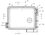
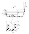
- FIG. 1 is a plan view showing an electrical junction box according to the first embodiment.
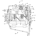
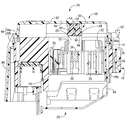
- FIG. 2 is an enlarged sectional view taken along the line II-II in FIG. 3 is an enlarged sectional view taken along the line III-III in FIG.
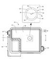
- FIG. 4 is a bottom view of the cover member shown in FIG. 5 is a cross-sectional view taken along the line VV in FIG.
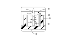
- FIG. 6 is an enlarged cross-sectional view showing another aspect of the heat radiating member holding unit according to the first embodiment, and corresponds to the inset shown in FIG. 5.
- the electrical junction box of the present disclosure is: (1) A box body provided with a component mounting portion on the surface on which an electrical component is mounted, and a cover member that covers the surface of the box body, and an inner surface of the top wall portion of the cover member, A heat radiating member holding portion protruding toward the electric component is provided, and the plastic heat radiating member held by the heat radiating member holding portion is an electric junction box in contact with the surface of the electric component.
- the inner surface of the top wall portion of the cover member is provided with the heat radiating member holding portion protruding toward the electric component, and has the plasticity held by the heat radiating member holding portion.
- the plastic heat dissipation member is in contact with the surface of the electrical component. Since the heat radiating member has plasticity, the contact pressure of the plastic heat radiating member in contact with the surface of the electrical component can be reduced. Further, the plastic heat dissipating member can be stably brought into contact with the surface of the electrical component by deforming it along the surface of the electrical component. Therefore, it is possible to avoid or reduce the possibility of damaging the electrical component, and to efficiently release the heat generated in the electrical component to the outside of the electrical junction box through the plastic heat radiating member and the cover member.
- heat dissipation member having plasticity for example, a heat dissipation silicone putty sheet that adheres well to unevenness in a clay shape, a heat dissipation silicone grease, or the like can be used.
- the heat radiating member holding portion projects from the inner surface of the top wall portion toward the box body, and is provided inside the peripheral wall portion.
- a shaft portion extending in the axial direction is included, and a part of the plastic heat radiating member preferably protrudes from the heat radiating member holding portion toward the electric component and is in contact with the surface of the electric component.
- the heat dissipating member holding portion includes a cylindrical peripheral wall portion and a shaft portion disposed inside thereof. Therefore, the plastic heat radiating member can be disposed at a predetermined position and held in contact with the peripheral wall portion and the shaft portion by simply pushing the plastic heat radiating member between the peripheral wall portion and the shaft portion. Thereby, it is possible to prevent the plastic heat radiating member from falling downward from the heat radiating member holding portion, and to hold the plastic heat radiating member reliably and stably. Moreover, a part of the plastic heat radiating member protruding from the heat radiating member holding portion is in contact with the surface of the electrical component. Therefore, the plastic heat radiating member can be brought into contact with the surface of the electric component without impairing the plasticity of the plastic heat radiating member. As a result, effects such as reduction in contact pressure and increase in contact area with electrical components can be advantageously realized.
- the said surrounding wall part is cylindrical shape and the said axial part is arrange
- the heat dissipating member holding portion has a cylindrical peripheral wall portion, the plastic heat dissipating member pushed into the inside is easily filled without any gap. Therefore, the contact area between the peripheral wall portion and the plastic heat radiating member can be reliably ensured, and stable holding of the plastic heat radiating member by the heat radiating member holding portion can be advantageously realized.
- the shaft portion and the peripheral wall portion are arranged concentrically, the plastic heat radiating member can be accommodated and arranged in the peripheral wall portion more evenly. As a result, stable holding of the plastic heat radiating member can be advantageously realized.
- a rib extending in parallel with the axial direction protrudes on the inner surface of the peripheral wall portion.
- the plastic heat radiating member is guided by the rib and smoothly press-fitted into the peripheral wall portion of the heat radiating member holding portion. Further, since the contact area between the plastic heat radiating member and the peripheral wall portion is increased by the rib, it is further advantageously prevented that the plastic heat radiating member falls downward from the heat radiating member holding portion.
- tip part of the said shaft part has extended toward the said box main body side rather than the protrusion edge part of the said surrounding wall part.
- the tip part of the shaft part extends toward the box body side from the protruding end part of the peripheral wall part. Therefore, it is possible to stably position and hold a part of the plastic heat radiating member that protrudes from the heat radiating member holding portion toward the electric component and contacts the surface of the electric component. Therefore, the plastic heat dissipation member can be reliably brought into contact with the surface of the electric component.
- tip part of the said axial part has the taper part which becomes tapered toward the said box main body side.
- the tip of the shaft has a taper that tapers toward the box body. Therefore, the plastic heat radiating member can be smoothly pushed into the peripheral wall portion of the heat radiating member holding portion using the shaft portion as a guide.
- the taper portion of the shaft portion has a widened portion whose dimension in the direction perpendicular to the shaft is larger than that of the shaft portion, and a step surface is formed between the widened portion and the shaft portion. Preferably it is.
- the taper portion of the shaft portion has a widened portion whose dimension in the direction perpendicular to the shaft is larger than that of the shaft portion, and a step surface is formed between the widened portion and the shaft portion.
- the electrical junction box 10 includes a box body 12, an upper cover 16 that is a cover member that covers the surface 14 of the box body 12, and a back surface of the box body 12. And a lower cover 20 that covers 18.
- “upper” means the upper side in FIGS. 2 and 3
- “lower” means the lower side in FIGS. 2 and 3
- “front” means the right side and “rear” in FIG. 1
- the longitudinal direction refers to the left-right direction in FIG. 1
- the width direction refers to the up-down direction in FIG.
- the box main body 12 has a long rectangular block shape as a whole.
- the box main body 12 is formed by injection molding with an insulating synthetic resin such as polypropylene (PP) or polyamide (PA). It is integrally formed.
- a relay mounting portion 22 On the front surface 14 of the box body 12, a relay mounting portion 22, a fusible link mounting portion 24, and a fuse mounting portion 26 constituting a component mounting portion are formed so as to open upward.
- a plurality of terminal receiving holes 28 are formed in the back surface 18 of the box body 12 so as to open downward, and a terminal fitting connected to a terminal of an electric wire (not shown) is provided. It is accommodated in the terminal accommodating hole 28.
- a bus bar (not shown) that constitutes an internal circuit is accommodated in a bus bar accommodation groove (not shown).
- a relay 30, a fusible link 32, or a fuse (not shown) as an electrical component is mounted on each relay mounting portion 22, fusible link mounting portion 24, and each fuse mounting portion 26.
- the tab terminal 36 protruding downward from the relay 30, the fusible link 32, or the fuse is conductively connected to the terminal fitting or bus bar provided at the end of the electric wire described above.
- an upper cover 16 that covers the surface 14 of the box main body 12 is provided at the upper end of the portion of the peripheral wall 38 of the box main body 12 that is opposite to the diagonal in the longitudinal direction.
- a locked portion 39 for locking and fixing is projected outward.
- a locking portion (not shown) for locking and fixing the lower cover 20 that covers the back surface 18 of the box body 12 is provided outwardly projecting from the lower end portion of the peripheral wall portion 38 of the box body 12.
- the peripheral wall portion 38 of the box body 12 has a double wall structure. Further, the peripheral wall portion 38 of the box body 12 is provided at the upper end portion of the peripheral wall portion 38 by a double wall structure and opens upward, and provided at the lower end portion of the peripheral wall portion 38 by a double wall structure. And a downward concave groove 40b that opens downward.
- the upper cover 16 has a substantially rectangular box shape that opens downward as a whole, and is an integrally molded product made of synthetic resin. More specifically, as shown in FIGS. 4 to 5, the upper cover 16 includes a top wall portion 42 having a substantially longitudinal rectangular shape and two protrusions projecting downward from the outer peripheral edge portion of the top wall portion 42.
- the peripheral wall portions 44 and 46 are provided. The two peripheral wall portions 44 and 46 are provided at positions corresponding to the peripheral wall portion 38 of the box body 12 in the inner surface 48 of the top wall portion 42.
- the two peripheral wall parts 44 and 46 are not enclosed by the double wall part 44 among the double wall part 44 and the inner surface 48 of the top wall part 42 which surround a substantially reverse L-shaped area
- the double wall portion 44 is configured by an inner wall portion 44a and an outer wall portion 44b extending in the circumferential direction with a gap therebetween.
- the outer wall portion 44b protrudes greatly downward from the inner wall portion 44a (see FIGS. 2 to 3), and intrusion of water or the like from the outside is advantageously prevented.
- FIG. 1 As shown in FIG.
- the cover wall portion 46 protrudes further downward than the outer wall portion 44 b of the double wall portion 44. Thereby, it is comprised so that the surrounding wall part 38 side of the front side (left side in FIG. 3) of the box main body 12 may be covered completely.
- the peripheral wall portion 38 on the front side of the box body 12 is provided with a power connection portion to which a power input terminal (not shown) connected to a positive power source of a battery or a positive power source of an alternator is bolted and fixed.
- a heat radiating member holding portion 52 protruding toward the relay 30 is provided on the inner surface 48 of the top wall portion 42 of the upper cover 16. More specifically, the heat radiating member holding portion 52 is positioned inside the peripheral wall portion 54 and a substantially cylindrical peripheral wall portion 54 that protrudes from the inner surface 48 of the top wall portion 42 toward the box body 12 side.
- the shaft portion 56 extends in the axial direction of the peripheral wall portion 54 (in FIG. 4, the direction perpendicular to the paper surface passing through the center of the peripheral wall portion 54 in the bottom view). That is, the shaft portion 56 is disposed concentrically with the peripheral wall portion 54.
- ribs 58 extending in a substantially triangular cross-sectional shape in parallel with the axial direction are protruded at eight locations spaced at equal intervals in the circumferential direction (see FIG. 4).
- the tip portion of the shaft portion 56 has a taper portion 60 that tapers toward the box body 12 as a whole, and extends toward the box body 12 side from the protruding end portion 62 of the peripheral wall portion 54. (See FIGS. 2 to 3).
- the heat radiating member holding portion 52 having such a configuration is filled with a plastic heat radiating member 64 so as to be held between the peripheral wall portion 54 and the shaft portion 56. It has become.
- the tip portion of the shaft portion 56 has a taper portion 60 that tapers toward the box body 12, so that the tip portion of the shaft portion 56 serves as a guide for plastic heat dissipation.
- the member 64 can be smoothly pushed into the peripheral wall portion 54 of the heat radiating member holding portion 52.
- the surrounding wall part 54 is made into the cylindrical shape, it is easy to fill the plastic heat radiating member 64 without a gap.
- the plastic heat radiating member 64 can be uniformly filled in the peripheral wall portion 54 and the stable plastic heat radiating member 64 can be held. Can advantageously be realized.
- plastic heat radiation member 64 for example, a heat-dissipating silicone putty sheet that adheres well to unevenness in a clay shape, a heat-dissipating silicone grease, or the like is used. A part of the plastic heat radiating member 64 protrudes from the protruding end 62 of the peripheral wall portion 54 constituting the heat radiating member holding portion 52 toward the relay 30 and is in contact with the surface 66 of the relay 30.
- the lower cover 20 is an integrally molded product formed from a synthetic resin, and has a substantially box shape opening upward as shown in FIGS.
- the upper end of the peripheral wall portion 68 of the lower cover 20 is engaged with the lock portion of the box body 12 at a position corresponding to a lock portion (not shown) of the box body 12 to fix the back surface 18 of the box body 12 in a cover state.
- a locked portion 70 to be held is projected outward.
- the heat radiation member holding portion 52 is projected from the inner surface 48 of the top wall portion 42 of the upper cover 16 toward the relay 30.
- a plastic heat dissipating member 64 filled in 52 is in contact with the surface 66 of the relay 30.
- the plastic heat radiation member 64 that is in contact with the surface 66 of the relay 30 has plasticity. Thereby, the contact pressure at the time of the contact to the surface 66 of the relay 30 can be reduced. Further, the plastic heat radiation member 64 can be stably brought into contact with the surface 66 of the relay 30 by being deformed along the surface 66 of the relay 30. Therefore, the possibility of damaging the relay 30 is avoided or reduced, and the heat generated in the relay 30 is efficiently passed through the plastic heat dissipation member 64 and the top wall portion 42 of the upper cover 16 to the outside of the electrical junction box 10. Can escape.
- the heat radiating member holding portion 52 includes a peripheral wall portion 54 and a shaft portion 56 provided therein. Therefore, the plastic heat dissipation member 64 is sandwiched between the peripheral wall portion 54 and the shaft portion 56 only by filling the inside of the peripheral wall portion 54 with the plastic heat dissipation member 64, and the plastic heat dissipation member 64 is connected to the peripheral wall of the heat dissipation member holding portion 52. It can be stably held in the portion 54. Moreover, a part of the plastic heat radiating member 64 protrudes from the protruding end 62 of the peripheral wall portion 54 of the heat radiating member holding portion 52 toward the relay 30 and is in contact with the surface 66 of the relay 30. Thereby, without impairing the plasticity of the plastic heat radiating member 64, the effect of reducing the contact pressure with respect to the surface 66 of the relay 30 of the plastic heat radiating member 64 and increasing the contact area can be advantageously realized.
- the tip end portion of the shaft portion 56 extends toward the box body 12 side from the protruding end portion 62 of the peripheral wall portion 54.
- the plastic heat radiating member 64 protrudes from the protruding end 62 of the peripheral wall portion 54 toward the relay 30 and the plastic heat radiating member 64 reliably contacts the surface 66 of the relay 30. It is said.
- the first embodiment has been described in detail as a specific example of the present disclosure, but the present disclosure is not limited to this specific description. Modifications, improvements, and the like within the scope that can achieve the object of the present disclosure are included in the present disclosure. For example, the following embodiments are also included in the technical scope of the present disclosure.
- maintenance part 52 had the taper part 60 tapering toward the box main body 12 side as a whole.
- the tapered portion 76 provided at the distal end portion of the shaft portion 74 is dimensioned in the direction perpendicular to the shaft portion 74, like the shaft portion 74 of the heat radiation member holding portion 72 as another aspect of the present embodiment shown in FIG. (R> r in FIG. 6) has a widened portion 78, and a stepped surface 80 may be formed between the widened portion 78 and the shaft portion 74. Accordingly, the stepped surface 80 formed between the widened portion 78 of the tapered portion 60 and the shaft portion 74 exhibits an anchor function, and a part of the plastic heat radiating member 64 protruding from the peripheral wall portion 54 of the heat radiating member holding portion 72. Can be held more stably.
- the stepped surface 80 is not limited to be parallel to the inner surface 48 of the top wall portion 42 shown in FIG. It may be inclined toward the inner surface 48 of the top wall portion 42 or may be inclined toward a direction away from the inner surface 48 of the ceiling wall portion 42.
- maintenance part 52,72 was made into the cylindrical shape, the thing of arbitrary shapes, such as square shape, polygonal shape, cross shape, and star shape, is employable. is there.
Landscapes
- Engineering & Computer Science (AREA)
- Power Engineering (AREA)
- Mechanical Engineering (AREA)
- Physics & Mathematics (AREA)
- Thermal Sciences (AREA)
- Microelectronics & Electronic Packaging (AREA)
- Architecture (AREA)
- Civil Engineering (AREA)
- Structural Engineering (AREA)
- Connection Or Junction Boxes (AREA)
- Cooling Or The Like Of Electrical Apparatus (AREA)
Priority Applications (2)
| Application Number | Priority Date | Filing Date | Title |
|---|---|---|---|
| CN201980039148.7A CN112262510A (zh) | 2018-06-11 | 2019-04-02 | 电连接箱 |
| US17/059,237 US11843228B2 (en) | 2018-06-11 | 2019-04-02 | Electrical connection box |
Applications Claiming Priority (2)
| Application Number | Priority Date | Filing Date | Title |
|---|---|---|---|
| JP2018-111308 | 2018-06-11 | ||
| JP2018111308A JP6948013B2 (ja) | 2018-06-11 | 2018-06-11 | 電気接続箱 |
Publications (1)
| Publication Number | Publication Date |
|---|---|
| WO2019239686A1 true WO2019239686A1 (ja) | 2019-12-19 |
Family
ID=68842077
Family Applications (1)
| Application Number | Title | Priority Date | Filing Date |
|---|---|---|---|
| PCT/JP2019/014697 Ceased WO2019239686A1 (ja) | 2018-06-11 | 2019-04-02 | 電気接続箱 |
Country Status (4)
| Country | Link |
|---|---|
| US (1) | US11843228B2 (enExample) |
| JP (1) | JP6948013B2 (enExample) |
| CN (1) | CN112262510A (enExample) |
| WO (1) | WO2019239686A1 (enExample) |
Families Citing this family (2)
| Publication number | Priority date | Publication date | Assignee | Title |
|---|---|---|---|---|
| JP7185651B2 (ja) * | 2020-03-05 | 2022-12-07 | 矢崎総業株式会社 | 電気接続箱 |
| JP7552412B2 (ja) * | 2021-02-12 | 2024-09-18 | 住友電装株式会社 | 電気接続箱 |
Citations (5)
| Publication number | Priority date | Publication date | Assignee | Title |
|---|---|---|---|---|
| JP2001326306A (ja) * | 2000-05-15 | 2001-11-22 | Ikeda Electric Co Ltd | 配線ブロックの収納構造 |
| JP2003289191A (ja) * | 2002-03-28 | 2003-10-10 | Denso Corp | 電子制御装置 |
| JP2010225674A (ja) * | 2009-03-19 | 2010-10-07 | Hitachi Automotive Systems Ltd | 制御ユニット |
| JP2012200141A (ja) * | 2012-04-27 | 2012-10-18 | Mitsubishi Electric Corp | 電子制御装置 |
| JP2014187063A (ja) * | 2013-03-21 | 2014-10-02 | Hitachi Automotive Systems Ltd | 電子制御装置 |
Family Cites Families (12)
| Publication number | Priority date | Publication date | Assignee | Title |
|---|---|---|---|---|
| JP3709960B2 (ja) | 1998-04-22 | 2005-10-26 | 矢崎総業株式会社 | 電気接続箱のカバーロック構造 |
| JP2007295706A (ja) | 2006-04-24 | 2007-11-08 | Furukawa Electric Co Ltd:The | 電気接続箱 |
| CN101783488B (zh) * | 2010-01-19 | 2012-01-04 | 浙江大学 | 分离式太阳能组件接线盒 |
| CN102291054B (zh) * | 2011-09-05 | 2013-08-14 | 浙江鑫辉光伏科技有限公司 | 光伏接线盒连接端子的安装结构 |
| JP6501116B2 (ja) * | 2015-08-03 | 2019-04-17 | 株式会社オートネットワーク技術研究所 | 電気接続箱 |
| JP6453195B2 (ja) * | 2015-09-29 | 2019-01-16 | 日立オートモティブシステムズ株式会社 | 車載制御装置 |
| US11014203B2 (en) * | 2016-07-11 | 2021-05-25 | Laird Technologies, Inc. | System for applying interface materials |
| JP2018164324A (ja) * | 2017-03-24 | 2018-10-18 | 株式会社オートネットワーク技術研究所 | 電気接続箱 |
| JP6958164B2 (ja) * | 2017-05-23 | 2021-11-02 | 株式会社オートネットワーク技術研究所 | コイル装置、基板付きコイル装置及び電気接続箱 |
| JP6930653B2 (ja) * | 2018-02-23 | 2021-09-01 | 住友電装株式会社 | 電気接続箱 |
| JP2021034685A (ja) * | 2019-08-29 | 2021-03-01 | 株式会社オートネットワーク技術研究所 | 電気接続箱 |
| JP7381540B2 (ja) * | 2021-10-19 | 2023-11-15 | 矢崎総業株式会社 | コネクタ及び組付構造 |
-
2018
- 2018-06-11 JP JP2018111308A patent/JP6948013B2/ja not_active Expired - Fee Related
-
2019
- 2019-04-02 CN CN201980039148.7A patent/CN112262510A/zh active Pending
- 2019-04-02 WO PCT/JP2019/014697 patent/WO2019239686A1/ja not_active Ceased
- 2019-04-02 US US17/059,237 patent/US11843228B2/en active Active
Patent Citations (5)
| Publication number | Priority date | Publication date | Assignee | Title |
|---|---|---|---|---|
| JP2001326306A (ja) * | 2000-05-15 | 2001-11-22 | Ikeda Electric Co Ltd | 配線ブロックの収納構造 |
| JP2003289191A (ja) * | 2002-03-28 | 2003-10-10 | Denso Corp | 電子制御装置 |
| JP2010225674A (ja) * | 2009-03-19 | 2010-10-07 | Hitachi Automotive Systems Ltd | 制御ユニット |
| JP2012200141A (ja) * | 2012-04-27 | 2012-10-18 | Mitsubishi Electric Corp | 電子制御装置 |
| JP2014187063A (ja) * | 2013-03-21 | 2014-10-02 | Hitachi Automotive Systems Ltd | 電子制御装置 |
Also Published As
| Publication number | Publication date |
|---|---|
| JP6948013B2 (ja) | 2021-10-13 |
| US11843228B2 (en) | 2023-12-12 |
| JP2019216504A (ja) | 2019-12-19 |
| CN112262510A (zh) | 2021-01-22 |
| US20210203137A1 (en) | 2021-07-01 |
Similar Documents
| Publication | Publication Date | Title |
|---|---|---|
| JP6278243B2 (ja) | 蓄電ユニット | |
| CN107531195B (zh) | 蓄电单元 | |
| JP6224042B2 (ja) | 電気接続箱およびワイヤハーネス | |
| CN105191036B (zh) | 电气连接箱 | |
| JP7226190B2 (ja) | 電気接続箱 | |
| JP2020127302A (ja) | 電気接続箱 | |
| JP6961173B2 (ja) | 電気接続箱 | |
| US20250070541A1 (en) | In-vehicle-component circuit unit | |
| JP2014082844A (ja) | 電気接続箱 | |
| JP4387314B2 (ja) | 電気接続箱 | |
| WO2017213145A1 (ja) | 基板ユニット | |
| JP5278680B2 (ja) | 車両用灯具 | |
| WO2014196333A1 (ja) | 電気接続箱 | |
| WO2019239686A1 (ja) | 電気接続箱 | |
| JP2011097711A (ja) | 電気接続箱 | |
| JP6575930B2 (ja) | 基板ユニット | |
| CN108933416A (zh) | 电气接线箱 | |
| WO2022215482A1 (ja) | 電気接続箱 | |
| JP6277110B2 (ja) | 電気接続箱 | |
| US12199374B2 (en) | Connector and mounting structure | |
| JP5532825B2 (ja) | 電気接続箱 | |
| JP2006271132A (ja) | 自動車用電気接続箱の固定構造 | |
| JP2019208342A (ja) | 電気接続箱 | |
| US20260024973A1 (en) | Electrical junction box | |
| WO2026079331A1 (ja) | 電気接続ユニット |
Legal Events
| Date | Code | Title | Description |
|---|---|---|---|
| 121 | Ep: the epo has been informed by wipo that ep was designated in this application |
Ref document number: 19820102 Country of ref document: EP Kind code of ref document: A1 |
|
| NENP | Non-entry into the national phase |
Ref country code: DE |
|
| 122 | Ep: pct application non-entry in european phase |
Ref document number: 19820102 Country of ref document: EP Kind code of ref document: A1 |