WO2019239686A1 - Electrical junction box - Google Patents
Electrical junction box Download PDFInfo
- Publication number
- WO2019239686A1 WO2019239686A1 PCT/JP2019/014697 JP2019014697W WO2019239686A1 WO 2019239686 A1 WO2019239686 A1 WO 2019239686A1 JP 2019014697 W JP2019014697 W JP 2019014697W WO 2019239686 A1 WO2019239686 A1 WO 2019239686A1
- Authority
- WO
- WIPO (PCT)
- Prior art keywords
- heat radiating
- radiating member
- wall portion
- peripheral wall
- box body
- Prior art date
Links
Images
Classifications
-
- H—ELECTRICITY
- H02—GENERATION; CONVERSION OR DISTRIBUTION OF ELECTRIC POWER
- H02B—BOARDS, SUBSTATIONS OR SWITCHING ARRANGEMENTS FOR THE SUPPLY OR DISTRIBUTION OF ELECTRIC POWER
- H02B1/00—Frameworks, boards, panels, desks, casings; Details of substations or switching arrangements
- H02B1/56—Cooling; Ventilation
-
- B—PERFORMING OPERATIONS; TRANSPORTING
- B60—VEHICLES IN GENERAL
- B60R—VEHICLES, VEHICLE FITTINGS, OR VEHICLE PARTS, NOT OTHERWISE PROVIDED FOR
- B60R16/00—Electric or fluid circuits specially adapted for vehicles and not otherwise provided for; Arrangement of elements of electric or fluid circuits specially adapted for vehicles and not otherwise provided for
- B60R16/02—Electric or fluid circuits specially adapted for vehicles and not otherwise provided for; Arrangement of elements of electric or fluid circuits specially adapted for vehicles and not otherwise provided for electric constitutive elements
- B60R16/023—Electric or fluid circuits specially adapted for vehicles and not otherwise provided for; Arrangement of elements of electric or fluid circuits specially adapted for vehicles and not otherwise provided for electric constitutive elements for transmission of signals between vehicle parts or subsystems
- B60R16/0238—Electrical distribution centers
-
- B—PERFORMING OPERATIONS; TRANSPORTING
- B60—VEHICLES IN GENERAL
- B60R—VEHICLES, VEHICLE FITTINGS, OR VEHICLE PARTS, NOT OTHERWISE PROVIDED FOR
- B60R16/00—Electric or fluid circuits specially adapted for vehicles and not otherwise provided for; Arrangement of elements of electric or fluid circuits specially adapted for vehicles and not otherwise provided for
- B60R16/02—Electric or fluid circuits specially adapted for vehicles and not otherwise provided for; Arrangement of elements of electric or fluid circuits specially adapted for vehicles and not otherwise provided for electric constitutive elements
- B60R16/023—Electric or fluid circuits specially adapted for vehicles and not otherwise provided for; Arrangement of elements of electric or fluid circuits specially adapted for vehicles and not otherwise provided for electric constitutive elements for transmission of signals between vehicle parts or subsystems
- B60R16/0239—Electronic boxes
-
- H—ELECTRICITY
- H02—GENERATION; CONVERSION OR DISTRIBUTION OF ELECTRIC POWER
- H02B—BOARDS, SUBSTATIONS OR SWITCHING ARRANGEMENTS FOR THE SUPPLY OR DISTRIBUTION OF ELECTRIC POWER
- H02B1/00—Frameworks, boards, panels, desks, casings; Details of substations or switching arrangements
- H02B1/26—Casings; Parts thereof or accessories therefor
- H02B1/46—Boxes; Parts thereof or accessories therefor
- H02B1/48—Mounting of devices therein
-
- H—ELECTRICITY
- H02—GENERATION; CONVERSION OR DISTRIBUTION OF ELECTRIC POWER
- H02G—INSTALLATION OF ELECTRIC CABLES OR LINES, OR OF COMBINED OPTICAL AND ELECTRIC CABLES OR LINES
- H02G3/00—Installations of electric cables or lines or protective tubing therefor in or on buildings, equivalent structures or vehicles
- H02G3/02—Details
- H02G3/08—Distribution boxes; Connection or junction boxes
- H02G3/16—Distribution boxes; Connection or junction boxes structurally associated with support for line-connecting terminals within the box
-
- H—ELECTRICITY
- H05—ELECTRIC TECHNIQUES NOT OTHERWISE PROVIDED FOR
- H05K—PRINTED CIRCUITS; CASINGS OR CONSTRUCTIONAL DETAILS OF ELECTRIC APPARATUS; MANUFACTURE OF ASSEMBLAGES OF ELECTRICAL COMPONENTS
- H05K7/00—Constructional details common to different types of electric apparatus
- H05K7/20—Modifications to facilitate cooling, ventilating, or heating
Definitions
- the present disclosure relates to an electrical junction box mounted on an automobile or the like, and particularly to an electrical junction box provided with a cover member that covers the surface of the box body.
- electrical connection boxes such as relay boxes, fuse boxes, and junction boxes have been used in the electrical system of automobiles, and a large number of electrical components such as relays and fuses are concentrated in such electrical connection boxes. As a result, the efficiency of electrical wiring and the maintenance such as replacement are improved.
- the electrical junction box includes a box body that accommodates an internal circuit composed of a bus bar, a printed circuit board, and the like.
- the surface of the box body is provided with a plurality of component mounting portions on which electrical components are mounted, and the surface of the box body is covered with a cover member.
- an object of the present invention is to provide an electric junction box having a novel structure capable of reducing the contact pressure of the heat radiating member with respect to the electric component and stably bringing the heat radiating member into contact with the surface of the electric component.
- An electrical connection box of the present disclosure includes a box body provided with a component mounting portion on a surface on which an electrical component is mounted, and a cover member that covers the surface of the box body, and the top wall portion of the cover member A heat radiating member holding portion protruding toward the electric component is provided on the inner surface of the electric component, and the plastic heat radiating member held by the heat radiating member holding portion is in contact with the surface of the electric component. It is a connection box.
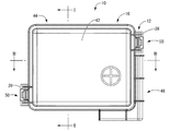
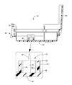
- FIG. 1 is a plan view showing an electrical junction box according to the first embodiment.
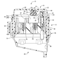
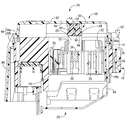
- FIG. 2 is an enlarged sectional view taken along the line II-II in FIG. 3 is an enlarged sectional view taken along the line III-III in FIG.
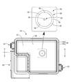
- FIG. 4 is a bottom view of the cover member shown in FIG. 5 is a cross-sectional view taken along the line VV in FIG.
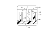
- FIG. 6 is an enlarged cross-sectional view showing another aspect of the heat radiating member holding unit according to the first embodiment, and corresponds to the inset shown in FIG. 5.
- the electrical junction box of the present disclosure is: (1) A box body provided with a component mounting portion on the surface on which an electrical component is mounted, and a cover member that covers the surface of the box body, and an inner surface of the top wall portion of the cover member, A heat radiating member holding portion protruding toward the electric component is provided, and the plastic heat radiating member held by the heat radiating member holding portion is an electric junction box in contact with the surface of the electric component.
- the inner surface of the top wall portion of the cover member is provided with the heat radiating member holding portion protruding toward the electric component, and has the plasticity held by the heat radiating member holding portion.
- the plastic heat dissipation member is in contact with the surface of the electrical component. Since the heat radiating member has plasticity, the contact pressure of the plastic heat radiating member in contact with the surface of the electrical component can be reduced. Further, the plastic heat dissipating member can be stably brought into contact with the surface of the electrical component by deforming it along the surface of the electrical component. Therefore, it is possible to avoid or reduce the possibility of damaging the electrical component, and to efficiently release the heat generated in the electrical component to the outside of the electrical junction box through the plastic heat radiating member and the cover member.
- heat dissipation member having plasticity for example, a heat dissipation silicone putty sheet that adheres well to unevenness in a clay shape, a heat dissipation silicone grease, or the like can be used.
- the heat radiating member holding portion projects from the inner surface of the top wall portion toward the box body, and is provided inside the peripheral wall portion.
- a shaft portion extending in the axial direction is included, and a part of the plastic heat radiating member preferably protrudes from the heat radiating member holding portion toward the electric component and is in contact with the surface of the electric component.
- the heat dissipating member holding portion includes a cylindrical peripheral wall portion and a shaft portion disposed inside thereof. Therefore, the plastic heat radiating member can be disposed at a predetermined position and held in contact with the peripheral wall portion and the shaft portion by simply pushing the plastic heat radiating member between the peripheral wall portion and the shaft portion. Thereby, it is possible to prevent the plastic heat radiating member from falling downward from the heat radiating member holding portion, and to hold the plastic heat radiating member reliably and stably. Moreover, a part of the plastic heat radiating member protruding from the heat radiating member holding portion is in contact with the surface of the electrical component. Therefore, the plastic heat radiating member can be brought into contact with the surface of the electric component without impairing the plasticity of the plastic heat radiating member. As a result, effects such as reduction in contact pressure and increase in contact area with electrical components can be advantageously realized.
- the said surrounding wall part is cylindrical shape and the said axial part is arrange
- the heat dissipating member holding portion has a cylindrical peripheral wall portion, the plastic heat dissipating member pushed into the inside is easily filled without any gap. Therefore, the contact area between the peripheral wall portion and the plastic heat radiating member can be reliably ensured, and stable holding of the plastic heat radiating member by the heat radiating member holding portion can be advantageously realized.
- the shaft portion and the peripheral wall portion are arranged concentrically, the plastic heat radiating member can be accommodated and arranged in the peripheral wall portion more evenly. As a result, stable holding of the plastic heat radiating member can be advantageously realized.
- a rib extending in parallel with the axial direction protrudes on the inner surface of the peripheral wall portion.
- the plastic heat radiating member is guided by the rib and smoothly press-fitted into the peripheral wall portion of the heat radiating member holding portion. Further, since the contact area between the plastic heat radiating member and the peripheral wall portion is increased by the rib, it is further advantageously prevented that the plastic heat radiating member falls downward from the heat radiating member holding portion.
- tip part of the said shaft part has extended toward the said box main body side rather than the protrusion edge part of the said surrounding wall part.
- the tip part of the shaft part extends toward the box body side from the protruding end part of the peripheral wall part. Therefore, it is possible to stably position and hold a part of the plastic heat radiating member that protrudes from the heat radiating member holding portion toward the electric component and contacts the surface of the electric component. Therefore, the plastic heat dissipation member can be reliably brought into contact with the surface of the electric component.
- tip part of the said axial part has the taper part which becomes tapered toward the said box main body side.
- the tip of the shaft has a taper that tapers toward the box body. Therefore, the plastic heat radiating member can be smoothly pushed into the peripheral wall portion of the heat radiating member holding portion using the shaft portion as a guide.
- the taper portion of the shaft portion has a widened portion whose dimension in the direction perpendicular to the shaft is larger than that of the shaft portion, and a step surface is formed between the widened portion and the shaft portion. Preferably it is.
- the taper portion of the shaft portion has a widened portion whose dimension in the direction perpendicular to the shaft is larger than that of the shaft portion, and a step surface is formed between the widened portion and the shaft portion.
- the electrical junction box 10 includes a box body 12, an upper cover 16 that is a cover member that covers the surface 14 of the box body 12, and a back surface of the box body 12. And a lower cover 20 that covers 18.
- “upper” means the upper side in FIGS. 2 and 3
- “lower” means the lower side in FIGS. 2 and 3
- “front” means the right side and “rear” in FIG. 1
- the longitudinal direction refers to the left-right direction in FIG. 1
- the width direction refers to the up-down direction in FIG.
- the box main body 12 has a long rectangular block shape as a whole.
- the box main body 12 is formed by injection molding with an insulating synthetic resin such as polypropylene (PP) or polyamide (PA). It is integrally formed.
- a relay mounting portion 22 On the front surface 14 of the box body 12, a relay mounting portion 22, a fusible link mounting portion 24, and a fuse mounting portion 26 constituting a component mounting portion are formed so as to open upward.
- a plurality of terminal receiving holes 28 are formed in the back surface 18 of the box body 12 so as to open downward, and a terminal fitting connected to a terminal of an electric wire (not shown) is provided. It is accommodated in the terminal accommodating hole 28.
- a bus bar (not shown) that constitutes an internal circuit is accommodated in a bus bar accommodation groove (not shown).
- a relay 30, a fusible link 32, or a fuse (not shown) as an electrical component is mounted on each relay mounting portion 22, fusible link mounting portion 24, and each fuse mounting portion 26.
- the tab terminal 36 protruding downward from the relay 30, the fusible link 32, or the fuse is conductively connected to the terminal fitting or bus bar provided at the end of the electric wire described above.
- an upper cover 16 that covers the surface 14 of the box main body 12 is provided at the upper end of the portion of the peripheral wall 38 of the box main body 12 that is opposite to the diagonal in the longitudinal direction.
- a locked portion 39 for locking and fixing is projected outward.
- a locking portion (not shown) for locking and fixing the lower cover 20 that covers the back surface 18 of the box body 12 is provided outwardly projecting from the lower end portion of the peripheral wall portion 38 of the box body 12.
- the peripheral wall portion 38 of the box body 12 has a double wall structure. Further, the peripheral wall portion 38 of the box body 12 is provided at the upper end portion of the peripheral wall portion 38 by a double wall structure and opens upward, and provided at the lower end portion of the peripheral wall portion 38 by a double wall structure. And a downward concave groove 40b that opens downward.
- the upper cover 16 has a substantially rectangular box shape that opens downward as a whole, and is an integrally molded product made of synthetic resin. More specifically, as shown in FIGS. 4 to 5, the upper cover 16 includes a top wall portion 42 having a substantially longitudinal rectangular shape and two protrusions projecting downward from the outer peripheral edge portion of the top wall portion 42.
- the peripheral wall portions 44 and 46 are provided. The two peripheral wall portions 44 and 46 are provided at positions corresponding to the peripheral wall portion 38 of the box body 12 in the inner surface 48 of the top wall portion 42.
- the two peripheral wall parts 44 and 46 are not enclosed by the double wall part 44 among the double wall part 44 and the inner surface 48 of the top wall part 42 which surround a substantially reverse L-shaped area
- the double wall portion 44 is configured by an inner wall portion 44a and an outer wall portion 44b extending in the circumferential direction with a gap therebetween.
- the outer wall portion 44b protrudes greatly downward from the inner wall portion 44a (see FIGS. 2 to 3), and intrusion of water or the like from the outside is advantageously prevented.
- FIG. 1 As shown in FIG.
- the cover wall portion 46 protrudes further downward than the outer wall portion 44 b of the double wall portion 44. Thereby, it is comprised so that the surrounding wall part 38 side of the front side (left side in FIG. 3) of the box main body 12 may be covered completely.
- the peripheral wall portion 38 on the front side of the box body 12 is provided with a power connection portion to which a power input terminal (not shown) connected to a positive power source of a battery or a positive power source of an alternator is bolted and fixed.
- a heat radiating member holding portion 52 protruding toward the relay 30 is provided on the inner surface 48 of the top wall portion 42 of the upper cover 16. More specifically, the heat radiating member holding portion 52 is positioned inside the peripheral wall portion 54 and a substantially cylindrical peripheral wall portion 54 that protrudes from the inner surface 48 of the top wall portion 42 toward the box body 12 side.
- the shaft portion 56 extends in the axial direction of the peripheral wall portion 54 (in FIG. 4, the direction perpendicular to the paper surface passing through the center of the peripheral wall portion 54 in the bottom view). That is, the shaft portion 56 is disposed concentrically with the peripheral wall portion 54.
- ribs 58 extending in a substantially triangular cross-sectional shape in parallel with the axial direction are protruded at eight locations spaced at equal intervals in the circumferential direction (see FIG. 4).
- the tip portion of the shaft portion 56 has a taper portion 60 that tapers toward the box body 12 as a whole, and extends toward the box body 12 side from the protruding end portion 62 of the peripheral wall portion 54. (See FIGS. 2 to 3).
- the heat radiating member holding portion 52 having such a configuration is filled with a plastic heat radiating member 64 so as to be held between the peripheral wall portion 54 and the shaft portion 56. It has become.
- the tip portion of the shaft portion 56 has a taper portion 60 that tapers toward the box body 12, so that the tip portion of the shaft portion 56 serves as a guide for plastic heat dissipation.
- the member 64 can be smoothly pushed into the peripheral wall portion 54 of the heat radiating member holding portion 52.
- the surrounding wall part 54 is made into the cylindrical shape, it is easy to fill the plastic heat radiating member 64 without a gap.
- the plastic heat radiating member 64 can be uniformly filled in the peripheral wall portion 54 and the stable plastic heat radiating member 64 can be held. Can advantageously be realized.
- plastic heat radiation member 64 for example, a heat-dissipating silicone putty sheet that adheres well to unevenness in a clay shape, a heat-dissipating silicone grease, or the like is used. A part of the plastic heat radiating member 64 protrudes from the protruding end 62 of the peripheral wall portion 54 constituting the heat radiating member holding portion 52 toward the relay 30 and is in contact with the surface 66 of the relay 30.
- the lower cover 20 is an integrally molded product formed from a synthetic resin, and has a substantially box shape opening upward as shown in FIGS.
- the upper end of the peripheral wall portion 68 of the lower cover 20 is engaged with the lock portion of the box body 12 at a position corresponding to a lock portion (not shown) of the box body 12 to fix the back surface 18 of the box body 12 in a cover state.
- a locked portion 70 to be held is projected outward.
- the heat radiation member holding portion 52 is projected from the inner surface 48 of the top wall portion 42 of the upper cover 16 toward the relay 30.
- a plastic heat dissipating member 64 filled in 52 is in contact with the surface 66 of the relay 30.
- the plastic heat radiation member 64 that is in contact with the surface 66 of the relay 30 has plasticity. Thereby, the contact pressure at the time of the contact to the surface 66 of the relay 30 can be reduced. Further, the plastic heat radiation member 64 can be stably brought into contact with the surface 66 of the relay 30 by being deformed along the surface 66 of the relay 30. Therefore, the possibility of damaging the relay 30 is avoided or reduced, and the heat generated in the relay 30 is efficiently passed through the plastic heat dissipation member 64 and the top wall portion 42 of the upper cover 16 to the outside of the electrical junction box 10. Can escape.
- the heat radiating member holding portion 52 includes a peripheral wall portion 54 and a shaft portion 56 provided therein. Therefore, the plastic heat dissipation member 64 is sandwiched between the peripheral wall portion 54 and the shaft portion 56 only by filling the inside of the peripheral wall portion 54 with the plastic heat dissipation member 64, and the plastic heat dissipation member 64 is connected to the peripheral wall of the heat dissipation member holding portion 52. It can be stably held in the portion 54. Moreover, a part of the plastic heat radiating member 64 protrudes from the protruding end 62 of the peripheral wall portion 54 of the heat radiating member holding portion 52 toward the relay 30 and is in contact with the surface 66 of the relay 30. Thereby, without impairing the plasticity of the plastic heat radiating member 64, the effect of reducing the contact pressure with respect to the surface 66 of the relay 30 of the plastic heat radiating member 64 and increasing the contact area can be advantageously realized.
- the tip end portion of the shaft portion 56 extends toward the box body 12 side from the protruding end portion 62 of the peripheral wall portion 54.
- the plastic heat radiating member 64 protrudes from the protruding end 62 of the peripheral wall portion 54 toward the relay 30 and the plastic heat radiating member 64 reliably contacts the surface 66 of the relay 30. It is said.
- the first embodiment has been described in detail as a specific example of the present disclosure, but the present disclosure is not limited to this specific description. Modifications, improvements, and the like within the scope that can achieve the object of the present disclosure are included in the present disclosure. For example, the following embodiments are also included in the technical scope of the present disclosure.
- maintenance part 52 had the taper part 60 tapering toward the box main body 12 side as a whole.
- the tapered portion 76 provided at the distal end portion of the shaft portion 74 is dimensioned in the direction perpendicular to the shaft portion 74, like the shaft portion 74 of the heat radiation member holding portion 72 as another aspect of the present embodiment shown in FIG. (R> r in FIG. 6) has a widened portion 78, and a stepped surface 80 may be formed between the widened portion 78 and the shaft portion 74. Accordingly, the stepped surface 80 formed between the widened portion 78 of the tapered portion 60 and the shaft portion 74 exhibits an anchor function, and a part of the plastic heat radiating member 64 protruding from the peripheral wall portion 54 of the heat radiating member holding portion 72. Can be held more stably.
- the stepped surface 80 is not limited to be parallel to the inner surface 48 of the top wall portion 42 shown in FIG. It may be inclined toward the inner surface 48 of the top wall portion 42 or may be inclined toward a direction away from the inner surface 48 of the ceiling wall portion 42.
- maintenance part 52,72 was made into the cylindrical shape, the thing of arbitrary shapes, such as square shape, polygonal shape, cross shape, and star shape, is employable. is there.
Abstract
Provided is an electrical junction box 10 comprising a box body 12 having a surface 14 provided with a component mounting portion 22 for mounting an electrical component 30 and a cover member 16 for covering the surface 14 of the box body 12, wherein: a heat dissipating member holder 52 protruding towards the electrical component 30 is provided on an inner surface 48 of a top plate 42 of the cover 16; and a plastic heat dissipating member 64 held by the heat dissipating member holder 52 is in contact with a surface 66 of the electrical component 30.
Description
本開示は、自動車等に搭載される電気接続箱に関し、特に、箱本体の表面を覆蓋するカバー部材を備えた電気接続箱に関するものである。
The present disclosure relates to an electrical junction box mounted on an automobile or the like, and particularly to an electrical junction box provided with a cover member that covers the surface of the box body.
従来から、自動車の電装系には、リレーボックスやヒューズボックス、ジャンクションボックス等の電気接続箱が用いられており、かかる電気接続箱に多数のリレーやヒューズ等の電気部品を集中して配設することによって、電気配線の効率化や交換等のメンテナンス性の向上が図られている。
Conventionally, electrical connection boxes such as relay boxes, fuse boxes, and junction boxes have been used in the electrical system of automobiles, and a large number of electrical components such as relays and fuses are concentrated in such electrical connection boxes. As a result, the efficiency of electrical wiring and the maintenance such as replacement are improved.
ところで、電気接続箱は、特開平11-307954号公報(特許文献1)等に記載されているとおり、バスバーやプリント基板等から構成される内部回路を収容する箱本体を備えている。箱本体の表面には、電気部品が装着される複数の部品装着部が設けられており、カバー部材によって箱本体の表面が覆蓋されるようになっている。
By the way, as described in JP-A-11-307954 (Patent Document 1) and the like, the electrical junction box includes a box body that accommodates an internal circuit composed of a bus bar, a printed circuit board, and the like. The surface of the box body is provided with a plurality of component mounting portions on which electrical components are mounted, and the surface of the box body is covered with a cover member.
ところが、近年の自動車電装品の増加に伴い、ヒューズやリレーなどの発熱性の高い電気部品が増え、電気接続箱は設置場所のスペースの関係からその大きさが制限されて、電気接続箱内の高密度化も進んでいる。特に、ヒューズの可溶部やリレーのコイル部は発熱量がきわめて大きい。このため、密閉した電気接続箱内に熱がこもり易くなり局部的な過熱が発生することにより、ヒューズやリレーの機能を損ねるおそれがあった。
However, with the recent increase in automotive electrical components, the number of highly heat-generating electrical components such as fuses and relays has increased, and the size of the electrical junction box has been limited due to the space of the installation location. Densification is also progressing. In particular, the fusible part of the fuse and the coil part of the relay generate extremely large amounts of heat. For this reason, heat tends to be trapped in the sealed electrical junction box, and local overheating may occur, which may impair the functions of the fuse and the relay.
これに対して、カバー部材の内面に放熱部材を固定し、箱本体の上面を覆蓋した状態で放熱部材がヒューズの表面に接触するようにする。これによりヒューズで発生した熱を外部に逃がす方法が、例えば特開2007-295706号公報(特許文献2)に記載されている。しかしながら、放熱部材は弾力性のある樹脂製とされていることから、電気部品の表面に放熱部材を接触させるためには比較的大きな力で放熱部材を電気部品に対して押圧する必要がある。それゆえ、電気部品にダメージを与えるおそれがあった。
In contrast, fix the heat dissipation member to the inner surface of the cover member so that the heat dissipation member contacts the surface of the fuse with the top surface of the box body covered. A method for releasing the heat generated by the fuse to the outside is described in, for example, Japanese Patent Application Laid-Open No. 2007-295706 (Patent Document 2). However, since the heat radiating member is made of an elastic resin, it is necessary to press the heat radiating member against the electric component with a relatively large force in order to bring the heat radiating member into contact with the surface of the electric component. Therefore, there is a risk of damaging the electrical components.
そこで、電気部品に対する放熱部材の接圧を低減しつつ、電気部品の表面に安定して放熱部材を接触させることが可能な、新規な構造の電気接続箱を提供することを目的とする。
Therefore, an object of the present invention is to provide an electric junction box having a novel structure capable of reducing the contact pressure of the heat radiating member with respect to the electric component and stably bringing the heat radiating member into contact with the surface of the electric component.
本開示の電気接続箱は、電気部品が装着される部品装着部が表面に設けられた箱本体と、前記箱本体の前記表面を覆蓋するカバー部材と、を備え、前記カバー部材の天壁部の内面には、前記電気部品に向かって突出する放熱部材保持部が設けられており、該放熱部材保持部に保持された可塑性放熱部材が、前記電気部品の表面に対して接触されている電気接続箱である。
An electrical connection box of the present disclosure includes a box body provided with a component mounting portion on a surface on which an electrical component is mounted, and a cover member that covers the surface of the box body, and the top wall portion of the cover member A heat radiating member holding portion protruding toward the electric component is provided on the inner surface of the electric component, and the plastic heat radiating member held by the heat radiating member holding portion is in contact with the surface of the electric component. It is a connection box.
本開示によれば、電気部品にダメージを与えるおそれを回避乃至は低減して、電気部品で発生した熱を可塑性放熱部材およびカバー部材を介して効率的に電気接続箱の外部に逃がすことができる。
According to the present disclosure, it is possible to avoid or reduce the possibility of damaging the electrical component, and to efficiently release the heat generated in the electrical component to the outside of the electrical junction box through the plastic heat dissipation member and the cover member. .
<本開示の実施形態の説明>
最初に本開示の実施態様を列記して説明する。
本開示の電気接続箱は、
(1)電気部品が装着される部品装着部が表面に設けられた箱本体と、前記箱本体の前記表面を覆蓋するカバー部材と、を備え、前記カバー部材の天壁部の内面には、前記電気部品に向かって突出する放熱部材保持部が設けられており、該放熱部材保持部に保持された可塑性放熱部材が、前記電気部品の表面に対して接触されている電気接続箱である。 <Description of Embodiment of Present Disclosure>
First, embodiments of the present disclosure will be listed and described.
The electrical junction box of the present disclosure is:
(1) A box body provided with a component mounting portion on the surface on which an electrical component is mounted, and a cover member that covers the surface of the box body, and an inner surface of the top wall portion of the cover member, A heat radiating member holding portion protruding toward the electric component is provided, and the plastic heat radiating member held by the heat radiating member holding portion is an electric junction box in contact with the surface of the electric component.
本開示の電気接続箱によれば、カバー部材の天壁部の内面には、電気部品に向かって突出する放熱部材保持部が設けられており、放熱部材保持部に保持されている可塑性を有する可塑性放熱部材が、電気部品の表面に対して接触している。放熱部材が可塑性を有していることから、電気部品の表面に接触される可塑性放熱部材の接圧を低減できる。また、可塑性放熱部材を電気部品の表面に沿って変形させることにより安定して電気部品の表面に接触させることができる。それゆえ、電気部品にダメージを与えるおそれを回避乃至は低減して、電気部品で発生した熱を可塑性放熱部材およびカバー部材を介して効率的に電気接続箱の外部に逃がすことができる。
According to the electrical junction box of the present disclosure, the inner surface of the top wall portion of the cover member is provided with the heat radiating member holding portion protruding toward the electric component, and has the plasticity held by the heat radiating member holding portion. The plastic heat dissipation member is in contact with the surface of the electrical component. Since the heat radiating member has plasticity, the contact pressure of the plastic heat radiating member in contact with the surface of the electrical component can be reduced. Further, the plastic heat dissipating member can be stably brought into contact with the surface of the electrical component by deforming it along the surface of the electrical component. Therefore, it is possible to avoid or reduce the possibility of damaging the electrical component, and to efficiently release the heat generated in the electrical component to the outside of the electrical junction box through the plastic heat radiating member and the cover member.
なお、可塑性を有する放熱部材としては、例えば粘土状で凹凸に良く密着する放熱用のシリコーン製のパテシートや、放熱用のシリコーン製のグリース等が採用可能である。
As the heat dissipation member having plasticity, for example, a heat dissipation silicone putty sheet that adheres well to unevenness in a clay shape, a heat dissipation silicone grease, or the like can be used.
(2)前記放熱部材保持部が、前記天壁部の前記内面より前記箱本体側に向かって突出して設けられた筒形状の周壁部と、該周壁部の内部に位置して該周壁部の軸方向に延びる軸部を含んでおり、前記可塑性放熱部材の一部が前記放熱部材保持部から前記電気部品に向かって突出して前記電気部品の前記表面に接触されていることが好ましい。
(2) The heat radiating member holding portion projects from the inner surface of the top wall portion toward the box body, and is provided inside the peripheral wall portion. A shaft portion extending in the axial direction is included, and a part of the plastic heat radiating member preferably protrudes from the heat radiating member holding portion toward the electric component and is in contact with the surface of the electric component.
放熱部材保持部が、筒形状の周壁部とその内部に配設された軸部を含んでいる。それゆえ、周壁部と軸部の間に可塑性放熱部材を充填するように押し込むだけで、周壁部と軸部により可塑性放熱部材を所定位置に配置し接触保持することができる。これにより、可塑性放熱部材が放熱部材保持部から下方に向かって抜け落ちることを防止し、可塑性放熱部材を確実且つ安定して保持することができる。しかも、放熱部材保持部から突出した可塑性放熱部材の一部が電気部品の表面に接触されている。それゆえ、可塑性放熱部材の可塑性を損なうことなく、可塑性放熱部材を電気部品の表面に接触させることができる。その結果、接圧の低減や電気部品との接触面積の増大といった効果を有利に実現することができる。
The heat dissipating member holding portion includes a cylindrical peripheral wall portion and a shaft portion disposed inside thereof. Therefore, the plastic heat radiating member can be disposed at a predetermined position and held in contact with the peripheral wall portion and the shaft portion by simply pushing the plastic heat radiating member between the peripheral wall portion and the shaft portion. Thereby, it is possible to prevent the plastic heat radiating member from falling downward from the heat radiating member holding portion, and to hold the plastic heat radiating member reliably and stably. Moreover, a part of the plastic heat radiating member protruding from the heat radiating member holding portion is in contact with the surface of the electrical component. Therefore, the plastic heat radiating member can be brought into contact with the surface of the electric component without impairing the plasticity of the plastic heat radiating member. As a result, effects such as reduction in contact pressure and increase in contact area with electrical components can be advantageously realized.
(3)前記周壁部が円筒形状であり、前記軸部が同心状に配設されていることが好ましい。
(3) It is preferable that the said surrounding wall part is cylindrical shape and the said axial part is arrange | positioned concentrically.
放熱部材保持部が、円筒形状の周壁部を有していることから、内部に押し込まれる可塑性放熱部材が隙間なく充填され易い。それゆえ、周壁部と可塑性放熱部材の接触面積を確実に確保することができ、放熱部材保持部による可塑性放熱部材の安定した保持を有利に実現できる。加えて、軸部と周壁部が同心状に配されていることから、可塑性放熱部材をより均等に周壁部内に収容配置することができる。その結果、安定的な可塑性放熱部材の保持が有利に実現され得る。
Since the heat dissipating member holding portion has a cylindrical peripheral wall portion, the plastic heat dissipating member pushed into the inside is easily filled without any gap. Therefore, the contact area between the peripheral wall portion and the plastic heat radiating member can be reliably ensured, and stable holding of the plastic heat radiating member by the heat radiating member holding portion can be advantageously realized. In addition, since the shaft portion and the peripheral wall portion are arranged concentrically, the plastic heat radiating member can be accommodated and arranged in the peripheral wall portion more evenly. As a result, stable holding of the plastic heat radiating member can be advantageously realized.
(4)前記周壁部の内面には前記軸方向に平行に延びるリブが突設されていることが好ましい。
(4) It is preferable that a rib extending in parallel with the axial direction protrudes on the inner surface of the peripheral wall portion.
周壁部の内面には軸方向に平行に延びるリブが突設されていることから、可塑性放熱部材がリブにガイドされて放熱部材保持部の周壁部内にスムーズに圧入される。また、リブにより可塑性放熱部材と周壁部との接触面積が増大することから、可塑性放熱部材が放熱部材保持部から下方に向かって抜け落ちることが一層有利に防止されている。
Since ribs extending in parallel to the axial direction project from the inner surface of the peripheral wall portion, the plastic heat radiating member is guided by the rib and smoothly press-fitted into the peripheral wall portion of the heat radiating member holding portion. Further, since the contact area between the plastic heat radiating member and the peripheral wall portion is increased by the rib, it is further advantageously prevented that the plastic heat radiating member falls downward from the heat radiating member holding portion.
(5)前記軸部の先端部が前記周壁部の突出端部よりも前記箱本体側に向かって延び出していることが好ましい。
(5) It is preferable that the front-end | tip part of the said shaft part has extended toward the said box main body side rather than the protrusion edge part of the said surrounding wall part.
軸部の先端部が周壁部の突出端部よりも箱本体側に向かって延び出している。これにより、放熱部材保持部から電気部品に向かって突出して電気部品の表面に接触される可塑性放熱部材の一部を安定して位置決め保持することができる。それゆえ、電気部品の表面に可塑性放熱部材を確実に接触させることができる。
The tip part of the shaft part extends toward the box body side from the protruding end part of the peripheral wall part. Thereby, it is possible to stably position and hold a part of the plastic heat radiating member that protrudes from the heat radiating member holding portion toward the electric component and contacts the surface of the electric component. Therefore, the plastic heat dissipation member can be reliably brought into contact with the surface of the electric component.
(6)前記軸部の前記先端部が、前記箱本体側に向かって先細となるテーパ部を有していることが好ましい。
(6) It is preferable that the front-end | tip part of the said axial part has the taper part which becomes tapered toward the said box main body side.
軸部の先端部が、箱本体側に向かって先細となるテーパ部を有している。それゆえ、軸部をガイドとして可塑性放熱部材を放熱部材保持部の周壁部内にスムーズに押し入れることができる。
The tip of the shaft has a taper that tapers toward the box body. Therefore, the plastic heat radiating member can be smoothly pushed into the peripheral wall portion of the heat radiating member holding portion using the shaft portion as a guide.
(7)前記軸部の前記テーパ部が、前記軸部よりも軸直角方向の寸法が大きくされた拡幅部を有しており、前記拡幅部と前記軸部の間に段差面が形成されていることが好ましい。
(7) The taper portion of the shaft portion has a widened portion whose dimension in the direction perpendicular to the shaft is larger than that of the shaft portion, and a step surface is formed between the widened portion and the shaft portion. Preferably it is.
軸部のテーパ部が、軸部よりも軸直角方向の寸法が大きくされた拡幅部を有しており、拡幅部と軸部の間に段差面が形成されている。これにより、テーパ部がアンカー機能を発揮して、放熱部材保持部から突出する可塑性放熱部材の一部をより一層安定して保持することができる。
The taper portion of the shaft portion has a widened portion whose dimension in the direction perpendicular to the shaft is larger than that of the shaft portion, and a step surface is formed between the widened portion and the shaft portion. Thereby, a taper part exhibits an anchor function and can hold | maintain a part of plastic heat radiating member which protrudes from a heat radiating member holding | maintenance part still more stably.
<本開示の実施形態の詳細>
本開示の電気接続箱の具体例を、以下に図面を参照しつつ説明する。なお、本開示はこれらの例示に限定されるものではなく、特許請求の範囲によって示され、特許請求の範囲と均等の意味および範囲内でのすべての変更が含まれることが意図される。 <Details of Embodiment of Present Disclosure>
Specific examples of the electrical connection box of the present disclosure will be described below with reference to the drawings. It should be noted that the present disclosure is not limited to these exemplifications, and is shown by the scope of the claims, and is intended to include all modifications within the meaning and scope equivalent to the scope of the claims.
図1~5に、本開示の実施形態1としての電気接続箱10を示す。より詳細には、電気接続箱10は、図2~3に示されているように、箱本体12と、箱本体12の表面14を覆蓋するカバー部材たるアッパカバー16と、箱本体12の裏面18を覆蓋するロアカバー20、とを含んで構成されている。なお、以下の説明において、上方とは、図2~3中の上方、下方とは、図2~3中の下方を言い、また前方とは、図1中の右方、後方とは、図1中の左方を言い、さらに長手方向とは、図1中の左右方向、幅方向とは、図1中の上下方向を言うものとする。
1 to 5 show an electrical junction box 10 as Embodiment 1 of the present disclosure. More specifically, as shown in FIGS. 2 to 3, the electrical junction box 10 includes a box body 12, an upper cover 16 that is a cover member that covers the surface 14 of the box body 12, and a back surface of the box body 12. And a lower cover 20 that covers 18. In the following description, “upper” means the upper side in FIGS. 2 and 3, “lower” means the lower side in FIGS. 2 and 3, and “front” means the right side and “rear” in FIG. 1, the longitudinal direction refers to the left-right direction in FIG. 1, and the width direction refers to the up-down direction in FIG.
箱本体12は、図1~3に示されているように、全体として長手矩形ブロック形状を呈しており、例えばポリプロピレン(PP)、ポリアミド(PA)等の絶縁性の合成樹脂により射出成形等によって一体形成されている。箱本体12の表面14には、部品装着部を構成するリレー装着部22やヒュージブルリンク装着部24やヒューズ装着部26が、上方に向かって開口形成されている。図2~3に示されているように、箱本体12の裏面18には、複数の端子収容孔28が下方に向かって開口形成されており、図示しない電線の端末に接続された端子金具が端子収容孔28に収容配置されるようになっている。また、箱本体12には、内部回路を構成する図示しないバスバーが、図示しないバスバー収容溝等に収容配置されるようになっている。
As shown in FIGS. 1 to 3, the box main body 12 has a long rectangular block shape as a whole. For example, the box main body 12 is formed by injection molding with an insulating synthetic resin such as polypropylene (PP) or polyamide (PA). It is integrally formed. On the front surface 14 of the box body 12, a relay mounting portion 22, a fusible link mounting portion 24, and a fuse mounting portion 26 constituting a component mounting portion are formed so as to open upward. As shown in FIGS. 2 to 3, a plurality of terminal receiving holes 28 are formed in the back surface 18 of the box body 12 so as to open downward, and a terminal fitting connected to a terminal of an electric wire (not shown) is provided. It is accommodated in the terminal accommodating hole 28. In the box body 12, a bus bar (not shown) that constitutes an internal circuit is accommodated in a bus bar accommodation groove (not shown).
箱本体12の表面14側から、各リレー装着部22やヒュージブルリンク装着部24や各ヒューズ装着部26に対して、電気部品としてのリレー30やヒュージブルリンク32や図示しないヒューズが装着される。これにより、リレー30やヒュージブルリンク32やヒューズから下方に向かって突出するタブ端子36が上述した電線の端末に設けられた端子金具やバスバー等に導通接続される。
From the surface 14 side of the box body 12, a relay 30, a fusible link 32, or a fuse (not shown) as an electrical component is mounted on each relay mounting portion 22, fusible link mounting portion 24, and each fuse mounting portion 26. . As a result, the tab terminal 36 protruding downward from the relay 30, the fusible link 32, or the fuse is conductively connected to the terminal fitting or bus bar provided at the end of the electric wire described above.
また、図1,3に示されているように、箱本体12の周壁部38の長手方向の斜向かいに対向する部分の上端部には、箱本体12の表面14を覆蓋するアッパカバー16をロック固定するための被ロック部39が外方に向かって突設されている。さらに、箱本体12の周壁部38の下端部には、箱本体12の裏面18を覆蓋するロアカバー20をロック固定するための図示しないロック部が外方に向かって突設されている。
As shown in FIGS. 1 and 3, an upper cover 16 that covers the surface 14 of the box main body 12 is provided at the upper end of the portion of the peripheral wall 38 of the box main body 12 that is opposite to the diagonal in the longitudinal direction. A locked portion 39 for locking and fixing is projected outward. Further, a locking portion (not shown) for locking and fixing the lower cover 20 that covers the back surface 18 of the box body 12 is provided outwardly projecting from the lower end portion of the peripheral wall portion 38 of the box body 12.
加えて、図2~3に示されているように、箱本体12の周壁部38は二重壁構造とされている。また、箱本体12の周壁部38は、二重壁構造によって周壁部38の上端部に設けられ上方に向かって開口する上方凹溝部40aと、二重壁構造によって周壁部38の下端部に設けられ下方に向かって開口する下方凹溝部40bと、を備えている。
In addition, as shown in FIGS. 2 to 3, the peripheral wall portion 38 of the box body 12 has a double wall structure. Further, the peripheral wall portion 38 of the box body 12 is provided at the upper end portion of the peripheral wall portion 38 by a double wall structure and opens upward, and provided at the lower end portion of the peripheral wall portion 38 by a double wall structure. And a downward concave groove 40b that opens downward.
アッパカバー16は、図1~5に示されているように、全体として下方に向かって開口する略矩形箱体形状を有しており、合成樹脂から形成された一体成形品とされている。より詳細には、図4~5に示されているように、アッパカバー16は、略長手矩形状の天壁部42と、天壁部42の外周縁部から下方に向って突出する2つの周壁部44,46を備えて構成されている。2つの周壁部44,46は、天壁部42の内面48のうち箱本体12の周壁部38に対応する位置に設けられている。また、2つの周壁部44,46は、底面視で略逆L字状の領域を囲む二重壁部44と、天壁部42の内面48のうち二重壁部44で囲まれていない(図4中、左手前側)領域の外周縁部から下方に向って突出するカバー壁部46と、を含んで構成されている。二重壁部44は、図2~5に示されているように、周方向に延出する内壁部44aおよび外壁部44bが隙間を隔てて配設されて構成されている。外壁部44bは内壁部44aよりも下方に向かって大きく突設されており(図2~3参照)、外部からの水等の浸入が有利に防止されている。カバー壁部46は、例えば図3に示されているように、二重壁部44の外壁部44bよりもさらに下方に向かって突設されている。これにより、箱本体12の前方側(図3中、左側)の周壁部38側を全体を完全に覆うように構成されている。箱本体12の前方側の周壁部38には、例えばバッテリのプラス電源やオルタネータのプラス電源に接続された図示しない電源入力端子がボルト締め固定されている電源接続部が設けられている。
As shown in FIGS. 1 to 5, the upper cover 16 has a substantially rectangular box shape that opens downward as a whole, and is an integrally molded product made of synthetic resin. More specifically, as shown in FIGS. 4 to 5, the upper cover 16 includes a top wall portion 42 having a substantially longitudinal rectangular shape and two protrusions projecting downward from the outer peripheral edge portion of the top wall portion 42. The peripheral wall portions 44 and 46 are provided. The two peripheral wall portions 44 and 46 are provided at positions corresponding to the peripheral wall portion 38 of the box body 12 in the inner surface 48 of the top wall portion 42. Moreover, the two peripheral wall parts 44 and 46 are not enclosed by the double wall part 44 among the double wall part 44 and the inner surface 48 of the top wall part 42 which surround a substantially reverse L-shaped area | region by bottom view ( 4, the cover wall 46 protrudes downward from the outer peripheral edge of the region on the left front side). As shown in FIGS. 2 to 5, the double wall portion 44 is configured by an inner wall portion 44a and an outer wall portion 44b extending in the circumferential direction with a gap therebetween. The outer wall portion 44b protrudes greatly downward from the inner wall portion 44a (see FIGS. 2 to 3), and intrusion of water or the like from the outside is advantageously prevented. For example, as shown in FIG. 3, the cover wall portion 46 protrudes further downward than the outer wall portion 44 b of the double wall portion 44. Thereby, it is comprised so that the surrounding wall part 38 side of the front side (left side in FIG. 3) of the box main body 12 may be covered completely. The peripheral wall portion 38 on the front side of the box body 12 is provided with a power connection portion to which a power input terminal (not shown) connected to a positive power source of a battery or a positive power source of an alternator is bolted and fixed.
また、図1,3~4に示されているように、アッパカバー16の周壁部を構成する二重壁部44の長手方向の斜向かいに対向する部分の下端部において、箱本体12に設けられた被ロック部39に対応する位置には、被ロック部39にロック嵌合されるロック部50が外方に向かって突設されている。
Also, as shown in FIGS. 1 and 3 to 4, it is provided in the box body 12 at the lower end portion of the double wall portion 44 constituting the peripheral wall portion of the upper cover 16 that is opposed to the diagonally opposite in the longitudinal direction. At a position corresponding to the locked part 39 formed, a lock part 50 that is locked and fitted to the locked part 39 is projected outward.
さらに、図2~5に示されているように、アッパカバー16の天壁部42の内面48には、リレー30に向かって突出する放熱部材保持部52が設けられている。より詳細には、放熱部材保持部52は、天壁部42の内面48より箱本体12側に向かって突出して設けられた略円筒形状の周壁部54と、周壁部54の内部に位置して周壁部54の軸方向(図4中、底面視における周壁部54の中心を通る紙面に垂直な方向)に延びる軸部56を含んで構成されている。すなわち、軸部56は周壁部54の同心状に配設されている。加えて、周壁部54の内面には、周方向の等間隔に離隔した8箇所において軸方向に平行に略三角断面形状で延びるリブ58が突設されている(図4参照)。また、軸部56の先端部が、全体として箱本体12側に向かって先細となるテーパ部60を有しており、周壁部54の突出端部62よりも箱本体12側に向かって延び出している(図2~3参照)。
Further, as shown in FIGS. 2 to 5, a heat radiating member holding portion 52 protruding toward the relay 30 is provided on the inner surface 48 of the top wall portion 42 of the upper cover 16. More specifically, the heat radiating member holding portion 52 is positioned inside the peripheral wall portion 54 and a substantially cylindrical peripheral wall portion 54 that protrudes from the inner surface 48 of the top wall portion 42 toward the box body 12 side. The shaft portion 56 extends in the axial direction of the peripheral wall portion 54 (in FIG. 4, the direction perpendicular to the paper surface passing through the center of the peripheral wall portion 54 in the bottom view). That is, the shaft portion 56 is disposed concentrically with the peripheral wall portion 54. In addition, on the inner surface of the peripheral wall portion 54, ribs 58 extending in a substantially triangular cross-sectional shape in parallel with the axial direction are protruded at eight locations spaced at equal intervals in the circumferential direction (see FIG. 4). Further, the tip portion of the shaft portion 56 has a taper portion 60 that tapers toward the box body 12 as a whole, and extends toward the box body 12 side from the protruding end portion 62 of the peripheral wall portion 54. (See FIGS. 2 to 3).
図2~3に示されているように、このような構成とされた放熱部材保持部52に対して、可塑性放熱部材64が充填されて周壁部54と軸部56の間に保持されるようになっている。可塑性放熱部材64を充填する際には、軸部56の先端部が箱本体12側に向かって先細となるテーパ部60を有していることから、軸部56の先端部をガイドとして可塑性放熱部材64を放熱部材保持部52の周壁部54内にスムーズに押し入れることができる。また、周壁部54が円筒形状とされていることから、可塑性放熱部材64が隙間なく充填され易い。さらに、周壁部54の内面にはリブ58が突設されていることから、可塑性放熱部材64の周壁部54との接触面積を増大させて放熱部材保持部52による可塑性放熱部材64の安定した保持を有利に実現できる。しかも、放熱部材保持部52の周壁部54と軸部56が同心状に配置されていることから、可塑性放熱部材64を均等に周壁部54内に充填でき、安定的な可塑性放熱部材64の保持が有利に実現され得る。なお、可塑性放熱部材64としては、例えば粘土状で凹凸に良く密着する放熱用のシリコーン製のパテシートや、放熱用のシリコーン製のグリース等が用いられている。また、可塑性放熱部材64の一部が、放熱部材保持部52を構成する周壁部54の突出端部62からリレー30に向かって突出して、リレー30の表面66に接触されている。
As shown in FIGS. 2 to 3, the heat radiating member holding portion 52 having such a configuration is filled with a plastic heat radiating member 64 so as to be held between the peripheral wall portion 54 and the shaft portion 56. It has become. When filling the plastic heat radiating member 64, the tip portion of the shaft portion 56 has a taper portion 60 that tapers toward the box body 12, so that the tip portion of the shaft portion 56 serves as a guide for plastic heat dissipation. The member 64 can be smoothly pushed into the peripheral wall portion 54 of the heat radiating member holding portion 52. Moreover, since the surrounding wall part 54 is made into the cylindrical shape, it is easy to fill the plastic heat radiating member 64 without a gap. Further, since ribs 58 project from the inner surface of the peripheral wall portion 54, the contact area of the plastic heat radiating member 64 with the peripheral wall portion 54 is increased, and the plastic heat radiating member 64 is stably held by the heat radiating member holding portion 52. Can be realized advantageously. Moreover, since the peripheral wall portion 54 and the shaft portion 56 of the heat radiating member holding portion 52 are arranged concentrically, the plastic heat radiating member 64 can be uniformly filled in the peripheral wall portion 54 and the stable plastic heat radiating member 64 can be held. Can advantageously be realized. As the plastic heat radiation member 64, for example, a heat-dissipating silicone putty sheet that adheres well to unevenness in a clay shape, a heat-dissipating silicone grease, or the like is used. A part of the plastic heat radiating member 64 protrudes from the protruding end 62 of the peripheral wall portion 54 constituting the heat radiating member holding portion 52 toward the relay 30 and is in contact with the surface 66 of the relay 30.
このようなアッパカバー16を箱本体12の表面14を覆蓋するように組み付ける際には、図2~3に示されているように、アッパカバー16の二重壁部44の内壁部44aを、箱本体12の周壁部38の上方凹溝部40aに挿し入れる。これにより、アッパカバー16の各ロック部50が箱本体12の被ロック部39に係合して、アッパカバー16が箱本体12の表面14を覆蓋した状態にロック固定される。
When assembling such an upper cover 16 so as to cover the surface 14 of the box body 12, the inner wall portion 44a of the double wall portion 44 of the upper cover 16 is attached as shown in FIGS. The box body 12 is inserted into the upper concave groove portion 40 a of the peripheral wall portion 38. Thereby, each lock part 50 of the upper cover 16 engages with the locked part 39 of the box body 12, and the upper cover 16 is locked and fixed in a state of covering the surface 14 of the box body 12.
ロアカバー20は、合成樹脂から形成された一体成形品とされており、図2~3に示されているように、上方に開口する略箱体形状とされている。また、ロアカバー20の周壁部68の上端部には、箱本体12の図示しないロック部に対応する位置において、箱本体12のロック部と係合して箱本体12の裏面18を覆蓋状態に固定保持する被ロック部70が外方に向かって突設されている。
The lower cover 20 is an integrally molded product formed from a synthetic resin, and has a substantially box shape opening upward as shown in FIGS. The upper end of the peripheral wall portion 68 of the lower cover 20 is engaged with the lock portion of the box body 12 at a position corresponding to a lock portion (not shown) of the box body 12 to fix the back surface 18 of the box body 12 in a cover state. A locked portion 70 to be held is projected outward.
このような構造とされた電気接続箱10によれば、アッパカバー16の天壁部42の内面48には、リレー30に向かって放熱部材保持部52が突設されており、放熱部材保持部52に充填された可塑性放熱部材64がリレー30の表面66に接触されている。リレー30の表面66に接触されている可塑性放熱部材64は可塑性を有している。これにより、リレー30の表面66への接触時の接圧を低減できる。また、可塑性放熱部材64がリレー30の表面66に沿って変形することで安定してリレー30の表面66に対して接触させることができる。それゆえ、リレー30にダメージを与えるおそれを回避乃至は低減して、リレー30で発生した熱を可塑性放熱部材64およびアッパカバー16の天壁部42を介して効率的に電気接続箱10の外部に逃がすことができる。
According to the electrical junction box 10 having such a structure, the heat radiation member holding portion 52 is projected from the inner surface 48 of the top wall portion 42 of the upper cover 16 toward the relay 30. A plastic heat dissipating member 64 filled in 52 is in contact with the surface 66 of the relay 30. The plastic heat radiation member 64 that is in contact with the surface 66 of the relay 30 has plasticity. Thereby, the contact pressure at the time of the contact to the surface 66 of the relay 30 can be reduced. Further, the plastic heat radiation member 64 can be stably brought into contact with the surface 66 of the relay 30 by being deformed along the surface 66 of the relay 30. Therefore, the possibility of damaging the relay 30 is avoided or reduced, and the heat generated in the relay 30 is efficiently passed through the plastic heat dissipation member 64 and the top wall portion 42 of the upper cover 16 to the outside of the electrical junction box 10. Can escape.
また、放熱部材保持部52は、周壁部54とその内部に設けられた軸部56を含んで構成されている。それゆえ、周壁部54の内部に可塑性放熱部材64を充填するだけで、周壁部54と軸部56の間に可塑性放熱部材64を挟持して、可塑性放熱部材64を放熱部材保持部52の周壁部54内に安定的に保持することができる。しかも、可塑性放熱部材64の一部が、放熱部材保持部52の周壁部54の突出端部62からリレー30に向かって突出してリレー30の表面66に接触されている。これにより、可塑性放熱部材64の可塑性を損なうことなく、可塑性放熱部材64のリレー30の表面66に対する接圧の低減や接触面積の増大といった効果も有利に実現することができる。
Further, the heat radiating member holding portion 52 includes a peripheral wall portion 54 and a shaft portion 56 provided therein. Therefore, the plastic heat dissipation member 64 is sandwiched between the peripheral wall portion 54 and the shaft portion 56 only by filling the inside of the peripheral wall portion 54 with the plastic heat dissipation member 64, and the plastic heat dissipation member 64 is connected to the peripheral wall of the heat dissipation member holding portion 52. It can be stably held in the portion 54. Moreover, a part of the plastic heat radiating member 64 protrudes from the protruding end 62 of the peripheral wall portion 54 of the heat radiating member holding portion 52 toward the relay 30 and is in contact with the surface 66 of the relay 30. Thereby, without impairing the plasticity of the plastic heat radiating member 64, the effect of reducing the contact pressure with respect to the surface 66 of the relay 30 of the plastic heat radiating member 64 and increasing the contact area can be advantageously realized.
加えて、軸部56の先端部が周壁部54の突出端部62よりも箱本体12側に向かって延び出している。これにより、可塑性放熱部材64の一部を周壁部54の突出端部62からリレー30に向かって突出させて、リレー30の表面66に可塑性放熱部材64を確実に接触させることを容易に実現可能としている。
In addition, the tip end portion of the shaft portion 56 extends toward the box body 12 side from the protruding end portion 62 of the peripheral wall portion 54. As a result, it is possible to easily realize that a part of the plastic heat radiating member 64 protrudes from the protruding end 62 of the peripheral wall portion 54 toward the relay 30 and the plastic heat radiating member 64 reliably contacts the surface 66 of the relay 30. It is said.
<その他>
以上、本開示の具体例として、実施形態1について詳述したが、本開示はこの具体的な記載によって限定されない。本開示の目的を達成できる範囲での変形、改良等は本開示に含まれるものである。例えば次のような実施形態も本開示の技術的範囲に含まれる。
(1)上記実施形態では、放熱部材保持部52の軸部56の先端部が全体として箱本体12側に向かって先細となるテーパ部60を有していた。図6に示す本実施形態の他の態様としての放熱部材保持部72の軸部74のように、軸部74の先端部に設けられたテーパ部76が軸部74よりも軸直角方向の寸法が大きくされた(図6中、R>r)拡幅部78を有し、拡幅部78と軸部74の間に段差面80が形成されていてもよい。これにより、テーパ部60の拡幅部78と軸部74の間に形成された段差面80がアンカー機能を発揮して、放熱部材保持部72の周壁部54から突出する可塑性放熱部材64の一部をより一層安定して保持することができる。なお、段差面80は図6に示す天壁部42の内面48に平行なものに限定されない。天壁部42の内面48に向かって傾斜するようになっていてもよいし、天壁部42の内面48から離隔する方向に向かって傾斜するようになっていてもよい。また、上記実施形態では、放熱部材保持部52,72の周壁部54は円筒形状とされていたが、四角形状や多角形形状や十字形状や星形状等の任意の形状のものが採用可能である。 <Others>
As described above, the first embodiment has been described in detail as a specific example of the present disclosure, but the present disclosure is not limited to this specific description. Modifications, improvements, and the like within the scope that can achieve the object of the present disclosure are included in the present disclosure. For example, the following embodiments are also included in the technical scope of the present disclosure.
(1) In the said embodiment, the front-end | tip part of theaxial part 56 of the heat radiating member holding | maintenance part 52 had the taper part 60 tapering toward the box main body 12 side as a whole. The tapered portion 76 provided at the distal end portion of the shaft portion 74 is dimensioned in the direction perpendicular to the shaft portion 74, like the shaft portion 74 of the heat radiation member holding portion 72 as another aspect of the present embodiment shown in FIG. (R> r in FIG. 6) has a widened portion 78, and a stepped surface 80 may be formed between the widened portion 78 and the shaft portion 74. Accordingly, the stepped surface 80 formed between the widened portion 78 of the tapered portion 60 and the shaft portion 74 exhibits an anchor function, and a part of the plastic heat radiating member 64 protruding from the peripheral wall portion 54 of the heat radiating member holding portion 72. Can be held more stably. Note that the stepped surface 80 is not limited to be parallel to the inner surface 48 of the top wall portion 42 shown in FIG. It may be inclined toward the inner surface 48 of the top wall portion 42 or may be inclined toward a direction away from the inner surface 48 of the ceiling wall portion 42. Moreover, in the said embodiment, although the surrounding wall part 54 of the heat radiating member holding | maintenance part 52,72 was made into the cylindrical shape, the thing of arbitrary shapes, such as square shape, polygonal shape, cross shape, and star shape, is employable. is there.
以上、本開示の具体例として、実施形態1について詳述したが、本開示はこの具体的な記載によって限定されない。本開示の目的を達成できる範囲での変形、改良等は本開示に含まれるものである。例えば次のような実施形態も本開示の技術的範囲に含まれる。
(1)上記実施形態では、放熱部材保持部52の軸部56の先端部が全体として箱本体12側に向かって先細となるテーパ部60を有していた。図6に示す本実施形態の他の態様としての放熱部材保持部72の軸部74のように、軸部74の先端部に設けられたテーパ部76が軸部74よりも軸直角方向の寸法が大きくされた(図6中、R>r)拡幅部78を有し、拡幅部78と軸部74の間に段差面80が形成されていてもよい。これにより、テーパ部60の拡幅部78と軸部74の間に形成された段差面80がアンカー機能を発揮して、放熱部材保持部72の周壁部54から突出する可塑性放熱部材64の一部をより一層安定して保持することができる。なお、段差面80は図6に示す天壁部42の内面48に平行なものに限定されない。天壁部42の内面48に向かって傾斜するようになっていてもよいし、天壁部42の内面48から離隔する方向に向かって傾斜するようになっていてもよい。また、上記実施形態では、放熱部材保持部52,72の周壁部54は円筒形状とされていたが、四角形状や多角形形状や十字形状や星形状等の任意の形状のものが採用可能である。 <Others>
As described above, the first embodiment has been described in detail as a specific example of the present disclosure, but the present disclosure is not limited to this specific description. Modifications, improvements, and the like within the scope that can achieve the object of the present disclosure are included in the present disclosure. For example, the following embodiments are also included in the technical scope of the present disclosure.
(1) In the said embodiment, the front-end | tip part of the
10:電気接続箱、12:箱本体、14:表面、16:アッパカバー(カバー部材)、22:リレー装着部(部品装着部)、24:ヒュージブルリンク装着部(部品装着部)、26:ヒューズ装着部(部品装着部)、28:端子収容孔、30:リレー(電気部品)、32:ヒュージブルリンク(電気部品)、42:天壁部、48:内面、52,72:放熱部材保持部、54:周壁部、56,74:軸部、58:リブ、60,76:テーパ部、62:突出端部、64:可塑性放熱部材、66:表面、78:拡幅部、80:段差面
10: Electrical connection box, 12: Box body, 14: Surface, 16: Upper cover (cover member), 22: Relay mounting portion (component mounting portion), 24: Fusible link mounting portion (component mounting portion), 26: Fuse mounting part (part mounting part), 28: terminal receiving hole, 30: relay (electrical part), 32: fusible link (electrical part), 42: top wall part, 48: inner surface, 52, 72: heat dissipation member holding Part, 54: peripheral wall part, 56, 74: shaft part, 58: rib, 60, 76: taper part, 62: protruding end part, 64: plastic heat radiating member, 66: surface, 78: widened part, 80: step surface
Claims (7)
- 電気部品が装着される部品装着部が表面に設けられた箱本体と、前記箱本体の前記表面を覆蓋するカバー部材と、を備え、
前記カバー部材の天壁部の内面には、前記電気部品に向かって突出する放熱部材保持部が設けられており、該放熱部材保持部に保持された可塑性放熱部材が、前記電気部品の表面に対して接触されている
電気接続箱。 A box body provided on the surface with a component mounting portion on which an electrical component is mounted; and a cover member that covers the surface of the box body;
The inner surface of the top wall portion of the cover member is provided with a heat radiating member holding portion that protrudes toward the electric component, and the plastic heat radiating member held by the heat radiating member holding portion is formed on the surface of the electric component. An electrical junction box that is touched against. - 前記放熱部材保持部が、前記天壁部の前記内面より前記箱本体側に向かって突出して設けられた筒形状の周壁部と、該周壁部の内部に位置して該周壁部の軸方向に延びる軸部を含んでおり、前記可塑性放熱部材の一部が前記放熱部材保持部から前記電気部品に向かって突出して前記電気部品の前記表面に接触されている請求項1に記載の電気接続箱。 The heat dissipating member holding portion projects from the inner surface of the top wall portion toward the box body side, and is disposed inside the peripheral wall portion and in the axial direction of the peripheral wall portion. 2. The electrical junction box according to claim 1, further comprising an extending shaft portion, wherein a part of the plastic heat radiating member protrudes from the heat radiating member holding portion toward the electric component and contacts the surface of the electric component. .
- 前記周壁部が円筒形状であり、前記軸部が同心状に配設されている請求項2に記載の電気接続箱。 The electrical junction box according to claim 2, wherein the peripheral wall portion is cylindrical and the shaft portion is disposed concentrically.
- 前記周壁部の内面には前記軸方向に平行に延びるリブが突設されている請求項2または請求項3に記載の電気接続箱。 The electrical junction box according to claim 2 or 3, wherein a rib extending in parallel with the axial direction protrudes from an inner surface of the peripheral wall portion.
- 前記軸部の先端部が前記周壁部の突出端部よりも前記箱本体側に向かって延び出している請求項2から請求項4の何れか1項に記載の電気接続箱。 The electrical junction box according to any one of claims 2 to 4, wherein a tip end portion of the shaft portion extends toward the box body side from a protruding end portion of the peripheral wall portion.
- 前記軸部の前記先端部が、前記箱本体側に向かって先細となるテーパ部を有している請求項2から請求項5の何れか1項に記載の電気接続箱。 The electrical junction box according to any one of claims 2 to 5, wherein the tip portion of the shaft portion has a tapered portion that tapers toward the box body side.
- 前記軸部の前記テーパ部が、前記軸部よりも軸直角方向の寸法が大きくされた拡幅部を有しており、前記拡幅部と前記軸部の間に段差面が形成されている請求項6に記載の電気接続箱。 The taper portion of the shaft portion has a widened portion whose dimension in the direction perpendicular to the shaft is larger than that of the shaft portion, and a step surface is formed between the widened portion and the shaft portion. 6. The electrical junction box according to 6.
Priority Applications (2)
| Application Number | Priority Date | Filing Date | Title |
|---|---|---|---|
| US17/059,237 US11843228B2 (en) | 2018-06-11 | 2019-04-02 | Electrical connection box |
| CN201980039148.7A CN112262510A (en) | 2018-06-11 | 2019-04-02 | Electrical connection box |
Applications Claiming Priority (2)
| Application Number | Priority Date | Filing Date | Title |
|---|---|---|---|
| JP2018111308A JP6948013B2 (en) | 2018-06-11 | 2018-06-11 | Electrical junction box |
| JP2018-111308 | 2018-06-11 |
Publications (1)
| Publication Number | Publication Date |
|---|---|
| WO2019239686A1 true WO2019239686A1 (en) | 2019-12-19 |
Family
ID=68842077
Family Applications (1)
| Application Number | Title | Priority Date | Filing Date |
|---|---|---|---|
| PCT/JP2019/014697 WO2019239686A1 (en) | 2018-06-11 | 2019-04-02 | Electrical junction box |
Country Status (4)
| Country | Link |
|---|---|
| US (1) | US11843228B2 (en) |
| JP (1) | JP6948013B2 (en) |
| CN (1) | CN112262510A (en) |
| WO (1) | WO2019239686A1 (en) |
Families Citing this family (1)
| Publication number | Priority date | Publication date | Assignee | Title |
|---|---|---|---|---|
| JP7185651B2 (en) * | 2020-03-05 | 2022-12-07 | 矢崎総業株式会社 | electric junction box |
Citations (5)
| Publication number | Priority date | Publication date | Assignee | Title |
|---|---|---|---|---|
| JP2001326306A (en) * | 2000-05-15 | 2001-11-22 | Ikeda Electric Co Ltd | Accommodation structure of wiring block |
| JP2003289191A (en) * | 2002-03-28 | 2003-10-10 | Denso Corp | Electronic control device |
| JP2010225674A (en) * | 2009-03-19 | 2010-10-07 | Hitachi Automotive Systems Ltd | Control unit |
| JP2012200141A (en) * | 2012-04-27 | 2012-10-18 | Mitsubishi Electric Corp | Electronic control apparatus |
| JP2014187063A (en) * | 2013-03-21 | 2014-10-02 | Hitachi Automotive Systems Ltd | Electronic control device |
Family Cites Families (12)
| Publication number | Priority date | Publication date | Assignee | Title |
|---|---|---|---|---|
| JP3709960B2 (en) | 1998-04-22 | 2005-10-26 | 矢崎総業株式会社 | Cover lock structure of electrical junction box |
| JP2007295706A (en) | 2006-04-24 | 2007-11-08 | Furukawa Electric Co Ltd:The | Electrical connection box |
| CN101783488B (en) * | 2010-01-19 | 2012-01-04 | 浙江大学 | Separating type solar assembly junction box |
| CN102291054B (en) * | 2011-09-05 | 2013-08-14 | 浙江鑫辉光伏科技有限公司 | Mounting structure of photovoltaic junction box connecting terminal |
| JP6501116B2 (en) * | 2015-08-03 | 2019-04-17 | 株式会社オートネットワーク技術研究所 | Electrical connection box |
| JP6453195B2 (en) * | 2015-09-29 | 2019-01-16 | 日立オートモティブシステムズ株式会社 | In-vehicle control device |
| US11014203B2 (en) * | 2016-07-11 | 2021-05-25 | Laird Technologies, Inc. | System for applying interface materials |
| JP2018164324A (en) * | 2017-03-24 | 2018-10-18 | 株式会社オートネットワーク技術研究所 | Electric connection box |
| JP6958164B2 (en) * | 2017-05-23 | 2021-11-02 | 株式会社オートネットワーク技術研究所 | Coil device, coil device with substrate and electrical junction box |
| CN112585832B (en) * | 2018-02-23 | 2022-08-02 | 住友电装株式会社 | Electrical connection box |
| JP2021034685A (en) * | 2019-08-29 | 2021-03-01 | 株式会社オートネットワーク技術研究所 | Electrical junction box |
| JP7381540B2 (en) * | 2021-10-19 | 2023-11-15 | 矢崎総業株式会社 | Connector and assembly structure |
-
2018
- 2018-06-11 JP JP2018111308A patent/JP6948013B2/en active Active
-
2019
- 2019-04-02 US US17/059,237 patent/US11843228B2/en active Active
- 2019-04-02 CN CN201980039148.7A patent/CN112262510A/en active Pending
- 2019-04-02 WO PCT/JP2019/014697 patent/WO2019239686A1/en active Application Filing
Patent Citations (5)
| Publication number | Priority date | Publication date | Assignee | Title |
|---|---|---|---|---|
| JP2001326306A (en) * | 2000-05-15 | 2001-11-22 | Ikeda Electric Co Ltd | Accommodation structure of wiring block |
| JP2003289191A (en) * | 2002-03-28 | 2003-10-10 | Denso Corp | Electronic control device |
| JP2010225674A (en) * | 2009-03-19 | 2010-10-07 | Hitachi Automotive Systems Ltd | Control unit |
| JP2012200141A (en) * | 2012-04-27 | 2012-10-18 | Mitsubishi Electric Corp | Electronic control apparatus |
| JP2014187063A (en) * | 2013-03-21 | 2014-10-02 | Hitachi Automotive Systems Ltd | Electronic control device |
Also Published As
| Publication number | Publication date |
|---|---|
| CN112262510A (en) | 2021-01-22 |
| JP2019216504A (en) | 2019-12-19 |
| US11843228B2 (en) | 2023-12-12 |
| US20210203137A1 (en) | 2021-07-01 |
| JP6948013B2 (en) | 2021-10-13 |
Similar Documents
| Publication | Publication Date | Title |
|---|---|---|
| JP4387314B2 (en) | Electrical junction box | |
| CN107531195B (en) | Electricity storage unit | |
| JP6278243B2 (en) | Power storage unit | |
| JP6224042B2 (en) | Electrical junction box and wire harness | |
| WO2015194666A1 (en) | Electrical junction box and connector housing | |
| JP5811986B2 (en) | Electrical junction box | |
| JP2010057305A (en) | Electric connection box | |
| JP6004189B2 (en) | Electrical junction box | |
| WO2017213145A1 (en) | Board unit | |
| JP5278680B2 (en) | Vehicle lighting | |
| JP5299698B2 (en) | Electrical junction box | |
| WO2019239686A1 (en) | Electrical junction box | |
| WO2019239685A1 (en) | Electrical junction box | |
| JP2014103747A (en) | Electric connection box | |
| JP2006271132A (en) | Fixed structure of electric connection box for car | |
| JP6575930B2 (en) | Board unit | |
| US20220263305A1 (en) | Circuit structure | |
| US10944247B2 (en) | Electrical connection box | |
| US20230120275A1 (en) | Connector and mounting structure | |
| JP2023026443A (en) | Electric connection box | |
| JP2019208342A (en) | Electric connection box | |
| JP5532825B2 (en) | Electrical junction box | |
| JP6277110B2 (en) | Electrical junction box | |
| JP2019046849A (en) | Heat dispersion structure of in-vehicle device | |
| JP2006254528A (en) | Electric connection box for automobile |
Legal Events
| Date | Code | Title | Description |
|---|---|---|---|
| 121 | Ep: the epo has been informed by wipo that ep was designated in this application |
Ref document number: 19820102 Country of ref document: EP Kind code of ref document: A1 |
|
| NENP | Non-entry into the national phase |
Ref country code: DE |
|
| 122 | Ep: pct application non-entry in european phase |
Ref document number: 19820102 Country of ref document: EP Kind code of ref document: A1 |