WO2019230241A1 - 樹脂体接合品の製造方法及び樹脂体接合品 - Google Patents
樹脂体接合品の製造方法及び樹脂体接合品 Download PDFInfo
- Publication number
- WO2019230241A1 WO2019230241A1 PCT/JP2019/016746 JP2019016746W WO2019230241A1 WO 2019230241 A1 WO2019230241 A1 WO 2019230241A1 JP 2019016746 W JP2019016746 W JP 2019016746W WO 2019230241 A1 WO2019230241 A1 WO 2019230241A1
- Authority
- WO
- WIPO (PCT)
- Prior art keywords
- resin
- resin body
- lens
- thermosetting adhesive
- manufacturing
- Prior art date
- Legal status (The legal status is an assumption and is not a legal conclusion. Google has not performed a legal analysis and makes no representation as to the accuracy of the status listed.)
- Ceased
Links
Images
Classifications
-
- B—PERFORMING OPERATIONS; TRANSPORTING
- B29—WORKING OF PLASTICS; WORKING OF SUBSTANCES IN A PLASTIC STATE IN GENERAL
- B29C—SHAPING OR JOINING OF PLASTICS; SHAPING OF MATERIAL IN A PLASTIC STATE, NOT OTHERWISE PROVIDED FOR; AFTER-TREATMENT OF THE SHAPED PRODUCTS, e.g. REPAIRING
- B29C65/00—Joining or sealing of preformed parts, e.g. welding of plastics materials; Apparatus therefor
-
- B—PERFORMING OPERATIONS; TRANSPORTING
- B29—WORKING OF PLASTICS; WORKING OF SUBSTANCES IN A PLASTIC STATE IN GENERAL
- B29C—SHAPING OR JOINING OF PLASTICS; SHAPING OF MATERIAL IN A PLASTIC STATE, NOT OTHERWISE PROVIDED FOR; AFTER-TREATMENT OF THE SHAPED PRODUCTS, e.g. REPAIRING
- B29C65/00—Joining or sealing of preformed parts, e.g. welding of plastics materials; Apparatus therefor
- B29C65/02—Joining or sealing of preformed parts, e.g. welding of plastics materials; Apparatus therefor by heating, with or without pressure
- B29C65/14—Joining or sealing of preformed parts, e.g. welding of plastics materials; Apparatus therefor by heating, with or without pressure using wave energy, i.e. electromagnetic radiation, or particle radiation
- B29C65/16—Laser beams
-
- B—PERFORMING OPERATIONS; TRANSPORTING
- B29—WORKING OF PLASTICS; WORKING OF SUBSTANCES IN A PLASTIC STATE IN GENERAL
- B29C—SHAPING OR JOINING OF PLASTICS; SHAPING OF MATERIAL IN A PLASTIC STATE, NOT OTHERWISE PROVIDED FOR; AFTER-TREATMENT OF THE SHAPED PRODUCTS, e.g. REPAIRING
- B29C65/00—Joining or sealing of preformed parts, e.g. welding of plastics materials; Apparatus therefor
- B29C65/48—Joining or sealing of preformed parts, e.g. welding of plastics materials; Apparatus therefor using adhesives, i.e. using supplementary joining material; solvent bonding
Definitions
- the present disclosure relates to a method for manufacturing a resin body bonded product in which a first resin body is bonded to a second resin body, and a resin body bonded product.
- a lens component that is a resin body bonded product formed by bonding a resin lens to a resin base
- an optical characteristic inspection is performed while holding the resin lens in the assembly line, and the position with the best characteristics is obtained.
- the lens part was manufactured by fixing the resin lens to the resin base.
- Patent Document 1 when an optical prism is joined to a housing, an acrylic ultraviolet curable resin is used at the interface between the optical prism and the housing.
- the resin lens is welded to the resin base by irradiating the laser beam.
- the laser beam 120 is transmitted in order to increase the contact pressure between the resin lens 102 and the resin base 103 in order to ensure the necessary bonding strength.
- the laser beam 120 was irradiated while pressing the resin lens 102 with the glass plate 130.
- the lens component 101 is manufactured by melting the resin base 103 containing the laser absorbing component at the welded portion 103 a and welding the resin lens 102 to the resin base 103.
- An object of the present disclosure is to provide a method for manufacturing a resin body bonded article and a resin body bonded article capable of ensuring strength.
- a method for manufacturing a resin body bonded article has a first resin body that is transmissive to laser light and a light absorption property to the laser light.
- the superposing step of superposing the first resin body on the second resin body, and the superposition of the first resin body and the second resin body A coating step of applying a thermosetting adhesive so as to contact both the first resin body and the second resin body in a region other than the surface; and at least the second resin body through the first resin body to the second resin body A bonding step of welding the first resin body to the second resin body by irradiating laser light, and bonding the first resin body to the second resin body with the thermosetting adhesive; It is characterized by including. “At least through the first resin body” means “through at least the first resin body of the first resin body and the thermosetting adhesive”.
- the resin body bonded product according to an aspect of the present disclosure is a resin body bonded product in which a first resin body that is transparent to laser light is bonded to a second resin body that is light absorbing to the laser light.
- a compatible layer is formed on the bonding side of the second resin body to the first resin body, and the first resin body is formed in a region other than the bonding surface between the first resin body and the second resin body.
- a thermosetting adhesive that adheres to both the resin body and the second resin body is provided.
- a manufacturing method of a resin body bonded product and a resin body bonding that can ensure the bonding strength between the first resin body and the second resin body even if a sufficient contact pressure cannot be ensured at the time of bonding. There is an effect of providing goods.
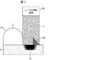
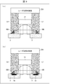
- FIG. 1 It is sectional drawing which shows the manufacturing method of the resin body bonded article in embodiment of this indication.
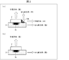
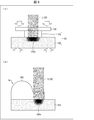
- (A) is sectional drawing which shows the effect of joining by combined use of welding and adhesion
- (b) is sectional drawing which shows the effect of joining only by welding.
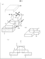
- (A) is a perspective view which shows the structure of the manufacturing apparatus for enforcing the manufacturing method of the said resin body joined article
- (b) is a perspective view which shows the structure of the resin lens 2
- (c) is a laser beam It is a front view which shows the structure of the said manufacturing apparatus except an irradiation apparatus.
- FIG. 5 is a cross-sectional view showing a state in which the resin substrate is melted, the resin lens is welded to the resin substrate, and the thermosetting adhesive is cured.
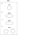
- A)-(d) is a top view which shows the shape of the irradiation area of the said laser beam.
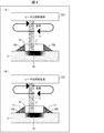
- thermosetting adhesive agent containing a laser beam absorption component (A) shows the manufacturing method of the resin body bonded article in Embodiment 3 of the present disclosure, where a laser beam is scanned and irradiated using a thermosetting adhesive not containing a laser beam absorbing component. It is sectional drawing which shows the manufacturing method of this resin body joining article, (b) of the resin body joining article in the case of scanning and irradiating a laser beam using the thermosetting adhesive containing a laser beam absorption component It is sectional drawing which shows a manufacturing method.
- FIG. 6 is a cross-sectional view showing a joining method in which a resin lens and a resin base are welded without pressing a joining surface.
- this embodiment an embodiment according to an aspect of the present disclosure (hereinafter, also referred to as “this embodiment”) will be described with reference to the drawings.
- FIG. 1 is a cross-sectional view illustrating a method for manufacturing a resin body bonded article according to an aspect of the present disclosure.
- the manufacturing method of the lens component 1 ⁇ / b> A uses a resin lens 2 that is transmissive to the laser light L and a resin base that is light-absorbing to the laser light L.
- 3 is a manufacturing method of the lens component 1A bonded to the lens 3.
- the manufacturing method of the lens component 1 ⁇ / b> A includes an overlapping process in which the resin lens 2 is overlapped with the resin base 3, and both the resin lens 2 and the resin base 3 in a region other than the overlapping surface of the resin lens 2 and the resin base 3.
- the lens component 1A has a function as a resin body bonded product of the present disclosure.
- the resin lens 2 has a function as the first resin body of the present disclosure.
- the resin base 3 has a function as the second resin body of the present disclosure.
- the resin base 3 has light absorptivity with respect to the laser light L by irradiating the resin base 3 with the laser light L through at least the resin lens 2, the surface of the resin base 3 on the first resin body side.
- the welded part 3a is melted.
- the resin lens 2 can be welded to the resin base 3.
- the adhesive in the subsequent thermal test in the case where the adhesive is present in the superposition of the resin lens 2 and the resin base 3 Misalignment due to softening can be prevented.
- thermosetting adhesive 10A that is in contact with both the resin lens 2 and the resin base 3 is applied.
- 10 A of thermosetting adhesives harden
- the resin lens 2 can be bonded to the resin base 3 with the thermosetting adhesive 10A.
- the bonding strength that is insufficient only by the welding of the resin lens 2 and the resin base 3 is compensated by the adhesion between the resin lens 2 and the resin base 3. For this reason, pressurization to the resin base 3 of the resin lens 2 for strengthening the joining strength in the direction perpendicular to the welding surface, which has been conventionally required in the joining only by welding, can be omitted.
- the lens component 1 ⁇ / b> A includes a resin lens 2 that is transmissive to the laser light L and a resin base 3 that is light-absorbable to the laser light L. It is a resin body joined product joined to.
- a compatible layer that is a welded portion 3 a is formed on the bonding side of the resin base 3 to the resin lens 2, and the resin lens 2 is formed in a region other than the resin lens 2, the resin base 3, and the bonding surface.
- a thermosetting adhesive 10 ⁇ / b> A that adheres to both the resin base 3 and the resin base 3 is provided.
- the lens component 1A that can ensure the bonding strength between the resin lens 2 and the resin base 3 even if a sufficient contact pressure cannot be ensured during the bonding.
- the method of manufacturing a resin body bonded product in the present embodiment is, for example, as a resin lens 2 as a first resin body and a second resin body when manufacturing a resin body bonded product such as a lens component of an in-vehicle optical sensor.
- This method can be applied to a method of joining with the resin base 3.
- the manufacturing method of the resin body bonded product in the present embodiment is not necessarily limited to the resin body bonded product such as the lens component of the in-vehicle optical sensor, but the product using the optical lens component such as the factory optical sensor and the robot vision. It is possible to apply to.
- the resin body bonded product is not limited to the optical lens component, and the first resin body that is non-light-absorbing and transmitting with respect to the laser light is replaced with the second resin body that is light-absorbing with respect to the laser light. It can be applied to bonded resin body bonded products.
- FIG. 1 is a cross-sectional view showing a method of manufacturing the lens component 1A in the present embodiment.
- FIG. 2A is a cross-sectional view showing the effect of joining by the combined use of welding and adhesion by the manufacturing method of the lens component 1A in the present embodiment.
- FIG. 2B is a cross-sectional view showing the effect of joining only by welding.
- the lens component 1 ⁇ / b> A as the resin body bonded product in the present embodiment is configured such that the resin lens 2 as the first resin body having transparency to the laser light L is It is joined to a resin base 3 as a second resin body having light absorption.
- the lens component 1A is formed by bonding a resin lens 2 as a first resin body and a resin base 3 as a second resin body.
- the present invention is not necessarily limited thereto, and for example, an optical prism as the first resin body may be joined to a housing as the second resin body.
- the resin lens 2 as the first resin body has a three-dimensional shape, for example, having a hemisphere on a part of a flat plate in the present embodiment.
- the resin lens 2 is not necessarily limited, and may be a lens made entirely of a flat plate, a convex lens, a concave lens, a prism, or the like.
- the resin lens 2 of the present embodiment has non-light absorption and transparency for the laser light L. For this reason, the resin lens 2 transmits the laser light L, but does not cause a phenomenon such as melting and heat generation by absorbing the laser light L.
- the 1st resin body of this indication does not necessarily need to have non-light absorption with respect to the laser beam L. FIG. This is because part of the first resin body may be melted by the first resin body having light absorptivity.
- the resin lens 2 transmits the infrared or near-infrared laser beam L, it does not necessarily have to be transparent to visible light.
- the material of the resin lens 2 is not particularly limited as long as it has thermoplasticity and has a predetermined transmittance with respect to the laser light L. Basically, the resin materials exemplified below can be used. Further, if a predetermined transmittance can be ensured, a coloring material may be mixed.
- the material of the resin lens 2 for example, PVC (polyvinyl chloride), PS (polystyrene), AS (acrylonitrile / styrene), ABS (acrylonitrile / butadiene / styrene), PMMA (polymethyl methacrylate), PE (polyethylene), PP (polypropylene), PC (polycarbonate), m-PPE (modified polyphenylene ether), PA6 (polyamide 6), PA66 (polyamide 66), POM (polyacetal), PET (polyethylene terephthalate), PBT (poly) Butylene terephthalate), PSF (polysulfone), PAR (polyarylate), PEI (polyetherimide), PPS (polyphenylene sulfide), PES (polyethersulfone), PEEK (polyetherether) Luketone), PAI (polyamideimide), LCP (liquid crystal polymer), PVDC (polyvinyl
- TPE thermoplastic elastomer
- TPE thermoplastic elastomer
- TPE thermoplastic elastomer
- examples of TPE include TPO (olefin-based), TPS (styrene-based), TPEE (ester-based), TPU (urethane-based), TPA (nylon-based), and TPVC (vinyl chloride-based).
- the resin lens 2 has, for example, a horizontal portion with a thickness of 3 mm, and is made of, for example, PC (polycarbonate).
- the resin base 3 as the second resin body is made of a material that absorbs light with respect to the laser light L.
- the resin base 3 has a thickness of 2 mm, for example, and is made of, for example, PBT (polybutylene terephthalate) mixed with carbon black.
- the material of the resin base 3 is not particularly limited as long as it has thermoplasticity and can absorb the laser light L without transmitting as a kind of the resin base 3 having a high absorption rate of the laser light L.
- the resin base 3 can be made of a resin material exemplified below mixed with carbon black or a predetermined colorant such as a dye or a pigment.
- PVC polyvinyl chloride
- PS polystyrene
- AS acrylonitrile styrene
- ABS acrylonitrile butadiene styrene
- PMMA polymethyl methacrylate
- PE polyethylene
- PP polypropylene
- PC polycarbonate
- M-PPE modified polyphenylene ether
- PA6 polyamide 6
- PA66 polyamide 66
- POM polyacetal
- PET polyethylene terephthalate
- PBT polybutylene terephthalate
- PSF polysulfone
- PAR polyarylate
- PEI polyetherimide
- PPS polyphenylene sulfide
- PES polyethersulfone
- PEEK polyetheretherketone
- PAI polyamideimide
- LCP liquid crystal polymer
- PVDC polyvinylidene chloride
- PTFE polyvinylidene chloride
- PTFE polyvinylidene chloride
- PTFE polyviny
- TPE thermoplastic elastomer
- TPO olefin type
- TPS styrene type
- TPEE esteer type
- TPU urethane type
- TPA nylon type
- TPVC vinyl chloride type
- the manufacturing method of the lens component 1 ⁇ / b> A includes a superposition process for superposing the resin lens 2 on the resin base 3, and thermosetting so as to contact both the side surface of the resin lens 2 and the upper surface of the resin base 3.
- the resin lens 2 is welded to the resin base 3 by applying a laser beam L to the resin base 3 through at least the resin lens 2 and applying the adhesive 10A. 2 is bonded to the resin base 3.
- the resin base 3 has a light absorptivity with respect to the laser light L by irradiating the resin base 3 with the laser light L through at least the resin lens 2, the resin base 3 3 of the surface 3 of the resin lens 2 is melted. Thereby, the resin base 3 side surface of the resin lens 2 is also melted, a compatible layer is formed, and the resin lens 2 can be welded to the resin base 3. As a result, since there is no adhesive at the interface between the resin lens 2 and the resin base 3, the adhesive is softened in the subsequent thermal test when the adhesive is present at the interface between the resin lens 2 and the resin base 3. Misalignment can be prevented.
- thermosetting adhesive 10 ⁇ / b> A that contacts both the side surface of the resin lens 2 and the upper surface of the resin base 3 is applied.
- 10 A of thermosetting adhesives harden
- the resin lens 2 can be bonded to the resin base 3 with the thermosetting adhesive 10A.
- the bonding strength in the direction perpendicular to the welded portion 3a is strong only by welding the resin lens 2 to the resin base 3, but in the direction parallel to the welded portion 3a. Bonding strength is small. Therefore, as shown in FIG. 2A, the resin lens 2 and the resin base 3 are bonded with a thermosetting adhesive 10 ⁇ / b> A that contacts both the side surface of the resin lens 2 and the upper surface of the resin base 3. Thus, the bonding strength in the direction parallel to the welded portion 3a can be reinforced.
- the joint strength between the resin lens 2 and the resin base 3 can be improved by using joint strength in a direction perpendicular to the interface due to welding and joint strength in a direction parallel to the interface due to adhesion.
- a shearing force is applied to the side surface of the resin lens 2 by the adhesion of the thermosetting adhesive 10A to the side surface of the resin lens 2
- a tensile force is applied in a direction parallel to the interface between the resin lens 2 and the resin base 3.
- the bonding strength in the direction parallel to the welded portion 3a can be reinforced, the resin base of the resin lens 2 for increasing the bond strength in the direction perpendicular to the welded portion 3a.
- the pressurization to 3 can be omitted.
- Laser welding refers to a method in which a laser beam L is used to heat the resin to the melting temperature and the two resins are melted together to join them.
- Laser bonding refers to a method of using the laser beam L to raise the adhesive to the curing reaction temperature and curing the adhesive.
- the present embodiment provides a method of manufacturing a lens component 1A that can ensure the bonding strength between the resin lens 2 and the resin base 3 even if a sufficient contact pressure cannot be ensured during the bonding. Can do.
- FIG. 3A is a perspective view showing the configuration of the manufacturing apparatus 20 for carrying out the manufacturing method of the lens component 1A.
- FIG. 3B is a perspective view showing the configuration of the resin lens 2.
- FIG. 3C is a front view showing the configuration of the manufacturing apparatus 20 excluding the laser beam irradiation apparatus 22A.
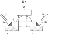
- FIG. 4 is a front view showing a state in which the thermosetting adhesive 10 ⁇ / b> A is applied by the adhesive application nozzle 23 of the manufacturing apparatus 20.
- FIG. 3A is a perspective view showing the configuration of the manufacturing apparatus 20 for carrying out the manufacturing method of the lens component 1A.
- FIG. 3B is a perspective view showing the configuration of the resin lens 2.
- FIG. 3C is a front view showing the configuration of the manufacturing apparatus 20 excluding the laser beam irradiation apparatus 22A.
- FIG. 4 is a front view showing a state in which the thermosetting adhesive 10 ⁇ / b> A is applied by the adhesive application nozzle 23 of the manufacturing apparatus 20.
- FIG. 5A is a cross-sectional view showing a state in which the resin lens 2 and the thermosetting adhesive 10 ⁇ / b> A are simultaneously passed by the laser beam L and irradiated onto the resin base 3 in the manufacturing apparatus 20.
- FIG. 5B shows that the resin base 3 is irradiated with the laser beam L to melt the welded portion 3a of the resin base 3 so that the resin lens 2 is welded to the resin base 3, and the thermosetting adhesive 10A is applied.
- 6A to 6D are plan views showing the shape of the irradiation region of the laser light L.
- the manufacturing apparatus 20 for the lens component 1 ⁇ / b> A of the present embodiment is for adjusting the position of the resin lens 2 on the resin base 3.
- a position adjusting chuck 21, a laser beam irradiation device 22 ⁇ / b> A for irradiating the laser beam L, and an adhesive application nozzle 23 are provided.
- the position adjusting chuck 21 has gripping portions 21a and 21a.
- the gripping portions 21a and 21a are for gripping the resin lens 2 shown in FIG.
- the protrusion 2a is clamped.
- the position adjusting chuck 21 horizontally moves the resin lens 2 in a planar manner in a state where the resin lens 2 is lightly pressed on the resin base 3 while holding the resin lens 2 with the gripping portions 21a and 21a.
- the position is adjusted so that the desired position is obtained while checking the optical characteristics.
- the laser beam irradiation device 22A is a device that irradiates the laser beam L.
- infrared light having a wavelength of 808 nm is emitted.
- the laser output can be irradiated at 3 W for 15 seconds, for example.
- the laser light L emitted from the laser light irradiation device 22A is simultaneously passed through the resin lens 2 and the thermosetting adhesive 10A.
- the resin base 3 is irradiated.
- the laser light L is emitted from, for example, two locations of the laser light irradiation device 22A so that the respective side surfaces can be irradiated simultaneously. Note that the number is not limited to two and may be two.
- the melting temperature at the weld portion 3a of the resin base 3 becomes 250 ° C.
- the shape of the irradiation region of the laser beam L of the present embodiment is, for example, a circle as shown in FIG. This shape is formed, for example, by narrowing down with a lens (not shown).
- the shape of the irradiation region of the laser beam L is not necessarily circular, and for example, the resin lens 2 and the thermosetting adhesive 10 ⁇ / b> A can be irradiated simultaneously and irradiated, for example, (b) and (c) of FIG.
- the shape may be an ellipse, a polygon including a triangle, or a quadrangle.
- the shape of the irradiation region of the laser light L can be set to an irradiation region of a desired shape by using, for example, a mask having the opening having the above shape.
- the manufacturing apparatus 20 for the lens component 1A includes two adhesive application nozzles 23 that apply the thermosetting adhesive 10A to both side surfaces of the resin lens 2. Yes.
- the adhesive application nozzle 23 of this embodiment applies the thermosetting adhesive 10 ⁇ / b> A obliquely to both side surfaces of the resin lens 2. Thereby, it becomes easy to apply the thermosetting adhesive 10 ⁇ / b> A to both the side surface of the resin lens 2 and the upper surface of the resin base 3.
- the thermosetting adhesive 10 ⁇ / b> A is applied to both side surfaces of the resin lens 2.
- the present invention is not limited to this, and it is possible to apply only to one side surface of the resin lens 2. This is because, depending on the shape of the resin lens 2 and the resin base 3, it may be sufficient to apply only to one side surface of the resin lens 2.
- thermosetting adhesive 10A is made of, for example, an epoxy resin (EP) in the present embodiment.
- the thermosetting adhesive 10A of the present embodiment includes, for example, 100 parts by mass of a bisphenol A type epoxy resin, 5 parts by mass of an epoxy resin imidazole adduct compound, 20 parts by mass of a capsule type curing agent, and It consists of an adhesive composition in which 20 parts by mass of silica is blended.
- thermosetting adhesive 10A of the present embodiment is adapted to be cured by absorbing the heat generated when the laser beam L is irradiated onto the resin base 3 to melt the welded portion 3a. Specifically, the thermosetting adhesive 10A is cured by holding the reaction at, for example, 130 ° C. for 15 seconds to advance the reaction. As a result, in the present embodiment, by using the thermosetting adhesive 10A, it is possible to join with high heat resistance.
- thermosetting adhesive 10A is not limited to the above-described epoxy resin (EP), and is not particularly limited as long as it is a resin that is cured by reacting with the curing agent by heat. Further, the curing agent contained in the thermosetting adhesive 10A is not particularly limited as long as it is a curing agent that reacts with the resin by heat and cures. However, from the viewpoint of curing the epoxy resin at a low temperature in a short time, it is preferable to include at least one compound selected from the group consisting of amine compounds, imidazole compounds, and thiol compounds, for example. Further, from the viewpoint of controlling the curing reaction by heat of the thermosetting adhesive 10 ⁇ / b> A, it is preferable to use a capsule-type curing agent including the above-described core containing the curing agent and a shell covering the core.
- the resin lens 2 as the first resin body having transparency to the laser light L is applied to the laser light L.
- the resin lens 2 is superposed on the resin base 3 and the resin lens 2 and the resin base 3 are brought into contact with each other in a region other than the superposed surface of the resin lens 2 and the resin base 3.
- the resin lens 2 is welded to the resin base 3 by irradiating the resin base 3 with the laser beam L through at least the application step of applying the thermosetting adhesive 10A and the resin lens 2, and the thermosetting adhesive.
- the resin lens 2 can be welded to the resin base 3.
- the adhesive in the subsequent thermal test when the adhesive is present at the interface between the resin lens 2 and the resin base 3 Misalignment due to softening of the agent can be prevented.
- thermosetting adhesive 10A is cured by the conduction of heat when the resin base 3 melts, the resin lens 2 is bonded to the resin base 3 with the thermosetting adhesive 10A. Can be made.
- the bonding strength that is insufficient only by welding the resin lens 2 and the resin base 3 is compensated for by bonding the resin lens 2 and the resin base 3.
- pressurization to the resin base 3 of the resin lens 2 for strengthening the joining strength in the direction perpendicular to the welding surface, which has been conventionally required in the joining only by welding can be omitted.
- the bonding between the resin lens 2 and the resin base 3 can be achieved by combining the welding strength and the adhesive strength. Sufficient strength can be secured.
- thermosetting adhesive 10 ⁇ / b> A is applied so as to be in contact with both the upper surface of the resin base 3 parallel to the interface with the base 3.
- the thermosetting adhesive 10 ⁇ / b> A does not need to be in contact with both side surfaces of the resin lens 2, and may be in contact with only one side surface of the resin lens 2.
- the side surface of the resin lens 2 does not have to be strictly orthogonal (90 degrees) to the interface between the resin lens 2 and the resin base 3, as long as the angle is sufficient to ensure the adhesive strength. For example, it may be about 45 to 135 degrees. That is, the angle of intersection with the side surface of the resin lens 2 with respect to the interface is most preferably 90 degrees in terms of strength, but the angle of intersection cannot be set to 90 degrees due to structural limitations of the resin lens 2 and the resin base 3. There is also a possibility. In addition, the relationship between the upper surface of the resin base 3 and the interface may not be strictly parallel due to structural limitations of the resin lens 2 and the resin base 3.
- thermosetting adhesive 10 ⁇ / b> A that contacts both the side surface of the resin lens 2 and the upper surface of the resin base 3, the bonding strength parallel to the welding surface is obtained. Can be reinforced.
- the bonding strength parallel to the weld surface is obtained by bonding the resin lens 2 and the resin base 3 with the thermosetting adhesive 10A that contacts both the side surface of the resin lens 2 and the upper surface of the resin base 3.
- the joint strength between the resin lens 2 and the resin base 3 is obtained by using joint strength, that is, tensile strength by welding in a direction perpendicular to the overlapping surface, and joint strength, that is, shear strength, by adhesion in a direction parallel to the overlapping surface. Can be improved.
- the manufacturing method of the lens component 1A in the present embodiment it is possible to irradiate the resin base 3 by simultaneously passing the laser light L through the resin lens 2 and the thermosetting adhesive 10A in the bonding step. .
- thermosetting adhesive 10A welding of the resin lens 2 and the resin base 3 and adhesion to the resin lens 2 and the resin base 3 by the thermosetting adhesive 10A are simultaneously performed.
- the resin base 3 immediately below the thermosetting adhesive 10A is also rapidly heated by the laser beam L, the thermosetting of the thermosetting adhesive 10A is promoted, and the resin lens 2 is quickly fixed to the resin base 3. can do.
- thermosetting adhesive 10A since a separate curing furnace for curing the thermosetting adhesive 10A is provided and the thermosetting adhesive 10A is not bonded in a separate process, the tact time is shortened and the equipment cost is increased. Can be prevented. As a result, productivity increases, and an accurate and highly reliable optical sensor can be realized.
- the irradiation can be performed with the laser light L having any one of the circular, elliptical, and polygonal irradiation regions.
- the irradiation area of the laser beam L is generally circular, an elliptical or polygonal irradiation area is formed in accordance with the shape of the irradiation area obtained by combining the resin lens 2 and the thermosetting adhesive 10A. It becomes possible. Further, the expansion of the heating range with the laser beam L increases the welding area, and the bonding strength can be increased.
- the lens component 1 ⁇ / b> A in the present embodiment is obtained by joining a resin lens 2 that is transmissive to the laser light L to a resin base 3 that is light-absorbing to the laser light L.
- the lens component 1 ⁇ / b> A has a compatible layer as a welded portion 3 a formed on the bonding side of the resin base 3 to the resin lens 2, and in a region other than the bonding surface between the resin lens 2 and the resin base 3.
- a thermosetting adhesive 10 ⁇ / b> A that adheres to both the resin lens 2 and the resin base 3 is provided.
- the lens component 1A that can ensure the bonding strength between the resin lens 2 and the resin base 3 even if a sufficient contact pressure cannot be ensured during the bonding.
- the first resin body is the resin lens 2
- the second resin body is the resin base 3 as a resin substrate. Accordingly, it is possible to provide the lens component 1 ⁇ / b> A as a resin body bonded product that can ensure the bonding strength between the resin lens 2 and the resin base 3 even if a sufficient contact pressure cannot be ensured at the time of bonding.
- the manufacturing method of the lens component 1B as the resin body bonded product of the present embodiment includes the laser light absorbing component 11 in the thermosetting adhesive 10B. It is different in that it is mixed.
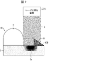
- FIG. 7 shows a method for manufacturing the lens component 1B in the present embodiment, and is a cross-sectional view showing a method for manufacturing the lens component 1B using the thermosetting adhesive 10B containing the laser light absorbing component 11. is there.
- the laser light absorbing component 11 is mixed in the thermosetting adhesive 10B.
- the laser light absorbing component 11 is made of, for example, carbon black.
- the present invention is not necessarily limited to this, and a mixture of a predetermined colorant such as a dye or pigment may be used.
- a resin such as an epoxy resin can be used as in the thermosetting adhesive 10A of the first embodiment.
- thermosetting adhesive 10B containing the laser light absorbing component 11 is used in the joining step.
- the temperature of the thermosetting adhesive 10B is increased by the laser beam absorbing component 11, and the thermosetting adhesive 10B is thermoset. Adhesive function is exhibited. That is, the thermosetting adhesive 10B is cured by the heat generated by the thermosetting adhesive 10B itself.
- thermosetting adhesive 10 ⁇ / b> B itself that has absorbed the laser light L can be thermally cured to exhibit an adhesive function without relying on the heat at the time of melting of the resin base 3 due to the laser light L irradiation. That is, the heat load on the resin base 3 is reduced.
- thermosetting adhesive 10B the welding of the resin lens 2 and the resin base 3 and the adhesion to the resin lens 2 and the resin base 3 by the thermosetting adhesive 10B are simultaneously performed. As a result, it is possible to prevent the occurrence of displacement due to the generation of unnecessary stress based on the displacement of the bonding time between the resin lens 2 and the resin base 3. In addition, the tact time can be shortened.
- the manufacturing method of the lens component 1C as the resin body bonded product of the present embodiment includes a laser in addition to the configuration of the manufacturing method of the lens component 1A of the first embodiment and the manufacturing method of the lens component 1B of the second embodiment.
- the light irradiation device 22C is different in that the resin base 3 is irradiated with the laser beam L1 scanned.
- FIG. 8A shows a manufacturing method of the lens component 1 ⁇ / b> C in the present embodiment, which uses a thermosetting adhesive 10 ⁇ / b> A of the resin lens 2 that does not contain the laser light absorbing component 11, and laser light. It is sectional drawing which shows the case where L1 is scanned and irradiated.
- FIG. 8B is a cross-sectional view showing a case where the laser light L1 is scanned and irradiated using the thermosetting adhesive 10B containing the laser light absorbing component 11 shown in the second embodiment.
- the laser beam irradiation device 22C scans the laser beam L1 and irradiates the resin base 3.
- the laser beam L1 is first passed through only the resin lens 2 and irradiated to the resin base 3, and then the laser beam L1 is irradiated only to the thermosetting adhesive 10A.
- the resin base 3 can be irradiated through. That is, if the thermosetting adhesive 10 ⁇ / b> A is cured first, the position of the resin lens 2 with respect to the resin base 3 may be shifted with shrinkage during curing.
- the resin lens 2 is first welded to the resin base 3, and then the thermosetting adhesive 10A is irradiated with the laser light L1 and thermally cured.
- the adhesive 10A can be cured. As a result, it is possible to prevent displacement of the resin lens 2 with respect to the resin base 3.
- the resin base 3 by irradiating the resin base 3 by scanning the laser beam L1, it is not necessary to make one irradiation area of the laser beam L1 the area of the resin lens 2. Thereby, the shape of one irradiation area
- the manufacturing method of the lens component 1 ⁇ / b> C using the thermosetting adhesive 10 ⁇ / b> A that does not contain the laser light absorption component 11 of Embodiment 1 has been described.
- the present invention is not necessarily limited to this, and as shown in FIG. 8B, a thermosetting adhesive containing the laser light absorbing component 11 of the second embodiment. The same method can be applied to the manufacturing method of the lens component 1C using 10B, and the same effect can be obtained.
- a method for manufacturing a resin body bonded article has a first resin body that is transmissive to laser light and a light absorption property to the laser light.
- the superposing step of superposing the first resin body on the second resin body, and the superposition of the first resin body and the second resin body An application step of applying a thermosetting adhesive so as to come into contact with both the first resin body and the second resin body in a region other than the surface; and through the at least first resin body, the second resin body A bonding step of welding the first resin body to the second resin body by irradiating laser light, and bonding the first resin body to the second resin body with the thermosetting adhesive; It is characterized by including. “At least through the first resin body” means “through at least the first resin body of the first resin body and the thermosetting adhesive”.
- the second resin body since the second resin body has a light absorption property to the laser light by irradiating the second resin body with laser light through at least the first resin body, the first resin of the second resin body.
- the body side surface melts.
- a 1st resin body can be welded to a 2nd resin body.
- the subsequent heat when the adhesive is present on the overlapping of the first resin body and the second resin body since there is no adhesive on the overlapping surface of the first resin body and the second resin body, the subsequent heat when the adhesive is present on the overlapping of the first resin body and the second resin body. Misalignment due to softening of the adhesive in the test can be prevented.
- thermosetting adhesive that contacts both the first resin body and the second resin body is applied when the first resin body is welded to the second resin body. For this reason, the thermosetting adhesive is cured by the heat generated when the first resin body-side surface is melted. As a result, the first resin body can be bonded to the second resin body with a thermosetting adhesive.
- the bonding strength that is insufficient only by welding between the first resin body and the second resin body is compensated for by adhesion between the first resin body and the second resin body.
- vertical to a welding surface which was conventionally required in joining only by welding can be abbreviate
- thermosetting adhesive in the application step, can be applied so as to be in contact with both the upper surface of the second resin body parallel to the overlapping surface of the first resin body and the second resin body.
- the thermosetting adhesive need not be in contact with both side surfaces of the first resin body, and may be in contact with only one side surface of the first resin body.
- first resin body and the second resin body are adhered to each other with a thermosetting adhesive that contacts both the side surface of the first resin body and the upper surface of the second resin body, thereby being parallel to the welding surface.
- the joint strength can be reinforced.
- the bonding strength in the direction perpendicular to the welding surface is strong, but the bonding strength in the direction parallel to the welding surface is small. Therefore, by bonding the first resin body and the second resin body with a thermosetting adhesive that contacts both the side surface of the first resin body and the upper surface of the second resin body, it is parallel to the welding surface.
- the joint strength can be reinforced. That is, the joint strength between the first resin body and the second resin body can be improved by using the joint strength by welding in the direction perpendicular to the overlapping surface and the joint strength by bonding in the direction parallel to the overlapping surface. Can do.
- thermosetting adhesive containing a laser light absorbing component in the bonding step.
- thermosetting adhesive itself contains a laser light absorbing component
- the temperature of the thermosetting adhesive rises due to the laser light absorbing component
- thermosetting adhesive exhibits an adhesive function by thermosetting.
- thermosetting adhesive can be thermally cured by the laser beam and exhibit an adhesive function without relying on heat due to welding.
- the laser light is simultaneously passed through the first resin body and the thermosetting adhesive to irradiate the second resin body. Then you can do it.
- the laser light is irradiated to the second resin body through both the first resin body and the thermosetting adhesive, so that the first resin body and the second resin body are welded and the first resin body and the thermosetting adhesive are used. Bonding to the first resin body and the second resin body is performed simultaneously.
- the tact time can be shortened.
- the laser light in the bonding step, can be scanned and irradiated to the second resin body.
- the second resin body can be irradiated through only the thermosetting adhesive. That is, if the thermosetting adhesive is cured first, a positional shift of the first resin body with respect to the second resin body due to shrinkage during curing can be considered. However, in the irradiation method by scanning, since the thermosetting adhesive can be cured after the first resin body is first welded to the second resin body, the first resin body is misaligned with respect to the second resin body. Can be prevented.
- the bonding step may be performed by irradiation with the laser beam having a circular, elliptical, or polygonal irradiation region.
- the irradiation area of the laser beam is generally circular, but according to the shape of the irradiation area combining the first resin body and the thermosetting adhesive, an elliptical or polygonal irradiation area and It becomes possible to do.
- the resin body bonded product according to an aspect of the present disclosure is a resin body bonded product in which a first resin body that is transparent to laser light is bonded to a second resin body that is light absorbing to the laser light.
- a compatible layer is formed on the bonding side of the second resin body to the first resin body, and the first resin body is formed in a region other than the bonding surface between the first resin body and the second resin body.
- a thermosetting adhesive that adheres to both the resin body and the second resin body is provided.
- a compatible layer that is a welded portion is formed as a trace shape on the bonding side of the second resin body to the first resin body. be able to.
- the first resin body may be a resin lens
- the second resin body may be a resin substrate
Landscapes
- Engineering & Computer Science (AREA)
- Mechanical Engineering (AREA)
- Physics & Mathematics (AREA)
- Optics & Photonics (AREA)
- Health & Medical Sciences (AREA)
- Electromagnetism (AREA)
- Toxicology (AREA)
- Lining Or Joining Of Plastics Or The Like (AREA)
Abstract
レンズ部品(1A)の製造方法は、レーザ光(L)に対して透過性を有する樹脂レンズ(2)を、レーザ光(L)に対して光吸収性を有する樹脂ベース(3)に接合する。樹脂レンズ(2)を樹脂ベース(3)に重ね合わせる重ね合わせ工程と、樹脂レンズ(2)と樹脂ベース(3)との重ね合わせ面以外の領域で両方に接触するように熱硬化性接着剤(10A)を塗布する塗布工程と、少なくとも樹脂レンズ(2)を通して樹脂ベース(3)にレーザ光(L)を照射することにより、樹脂レンズ(2)を樹脂ベース(3)に溶着させると共に、熱硬化性接着剤(10A)にて樹脂レンズ(2)を樹脂ベース(3)に接着させる接合工程とを含む。
Description
本開示は、第1樹脂体を第2樹脂体に接合した樹脂体接合品の製造方法及び樹脂体接合品に関するものである。
従来、樹脂レンズを樹脂ベースに接合してなる樹脂体接合品であるレンズ部品を製造する場合には、組立ラインの中で樹脂レンズを保持しながら光学特性検査を実施し、最も特性の良い位置で樹脂レンズを樹脂ベースに固定してレンズ部品を製造していた。
例えば特許文献1では、光学プリズムをハウジングに接合する場合に、光学プリズムとハウジングとの界面にアクリル系紫外線硬化樹脂を用いていた。
また、例えば特許文献2では、レーザ光を照射して樹脂レンズを樹脂ベースに溶着させていた。その際、特許文献2では、図9の(a)に示すように、必要な接合強度を確保すべく、樹脂レンズ102と樹脂ベース103との接触圧を上げるために、レーザ光120を透過するガラス板130で樹脂レンズ102を押圧しながら、レーザ光120を照射していた。これにより、レーザ吸収成分含有の樹脂ベース103を溶着部103aにて溶融して、樹脂レンズ102を樹脂ベース103に溶着させて、レンズ部品101を製造していた。
しかしながら、前記従来の特許文献1の接合方法では、接合界面に耐熱温度が低いアクリル系紫外線硬化樹脂を使用しているので、熱衝撃試験等の熱試験においてアクリル系紫外線硬化樹脂が軟化する。この結果、光学プリズムがハウジングに対して位置ズレを起したり、アクリル系紫外線硬化樹脂にクラックが発生したりすることによって、光学プリズムをハウジングに対して精密位置固定することができなかった。そのため、光学部品の光学仕様を大幅に緩和せざるを得なくなるという問題、つまり光学部品の高品質を維持できないという問題があった。
また、前記従来の特許文献2の接合方法では、必要な接合強度を確保するために、接合圧力を高めているので、接合面を押し付けるガラス板等のスペースが必要となるという問題を有している。例えば、図9の(b)に示すように、樹脂レンズ102が立体形状からなりかつ溶融できる面積が小さい場合には、前記ガラス板130を用いて接合面を押圧することができない。このため、樹脂レンズ102と樹脂ベース103との界面の接触圧が十分に確保できない。その結果、樹脂レンズ102と樹脂ベース103との接合強度が十分に確保することができないという問題点を有している。
本開示の一態様は、前記従来の問題点に鑑みなされたものであって、その目的は、接合時に十分な接触圧が確保できなくても、第1樹脂体と第2樹脂体との接合強度を確保し得る樹脂体接合品の製造方法及び樹脂体接合品を提供することにある。
本開示の一態様における樹脂体接合品の製造方法は、上記の課題を解決するために、レーザ光に対して透過性を有する第1樹脂体を、前記レーザ光に対して光吸収性を有する第2樹脂体に接合した樹脂体接合品の製造方法において、前記第1樹脂体を前記第2樹脂体に重ね合わせる重ね合わせ工程と、前記第1樹脂体と前記第2樹脂体との重ね合わせ面以外の領域で該第1樹脂体と該第2樹脂体との両方に接触するように熱硬化性接着剤を塗布する塗布工程と、少なくとも前記第1樹脂体を通して前記第2樹脂体に前記レーザ光を照射することにより、前記第1樹脂体を前記第2樹脂体に溶着させると共に、前記熱硬化性接着剤にて前記第1樹脂体を前記第2樹脂体に接着させる接合工程とを含むことを特徴としている。尚、「少なくとも第1樹脂体を通して」とは、「第1樹脂体及び熱硬化性接着剤のうちの少なくとも第1樹脂体を通して」の意味である。
本開示の一態様における樹脂体接合品は、レーザ光に対して透過性を有する第1樹脂体を、前記レーザ光に対して光吸収性を有する第2樹脂体に接合した樹脂体接合品において、前記第2樹脂体の前記第1樹脂体への接合側には相溶層が形成されていると共に、前記第1樹脂体と前記第2樹脂体との接合面以外の領域で該第1樹脂体と該第2樹脂体との両方に接着する熱硬化性接着剤が設けられていることを特徴としている。
本開示の一態様によれば、接合時に十分な接触圧が確保できなくても、第1樹脂体と第2樹脂体との接合強度を確保し得る樹脂体接合品の製造方法及び樹脂体接合品を提供するという効果を奏する。
以下、本開示の一側面に係る実施の形態(以下、「本実施形態」とも表記する)を、図面に基づいて説明する。
(適用例)
まず、図1に基づいて、本開示が適用される場面の一例について説明する。図1は、本開示の一態様における樹脂体接合品の製造方法を示す断面図である。
まず、図1に基づいて、本開示が適用される場面の一例について説明する。図1は、本開示の一態様における樹脂体接合品の製造方法を示す断面図である。
図1に示すように、本開示の実施の形態におけるレンズ部品1Aの製造方法は、レーザ光Lに対して透過性を有する樹脂レンズ2を、レーザ光Lに対して光吸収性を有する樹脂ベース3に接合したレンズ部品1Aの製造方法である。レンズ部品1Aの製造方法は、樹脂レンズ2を樹脂ベース3に重ね合わせる重ね合わせ工程と、樹脂レンズ2と樹脂ベース3との重ね合わせ面以外の領域で樹脂レンズ2と樹脂ベース3との両方に接触するように熱硬化性接着剤10Aを塗布する塗布工程と、少なくとも樹脂レンズ2を通して樹脂ベース3にレーザ光Lを照射することにより、樹脂レンズ2を樹脂ベース3に溶着させると共に、熱硬化性接着剤10Aにて樹脂レンズ2を樹脂ベース3に接着させる接合工程とを含む。尚、レンズ部品1Aは本開示の樹脂体接合品としての機能を有している。樹脂レンズ2は、本開示の第1樹脂体としての機能を有している。樹脂ベース3は、本開示の第2樹脂体としての機能を有している。
前記方法によれば、少なくとも樹脂レンズ2を通して樹脂ベース3にレーザ光Lを照射することにより、樹脂ベース3がレーザ光Lに対して光吸収性を有するので、樹脂ベース3の第1樹脂体側表面である溶着部3aが溶融する。これにより、樹脂レンズ2を樹脂ベース3に溶着させることができる。この結果、樹脂レンズ2と樹脂ベース3との重ね合わせに接着剤が存在しないので、樹脂レンズ2と樹脂ベース3との重ね合わせに接着剤が存在した場合の、その後の熱試験における接着剤の軟化による位置ずれを防止することができる。
また、本開示の一態様においては、樹脂レンズ2の樹脂ベース3への溶着に際して、樹脂レンズ2と樹脂ベース3との両方に接触する熱硬化性接着剤10Aが塗布されている。このため、溶着部3aが溶融するときの熱によって、熱硬化性接着剤10Aが硬化する。この結果、熱硬化性接着剤10Aにて樹脂レンズ2を樹脂ベース3に接着させることができる。
ここで、本開示の一態様における接合方法では、樹脂レンズ2と樹脂ベース3との溶着のみでは不十分な接合強度を、樹脂レンズ2と樹脂ベース3との接着によって補っている。このため、溶着のみの接合において従来必要であった、溶着面に垂直な方向への接合強度を強めるための樹脂レンズ2の樹脂ベース3への加圧を省略することができる。
したがって、接合時に十分な接触圧が確保できなくても、樹脂レンズ2と樹脂ベース3との接合強度を確保し得るレンズ部品1Aの製造方法を提供することができる。
また、図1に示すように、本開示の実施の形態におけるレンズ部品1Aは、レーザ光Lに対して透過性を有する樹脂レンズ2を、レーザ光Lに対して光吸収性を有する樹脂ベース3に接合した樹脂体接合品である。レンズ部品1Aは、樹脂ベース3の樹脂レンズ2への接合側には溶着部3aである相溶層が形成されていると共に、樹脂レンズ2と樹脂ベース3と接合面以外の領域で樹脂レンズ2と樹脂ベース3とのとの両方に接着する熱硬化性接着剤10Aが設けられている。
これにより、接合時に十分な接触圧が確保できなくても、樹脂レンズ2と樹脂ベース3との接合強度を確保し得るレンズ部品1Aを提供することができる。
(構成例)
〔実施の形態1〕
本開示の実施の形態について図1~図6に基づいて説明すれば、以下のとおりである。
〔実施の形態1〕
本開示の実施の形態について図1~図6に基づいて説明すれば、以下のとおりである。
本実施の形態における樹脂体接合品の製造方法は、例えば、車載向け光学センサのレンズ部品等の樹脂体接合品を製造する場合の、第1樹脂体としての樹脂レンズ2と第2樹脂体としての樹脂ベース3との接合方法に適用することができる。ただし、本実施の形態における樹脂体接合品の製造方法は、必ずしも車載向け光学センサのレンズ部品等の樹脂体接合品に限らず、工場向け光学センサ、ロボットビジョン等の光学レンズ部品を使用する商品に適用することが可能である。さらに、樹脂体接合品は、光学レンズ部品に限らず、レーザ光に対して非光吸収性かつ透過性を有する第1樹脂体を、レーザ光に対して光吸収性を有する第2樹脂体に接合した樹脂体接合品に適用が可能である。
(レンズ部品の構成)
本実施の形態における樹脂体接合品としてのレンズ部品1Aの構成について、図1及び図2の(a)(b)に基づいて説明する。図1は、本実施の形態におけるレンズ部品1Aの製造方法を示す断面図である。図2の(a)は、本実施の形態におけるレンズ部品1Aの製造方法による溶着と接着との併用による接合の効果を示す断面図である。図2の(b)は、溶着のみによる接合の効果を示す断面図である。
本実施の形態における樹脂体接合品としてのレンズ部品1Aの構成について、図1及び図2の(a)(b)に基づいて説明する。図1は、本実施の形態におけるレンズ部品1Aの製造方法を示す断面図である。図2の(a)は、本実施の形態におけるレンズ部品1Aの製造方法による溶着と接着との併用による接合の効果を示す断面図である。図2の(b)は、溶着のみによる接合の効果を示す断面図である。
図1に示すように、本実施の形態における樹脂体接合品としてのレンズ部品1Aは、レーザ光Lに対して透過性を有する第1樹脂体としての樹脂レンズ2を、レーザ光Lに対して光吸収性を有する第2樹脂体としての樹脂ベース3に接合したものである。
レンズ部品1Aは、本実施の形態では、第1樹脂体としての樹脂レンズ2と第2樹脂体としての樹脂ベース3とを接合してなっている。ただし、必ずしもこれに限らず、例えば、第1樹脂体としての光学プリズムを第2樹脂体としてのハウジングに接合したものであってもよい。
前記第1樹脂体としての樹脂レンズ2は、図1に示すように、本実施の形態では、例えば、平板の一部に半球体を有して立体形状にてなっている。ただし、必ずしも限らず、樹脂レンズ2は、全体的に平板からなるレンズや、凸レンズ、凹レンズ、プリズム等であってもよい。
本実施の形態の樹脂レンズ2は、レーザ光Lに対して非光吸収性かつ透過性を有している。このため、樹脂レンズ2は、レーザ光Lを透過させるが該レーザ光Lを吸収することにより溶融して発熱する等の現象は起こらない。尚、本開示の第1樹脂体は、レーザ光Lに対して必ずしも非光吸収性を有していなくてもよい。第1樹脂体が光吸収性を有することにより、第1樹脂体の一部が溶融してもよいためである。
また、樹脂レンズ2は赤外線や近赤外線のレーザ光Lに対して透過するので、必ずしも可視光に対して透明でなくてもよい。
樹脂レンズ2の材質としては、熱可塑性を有し、レーザ光Lに対して所定の透過率を有するものであれば特に限定されない。基本的に以下に例示した樹脂材が使用可能である。また、所定の透過率を確保できれば、着色材を混入してもよい。
具体的には、樹脂レンズ2の材質としては、例えば、PVC(ポリ塩化ビニル)、PS(ポリスチレン)、AS(アクリロニトリル・スチレン)、ABS(アクリロニトリル・ブタジエン・スチレン)、PMMA(ポリメチルメタクリレート)、PE(ポリエチレン)、PP(ポリプロピレン)、PC(ポリカーボネート)、m-PPE(変性ポリフェニレンエーテル)、PA6(ポリアミド6)、PA66(ポリアミド66)、POM(ポリアセタール)、PET(ポリエチレンテレフタレート)、PBT(ポリブチレンテレフタレート)、PSF(ポリサルホン)、PAR(ポリアリレート)、PEI(ポリエーテルイミド)、PPS(ポリフェニレンサルファイド)、PES(ポリエーテルサルホン)、PEEK(ポリエーテルエーテルケトン)、PAI(ポリアミドイミド)、LCP(液晶ポリマー)、PVDC(ポリ塩化ビニリデン)、PTFE(ポリテトラフルオロエチレン)、PCTFE(ポリクロロトリフルオロエチレン)、及びPVDF(ポリフッ化ビニリデン)を使用することができる。また、TPE(熱可塑性エラストマ)であってもよい。TPEの一例としては、例えば、TPO(オレフィン系)、TPS(スチレン系)、TPEE(エステル系)、TPU(ウレタン系)、TPA(ナイロン系)、及びTPVC(塩化ビニル系)が挙げられる。
本実施の形態では、樹脂レンズ2は、例えば、水平部の厚さ3mmであり、例えばPC(ポリカーボネート)からなっている。
第2樹脂体としての樹脂ベース3は、レーザ光Lに対して光吸収性を有する材料からなっている。具体的には、樹脂ベース3は、例えば、厚さ2mmであり、例えば、PBT(ポリブチレンテレフタレート)にカーボンブラックを混入したものからなっている。
尚、樹脂ベース3の材質は、レーザ光Lの吸収率の高い樹脂ベース3の種類として、熱可塑性を有し、レーザ光Lを透過せずに吸収し得るものであれば特に限定されない。例えば、樹脂ベース3の材質として、以下に例示した樹脂材料に、カーボンブラック、又は染料や顔料等の所定の着色材を混入したもので構成することが可能である。
例えば、PVC(ポリ塩化ビニル)、PS(ポリスチレン)、AS(アクリロニトリル・スチレン)、ABS(アクリロニトリル・ブタジエン・スチレン)、PMMA(ポリメチルメタクリレート)、PE(ポリエチレン)、PP(ポリプロピレン)、PC(ポリカーボネート)、m-PPE(変性ポリフェニレンエーテル)、PA6(ポリアミド6)、PA66(ポリアミド66)、POM(ポリアセタール)、PET(ポリエチレンテレフタレート)、PBT(ポリブチレンテレフタレート)、PSF(ポリサルホン)、PAR(ポリアリレート)、PEI(ポリエーテルイミド)、PPS(ポリフェニレンサルファイド)、PES(ポリエーテルサルホン)、PEEK(ポリエーテルエーテルケトン)、PAI(ポリアミドイミド)、LCP(液晶ポリマー)、PVDC(ポリ塩化ビニリデン)、PTFE(ポリテトラフルオロエチレン)、PCTFE(ポリクロロトリフルオロエチレン)、及びPVDF(ポリフッ化ビニリデン)である。
また、TPE(熱可塑性エラストマ)であってもよい。TPEの一例としては、TPO(オレフィン系)、TPS(スチレン系)、TPEE(エステル系)、TPU(ウレタン系)、TPA(ナイロン系)、及びTPVC(塩化ビニル系)を使用することができる。
(レンズ部品の製造方法)
前記構成を備えたレンズ部品1Aの製造方法について説明する。本実施の形態のレンズ部品1Aの製造方法は、樹脂レンズ2を樹脂ベース3に重ね合わせる重ね合わせ工程と、樹脂レンズ2の側面と樹脂ベース3の上面との両方に接触するように熱硬化性接着剤10Aを塗布する塗布工程と、少なくとも樹脂レンズ2を通して樹脂ベース3にレーザ光Lを照射することにより、樹脂レンズ2を樹脂ベース3に溶着させると共に、熱硬化性接着剤10Aにて樹脂レンズ2を樹脂ベース3に接着させる接合工程とを含む。
前記構成を備えたレンズ部品1Aの製造方法について説明する。本実施の形態のレンズ部品1Aの製造方法は、樹脂レンズ2を樹脂ベース3に重ね合わせる重ね合わせ工程と、樹脂レンズ2の側面と樹脂ベース3の上面との両方に接触するように熱硬化性接着剤10Aを塗布する塗布工程と、少なくとも樹脂レンズ2を通して樹脂ベース3にレーザ光Lを照射することにより、樹脂レンズ2を樹脂ベース3に溶着させると共に、熱硬化性接着剤10Aにて樹脂レンズ2を樹脂ベース3に接着させる接合工程とを含む。
本実施の形態のレンズ部品1Aの製造方法では、少なくとも樹脂レンズ2を通して樹脂ベース3にレーザ光Lを照射することにより、樹脂ベース3がレーザ光Lに対して光吸収性を有するので、樹脂ベース3の樹脂レンズ2側表面の溶着部3aが溶融する。これにより、樹脂レンズ2の樹脂ベース3側表面も溶融し、相溶層が形成され、樹脂レンズ2を樹脂ベース3に溶着させることができる。この結果、樹脂レンズ2と樹脂ベース3との界面に接着剤が存在しないので、樹脂レンズ2と樹脂ベース3との界面に接着剤が存在した場合の、その後の熱試験における接着剤の軟化による位置ずれを防止することができる。
また、本実施の形態においては、樹脂レンズ2の樹脂ベース3への溶着に際して、樹脂レンズ2の側面と樹脂ベース3の上面との両方に接触する熱硬化性接着剤10Aが塗布されている。このため、樹脂ベース3の溶着部3aが溶融するときの熱によって、熱硬化性接着剤10Aが硬化する。この結果、熱硬化性接着剤10Aにて樹脂レンズ2を樹脂ベース3に接着させることができる。
すなわち、図2の(b)に示すように、樹脂レンズ2を樹脂ベース3に溶着させるだけでは、溶着部3aに垂直な方向への接合強度は強いが、溶着部3aに平行な方向への接合強度は小さい。そこで、図2の(a)に示すように、樹脂レンズ2の側面と樹脂ベース3の上面との両方に接触する熱硬化性接着剤10Aにて、樹脂レンズ2と樹脂ベース3とを接着させることによって、溶着部3aに平行な方向への接合強度を補強することができる。
この結果、溶着による界面に垂直な方向の接合強度と、接着による界面に平行な方向の接合強度との併用によって、樹脂レンズ2と樹脂ベース3との接合強度を向上することができる。尚、厳密には、図2の(a)に示すように、熱硬化性接着剤10Aの樹脂レンズ2の側面への接着により、樹脂レンズ2の側面に対してせん断力が付加されると共に、樹脂レンズ2と樹脂ベース3との界面に平行な方向に引張力が付加される。
また、本実施の形態の接合方法では、溶着部3aに平行な向きの接合強度を補強することができるので、溶着部3aに垂直な方向への接合強度を強めるための樹脂レンズ2の樹脂ベース3への加圧を省略することができる。
このように、本実施の形態では、レーザ溶着とレーザ接着とを併用した固定方法を採用している。尚、レーザ溶着とは、レーザ光Lを使用して樹脂を溶融温度まで発熱させ、2つの樹脂を溶かし合わせることで接合する方法をいう。また、レーザ接着とは、レーザ光Lを使用して接着剤を硬化反応温度まで上昇させ、接着剤を硬化させる方法をいう。
これらの諸作用により、本実施の形態では、接合時に十分な接触圧が確保できなくても、樹脂レンズ2と樹脂ベース3との接合強度を確保し得るレンズ部品1Aの製造方法を提供することができる。
(製造装置)
ここで、本実施の形態のレンズ部品1Aの製造装置20について、図3の(a)(b)(c)~図6に基づいて説明する。図3の(a)は、レンズ部品1Aの製造方法を実施するための製造装置20の構成を示す斜視図である。図3の(b)は樹脂レンズ2の構成を示す斜視図である。図3の(c)は、レーザ光照射装置22Aを除いた製造装置20の構成を示す正面図である。図4は、製造装置20の接着剤塗布ノズル23にて、熱硬化性接着剤10Aを塗布する状態を示す正面図である。図5の(a)は、製造装置20において、レーザ光Lにて樹脂レンズ2及び熱硬化性接着剤10Aを同時に通して樹脂ベース3に照射する状態を示す断面図である。図5の(b)は、レーザ光Lの樹脂ベース3への照射により、樹脂ベース3の溶着部3aを溶融して樹脂レンズ2を樹脂ベース3に溶着させ、かつ熱硬化性接着剤10Aを硬化させる状態を示す断面図である。図6の(a)~(d)は、レーザ光Lの照射領域の形状を示す平面図である。
ここで、本実施の形態のレンズ部品1Aの製造装置20について、図3の(a)(b)(c)~図6に基づいて説明する。図3の(a)は、レンズ部品1Aの製造方法を実施するための製造装置20の構成を示す斜視図である。図3の(b)は樹脂レンズ2の構成を示す斜視図である。図3の(c)は、レーザ光照射装置22Aを除いた製造装置20の構成を示す正面図である。図4は、製造装置20の接着剤塗布ノズル23にて、熱硬化性接着剤10Aを塗布する状態を示す正面図である。図5の(a)は、製造装置20において、レーザ光Lにて樹脂レンズ2及び熱硬化性接着剤10Aを同時に通して樹脂ベース3に照射する状態を示す断面図である。図5の(b)は、レーザ光Lの樹脂ベース3への照射により、樹脂ベース3の溶着部3aを溶融して樹脂レンズ2を樹脂ベース3に溶着させ、かつ熱硬化性接着剤10Aを硬化させる状態を示す断面図である。図6の(a)~(d)は、レーザ光Lの照射領域の形状を示す平面図である。
図3の(a)(b)(c)及び図4に示すように、本実施の形態のレンズ部品1Aの製造装置20は、樹脂レンズ2の樹脂ベース3上での位置を調整するための位置調整用チャック21と、レーザ光Lを照射するためのレーザ光照射装置22Aと、接着剤塗布ノズル23とを備えている。
位置調整用チャック21は、図3の(a)に示すように、把持部21a・21aを有しており、把持部21a・21aは、図3の(b)に示す樹脂レンズ2の把持用突起部2aを挟持するようになっている。そして、位置調整用チャック21は、樹脂レンズ2を把持部21a・21aで把持しながら、該樹脂レンズ2を樹脂ベース3上において軽く押し付けた状態で平面的に水平移動させて、樹脂レンズ2の光学特性を確認しながら所望の位置となるように、位置調整するものとなっている。
レーザ光照射装置22Aは、レーザ光Lを照射する装置であり、本実施の形態では、例えば波長808nmからなる赤外光を出射するようになっている。レーザ出力は、例えば、3Wで15秒間照射することができる。
本実施の形態では、図5の(a)(b)に示すように、レーザ光照射装置22Aから出射されるレーザ光Lは、樹脂レンズ2及び熱硬化性接着剤10Aに対して同時に通して樹脂ベース3に照射するようになっている。また、樹脂レンズ2の側面は、2箇所存在するので、それぞれの側面に同時に照射できるように、レーザ光照射装置22Aの例えば2箇所からレーザ光Lを出射するようになっている。尚、必ずしも2箇所に限らず2箇所でもよい。
前記レーザ光Lの出射により、本実施の形態では、例えば、樹脂ベース3の溶着部3aでの溶融温度は250℃となる。
ここで、本実施の形態のレーザ光Lの照射領域の形状は、図6の(a)に示すように、例えば、円形となっている。この形状は、例えば、図示しないレンズで絞り込むことにより形成される。しかし、レーザ光Lの照射領域の形状は、必ずしも円形に限らず、樹脂レンズ2及び熱硬化性接着剤10Aに対して同時に通して照射できるように、例えば、図6の(b)(c)(d)に示すように、楕円形や、三角形、四角形を含む多角形とすることが可能である。尚、レーザ光Lの照射領域の形状は、例えば、前記形状の開口を有するマスクを使用することにより、所望の形状の照射領域とすることが可能である。
次に、本実施の形態のレンズ部品1Aの製造装置20は、図4に示すように、樹脂レンズ2の両側面に熱硬化性接着剤10Aを塗布する接着剤塗布ノズル23を2つ備えている。本実施の形態の接着剤塗布ノズル23は、樹脂レンズ2の両側面に対して斜めから熱硬化性接着剤10Aを塗布するようになっている。これにより、樹脂レンズ2の側面と樹脂ベース3の上面との両方に熱硬化性接着剤10Aを塗布し易くなる。尚、本実施の形態では、熱硬化性接着剤10Aを、樹脂レンズ2の両側面に塗布するようになっている。しかし、必ずしもこれに限らず、樹脂レンズ2の一方の側面にのみ塗布することも可能である。樹脂レンズ2及び樹脂ベース3の形状によって、樹脂レンズ2の一方の側面にのみ塗布するだけで足りる場合があるためである。
ここで、熱硬化性接着剤10Aは、本実施の形態では、例えばエポキシ樹脂(EP)からなっている。具体的には、本実施の形態の熱硬化性接着剤10Aは、例えば、100質量部のビスフェノールA型エポキシ樹脂、5質量部のエポキシ樹脂イミダゾールアダクト化合物、20質量部のカプセル型硬化剤、及び20質量部のシリカが配合された接着剤組成物からなっている。
本実施の形態の熱硬化性接着剤10Aは、レーザ光Lが樹脂ベース3に照射されて溶着部3aを溶融するときの発熱温度を吸収して硬化するようになっている。具体的には、熱硬化性接着剤10Aは例えば130℃で15秒保持することにより反応が進行して硬化するものとなっている。この結果、本実施の形態では、熱硬化性接着剤10Aを使用することによって、耐熱性の高い接合が可能となっている。
尚、熱硬化性接着剤10Aは、前述したエポキシ樹脂(EP)に限らず、熱により硬化剤と反応して硬化する樹脂であれば特に制限はない。また、熱硬化性接着剤10Aに含まれる硬化剤についても、熱により樹脂と反応して硬化する硬化剤であれば特に制限はない。ただし、エポキシ樹脂を低温短時間で硬化させる観点から、例えば、アミン系化合物、イミダゾール系化合物、及びチオール系化合物からなる群から選ばれる少なくとも1種類の化合物を含むことが好ましい。また、熱硬化性接着剤10Aの熱による硬化反応を制御する観点から、前述した硬化剤を含有するコアと該コアを被覆するシェルとを含むカプセル型硬化剤を用いることが好ましい。
このように、本実施の形態における樹脂体接合品としてのレンズ部品1Aの製造方法は、レーザ光Lに対して透過性を有する第1樹脂体としての樹脂レンズ2を、レーザ光Lに対して光吸収性を有する第2樹脂体としての樹脂ベース3に接合したレンズ部品1Aの製造方法である。この製造方法においては、樹脂レンズ2を樹脂ベース3に重ね合わせる重ね合わせ工程と、樹脂レンズ2と樹脂ベース3との重ね合わせ面以外の領域で樹脂レンズ2と樹脂ベース3との両方に接触するように熱硬化性接着剤10Aを塗布する塗布工程と、少なくとも樹脂レンズ2を通して樹脂ベース3にレーザ光Lを照射することにより、樹脂レンズ2を樹脂ベース3に溶着させると共に、熱硬化性接着剤10Aにて樹脂レンズ2を樹脂ベース3に接着させる接合工程とを含む。
これにより、樹脂レンズ2を樹脂ベース3に溶着させることができる。この結果、樹脂レンズ2と樹脂ベース3との重ね合わせである界面に接着剤が存在しないので、樹脂レンズ2と樹脂ベース3との界面に接着剤が存在した場合の、その後の熱試験における接着剤の軟化による位置ずれを防止することができる。
また、本実施の形態においては、樹脂ベース3が溶融するときの熱の伝導によって、熱硬化性接着剤10Aが硬化するので、熱硬化性接着剤10Aにて樹脂レンズ2を樹脂ベース3に接着させることができる。
ここで、本実施の形態における接合方法では、樹脂レンズ2と樹脂ベース3との溶着のみでは不十分な接合強度を、樹脂レンズ2と樹脂ベース3との接着によって補っている。このため、溶着のみの接合において従来必要であった、溶着面に垂直な方向への接合強度を強めるための樹脂レンズ2の樹脂ベース3への加圧を省略することができる。
さらに、樹脂レンズ2が立体形状からなる場合や、樹脂レンズ2と樹脂ベース3との接合面積が小さい場合でも、溶着強度と接着強度とを合わせることによって、樹脂レンズ2と樹脂ベース3との接合強度を十分に確保することができる。
したがって、接合時に十分な接触圧が確保できなくても、樹脂レンズ2と樹脂ベース3との接合強度を確保し得るレンズ部品1Aの製造方法を提供することができる。
また、本実施の形態におけるレンズ部品1Aの製造方法では、塗布工程においては、樹脂レンズ2と樹脂ベース3との重ね合わせ面である界面に直交する樹脂レンズ2の側面と、樹脂レンズ2と樹脂ベース3との界面に平行な、樹脂ベース3の上面との両方に接触するように熱硬化性接着剤10Aを塗布する。尚、熱硬化性接着剤10Aは、樹脂レンズ2の両側面に接触させる必要はなく、樹脂レンズ2の一方の側面に接触するだけでもよい。
尚、樹脂レンズ2の側面は、樹脂レンズ2と樹脂ベース3との界面に対して厳密に直交(90度)でなくてもよく、接着強度が確保できるだけの角度があればよい。例えば、45~135度程度でもよい。すなわち、界面に対して樹脂レンズ2の側面との交差角度は、強度的には90度が最も好ましいが、樹脂レンズ2及び樹脂ベース3の構造上の制約から該交差角度を90度にできない場合もあり得る。また、樹脂ベース3の上面と、界面との関係についても、樹脂レンズ2及び樹脂ベース3の構造上の制約から厳密に平行にできない場合もあり得る。
これにより、樹脂レンズ2の側面と樹脂ベース3の上面との両方に接触する熱硬化性接着剤10Aにて樹脂レンズ2と樹脂ベース3とを接着させることによって、溶着面に平行への接合強度を補強することができる。
すなわち、樹脂レンズ2を樹脂ベース3に溶着させるだけでは、溶着面に垂直な方向への接合強度は強いが、溶着面に平行な方向への接合強度は小さい。そこで、樹脂レンズ2の側面と樹脂ベース3の上面との両方に接触する熱硬化性接着剤10Aにて、樹脂レンズ2と樹脂ベース3とを接着させることによって、溶着面に平行への接合強度を補強することができる。つまり、重ね合わせ面に垂直な方向の溶着による接合強度つまり引張強度と、重ね合わせ面に平行な方向の接着による接合強度つまりせん断強度との併用によって、樹脂レンズ2と樹脂ベース3との接合強度を向上することができる。
また、本実施の形態におけるレンズ部品1Aの製造方法では、接合工程においては、レーザ光Lを樹脂レンズ2及び熱硬化性接着剤10Aに対して同時に通して樹脂ベース3に照射するとすることができる。
これにより、樹脂レンズ2と樹脂ベース3との溶着、及び熱硬化性接着剤10Aによる樹脂レンズ2及び樹脂ベース3への接着が同時に行われる。特に、レーザ光Lにて熱硬化性接着剤10Aの直下の樹脂ベース3も急速加熱されるので、熱硬化性接着剤10Aの熱硬化が促進され、急速に樹脂レンズ2を樹脂ベース3に固定することができる。
この結果、樹脂レンズ2と樹脂ベース3との接合時間のずれに基づく不要な応力発生に伴う位置ずれの発生を防止することができる。また、熱硬化性接着剤10Aを硬化させる硬化炉を別途に設けて、別工程で熱硬化性接着剤10Aでの接着をすることもないので、タクト時間の短縮を図ると共に、設備費の増大を防止することができる。延いては、生産性が増大し、精密で信頼性の高い光学センサを実現することができる。
また、本実施の形態におけるレンズ部品1Aの製造方法では、接合工程においては、円形、楕円形又は多角形の照射領域のいずれかを有するレーザ光Lにて照射するとすることができる。
これにより、レーザ光Lの照射領域は、一般的には円形であるが、樹脂レンズ2と熱硬化性接着剤10Aとを合わせた照射領域の形状に合わせて、楕円形又は多角形の照射領域とすることが可能となる。また、レーザ光Lでの加熱範囲の拡大により、溶着面積が大きくなり、接合強度を増大させることができる。
また、本実施の形態におけるレンズ部品1Aは、レーザ光Lに対して透過性を有する樹脂レンズ2を、レーザ光Lに対して光吸収性を有する樹脂ベース3に接合したものである。そして、レンズ部品1Aは、樹脂ベース3の樹脂レンズ2への接合側には溶着部3aである相溶層が形成されていると共に、樹脂レンズ2と樹脂ベース3との接合面以外の領域で樹脂レンズ2と樹脂ベース3との両方に接着する熱硬化性接着剤10Aが設けられている。
これにより、接合時に十分な接触圧が確保できなくても、樹脂レンズ2と樹脂ベース3との接合強度を確保し得るレンズ部品1Aを提供することができる。
また、本実施の形態におけるレンズ部品1Aは、第1樹脂体は樹脂レンズ2であり、第2樹脂体は樹脂基板としての樹脂ベース3である。これにより、接合時に十分な接触圧が確保できなくても、樹脂レンズ2と樹脂ベース3との接合強度を確保し得る樹脂体接合品としてのレンズ部品1Aを提供することができる。
〔実施の形態2〕
本発明の他の実施の形態について図7に基づいて説明すれば、以下のとおりである。尚、本実施の形態において説明すること以外の構成は、前記実施の形態1と同じである。また、説明の便宜上、前記の実施の形態1の図面に示した部材と同一の機能を有する部材については、同一の符号を付し、その説明を省略する。
本発明の他の実施の形態について図7に基づいて説明すれば、以下のとおりである。尚、本実施の形態において説明すること以外の構成は、前記実施の形態1と同じである。また、説明の便宜上、前記の実施の形態1の図面に示した部材と同一の機能を有する部材については、同一の符号を付し、その説明を省略する。
本実施の形態の樹脂体接合品としてのレンズ部品1Bの製造方法は、前記実施の形態1のレンズ部品1Aの製造方法の構成に加えて、熱硬化性接着剤10Bにレーザ光吸収成分11が混入されている点が異なっている。
本実施の形態の樹脂体接合品としてのレンズ部品1Bの製造方法について、図7に基づいて説明する。図7は、本実施の形態におけるレンズ部品1Bの製造方法を示すものであって、レーザ光吸収成分11を含有する熱硬化性接着剤10Bを使用したレンズ部品1Bの製造方法を示す断面図である。
本実施の形態のレンズ部品1Bの製造方法では、図7に示すように、熱硬化性接着剤10Bにレーザ光吸収成分11が混入されている。
レーザ光吸収成分11は、本実施の形態では、例えばカーボンブラックからなっている。しかし、必ずしもこれに限らず、染料や顔料等の所定の着色材を混入したもので構成することが可能である。尚、熱硬化性接着剤10Bとしては、実施の形態1の熱硬化性接着剤10Aと同様に、例えばエポキシ樹脂等の樹脂を使用することができる。
このように、本実施の形態のレンズ部品1Bの製造方法では、接合工程においては、レーザ光吸収成分11を含有する熱硬化性接着剤10Bが使用される。これにより、熱硬化性接着剤10B自体にレーザ光吸収成分11が含有されているので、レーザ光吸収成分11によって、熱硬化性接着剤10Bが温度上昇し、熱硬化性接着剤10Bが熱硬化により接着機能を発揮する。つまり、熱硬化性接着剤10B自体の発熱により、熱硬化性接着剤10Bが硬化する。
この結果、樹脂ベース3のレーザ光L照射による溶融時の熱に頼らなくても、レーザ光Lを吸収した熱硬化性接着剤10B自体が熱硬化して接着機能を発揮することができる。つまり、樹脂ベース3の熱負荷が軽減される。
したがって、樹脂レンズ2と樹脂ベース3との溶着、及び熱硬化性接着剤10Bによる樹脂レンズ2及び樹脂ベース3への接着が同時に行われる。この結果、樹脂レンズ2と樹脂ベース3との接合時間のずれに基づく不要な応力発生に伴う位置ずれの発生を防止することができる。また、タクト時間の短縮を図ることができる。
〔実施の形態3〕
本発明のさらに他の実施の形態について図8に基づいて説明すれば、以下のとおりである。尚、本実施の形態において説明すること以外の構成は、前記実施の形態1・2と同じである。また、説明の便宜上、前記の実施の形態1・2の図面に示した部材と同一の機能を有する部材については、同一の符号を付し、その説明を省略する。
本発明のさらに他の実施の形態について図8に基づいて説明すれば、以下のとおりである。尚、本実施の形態において説明すること以外の構成は、前記実施の形態1・2と同じである。また、説明の便宜上、前記の実施の形態1・2の図面に示した部材と同一の機能を有する部材については、同一の符号を付し、その説明を省略する。
本実施の形態の樹脂体接合品としてのレンズ部品1Cの製造方法は、前記実施の形態1のレンズ部品1Aの製造方法及び実施の形態2のレンズ部品1Bの製造方法の構成に加えて、レーザ光照射装置22Cが、レーザ光L1を走査して樹脂ベース3に照射する点が異なっている。
本実施の形態の樹脂体接合品としてのレンズ部品1Cの製造方法について、図8の(a)(b)に基づいて説明する。図8の(a)は、本実施の形態におけるレンズ部品1Cの製造方法を示すものであって、レーザ光吸収成分11を含有しない樹脂レンズ2の熱硬化性接着剤10Aを使用してレーザ光L1を走査して照射する場合を示す断面図である。図8の(b)は、実施の形態2に示すレーザ光吸収成分11を含有した熱硬化性接着剤10Bを使用してレーザ光L1を走査して照射する場合を示す断面図である。
図8の(a)に示すように、本実施の形態のレンズ部品1Cの製造方法では、レーザ光照射装置22Cは、レーザ光L1を走査して樹脂ベース3に照射するようになっている。
本実施の形態のレンズ部品1Cの製造方法の構成では、例えば、先にレーザ光L1を樹脂レンズ2のみに通して樹脂ベース3に照射した後、レーザ光L1光を熱硬化性接着剤10Aのみに通して樹脂ベース3に照射することができる。すなわち、熱硬化性接着剤10Aを先に硬化させると、硬化時の収縮に伴って樹脂ベース3に対する樹脂レンズ2の位置がずれる虞がある。しかし、走査による照射方法においては、樹脂レンズ2を先に照射することにより、樹脂レンズ2を樹脂ベース3に先に溶着してから熱硬化性接着剤10Aにレーザ光L1を照射して熱硬化性接着剤10Aを硬化させることができる。この結果、樹脂ベース3に対する樹脂レンズ2の位置ずれを防止することが可能となる。
また、レーザ光L1を走査して樹脂ベース3に照射することにより、レーザ光L1の1つの照射領域を樹脂レンズ2の面積にする必要がなくなる。これにより、レーザ光L1の1つの照射領域の形状を任意の形状とすることができる。
尚、前述の説明では、実施の形態1のレーザ光吸収成分11を含有しない熱硬化性接着剤10Aを使用したレンズ部品1Cの製造方法について説明した。しかし、本実施の形態のレンズ部品1Cの製造方法では、必ずしもこれに限らず、図8の(b)に示すように、実施の形態2のレーザ光吸収成分11を含有する熱硬化性接着剤10Bを使用したレンズ部品1Cの製造方法についても同様に適用することが可能であり、同様の効果を奏する。
〔まとめ〕
本開示の一態様における樹脂体接合品の製造方法は、上記の課題を解決するために、レーザ光に対して透過性を有する第1樹脂体を、前記レーザ光に対して光吸収性を有する第2樹脂体に接合した樹脂体接合品の製造方法において、前記第1樹脂体を前記第2樹脂体に重ね合わせる重ね合わせ工程と、前記第1樹脂体と前記第2樹脂体との重ね合わせ面以外の領域で該第1樹脂体と該第2樹脂体との両方に接触するように熱硬化性接着剤を塗布する塗布工程と、前記少なくとも第1樹脂体を通して前記第2樹脂体に前記レーザ光を照射することにより、前記第1樹脂体を前記第2樹脂体に溶着させると共に、前記熱硬化性接着剤にて前記第1樹脂体を前記第2樹脂体に接着させる接合工程とを含むことを特徴としている。尚、「少なくとも第1樹脂体を通して」とは、「第1樹脂体及び熱硬化性接着剤のうちの少なくとも第1樹脂体を通して」の意味である。
本開示の一態様における樹脂体接合品の製造方法は、上記の課題を解決するために、レーザ光に対して透過性を有する第1樹脂体を、前記レーザ光に対して光吸収性を有する第2樹脂体に接合した樹脂体接合品の製造方法において、前記第1樹脂体を前記第2樹脂体に重ね合わせる重ね合わせ工程と、前記第1樹脂体と前記第2樹脂体との重ね合わせ面以外の領域で該第1樹脂体と該第2樹脂体との両方に接触するように熱硬化性接着剤を塗布する塗布工程と、前記少なくとも第1樹脂体を通して前記第2樹脂体に前記レーザ光を照射することにより、前記第1樹脂体を前記第2樹脂体に溶着させると共に、前記熱硬化性接着剤にて前記第1樹脂体を前記第2樹脂体に接着させる接合工程とを含むことを特徴としている。尚、「少なくとも第1樹脂体を通して」とは、「第1樹脂体及び熱硬化性接着剤のうちの少なくとも第1樹脂体を通して」の意味である。
前記方法によれば、少なくとも第1樹脂体を通して第2樹脂体にレーザ光を照射することにより、第2樹脂体がレーザ光に対して光吸収性を有するので、第2樹脂体の第1樹脂体側表面が溶融する。これにより、第1樹脂体を第2樹脂体に溶着させることができる。この結果、第1樹脂体と第2樹脂体との重ね合わせ面に接着剤が存在しないので、第1樹脂体と第2樹脂体との重ね合わせに接着剤が存在した場合の、その後の熱試験における接着剤の軟化による位置ずれを防止することができる。
また、本開示の一態様においては、第1樹脂体の第2樹脂体への溶着に際して、第1樹脂体と第2樹脂体との両方に接触する熱硬化性接着剤が塗布されている。このため、第1樹脂体側表面が溶融するときの熱によって、熱硬化性接着剤が硬化する。この結果、熱硬化性接着剤にて第1樹脂体を第2樹脂体に接着させることができる。
ここで、本開示の一態様における接合方法では、第1樹脂体と第2樹脂体との溶着のみでは不十分な接合強度を、第1樹脂体と第2樹脂体との接着によって補っている。このため、溶着のみの接合において従来必要であった、溶着面に垂直な方向への接合強度を強めるための第1樹脂体の第2樹脂体への加圧を省略することができる。
したがって、接合時に十分な接触圧が確保できなくても、第1樹脂体と第2樹脂体との接合強度を確保し得る樹脂体接合品の製造方法を提供することができる。
本開示の一態様における樹脂体接合品の製造方法では、前記塗布工程においては、前記第1樹脂体と前記第2樹脂体との重ね合わせ面に直交する前記第1樹脂体の側面と、前記第1樹脂体と前記第2樹脂体との重ね合わせ面に平行な、前記第2樹脂体の上面との両方に接触するように熱硬化性接着剤を塗布するとすることができる。尚、熱硬化性接着剤は、第1樹脂体の両側面に接触させる必要はなく、第1樹脂体の一方の側面に接触するだけでもよい。
これにより、第1樹脂体の側面と第2樹脂体の上面との両方に接触する熱硬化性接着剤にて第1樹脂体と第2樹脂体とを接着させることによって、溶着面に平行への接合強度を補強することができる。
すなわち、第1樹脂体を第2樹脂体に溶着させるだけでは、溶着面に垂直な方向への接合強度は強いが、溶着面に平行な方向への接合強度は小さい。そこで、第1樹脂体の側面と第2樹脂体の上面との両方に接触する熱硬化性接着剤にて、第1樹脂体と第2樹脂体とを接着させることによって、溶着面に平行への接合強度を補強することができる。つまり、重ね合わせ面に垂直な方向の溶着による接合強度と、重ね合わせ面に平行な方向の接着による接合強度との併用によって、第1樹脂体と第2樹脂体との接合強度を向上することができる。
本開示の一態様における樹脂体接合品の製造方法では、前記接合工程においては、レーザ光吸収成分を含有する前記熱硬化性接着剤を使用することが好ましい。
これにより、熱硬化性接着剤自体にレーザ光吸収成分が含有されており、レーザ光吸収成分によって、熱硬化性接着剤が温度上昇し、熱硬化性接着剤が熱硬化により接着機能を発揮する。
この結果、溶着による熱に頼らなくても、レーザ光により熱硬化性接着剤が熱硬化して接着機能を発揮することができる。
本開示の一態様における樹脂体接合品の製造方法では、前記接合工程においては、前記レーザ光を前記第1樹脂体及び前記熱硬化性接着剤に対して同時に通して前記第2樹脂体に照射するとすることができる。
これにより、レーザ光を、第1樹脂体及び熱硬化性接着剤の両方を通して第2樹脂体に照射するので、第1樹脂体と第2樹脂体との溶着、及び熱硬化性接着剤による第1樹脂体及び第2樹脂体への接着が同時に行われる。
この結果、第1樹脂体と第2樹脂体との接合時間のずれに基づく不要な応力発生に伴う位置ずれの発生を応力緩和することにより防止することができる。また、タクト時間の短縮を図ることができる。
本開示の一態様における樹脂体接合品の製造方法では、前記接合工程においては、前記レーザ光を前記第2樹脂体に対して走査して照射するとすることができる。
これにより、例えば、先にレーザ光を第1樹脂体のみに通して前記第2樹脂体に照射した後、レーザ光を熱硬化性接着剤のみに通して第2樹脂体に照射することができる。すなわち、熱硬化性接着剤を先に硬化させると、硬化時の収縮に伴う第2樹脂体に対する第1樹脂体の位置ずれが考えられる。しかし、走査による照射方法においては、第1樹脂体を第2樹脂体に先に溶着してから熱硬化性接着剤を硬化させることができるので、第2樹脂体に対する第1樹脂体の位置ずれを防止することができる。
本開示の一態様における樹脂体接合品の製造方法では、前記接合工程においては、円形、楕円形又は多角形の照射領域を有する前記レーザ光にて照射するとすることができる。
これにより、レーザ光の照射領域は、一般的には円形であるが、第1樹脂体と熱硬化性接着剤とを合わせた照射領域の形状に合わせて、楕円形又は多角形の照射領域とすることが可能となる。
本開示の一態様における樹脂体接合品は、レーザ光に対して透過性を有する第1樹脂体を、前記レーザ光に対して光吸収性を有する第2樹脂体に接合した樹脂体接合品において、前記第2樹脂体の前記第1樹脂体への接合側には相溶層が形成されていると共に、前記第1樹脂体と前記第2樹脂体との接合面以外の領域で該第1樹脂体と該第2樹脂体との両方に接着する熱硬化性接着剤が設けられていることを特徴としている。尚、本開示の一態様における樹脂体接合品では、第2樹脂体の第1樹脂体への接合側には溶着部である相溶層が跡形状として形成されていることを容易に識別することができる。
これにより、接合時に十分な接触圧が確保できなくても、第1樹脂体と第2樹脂体との接合強度を確保し得る樹脂体接合品を提供することができる。
本開示の一態様における樹脂体接合品は、前記第1樹脂体は樹脂レンズであり、前記第2樹脂体は樹脂基板であるとすることができる。
これにより、接合時に十分な接触圧が確保できなくても、樹脂レンズと樹脂基板との接合強度を確保し得る樹脂体接合品としてのレンズ部品を提供することができる。
尚、本開示は、上述した各実施形態に限定されるものではなく、請求項に示した範囲で種々の変更が可能であり、異なる実施形態にそれぞれ開示された技術的手段を適宜組み合わせて得られる実施形態についても本開示の技術的範囲に含まれる。さらに、各実施形態にそれぞれ開示された技術的手段を組み合わせることにより、新しい技術的特徴を形成することができる。
1A・1B・1C レンズ部品(樹脂体接合品)
2 樹脂レンズ(第1樹脂体)
3 樹脂ベース(第2樹脂体、樹脂基板)
3a 溶着部(相溶層)
10A・10B 熱硬化性接着剤
11 レーザ光吸収成分
20 製造装置
21 位置調整用チャック
22A・22C レーザ光照射装置
23 接着剤塗布ノズル
L・L1 レーザ光
2 樹脂レンズ(第1樹脂体)
3 樹脂ベース(第2樹脂体、樹脂基板)
3a 溶着部(相溶層)
10A・10B 熱硬化性接着剤
11 レーザ光吸収成分
20 製造装置
21 位置調整用チャック
22A・22C レーザ光照射装置
23 接着剤塗布ノズル
L・L1 レーザ光
Claims (8)
- レーザ光に対して透過性を有する第1樹脂体を、前記レーザ光に対して光吸収性を有する第2樹脂体に接合した樹脂体接合品の製造方法において、
前記第1樹脂体を前記第2樹脂体に重ね合わせる重ね合わせ工程と、
前記第1樹脂体と前記第2樹脂体との重ね合わせ面以外の領域で該第1樹脂体と該第2樹脂体との両方に接触するように熱硬化性接着剤を塗布する塗布工程と、
少なくとも前記第1樹脂体を通して前記第2樹脂体に前記レーザ光を照射することにより、前記第1樹脂体を前記第2樹脂体に溶着させると共に、前記熱硬化性接着剤にて前記第1樹脂体を前記第2樹脂体に接着させる接合工程とを含むことを特徴とする樹脂体接合品の製造方法。 - 前記塗布工程においては、前記第1樹脂体と前記第2樹脂体との重ね合わせ面に直交する前記第1樹脂体の側面と、前記第1樹脂体と前記第2樹脂体との重ね合わせ面に平行な、前記第2樹脂体の上面との両方に接触するように熱硬化性接着剤を塗布することを特徴とする請求項1に記載の樹脂体接合品の製造方法。
- 前記接合工程においては、レーザ光吸収成分を含有する前記熱硬化性接着剤を使用することを特徴とする請求項1又は2に記載の樹脂体接合品の製造方法。
- 前記接合工程においては、前記レーザ光を前記第1樹脂体及び前記熱硬化性接着剤に対して同時に通して前記第2樹脂体に照射することを特徴とする請求項1~3のいずれか1項に記載の樹脂体接合品の製造方法。
- 前記接合工程においては、前記レーザ光を前記第2樹脂体に対して走査して照射することを特徴とする請求項1~4のいずれか1項に記載の樹脂体接合品の製造方法。
- 前記接合工程においては、円形、楕円形又は多角形の照射領域を有する前記レーザ光にて照射することを特徴とする請求項1~5のいずれか1項に記載の樹脂体接合品の製造方法。
- レーザ光に対して透過性を有する第1樹脂体を、前記レーザ光に対して光吸収性を有する第2樹脂体に接合した樹脂体接合品において、
前記第2樹脂体の前記第1樹脂体への接合側には相溶層が形成されていると共に、
前記第1樹脂体と前記第2樹脂体との接合面以外の領域で該第1樹脂体と該第2樹脂体との両方に接着する熱硬化性接着剤が設けられていることを特徴とする樹脂体接合品。 - 前記第1樹脂体は樹脂レンズであり、前記第2樹脂体は樹脂基板であることを特徴とする請求項7に記載の樹脂体接合品。
Applications Claiming Priority (2)
| Application Number | Priority Date | Filing Date | Title |
|---|---|---|---|
| JP2018-103598 | 2018-05-30 | ||
| JP2018103598A JP6988695B2 (ja) | 2018-05-30 | 2018-05-30 | 樹脂体接合品の製造方法 |
Publications (1)
| Publication Number | Publication Date |
|---|---|
| WO2019230241A1 true WO2019230241A1 (ja) | 2019-12-05 |
Family
ID=68696947
Family Applications (1)
| Application Number | Title | Priority Date | Filing Date |
|---|---|---|---|
| PCT/JP2019/016746 Ceased WO2019230241A1 (ja) | 2018-05-30 | 2019-04-19 | 樹脂体接合品の製造方法及び樹脂体接合品 |
Country Status (3)
| Country | Link |
|---|---|
| JP (1) | JP6988695B2 (ja) |
| TW (1) | TWI697400B (ja) |
| WO (1) | WO2019230241A1 (ja) |
Citations (8)
| Publication number | Priority date | Publication date | Assignee | Title |
|---|---|---|---|---|
| US20030201059A1 (en) * | 2002-04-24 | 2003-10-30 | Holman Thomas J. | Selective manipulation of material for medical devices and methods and devices made therefrom |
| WO2006064876A1 (ja) * | 2004-12-17 | 2006-06-22 | Matsushita Electric Industrial Co., Ltd. | 光学ユニット及びその製造方法 |
| JP2007021790A (ja) * | 2005-07-13 | 2007-02-01 | Sumitomo Bakelite Co Ltd | プラスチックの接合方法、及びその方法を利用して製造されたバイオチップ又はマイクロ分析チップ |
| JP2009116966A (ja) * | 2007-11-07 | 2009-05-28 | Hitachi Media Electoronics Co Ltd | 光ピックアップ装置 |
| JP2009196325A (ja) * | 2008-02-25 | 2009-09-03 | Rb Controls Co | 防水ケースの水密構造 |
| JP2010040152A (ja) * | 2008-08-08 | 2010-02-18 | Hitachi Media Electoronics Co Ltd | 光ピックアップ装置及び光学部品のレーザ溶着構造 |
| JP2011235604A (ja) * | 2010-05-13 | 2011-11-24 | Hamamatsu Photonics Kk | 熱硬化性樹脂接合方法 |
| WO2013186926A1 (ja) * | 2012-06-15 | 2013-12-19 | 日立オートモティブシステムズ株式会社 | 流量センサ及びその製造方法 |
Family Cites Families (1)
| Publication number | Priority date | Publication date | Assignee | Title |
|---|---|---|---|---|
| JP5555613B2 (ja) * | 2010-02-04 | 2014-07-23 | 日東電工株式会社 | 樹脂部材のレーザー接合方法および樹脂部材のレーザー接合体 |
-
2018
- 2018-05-30 JP JP2018103598A patent/JP6988695B2/ja active Active
-
2019
- 2019-04-19 TW TW108113842A patent/TWI697400B/zh active
- 2019-04-19 WO PCT/JP2019/016746 patent/WO2019230241A1/ja not_active Ceased
Patent Citations (8)
| Publication number | Priority date | Publication date | Assignee | Title |
|---|---|---|---|---|
| US20030201059A1 (en) * | 2002-04-24 | 2003-10-30 | Holman Thomas J. | Selective manipulation of material for medical devices and methods and devices made therefrom |
| WO2006064876A1 (ja) * | 2004-12-17 | 2006-06-22 | Matsushita Electric Industrial Co., Ltd. | 光学ユニット及びその製造方法 |
| JP2007021790A (ja) * | 2005-07-13 | 2007-02-01 | Sumitomo Bakelite Co Ltd | プラスチックの接合方法、及びその方法を利用して製造されたバイオチップ又はマイクロ分析チップ |
| JP2009116966A (ja) * | 2007-11-07 | 2009-05-28 | Hitachi Media Electoronics Co Ltd | 光ピックアップ装置 |
| JP2009196325A (ja) * | 2008-02-25 | 2009-09-03 | Rb Controls Co | 防水ケースの水密構造 |
| JP2010040152A (ja) * | 2008-08-08 | 2010-02-18 | Hitachi Media Electoronics Co Ltd | 光ピックアップ装置及び光学部品のレーザ溶着構造 |
| JP2011235604A (ja) * | 2010-05-13 | 2011-11-24 | Hamamatsu Photonics Kk | 熱硬化性樹脂接合方法 |
| WO2013186926A1 (ja) * | 2012-06-15 | 2013-12-19 | 日立オートモティブシステムズ株式会社 | 流量センサ及びその製造方法 |
Also Published As
| Publication number | Publication date |
|---|---|
| TWI697400B (zh) | 2020-07-01 |
| TW202003207A (zh) | 2020-01-16 |
| JP2019206140A (ja) | 2019-12-05 |
| JP6988695B2 (ja) | 2022-01-05 |
Similar Documents
| Publication | Publication Date | Title |
|---|---|---|
| CN100443240C (zh) | 车辆用灯具的制造方法 | |
| JP4779315B2 (ja) | レンズユニットの製造方法 | |
| CN109641398B (zh) | 激光焊接系统和使用掩模控制焊接宽度的方法 | |
| TWI298804B (en) | Method of fixing optical member and optical unit | |
| JP2011255575A (ja) | レーザー溶着装置 | |
| US20050121137A1 (en) | Joint designs for laser welding of thermoplastics | |
| JP2006167946A (ja) | 車輌用灯具及び光線溶着方法 | |
| KR101606670B1 (ko) | 레이저 융착방식으로 결합되는 moc 액츄에이터 | |
| JP2002331588A (ja) | レーザ溶着方法 | |
| CN112739527B (zh) | 激光焊接系统和方法 | |
| TWI697400B (zh) | 樹脂體接合品的製造方法及樹脂體接合品 | |
| JP2005292441A (ja) | 組み合わせレンズとその製造方法 | |
| JP2001232687A (ja) | レーザーによる熱可塑性樹脂部材の2次成形加工方法 | |
| CN115723340B (zh) | 用激光透射粘接技术的连接法、粘接设备及激光透射粘接的第一和第二塑料部件制成的部件 | |
| JP4089440B2 (ja) | レーザーによる熱可塑性樹脂の接合方法 | |
| KR101208217B1 (ko) | 자동차램프 레이저 융착방법 및 융착장치 | |
| JP3954505B2 (ja) | 樹脂部品のレーザ溶着方法 | |
| WO2017002974A1 (ja) | 接合体及び接合体の製造方法 | |
| JP4498127B2 (ja) | 光学部材固定方法および光学機器 | |
| JP2015160383A (ja) | 部品の固定方法 | |
| KR102347726B1 (ko) | 차량용 부품 접합용 구조용접착제의 고속 경화장치 | |
| JP2004090556A (ja) | レーザ溶着部の継ぎ手形状 | |
| WO2019065301A1 (ja) | 樹脂接合体及びその製造方法 | |
| Pereira | Analysis and Industrial Implementation of Robotic Laser Welding Cells for Bonding Polymers | |
| KR20160065655A (ko) | 진동융착을 통한 자동차 램프의 제조방법 |
Legal Events
| Date | Code | Title | Description |
|---|---|---|---|
| 121 | Ep: the epo has been informed by wipo that ep was designated in this application |
Ref document number: 19810816 Country of ref document: EP Kind code of ref document: A1 |
|
| NENP | Non-entry into the national phase |
Ref country code: DE |
|
| 122 | Ep: pct application non-entry in european phase |
Ref document number: 19810816 Country of ref document: EP Kind code of ref document: A1 |