WO2019230098A1 - 情報処理装置 - Google Patents
情報処理装置 Download PDFInfo
- Publication number
- WO2019230098A1 WO2019230098A1 PCT/JP2019/008631 JP2019008631W WO2019230098A1 WO 2019230098 A1 WO2019230098 A1 WO 2019230098A1 JP 2019008631 W JP2019008631 W JP 2019008631W WO 2019230098 A1 WO2019230098 A1 WO 2019230098A1
- Authority
- WO
- WIPO (PCT)
- Prior art keywords
- vehicle
- point cloud
- parking
- map
- information processing
- Prior art date
- Legal status (The legal status is an assumption and is not a legal conclusion. Google has not performed a legal analysis and makes no representation as to the accuracy of the status listed.)
- Ceased
Links
Images


Classifications
-
- G—PHYSICS
- G01—MEASURING; TESTING
- G01C—MEASURING DISTANCES, LEVELS OR BEARINGS; SURVEYING; NAVIGATION; GYROSCOPIC INSTRUMENTS; PHOTOGRAMMETRY OR VIDEOGRAMMETRY
- G01C21/00—Navigation; Navigational instruments not provided for in groups G01C1/00 - G01C19/00
- G01C21/38—Electronic maps specially adapted for navigation; Updating thereof
- G01C21/3804—Creation or updating of map data
- G01C21/3833—Creation or updating of map data characterised by the source of data
- G01C21/3848—Data obtained from both position sensors and additional sensors
-
- B—PERFORMING OPERATIONS; TRANSPORTING
- B60—VEHICLES IN GENERAL
- B60W—CONJOINT CONTROL OF VEHICLE SUB-UNITS OF DIFFERENT TYPE OR DIFFERENT FUNCTION; CONTROL SYSTEMS SPECIALLY ADAPTED FOR HYBRID VEHICLES; ROAD VEHICLE DRIVE CONTROL SYSTEMS FOR PURPOSES NOT RELATED TO THE CONTROL OF A PARTICULAR SUB-UNIT
- B60W60/00—Drive control systems specially adapted for autonomous road vehicles
- B60W60/001—Planning or execution of driving tasks
- B60W60/0027—Planning or execution of driving tasks using trajectory prediction for other traffic participants
-
- G—PHYSICS
- G01—MEASURING; TESTING
- G01C—MEASURING DISTANCES, LEVELS OR BEARINGS; SURVEYING; NAVIGATION; GYROSCOPIC INSTRUMENTS; PHOTOGRAMMETRY OR VIDEOGRAMMETRY
- G01C21/00—Navigation; Navigational instruments not provided for in groups G01C1/00 - G01C19/00
- G01C21/26—Navigation; Navigational instruments not provided for in groups G01C1/00 - G01C19/00 specially adapted for navigation in a road network
- G01C21/28—Navigation; Navigational instruments not provided for in groups G01C1/00 - G01C19/00 specially adapted for navigation in a road network with correlation of data from several navigational instruments
- G01C21/30—Map- or contour-matching
-
- G—PHYSICS
- G01—MEASURING; TESTING
- G01C—MEASURING DISTANCES, LEVELS OR BEARINGS; SURVEYING; NAVIGATION; GYROSCOPIC INSTRUMENTS; PHOTOGRAMMETRY OR VIDEOGRAMMETRY
- G01C21/00—Navigation; Navigational instruments not provided for in groups G01C1/00 - G01C19/00
- G01C21/26—Navigation; Navigational instruments not provided for in groups G01C1/00 - G01C19/00 specially adapted for navigation in a road network
- G01C21/34—Route searching; Route guidance
- G01C21/36—Input/output arrangements for on-board computers
- G01C21/3602—Input other than that of destination using image analysis, e.g. detection of road signs, lanes, buildings, real preceding vehicles using a camera
-
- G—PHYSICS
- G01—MEASURING; TESTING
- G01C—MEASURING DISTANCES, LEVELS OR BEARINGS; SURVEYING; NAVIGATION; GYROSCOPIC INSTRUMENTS; PHOTOGRAMMETRY OR VIDEOGRAMMETRY
- G01C21/00—Navigation; Navigational instruments not provided for in groups G01C1/00 - G01C19/00
- G01C21/26—Navigation; Navigational instruments not provided for in groups G01C1/00 - G01C19/00 specially adapted for navigation in a road network
- G01C21/34—Route searching; Route guidance
- G01C21/36—Input/output arrangements for on-board computers
- G01C21/3679—Retrieval, searching and output of POI information, e.g. hotels, restaurants, shops, filling stations, parking facilities
- G01C21/3685—Retrieval, searching and output of POI information, e.g. hotels, restaurants, shops, filling stations, parking facilities the POI's being parking facilities
-
- G—PHYSICS
- G01—MEASURING; TESTING
- G01C—MEASURING DISTANCES, LEVELS OR BEARINGS; SURVEYING; NAVIGATION; GYROSCOPIC INSTRUMENTS; PHOTOGRAMMETRY OR VIDEOGRAMMETRY
- G01C21/00—Navigation; Navigational instruments not provided for in groups G01C1/00 - G01C19/00
- G01C21/38—Electronic maps specially adapted for navigation; Updating thereof
- G01C21/3804—Creation or updating of map data
- G01C21/3807—Creation or updating of map data characterised by the type of data
- G01C21/3811—Point data, e.g. Point of Interest [POI]
-
- G—PHYSICS
- G06—COMPUTING OR CALCULATING; COUNTING
- G06V—IMAGE OR VIDEO RECOGNITION OR UNDERSTANDING
- G06V20/00—Scenes; Scene-specific elements
- G06V20/50—Context or environment of the image
- G06V20/56—Context or environment of the image exterior to a vehicle by using sensors mounted on the vehicle
- G06V20/58—Recognition of moving objects or obstacles, e.g. vehicles or pedestrians; Recognition of traffic objects, e.g. traffic signs, traffic lights or roads
- G06V20/586—Recognition of moving objects or obstacles, e.g. vehicles or pedestrians; Recognition of traffic objects, e.g. traffic signs, traffic lights or roads of parking space
-
- G—PHYSICS
- G06—COMPUTING OR CALCULATING; COUNTING
- G06V—IMAGE OR VIDEO RECOGNITION OR UNDERSTANDING
- G06V20/00—Scenes; Scene-specific elements
- G06V20/50—Context or environment of the image
- G06V20/56—Context or environment of the image exterior to a vehicle by using sensors mounted on the vehicle
- G06V20/588—Recognition of the road, e.g. of lane markings; Recognition of the vehicle driving pattern in relation to the road
-
- B—PERFORMING OPERATIONS; TRANSPORTING
- B60—VEHICLES IN GENERAL
- B60W—CONJOINT CONTROL OF VEHICLE SUB-UNITS OF DIFFERENT TYPE OR DIFFERENT FUNCTION; CONTROL SYSTEMS SPECIALLY ADAPTED FOR HYBRID VEHICLES; ROAD VEHICLE DRIVE CONTROL SYSTEMS FOR PURPOSES NOT RELATED TO THE CONTROL OF A PARTICULAR SUB-UNIT
- B60W2520/00—Input parameters relating to overall vehicle dynamics
- B60W2520/06—Direction of travel
-
- B—PERFORMING OPERATIONS; TRANSPORTING
- B60—VEHICLES IN GENERAL
- B60W—CONJOINT CONTROL OF VEHICLE SUB-UNITS OF DIFFERENT TYPE OR DIFFERENT FUNCTION; CONTROL SYSTEMS SPECIALLY ADAPTED FOR HYBRID VEHICLES; ROAD VEHICLE DRIVE CONTROL SYSTEMS FOR PURPOSES NOT RELATED TO THE CONTROL OF A PARTICULAR SUB-UNIT
- B60W2520/00—Input parameters relating to overall vehicle dynamics
- B60W2520/10—Longitudinal speed
-
- B—PERFORMING OPERATIONS; TRANSPORTING
- B60—VEHICLES IN GENERAL
- B60W—CONJOINT CONTROL OF VEHICLE SUB-UNITS OF DIFFERENT TYPE OR DIFFERENT FUNCTION; CONTROL SYSTEMS SPECIALLY ADAPTED FOR HYBRID VEHICLES; ROAD VEHICLE DRIVE CONTROL SYSTEMS FOR PURPOSES NOT RELATED TO THE CONTROL OF A PARTICULAR SUB-UNIT
- B60W2520/00—Input parameters relating to overall vehicle dynamics
- B60W2520/12—Lateral speed
-
- B—PERFORMING OPERATIONS; TRANSPORTING
- B60—VEHICLES IN GENERAL
- B60W—CONJOINT CONTROL OF VEHICLE SUB-UNITS OF DIFFERENT TYPE OR DIFFERENT FUNCTION; CONTROL SYSTEMS SPECIALLY ADAPTED FOR HYBRID VEHICLES; ROAD VEHICLE DRIVE CONTROL SYSTEMS FOR PURPOSES NOT RELATED TO THE CONTROL OF A PARTICULAR SUB-UNIT
- B60W2554/00—Input parameters relating to objects
- B60W2554/40—Dynamic objects, e.g. animals, windblown objects
- B60W2554/404—Characteristics
- B60W2554/4041—Position
-
- B—PERFORMING OPERATIONS; TRANSPORTING
- B60—VEHICLES IN GENERAL
- B60W—CONJOINT CONTROL OF VEHICLE SUB-UNITS OF DIFFERENT TYPE OR DIFFERENT FUNCTION; CONTROL SYSTEMS SPECIALLY ADAPTED FOR HYBRID VEHICLES; ROAD VEHICLE DRIVE CONTROL SYSTEMS FOR PURPOSES NOT RELATED TO THE CONTROL OF A PARTICULAR SUB-UNIT
- B60W2554/00—Input parameters relating to objects
- B60W2554/40—Dynamic objects, e.g. animals, windblown objects
- B60W2554/404—Characteristics
- B60W2554/4042—Longitudinal speed
-
- B—PERFORMING OPERATIONS; TRANSPORTING
- B60—VEHICLES IN GENERAL
- B60W—CONJOINT CONTROL OF VEHICLE SUB-UNITS OF DIFFERENT TYPE OR DIFFERENT FUNCTION; CONTROL SYSTEMS SPECIALLY ADAPTED FOR HYBRID VEHICLES; ROAD VEHICLE DRIVE CONTROL SYSTEMS FOR PURPOSES NOT RELATED TO THE CONTROL OF A PARTICULAR SUB-UNIT
- B60W2554/00—Input parameters relating to objects
- B60W2554/40—Dynamic objects, e.g. animals, windblown objects
- B60W2554/404—Characteristics
- B60W2554/4043—Lateral speed
-
- B—PERFORMING OPERATIONS; TRANSPORTING
- B60—VEHICLES IN GENERAL
- B60W—CONJOINT CONTROL OF VEHICLE SUB-UNITS OF DIFFERENT TYPE OR DIFFERENT FUNCTION; CONTROL SYSTEMS SPECIALLY ADAPTED FOR HYBRID VEHICLES; ROAD VEHICLE DRIVE CONTROL SYSTEMS FOR PURPOSES NOT RELATED TO THE CONTROL OF A PARTICULAR SUB-UNIT
- B60W2554/00—Input parameters relating to objects
- B60W2554/40—Dynamic objects, e.g. animals, windblown objects
- B60W2554/404—Characteristics
- B60W2554/4044—Direction of movement, e.g. backwards
Definitions
- the present invention relates to an information processing apparatus.
- automatic driving technology has been developed in which the surroundings of an automobile are sensed by an external sensor such as a camera or various radars, and the vehicle is driven autonomously without the driver's operation based on the sensing result.
- an external sensor such as a camera or various radars
- One form of such automatic driving is automatic parking.
- the vehicle In automatic parking, the vehicle is automatically parked in a desired parking section by performing automatic driving limited to a parking lot.
- Patent Document 1 map data of a space in which a robot moves is acquired, and a self-position estimation ease parameter indicating the ease of self-position estimation of the robot is calculated for each area of the map data by simulation. At least one of a first process for presenting information related to the ease parameter to the user before the robot autonomously travels and a second process for causing the robot to estimate its own position based on the self-position estimation ease parameter A self-position estimation method for a robot is disclosed.
- Patent Document 1 has a problem that it is difficult to accurately estimate the self-location when the acquired map data is not sufficient.
- An information processing apparatus is mounted on a vehicle, and acquires point cloud data relating to a plurality of points each representing the object based on information from a sensor that detects an object existing around the vehicle.
- a point group data acquisition unit that performs a movement amount estimation unit that estimates a movement amount of the vehicle, and a point on the travel route of the vehicle as a first reference position, the relative positions of the plurality of points with respect to the first reference position Is stored as a point cloud map recorded in association with positional information including latitude and longitude, and the position of the vehicle is estimated based on the point cloud map, the point cloud data, and the movement amount.
- An estimation unit wherein the position estimation unit is based on the point cloud data and the amount of movement, and a local periphery having a point on the travel route of the vehicle different from the point of the first reference position as a second reference position information Generated, based on the point cloud map and the local neighborhood information, it calculates a relational expression representing the relationship between the second reference position and the first reference position, to estimate the position of the vehicle by using the relational expression.
- the position of the vehicle can be estimated accurately.
- the block diagram of the automatic parking system containing the information processing apparatus which concerns on one Embodiment of this invention The figure which shows an example of the point cloud map stored in a memory
- the flowchart showing the process which a vehicle-mounted processing apparatus performs in map storage mode Flowchart representing processing executed by in-vehicle processing device in position estimation mode Flow chart showing self-position estimation process Flow chart showing local peripheral information selection processing Flow chart showing matching process
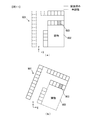
- Flow chart showing processing in automatic parking mode (A) is a plan view showing an example of a parking lot, (b) is a diagram visualizing each point of a landmark represented by point cloud data (A) is a figure showing parking lot data, (b) is a figure showing point cloud data.
- (A) is a figure which shows the present position when a vehicle approaches a parking area in a parking lot
- (b) is an example of data obtained by converting local peripheral information acquired in the position estimation mode from a local coordinate system to a parking lot coordinate system.
- Figure showing (A) is a figure which shows the present position when the vehicle is drive
- (b) is local periphery information obtained by landmark-locating the parking frame line of the front area of a vehicle.
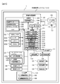
- FIG. 1 is a configuration diagram of an automatic parking system 100 including an information processing apparatus according to an embodiment of the present invention.
- the automatic parking system 100 is mounted on the vehicle 1.
- the automatic parking system 100 includes an external sensor group 102, a car navigation system 107, a vehicle speed sensor 108, a rudder angle sensor 109, an input device 110, a display device 111, a communication device 114, an in-vehicle processing device 120, a vehicle control device 130, and a steering device 131.
- the external sensor group 102, the car navigation system 107, the vehicle speed sensor 108, the rudder angle sensor 109, the input device 110, the display device 111, the communication device 114, the vehicle control device 130, the sensor error database 150, and the environment database 151 are as follows: It is connected to the in-vehicle processing device 120 through a signal line, and exchanges various signals and various data with the in-vehicle processing device 120.
- the external sensor group 102 detects an object existing around the vehicle 1 and outputs the detection information to the in-vehicle processing device 120.
- the external sensor group 102 observes an object around the vehicle 1 using radio waves and infrared rays, a camera 102A that captures the surroundings of the vehicle 1, a sonar 102B that observes objects around the vehicle 1 using ultrasonic waves. Radar 102C. Note that it is not necessary to include all these sensors in the external sensor group 102, and other sensors may be included in the external sensor group 102. Any sensor can be used as the external sensor group 102 as long as it can detect an object existing around the vehicle 1.
- the car navigation system 107 includes a GPS receiver 107A and a storage unit 107B.
- the GPS receiver 107A receives signals from a plurality of satellites constituting the satellite navigation system.
- the storage unit 107B is a nonvolatile storage device and stores a road map 107C.
- the road map 107C includes information related to the road connection structure and latitude / longitude information corresponding to the road position.
- the car navigation system 107 calculates the latitude and longitude representing the position of the car navigation system 107 on the earth, that is, the position of the vehicle 1, based on information included in the signal received by the GPS receiver 107A. At this time, a road corresponding to the position of the vehicle 1 is specified by referring to the road map 107C as necessary, and the position of the vehicle 1 is corrected according to the road. Note that the accuracy of latitude and longitude calculated by the car navigation system 107 does not have to be high accuracy, and may include an error of, for example, several m to 10 m.
- the car navigation system 107 outputs the calculated latitude and longitude information to the in-vehicle processing device 120.
- the vehicle speed sensor 108 and the rudder angle sensor 109 measure the vehicle speed and the rudder angle of the vehicle 1 and output them to the in-vehicle processing device 120.
- the in-vehicle processing device 120 can calculate the moving amount and moving direction of the vehicle 1 by a known dead reckoning technique using the outputs of the vehicle speed sensor 108 and the steering angle sensor 109.
- the input device 110 receives an operation command input from the user to the in-vehicle processing device 120 and outputs an operation command signal corresponding to the input content to the in-vehicle processing device 120.
- Input device 110 includes, for example, response button 110A and automatic parking button 110B. Details of these buttons will be described later.
- the display device 111 is a liquid crystal display, for example, and displays an image output from the in-vehicle processing device 120.
- the input device 110 and the display device 111 may be integrated, and these may be configured as, for example, a touch panel display corresponding to a touch operation. In this case, it is possible to determine that the response button 110A or the automatic parking button 110B has been pressed by the user touching a predetermined area on the display in accordance with the image displayed on the display.
- the communication device 114 is used so that an external device of the vehicle 1 and the in-vehicle processing device 120 can exchange information wirelessly. For example, when the user is outside the vehicle 1, the in-vehicle processing device 120 communicates with the mobile terminal worn by the user using the communication device 114 to exchange information.
- the target with which the communication device 114 communicates is not limited to the user's portable terminal, and can communicate with any device capable of wireless communication.
- the vehicle control device 130 controls the steering device 131, the drive device 132, and the braking device 133 based on the vehicle control command from the in-vehicle processing device 120.
- the steering device 131 operates the steering of the vehicle 1.
- the driving device 132 gives driving force to the vehicle 1.
- the driving device 132 increases the driving force of the vehicle 1 by increasing the target rotational speed of the engine included in the vehicle 1.
- the braking device 133 gives a braking force to the vehicle 1.
- the vehicle control device 130 performs these controls in accordance with a vehicle control command from the in-vehicle processing device 120, so that the vehicle 1 is automatically moved without a user's driving operation, and an arbitrary parking position is set. Can be parked.
- the in-vehicle processing device 120 includes a calculation unit 121, a RAM 122, a ROM 123, a storage unit 124, and an interface 125.
- the arithmetic unit 121 is, for example, a CPU, and executes various arithmetic processes by executing a program. In addition, you may comprise so that all or one part function of the calculating part 121 may be implement
- the RAM 122 is a readable / writable storage area and operates as a main storage device of the in-vehicle processing device 120.
- the ROM 123 is a read-only storage area and stores a program executed by the calculation unit 121.
- This program is expanded in the RAM 122 and executed by the calculation unit 121.
- the calculation unit 121 reads and executes the program developed in the RAM 122, thereby executing a point cloud data acquisition unit 121A, a point cloud data verification unit 121B, a point cloud map generation unit 121C, an absolute position acquisition unit 121D, and a movement amount estimation unit.
- 121E, the position estimation unit 121F, the display control unit 121G, the vehicle control unit 121H, and the mode switching unit 121I operate as functional blocks.
- the point cloud data 122A, the local peripheral information 122B, and the outlier list 122C are generated and temporarily stored in the RAM 122 by a program executed by the calculation unit 121. Details of these functional blocks and information will be described later.
- the storage unit 124 is a non-volatile storage device and operates as an auxiliary storage device of the in-vehicle processing device 120.
- the storage unit 124 stores a point cloud map 124A.
- the point cloud map 124A is information in which coordinate values of a plurality of points each representing an object existing around the vehicle 1 at a place where the vehicle 1 has traveled in the past are recorded in association with the position information of the place. It is.
- parking lot data relating to parking lots in various locations is stored in the storage unit 124 as a point cloud map 124A.
- Parking data includes latitude and longitude representing position information for each parking lot, coordinate values indicating a parking area in the parking lot, and coordinate values of a plurality of points constituting landmarks existing in the parking lot. It is a set. The specific configuration and landmarks of the parking lot data in the point cloud map 124A will be described later.
- the interface 125 performs interface processing of information input / output between the in-vehicle processing device 120 and other devices constituting the automatic parking system 100.
- the error information of the vehicle speed sensor 108 and the steering angle sensor 109 is stored in the sensor error database 150.
- the environment database 151 stores information on allowable accuracy for the control of the vehicle 1 performed by the vehicle control device 130. For these pieces of information, values measured or calculated in advance are used.
- the in-vehicle processing device 120 can verify the feasibility of the point cloud map 124A using the information in these databases. This point will be described later.
- a landmark is an object that exists around the vehicle 1 and has characteristics that can be identified by the external sensor group 102, for example, a parking frame line that is a kind of road surface paint, or an obstacle that hinders the traveling of the vehicle 1. It is a wall of a building. In the present embodiment, vehicles and human beings that are moving objects are not included in the landmark.
- the in-vehicle processing device 120 detects landmarks present around the vehicle 1, that is, points having features that can be identified by the external sensor group 102 based on detection information input from the external sensor group 102.
- landmark detection performed based on detection information input from the external sensor group 102 is referred to as “landmark positioning”.
- the camera 102 ⁇ / b> A outputs an image obtained by photographing the periphery of the vehicle 1 (hereinafter, a photographed image) to the in-vehicle processing device 120.
- the in-vehicle processing device 120 performs landmark positioning using an image captured by the camera 102A. Note that internal parameters such as the focal length of the camera 102 ⁇ / b> A and the image sensor size, and external parameters such as the mounting position and mounting posture of the camera 102 ⁇ / b> A to the vehicle 1 are known and stored in the ROM 123 in advance.
- the in-vehicle processing device 120 can calculate the positional relationship between the subject and the camera 102 ⁇ / b> A using the internal parameters and the external parameters stored in the ROM 123, and perform landmark positioning.
- the sonar 102B and the radar 102C each radiate a sound wave or radio wave of a specific wavelength, and observe the position of the object by measuring the time taken to receive the reflected wave reflected back to the object around the vehicle 1 To do. Then, the obtained position of the object is output to the in-vehicle processing device 120.
- the in-vehicle processing device 120 can perform landmark positioning by acquiring the position of an object input from the sonar 102B or the radar 102C.
- the in-vehicle processing device 120 When performing landmark positioning using the camera 102A, the in-vehicle processing device 120 operates the image recognition program as follows on the captured image of the camera 102A to perform road surface paint such as a parking frame. It may be detected. To detect a parking frame, first, an edge is extracted from an input image by a Sobel filter or the like. Next, for example, a pair of an edge rising which is a change from white to black and an edge falling which is a change from black to white is extracted. When the distance between the pairs is substantially equal to a predetermined first predetermined distance, that is, the thickness of the white line constituting the parking frame, the pair is determined as a parking frame candidate.
- a predetermined first predetermined distance that is, the thickness of the white line constituting the parking frame
- a plurality of parking frame candidates are detected by the same process, and when the interval between the parking frame candidates is substantially the same as the predetermined second predetermined distance, that is, the white line interval of the parking frame, these are detected as parking frames. .
- Road surface paint other than the parking frame is detected by an image recognition program that executes the following processing. First, an edge is extracted from the input photographed image using a Sobel filter or the like. It can be detected by searching for a pixel whose edge strength is larger than a predetermined value and the distance between the edges is a predetermined distance corresponding to the width of the white line.
- the in-vehicle processing device 120 detects other vehicles and humans by, for example, known template matching and excludes them from the measurement results. Furthermore, you may exclude the moving body detected as follows from a measurement result. That is, the in-vehicle processing device 120 calculates the positional relationship between the subject and the camera 102A in the captured image using the internal parameters and the external parameters. Next, the in-vehicle processing device 120 calculates the relative speed between the vehicle 1 and the subject by tracking the subject in the captured images continuously acquired by the camera 102A.
- the in-vehicle processing device 120 calculates the speed of the vehicle 1 using the outputs of the vehicle speed sensor 108 and the steering angle sensor 109, and determines that the subject is a moving object if it does not match the relative speed with the subject. The information regarding this moving body is excluded from the measurement results. Similarly, in landmark positioning using the sonar 102B and the radar 102C, the moving object may be determined and excluded from the measurement result.
- FIG. 2 is a diagram illustrating an example of the point cloud map 124 ⁇ / b> A stored in the storage unit 124.
- FIG. 2 shows an example in which two parking lot data are stored as the point cloud map 124A.
- Each of the parking lot data in the point cloud map 124A includes a coordinate value of each vertex of the parking area, a coordinate value of each point representing a landmark on a two-dimensional plane, and a coordinate value of each point representing a route traveled at the time of storage. It is comprised including.
- the corresponding latitude / longitude and type are recorded in combination.
- the type of landmark represented by each point is recorded as the type.
- the parking lot data in the point cloud map 124A is not limited to the coordinate value on the two-dimensional plane, but may be the coordinate value of the three-dimensional space coordinates including the z coordinate which is the altitude.
- each coordinate value of the parking lot data represents a coordinate value in a coordinate system unique to the parking lot data.
- a coordinate system representing each coordinate value of the parking lot data is referred to as a “parking lot coordinate system”.
- the latitude and longitude recorded in association with each coordinate value represents the absolute position on the earth. Therefore, hereinafter, a coordinate system representing latitude and longitude is referred to as an “absolute coordinate system”.
- the parking lot coordinate system is set based on a predetermined point in the parking lot.
- the position of the vehicle 1 when recording of the parking lot data is started is the origin of the parking lot coordinate system
- the traveling direction of the vehicle 1 is the Y axis of the parking lot coordinate system
- the right side of the vehicle 1 The direction is set to the X axis of the parking lot coordinate system. That is, in the point cloud map 124A, a point on the travel route on which the vehicle 1 has traveled in the past is used as a reference position (first reference position), and the relative position of each point with respect to the first reference position is represented by an absolute coordinate system. It is recorded in association with position information including the latitude and longitude.
- the coordinate values of the parking area are recorded as the coordinate values of the four vertices of the rectangular area when the parking area is rectangular, for example.
- the parking area is not limited to a rectangle, and may be a polygon or an ellipse other than a rectangle.
- one set of parking area coordinate values is recorded in each of the two parking lot data, but a plurality of sets of parking area coordinate values may be recorded for each parking lot data. If it does in this way, about the parking lot where a plurality of parking areas exist, the position of each parking area can be expressed in parking data.
- the outlier list 122C stored in the RAM 122 will be described.
- the in-vehicle processing device 120 estimates the position of the vehicle 1 in the parking lot coordinate system using the point cloud map 124A and the local peripheral information 122B.
- the outlier list 122C stores information on the local peripheral information 122B that is not subject to processing in the position estimation of the vehicle 1.
- the outlier list 122C is appropriately updated by the in-vehicle processing device 120 as will be described later when the position of the vehicle 1 is estimated.
- the local peripheral information 122B stored in the RAM 122 is used when estimating the position of the vehicle 1 in the parking lot coordinate system.
- the local peripheral information 122B stores the coordinate values of each point constituting the landmark detected by the in-vehicle processing device 120 in the position estimation mode described later. This coordinate value is set in accordance with a unique coordinate system set based on the position and orientation of the vehicle 1 when recording of the local peripheral information 122B is started.
- a coordinate system representing each coordinate value of the local peripheral information 122B is referred to as a “local coordinate system”.
- the position of the vehicle 1 at the start of recording of the local peripheral information 122B is the origin of the local coordinate system
- the traveling direction of the vehicle 1 is the Y axis of the local coordinate system
- the right direction of the vehicle 1 is the X axis of the local coordinate system.
- Each is set. That is, in the local peripheral information 122B, a point on the travel route on which the vehicle 1 has traveled and a point different from the above point cloud map 124A is used as a reference position (second reference position). The relative position of is shown.
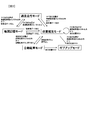
- FIG. 3 is a diagram for explaining the operation modes and transition conditions of the in-vehicle processing device 120.
- the in-vehicle processing device 120 has five operation modes shown in FIG. 3, that is, a normal travel mode, a map storage mode, a position estimation mode, an automatic parking mode, and a give-up mode. Then, these operation modes are switched according to the situation by the mode switching unit 121I.
- the in-vehicle processing device 120 starts from the normal travel mode.
- the vehicle 1 In the normal travel mode, the vehicle 1 is driven by the user.
- the in-vehicle processing device 120 does not generate the point cloud map 124A or estimate the vehicle position on the point cloud map 124A, but only monitors the mode transition condition.
- the mode transition condition is monitored based on the position of the vehicle 1 (hereinafter referred to as “navigation self-position”) acquired from the car navigation system 107 and the point cloud map 124A. Specifically, the latitude and longitude of the parking lot (registered parking lot) where the vehicle 1 registered in advance by the user is parked and the latitude and longitude of the navigation own position are compared.
- the mode transition condition is satisfied, and the mode is changed from the normal travel mode.
- the mode shifts to the map storage mode, and if it exists, the mode transitions to the position estimation mode.
- Whether or not parking lot data near the travel point exists in the point cloud map 124A is determined from latitude / longitude information corresponding to the coordinate values of the landmarks included in each parking lot data of the point cloud map 124A. Can do. That is, the latitude / longitude of the navigation own position is compared with the latitude / longitude information of the landmark of each parking lot data in the point cloud map 124A, and the distance between the travel point and the landmark is calculated from the difference. As a result, if the calculated distance is within a predetermined range, for example, a landmark within 10 m, it is determined that there is parking data near the traveling point, and if there is no landmark, parking data near the traveling point is present. Is determined not to exist.
- the vehicle 1 is driven by the user.
- the in-vehicle processing device 120 performs landmark positioning based on the detection information around the vehicle 1 acquired from the external sensor group 102 included in the vehicle 1 and performs point cloud data that is the basis of parking lot data, that is, registered parking data. It collects information on multiple points that represent white lines, obstacles, parking positions, travel routes, etc. that exist in the parking lot.
- the in-vehicle processing device 120 creates parking lot data using the collected point cloud data, and stores it in the storage unit 124 as a part of the point cloud map 124A.
- the in-vehicle processing device 120 compares the latitude and longitude of the registered parking lot with the latitude and longitude of the navigation own position even during the execution of the map storage mode, as in the normal travel mode. As a result, when the vehicle 1 moves away from the registered parking lot, for example, 100 m or more, the mode changes to the normal travel mode. Further, when the vehicle 1 enters an area where parking lot data exists during execution of the map storage mode, the mode is shifted to the position estimation mode. At this time, whether or not the vehicle 1 has entered the area where the parking lot data exists can be determined by the same method as the presence or absence of the parking lot data in the vicinity of the running point in the normal running mode.
- the latitude / longitude of the navigation own position is compared with the latitude / longitude information of the landmark of each parking lot data in the point cloud map 124A, and the distance between the travel point and the landmark is calculated from the difference.
- the calculated distance is within a predetermined range, for example, a landmark within 10 m, it is determined that the vehicle 1 has entered the area where the parking lot data exists, and if not, the vehicle 1 has entered. Judge that there is no.
- the vehicle 1 is driven by the user.
- the in-vehicle processing device 120 collates detection information around the vehicle 1 acquired from the external sensor group 102 included in the vehicle 1 with information on the point cloud map 124A, and determines the position of the vehicle 1 in the parking lot coordinate system.
- the in-vehicle processing device 120 detects white lines and obstacles in the registered parking lot existing around the vehicle 1 based on the detection information from the external sensor group 102, and a parking lot whose position is indicated by the point cloud map 124A.
- the current position of the vehicle 1 in the parking lot coordinate system is estimated by collating with the coordinate value of each landmark in the data.
- the in-vehicle processing device 120 compares the latitude and longitude of the registered parking lot with the latitude and longitude of the navigation own position even during execution of the position estimation mode, as in the normal travel mode and the map storage mode. As a result, when the vehicle 1 moves away from the registered parking lot, for example, 100 m or more, the mode changes to the normal travel mode. Further, when the vehicle 1 enters an area where no parking lot data exists during execution of the position estimation mode, the mode shifts to the map storage mode. At this time, whether or not the vehicle 1 has entered an area where no parking lot data exists can be determined by a method opposite to the transition condition from the map storage mode to the position estimation mode.
- the latitude / longitude of the navigation own position is compared with the latitude / longitude information of the landmark of each parking lot data in the point cloud map 124A, and the distance between the travel point and the landmark is calculated from the difference.
- the calculated distance is within a predetermined range, for example, when there is no landmark of 10 m or more, it is determined that the vehicle 1 has entered an area where there is no parking lot data. Judge that there is no.
- the vehicle 1 shifts to the automatic parking mode. Further, when the position estimation is not successful and the position of the vehicle 1 in the parking lot coordinate system is lost, the mode is shifted to the give-up mode.
- traveling of the vehicle 1 is controlled by the in-vehicle processing device 120, and the vehicle 1 automatically moves within the registered parking lot without a user's driving operation.
- the in-vehicle processing device 120 moves and parks the vehicle 1 to the parking position designated by the user based on the position of the vehicle 1 in the parking lot coordinate system obtained in the position estimation mode.
- the in-vehicle processing device 120 estimates the position of the vehicle 1 in the parking lot coordinate system even in the automatic parking mode, following the position estimation mode. That is, on the basis of detection information from the external sensor group 102, white lines and obstacles in the registered parking lot existing around the vehicle 1 are detected, and these positions are collated with the point cloud map 124A to determine the parking lot coordinates. The current position of the vehicle 1 in the system is estimated.
- the traveling control of the vehicle 1 is stopped and the mode is shifted to the position estimation mode. Further, when the user presses the automatic parking button 110B and the position estimation is not successful and the position of the vehicle 1 in the parking lot coordinate system is lost, the state shifts to the give-up mode.
- the in-vehicle processing device 120 presents to the user that automatic parking is not possible via the display device 111. During this mode, the in-vehicle processing device 120 does not perform storage of the point cloud map 124A, position estimation of the vehicle 1 in the parking lot coordinate system, or automatic parking control.
- the mode is changed to the normal traveling mode.
- the in-vehicle processing device 120 executes each operation mode as described above.
- the map storage mode, the position estimation mode, and the automatic parking mode will be described in detail in order.
- Map memory mode As described above, when the vehicle 1 falls within a predetermined range centered on the registered parking lot, and the parking lot data near the travel point is not recorded in the point cloud map 124A, the in-vehicle processing device 120 uses the map storage mode. Works with. While operating in the map storage mode, the in-vehicle processing device 120 displays on the screen of the display device 111 that it is operating in the map storage mode, and performs landmark positioning to collect the point cloud data 122A.
- the point cloud data verification unit 121B operates with a trigger that the user stops after moving the vehicle 1 to the parking position and operates the parking brake.
- the point cloud data verification unit 121B determines whether the point cloud data 122A collected in the map storage mode is established as the point cloud map 124A, that is, whether it can be used for position estimation of the vehicle 1 in the position estimation mode or the automatic parking mode. Validate.
- the purpose is that if the collected point cloud data 122A cannot be used for position estimation, the point cloud map 124A created using the point cloud data 124A cannot be estimated and automatic parking fails. It is to prevent in advance.
- the point cloud data verification unit 121B locally sets whether or not the point cloud data 122A acquired in each verification section can be used for position estimation by setting a verification section at predetermined intervals on the travel locus of the vehicle 1.
- the verification can be performed based on two verification factors, i.e., sex and autonomous navigation.
- the local feasibility which is the former verification element, can be determined from, for example, the distribution state of a plurality of points in the point cloud data 122A. Specifically, for example, when the density of the point cloud data 122A acquired within the verification section is equal to or higher than a predetermined value and there is no identical distribution pattern, it is determined that the local feasibility is satisfied. .
- the autonomous navigation which is the latter verification element, can be determined from, for example, the estimation error of the movement amount of the vehicle 1 and the allowable accuracy for the control of the vehicle 1.
- the position estimation error of the vehicle 1 in the known dead reckoning technology using the vehicle speed sensor 108 or the steering angle sensor 109 is acquired from the sensor error database 150, and the passage width in the parking lot or the size of the parking area is acquired.
- the permissible accuracy of the position for the control of the vehicle 1 determined every time is acquired from the environment database 151. And based on these acquired information, it is judged whether the autonomous navigation property is satisfy
- the collected point cloud data 122A can be used for position estimation. For example, even in a verification section where local feasibility does not hold, if the position estimation error by autonomous navigation is sufficiently small and within allowable accuracy, the point cloud data 122A acquired in the verification section can be used for position estimation, It is determined that the point cloud map 124A is established. In this case, when the local feasibility does not hold and the position estimation error by autonomous navigation exceeds the allowable accuracy, it is determined that the point cloud data 122A cannot be used for position estimation.
- the in-vehicle processing device 120 displays a predetermined message or image on the display device 111 and acquires the point cloud data 122A acquired this time. Is inquired to the user as to whether or not to be recorded in the point cloud map 124A. When the user presses the response button 110A in response to this inquiry, the in-vehicle processing device 120 uses the point cloud map generation unit 121C to create parking lot data constituting the point cloud map 124A using the acquired point cloud data 122A. Then, the map is stored in the storage unit 124 and the map storage mode is terminated.
- the in-vehicle processing device 120 lacks information necessary for the point cloud map 124A in the point cloud data 122A acquired this time. Is displayed on the display device 111. Then, when the user presses the response button 110A, the parking lot data constituting the point cloud map 124A is created using the acquired point cloud data 122A, similarly to the case where it is determined that it can be used for position estimation, and the storage unit Then, the map storage mode is ended. At this time, a message that prompts the user to travel again on the same route and acquire the necessary point cloud data 122A may be displayed. Or you may complete
- the operation of the map storage mode by the in-vehicle processing device 120 is divided into two types: extraction of the point cloud data 122A constituting the landmark and recording of the point cloud map 124A based on the extracted point cloud data 122A.
- extraction processing of the point cloud data 122A by the in-vehicle processing device 120 will be described below.
- the in-vehicle processing device 120 secures a temporary recording area in the RAM 122 when transitioning to the map storage mode. Then, the in-vehicle processing device 120 repeats the following processing until the map storage mode ends or transitions to another mode. That is, the in-vehicle processing device 120 has a plurality of points representing landmarks based on detection information acquired from the external sensor group 102 by landmark positioning, specifically, images captured by the camera 102A and observation information by the sonar 102B and radar 102C. Point cloud data 122A is extracted.
- the in-vehicle processing device 120 calculates the amount of movement and the direction of movement of the vehicle 1 from the previous shooting by the camera 102A to the current shooting based on the outputs of the vehicle speed sensor 108 and the steering angle sensor 109.
- the in-vehicle processing device 120 obtains the coordinate value of each point included in the extracted point cloud data 122A based on the positional relationship with the vehicle 1 and the movement amount and movement direction of the vehicle 1, and records them in the RAM 122. Further, the in-vehicle processing device 120 calculates and records the latitude and longitude of each point from the latitude and longitude output by the car navigation system 107. The in-vehicle processing device 120 repeats this process in the map storage mode.
- the coordinate value of each point in the point cloud data 122A is recorded as a coordinate value in a coordinate system set based on the position of the vehicle 1 at the time when the recording of the point cloud data 122A is started.
- this coordinate system is referred to as a “recording coordinate system”.
- the position of the vehicle 1 is the origin of the recording coordinate system
- the traveling direction (posture) of the vehicle 1 is the Y axis of the recording coordinate system
- the right direction of the vehicle 1 is the recording coordinates.
- the coordinate values of are not necessarily constant.
- the in-vehicle processing device 120 obtains the coordinate value of the parking area from the current position of the vehicle 1 and records it in the RAM 122. To do.
- the coordinate values of the parking area are recorded as the coordinate values of the four corners when the vehicle 1 is approximated to a rectangle, for example.
- the coordinate value of the parking area may be determined in consideration of the difference in size between the vehicle 1 and the parking area.
- the in-vehicle processing device 120 performs a recording process of the point cloud map 124A based on the point cloud data 122A as follows.
- the in-vehicle processing device 120 determines a difference between the current position of the vehicle 1 at the time of parking completion, that is, the latitude and longitude of the parking position, from the latitude and longitude of any parking area in the parking lot data already recorded in the point cloud map 124A. Determine whether it is within range. As a result, when there is no parking lot data including a parking area where the difference between the latitude and longitude of the parking position is within a predetermined range, the in-vehicle processing device 120 uses the point cloud data 122A stored in the RAM 122 as a new parking lot. Data is recorded on the point cloud map 124A.
- the in-vehicle processing device 120 uses the information of the point cloud data 122A stored in the RAM 122 as the parking lot. It is determined whether or not the data is merged as data of the same parking lot. For this determination, the in-vehicle processing device 120 first converts the coordinates of the point cloud data 122A so that the position of the parking area included in the parking lot data matches the parking position of the point cloud data 122A recorded in the RAM 122. I do. Next, a point group coincidence rate representing the degree of coincidence between the point group data 122A after coordinate conversion and the point group map 124A is calculated. Then, if the calculated point group coincidence rate is larger than a predetermined threshold value, it is determined that they are integrated, and if they are equal to or less than the threshold value, it is determined that they are not integrated. The specific contents of these processes will be described later.
- the in-vehicle processing device 120 determines that they are not integrated as a result of the determination, the in-vehicle processing device 120 records the point cloud data 122A stored in the RAM 122 as new parking lot data on the point cloud map 124A. On the other hand, when it is determined that they are integrated, the information of the point cloud data 122A stored in the RAM 122 is added to the existing parking lot data of the point cloud map 124A.
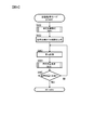
- FIG. 4 is a flowchart showing processing executed by the in-vehicle processing device 120 in the map storage mode.
- the execution subject of each step demonstrated below is the calculating part 121 of the vehicle-mounted processing apparatus 120.
- the calculation unit 121 performs a point cloud data acquisition unit 121A, a point cloud data verification unit 121B, a point cloud map generation unit 121C, an absolute position acquisition unit 121D, a movement amount estimation unit 121E, and a display It functions as the control unit 121G.
- step S501 the calculation unit 121 determines whether or not the map storage mode has been entered. If it is determined that the map storage mode has been entered, the process proceeds to S502. If the map storage mode has not been entered, the process remains in step S501.
- step S502 the calculation unit 121 performs an initialization process.
- a new storage area is secured in the RAM 122.
- the point cloud data 122A extracted by landmark positioning and the position of the vehicle 1 are recorded as coordinate values in the recording coordinate system described above in the subsequent processing.
- step S503 the calculation unit 121 performs the above-described landmark positioning using the information acquired from the external sensor group 102 by the point cloud data acquisition unit 121A. That is, using the captured image of the camera 102A and the observation information of the sonar 102B or the radar 102C, observation values of a plurality of points representing landmarks in the parking lot existing around the vehicle 1 are acquired, and the point cloud data 122A is obtained. Recorded in the RAM 122. Note that the point cloud data 122A acquired at this time is a coordinate value that represents a relative position with respect to the current position of the vehicle 1, and is not a coordinate value in the recording coordinate system. Further, at this time, the calculation unit 121 performs GPS positioning for obtaining the current position of the vehicle 1.
- the latitude / longitude information based on the received signal of the GPS receiver 107A output from the car navigation system 107 is acquired by the absolute position acquisition unit 121D.
- the position in the absolute coordinate system of each point of the point cloud data 122A is acquired by linking the current position of the vehicle 1 represented by the acquired latitude / longitude information and the observed value.
- step S504 the calculation unit 121 estimates the amount of movement of the vehicle 1 from the previous landmark positioning to the current landmark positioning by the movement amount estimation unit 121E and records the vehicle 1 in the recorded coordinate system recorded in the RAM 122. Update the current position of.
- the movement amount of the vehicle 1 can be estimated by a plurality of means. For example, as described above, the movement amount of the vehicle 1 can be estimated from the change in the position of the subject existing on the road surface in the photographed image of the camera 102A. Further, when the car navigation system 107 is equipped with a high-accuracy GPS receiver 107A with a small error, the output thereof may be used.
- the movement amount of the vehicle 1 may be estimated based on the vehicle speed output from the vehicle speed sensor 108 and the steering angle output from the steering angle sensor 109.
- the estimated movement amount is, for example, movement amounts ⁇ x, ⁇ y on the two-dimensional plane, ⁇ representing a change in the direction of the vehicle on the plane.
- the estimated movement amount is, for example, the movement amount ⁇ x, ⁇ y, ⁇ z in the three-dimensional space, and the change in the vehicle orientation in the space.
- Three parameters of ⁇ , ⁇ , and ⁇ are expressed.
- ⁇ corresponds to the amount of rotation about the x axis
- ⁇ corresponds to the amount of rotation about the y axis
- ⁇ corresponds to the amount of rotation about the z axis.
- step S505 the calculation unit 121 temporarily records the point cloud data 122A of the recording coordinate system in the RAM 122.
- the coordinate value of each point of the point cloud data 122A acquired by the landmark positioning in step S503 is converted into the coordinate value of the recording coordinate system.
- the point value data 122A in the RAM 122 is updated with the converted coordinate values as the point value data 122A of the recording coordinate system. That is, the coordinate value of each point of the point cloud data 122A recorded in the RAM 122 is rewritten based on the position and orientation of the vehicle 1 at the time when the recording of the point cloud data 122A is started.
- step S506 the calculation unit 121 determines whether or not the vehicle 1 has been parked. Until the parking brake of the vehicle 1 is actuated, it is determined that the parking is not completed, the process returns to step S503, and the landmark positioning and the recording of the point cloud data 122A are continued. When the parking brake of the vehicle 1 is operated, it is determined that parking is completed, and the process proceeds to step S507.
- step S507 the calculation unit 121 determines map feasibility of the point cloud data 122A recorded in the RAM 122 in step S505 by the point cloud data verification unit 121B.
- verification regarding the feasibility of the point cloud map 124A is performed for each point of the point cloud data 122A.
- the calculation unit 121 causes the display control unit 121G to display the determination result on the display device 111 and determine whether to record the point cloud data 122A on the point cloud map 124A.
- step S507 the information indicating the determination result of the map feasibility performed in step S507 is recorded in combination with the coordinate value of each point when the point cloud data 122A is recorded in the point cloud map data 124A later in step S514 or S515. Is done.
- step S508 the calculation unit 121 determines whether the user has approved the storage of the point cloud map 124A.
- the user performs a predetermined memory approval operation using the response button 110A, it is determined that the storage of the point cloud map 124A has been approved, and the process proceeds to step S509.
- the user does not perform the storage approval operation, it is determined that the storage of the point cloud map 124A has not been approved, and the flowchart of FIG. 4 ends. In this case, the point cloud data 122A recorded in the RAM 122 is discarded, and the point cloud map 124A is not recorded.
- step S509 the calculation unit 121 performs GPS positioning to obtain the parking position of the vehicle 1. That is, the latitude / longitude information of the parking position is acquired by acquiring the latitude / longitude information based on the reception signal of the GPS receiver 107A output from the car navigation system 107 by the absolute position acquisition unit 121D. And based on the acquired latitude longitude, the coordinate value in the recording coordinate system of the parking area corresponding to a parking position is recorded. That is, the coordinate value in the recording coordinate system of the parking position is calculated from the difference between the latitude and longitude of the current position of the vehicle 1 last acquired in step S503 and the latitude and longitude of the parking position acquired in step S509. Then, the coordinate values of the four vertices of the parking area corresponding to the parking position are calculated and recorded in the RAM 122.
- step S510 the calculation unit 121 determines whether or not the parking lot data including the parking area where the difference between the latitude and longitude is within the predetermined range is recorded in the point cloud map 124A with respect to the parking position acquired in step S509. judge.
- the difference between the latitude and longitude of the parking position is within a predetermined range. Determine if it exists.
- the process proceeds to step S511, and if not, the process proceeds to step S515.
- the parking lot data corresponding to the parking position is already recorded in the point cloud map 124A only when the latitude / longitude difference from the parking position is within a predetermined range for all four vertices of the parking area. May be.
- the parking lot data of the point cloud map 124A including the parking area where the latitude / longitude difference from the parking position is determined to be within the predetermined range in step S510 is referred to as “target parking lot data”.
- step S511 the calculation unit 121 performs coordinate conversion of the point cloud data 122A recorded in the RAM 122 in step S505 from the recording coordinate system to the parking lot coordinate system of the target parking lot data by the point cloud map generation unit 121C.
- a coordinate conversion formula from the recording coordinate system to the parking lot coordinate system is derived so that the latitude and longitude of the parking area in the target parking lot data coincide with the latitude and longitude of the parking position acquired in step S509.
- the coordinate values of the respective points constituting the landmark and the current position of the vehicle 1 are obtained as the parking lot coordinates of the target parking lot data. Convert to coordinate values in the system.
- step S512 the calculation unit 121 calculates a point group coincidence rate IB between the point group data 122A subjected to coordinate conversion in step S511 and the target parking lot data.
- “Din” is the number of points within a predetermined value of the distance from any point of the target parking lot data among the points of the point cloud data 122A subjected to coordinate conversion in step S511. .
- “D1” is the number of points in the point cloud data 122A stored in the RAM 122
- “D2” is the number of points in the point cloud data 122A of the target parking lot data. If the point group coincidence rate IB is calculated in step S512, the process proceeds to step S513.
- step S513 the calculation unit 121 determines whether the point cloud coincidence rate IB calculated in step 512 is greater than a predetermined threshold value. As a result, when it is determined that the point group coincidence rate IB is greater than the threshold value, the process proceeds to step S514, and when it is determined that the point group match rate IB is equal to or less than the threshold value, the process proceeds to step S515.
- step S514 the calculation unit 121 performs a merging process of the point cloud data 122A coordinate-converted in step S511 and the target parking lot data by the point cloud map generation unit 121C.
- a merge process is performed to generate a new point cloud map 124A. To do.
- the flowchart of FIG. 4 is terminated.
- step S515 which is executed when a negative determination is made in step S510 or S513, the calculation unit 121 acquires the point cloud data 122A coordinate-converted in step S511 and the point cloud data 122A acquired in step S509 by the point cloud map generation unit 121C.
- the latitude / longitude of the parking position and the coordinate value of the parking area corresponding to the parking position are recorded on the point cloud map 124A as new parking lot data.
- FIG. 5 is a flowchart showing processing executed by the in-vehicle processing device 120 in the position estimation mode.
- the execution subject of each step demonstrated below is the calculating part 121 of the vehicle-mounted processing apparatus 120.
- the calculation unit 121 functions as a point cloud data acquisition unit 121A, an absolute position acquisition unit 121D, a movement amount estimation unit 121E, a position estimation unit 121F, and a display control unit 121G when performing the processing shown in FIG.
- step S601 the calculation unit 121 determines whether or not the position estimation mode has been entered. If it is determined that the position estimation mode has been entered, the process proceeds to S602. If the position estimation mode has not been entered, the process remains in step S601.
- step S602 the calculation unit 121 performs GPS positioning to obtain the current position of the vehicle 1. That is, the latitude and longitude information based on the received signal of the GPS receiver 107A output from the car navigation system 107 is acquired by the absolute position acquisition unit 121D, thereby acquiring the latitude and longitude corresponding to the current position of the vehicle 1.
- step S603 the calculation unit 121 determines whether or not the point cloud map 124A has map feasibility around the current position of the vehicle 1.
- the presence / absence of the parking lot data having a latitude / longitude within a certain range from the current position of the vehicle 1 and having a map feasibility is included in the route data. judge. Whether or not the map is feasible can be determined from the information recorded in step S507 in FIG. 4 when the point cloud data 122A acquired in the map storage mode is recorded in the point cloud map 124A.
- step S602 the process returns to step S602 to continue GPS positioning.
- step S604 the calculation unit 121 performs an initialization process.
- initialization of the local peripheral information 122B stored in the RAM 122 and initialization of the current position of the vehicle 1 stored in the RAM 122 are performed. Specifically, if the previous information is recorded, it is deleted, and a new coordinate system is set as the above-mentioned local coordinate system.
- This local coordinate system is set based on the position and posture of the vehicle 1 when step S604 is executed. For example, the position of the vehicle 1 when step S604 is executed is set as the origin of the local coordinate system, and the X axis and Y axis of the local coordinate system are set according to the orientation when step S604 is executed. In the initialization of the current position of the vehicle 1, the current position of the vehicle 1 is set to the origin (0, 0).
- step S605 the calculation unit 121 performs self-position estimation by the position estimation unit 121F.
- the current position in the parking lot coordinate system of the vehicle 1 is estimated according to the procedure of the flowchart shown in FIG.
- step S606 the calculation unit 121 determines whether or not the own position, that is, the current position of the vehicle 1 in the parking lot coordinate system can be estimated in step S605.
- the self-position diagnosis performed in step S627 of the flowchart shown in FIG. 6 described later, it is determined whether or not the self-position has been correctly estimated.
- step S607 if it is determined that the reliability of the self position is low, it is determined that the self position has not been correctly estimated, and the process returns to step S605 to continue the self position estimation.
- step S607 the calculation unit 121 causes the display control unit 121G to display the self-position estimation result performed in step S605 on the display device 111.
- the self-position estimation result is displayed so that the user can recognize it.
- an overhead view image showing a state of the vehicle 1 viewed from above is generated and displayed on the display device 111, and the vehicle 1 represented by the point cloud map 124A on the overhead image is displayed. The positional relationship between surrounding objects and the vehicle 1 may be indicated.
- step S608 the calculation unit 121 determines whether or not the self-position displayed in step S607 has approached within a predetermined distance, for example, within 10 m, from any parking position in the parking lot data of the point cloud map 124A. Until the self-position approaches within 10 m of the parking position, the process returns to step S605 and the self-position estimation is continued. When the self-position approaches within 10 m, the process proceeds to step S609. That is, when the difference between the coordinate value of the parking position in the parking lot coordinate system represented by the point cloud map 124A and the position of the vehicle 1 estimated in step S605 is less than the predetermined distance, the determination in step S608 is affirmative and the next The process proceeds to step S609.
- a predetermined distance for example, within 10 m
- step S609 the calculation unit 121 displays on the display device 111 that automatic parking is possible by the display control unit 121G. Thereby, the user is inquired whether or not the automatic parking of the vehicle 1 is performed.
- step S610 the calculation unit 121 determines whether or not the automatic parking button 110B has been pressed by the user. If the user has not pressed the automatic parking button 110B, the process returns to step S609 to continue displaying that automatic parking is possible. If the user has pressed the automatic parking button 110B, the process proceeds to step S611.
- step S611 the calculation unit 121 switches the operation mode of the in-vehicle processing device 120 from the position estimation mode to the automatic parking mode by the mode switching unit 121I. Then, the automatic parking mode operation is executed according to the procedure of the flowchart shown in FIG. If automatic parking mode is performed by step S611, the flowchart of FIG. 5 will be complete
- FIG. 6 is a flowchart showing the self-position estimation process executed by the in-vehicle processing device 120 in step S605 of FIG.
- step S621 the calculation unit 121 performs the same processing as that in steps S503 to 505 in FIG. 4 to acquire the local peripheral information 122B. That is, in step S621, landmark positioning is performed in the same procedure as in step S503, and observation values of a plurality of points representing landmarks in a parking lot existing around the vehicle 1 are acquired and stored in the RAM 122 as point cloud data 122A. Record. In step S622, the movement amount of the vehicle 1 is estimated in the same procedure as in step S504, and the current position of the vehicle 1 in the local coordinate system is updated.
- step S623 in the same procedure as in step S505, based on the current position of the vehicle 1 updated in step S622, the observed value of each point of the point cloud data 122A acquired by the landmark positioning in step S621 is converted into the coordinate value of the local coordinate system. And temporarily recorded in the RAM 122 as the local peripheral information 122B. Thereby, the local peripheral information 122B according to the current position of the vehicle 1 is newly generated, and the content of the local peripheral information 122B in the RAM 122 is updated.
- step S623 When the execution of step S623 is completed, the calculation unit 121 selects the local peripheral information 122B updated in step S623 in step S624.
- a point to be used in the subsequent matching processing is selected from the points where the coordinate values are recorded as the local peripheral information 122B. That is, each point in the local peripheral information 122B may include a point that has a distribution shape different from that of the point cloud map 124A and cannot be matched due to a cumulative error in estimating the movement amount of the vehicle 1. For this reason, the local peripheral information 122B selection process performed in step S623 adaptively selects a point in the local peripheral information 122B that has a small error and can be matched.
- step S624 the calculation unit 121 performs a matching process shown in detail in FIG. 8 in step S625.
- a relational expression representing the correspondence between the local coordinate system and the parking lot coordinate system that is, a coordinate conversion formula from the local coordinate system to the parking lot coordinate system is obtained.
- the parking lot coordinate system is a coordinate system used in the point cloud map 124A, and a point on the past travel route of the vehicle 1 is set as a reference position (first reference position).
- the local coordinate system is a coordinate system used in the local peripheral information 122B, and a point on the past travel route of the vehicle 1 different from the parking lot coordinate system is set as a reference position (second reference position).
- the calculation unit 121 relates the first reference position in the point cloud map 124A (parking lot coordinate system) and the second reference position in the local peripheral information 122B (local coordinate system). Is calculated.
- step S626 the calculation unit 121 uses the coordinates of the vehicle 1 in the local coordinate system updated in step S622 and the coordinate conversion formula obtained in step S625, that is, the coordinates of the vehicle 1 in the parking lot coordinate system, that is, Calculate the estimated self-position.
- the process proceeds to step S627.
- step S627 the calculation unit 121 executes self-position diagnosis for the estimated self-position calculated in step S626.
- the reliability of the self-position estimated in step S626 is determined using the following three indices.
- the first index is an error in the current position of the local coordinate system. Specifically, using the outputs of the vehicle speed sensor 108 and the steering angle sensor 109, the movement amount of the vehicle 1 estimated by a known dead reckoning technique and the movement amount of the self-position estimated in step S626 in a predetermined period are obtained. Compare. As a result, when these differences are larger than a predetermined threshold, it is determined that the reliability of the self-position is low.
- the second index is an error amount between corresponding points calculated at the time of matching. Specifically, when the amount of error between corresponding points is larger than a predetermined threshold, it is determined that the reliability of the self position is low.
- the third index is the presence or absence of a similar solution at the time of matching. Specifically, when a similar solution is searched by a method such as translating by the width of the parking frame with respect to the self-position solution obtained at the time of matching, the error amount between corresponding points is about the same in both cases. If so, it is determined that the reliability of the self-position is low.
- step S627 for example, when it is determined that the reliability is high in all the three indexes, it is determined that the self-position has been correctly estimated. On the other hand, if it is determined that the reliability is low with at least one of the indices, it is determined that the self-position has not been correctly estimated. If the self-position estimation result is evaluated in this way, self-position estimation is completed, and the process proceeds from step S605 in FIG. 5 to the next step S606. Note that all three indicators need not be used. Moreover, you may perform a self-position diagnosis using another parameter
- FIG. 7 is a flowchart showing the local peripheral information 122B selection process executed by the in-vehicle processing device 120 in step S624 of FIG.
- step S680 the calculation unit 121 calculates a trajectory traveled by the vehicle 1 in the position estimation mode.
- the trajectory of the vehicle 1 from the start of the position estimation mode to the present is calculated using the estimation result of the movement amount of the vehicle 1 performed in step S622 of FIG.
- the trajectory of the vehicle 1 can be calculated by interpolating a plurality of coordinate points representing the position of the vehicle 1 in the local coordinate system calculated from the movement amount of the vehicle 1 estimated in step S622.
- step S681 the calculation unit 121 calculates an effective range in matching for each point of the local peripheral information 122B updated in step S623 of FIG.
- a range in which the shape error is smaller than that of the point cloud map 124A is calculated as an effective range that can be matched.
- This effective range can be determined from the length and shape of the trajectory calculated in step S680. That is, as the moving distance of the vehicle 1 increases and the turning amount of the vehicle 1 increases, an estimation error is likely to occur in the coordinate values of each point obtained from the local peripheral information 122B. On the other hand, if there are too few points from which coordinate values are obtained as the local peripheral information 122B, matching becomes difficult.
- the points in the effective range are points that range from the current position of the vehicle 1 to the predetermined minimum distance D [m]. Get as. After that, the amount of change in the angle of the tangent line of the trajectory is accumulated, and the points around the trajectory within the range up to the position where the accumulated value changes beyond the predetermined angle threshold ⁇ [deg] Get as a point inside.
- a range of a predetermined range X [m] ⁇ Y [m] centered on the locus is set as the effective range of the local peripheral information 122B. That is, the effective range of the local peripheral information 122B has a shape along the obtained locus.
- step S682 the calculation unit 121 acquires each point in the effective range obtained in step S681 as a point representing the local peripheral information 122B. As a result, the local peripheral information 122B is selected. When the local peripheral information 122B is selected in this way, the process proceeds from step S624 in FIG. 6 to the next step S625.
- FIG. 8 is a flowchart showing the matching process executed by the in-vehicle processing device 120 in step S625 of FIG.
- step S641 the calculation unit 121 applies the outlier list 122C stored in the RAM 122 to the local peripheral information 122B.
- the points described in the outlier list 122C are temporarily excluded from the processing target.
- the application range of the outlier list 122C in step S641 is the following steps S642 to S653. That is, after the outlier list 122C is updated in step S654 described later, the points that were previously included in the outlier list 122C are also included in the processing target.
- steps S641 to S643 cannot be executed, the execution is started from step S650. If the outlier list 122C is applied in step S641, the process proceeds to step S642.
- step S642 the calculation unit 121 obtains the coordinate values of each point of the latest local peripheral information 122B, that is, each point representing the landmark detected by the landmark positioning performed in step S621 in FIG. 6, in step S603 in FIG.
- the map is converted into the coordinate value of the parking lot coordinate system in the parking lot data determined to have map formation. This conversion is realized by using the current position in the local coordinate system of the vehicle 1 updated in step S622 in FIG. 6 and the coordinate conversion formula from the local coordinate system calculated in the previous time to the parking lot coordinate system.
- calculation unit 121 calculates instantaneous coincidence IC between local peripheral information 122B coordinate-converted in step S642 and the parking lot data used for the coordinate conversion.
- step S642 “DIin” is determined in advance as a distance from any point of the parking lot data in the point cloud map 124A among the points of the latest local peripheral information 122B whose coordinates are converted in step S642. The number of points below the threshold value.
- “DIall” is the number of points detected in the landmark positioning in step S621.
- step S644 the calculation unit 121 determines whether or not the instantaneous coincidence IC calculated in step S643 is larger than a predetermined threshold value. As a result, when it is determined that the instantaneous matching degree IC is larger than the threshold value, the process proceeds to step S650, and when it is determined that the instantaneous matching degree IC is equal to or less than the threshold value, the process proceeds to step S645.
- step S645 the calculation unit 121 detects a periodic feature, for example, a plurality of arranged parking frames, from the local peripheral information 122B.
- a periodic feature for example, a plurality of arranged parking frames
- the parking frame line can be detected from the points arranged at intervals corresponding to the thickness of the white line.
- step S646 operation unit 121 determines whether or not a periodic feature has been detected in step S645. If it is determined that it has been detected, the operation proceeds to step S647. If it is determined that it has not been detected, operation unit 121 proceeds to step S650. .
- step S647 the calculation unit 121 calculates the period of the periodic feature detected in step S645, for example, the width of the parking frame.
- the width of the parking frame here is an interval between white lines constituting the parking frame.
- step S648 the calculation unit 121 uses the coordinate conversion formula calculated in the previous step S653 as a reference, and the degree of instantaneous coincidence between the local peripheral information 122B and the parking lot data when the coordinate conversion formula is changed in a plurality of ways. IC is calculated.
- the coordinate conversion formula is changed in a plurality of ways so that each point of the local peripheral information 122B after the coordinate conversion is shifted by an integral multiple of the periodic feature detected in step S645.
- the overall matching degree IW is calculated for each of the plurality of coordinate conversion formulas after the change.
- the overall matching degree IW is calculated by, for example, the following formula (3).
- IW DWin / DWall ... Formula (3)
- DWin is the distance from any point of the parking lot data of the point cloud map 124A among the points of the local peripheral information 122B coordinate-converted using the coordinate conversion expression described above. The number of points within a predetermined value.
- DWall is the number of points detected in Step S621. If the overall matching degree IW is calculated in step S648, the process proceeds to step S649.
- step S649 the calculation unit 121 stores, in the RAM 122, a coordinate conversion formula that gives the maximum overall matching degree IW among the plurality of overall matching degrees IW calculated in step S648, and then proceeds to step S650.
- step S650 In the association process in step S650, the error minimization process in step S651, and the convergence determination process in step S652, which will be described below, an ICP (Iterative Closest Point) algorithm that is a known point cloud matching technique may be used. it can.
- ICP Intelligent Closest Point
- step S650 that is executed when the determination in step S644 is affirmative, the determination in step S646 is negative, the execution of step S649 is completed, or the determination in step S652 is negative, the calculation unit 121
- the points included in the parking lot data of the group map 124A are associated with the points included in the local peripheral information 122B.
- these points are associated using different coordinate transformation formulas depending on the processing executed previously. That is, when executed after step S644 or step S649, the coordinate transformation from the local peripheral information 122B to the parking lot data is performed using the coordinate transformation formula recorded in the RAM 122.
- step S650 when affirmative determination is made in step S644 and step S650 is executed, the coordinate conversion formula calculated in step S653 executed last time is used.
- step S650 is executed after step S649, the coordinate conversion formula stored in step S649 is used.
- the process proceeds to step S651.
- step S651 the calculation unit 121 minimizes the error between the points associated in step S650.
- the coordinate conversion formula is changed so that the sum of the indices of the distances between the points associated in step S650 is minimized.
- the sum of the distance indices between the associated points for example, the sum of the absolute values of the distances between them can be adopted.
- step S652 the calculation unit 121 determines whether or not the error has converged. As a result, when it is determined that it has converged, the process proceeds to step S653, and when it is determined that it has not converged, the process returns to step S650 and the association process and the error minimization process are continued.
- step S653 the calculation unit 121 stores the coordinate conversion formula last changed in step S651 in the RAM 122, and proceeds to step S654.
- step S654 the calculation unit 121 updates the outlier list 122C as follows. First, the existing outlier list 122C stored in the RAM 122 is cleared. Next, the coordinate value of each point of the local peripheral information 122B is converted into the coordinate value of the parking lot coordinate system using the coordinate conversion formula recorded in step 653, and each point constituting the local peripheral information 122B and its point Calculates the distance to the points constituting the corresponding point cloud map 124A, that is, the Euclidean distance. If the calculated distance is longer than a predetermined distance, the point of the local peripheral information 122B is added to the outlier list 122C.
- the outlier list 122C may be added to the outlier list 122C using a further condition such as adding to the outlier list 122C that it is spatially located at the end.
- a spatial end is a point that is far from another point, such as a point acquired when recording is started.
- FIG. 9 is a flowchart showing the automatic parking mode process executed by the in-vehicle processing device 120 in step S611 of FIG.
- the execution subject of each step demonstrated below is the calculating part 121 of the vehicle-mounted processing apparatus 120.
- the calculation unit 121 functions as the position estimation unit 121F and the vehicle control unit 121H when performing the processing shown in FIG.
- the in-vehicle processing device 120 automatically parks when the position of the vehicle 1 is successfully estimated in the position estimation mode and the latitude and longitude of the vehicle 1, that is, the absolute position is within a predetermined range from the parking position.
- the transition from the position estimation mode to the automatic parking mode is performed only while the button 110B is pressed. That is, automatic control of the vehicle 1 is performed with the user's approval.
- step S661 the calculation unit 121 performs self-position estimation using the position estimation unit 121F, and estimates the position of the vehicle 1 in the parking lot coordinate system. Note that the processing content in this step is the same as that in step S605 in FIG. 5 and has already been described with reference to FIG.
- step S662 the calculation unit 121 generates a travel route from the position estimated in step S661 to the parking position stored in the point cloud map 124A by a known route generation method. Next, the process proceeds to step S663.
- step S663 the calculation unit 121 controls the running state of the vehicle 1 via the vehicle control device 130 by the vehicle control unit 121H.
- the vehicle-mounted processing device 120 outputs a predetermined vehicle control command to the vehicle control device 130, whereby the steering device 131, the drive device 132, and the braking device 133 are output. Are respectively controlled, and the vehicle 1 is moved to the parking position along the route generated in step S662.
- step S664 as in step S661, calculation unit 121 performs self-position estimation using position estimation unit 121F, and estimates the position of vehicle 1 in the parking lot coordinate system.
- step S665 the calculation unit 121 determines whether or not the parking of the vehicle 1 is completed, that is, whether or not the vehicle 1 has reached the parking position. As a result, when it is determined that parking is not completed, the process returns to step S663 to continue control of the vehicle 1, and when it is determined that parking is completed, the flowchart of FIG. 9 is terminated.
- FIG. 10A is a plan view showing an example of a parking lot 901.
- the parking lot 901 includes a plurality of parking areas provided around the building 902. Each parking area is surrounded by a parking frame line such as a white line painted on the road surface. There is only one entrance of the parking lot 901 in the lower left of the figure.
- a parking lot 901 when the vehicle 1 is parked in the parking area 903 indicated by hatching in FIG. 10A, an operation example when the in-vehicle processing device 120 operates in the map storage mode will be described below. .
- the in-vehicle processing device 120 detects a parking frame line in the parking lot 901 as a landmark.
- the position of the vehicle 1 is represented by a triangle, and the acute angle of the triangle indicates the traveling direction of the vehicle 1.
- step S501 YES in FIG. 4
- the in-vehicle processing device 120 starts landmark positioning (steps S502, S503), and the points that constitute the parking frame line. Coordinate values are recorded in the RAM 122 as point cloud data 122A (steps S504 and S505). Then, the processes of steps S503 to S506 in FIG. 4 are repeated until the parking of the vehicle 1 in the parking area 903 is completed.
- FIG. 10B is a diagram in which each landmark point represented by the point cloud data 122A stored in the RAM 122 is visualized.
- a solid line represents a point group of landmarks stored in the RAM 122
- a broken line represents a landmark that is not stored in the RAM 122. Since the range that can be sensed by the external sensor group 102 of the vehicle 1 is limited, as shown in FIG. 10B, when the vehicle 1 is near the entrance of the parking lot 901, the vicinity of the entrance of the parking lot 901 Only the parking frame line is recorded in the point cloud data 122A.
- the in-vehicle processing device 120 may record the point cloud of the entire landmark of the parking lot 901 in the point cloud data 122A. it can.
- step S508 When the user stops the vehicle 1 in the parking area 903 and presses the response button 110A to approve the storage of the point cloud map 124A (step S508: YES), the in-vehicle processing device 120 transmits the latitude of the vehicle 1 from the car navigation system 107. The longitude is acquired, and the coordinate values of the four corners of the parking area 903 are recorded (step S509).
- step S510 When the parking lot data whose difference from the current latitude / longitude of the vehicle 1 is within the predetermined range is not recorded in the point cloud map 124A (step S510: NO), the point cloud data 122A stored in the RAM 122 is used as the point cloud map. New data constituting 124A, that is, new parking lot data is recorded in the storage unit 124 (step S515).
- the parking lot data shown in FIG. 11 (a) is an example of data obtained when the vehicle 1 travels to the right from the entrance of the parking lot 901 shown in FIG. 10 (a) and reaches the parking area 903. is there. In this case, since the vehicle traveled to the right as compared with FIG. 10 (a), data is not acquired for the parking frame line indicated by the dotted line in FIG. 11 (a) and is recorded as the parking lot data on the point cloud map 124A. Absent.
- the point cloud data 122A shown in FIG. 11B is an example of data obtained when the vehicle 1 travels to the left from the entrance of the parking lot 901 and reaches the parking area 903, for example.
- the point cloud data of the parking frame line indicated by the dotted line in FIG. 11B is not acquired.
- the point cloud data 122A shown in FIG. 11B the vehicle 1 is not directly facing the parking lot 901 when the map storage mode is changed, so that the parking lot 901 is compared with FIG. It is recorded as being inclined overall.
- step S508 when the user stops the vehicle 1 in the parking area 903 and presses the response button 110A to approve the storage of the point cloud map 124A (step S508: YES), the in-vehicle processing device 120 displays the point cloud map. It is determined that the parking lot data whose difference from the current latitude / longitude of the vehicle 1 is within a predetermined range is recorded in 124A (step S510: YES). Then, coordinate conversion of the point cloud data 122A is performed with reference to the parking positions in FIGS. 11A and 11B, that is, the parking area 903 (step S511). Thereafter, the point cloud coincidence rate IB is calculated (step S512).
- step S513 YES
- the point cloud data 122A shown in FIG. 11B is integrated (step S514).
- the parking frame line data on the left side in the figure that was not recorded in FIG. 11A is newly recorded in the point cloud map 124A.
- the density of points representing these in the point cloud map 124A is high.
- FIG. 12A is a diagram illustrating a current position when the vehicle 1 approaches the parking area 903 in the parking lot 901. In FIG. 12 (a), the vehicle 1 faces rightward in the figure.
- FIG. 12B shows the local peripheral information 122B acquired in the position estimation mode while the vehicle 1 reaches the position shown in FIG. 12A from the entrance of the parking lot 901, from the local coordinate system to the parking lot coordinate system.
- the parking frame line represented by the local peripheral information 122B and the trajectory of the vehicle 1 are indicated by a broken line and a dotted line, respectively.
- Parking frame lines and trajectories indicated by broken lines represent points of the parking frame lines and trajectories in the local peripheral information 122B outside the effective range, that is, points that are described in the outlier list 122C and are not subject to matching processing.
- the parking frame line and the trajectory indicated by dotted lines represent the points of the parking frame line and the trajectory in the local peripheral information 122B within the effective range.
- FIG. 13A is a diagram illustrating a current position when the vehicle 1 is traveling toward the parking area 903 in the parking lot 901. In FIG. 13A, the vehicle 1 faces upward in the figure.
- FIG. 13B shows the front frame of the vehicle 1 when the vehicle 1 is at the position shown in FIG. 13A, that is, the parking frame line of the portion surrounded by the broken circle in FIG.
- FIG. 13B shows the example of the data which converted the coordinate value of each point of the local periphery information 122B obtained by mark positioning from the local coordinate system to the parking lot coordinate system. That is, the data shown in FIG. 13B is point group data detected from the latest photographed image and processed in step S642 of FIG. 8 in the local peripheral information 122B. However, in FIG. 13B, this data is represented not by dots but by broken lines.
- the position of the vehicle 1 is also shown for comparison with FIG.
- the parking frame line data is present on the left side of the vehicle 1 without any breaks, whereas the parking frame line data is present only on the front side of the vehicle 1 on the right side of the vehicle 1. doing.
- FIG. 13C shows the correlation between the point cloud map 124A and the local peripheral information 122B shown in FIG. 13B when the estimation result of the position of the vehicle 1 in the parking lot coordinate system includes an error.
- FIG. 13C since the previous position estimation result is approximately shifted by one of the width of the parking frame, the local peripheral information 122B existing on the right side of the vehicle 1 is shifted from the point cloud map 124A. Yes.
- the instantaneous coincidence IC is calculated in step S643 in FIG. 8 in such a state, the instantaneous coincidence IC with respect to the right side of the vehicle 1 becomes a low value due to the aforementioned deviation.
- step S644 NO
- the parking frame is detected as a periodic feature (steps S645, S646: YES), and the width of the parking frame is calculated from the point cloud map 124A. (Step S647). Then, the local peripheral information 122B after coordinate conversion is moved for every integer multiple of the width of the parking frame, and the overall matching degree IW is calculated (step S648).
- FIG. 14A, 14B, and 14C are examples of the relationship with the point cloud map 124A when the local peripheral information 122B shown in FIG. 13C is moved by an integer multiple of the width of the parking frame.
- FIG. 14A to 14C the local peripheral information 122B after coordinate conversion is moved upward in the drawing by +1, 0, and ⁇ 1 times the width of the parking frame.
- the local peripheral information 122B moves to the upper side of the figure by one of the width of the parking frame, so that the deviation between the local peripheral information 122B and the point cloud map 124A is enlarged. For this reason, the overall matching degree IW in FIG. 14A is smaller than that in the case of not moving.
- the local peripheral information 122B has not moved, and as shown in FIG. 13C, the local peripheral information 122B and the point cloud map 124A are shifted by one of the width of the parking frame. .
- the local peripheral information 122B moves by one of the width of the parking frame on the lower side in the figure, so that the local peripheral information 122B and the point cloud map 124A substantially match. For this reason, the overall matching degree IW in FIG. 14C is larger than the case where the local peripheral information 122B is not moved.
- the in-vehicle processing device 120 that is an information processing device mounted on the vehicle 1 relates to a plurality of points that respectively represent objects based on information from the external sensor group 102 that detects objects existing around the vehicle 1.
- a point cloud data acquisition unit 121A that acquires the group data 122A, a movement amount estimation unit 121E that estimates the movement amount of the vehicle 1, and a point on the travel route of the vehicle 1 as a first reference position, with respect to the first reference position
- a storage unit 124 that stores the relative positions of a plurality of points as a point cloud map 124A that is recorded in association with position information including latitude and longitude, the point cloud map 124A, the point cloud data 122A, and the movement amount of the vehicle 1
- a position estimation unit 121F for estimating the position of the vehicle 1.
- the position estimation unit 121F Based on the point cloud data 122A and the amount of movement of the vehicle 1, the position estimation unit 121F generates local peripheral information 122B having a point on the travel route of the vehicle 1 different from the point of the first reference position as the second reference position ( Based on the point cloud map 124A and the local peripheral information 122B, a relational expression (coordinate conversion expression) representing the relationship between the first reference position and the second reference position is calculated (steps S649 and S651 in FIG. 8). ). Then, the position of the vehicle 1 is estimated using the calculated coordinate conversion formula (step S626 in FIG. 6). Since it did in this way, the position of the vehicle 1 can be correctly estimated from map data.
- the in-vehicle processing device 120 generates the point cloud map 124A based on the point cloud data 122A and the movement amount of the vehicle 1 (steps S514 and S515 in FIG. 4), the point cloud map generation unit 121C, and the point cloud map generation unit
- the point cloud data 122A is verified regarding the feasibility of the point cloud map 124A generated by 121C (step S507 in FIG. 4), and further provided with a point cloud data verification unit 121B.
- the storage unit 124 stores the point cloud map 124A generated by the point cloud map generation unit 121C. Since it did in this way, since in-vehicle processor 120 itself can create point cloud map 124A which can be used in position estimation, it is not necessary to create point cloud map 124A beforehand.
- the in-vehicle processing device 120 further presents the verification result of the point cloud data 122A by the point cloud data verification unit 121B to the user (step S507), and further includes a verification result presentation unit, that is, a display control unit 121G. Since it did in this way, it can notify a user in advance whether the point cloud map 124A produced
- the point cloud data verification unit 121B is at least one of a distribution state of a plurality of points in the point cloud data 122A, a movement amount estimation error by the movement amount estimation unit 121E, and an allowable accuracy for control of the vehicle 1. Based on the above, it is possible to verify the point cloud data 122A regarding the feasibility of the point cloud map 124A. In this way, the feasibility of the point cloud map 124A can be accurately determined in advance.
- the in-vehicle processing device 120 is connected to the vehicle speed sensor 108 that detects the vehicle speed of the vehicle 1 and the steering angle sensor 109 that detects the steering angle of the vehicle 1.
- the point cloud data verification unit 121B determines whether or not to use the point cloud data 122A acquired in the verification section on the traveling locus of the vehicle 1 for position estimation of the vehicle 1, at least one of local feasibility and autonomous navigation. Can be verified. In this case, the local feasibility is determined to be satisfied when the point cloud data 122A has a density higher than a predetermined value and a new distribution pattern.
- the autonomous navigation property is determined according to the distance that the vehicle 1 can travel by autonomous navigation.
- the distance that the vehicle 1 can travel by autonomous navigation is based on the position estimation error of the vehicle 1 based on the error of at least one of the vehicle speed sensor 108 and the steering angle sensor 109 and the allowable accuracy of the position for the control of the vehicle 1. Calculated. In this way, it is possible to accurately verify whether or not the point cloud data 122A is used for position estimation of the vehicle 1.
- the point cloud data verification unit 121B can also use the point cloud data 122A in the verification section where local feasibility is not established for position estimation. In this way, it is possible to increase the point cloud data 122A that can be used for position estimation and improve the accuracy of position estimation.
- the in-vehicle processing device 120 causes the display device 111 to display an image indicating the positional relationship between the object and the vehicle 1 based on the position estimation result of the vehicle 1 by the position estimation unit 121F (step S607 in FIG. 5) display control.
- the unit 121G is further provided. Since it did in this way, the positional relationship of the vehicle 1 and the object around the vehicle 1 detected by landmark positioning can be shown to a user in an easy-to-understand manner.
- the in-vehicle processing device 120 further includes a vehicle control unit 121H that moves the vehicle 1 to a predetermined parking position in the parking lot based on the position of the vehicle 1 estimated by the position estimation unit 121F (step S663 in FIG. 9).
- the plurality of points in the point cloud map 124A represent the components of the parking lot, and the vehicle control unit 121H determines that the difference between the parking position and the position of the vehicle 1 is within a predetermined value (10 m) (in FIG. 5).
- step S608: YES the mode is changed to the automatic parking mode (step S611), and step S663 is executed to move the vehicle 1 to the parking position. Since it did in this way, when the vehicle control part 121H can move the vehicle 1 to a parking position reliably, the vehicle control part 121H can be operated and the vehicle 1 can be moved.
- the vehicle control unit 121H determines that the difference between the latitude and longitude of the parking lot and the position of the vehicle 1 is less than the predetermined first distance (100 m) (step S601: YES in FIG. 5), and the point cloud map
- the difference between the coordinate value of the parking position at 124A and the position of the vehicle 1 estimated by the position estimation unit 121F is less than the predetermined second distance (10 m) (step S608 in FIG. 5: YES)
- the vehicle is at the parking position. Move 1 Since it did in this way, it can prevent that the vehicle control part 121H performs unnecessary vehicle control, and can move the vehicle 1 to a parking position reliably.
- the in-vehicle processing device 120 estimates a coordinate conversion formula between the parking lot coordinate system and the local coordinate system based on the point cloud map 124A and the local peripheral information 122B, and estimates the position of the vehicle 1 in the parking lot coordinate system.
- the point cloud map 124A is information stored in the storage unit 124 in advance
- the local peripheral information 122B is obtained from the outputs of the external sensor group 102, that is, the camera 102A, the sonar 102B and the radar 102C, the vehicle speed sensor 108, and the steering angle sensor 109. Generated.
- the in-vehicle processing device 120 acquires information on a point group in a coordinate system different from the coordinate system of the recorded point group, and the position of the vehicle 1 in the recorded coordinate system based on the correspondence relationship between the different coordinate systems. Can be estimated. Moreover, since the vehicle-mounted processing apparatus 120 estimates the coordinate conversion formula of a parking lot coordinate system and a local coordinate system based on the point cloud map 124A and the local periphery information 122B, noise is included in a part of the data of the local periphery information 122B. Even if it is, it is hard to be influenced. That is, the position estimation of the vehicle 1 by the in-vehicle processing device 120 is resistant to disturbance.
- the position estimation unit 121F searches the point cloud map 124A for points corresponding to the respective points constituting the local peripheral information 122B (step S650 in FIG. 8), and the distance between the corresponding points is minimized. Thus, a coordinate conversion formula between the parking lot coordinate system and the local coordinate system is estimated (step S651 in FIG. 8).
- the position estimation unit 121F obtains the point data of the local peripheral information 122B whose distance to the point constituting the point cloud map 124A or the local peripheral information 122B and the point corresponding to this point is farther than a predetermined threshold. Excluding, that is, applying the outlier list 122C (steps S641 and S653 in FIG. 8), search and estimation are performed. For this reason, the data of points at a distance that can be regarded as noise components are excluded from the calculation target, so that the accuracy of the coordinate conversion equation can be improved.
- the points included in the point cloud map 124A and the local peripheral information 122B are represented as coordinates in a two-dimensional space.
- the position estimation unit 121F performs a search and estimation by excluding points where the distance between corresponding points is longer than a predetermined threshold and spatially located at the end in the local peripheral information 122B.
- the point cloud stored in the parking lot data of the point cloud map 124A relates to a landmark closer to the parking position than the point where the map storage mode is started. Therefore, when the operation of the position estimation mode is started according to the flowchart shown in FIG. 5 at a point far from the parking position than the point where the map storage mode is started, any point stored in the parking lot data of the point cloud map 124A.
- Points that do not correspond to each other are included in the local peripheral information 122B. If the ICP including such points, that is, the processing of steps S650 to S652 in FIG. 8, is performed, an appropriate solution cannot be obtained. Therefore, by eliminating these points, an appropriate solution can be obtained.
- the point cloud map 124A includes periodic features.
- the position estimation unit 121F estimates the coordinate conversion formula between the parking lot coordinate system and the local coordinate system, and then determines the parking lot based on the distance of one period of the periodic feature so that the distance between the corresponding points is shortened.
- the coordinate conversion formula between the coordinate system and the local coordinate system is corrected (steps S646 to S648 in FIG. 8).
- a periodic feature is included in the point cloud map 124A, matching tends to occur by shifting by an integral multiple of a distance corresponding to the cycle. Once such a misalignment is made, it is difficult to match to the correct position due to the nature of the iterative process.
- this problem is solved by shifting the coordinate conversion formula by an integral multiple of the period.
- the global solution by shifting the coordinate transformation formula by the amount corresponding to the periodic features, Alternatively, a local solution closer to the global solution can be obtained.
- the position of the vehicle 1 in the previously estimated parking lot coordinate system, the latest point cloud data 122A information acquired by the point cloud data acquisition unit 121A, and the latest vehicle 1 position acquired by the movement amount estimation unit 121E The instantaneous coincidence degree IC, which is an index indicating the degree of coincidence between the local peripheral information 122B in the parking lot coordinate system and the point cloud map 124A in the parking lot coordinate system, created based on the information is smaller than a predetermined threshold value.
- the position estimation unit 121F corrects the coordinate conversion equation (steps S642 to S644 in FIG. 8). Therefore, the processing of steps S645 to S649 of FIG. 8 is not always executed, but can be executed only when the necessity of the processing is considered and determined to be necessary.
- the in-vehicle processing device 120 represents points representing a part of the object excluding the moving body based on the information acquired by the point cloud data acquisition unit 121A and the position information of the vehicle 1 acquired by the movement amount estimation unit 121E.
- a point cloud map generation unit 121 ⁇ / b> C that creates point cloud data 122 ⁇ / b> A including a plurality of coordinate values in the third coordinate system (recording coordinate system) and stores it in the storage unit 124 as a point cloud map 124 ⁇ / b> A is provided. Therefore, the in-vehicle processing device 120 can create the point cloud map 124A when the vehicle 1 on which the in-vehicle processing device 120 is mounted travels.
- the process of creating the point cloud map 124A and the position estimation process of the vehicle 1 are common in terms of landmark positioning, and the program module can be used in common.
- the third coordinate system (recording coordinate system) is set based on the position and orientation of the vehicle 1 when the creation of the point cloud data 122A is started.
- the point cloud map generation unit 121C uses the parking position of the vehicle 1 as a reference.
- a plurality of point group data 122A are integrated by estimating the relationship between different coordinate systems (steps S511 and S514 in FIG. 4).
- the plurality of point cloud data 122A can be integrated. This focuses on the point that the vehicle 1 is parked at the same parking position, although the position and posture of the vehicle 1 at the start of acquisition of the point cloud data 122A are various.
- the in-vehicle processing device 120 drives the vehicle 1 based on the output of the position estimation unit 121F and moves the vehicle 1 to a parking position designated in advance in the parking lot coordinate system, and the position of the vehicle 1 And an absolute position acquisition unit 121D that acquires the latitude and longitude of the vehicle 1 from the car navigation system 107 that receives information (latitude and longitude).
- the points constituting the point cloud map 124A are points that represent a part of the components of the parking lot.
- the storage unit 124 also stores the latitude and longitude of the parking lot as a point cloud map 124A.
- the in-vehicle processing device 120 includes a vehicle control unit 121H that moves the vehicle 1 to the parking position using the vehicle control device 130. Therefore, the in-vehicle processing device 120 can automatically park the vehicle 1 at the parking position included in the point cloud map 124A.
- the in-vehicle processing device 120 includes a car navigation system 107 and an external sensor group 102 that senses a point cloud around the vehicle 1, that is, a sensor camera 102A, a sonar 102B, and a radar 102C, and a point cloud map generation unit 121C. 2 generates a point cloud map 124A in a data format in which the point cloud and latitude / longitude information as shown in FIG. 2 are linked.
- the latitude / longitude information the presence / absence of surrounding point clouds and the relationship with the road map can be determined, and the mode can be automatically shifted to the map storage mode or the position estimation mode. Therefore, it is not necessary for the user to perform an operation for mode transition, and it is possible to smoothly shift to map storage or automatic parking while the vehicle 1 is traveling.
- the display control unit 121G displays an image indicating the self-position estimation result on the display device 111 in step S607 of FIG. 5, the display control unit 121G changes the display form of the image according to the establishment of the point cloud map 124A. May be. That is, when the point cloud data 122A acquired in the map storage mode is recorded on the point cloud map 124A, the information indicating the presence / absence of the map establishment as described above is provided for each portion of the point cloud map 124A, that is, the point cloud map. It is recorded for each point of the parking lot data included in 124A.
- map feasibility in the map image or the overhead image displayed on the display device 111 in step S607 is determined for each part, and the color, brightness, and line thickness are determined between the part with high and low map feasibility. Different display forms are displayed. In this way, it is possible to inform the user in an easy-to-understand manner how reliable the self-position estimation result displayed on the display device 111 is.
- the vehicle control unit 121H may limit the movement range of the vehicle 1 according to the establishment of the point cloud map 124A. That is, when the point cloud data 122A acquired in the map storage mode is recorded on the point cloud map 124A, the information indicating the presence / absence of the map establishment as described above is provided for each portion of the point cloud map 124A, that is, the point cloud map. It is recorded for each point of the parking lot data included in 124A. Based on this information, map feasibility is determined in the map range where the vehicle 1 is to be moved in step S663, and the vehicle 1 is prevented from entering a region where the map feasibility is low. In this way, it is possible to prevent the vehicle 1 from accidentally colliding with an obstacle such as a wall due to an error in the point cloud map 124A while the vehicle 1 is moving.
- the in-vehicle processing device 120 deletes the determination condition in step S608 in FIG. 5, and when the self-position estimation is completed in the position estimation mode and the user presses the automatic parking button 110B, the vehicle control device 130 may be used to move the vehicle 1 to the parking position. That is, when the difference in the distance between the position of the vehicle 1 measured by the car navigation system 107 and the position of the parking lot is shorter than a predetermined distance (100 m), the vehicle control device 130 is used to set the vehicle 1 to the parking position. You may make it move. In this way, the vehicle 1 can be automatically parked at the parking position included in the point cloud map 124A, starting from a distant place where any of the sensors mounted on the vehicle 1 cannot directly observe the parking position.
- the in-vehicle processing device 120 may be connected to a plurality of cameras.
- the in-vehicle processing device 120 can extract the point cloud data 122 ⁇ / b> A from a wide range of landmarks existing around the vehicle 1 by using captured images of a plurality of cameras.
- the in-vehicle processing device 120 may not receive a sensing result from the vehicle speed sensor 108 or the steering angle sensor 109. In this case, the in-vehicle processing device 120 estimates the amount of movement of the vehicle 1 using, for example, a captured image of the camera 102A. Specifically, the in-vehicle processing device 120 calculates the positional relationship between the subject in the captured image and the camera 102 ⁇ / b> A using internal parameters and external parameters stored in the ROM 123. Then, the movement amount and the movement direction of the vehicle 1 can be estimated by tracking the subject in the plurality of captured images.
- Point cloud information such as the point cloud map 124A, the point cloud data 122A, and the local peripheral information 122B may be stored in the storage unit 124 or the RAM 122 as three-dimensional information.
- the three-dimensional point group information may be compared with other point groups in two dimensions as in the embodiment by projecting on a two-dimensional plane, or may be compared between three dimensions.
- the in-vehicle processing device 120 can obtain a landmark three-dimensional point group as follows. That is, using the movement amount of the vehicle 1 calculated based on the outputs of the vehicle speed sensor 108 and the rudder angle sensor 109 and a plurality of captured images output from the camera 102A, a known motion stereo technique and its motion estimation part are incorporated. By using information corrected by a field sensor or a positioning sensor, a three-dimensional point group of a stationary solid object can be obtained.
- the in-vehicle processing apparatus 120 may proceed to step S645 when the negative determination is made consecutively for a plurality of times instead of proceeding to step S645 by a single negative determination in step S644 of FIG.
- the in-vehicle processing device 120 replaces the determination in step S644 in FIG. 8 with respect to whether or not the percentage of points determined to be out of scope (outlier) in the local peripheral information 122B is greater than a predetermined threshold. It may be judged. In this case, when the ratio is larger than the threshold, the process proceeds to step S645, and when the ratio is equal to or less than the threshold, the process proceeds to step S650. Furthermore, the in-vehicle processing device 120 may proceed to step S645 only when the above-described ratio is large in addition to the determination in step S644 of FIG.
- the in-vehicle processing device 120 may perform the processes in steps S645 and S647 in FIG. 8 in advance. Further, the processing result may be recorded in the storage unit 124.
- the in-vehicle processing device 120 may receive an operation command from the user not only from the input device 110 provided inside the vehicle 1 but also from the communication device 114. For example, when the mobile terminal possessed by the user communicates with the communication device 114 and the user operates the mobile terminal, the in-vehicle processing device 120 may perform the same operation as when the automatic parking button 110B is pressed. In this case, the in-vehicle processing device 120 can perform automatic parking not only when the user is inside the vehicle 1 but also after the user gets off.
- the in-vehicle processing device 120 may park not only at the parking position recorded on the point cloud map 124A but also at a position specified by the user.
- the designation of the parking position by the user is performed, for example, when the in-vehicle processing device 120 displays a parking position candidate on the display device 111 and the user selects one of them using the input device 110.
- the in-vehicle processing device 120 may receive the point cloud map 124A from the outside via the communication device 114, or may transmit the created point cloud map 124A to the outside via the communication device 114. Good.
- the other party with which the in-vehicle processing device 120 transmits and receives the point cloud map 124A may be another in-vehicle processing device 120 mounted on another vehicle, or may be an apparatus managed by an organization that manages the parking lot.
- the automatic parking system 100 may include a mobile terminal instead of the car navigation system 107, and record identification information of a base station with which the mobile terminal communicates instead of latitude and longitude. This is because the communication range of the base station is limited to about several hundred meters, so that the same parking lot is likely if the base stations performing communication are the same.
- the periodic feature included in the parking lot data of the point cloud map 124A is not limited to the parking frame.
- a plurality of straight lines constituting a pedestrian crossing which is one of road surface paints, is also a periodic feature.
- the parking lot data is made up of information on obstacles such as walls acquired by a laser radar or the like, regularly arranged columns are also periodic features.
- the vehicle or human being which is a moving body is not included in the landmark, but the moving body may be included in the landmark.
- a landmark that is a moving body and a landmark other than the moving body may be stored so as to be distinguishable.
- the in-vehicle processing device 120 may identify the landmark detected by the landmark positioning in the map storage mode, and record the identification result of each landmark together with the point cloud map 124A.
- landmark identification for example, landmark shape information and color information obtained from a photographed image, and landmark three-dimensional shape information by a known motion stereo technique are used.
- the landmark is identified as a parking frame, road surface paint other than the parking frame, curbstone, guardrail, wall, and the like.
- the in-vehicle processing device 120 may include a vehicle or a human being as a landmark in the landmark, and record the identification result together with the point cloud map 124A in the same manner as other landmarks.
- the vehicle and the person may be combined and identified as a “moving body”, or the vehicle and the person may be individually identified and recorded.
- Vehicle control unit 121I Mode switching unit 122 ... RAM 122A ... Point cloud data 122B ... Local peripheral information 122C ... Outlier list 123 ... ROM 124 ... Storage unit 124A ... Point cloud map 125 ... Interface 130 ... Vehicle control device IB ... Point cloud coincidence rate IC ... Instantaneous coincidence IW ... Overall coincidence
Landscapes
- Engineering & Computer Science (AREA)
- Remote Sensing (AREA)
- Radar, Positioning & Navigation (AREA)
- General Physics & Mathematics (AREA)
- Physics & Mathematics (AREA)
- Automation & Control Theory (AREA)
- Multimedia (AREA)
- Theoretical Computer Science (AREA)
- Human Computer Interaction (AREA)
- Transportation (AREA)
- Mechanical Engineering (AREA)
- Computer Vision & Pattern Recognition (AREA)
- Navigation (AREA)
- Traffic Control Systems (AREA)
- Control Of Driving Devices And Active Controlling Of Vehicle (AREA)
Priority Applications (3)
| Application Number | Priority Date | Filing Date | Title |
|---|---|---|---|
| CN201980036783.XA CN112204348B (zh) | 2018-05-30 | 2019-03-05 | 信息处理装置 |
| EP19812343.2A EP3805702B1 (en) | 2018-05-30 | 2019-03-05 | Information processing device |
| US17/059,129 US11560160B2 (en) | 2018-05-30 | 2019-03-05 | Information processing apparatus |
Applications Claiming Priority (2)
| Application Number | Priority Date | Filing Date | Title |
|---|---|---|---|
| JP2018-104102 | 2018-05-30 | ||
| JP2018104102A JP7137359B2 (ja) | 2018-05-30 | 2018-05-30 | 情報処理装置 |
Publications (1)
| Publication Number | Publication Date |
|---|---|
| WO2019230098A1 true WO2019230098A1 (ja) | 2019-12-05 |
Family
ID=68697952
Family Applications (1)
| Application Number | Title | Priority Date | Filing Date |
|---|---|---|---|
| PCT/JP2019/008631 Ceased WO2019230098A1 (ja) | 2018-05-30 | 2019-03-05 | 情報処理装置 |
Country Status (5)
| Country | Link |
|---|---|
| US (1) | US11560160B2 (https=) |
| EP (1) | EP3805702B1 (https=) |
| JP (1) | JP7137359B2 (https=) |
| CN (1) | CN112204348B (https=) |
| WO (1) | WO2019230098A1 (https=) |
Cited By (1)
| Publication number | Priority date | Publication date | Assignee | Title |
|---|---|---|---|---|
| WO2022049615A1 (ja) * | 2020-09-01 | 2022-03-10 | 株式会社ネイン | 情報処理システム、情報処理方法およびコンピュータプログラム |
Families Citing this family (14)
| Publication number | Priority date | Publication date | Assignee | Title |
|---|---|---|---|---|
| US11408964B2 (en) * | 2017-11-30 | 2022-08-09 | Nec Corporation | Location estimating apparatus, location estimating method and program storing recording medium, and location estimating system |
| JP2020017199A (ja) * | 2018-07-27 | 2020-01-30 | パイオニア株式会社 | 情報処理装置 |
| US11372097B2 (en) * | 2018-10-09 | 2022-06-28 | Metawave Corporation | Method and apparatus for phase unwrapping radar detections using optical flow |
| JP7479108B2 (ja) * | 2020-01-31 | 2024-05-08 | パナソニックオートモーティブシステムズ株式会社 | 情報処理装置、情報処理方法 |
| JP7712070B2 (ja) * | 2020-09-28 | 2025-07-23 | 若辰 司 | 経路案内装置、経路案内システム、及びプログラム |
| CN112735130B (zh) * | 2020-12-25 | 2022-05-10 | 阿波罗智联(北京)科技有限公司 | 交通数据的处理方法、装置、电子设备和介质 |
| JP7610904B2 (ja) * | 2021-01-15 | 2025-01-09 | パナソニックオートモーティブシステムズ株式会社 | 駐車支援方法および駐車支援装置 |
| JP7409330B2 (ja) * | 2021-01-28 | 2024-01-09 | トヨタ自動車株式会社 | 自己位置推定精度検証方法、自己位置推定システム |
| JP2022142826A (ja) * | 2021-03-17 | 2022-10-03 | 本田技研工業株式会社 | 自車位置推定装置 |
| JP7561683B2 (ja) * | 2021-05-13 | 2024-10-04 | 日立Astemo株式会社 | 地図生成・自己位置推定装置 |
| WO2023002615A1 (ja) * | 2021-07-21 | 2023-01-26 | 株式会社センシンロボティクス | 移動体の移動経路生成方法及びプログラム、管理サーバ、管理システム |
| JP7830045B2 (ja) * | 2021-07-30 | 2026-03-16 | キヤノン株式会社 | 情報処理装置、移動体、情報処理装置の制御方法およびプログラム |
| JP2024173590A (ja) * | 2023-05-31 | 2024-12-12 | トヨタ自動車株式会社 | 制御装置 |
| CN116486639B (zh) * | 2023-06-14 | 2023-09-29 | 眉山环天智慧科技有限公司 | 一种基于遥感和北斗卫星数据分析的车辆监管方法 |
Citations (7)
| Publication number | Priority date | Publication date | Assignee | Title |
|---|---|---|---|---|
| JP2010032398A (ja) * | 2008-07-30 | 2010-02-12 | Alpine Electronics Inc | ナビゲーションシステムの位置検出装置および位置検出方法 |
| JP2012141662A (ja) | 2010-12-28 | 2012-07-26 | Toyota Motor Corp | ロボットの自己位置推定方法 |
| JP2015077862A (ja) * | 2013-10-16 | 2015-04-23 | トヨタ自動車株式会社 | 駐車支援装置 |
| WO2016189732A1 (ja) * | 2015-05-28 | 2016-12-01 | 日産自動車株式会社 | 自己位置推定装置及び自己位置推定方法 |
| JP2018004343A (ja) * | 2016-06-29 | 2018-01-11 | クラリオン株式会社 | 車載処理装置 |
| WO2018020589A1 (ja) * | 2016-07-26 | 2018-02-01 | 日産自動車株式会社 | 自己位置推定方法及び自己位置推定装置 |
| JP2018104102A (ja) | 2014-09-26 | 2018-07-05 | キヤノンマーケティングジャパン株式会社 | 錠剤供給システム、情報処理装置、その制御方法及びプログラム |
Family Cites Families (14)
| Publication number | Priority date | Publication date | Assignee | Title |
|---|---|---|---|---|
| JP3595680B2 (ja) * | 1998-05-19 | 2004-12-02 | クラリオン株式会社 | ナビゲーションシステム及び方法並びにナビゲーション用ソフトウェアを記録した記録媒体 |
| JP4277717B2 (ja) * | 2004-03-17 | 2009-06-10 | 株式会社日立製作所 | 車両位置推定装置およびこれを用いた運転支援装置 |
| JP2006072431A (ja) * | 2004-08-31 | 2006-03-16 | Matsushita Electric Ind Co Ltd | 自動駐車システム |
| JP4483589B2 (ja) * | 2005-01-12 | 2010-06-16 | 日産自動車株式会社 | 車両用情報提供装置 |
| JP5634046B2 (ja) * | 2009-09-25 | 2014-12-03 | クラリオン株式会社 | センサコントローラ、ナビゲーション装置、センサ制御方法 |
| GB201116959D0 (en) * | 2011-09-30 | 2011-11-16 | Bae Systems Plc | Vehicle localisation with 2d laser scanner and 3d prior scans |
| JP5926558B2 (ja) * | 2011-12-29 | 2016-05-25 | クラリオン株式会社 | 車両用情報システムおよびサーバ装置 |
| GB2501466A (en) * | 2012-04-02 | 2013-10-30 | Univ Oxford | Localising transportable apparatus |
| DE102013015348A1 (de) * | 2013-09-17 | 2014-04-10 | Daimler Ag | Verfahren und Vorrichtung zum Betrieb eines Fahrzeugs |
| DE102014224077A1 (de) * | 2014-11-26 | 2016-06-02 | Robert Bosch Gmbh | Verfahren und Vorrichtung zum assistierten Führen eines Fahrzeugs |
| DE102015201209A1 (de) * | 2015-01-26 | 2016-07-28 | Robert Bosch Gmbh | Valet Parking-Verfahren und Valet-Parking System |
| JP6589410B2 (ja) * | 2015-06-24 | 2019-10-16 | 株式会社豊田中央研究所 | 地図生成装置及びプログラム |
| JP6958117B2 (ja) * | 2017-08-29 | 2021-11-02 | 株式会社アイシン | 駐車支援装置 |
| US10719719B2 (en) * | 2018-03-02 | 2020-07-21 | Here Global B.V. | Method, apparatus, and computer program product for determining if probe data points have been map-matched |
-
2018
- 2018-05-30 JP JP2018104102A patent/JP7137359B2/ja active Active
-
2019
- 2019-03-05 EP EP19812343.2A patent/EP3805702B1/en active Active
- 2019-03-05 US US17/059,129 patent/US11560160B2/en active Active
- 2019-03-05 CN CN201980036783.XA patent/CN112204348B/zh active Active
- 2019-03-05 WO PCT/JP2019/008631 patent/WO2019230098A1/ja not_active Ceased
Patent Citations (7)
| Publication number | Priority date | Publication date | Assignee | Title |
|---|---|---|---|---|
| JP2010032398A (ja) * | 2008-07-30 | 2010-02-12 | Alpine Electronics Inc | ナビゲーションシステムの位置検出装置および位置検出方法 |
| JP2012141662A (ja) | 2010-12-28 | 2012-07-26 | Toyota Motor Corp | ロボットの自己位置推定方法 |
| JP2015077862A (ja) * | 2013-10-16 | 2015-04-23 | トヨタ自動車株式会社 | 駐車支援装置 |
| JP2018104102A (ja) | 2014-09-26 | 2018-07-05 | キヤノンマーケティングジャパン株式会社 | 錠剤供給システム、情報処理装置、その制御方法及びプログラム |
| WO2016189732A1 (ja) * | 2015-05-28 | 2016-12-01 | 日産自動車株式会社 | 自己位置推定装置及び自己位置推定方法 |
| JP2018004343A (ja) * | 2016-06-29 | 2018-01-11 | クラリオン株式会社 | 車載処理装置 |
| WO2018020589A1 (ja) * | 2016-07-26 | 2018-02-01 | 日産自動車株式会社 | 自己位置推定方法及び自己位置推定装置 |
Non-Patent Citations (1)
| Title |
|---|
| See also references of EP3805702A4 |
Cited By (1)
| Publication number | Priority date | Publication date | Assignee | Title |
|---|---|---|---|---|
| WO2022049615A1 (ja) * | 2020-09-01 | 2022-03-10 | 株式会社ネイン | 情報処理システム、情報処理方法およびコンピュータプログラム |
Also Published As
| Publication number | Publication date |
|---|---|
| JP2019207214A (ja) | 2019-12-05 |
| JP7137359B2 (ja) | 2022-09-14 |
| EP3805702B1 (en) | 2024-04-24 |
| EP3805702A4 (en) | 2022-03-16 |
| US11560160B2 (en) | 2023-01-24 |
| CN112204348A (zh) | 2021-01-08 |
| CN112204348B (zh) | 2024-08-27 |
| US20210206391A1 (en) | 2021-07-08 |
| EP3805702A1 (en) | 2021-04-14 |
Similar Documents
| Publication | Publication Date | Title |
|---|---|---|
| JP7137359B2 (ja) | 情報処理装置 | |
| JP6843712B2 (ja) | 車載処理装置 | |
| JP6649191B2 (ja) | 車載処理装置 | |
| JP7393128B2 (ja) | 車載処理装置、移動支援システム | |
| JP7538640B2 (ja) | 俯瞰画像生成装置、俯瞰画像生成システム及び自動駐車装置 | |
| JP6757261B2 (ja) | 車載処理装置 | |
| JP7132037B2 (ja) | 車載処理装置 | |
| JP7227763B2 (ja) | 車載処理装置、位置推定方法、出庫システム | |
| WO2023037570A1 (ja) | 車載処理装置、車両制御装置、及び自己位置推定方法 |
Legal Events
| Date | Code | Title | Description |
|---|---|---|---|
| 121 | Ep: the epo has been informed by wipo that ep was designated in this application |
Ref document number: 19812343 Country of ref document: EP Kind code of ref document: A1 |
|
| NENP | Non-entry into the national phase |
Ref country code: DE |
|
| ENP | Entry into the national phase |
Ref document number: 2019812343 Country of ref document: EP Effective date: 20210111 |