WO2019225587A1 - 血圧管理装置、血圧管理方法及び血圧管理プログラム - Google Patents
血圧管理装置、血圧管理方法及び血圧管理プログラム Download PDFInfo
- Publication number
- WO2019225587A1 WO2019225587A1 PCT/JP2019/020054 JP2019020054W WO2019225587A1 WO 2019225587 A1 WO2019225587 A1 WO 2019225587A1 JP 2019020054 W JP2019020054 W JP 2019020054W WO 2019225587 A1 WO2019225587 A1 WO 2019225587A1
- Authority
- WO
- WIPO (PCT)
- Prior art keywords
- measurement
- blood pressure
- unit
- time
- value
- Prior art date
Links
Images


Classifications
-
- A—HUMAN NECESSITIES
- A61—MEDICAL OR VETERINARY SCIENCE; HYGIENE
- A61B—DIAGNOSIS; SURGERY; IDENTIFICATION
- A61B5/00—Measuring for diagnostic purposes; Identification of persons
- A61B5/02—Detecting, measuring or recording pulse, heart rate, blood pressure or blood flow; Combined pulse/heart-rate/blood pressure determination; Evaluating a cardiovascular condition not otherwise provided for, e.g. using combinations of techniques provided for in this group with electrocardiography or electroauscultation; Heart catheters for measuring blood pressure
- A61B5/021—Measuring pressure in heart or blood vessels
- A61B5/022—Measuring pressure in heart or blood vessels by applying pressure to close blood vessels, e.g. against the skin; Ophthalmodynamometers
-
- A—HUMAN NECESSITIES
- A61—MEDICAL OR VETERINARY SCIENCE; HYGIENE
- A61B—DIAGNOSIS; SURGERY; IDENTIFICATION
- A61B5/00—Measuring for diagnostic purposes; Identification of persons
- A61B5/02—Detecting, measuring or recording pulse, heart rate, blood pressure or blood flow; Combined pulse/heart-rate/blood pressure determination; Evaluating a cardiovascular condition not otherwise provided for, e.g. using combinations of techniques provided for in this group with electrocardiography or electroauscultation; Heart catheters for measuring blood pressure
- A61B5/021—Measuring pressure in heart or blood vessels
- A61B5/02108—Measuring pressure in heart or blood vessels from analysis of pulse wave characteristics
-
- A—HUMAN NECESSITIES
- A61—MEDICAL OR VETERINARY SCIENCE; HYGIENE
- A61B—DIAGNOSIS; SURGERY; IDENTIFICATION
- A61B5/00—Measuring for diagnostic purposes; Identification of persons
- A61B5/72—Signal processing specially adapted for physiological signals or for diagnostic purposes
- A61B5/7271—Specific aspects of physiological measurement analysis
- A61B5/7278—Artificial waveform generation or derivation, e.g. synthesising signals from measured signals
-
- A—HUMAN NECESSITIES
- A61—MEDICAL OR VETERINARY SCIENCE; HYGIENE
- A61B—DIAGNOSIS; SURGERY; IDENTIFICATION
- A61B5/00—Measuring for diagnostic purposes; Identification of persons
- A61B5/74—Details of notification to user or communication with user or patient ; user input means
- A61B5/742—Details of notification to user or communication with user or patient ; user input means using visual displays
-
- A—HUMAN NECESSITIES
- A61—MEDICAL OR VETERINARY SCIENCE; HYGIENE
- A61B—DIAGNOSIS; SURGERY; IDENTIFICATION
- A61B8/00—Diagnosis using ultrasonic, sonic or infrasonic waves
- A61B8/04—Measuring blood pressure
-
- A—HUMAN NECESSITIES
- A61—MEDICAL OR VETERINARY SCIENCE; HYGIENE
- A61M—DEVICES FOR INTRODUCING MEDIA INTO, OR ONTO, THE BODY; DEVICES FOR TRANSDUCING BODY MEDIA OR FOR TAKING MEDIA FROM THE BODY; DEVICES FOR PRODUCING OR ENDING SLEEP OR STUPOR
- A61M60/00—Blood pumps; Devices for mechanical circulatory actuation; Balloon pumps for circulatory assistance
- A61M60/50—Details relating to control
- A61M60/508—Electronic control means, e.g. for feedback regulation
- A61M60/515—Regulation using real-time patient data
- A61M60/531—Regulation using real-time patient data using blood pressure data, e.g. from blood pressure sensors
Definitions
- the present invention relates to a blood pressure management device, a blood pressure management method, and a blood pressure management program for calculating a representative value of blood pressure from a plurality of blood pressure values.
- Patent Document 1 discloses a blood pressure measurement device that acquires a plurality of measurement values by continuous blood pressure measurement and calculates a representative value of the measurement values.
- measurement values measured within the same opportunity for example, 10 minutes
- the average value of the extracted measurement values is displayed as a representative value of blood pressure.
- Blood pressure varies depending on measurement time, measurement environment, measurement status, etc.
- the measurement value obtained by the measurement after getting up is useful for accurately determining the physical condition of the measurer. For this reason, it is required that a useful measurement value such as a measurement value after waking up is appropriately reflected in the representative value of blood pressure.
- the second measurement result is the blood pressure representative. Not reflected in the value.
- the present invention has been made paying attention to the above circumstances, and the purpose of the present invention is to provide a blood pressure management device, a blood pressure management method, and a blood pressure management method capable of calculating a representative value of blood pressure appropriately reflecting useful measurement results. To provide a blood pressure management program.
- the present invention adopts the following configuration in order to solve the above-described problems.
- the blood pressure management device includes an acquisition unit that acquires a measurement value obtained by measuring blood pressure, and a setting unit that sets a unit measurement period including a plurality of opportunities based on blood pressure fluctuation characteristics.
- a series of measurement actions including one or more measurements is performed.
- a series of actions from the start of preparation for blood pressure measurement to the end of a plurality of continuous blood pressure measurements is performed.
- the measurement performed on the same occasion is, for example, a measurement performed within 10 minutes.
- the representative value of blood pressure is calculated using a plurality of measurement values, and is, for example, an average value or an intermediate value of the plurality of measurement values.
- the calculation unit determines whether or not the first measurement and the second measurement are performed at the same opportunity based on a representative time required for the measurement action of one opportunity. Judging.
- the calculation unit may perform the first measurement and the second measurement when the first measurement and the second measurement are performed within 10 minutes within the unit measurement period. Judge that the second measurement was made at the same opportunity.
- the calculation unit performs the second measurement at the same opportunity as the first measurement within the unit measurement period, and the third time within the unit measurement period.
- the representative value for the unit measurement period is calculated using only the first measurement value and the second measurement value.
- the calculation unit performs the second measurement within the unit measurement period at an opportunity different from the first measurement, and performs the third measurement within the unit measurement period.
- the representative value is calculated using only the first measurement value and the second measurement value.
- the calculation unit performs the second measurement within the unit measurement period at an opportunity different from the first measurement, and performs the third measurement within the unit measurement period.
- the first measurement value, the second measurement value, and the third measurement value obtained by the third measurement are used.
- a representative value is calculated.
- the calculation unit does not use the measurement value obtained by the fourth or subsequent measurement within the unit measurement period for the calculation of the representative value.
- the measurement results after the fourth time are not reflected in the representative value. Therefore, the calculation of the representative value of blood pressure can be performed efficiently.
- the setting unit divides one day into a plurality of the unit measurement periods by setting a plurality of the unit measurement periods.
- the setting unit sets the end time of the unit measurement period based on the measurement time of the first measurement.
- the unit measurement period based on the measurement information, even when the measurer's lifestyle is not constant, useful measurement results such as the measurement value at the time of getting up are appropriately reflected.
- the representative value of blood pressure can be calculated.
- the setting unit sets a period of 15 hours or less as the unit measurement period.
- the acquisition unit further acquires a wake-up time
- the setting unit sets the wake-up time as a start time of a unit measurement period, and the unit measurement is performed based on the wake-up time. Set the end time of the period.
- a useful measurement result such as a measurement value after wake-up can be easily specified even when the measurer's lifestyle is not constant. be able to.
- This makes it possible to calculate a representative value of blood pressure that appropriately reflects a useful measurement result such as a measurement value after waking up.
- the maximum time from the acquisition of the first measurement value to the end of the state waiting for acquisition of the second measurement value is It is longer than the maximum time from the acquisition of the second measurement value to the end of the state of waiting for acquisition of the third measurement value obtained by the third measurement within the unit measurement period.
- a blood pressure management device capable of calculating a representative value of blood pressure appropriately reflecting useful measurement results.
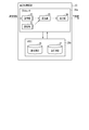
- FIG. 1 is a block diagram illustrating a functional configuration of a blood pressure management device according to an application example.
- FIG. 2 is a schematic view illustrating the configuration of a blood pressure processing system including the blood pressure management device according to the first embodiment.
- FIG. 3 is a block diagram illustrating a hardware configuration of the blood pressure measurement device according to the first embodiment.
- FIG. 4 is a block diagram illustrating a hardware configuration of the mobile terminal according to the first embodiment.
- FIG. 5 is a block diagram illustrating a hardware configuration of the doctor terminal according to the first embodiment.
- FIG. 6 is a block diagram illustrating a hardware configuration of the server according to the first embodiment.
- FIG. 7 is a block diagram illustrating a functional configuration of the blood pressure processing circuit according to the first embodiment.
- FIG. 1 is a block diagram illustrating a functional configuration of a blood pressure management device according to an application example.
- FIG. 2 is a schematic view illustrating the configuration of a blood pressure processing system including the blood pressure management device according to the first embodiment
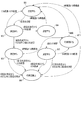
- FIG. 8 is a state transition diagram illustrating the procedure of the representative value calculation process in the blood pressure management device according to the first embodiment.
- FIG. 9 is a diagram illustrating measurement values reflected in the calculation of the representative value in the representative value calculation process in the blood pressure management device according to the first embodiment.
- FIG. 10 is a state transition diagram illustrating the procedure of the representative value calculation process in the blood pressure management device according to the first modification of the first embodiment.
- FIG. 11 is a state transition diagram illustrating the procedure of representative value calculation processing in the blood pressure management device according to the second modification of the first embodiment.
- FIG. 12 is a state transition diagram illustrating the procedure of the representative value calculation process in the blood pressure management device according to the third modification of the first embodiment.
- FIG. 13 is a state transition diagram illustrating a procedure of representative value calculation processing in the blood pressure management device according to the second embodiment.
- FIG. 14 is a flowchart illustrating an example of a procedure of representative value calculation processing in the blood pressure processing circuit according to the third embodiment.
- the blood pressure management device 1 includes an acquisition unit 2, a setting unit 3, a calculation unit 4, and an output unit 5.
- the blood pressure management device 1 executes representative value calculation processing based on the blood pressure processing program.
- the blood pressure processing program is an example of a blood pressure management program.
- the acquisition unit 2 acquires blood pressure measurement information for a specific measurer.
- the measurement information includes a measurement value obtained by measuring blood pressure using a sensor.
- the blood pressure measurement value is associated with the measurement date and time (measurement date and measurement time). Therefore, the measurement information can include the blood pressure measurement value and the measurement date and time.
- the setting unit 3 sets a unit measurement period based on blood pressure fluctuation characteristics.
- the unit measurement period includes a plurality of occasions where one or more measurements are performed.
- the unit measurement period is, for example, a set time for a time zone, a time zone switching time, or the like.
- the set time related to the time zone includes, for example, the start time and end time of the time zone.
- the calculation unit 4 acquires blood pressure measurement information from the acquisition unit 2 and acquires a unit measurement period from the setting unit 3.
- the calculation unit 4 calculates a representative value of blood pressure for each unit measurement period based on the blood pressure measurement value and the unit measurement period.
- the representative value of blood pressure in a specific unit measurement period is calculated using, for example, one or more measurement values in a specific unit measurement period.
- the representative value of the blood pressure in the unit measurement period is, for example, an average value, a median value, or the like of one or more measurement values measured in a specific unit measurement period.
- the output unit 5 outputs the calculated representative value to the outside.
- the calculation unit 4 uses the measurement result obtained by the measurement performed within 10 minutes, A representative value of blood pressure is calculated. Even if the measurement is further performed after the representative value of the blood pressure is calculated in the specific unit measurement period, the calculation unit 4 does not measure the representative value of the blood pressure with respect to the measurement result by the measurement after the representative value of the blood pressure is calculated. Do not reflect on.
- An opportunity represents a series of measurement actions including one or more measurements.
- a series of actions from the start of preparation for blood pressure measurement to the end of a plurality of continuous blood pressure measurements is performed.
- the measurement of the blood pressure “2 times or 3 times” is an example of “the specified number of times of measurement in calculating the representative value of blood pressure”.
- the specified number of measurements is the number of blood pressure measurements recommended for use in calculating the representative value.
- the prescribed number of times of measurement is determined based on blood pressure fluctuation characteristics and the like in guidelines for measuring blood pressure.
- the specified number of measurements is, for example, “1 time”, “2 times”, “2 times or 3 times”, and the like.
- “2” is the minimum specified number
- “3” is the maximum specified number.
- the calculation unit 4 performs the measurement by the first measurement and the measurement by the second measurement. Using the result, a representative value of blood pressure is calculated.
- “when the second measurement is performed after 10 minutes have passed since the first measurement” is “when the first measurement and the second measurement are not performed within the time of one opportunity” It is an example. Even if the first measurement and the second measurement are not performed within the time of one opportunity, the first measurement result and the second measurement result are useful as values used for measuring the representative value. It is known.
- FIG. 2 is a diagram schematically illustrating an example of an application scene of the blood pressure processing system according to the present embodiment.
- the blood pressure processing system according to the present embodiment is a system that calculates a representative value of blood pressure for each unit measurement period using a blood pressure value measured by a measurer, and stores or presents the calculated representative value.
- Blood pressure varies due to various factors such as time, measurement environment, and measurement status.
- the correct measurement method of blood pressure is determined by the guidelines of each country based on the fluctuation characteristics of blood pressure.
- the blood pressure processing system according to the present embodiment is used in an area where it is recommended to calculate a representative value in a specific unit measurement period using two or three measurement results. .
- the blood pressure processing system according to the present embodiment is assumed to be used in, for example, the United States.
- the US hypertension management guidelines recommend that blood pressure be measured at least two times a day and at least twice at each opportunity based on blood pressure fluctuation characteristics and the like. For example, it is preferable to measure blood pressure within one hour after waking up and before going to bed.
- the blood pressure processing system includes a blood pressure measurement device 10 and a portable terminal 30.
- the blood pressure measurement device 10 and the portable terminal 30 are connected by short-range wireless communication or wired communication.
- the blood pressure processing system may further include a doctor terminal 50 and a server 70.
- the portable terminal 30 is connected to each of the doctor terminal 50 and the server 70 via the network NW.
- the blood pressure measurement device 10 can be connected to each of the doctor terminal 50 and the server 70 via the portable terminal 30. That is, the blood pressure measurement device 10 can communicate with each of the doctor terminal 50 and the server 70 via the portable terminal 30.
- the communication between the mobile terminal 30, the doctor terminal 50, and the server 70 can be, for example, communication via the network NW, but is not limited thereto, and short-range wireless communication or wired communication is possible. May be applied.
- the blood pressure measurement device 10 is a device that can be attached to any measurement location (for example, wrist).
- the blood pressure measurement device 10 measures the blood pressure value of the measurer at the measurement location.
- the blood pressure measurement device 10 includes a blood pressure processing circuit 20.
- the blood pressure processing circuit 20 calculates a representative value of blood pressure for each time zone based on the measurement result of the blood pressure value.
- the blood pressure measurement device 10 can transmit blood pressure information including a blood pressure value measurement result and a representative value calculation result to the mobile terminal 30.
- the blood pressure processing circuit 20 is an example of a blood pressure management device. “Time zone” is an example of “unit measurement period”.
- the mobile terminal 30 is, for example, a terminal that can be carried by a measurer.
- the portable terminal 30 receives blood pressure information from the blood pressure measurement device 10.
- the portable terminal 30 transfers the received blood pressure information to the doctor terminal 50 and the server 70.
- the mobile terminal 30 displays diagnostic information and the like received from the doctor terminal 50.
- the doctor terminal 50 is a terminal that can be operated by a doctor, for example.
- the doctor terminal 50 receives blood pressure information from the portable terminal 30.
- the doctor terminal 50 generates diagnostic information about the measurer based on the received blood pressure information and biological information about the measurer.
- the doctor terminal 50 transmits the generated diagnostic information to the mobile terminal 30 and the server 70.
- the server 70 is a server computer that accumulates information transmitted from the mobile terminal 30, the doctor terminal 50, and the like.
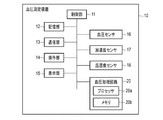
- FIG. 3 is a block diagram illustrating an example of a hardware configuration of the blood pressure measurement device 10 according to the present embodiment.
- the blood pressure measurement device 10 according to the present embodiment includes a control unit 11, a storage unit 12, a communication unit 13, an operation unit 14, a display unit 15, a blood pressure sensor 16, and a blood pressure processing circuit 20.
- the blood pressure measurement device 10 may further include at least one of an acceleration sensor 17 and a temperature / humidity sensor 18.
- the blood pressure processing circuit 20 is an example of a blood pressure management device.
- the blood pressure management device is provided in the blood pressure measurement device 10, but may be provided in any of the mobile terminal 30, the doctor terminal 50, and the server 70.
- the control unit 11 includes a CPU (Central Processing Unit), a RAM (Random Access Memory), a ROM (Read Only Memory), and the like, and controls each component according to information processing.
- the control unit 11 includes a clock (not shown) and has a function of acquiring the current date and time.
- the control unit 11 may have a function of displaying the acquired date and time on the display unit 15.
- the control unit 11 generates blood pressure information, activity information, and environmental information based on the measurement result by the blood pressure sensor 16, the acceleration sensor 17, the temperature / humidity sensor 18, and the calculation result by the blood pressure processing circuit 20.
- the blood pressure information includes, for example, the measurement result of the blood pressure value of the measurer by the blood pressure sensor 16, the calculation result of the representative value of blood pressure by the blood pressure processing circuit 20, and the like.
- the activity information includes the activity amount of the measurer, the number of steps, and the sleep state based on the measurement by the acceleration sensor 17.
- the environmental information includes the temperature around the measurer and the humidity based on the measurement by the temperature / humidity sensor 18.
- Each of blood pressure information, activity information, and environment information is associated with a measurement date based on the current date and time acquired by the clock.
- each of the blood pressure information, the activity information, and the environment information may be further associated with a device ID that uniquely identifies the blood pressure measurement device 10.
- the storage unit 12 is an auxiliary storage device such as a solid state drive, for example.
- the storage unit 12 may be a hard disk drive.
- the storage unit 12 stores a program executed by the control unit 11, blood pressure information, activity information, environment information, and the like.
- the communication unit 13 is a communication interface that manages communication with the mobile terminal 30.
- the communication unit 13 transmits blood pressure information, activity information, environment information, and the like to the mobile terminal 30.
- near field communication such as Bluetooth (registered trademark) can be applied to the communication with the mobile terminal 30 by the communication unit 13, but is not limited thereto.
- the communication by the communication unit 13 may be, for example, communication via a network NW such as a LAN (Local Area Network) or wired communication using a communication cable.
- the operation unit 14 includes, for example, a user interface such as a touch panel and operation buttons.
- the operation unit 14 detects an operation by the measurer via the user interface, and outputs a signal indicating the content of the operation to the control unit 11.
- the display unit 15 includes, for example, a display screen (for example, an LCD (Liquid Crystal Display) or an EL (Electroluminescence) display), an indicator, and the like.
- the display unit 15 displays information according to a signal from the control unit 11 and notifies the measurer.
- the display unit 15 can display blood pressure information, activity information, environment information, and the like stored in the storage unit 12.
- the blood pressure sensor 16 measures the blood pressure value of the measurer.
- the blood pressure value includes, for example, representative indexes such as a maximum blood pressure and a minimum blood pressure.
- representative indexes such as a maximum blood pressure and a minimum blood pressure.
- the blood pressure value is described as being the systolic blood pressure, but the diastolic blood pressure and other indices may be used instead of the systolic blood pressure, or a plurality of these indices may be used in combination. Good.
- the blood pressure sensor 16 may be, for example, a continuous measurement type capable of measuring the blood pressure of the measurer for each beat (continuous) of the heartbeat, or a non-continuous measurement type capable of measuring with a spot (non-continuous) at a predetermined time. But you can.
- the continuous measurement type blood pressure sensor 16 includes, for example, a method of continuously measuring a blood pressure of a measurer based on a pulse wave transmission time (PTT; Pulse Transmit Time) and a blood pressure continuously based on a pressure pulse wave.
- PTT Pulse Transmit Time
- a measuring method (tonometry method) or the like is applicable.
- the method of continuously measuring blood pressure is not limited to the above-described example, and a method of detecting a pulse wave using a light emitting element can be appropriately applied.
- a technique (oscillometric method) for detecting a pulse wave by compressing a blood vessel using a cuff as a pressure sensor can be applied to the non-continuous measurement type blood pressure sensor 16.
- the acceleration sensor 17 detects the measurement person's acceleration generated at the place where the blood pressure measurement device 10 is mounted as a set of three-axis components.
- the acceleration sensor 17 may further include a gyro sensor, and may further detect the angular velocity as a set of three-axis components in addition to the acceleration.
- the temperature and humidity sensor 18 measures the temperature and humidity around the measurer.
- the blood pressure processing circuit 20 uses the blood pressure information generated from the measurement result of the blood pressure sensor 16 by the control unit 11 to calculate a representative value of blood pressure for each time zone.
- the blood pressure processing circuit 20 may be provided in any of the blood pressure measurement device 10, the mobile terminal 30, the doctor terminal 50, and the server 70.
- the blood pressure processing circuit 20 includes, for example, a processor 20a and a memory 20b.
- the blood pressure processing circuit 20 implements various operation controls, data processing, and the like by the processor 20a executing a program stored in the memory 20b.
- the blood pressure processing circuit 20 has a clock (not shown) and can measure the current date and time.
- the processor 20a is, for example, a CPU including an arithmetic circuit or an MPU (Micro Processing Unit).
- the processor 20a can execute control of each unit and data processing by executing a program stored in the memory 20b or the storage unit 12.
- the memory 20b includes, for example, a nonvolatile memory that stores a program executed by the processor 20a and a volatile memory such as a RAM that is used as a working memory.
- the blood pressure processing circuit 20 executes representative value calculation processing based on the blood pressure processing program.
- the blood pressure processing program is an example of a blood pressure management program.
- the representative value calculation process by the blood pressure processing circuit 20 will be described later.
- the blood pressure processing program is a program for causing the blood pressure processing circuit 20 to execute representative value calculation processing.
- the blood pressure processing program may be stored in the memory 20b or may be stored in the storage unit 12.
- control unit 11 may function as the blood pressure processing circuit 20. That is, the control unit 11 may also serve as the blood pressure processing circuit 20.
- the CPU of the control unit 11 becomes the processor 20a of the blood pressure processing circuit 20
- the ROM of the control unit 11 becomes a non-volatile memory of the memory 20b of the blood pressure processing circuit 20
- the RAM of the control unit 11 becomes the memory 20b of the blood pressure processing circuit 20. Volatile memory.
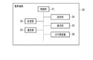
- FIG. 4 is a block diagram illustrating an example of a hardware configuration of the mobile terminal 30 according to the present embodiment.
- the mobile terminal 30 according to the present embodiment includes a control unit 31, a storage unit 32, a communication unit 33, an operation unit 34, a display unit 35, and a GPS (Global Positioning System) receiver 36.
- a GPS Global Positioning System
- the control unit 31 and the storage unit 32 are the same as the control unit 11 and the storage unit 12 of the blood pressure measurement device 10, respectively.
- the storage unit 32 of the portable terminal 30 stores information received from the blood pressure measurement device 10 and position information generated by the GPS receiver 36.
- the information received from the blood pressure measurement device 10 includes blood pressure information, activity information, environmental information, and the like.
- the communication unit 33 is a communication interface that controls communication with the blood pressure measurement device 10, the doctor terminal 50, and the server 70.
- the communication unit 33 receives, for example, blood pressure information, activity information, environment information, and the like from the blood pressure measurement device 10.
- the communication unit 33 transmits blood pressure information, activity information, environment information, position information, and the like to the doctor terminal 50 and the server 70.
- the operation unit 34 and the display unit 35 are the same as the operation unit 14 and the display unit 15 of the blood pressure measurement device 10, respectively.
- the GPS receiver 36 measures the position of the mobile terminal 30 and generates position information.
- the position information includes, for example, the positioning date and time, and the latitude and longitude of the mobile terminal 30 at the positioning date and time.
- the positioning by the GPS receiver 36 can be performed in synchronization with the measurement of the blood pressure sensor 16 of the blood pressure measurement device 10, for example.
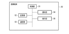
- FIG. 5 is a block diagram illustrating an example of a hardware configuration of the doctor terminal 50 according to the present embodiment.
- the doctor terminal 50 according to the present embodiment includes a control unit 51, a storage unit 52, a communication unit 53, an operation unit 54, and a display unit 55.
- the control unit 51 and the storage unit 52 are the same as the control unit 11 and the storage unit 12 of the blood pressure measurement device 10, respectively.
- the control unit 51 of the doctor terminal 50 generates biological information related to the measurer, diagnostic information related to the measurer, and the like.
- the storage unit 52 of the doctor terminal 50 temporarily stores information transferred from the portable terminal 30, biological information regarding the measurer, diagnostic information regarding the measurer, and the like.
- the communication unit 53 is a communication interface that manages communication with the mobile terminal 30 and the server 70.
- the communication unit 53 receives, for example, blood pressure information, activity information, environment information, and the like from the mobile terminal 30.
- the communication unit 53 transmits biological information about the measurer, diagnostic information about the measurer, and the like to the mobile terminal 30 and the server 70.
- the operation unit 54 and the display unit 55 are the same as the operation unit 14 and the display unit 15 of the blood pressure measurement device 10, respectively.
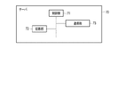
- FIG. 6 is a block diagram illustrating an example of a hardware configuration of the server 70 according to the present embodiment.
- the server 70 according to the present embodiment includes a control unit 51, a storage unit 52, and a communication unit 53.
- the control unit 71 and the storage unit 72 are the same as the control unit 11 and the storage unit 12 of the blood pressure measurement device 10, respectively.
- the storage unit 72 of the server 70 stores information transmitted from the mobile terminal 30 and the doctor terminal 50.
- the communication unit 73 is a communication interface that manages communication with the mobile terminal 30 and the doctor terminal 50.
- the communication unit 73 receives, for example, blood pressure information, activity information, environment information, and the like from the mobile terminal 30.
- the communication unit 73 receives blood pressure information, activity information, environment information, and the like from the doctor terminal 50.
- the communication unit 73 receives biological information related to the measurer, diagnostic information related to the measurer, and the like from the doctor terminal 50.
- the communication unit 73 transmits the information stored in the storage unit 72 to the portable terminal 30 and the doctor terminal 50.
- FIG. 7 is a block diagram schematically illustrating an example of a functional configuration of the blood pressure processing circuit 20 of the blood pressure processing system according to the present embodiment.
- the processor 20a of the blood pressure processing circuit 20 expands the blood pressure processing program stored in the nonvolatile memory of the memory 20b in the volatile memory of the memory 20b.
- the processor 20a functions as the acquisition unit 21, the setting unit 22, the calculation unit 23, and the output unit 24 by interpreting and executing the blood pressure processing program developed in the volatile memory.
- the volatile memory of the memory 20b temporarily stores setting information 27, blood pressure information 26, blood pressure representative values, and the like.
- the blood pressure information 26 includes a blood pressure measurement value and measurement date and time that are measurement information from the control unit 11, a blood pressure representative value calculated by the calculation unit 23, and the like.
- the setting information 27 includes information related to the unit measurement period set by the setting unit 22.
- the acquisition unit 21 acquires measurement information, stores the acquired measurement information in the memory 20b as blood pressure information 26, and transmits the measurement information to the calculation unit 23.
- the setting unit 22 sets a unit measurement period based on blood pressure fluctuation characteristics.
- the unit measurement period may be stored in advance in the memory 20b or the storage unit 12, or may be input in the operation unit 14.
- the unit measurement period includes a plurality of opportunities.
- the unit measurement period includes, for example, a set time for each time zone.
- the set time in each time zone includes, for example, a set time in the morning time zone and a set time in the night time zone.
- the setting unit 22 can set each unit measurement period by setting the switching time of the unit measurement period.
- the setting unit 22 stores the set switching time in the memory 20 b as setting information 27 and transmits it to the calculation unit 23.
- the calculation unit 23 calculates a representative value of blood pressure for each time zone based on the blood pressure information 26 and the setting information 27.
- the representative value calculation process by the setting unit 22 and the calculation unit 23 will be described later.
- the representative value of blood pressure in a specific unit measurement period is calculated using, for example, a plurality of measurement values measured within a specific unit measurement period.
- the representative value of blood pressure in a specific unit measurement period is, for example, an average value, a median value, or the like of a plurality of measurement values measured during the unit measurement period.
- the output unit 24 acquires the representative value of the blood pressure calculated by the calculation unit 23.
- the output unit 24 outputs the acquired representative value of blood pressure to the storage unit 12 or the like.
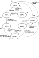
- FIG. 8 is a diagram schematically illustrating an example of a procedure of representative value calculation processing by the setting unit 22 and the calculation unit 23 in the blood pressure processing circuit 20 according to the present embodiment. .
- the setting unit 22 sets the time from 0 o'clock to 12:00 as the morning time zone and sets the time from 12 o'clock to 24 o'clock (0 o'clock) as the night time in the unit measurement period setting. It is set as a belt. In this case, the setting unit 22 sets 0:00 and 12:00 as time zone switching times.
- the setting unit 22 divides one day (for example, 24 hours from a specific time to the same time on the next day) into a plurality of unit measurement periods by setting a plurality of unit measurement periods.
- the morning time zone is an example of a first unit measurement period, for example
- the night time zone is an example of a second unit measurement period, for example.
- the calculation unit 23 In the representative value calculation process in a specific unit measurement period, the calculation unit 23 first enters the first state M1 at the start time of the unit measurement period. In the first state M1, the calculation unit 23 stands by in the first state M1 until measurement information is acquired by the acquisition unit 21.
- the processor 20a transitions from the first state M1 to the second state M2.
- the calculation unit 23 stores the acquired measurement information in the memory 20b as the first measurement information in a specific time zone.
- the first measurement information is a measurement result obtained by the first measurement in a specific time zone.
- the first measurement information includes a first measurement value and a first measurement time.
- a 1st measured value is a measured value by the 1st measurement in a specific time slot
- the first measurement time is the measurement time of the first measurement in a specific time zone.
- the processor 20a transitions from the second state M2 to the third state M3.
- the calculation unit 23 stores the acquired measurement information in the memory 20b as the second measurement information in the specific time zone.
- the second measurement information is a measurement result obtained by the second measurement in a specific time zone.
- the second measurement information includes a second measurement value and a second measurement time.
- a 2nd measured value is a measured value by the 2nd measurement in a specific time slot
- the second measurement time is the measurement time of the second measurement in a specific time zone.
- the difference between the first measurement time and the second measurement time is within 10 minutes. “10 minutes” is an example of “representative time required for one-hour measurement behavior”.
- the calculation unit 23 transitions to the fourth state M4 when 10 minutes have elapsed from the first measurement time in a state where the measurement information is not acquired by the acquisition unit 21.
- the calculation unit 23 changes from the second state M2 to the first state. Transition to M1. At this time, the calculation unit 23 determines that the time zone has been switched. “0:00” and “12:00” are examples of “time zone switching time”.
- the calculation unit 23 ends the night time zone. Judge that the morning time has started.
- the calculation unit 23 ends the morning time zone. Judge that the night time has started.
- the processor 20a transitions from the third state M3 to the sixth state M6.
- the calculation unit 23 stores the acquired measurement information in the memory 20b as the third measurement information in the specific time zone.
- the third measurement information is a measurement result obtained by the third measurement in a specific time zone.
- the third measurement information includes a third measurement value and a third measurement time.
- a 3rd measured value is a measured value by the 3rd measurement in a specific time slot
- the third measurement time is the measurement time of the third measurement in a specific time zone. The difference between the first measurement time and the third measurement time is within 10 minutes.
- the calculation unit 23 transitions to the sixth state M6 in a state where the first measurement information, the second measurement information, and the third measurement information in the specific time zone are stored in the memory 20b.
- the calculation unit 23 transitions from the third state M3 to the sixth state M6. At this time, the calculation unit 23 transitions to the sixth state M6 in a state where the first measurement information and the second measurement information are stored in the memory 20b.
- the calculation unit 23 changes from the third state M3 to the seventh state. Transition to M7. At this time, the calculation unit 23 determines that the specific time zone has been switched to the next time zone. The calculation unit 23 transitions to the seventh state M7 in a state where the first measurement information and the second measurement information in a specific time zone are stored in the memory 20b.
- the calculation unit 23 transitions from the fourth state M4 to the first state M1 at 0:00 or 12:00. At this time, the calculation unit 23 determines that the specific time zone has been switched to the next time zone.
- the processor 20a transitions from the fourth state M4 to the fifth state M5.
- the calculation unit 23 stores the acquired measurement information in the memory 20b as the second measurement information in the specific time zone. The difference between the first measurement time and the second measurement time is greater than 10 minutes.
- the processor 20a transitions from the fifth state M5 to the sixth state M6.
- the calculation unit 23 stores the acquired measurement information in the memory 20b as the third measurement information in the specific time zone.
- the difference between the second measurement time and the third measurement time is within 10 minutes.
- the calculation unit 23 transitions to the sixth state M6 in a state where the first measurement information, the second measurement information, and the third measurement information in the specific time zone are stored in the memory 20b.
- the calculation unit 23 transitions from the fifth state M5 to the sixth state M6.
- the calculation unit 23 transitions to the sixth state M6 in a state where the first measurement information and the second measurement information in a specific time zone are stored in the memory 20b.
- the calculation unit 23 changes from the fifth state M5 to the seventh state. Transition to M7. At this time, the calculation unit 23 determines that the specific time zone has been switched to the next time zone. The calculation unit 23 transitions to the seventh state M7 in a state where the first measurement information and the second measurement information in a specific time zone are stored in the memory 20b.
- the calculation unit 23 calculates a representative value of blood pressure in a specific time zone using the measurement information stored in the memory 20b.
- the calculation unit 23 stores the calculated representative value in the memory 20b and transmits it to the output unit 24.
- the calculation unit 23 determines that the specific time zone has been switched to the next time zone, and transitions from the sixth state M6 to the first state M1. That is, after the representative value is calculated in the sixth state M6, even if measurement information is acquired by the acquisition unit 21, it is not used for calculating the representative value.
- the calculation unit 23 calculates a representative value of blood pressure in a specific time zone using the measurement information stored in the memory 20b.
- the calculation unit 23 stores the calculated representative value in the memory 20b and transmits it to the output unit 24.
- the calculation of the representative value of blood pressure in the seventh state M7 is performed, for example, in the same manner as the calculation of the representative value of blood pressure in the sixth state M6.
- the calculation unit 23 immediately transitions to the first state M1 when the calculation of the representative value is completed.
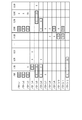
- FIG. 9 shows an example of measurement information employed in the representative value calculation process by the blood pressure processing circuit 20 according to the present embodiment.
- the fact that the blood pressure has been measured is indicated by a cross.
- a plurality of X marks are adjacent to each other, it indicates that a plurality of measurements were performed within 10 minutes.
- “Within 10 minutes” is an example of “within the time of one opportunity”.
- One opportunity is, for example, generally the time required for one action.
- One opportunity is, for example, 10 minutes.
- pattern 1 indicates that three measurements were performed within 10 minutes in the time from 07:00 to 07:30.
- the X marks are not adjacent to each other, it indicates that the corresponding measurement times are separated by 10 minutes or more.
- FIG. 9 it is assumed that no measurement is performed before 07:00 and after 14:00.
- the measurement result used for calculating the representative value of the blood pressure among the measurement results is shown surrounded by a bold line.
- pattern 1 blood pressure is measured four times in the night time zone, and the measurement results from the first to third measurements are used to calculate the representative value of blood pressure and reflected in the representative value of blood pressure. Is done.
- blood pressure is measured once in the morning time zone.
- the first measurement is performed during the time from 07:00 to 07:30.
- the calculation unit 23 transitions in the order of the first state M1, the second state M2, and the first state M1. Therefore, in the morning time zone of the pattern 7, the calculation unit 23 does not transition to the sixth state M6 or the seventh state M7, and thus the representative value is not calculated.
- the present embodiment is assumed to be used in an area where it is recommended to calculate a representative value in a specific unit measurement period using two or more measurement results.
- the representative value of the blood pressure is not calculated. Therefore, it is possible to prevent a representative value of blood pressure from being calculated using a measurement result that does not satisfy the specified number. Thereby, it is possible to obtain a representative value that satisfies the definition of the number of times of measurement for the blood pressure value.
- blood pressure is measured four times during the night time zone.
- the measurement from the first time to the third time is performed in the time from 12:00 to 12:30.
- the measurement from the first time to the third time is performed within 10 minutes.
- the fourth measurement is performed at a time from 13:00 to 13:30.
- the fourth measurement is performed after 10 minutes or more have passed since the first measurement.
- the calculation unit 23 transitions in the order of the first state M1, the second state M2, the third state M3, and the sixth state M6.
- the measurement results by the first to third measurements are reflected in the representative value of the blood pressure in the morning time zone.
- the calculation unit 23 starts calculating the representative value of blood pressure. For this reason, even if the fourth measurement is performed in the sixth state M6, the measurement value is not reflected in the representative value of the blood pressure.
- the present embodiment is assumed to be used in an area where it is recommended to calculate a representative value in a specific unit measurement period using two or more measurement results. For this reason, in the calculation of the representative value of the blood pressure for a specific time zone, it is sufficient if the measurement results of three times are reflected. According to the present embodiment, when the blood pressure measurement is performed four or more times in a specific time zone, the measurement results after the fourth time are not reflected in the representative value. Thereby, the calculation of the representative value of blood pressure can be performed efficiently.
- blood pressure is measured three times in the night time zone.
- the first measurement and the second measurement are performed at a time from 12:00 to 12:30.
- the first and second measurements are made within 10 minutes.
- the third measurement is performed in the time from 13:00 to 13:30.
- the third measurement is performed after 10 minutes or more have passed since the second measurement.
- the calculation unit 23 transitions in the order of the first state M1, the second state M2, the third state M3, and the sixth state M6.
- the measurement results in the first and second measurements are reflected in the representative value of the blood pressure in the night time zone.
- the calculation unit 23 starts calculating the representative value of blood pressure when 10 minutes have elapsed since the first measurement. For this reason, even if the third measurement is performed in the sixth state M6, the measurement value is not reflected in the representative value of the blood pressure.
- the present embodiment is assumed to be used in an area where it is recommended to calculate a representative value in a specific unit measurement period using two or more measurement results.
- a measurement result obtained by measurement after 10 minutes or more from the first measurement may not be suitable for calculating the representative value.
- the present embodiment when a measurement value is obtained twice or more in a specific time zone and measurement is performed after 10 minutes or more have passed since the first measurement, the first measurement is performed. Measurement results obtained after 10 minutes or more have passed are not reflected in the representative values. As a result, for the blood pressure value, an appropriate representative value that satisfies the definition of the number of measurements and that does not reflect unnecessary measurement results can be obtained.
- blood pressure is measured twice in the night time zone.
- the first measurement is performed at a time from 12:00 to 12:30.
- the second measurement is performed at a time from 12:30 to 13:00.
- the second measurement is performed after 10 minutes or more have passed since the first measurement.
- the calculation unit 23 transitions in the order of the first state M1, the second state M2, the fourth state M4, the fifth state M5, and the sixth state M6.
- the sixth state M6 the measurement results in the first and second measurements are reflected in the representative value of blood pressure in the night time zone.
- blood pressure is measured three times in the morning time zone.
- the first measurement is performed during the time from 07:00 to 07:30.
- the second measurement is performed from 07:30 to 08:00.
- the second measurement is performed after 10 minutes or more have passed since the first measurement.
- the third measurement is performed during the period from 08:00 to 08:30.
- the third measurement is performed after 10 minutes or more have passed since the second measurement.
- the calculation unit 23 transitions in the order of the first state M1, the second state M2, the fourth state M4, the fifth state M5, and the sixth state M6.
- the sixth state M6 the measurement results in the first and second measurements are reflected in the representative value of blood pressure in the morning time zone.
- the calculation unit 23 starts calculating the representative value of blood pressure when 10 minutes have elapsed since the second measurement. For this reason, even if the third measurement is performed in the sixth state M6, the measurement value is not reflected in the representative value of the blood pressure.
- the second measurement may be performed after 10 minutes or more have elapsed since the first measurement. .
- the first measurement result and the second measurement result are performed within the unit measurement period, they are useful for calculating the representative value.
- the second measurement is not performed on the same occasion as the first measurement, the first measurement result and the second measurement result are useful for calculating the representative value of blood pressure.
- the blood pressure representative value reflecting the measurement result and the second measurement result may not be calculated.
- the representative value of blood pressure is calculated using the second measurement result and the second measurement result. For this reason, even when the second measurement is performed after 10 minutes or more have passed since the first measurement, the representative value of blood pressure that satisfies the specified number and appropriately reflects the useful measurement result Can be obtained.
- blood pressure is measured three times in the morning time zone.
- the first measurement is performed during the time from 07:00 to 07:30.
- the second and third measurements are performed from 07:30 to 08:00.
- the second measurement is performed after 10 minutes or more have passed since the first measurement.
- the second and third measurements are made within 10 minutes.
- the calculation unit 23 transitions in the order of the first state M1, the second state M2, the fourth state M4, the fifth state M5, and the sixth state M6.
- the sixth state M6 the measurement results in the first to third measurements are reflected in the representative value of blood pressure in the morning time zone.
- blood pressure is measured four times during the night time zone.
- the first measurement is performed at a time from 12:30 to 13:00.
- the second and third measurements are performed from 13:00 to 13:30.
- the second measurement is performed after 10 minutes or more have passed since the first measurement.
- the second and third measurements are made within 10 minutes.
- the 4th measurement is performed in the time from 13:30 to 14:00.
- the fourth measurement is performed after 10 minutes or more have passed since the third measurement.
- the calculation unit 23 transitions in the order of the first state M1, the second state M2, the fourth state M4, the fifth state M5, and the sixth state M6.
- the sixth state M6 the measurement results in the first to third measurements are reflected in the representative value of the blood pressure for the night time zone.
- the calculation unit 23 starts calculating the representative value of blood pressure. For this reason, even if the fourth measurement is performed in the sixth state M6, the measurement value is not reflected in the representative value of the blood pressure.
- the second measurement is performed after 10 minutes or more have passed since the first measurement
- the third measurement may be performed within 10 minutes from the first measurement.
- the measurement results from the first to third measurements are useful for calculating the representative value of blood pressure.
- the measurement result from the third measurement to the third measurement may not be appropriately reflected in the representative value of blood pressure.
- the second measurement is performed after 10 minutes or more have passed since the first measurement, and the third measurement is performed within 10 minutes from the second measurement.
- a representative value of blood pressure is calculated using the measurement results from the first to third measurements. For this reason, a representative value of blood pressure in which useful measurement results are more appropriately reflected can be obtained.
- the measurer when the measurer has a lifestyle as shown in the pattern 1, for example, the measurer measures the blood pressure before going to bed between 07:00 and 07:30, and 12:00 to 12:30. During this period, the blood pressure value after waking up is measured. In this case, the measurement result by the measurement between 12:00 and 12:30 is useful for calculating the representative value of blood pressure as the blood pressure value after waking up.
- the time from 0:00 to 12:00 is set as a morning time zone, and the time from 12:00 to 24:00 is set as a night time zone. Therefore, the measurement result by the measurement between 07:00 and 07:30 is reflected in the calculation of the representative value of the first unit measurement period, and the measurement result by the measurement between 12:00 and 12:30 This is reflected in the calculation of the representative value for the 2-unit measurement period. Therefore, even when the measurer has a lifestyle as shown in Pattern 1, a useful value such as a blood pressure value after waking up is reflected in the representative value of blood pressure.
- a time that does not correspond to either the morning time zone or the night time zone is not provided. That is, there is no time in one day that does not correspond to any unit measurement period. Therefore, all the times in one day are included in any unit measurement period. For this reason, according to this embodiment, even if a shift worker whose life time zone changes or a person living across multiple standard times is a measurer, a representative value of blood pressure in which useful measurement results are appropriately reflected Can be calculated.
- the calculation unit 23 transitions to the third state M3 based on the acquisition of the second measurement information in the second state M2. Further, the calculation unit 23 transitions to the fifth state M5 based on the acquisition of the second measurement information in the fourth state M4. And in the 3rd state M3 and the 5th state M5, acquisition of the 3rd measurement information is waited. Then, in the third state M3 and the fifth state M5, regardless of whether or not the third measurement information is acquired, the state transitions to either the sixth state M6 or the seventh state M7 within 10 minutes from the second measurement time. To do. For this reason, from the time of acquisition of the second measurement information, the state of waiting for acquisition of the third measurement information is completed within 10 minutes.
- the calculation unit 23 transitions to the second state M2 based on the acquisition of the first measurement information in the first state M1. And in 2nd state M2, acquisition of 2nd measurement information is waited. And in 2nd state M2, when 2nd measurement information is not acquired, acquisition of 2nd measurement information is waited until it becomes time switching time. For this reason, the state which waits for acquisition of the 2nd measurement information from the time of acquisition of the 1st measurement information can be maintained for several hours, for example. Therefore, the maximum time from the acquisition of the first measurement information to the end of the state of waiting for the acquisition of the second measurement information is the end of the state of waiting for the acquisition of the third measurement information from the acquisition of the second measurement information. Longer than the maximum time to do.
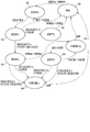
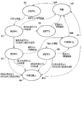
- FIG. 10 is a diagram schematically illustrating an example of a procedure of representative value calculation processing by the setting unit 22 and the calculation unit 23 in the blood pressure processing circuit 20 according to the present modification.
- the setting unit 22 sets the time from 4 o'clock to 11 o'clock as the morning time zone and sets the time from 19 o'clock to 2 o'clock as the night time zone in the unit measurement period setting. ing.
- the setting unit 22 sets 4 o'clock as the start time of the morning time zone, and sets 11:00 as the end time of the morning time zone.
- the setting unit 22 sets 19:00 as the start time of the night time zone and sets 2 o'clock as the end time of the night time zone.
- the setting unit 22 sets 4 o'clock, 11 o'clock, 19 o'clock, and 2 o'clock as time zone switching times.
- the morning time zone is an example of a first unit measurement period, for example
- the night time zone is an example of a second unit measurement period, for example.
- the measurement information is not acquired by the acquisition unit 21, and within 10 minutes from the first measurement time, 2:00 or At 11 o'clock, the calculation unit 23 transitions from the second state M2 to the eighth state M8. At this time, the calculation unit 23 determines that the morning time zone or the night time zone has ended.
- the calculation unit 23 changes from the third state M3 to the seventh state. Transition to M7. At this time, the calculation unit 23 determines that the morning time zone or the night time zone has started. The calculation unit 23 transitions to the seventh state M7 in a state where the first measurement information and the second measurement information in a specific time zone are stored in the memory 20b.
- the calculation unit 23 transitions from the fourth state M4 to the eighth state M8. At this time, the calculation unit 23 determines that the morning time zone or the night time zone has ended.
- the calculation unit 23 changes from the fifth state M5 to the seventh state. Transition to M7. At this time, the calculation unit 23 determines that the morning time zone or the night time zone has ended. The calculation unit 23 transitions to the seventh state M7 in a state where the first measurement information and the second measurement information in a specific time zone are stored in the memory 20b.
- the calculation unit 23 transitions to the eighth state M8.
- the calculation unit 23 waits until 4 o'clock or 19 o'clock. At 4 o'clock or 19 o'clock, the calculation unit 23 transitions from the eighth state M8 to the first state M1. At this time, the calculation unit 23 determines that the morning time zone or the night time zone has started.
- the end time of the night time zone is set to 2 o'clock. For this reason, even when blood pressure is measured in the night time zone from 0:00 to 2 o'clock the next day, the blood pressure in the night time zone that continues from the previous day is measured as the measurement value in the night time zone. Is used to calculate the representative value. Thereby, for example, even if it is a measurer who measures the blood pressure before going to bed in the night time zone from midnight to 2 o'clock, the measurement information is appropriately reflected in the representative value. By appropriately setting the unit measurement period according to the lifestyle, culture, etc. of the measurer as in this modification, a more accurate representative value of blood pressure can be obtained.
- FIG. 11 is a diagram schematically illustrating an example of a procedure of representative value calculation processing by the setting unit 22 and the calculation unit 23 in the blood pressure processing circuit 20 according to the present modification.
- the setting unit 22 sets the time zone switching time based on the measurement information in setting the unit measurement period.
- the setting unit 22 sets the time 6 hours after the first measurement in the specific time zone as the end time of the specific time zone.
- the calculation unit 23 determines that the specific time zone has ended and has switched to the next time zone.
- the specific time zone is an example of a first unit measurement period
- the next time zone is an example of a second unit measurement period.
- the calculation unit 23 determines that the specific time period has ended and has switched to the next time period.
- the calculation unit 23 causes the fifth state M5 to To 7th state M7. At this time, the calculation unit 23 determines that the time zone has been switched. The calculation unit 23 transitions to the seventh state M7 in a state where the first measurement information and the second measurement information in a specific time zone are stored in the memory 20b.
- the calculation unit 23 transitions to the first state M1. At this time, the calculation unit 23 determines that the time zone has been switched.
- an appropriate representative value may not be calculated when the lifestyle of the measurer changes from day to day. For example, when the time from 5 o'clock to 14 o'clock is set as a morning time zone, the measurer measures blood pressure before going to bed from 6 o'clock and measures blood pressure after waking up from 13 o'clock In this case, both the measurement result from 6 o'clock and the measurement result from 13 o'clock are processed as measurement results in the morning time zone. In this case, the measurement result at 13:00 may not be reflected in the representative value as the measurement result after getting up.
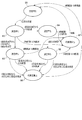
- FIG. 12 is a diagram schematically illustrating an example of a procedure of representative value calculation processing by the setting unit 22 and the calculation unit 23 in the blood pressure processing circuit 20 according to the present modification.
- the acquisition unit 21 acquires the sleep information of the measurer in addition to the measurement information of the measurer.
- the acquisition part 21 can acquire a sleep state from the control part 11, and can acquire sleep information based on the sleep state.
- the control unit 11 detects the sleep state based on a measurement result obtained by the acceleration sensor 17 or another sensor added separately.
- the sleep information may be simply generated based on the activation state and the end state of the alarm application or the like of the mobile terminal 30.
- the sleep information includes, for example, the measurement person's sleep start time and wake-up time (sleep end time).
- the setting unit 22 sets the time zone switching time based on the sleep information in the setting of the unit measurement period.
- the setting unit 22 sets a time one hour after the wake-up time as the end time of the specific time zone.
- the calculation unit 23 determines that the specific time period has ended based on the end time of the specific time period.
- the specific time zone is an example of a first unit measurement period.
- the measurement information is not acquired by the acquisition unit 21, and within 10 minutes from the first measurement time,
- the calculation unit 23 transitions from the second state M2 to the eighth state M8. At this time, the calculation unit 23 determines that the morning time period has ended.
- the calculation unit 23 starts from the third state M3. Transition to 7-state M7. At this time, the calculation unit 23 determines that the morning time period has ended. The calculation unit 23 transitions to the seventh state M7 in a state where the first measurement information and the second measurement information in a specific time zone are stored in the memory 20b.
- the calculation unit 23 transitions from the fourth state M4 to the eighth state M8. At this time, the calculation unit 23 determines that the morning time period has ended.
- the calculation unit 23 changes from the fifth state M5 to the fifth state M5. Transition to 7-state M7. At this time, the calculation unit 23 determines that the morning time period has ended. The calculation unit 23 transitions to the seventh state M7 in a state where the first measurement information and the second measurement information in a specific time zone are stored in the memory 20b.
- the calculation unit 23 transitions to the eighth state M8. At this time, the calculation unit 23 determines that the morning time period has ended.
- the calculation unit 23 determines whether the measurer has woken up based on the sleep information acquired by the acquisition unit 21. When it is determined that the measurer has woken up in the eighth state M8, the calculation unit 23 transitions from the eighth state M8 to the first state M1.
- the wake-up time is acquired, and based on the wake-up time, it is determined that the specific unit measurement period has ended. For this reason, in this modification, by setting the unit measurement period based on the wake-up time, useful measurement results such as measured values after wake-up can be easily obtained even when the lifestyle of the measurer is not constant. Can be identified. This makes it possible to calculate a representative value of blood pressure that appropriately reflects a useful measurement result such as a measurement value after waking up.
- a second unit measurement period may be provided in addition to the first unit measurement period.
- the time 6 hours after the wake-up time is set as the start time of the second unit measurement period
- the sleep start time is set as the end time of the second unit measurement period.
- a time 6 hours after the first measurement after getting up may be set as the start time of the second unit measurement period.
- the first unit measurement period from the wake-up time to 12 hours is set as the second unit measurement period after 12 hours from the wake-up time, etc. You may combine 1st Embodiment and each modification arbitrarily.
- Second Embodiment A second embodiment of the blood pressure management device according to the application example described above will be described below.
- a blood pressure processing system including a blood pressure measurement device as an example of a blood pressure management device will be described.
- the same reference numerals are used for the same components as those in the first embodiment, and the description of the same points as in the first embodiment is omitted as appropriate.
- the blood pressure processing system is a system that calculates a representative value of blood pressure for each unit measurement period using a blood pressure value measured by a measurer, and stores or presents the calculated representative value.
- the blood pressure processing system according to the present embodiment is assumed to be used in an area where it is recommended to calculate a representative value in a specific unit measurement period using the measurement results of 1 to 3 times. .
- the blood pressure processing system according to the present embodiment is assumed to be used in, for example, Japan.
- FIG. 13 is a diagram schematically illustrating an example of a procedure of representative value calculation processing by the setting unit 22 and the calculation unit 23 in the blood pressure processing circuit 20 according to the present embodiment.
- the calculation unit 23 changes to the second state. Transition from M2 to the seventh state M7. At this time, the calculation unit 23 determines that the time zone has been switched.
- the calculation unit 23 transitions from the fourth state M4 to the seventh state M7 at 0:00 or 12:00. At this time, the calculation unit 23 determines that the time zone has been switched.
- blood pressure is measured once in the morning time zone.
- the first measurement is performed during the time from 07:00 to 07:30.
- the calculation unit 23 transitions in the order of the first state M1, the second state M2, and the seventh state M7.
- the measurement result by the first measurement is reflected in the representative value of the blood pressure in the morning time zone.
- this embodiment is assumed to be used in an area where it is recommended to calculate a representative value in a specific unit measurement period using one or more measurement results.
- the blood pressure representative value is calculated even when the blood pressure measurement is performed only once in a specific unit measurement period. Thereby, the representative value according to the regulation of the number of measurements can be obtained for the blood pressure value.
- the processor 20a calculates a representative value of blood pressure for a specific unit measurement period using the stored past measurement results. For example, the processor 20a starts the representative value calculation process for a specific unit measurement period based on the transmission of the instruction to start the representative value calculation process. At this time, an instruction to start representative value calculation is transmitted from the control unit 11 based on, for example, an operation input from the operation unit 14. The specific unit measurement period is input through the operation unit 14, for example.
- the processor 20a may periodically perform the representative value calculation process.
- the representative value calculation process by the processor 20a is performed at an interval of once a day, for example.
- the processor 20a acquires measurement information for one day from the previous representative value calculation process to the present, and performs the representative value calculation process for each unit measurement period within this period.
- the representative value calculation process may be performed at an interval of once a week, for example.
- FIG. 14 is a flowchart showing an example of a procedure of representative value calculation processing in the blood pressure processing circuit 20 according to the present embodiment.
- the processor 20a first acquires setting information and measurement information (S101).
- the acquired information is stored in the memory 20b, for example.
- the measurement information includes one or more measurement results.
- the measurement result includes a measurement value and a measurement time.
- the setting information includes a start time and an end time for a specific unit measurement period.
- the processor 20a extracts the measurement result within the specific unit measurement period based on the measurement time of each measurement result and the setting information about the specific unit measurement period (S102). At this time, the processor 20a determines whether or not each measurement result is a measurement result in a specific unit measurement period by determining whether or not the measurement time is included in the specific unit measurement period for each measurement result. Judging.
- the processor 20a determines whether or not the number of measurement results in a specific unit measurement period is three or more (S103). Thus, the processor 20a determines whether or not the number of measurements in the unit measurement period is three or more.
- the processor 20a determines that the number of measurements in the unit measurement period is 2 or less. In this case, the processor 20a determines whether or not the number of measurement results in the specific unit measurement period is two (S104).
- the processor 20a determines that the number of measurements in the unit measurement period is 1 or 0. In this case, the processor 20a determines that the number of measurements in the unit measurement period does not satisfy the specified number, and does not calculate a representative value of blood pressure (S105).
- the processor 20a determines that the number of measurements in the unit measurement period is two. In this case, the processor 20a specifies whether each measurement result in the specific unit measurement period is the first measurement result or the second measurement result based on the measurement time. The first measurement result includes the first measurement value and the first measurement time, and the second measurement result includes the second measurement value and the second measurement time. Then, the processor 20a calculates a representative value of blood pressure using the first measurement value and the second measurement value (S106).
- the processor 20a determines that the number of measurements in the unit measurement period is 3 or more. In this case, the processor 20a specifies the first measurement result, the second measurement result, and the third measurement result from the measurement results in the specific unit measurement period based on the measurement time.
- the first measurement result includes the first measurement value and the first measurement time
- the second measurement result includes the second measurement value and the second measurement time.
- the third measurement result includes the third measurement value and the third measurement time.
- the processor 20a determines whether or not the difference between the second measurement time and the third measurement time is within 10 minutes (S107). “10 minutes” is an example of “1 opportunity”.
- the processor 20a determines that the second measurement and the third measurement are not performed on the same occasion. In this case, the processor 20a calculates a representative value of blood pressure using the first measurement value and the second measurement value (S106).
- the processor 20a determines that the second measurement and the third measurement are performed at the same opportunity. In this case, the processor 20a calculates a representative value of blood pressure using the first measurement value, the second measurement value, and the third measurement value (S108).
- the processor 20a performs the above-described representative value calculation process, for example, for all unit measurement periods included in the period from the previous representative value calculation process to the current representative value calculation process.
- the representative value calculation process by the blood pressure processing circuit 20 is performed by reading past measurement information. Therefore, according to the present embodiment, the measurer can know the representative value of the blood pressure in an arbitrary unit measurement period at an arbitrary timing.
- the blood pressure management device (1:20) includes an acquisition unit (2:21) that acquires measurement values obtained by measuring blood pressure, and a unit that includes a plurality of opportunities based on blood pressure fluctuation characteristics A setting unit (3:22) for setting a measurement period, and a calculation unit (4:23) for calculating a representative value of the blood pressure for the unit measurement period based on the measurement value, wherein the unit measurement period The first measurement value obtained by the first measurement and the second measurement value obtained by the second measurement when the second measurement is performed at a different opportunity from the first measurement. And a calculation unit (4:23) that calculates the representative value for the unit measurement period.
- this invention is not limited to the said embodiment, In the implementation stage, it can change variously in the range which does not deviate from the summary. Further, the embodiments may be implemented in combination as appropriate, and in that case, the combined effect can be obtained. Furthermore, the present invention includes various inventions, and various inventions can be extracted by combinations selected from a plurality of disclosed constituent elements. For example, even if several constituent requirements are deleted from all the constituent requirements shown in the embodiment, if the problem can be solved and an effect can be obtained, the configuration from which the constituent requirements are deleted can be extracted as an invention.
- a blood pressure management device having a hardware processor and a memory, The hardware processor is Obtaining a measurement value obtained by measuring blood pressure with a sensor and storing it in the memory; Storing in the memory a unit measurement period setting including a plurality of opportunities set based on blood pressure fluctuation characteristics; In the unit measurement period stored in the memory, when the second measurement is performed at an opportunity different from the first measurement, the first measurement obtained by the first measurement and stored in the memory Using both the measured value and the second measured value obtained by the second measurement and stored in the memory, a representative value of the blood pressure value for the unit measurement period is calculated. Blood pressure management device.
- a blood pressure management method executed by a device having a hardware processor and a memory The hardware processor acquires a measurement value obtained by measuring blood pressure by a sensor and stores it in the memory; The hardware processor storing in the memory a setting of a unit measurement period including a plurality of opportunities set based on blood pressure fluctuation characteristics; When the second measurement is performed at a different opportunity from the first measurement within the unit measurement period stored in the memory, the hardware processor obtains the first measurement and acquires the memory. Calculating a representative value of the blood pressure value for the unit measurement period using both the first measurement value stored in the second measurement value and the second measurement value obtained by the second measurement and stored in the memory;
- a blood pressure management method comprising:
Landscapes
- Health & Medical Sciences (AREA)
- Life Sciences & Earth Sciences (AREA)
- Engineering & Computer Science (AREA)
- Cardiology (AREA)
- Medical Informatics (AREA)
- Molecular Biology (AREA)
- Veterinary Medicine (AREA)
- Biophysics (AREA)
- Pathology (AREA)
- Vascular Medicine (AREA)
- Biomedical Technology (AREA)
- Heart & Thoracic Surgery (AREA)
- Public Health (AREA)
- Physics & Mathematics (AREA)
- Surgery (AREA)
- Animal Behavior & Ethology (AREA)
- General Health & Medical Sciences (AREA)
- Physiology (AREA)
- Ophthalmology & Optometry (AREA)
- Artificial Intelligence (AREA)
- Computer Vision & Pattern Recognition (AREA)
- Psychiatry (AREA)
- Signal Processing (AREA)
- Measuring Pulse, Heart Rate, Blood Pressure Or Blood Flow (AREA)
Abstract
血圧管理装置は、血圧の測定値を取得する取得部と、血圧の変動特性に基づいて、複数の機会を含む単位測定期間を設定する設定部と、前記単位測定期間内において、2回目の測定が1回目の測定とは異なる機会に行われた場合に、第1測定値と第2測定値の両方を用いて、前記単位測定期間についての前記代表値を算出する、算出部と、を備える。
Description
この発明は、複数の血圧値から血圧の代表値を算出する血圧管理装置、血圧管理方法及び血圧管理プログラムに関する。
特許文献1には、連続した血圧測定により複数の測定値を取得し、その測定値の代表値を算出する血圧測定装置が開示されている。この血圧測定装置では、取得した測定値のうち、同一機会(例えば10分)内に測定された測定値を抽出する。そして、抽出した測定値の平均値を、血圧の代表値として表示する。
血圧は、測定時刻、測定環境、測定状況等によって変動する。例えば、起床後の測定によって得られる測定値は、測定者の体調等を的確に判断するために有用である。このため、起床後の測定値のような有用な測定値が、血圧の代表値に適切に反映されることが求められている。
例えば、特許文献1の血圧測定装置では、特定の期間における代表値の算出において、2回目の測定が1回目の測定と異なる機会に行われた場合には、2回目の測定結果が血圧の代表値に反映されない。
本発明は、上記事情に着目してなされたものであり、その目的とするところは、有用な測定結果が適切に反映された血圧の代表値を算出可能な、血圧管理装置、血圧管理方法及び血圧管理プログラムを提供することにある。
本発明は、上述した課題を解決するために、以下の構成を採用する。
すなわち、本開示の一例に係る血圧管理装置は、血圧の測定によって得られる測定値を取得する取得部と、血圧の変動特性に基づいて、複数の機会を含む単位測定期間を設定する設定部と、前記測定値に基づいて、前記単位測定期間についての前記血圧の代表値を算出する算出部であって、前記単位測定期間内において、2回目の測定が1回目の測定とは異なる機会に行われた場合に、前記1回目の測定により得られた第1測定値と前記2回目の測定により得られた第2測定値の両方を用いて、前記単位測定期間についての前記代表値を算出する、算出部と、を備える。
1機会には、1回以上の測定を含む一連の測定行動が行われる。1機会において、例えば、血圧の測定のための準備を開始してから、連続した複数回の血圧の測定を終えるまでの一連の行動が行われる。同一の機会に行われた測定は、例えば、10分以内に行われた測定である。また、血圧の代表値は、複数の測定値を用いて算出され、例えば、複数の測定値の平均値、中間値等である。
上記構成によれば、例えば、特定の単位測定期間において2回目の測定が行われた場合には、2回目の測定が1回目の測定とは異なる機会に行われた場合であっても、1回目の測定結果及び2回目の測定結果を用いて、血圧の代表値を算出する。このため、2回目の測定が1回目の測定とは異なる機会に行われた場合であっても、規定数を満たし、かつ、有用な測定結果が適切に反映された、血圧の代表値を得ることができる。
上記一例に係る血圧管理装置において、前記算出部は、1機会の測定行動に要する代表的な時間に基づいて、前記1回目の測定と前記2回目の測定が同一の機会に行われたか否かを判断する。
上記一例に係る血圧管理装置において、前記算出部は、前記単位測定期間内において前記1回目の測定と前記2回目の測定が10分以内に行われた場合に、前記1回目の測定と前記2回目の測定が同一の機会に行われたと判断する。
上記一例に係る血圧管理装置において、前記算出部は、前記単位測定期間内において前記2回目の測定が前記1回目の測定と同一の機会に行われ、かつ、前記単位測定期間内において3回目の測定が前記1回目の測定とは異なる機会に行われた場合に、前記第1測定値と、前記第2測定値のみを用いて、前記単位測定期間についての前記代表値を算出する。
上記一例に係る血圧管理装置において、前記算出部は、前記単位測定期間内において前記2回目の測定が前記1回目の測定とは異なる機会に行われ、かつ、前記単位測定期間内において3回目の測定が前記2回目の測定と異なる機会に行われた場合に、前記第1測定値と前記第2測定値のみを用いて、前記代表値を算出する。
上記一例に係る血圧管理装置において、前記算出部は、前記単位測定期間内において前記2回目の測定が前記1回目の測定とは異なる機会に行われ、かつ、前記単位測定期間内において3回目の測定が前記2回目の測定と同一の機会に行われた場合に、前記第1測定値、前記第2測定値、及び、前記3回目の測定により得られた第3測定値を用いて、前記代表値を算出する。
上記一例に係る血圧管理装置において、前記算出部は、前記単位測定期間内における4回目以降の測定によって得られた測定値を、前記代表値の算出に用いない。
上記構成によれば、特定の単位測定期間において血圧測定が4回以上行われた場合には、4回目以降の測定結果は、代表値に反映されない。これにより、血圧の代表値の算出を効率的に行うことができる。
上記一例に係る血圧管理装置において、前記設定部は、前記単位測定期間を複数設定することにより、1日を複数の前記単位測定期間に分割する。
上記構成によれば、1日(特定の時刻から次の日の同時刻までの24時間)のうち、いずれの単位測定期間にも該当しない時間は存在しない。すなわち、1日のうち全ての時刻が、いずれかの単位測定期間に含まれる。このため、いつ測定が行われても、測定結果が代表値の該当の単位測定期間における代表値に反映される。したがって、様々な生活習慣の測定者に対しても、有用な測定結果が適切に反映された血圧の代表値を算出することができる。
上記一例に係る血圧管理装置において、前記設定部は、前記1回目の測定の測定時刻に基づいて、前記単位測定期間の終了時刻を設定する。
上記構成によれば、測定情報に基づいて単位測定期間を設定することにより、測定者の生活習慣が一定でない場合においても、起床時の測定値のような有用な測定結果が適切に反映された、血圧の代表値を算出することができる。
上記一例に係る血圧管理装置において、前記設定部は、前記単位測定期間として15時間以下の期間を設定する。
上記一例に係る血圧管理装置において、前記取得部は、起床時刻をさらに取得し、前記設定部は、前記起床時刻を単位測定期間の開始時刻として設定し、前記起床時刻に基づいて、前記単位測定期間の終了時刻を設定する。
上記構成によれば、起床時刻に基づいて、単位測定期間を設定することにより、測定者の生活習慣が一定でない場合においても、起床後の測定値のような有用な測定結果を容易に特定することができる。これにより、起床後の測定値のような有用な測定結果が適切に反映された、血圧の代表値を算出することができる。
上記一例に係る血圧管理装置において、前記算出部による前記代表値の前記算出では、前記第1測定値の取得時から前記第2測定値の取得を待機する状態を終了するまでの最大の時間は、前記第2測定値の取得時から前記単位測定期間内において3回目の測定により得られた第3測定値の取得を待機する状態を終了するまでの最大の時間よりも長い。
本発明によれば、有用な測定結果が適切に反映された血圧の代表値を算出可能な、血圧管理装置、血圧管理方法及び血圧管理プログラムを提供することができる。
以下、図面を参照して実施形態について説明する。なお、以下の説明において、同一の機能及び構成を有する構成要素については、共通する参照符号を付す。また、共通する参照符号を有する複数の構成要素を区別する場合、当該共通する参照符号に後続する追加符号を更に付して区別する。なお、複数の構成要素について特に区別を要さない場合、当該複数の構成要素には、共通する参照符号のみが付され、追加符号は付さない。
1.適用例
まず、図1を用いて、本発明が適用される血圧管理装置の一例について説明する。
まず、図1を用いて、本発明が適用される血圧管理装置の一例について説明する。
図1に示すように、血圧管理装置1は、取得部2と、設定部3と、算出部4と、出力部5と、を備える。血圧管理装置1は、血圧処理プログラムに基づいて、代表値算出処理を実行する。血圧処理プログラムは、血圧管理プログラムの一例である。
取得部2は、特定の測定者についての血圧の測定情報を取得する。測定情報は、センサを用いた血圧の測定によって得られた測定値を含む。血圧の測定値は、測定日時(測定日及び測定時刻)と関連付けられる。よって、測定情報は、血圧の測定値と測定日時とを含むことができる。
設定部3は、血圧の変動特性に基づいて、単位測定期間を設定する。単位測定期間は、1回以上の測定が行われる機会を複数含む。単位測定期間は、例えば、時間帯に関する設定時刻、時間帯の切り替え時刻等である。時間帯に関する設定時刻は、例えば、時間帯の開始時刻及び終了時刻等を含む。
算出部4は、取得部2から血圧の測定情報を取得し、設定部3から単位測定期間を取得する。算出部4は、血圧の測定値と、単位測定期間に基づいて、血圧の代表値を単位測定期間ごとに算出する。特定の単位測定期間における血圧の代表値は、例えば、特定の単位測定期間における1つ以上の測定値を用いて算出される。単位測定期間における血圧の代表値は、例えば、特定の単位測定期間内に測定された1つ以上の測定値の平均値、中央値等である。出力部5は、算出された代表値を外部へ出力する。
特定の単位測定期間において、1回目の測定を含む2回又は3回の測定が10分以内に行われた場合、算出部4は、10分以内に行われた測定による測定結果を用いて、血圧の代表値を算出する。算出部4は、特定の単位測定期間において、血圧の代表値が算出された後にさらに測定が行われても、血圧の代表値が算出された後の測定による測定結果に関しては、血圧の代表値に反映させない。
ここで、「10分」は、「1機会の測定行動に要する代表的な時間」の一例である。1機会は、1回以上の測定を含む一連の測定行動を示す。1機会において、例えば、血圧の測定のための準備を開始してから、連続した複数回の血圧の測定を終えるまでの一連の行動が行われる。
また、「2回又は3回」の血圧の測定は、「血圧の代表値の算出における規定の測定回数」の一例である。規定の測定回数は、代表値の算出に用いることが推奨されている血圧の測定の回数である。規定の測定回数は、血圧の測定についてのガイドライン等において、血圧の変動特性等に基づいて定められている。規定の測定回数は、例えば、「1回」、「2回」、「2回又は3回」等である。規定の測定回数が「2回又は3回」である場合、「2」が最小規定数となり、「3」が最大規定数となる。また、代表値の算出では、1機会の時間内に行われた測定による測定結果が用いられることが好ましい。
このため、上述のような構成であれば、規定数を満たす数の測定値が反映された、血圧の代表値を算出することができる。
また、特定の単位測定期間において、1回目の測定から10分以上経過後に2回目の測定が行われた場合でも、算出部4は、1回目の測定による測定結果と、2回目の測定による測定結果とを用いて、血圧の代表値を算出する。
ここで、「1回目の測定から10分以上経過後に2回目の測定が行われた場合」は、「1回目の測定と2回目の測定が1機会の時間内に行われていない場合」の一例である。1回目の測定と2回目の測定が1機会の時間内に行われていない場合であっても、1回目の測定結果及び2回目の測定結果は、代表値の測定に用いる値として有用であることが知られている。
このため、上述のような構成であれば、1回目の測定と2回目の測定が1機会の時間内に行われていない場合でも、有用な測定結果を用いて、代表値の算出が確実に行われる。これにより、規定数を満たす数の測定値が反映され、かつ、有用な血圧値が適切に反映された血圧の代表値を算出することができる。
2.第1実施形態
上述の適用例に係る血圧管理装置の第1実施形態について、以下に説明する。以下では、血圧管理装置の一例としての血圧処理回路を有する血圧測定装置を含む、血圧処理システムについて説明する。
上述の適用例に係る血圧管理装置の第1実施形態について、以下に説明する。以下では、血圧管理装置の一例としての血圧処理回路を有する血圧測定装置を含む、血圧処理システムについて説明する。
2.1 全体構成例
図2は、本実施形態に係る血圧処理システムの適用場面の一例を模式的に例示する図である。本実施形態に係る血圧処理システムは、測定者から測定された血圧値を用いて、血圧の代表値を単位測定期間ごとに算出し、算出された代表値を保存又は提示するシステムである。
図2は、本実施形態に係る血圧処理システムの適用場面の一例を模式的に例示する図である。本実施形態に係る血圧処理システムは、測定者から測定された血圧値を用いて、血圧の代表値を単位測定期間ごとに算出し、算出された代表値を保存又は提示するシステムである。
血圧は、時間や測定環境、測定状況など、様々な要因で変動する。血圧の正しい測定方法は、血圧の変動特性に基づいて、各国のガイドライン等によって定められている。
本実施形態に係る血圧処理システムは、2回又は3回の測定結果を用いて、特定の単位測定期間における代表値の算出を行うことが推奨された地域において使用されることを想定している。本実施形態に係る血圧処理システムは、例えば、米国等において使用されることを想定している。例えば、米国高血圧管理ガイドラインでは、血圧の変動特性等に基づいて、1日につき2機会以上で、かつ、各機会において2回以上の血圧の測定を行うことを推奨している。例えば、起きてから1時間以内、及び、就寝前に、血圧の測定を行うことが好ましい。
図2に示すように、血圧処理システムは、血圧測定装置10と携帯端末30とを備える。血圧測定装置10と携帯端末30とは、近距離無線通信、又は有線通信により、接続される。血圧処理システムは、更に、医師端末50と、サーバ70と、を備えてもよい。この場合、携帯端末30は、ネットワークNWを経由して、医師端末50及びサーバ70のそれぞれと接続される。これにより、血圧測定装置10は、携帯端末30を介して、医師端末50及びサーバ70のそれぞれと接続され得る。即ち、血圧測定装置10は、携帯端末30を介して、医師端末50及びサーバ70のそれぞれと通信可能である。本実施形態では、携帯端末30、医師端末50及びサーバ70の間の通信は、例えば、ネットワークNWを介する通信が適用可能であるが、これに限定されず、近距離無線通信、又は有線通信が適用されてもよい。
血圧測定装置10は、任意の測定箇所(例えば、手首)に装着可能な装置である。血圧測定装置10は、測定箇所における測定者の血圧値を測定する。血圧測定装置10は、血圧処理回路20を備える。血圧処理回路20は、血圧値の測定結果に基づいて、時間帯ごとの血圧の代表値を算出する。血圧測定装置10は、血圧値の測定結果及び代表値の算出結果等を含む血圧情報を、携帯端末30に送信することができる。血圧処理回路20は、血圧管理装置の一例である。「時間帯」は、「単位測定期間」の一例である。
携帯端末30は、例えば、測定者が携帯可能な端末である。携帯端末30は、血圧測定装置10から血圧情報を受信する。携帯端末30は、受信した血圧情報を、医師端末50及びサーバ70に転送する。また、携帯端末30は、医師端末50から受信した診断情報等を表示する。
医師端末50は、例えば、医師等が操作可能な端末である。医師端末50は、携帯端末30から血圧情報を受信する。医師端末50は、受信した血圧情報、及び、測定者に関する生体情報に基づいて、測定者に関する診断情報を生成する。医師端末50は、生成した診断情報を携帯端末30及びサーバ70に送信する。
サーバ70は、携帯端末30及び医師端末50等から送信された情報を蓄積するサーバコンピュータである。
2.2 ハードウェア構成例
本実施形態に係る血圧処理システムにおける各装置のハードウェア構成の一例について説明する。
本実施形態に係る血圧処理システムにおける各装置のハードウェア構成の一例について説明する。
2.2.1 血圧測定装置のハードウェア構成例
まず、本実施形態に係る血圧測定装置10のハードウェア構成例について説明する。図3は、本実施形態に係る血圧測定装置10のハードウェア構成の一例を示すブロック図である。図3に示すように、本実施形態に係る血圧測定装置10は、制御部11、記憶部12、通信部13、操作部14、表示部15、血圧センサ16、及び、血圧処理回路20を備える。血圧測定装置10は、更に、加速度センサ17及び温湿度センサ18の少なくとも1つを備えてもよい。
まず、本実施形態に係る血圧測定装置10のハードウェア構成例について説明する。図3は、本実施形態に係る血圧測定装置10のハードウェア構成の一例を示すブロック図である。図3に示すように、本実施形態に係る血圧測定装置10は、制御部11、記憶部12、通信部13、操作部14、表示部15、血圧センサ16、及び、血圧処理回路20を備える。血圧測定装置10は、更に、加速度センサ17及び温湿度センサ18の少なくとも1つを備えてもよい。
血圧処理回路20は、血圧管理装置の一例である。本実施形態では、血圧管理装置は血圧測定装置10に設けられているが、携帯端末30、医師端末50及びサーバ70のいずれかに設けられてもよい。
制御部11は、CPU(Central Processing Unit)、RAM(Random Access Memory)、ROM(Read Only Memory)等を含み、情報処理に応じて各構成要素の制御を行う。また、制御部11は、図示しないクロックを含み、現在の日時を取得する機能を有する。制御部11は、取得した日時を表示部15に表示する機能を有してもよい。
制御部11は、血圧センサ16、加速度センサ17、温湿度センサ18による測定結果、及び、血圧処理回路20による算出結果に基づき、血圧情報、活動情報、及び、環境情報を生成する。血圧情報は、例えば、血圧センサ16による測定者の血圧値の測定結果、血圧処理回路20による血圧の代表値の算出結果等を含む。活動情報は、加速度センサ17による測定に基づく、測定者の活動量、歩数、及び睡眠状態を含む。環境情報は、温湿度センサ18による測定に基づく、測定者の周辺の温度、及び湿度を含む。血圧情報、活動情報、及び環境情報の各々は、クロックにより取得した現在日時に基づく測定日時と関連付けられる。また、血圧情報、活動情報、及び環境情報の各々は、血圧測定装置10を一意に識別する機器IDと更に関連付けられてもよい。
記憶部12は、例えば、ソリッドステイトドライブ等の補助記憶装置である。血圧測定装置10が、時計型のような小型機器では無く或る程度大きな機器として構成される場合には、記憶部12は、ハードディスクドライブであってもよい。記憶部12は、制御部11で実行されるプログラム、血圧情報、活動情報、及び環境情報等を記憶する。
通信部13は、携帯端末30との通信を司る通信インタフェースである。通信部13は、例えば、血圧情報、活動情報、及び環境情報等を携帯端末30へ送信する。本実施形態では、通信部13による携帯端末30との通信は、例えば、ブルートゥース(登録商標)等の近距離無線通信が適用可能であるが、これに限定されない。通信部13による通信は、例えば、LAN(Local Area Network)のようなネットワークNWを介する通信、又は通信ケーブルを用いた有線の通信が適用されてもよい。
操作部14は、例えば、タッチパネル及び操作ボタン等のユーザインタフェースを含む。操作部14は、当該ユーザインタフェースを介して測定者による操作を検出し、当該操作の内容を示す信号を制御部11に出力する。
表示部15は、例えば、表示画面(例えば、LCD(Liquid Crystal Display)又はEL(Electroluminescence)ディスプレイ等)及びインジケータ等を含む。表示部15は、制御部11からの信号にしたがって情報を表示し、測定者へ通知する。例えば、表示部15は、記憶部12に記憶された血圧情報、活動情報、及び環境情報等を表示することができる。
血圧センサ16は、測定者の血圧値を測定する。血圧値は、例えば、最高血圧及び最低血圧等の代表的な指数を含む。以下の説明では一例として、血圧値が最高血圧であるものとして説明するが、最低血圧及びその他の指数が最高血圧に代えて用いられてもよく、これらの複数の指数が組み合わせて用いられてもよい。
血圧センサ16は、例えば、測定者の血圧を、心拍の一拍ごと(連続的)に測定可能な連続測定型でもよく、所定の時期についてスポット(非連続的)で測定可能な非連続測定型でもよい。連続測定型の血圧センサ16には、例えば、脈波伝播時間(PTT;Pulse Transmit Time)に基づいて測定者の血圧を連続的に測定する手法、及び圧脈波に基づいて血圧を連続的に測定する手法(トノメトリ法)等が適用可能である。なお、連続的に血圧を測定する手法は、上述の例に限らず、発光素子を用いて脈波を検出する手法等が適宜適用可能である。非連続測定型の血圧センサ16には、例えば、カフを圧力センサとして用いて血管を圧迫することで脈波を検出する手法(オシロメトリック法)が適用可能である。
加速度センサ17は、血圧測定装置10の装着箇所において生じる測定者の加速度を、3軸成分の組として検出する。また、加速度センサ17は、ジャイロセンサを更に含んでもよく、加速度に加えて、角速度を3軸成分の組として更に検出してもよい。
温湿度センサ18は、測定者の周辺の温度及び湿度を測定する。
血圧処理回路20は、制御部11が血圧センサ16での測定結果から生成した血圧情報を用いて、血圧の代表値を時間帯ごとに算出する。血圧処理回路20は、血圧測定装置10、携帯端末30、医師端末50及びサーバ70のいずれかに設けられてもよい。
血圧処理回路20は、例えばプロセッサ20aとメモリ20bとを備える。血圧処理回路20は、プロセッサ20aがメモリ20bに記憶されたプログラムを実行することにより、各種の動作制御およびデータ処理などを実現する。また、血圧処理回路20は、図示しないクロックを有し、現在の日時を計時することができる。
プロセッサ20aは、例えば演算回路を含むCPUやMPU(Micro Processing Unit)などである。プロセッサ20aは、メモリ20bまたは記憶部12が記憶するプログラムを実行することにより各部の制御およびデータ処理が実行可能である。
メモリ20bは、例えば、プロセッサ20aが実行するプログラムを記憶する不揮発性のメモリ、及び、ワーキングメモリとして使用するRAMなどの揮発性メモリを含む。
血圧処理回路20は、血圧処理プログラムに基づいて、代表値算出処理を実行する。血圧処理プログラムは、血圧管理プログラムの一例である。血圧処理回路20による代表値算出処理については、後述する。血圧処理プログラムは、代表値算出処理を、血圧処理回路20に実行させるためのプログラムである。血圧処理プログラムは、メモリ20bに記憶されていてもよく、記憶部12に記憶されていてもよい。
なお、制御部11が血圧処理回路20として機能してもよい。即ち、制御部11が血圧処理回路20を兼用してもよい。この場合、制御部11のCPUが血圧処理回路20のプロセッサ20aとなり、制御部11のROMが血圧処理回路20のメモリ20bの不揮発性メモリとなり、制御部11のRAMが血圧処理回路20のメモリ20bの揮発性メモリとなる。
2.2.2 携帯端末のハードウェア構成例
次に、携帯端末30のハードウェア構成例について説明する。図4は、本実施形態に係る携帯端末30のハードウェア構成の一例を示すブロック図である。図4に示すように、本実施形態に係る携帯端末30は、制御部31、記憶部32、通信部33、操作部34、表示部35、及びGPS(Global Positioning System)受信機36を備える。
次に、携帯端末30のハードウェア構成例について説明する。図4は、本実施形態に係る携帯端末30のハードウェア構成の一例を示すブロック図である。図4に示すように、本実施形態に係る携帯端末30は、制御部31、記憶部32、通信部33、操作部34、表示部35、及びGPS(Global Positioning System)受信機36を備える。
制御部31及び記憶部32はそれぞれ、血圧測定装置10の制御部11及び記憶部12と同様である。携帯端末30の記憶部32は、血圧測定装置10から受信した情報及びGPS受信機36によって生成される位置情報を記憶する。血圧測定装置10から受信した情報は、血圧情報、活動情報、環境情報等を含む。
通信部33は、血圧測定装置10、医師端末50及びサーバ70との通信を司る通信インタフェースである。通信部33は、例えば、血圧情報、活動情報、及び環境情報等を、血圧測定装置10から受信する。また、通信部33は、血圧情報、活動情報、環境情報、位置情報等を医師端末50及びサーバ70に送信する。
操作部34及び表示部35はそれぞれ、血圧測定装置10の操作部14及び表示部15と同様である。
GPS受信機36は、携帯端末30の位置を測位し、位置情報を生成する。位置情報は、例えば、測位日時、並びに測位日時における携帯端末30の緯度、及び経度を含む。GPS受信機36による測位は、例えば、血圧測定装置10の血圧センサ16の測定と同期して行うことが可能である。
2.2.3 医師端末のハードウェア構成例
次に、医師端末50のハードウェア構成例について説明する。図5は、本実施形態に係る医師端末50のハードウェア構成の一例を示すブロック図である。図5に示すように、本実施形態に係る医師端末50は、制御部51、記憶部52、通信部53、操作部54、及び、表示部55を備える。
次に、医師端末50のハードウェア構成例について説明する。図5は、本実施形態に係る医師端末50のハードウェア構成の一例を示すブロック図である。図5に示すように、本実施形態に係る医師端末50は、制御部51、記憶部52、通信部53、操作部54、及び、表示部55を備える。
制御部51及び記憶部52はそれぞれ、血圧測定装置10の制御部11及び記憶部12と同様である。医師端末50の制御部51は、測定者に関する生体情報、測定者に関する診断情報等を生成する。
医師端末50の記憶部52は、携帯端末30から転送された情報、測定者に関する生体情報、測定者に関する診断情報等を一時的に記憶する。
通信部53は、携帯端末30及びサーバ70との通信を司る通信インタフェースである。通信部53は、例えば、血圧情報、活動情報、及び環境情報等を、携帯端末30から受信する。また、通信部53は、測定者に関する生体情報及び測定者に関する診断情報等を携帯端末30及びサーバ70に送信する。
操作部54及び表示部55はそれぞれ、血圧測定装置10の操作部14及び表示部15と同様である。
2.2.4 サーバのハードウェア構成例
次に、サーバ70のハードウェア構成例について説明する。図6は、本実施形態に係るサーバ70のハードウェア構成の一例を示すブロック図である。図6に示すように、本実施形態に係るサーバ70は、制御部51、記憶部52、及び、通信部53を備える。
次に、サーバ70のハードウェア構成例について説明する。図6は、本実施形態に係るサーバ70のハードウェア構成の一例を示すブロック図である。図6に示すように、本実施形態に係るサーバ70は、制御部51、記憶部52、及び、通信部53を備える。
制御部71及び記憶部72はそれぞれ、血圧測定装置10の制御部11及び記憶部12と同様である。サーバ70の記憶部72は、携帯端末30及び医師端末50から送信された情報等を記憶する。
通信部73は、携帯端末30及び医師端末50との通信を司る通信インタフェースである。通信部73は、例えば、血圧情報、活動情報、及び環境情報等を、携帯端末30から受信する。通信部73は、例えば、血圧情報、活動情報、及び環境情報等を、医師端末50から受信する。また、通信部73は、測定者に関する生体情報、測定者に関する診断情報等を、医師端末50から受信する。通信部73は、記憶部72に記憶した情報を、携帯端末30及び医師端末50に送信する。
2.3 機能構成例
次に、本実施形態に係る血圧処理システムの機能構成の一例について説明する。
次に、本実施形態に係る血圧処理システムの機能構成の一例について説明する。
2.3.1 血圧処理回路の機能構成例
図7は、本実施形態に係る血圧処理システムの血圧処理回路20の機能構成の一例を模式的に示すブロック図である。
図7は、本実施形態に係る血圧処理システムの血圧処理回路20の機能構成の一例を模式的に示すブロック図である。
血圧処理回路20のプロセッサ20aは、メモリ20bの不揮発性メモリに記憶された血圧処理プログラムをメモリ20bの揮発性メモリに展開する。そして、プロセッサ20aは、揮発性メモリに展開された血圧処理プログラムを解釈及び実行することで、取得部21、設定部22、算出部23、及び出力部24として機能する。
メモリ20bの揮発性メモリには、設定情報27、血圧情報26、血圧の代表値等が一時的に記憶される。血圧情報26は、制御部11からの測定情報である血圧の測定値と測定日時、及び、算出部23で算出された血圧の代表値等を含む。設定情報27は、設定部22で設定された単位測定期間に関する情報等を含む。
取得部21は、測定情報を取得し、この取得した測定情報を、血圧情報26としてメモリ20bに記憶するとともに、算出部23に伝達する。
設定部22は、血圧の変動特性に基づいて、単位測定期間を設定する。単位測定期間は、メモリ20b又は記憶部12に予め記憶されていてもよく、操作部14において入力されてもよい。単位測定期間は、複数の機会を含む。単位測定期間は、例えば、各時間帯の設定時刻を含む。各時間帯の設定時刻は、例えば、朝の時間帯の設定時刻と、夜の時間帯の設定時刻とを含む。設定部22は、単位測定期間の切り替え時刻を設定することで、各単位測定期間を設定することができる。設定部22は、設定した切り替え時刻を、設定情報27としてメモリ20bに記憶するとともに、算出部23に伝達する。
算出部23は、血圧情報26と設定情報27とに基づいて、血圧の代表値を時間帯ごとに算出する。設定部22及び算出部23による代表値算出処理については、後述する。
特定の単位測定期間における血圧の代表値は、例えば、特定の単位測定期間内に測定された複数の測定値を用いて算出される。特定の単位測定期間における血圧の代表値は、例えば、単位測定期間内に測定された複数の測定値の平均値、中央値、等である。
出力部24は、算出部23で算出された血圧の代表値を取得する。出力部24は、取得した血圧の代表値を、記憶部12等に出力する。
2.4 動作例
次に、本実施形態に係る血圧処理システムの動作例について説明する。なお、以下で説明する処理手順は一例に過ぎず、各処理は可能な限り変更されてよい。また、以下で説明する処理手順について、実施の形態に応じて、適宜、ステップの省略、置換、及び追加が可能である。
次に、本実施形態に係る血圧処理システムの動作例について説明する。なお、以下で説明する処理手順は一例に過ぎず、各処理は可能な限り変更されてよい。また、以下で説明する処理手順について、実施の形態に応じて、適宜、ステップの省略、置換、及び追加が可能である。
2.4.1 血圧処理回路の動作例
図8は、本実施形態に係る血圧処理回路20における、設定部22及び算出部23による代表値算出処理の手順の一例を模式的に示す図である。
図8は、本実施形態に係る血圧処理回路20における、設定部22及び算出部23による代表値算出処理の手順の一例を模式的に示す図である。
本実施形態では、設定部22は、単位測定期間の設定において、0時から12時までの時刻を朝の時間帯として設定し、12時から24時(0時)までの時刻を夜の時間帯として設定している。この場合、設定部22は、0時及び12時を、時間帯の切り替え時刻として設定している。設定部22は、単位測定期間を複数設定することにより、1日(例えば、特定の時刻から次の日の同時刻までの24時間)を複数の単位測定期間に分割している。朝の時間帯は、例えば、第1単位測定期間の一例であり、夜の時間帯は、例えば、第2単位測定期間の一例である。
特定の単位測定期間における代表値算出処理では、算出部23は、まず、単位測定期間の開始時刻に、第1状態M1となる。第1状態M1では、算出部23は、取得部21において測定情報が取得されるまで、第1状態M1で待機する。
第1状態M1において、取得部21が制御部11から測定情報を取得すると、プロセッサ20aは、第1状態M1から第2状態M2に遷移する。このとき、算出部23は、特定の時間帯における第1測定情報として、取得した測定情報をメモリ20bに記憶する。第1測定情報は、特定の時間帯における1回目の測定によって得られた測定結果である。第1測定情報は、第1測定値と、第1測定時刻とを含む。第1測定値は、特定の時間帯における1回目の測定による測定値である。第1測定時刻は、特定の時間帯における1回目の測定の測定時刻である。
第2状態M2において、第1測定時刻から10分以内に、取得部21が制御部11から測定情報を取得すると、プロセッサ20aは、第2状態M2から第3状態M3に遷移する。このとき、算出部23は、特定の時間帯における第2測定情報として、取得した測定情報をメモリ20bに記憶する。第2測定情報は、特定の時間帯における2回目の測定によって得られた測定結果である。第2測定情報は、第2測定値と、第2測定時刻とを含む。第2測定値は、特定の時間帯における2回目の測定による測定値である。第2測定時刻は、特定の時間帯における2回目の測定の測定時刻である。第1測定時刻と第2測定時刻との差は、10分以内である。「10分」は、「1機会の測定行動に要する代表的な時間」の一例である。
第2状態M2において、取得部21において測定情報が取得されない状態で、第1測定時刻から10分が経過すると、算出部23は、第4状態M4に遷移する。
第2状態M2において、取得部21において測定情報が取得されない状態で、かつ、第1測定時刻から10分以内に、0時または12時になると、算出部23は、第2状態M2から第1状態M1に遷移する。このとき、算出部23は、時間帯が切り替わったと判断する。「0時」及び「12時」は、「時間帯の切替え時刻」の一例である。
例えば、第2状態M2において、取得部21において測定情報が取得されない状態で、かつ、第1測定時刻から10分以内に、0時になった場合、算出部23は、夜の時間帯が終了し、朝の時間帯が開始したと判断する。また、第2状態M2において、取得部21において測定情報が取得されない状態で、かつ、第1測定時刻から10分以内に、12時になった場合、算出部23は、朝の時間帯が終了し、夜の時間帯が開始したと判断する。
第3状態M3において、第1測定時刻から10分以内に、取得部21が制御部11から測定情報を取得すると、プロセッサ20aは、第3状態M3から第6状態M6に遷移する。このとき、算出部23は、特定の時間帯における第3測定情報として、取得した測定情報をメモリ20bに記憶する。第3測定情報は、特定の時間帯における3回目の測定によって得られた測定結果である。第3測定情報は、第3測定値と、第3測定時刻と、を含む。第3測定値は、特定の時間帯における3回目の測定による測定値である。第3測定時刻は、特定の時間帯における3回目の測定の測定時刻である。第1測定時刻と第3測定時刻との差は、10分以内である。算出部23は、特定の時間帯における第1測定情報、第2測定情報及び第3測定情報がメモリ20bに記憶された状態で、第6状態M6に遷移する。
第3状態M3において、取得部21において測定情報が取得されない状態で、第1測定時刻から10分が経過すると、算出部23は、第3状態M3から第6状態M6に遷移する。このとき、算出部23は、第1測定情報及び第2測定情報がメモリ20bに記憶された状態で、第6状態M6に遷移する。
第3状態M3において、取得部21において測定情報が取得されない状態で、かつ、第1測定時刻から10分以内に、0時または12時になると、算出部23は、第3状態M3から第7状態M7に遷移する。このとき、算出部23は、特定の時間帯から次の時間帯に切り替わったと判断する。算出部23は、特定の時間帯における第1測定情報及び第2測定情報がメモリ20bに記憶された状態で、第7状態M7に遷移する。
第4状態M4において、取得部21において測定情報が取得されない状態で、0時または12時になると、算出部23は、第4状態M4から第1状態M1に遷移する。このとき、算出部23は、特定の時間帯から次の時間帯に切り替わったと判断する。
第4状態M4において、取得部21が制御部11から測定情報を取得すると、プロセッサ20aは、第4状態M4から第5状態M5に遷移する。このとき、算出部23は、特定の時間帯における第2測定情報として、取得した測定情報をメモリ20bに記憶する。第1測定時刻と第2測定時刻との差は、10分よりも大きい。
第5状態M5において、第2測定時刻から10分以内に、取得部21が制御部11から測定情報を取得すると、プロセッサ20aは、第5状態M5から第6状態M6に遷移する。このとき、算出部23は、特定の時間帯における第3測定情報として、取得した測定情報をメモリ20bに記憶する。第2測定時刻と第3測定時刻との差は、10分以内である。算出部23は、特定の時間帯における第1測定情報、第2測定情報及び第3測定情報がメモリ20bに記憶された状態で、第6状態M6に遷移する。
第5状態M5において、取得部21において測定情報が取得されない状態で、第2測定時刻から10分が経過すると、算出部23は、第5状態M5から第6状態M6に遷移する。算出部23は、特定の時間帯における第1測定情報及び第2測定情報がメモリ20bに記憶された状態で、第6状態M6に遷移する。
第5状態M5において、取得部21において測定情報が取得されない状態で、かつ、第2測定時刻から10分以内に、0時または12時になると、算出部23は、第5状態M5から第7状態M7に遷移する。このとき、算出部23は、特定の時間帯から次の時間帯に切り替わったと判断する。算出部23は、特定の時間帯における第1測定情報及び第2測定情報がメモリ20bに記憶された状態で、第7状態M7に遷移する。
第6状態M6では、算出部23は、メモリ20bに記憶された測定情報を用いて、特定の時間帯における血圧の代表値の算出を行う。算出部23は、算出された代表値を、メモリ20bに記憶するとともに出力部24に伝達する。
第6状態M6において、0時または12時になると、算出部23は、特定の時間帯から次の時間帯に切り替わったと判断し、第6状態M6から第1状態M1に遷移する。つまり、第6状態M6での代表値算出後は、取得部21において測定情報が取得されても、それは代表値の算出には用いられない。
第7状態M7では、算出部23は、メモリ20bに記憶された測定情報を用いて、特定の時間帯における血圧の代表値の算出を行う。算出部23は、算出された代表値を、メモリ20bに記憶するとともに出力部24に伝達する。第7状態M7における血圧の代表値の算出は、例えば、第6状態M6における血圧の代表値の算出と同様にして、行われる。第7状態M7では、算出部23は、代表値の算出が終了すると即時に、第1状態M1に遷移する。
2.5 作用・効果
本実施形態の効果について、図9を用いて以下に説明する。図9は、本実施形態に係る血圧処理回路20によって、代表値算出処理に採用される測定情報の例を示す。
本実施形態の効果について、図9を用いて以下に説明する。図9は、本実施形態に係る血圧処理回路20によって、代表値算出処理に採用される測定情報の例を示す。
図9の例では、血圧の測定が行われたことを、×印で示す。複数の×印が隣接している場合は、10分以内に複数回の測定が行われたことを示す。「10分以内」は、「1機会の時間内」の一例である。1機会は、例えば、一般的に1つの行動に要する時間である。1機会は、例えば、10分である。
例えば、パターン1では、07:00から07:30までの時間において、3回の測定が10分以内に行われたことを示す。また、×印の間が隣接していない場合は、該当する測定時刻の間が10分以上離れていることを示す。なお、図9の例では、07:00よりも前の時間、及び、14:00以降には、測定は行われていないこととする。
また、図9の例では、測定結果のうち、血圧の代表値の算出に用いられる測定結果を、太線で囲って示す。例えば、パターン1では、夜の時間帯において、4回の血圧の測定が行われ、1回目から3回目の測定による測定結果が、血圧の代表値の算出に用いられ、血圧の代表値に反映される。
例えば、パターン7では、朝の時間帯において1回の血圧の測定が行われている。1回目の測定は、07:00から07:30までの時間に行われている。この場合、算出部23は、第1状態M1、第2状態M2、第1状態M1の順に遷移する。したがって、パターン7の朝の時間帯では、算出部23は、第6状態M6又は第7状態M7に遷移しないため、代表値の算出は行われない。
前述のように、本実施形態は、2回以上の測定結果を用いて、特定の単位測定期間における代表値の算出を行うことが推奨された地域において使用されることを想定している。本実施形態によれば、特定の時間帯において血圧測定が1回のみ行われた場合は、血圧の代表値の算出は行われない。したがって、規定数を満たさない測定結果を用いて、血圧の代表値が算出されることが防止される。これにより、血圧値について、測定回数の規定を満たした代表値を得ることができる。
また、例えば、パターン1では、夜の時間帯において4回の血圧の測定が行われている。1回目から3回目までの測定は、12:00から12:30までの時間に行われている。1回目から3回目までの測定は、10分間以内に行われている。4回目の測定は、13:00から13:30までの時間に行われている。4回目の測定は、1回目の測定から10分以上経過した後に行われている。
パターン1では、夜の時間帯において、算出部23は、第1状態M1、第2状態M2、第3状態M3、第6状態M6の順に遷移する。第6状態M6での代表値の算出では、1回目から3回目までの測定による測定結果が、朝の時間帯についての血圧の代表値に反映される。また、算出部23は、3回目の測定が行われると、血圧の代表値の算出を開始する。このため、第6状態M6において4回目の測定が行われても、測定値は血圧の代表値に反映されない。
前述のように、本実施形態は、2回以上の測定結果を用いて、特定の単位測定期間における代表値の算出を行うことが推奨された地域において使用されることを想定している。このため、特定の時間帯についての血圧の代表値の算出では、3回の測定結果が反映されていれば十分である。本実施形態によれば、特定の時間帯において血圧測定が4回以上行われた場合には、4回目以降の測定結果は、代表値に反映されない。これにより、血圧の代表値の算出を効率的に行うことができる。
また、例えば、パターン2では、夜の時間帯において3回の血圧の測定が行われている。1回目及び2回目の測定は、12:00から12:30までの時間に行われている。1回目及び2回目の測定は、10分間以内に行われている。3回目の測定は、13:00から13:30までの時間に行われている。3回目の測定は、2回目の測定から10分以上経過した後に行われている。
パターン2では、夜の時間帯において、算出部23は、第1状態M1、第2状態M2、第3状態M3、第6状態M6の順に遷移する。第6状態M6での代表値の算出では、1回目及び2回目の測定における測定結果が、夜の時間帯についての血圧の代表値に反映される。また、算出部23は、1回目の測定から10分が経過すると、血圧の代表値の算出を開始する。このため、第6状態M6において3回目の測定が行われても、測定値は血圧の代表値に反映されない。
前述のように、本実施形態は、2回以上の測定結果を用いて、特定の単位測定期間における代表値の算出を行うことが推奨された地域において使用されることを想定している。一方、1回目の測定から10分以上経過した後の測定による測定結果は、代表値の算出に適さないことがある。本実施形態によれば、特定の時間帯において2回以上の測定値が得られており、かつ、1回目の測定から10分以上経過した後に測定が行われた場合には、1回目の測定から10分以上経過した後の測定による測定結果は、代表値に反映されない。これにより、血圧値について、測定回数の規定を満たし、かつ、不要な測定結果が反映されない適切な代表値を得ることができる。
また、例えば、パターン6では、夜の時間帯において2回の血圧の測定が行われている。1回目の測定は、12:00から12:30までの時間に行われている。2回目の測定は、12:30から13:00までの時間に行われている。2回目の測定は、1回目の測定から10分以上経過した後に行われている。
パターン6では、夜の時間帯において、算出部23は、第1状態M1、第2状態M2、第4状態M4、第5状態M5、第6状態M6の順に遷移する。第6状態M6では、1回目及び2回目の測定における測定結果が、夜の時間帯についての血圧の代表値に反映される。
また、例えば、パターン6では、朝の時間帯において3回の血圧の測定が行われている。1回目の測定は、07:00から07:30までの時間に行われている。2回目の測定は、07:30から08:00までの時間に行われている。2回目の測定は、1回目の測定から10分以上経過した後に行われている。3回目の測定は、08:00から08:30までの時間に行われている。3回目の測定は、2回目の測定から10分以上経過した後に行われている。
パターン6では、朝の時間帯において、算出部23は、第1状態M1、第2状態M2、第4状態M4、第5状態M5、第6状態M6の順に遷移する。第6状態M6では、1回目及び2回目の測定における測定結果が、朝の時間帯についての血圧の代表値に反映される。また、算出部23は、2回目の測定から10分が経過すると、血圧の代表値の算出を開始する。このため、第6状態M6において3回目の測定が行われても、測定値は血圧の代表値に反映されない。
ここで、単位測定期間内において、1回目の測定と2回目の測定の間に別の作業を行うことにより、1回目の測定から10分以上が経過した後に2回目の測定を行うことがある。この場合、1回目の測定結果及び2回目の測定結果は、単位測定期間内に行われているため、代表値の算出に有用である。しかし、2回目の測定が1回目の測定と同一機会に行われていないため、1回目の測定結果及び2回目の測定結果が血圧の代表値の算出に有用であるにも関わらず、1回目の測定結果及び2回目の測定結果が反映された血圧の代表値が、算出されないことがある。
本実施形態によれば、特定の時間帯において2回目の測定が行われた場合には、2回目の測定が1回目の測定から10分以上経過した後に行われた場合であっても、1回目の測定結果及び2回目の測定結果を用いて、血圧の代表値を算出する。このため、2回目の測定が1回目の測定から10分以上経過した後に行われた場合であっても、規定数を満たし、かつ、有用な測定結果が適切に反映された、血圧の代表値を得ることができる。
また、例えば、パターン5では、朝の時間帯において3回の血圧の測定が行われている。1回目の測定は、07:00から07:30までの時間に行われている。2回目及び3回目の測定は、07:30から08:00までの時間に行われている。2回目の測定は、1回目の測定から10分以上経過した後に行われている。2回目及び3回目の測定は、10分間以内に行われている。
パターン5では、朝の時間帯において、算出部23は、第1状態M1、第2状態M2、第4状態M4、第5状態M5、第6状態M6の順に遷移する。第6状態M6では、1回目から3回目までの測定における測定結果が、朝の時間帯についての血圧の代表値に反映される。
また、例えば、パターン5では、夜の時間帯において4回の血圧の測定が行われている。1回目の測定は、12:30から13:00までの時間に行われている。2回目及び3回目の測定は、13:00から13:30までの時間に行われている。2回目の測定は、1回目の測定から10分以上経過した後に行われている。2回目及び3回目の測定は、10分間以内に行われている。そして、4回目の測定は、13:30から14:00までの時間に行われている。4回目の測定は、3回目の測定から10分以上経過した後に行われている。
パターン5では、夜の時間帯において、算出部23は、第1状態M1、第2状態M2、第4状態M4、第5状態M5、第6状態M6の順に遷移する。第6状態M6では、1回目から3回目までの測定における測定結果が、夜の時間帯についての血圧の代表値に反映される。また、算出部23は、3回目の測定が行われると、血圧の代表値の算出を開始する。このため、第6状態M6において4回目の測定が行われても、測定値は血圧の代表値に反映されない。
ここで、血圧の測定において、1回目の測定と2回目の測定の間に別の作業を行うことにより、1回目の測定から10分以上が経過した後に2回目の測定を行い、さらに、2回目の測定から10分以内に3回目の測定を行うことがある。この場合、2回目の測定が1回目の測定と同一機会に行われていないため、1回目から3回目までの測定による測定結果が血圧の代表値の算出に有用であるにも関わらず、1回目から3回目までの測定による測定結果が、血圧の代表値に適切に反映されないことがある。
本実施形態によれば、特定の時間帯において、2回目の測定が1回目の測定から10分以上経過した後に行われ、かつ、3回目の測定が2回目の測定から10分以内に行われた場合には、1回目から3回目までの測定による測定結果を用いて、血圧の代表値を算出する。このため、有用な測定結果がより適切に反映された、血圧の代表値を得ることができる。
ここで、測定者がパターン1に示すような生活習慣を有する場合、例えば、測定者は、07:00から07:30の間において就寝前の血圧の測定を行い、12:00から12:30の間に起床後の血圧値を測定する。この場合、12:00から12:30の間の測定による測定結果は、起床後の血圧値として、血圧の代表値の算出に有用である。
本実施形態では、0時から12時までの時刻が朝の時間帯として設定され、12時から24時までの時刻が夜の時間帯として設定されている。このため、07:00から07:30の間の測定による測定結果が、第1単位測定期間の代表値の算出に反映され、12:00から12:30の間の測定による測定結果が、第2単位測定期間の代表値の算出に反映される。したがって、測定者がパターン1に示すような生活習慣を有する場合であっても、起床後の血圧値のような有用な値が、血圧の代表値に反映される。
このように、本実施形態では、朝の時間帯及び夜の時間帯のいずれにも該当しない時刻は設けられない。すなわち、1日のうち、いずれの単位測定期間にも該当しない時間は存在しない。したがって、1日のうち全ての時刻が、いずれかの単位測定期間に含まれる。このため、本実施形態によれば、生活時間帯が変化するシフトワーカーや複数の標準時を跨いて生活する人が測定者であっても、有用な測定結果が適切に反映された血圧の代表値を算出することができる。
また、本実施形態では、算出部23は、第2状態M2において第2測定情報が取得されたことに基づいて第3状態M3に遷移する。また、算出部23は、第4状態M4において第2測定情報が取得されたことに基づいて第5状態M5に遷移する。そして、第3状態M3及び第5状態M5では、第3測定情報の取得を待機する。そして、第3状態M3及び第5状態M5では、第3測定情報が取得されたか否かに関わらず、第2測定時刻から10分以内に第6状態M6又は第7状態M7のいずれかに遷移する。このため、第2測定情報の取得時から、第3測定情報の取得を待機する状態は10分以内に終了する。
一方、算出部23は、第1状態M1において第1測定情報が取得されたことに基づいて第2状態M2に遷移する。そして、第2状態M2では、第2測定情報の取得を待機する。そして、第2状態M2では、第2測定情報が取得されない場合、時間帯の切り替え時刻になるまで第2測定情報の取得を待機する。このため、第1測定情報の取得時から、第2測定情報の取得を待機する状態は例えば数時間維持され得る。したがって、第1測定情報の取得時から第2測定情報の取得を待機する状態が終了するまでの最大の時間は、第2測定情報の取得時から第3測定情報の取得を待機する状態が終了するまでの最大の時間よりも長い。
2.6 第1実施形態の第1変形例
第1実施形態に係る第1変形例について、以下に説明する。なお、以下では、上記実施形態と同様の構成要素に関しては同様の符号を用い、上記実施形態と同様の点については、適宜説明を省略した。
第1実施形態に係る第1変形例について、以下に説明する。なお、以下では、上記実施形態と同様の構成要素に関しては同様の符号を用い、上記実施形態と同様の点については、適宜説明を省略した。
図10は、本変形例に係る血圧処理回路20における、設定部22及び算出部23による代表値算出処理の手順の一例を模式的に示す図である。
本変形例では、設定部22は、単位測定期間の設定において、4時から11時までの時刻を朝の時間帯として設定し、19時から2時までの時刻を夜の時間帯として設定している。設定部22は、4時を朝の時間帯の開始時刻として設定し、11時を朝の時間帯の終了時刻として設定する。また、設定部22は、19時を夜の時間帯の開始時刻として設定し、2時を夜の時間帯の終了時刻として設定する。そして、設定部22は、4時、11時、19時及び2時を、時間帯の切り替え時刻として設定する。朝の時間帯は、例えば、第1単位測定期間の一例であり、夜の時間帯は、例えば、第2単位測定期間の一例である。
本変形例における、特定の単位測定期間における代表値算出処理では、第2状態M2において、取得部21において測定情報が取得されない状態で、かつ、第1測定時刻から10分以内に、2時または11時になると、算出部23は、第2状態M2から第8状態M8に遷移する。このとき、算出部23は、朝の時間帯又は夜の時間帯が終了したと判断する。
第3状態M3において、取得部21において測定情報が取得されない状態で、かつ、第1測定時刻から10分以内に、2時または11時になると、算出部23は、第3状態M3から第7状態M7に遷移する。このとき、算出部23は、朝の時間帯又は夜の時間帯が開始したと判断する。算出部23は、特定の時間帯における第1測定情報及び第2測定情報がメモリ20bに記憶された状態で、第7状態M7に遷移する。
第4状態M4において、取得部21において測定情報が取得されない状態で、2時または11時になると、算出部23は、第4状態M4から第8状態M8に遷移する。このとき、算出部23は、朝の時間帯又は夜の時間帯が終了したと判断する。
第5状態M5において、取得部21において測定情報が取得されない状態で、かつ、第2測定時刻から10分以内に、2時または11時になると、算出部23は、第5状態M5から第7状態M7に遷移する。このとき、算出部23は、朝の時間帯又は夜の時間帯が終了したと判断する。算出部23は、特定の時間帯における第1測定情報及び第2測定情報がメモリ20bに記憶された状態で、第7状態M7に遷移する。
第6状態M6又は第7状態M7において、代表値の算出が終了すると即時に、算出部23は、第8状態M8に遷移する。
第8状態M8では、算出部23は、4時又は19時になるまで待機する。4時又は19時になると、算出部23は、第8状態M8から第1状態M1に遷移する。このとき、算出部23は、朝の時間帯又は夜の時間帯が開始したと判断する。
本変形例では、夜の時間帯の終了時刻は、2時に設定されている。このため、翌日0時から2時までの間に夜の時間帯における血圧の測定が行われた場合でも、測定情報が夜の時間帯の測定値として、前日から続く夜の時間帯についての血圧の代表値の算出に用いられる。これにより、例えば、0時以降から2時までの間に、夜の時間帯における就寝前の血圧の測定を行う測定者であっても、測定情報が代表値に適切に反映される。本変形例のように単位測定期間を、測定者の生活習慣、文化等に応じて適切に設定することにより、より精度の高い血圧の代表値を得ることができる。
2.7 第1実施形態の第2変形例
第1実施形態に係る第2変形例について、以下に説明する。なお、以下では、上記実施形態と同様の構成要素に関しては同様の符号を用い、上記実施形態と同様の点については、適宜説明を省略した。
第1実施形態に係る第2変形例について、以下に説明する。なお、以下では、上記実施形態と同様の構成要素に関しては同様の符号を用い、上記実施形態と同様の点については、適宜説明を省略した。
図11は、本変形例に係る血圧処理回路20における、設定部22及び算出部23による代表値算出処理の手順の一例を模式的に示す図である。
本変形例では、設定部22は、単位測定期間の設定において、測定情報に基づいて、時間帯の切り替え時刻を設定する。設定部22は、特定の時間帯における1回目の測定から6時間後の時刻を、特定の時間帯の終了時刻として設定する。算出部23は、特定の時間帯の終了時刻となったことに基づいて、特定の時間帯が終了し、次の時間帯に切り替わったと判断する。特定の時間帯は、第1の単位測定期間の一例であり、次の時間帯は、第2の単位測定期間の一例である。
本変形例における、特定の単位測定期間における代表値算出処理では、第4状態M4において、取得部21において測定情報が取得されない状態で、第1測定時刻から6時間が経過すると、算出部23は、第4状態M4から第1状態M1に遷移する。このとき、算出部23は、特定の時間帯が終了し、次の時間帯に切り替わったと判断する。
第5状態M5において、取得部21において測定情報が取得されない状態で、かつ、第2測定時刻から10分以内に、第1測定時刻から6時間が経過すると、算出部23は、第5状態M5から第7状態M7に遷移する。このとき、算出部23は、時間帯が切り替わったと判断する。算出部23は、特定の時間帯における第1測定情報及び第2測定情報がメモリ20bに記憶された状態で、第7状態M7に遷移する。
第6状態M6又は第7状態M7において、第1測定時刻から6時間が経過すると、算出部23は、第1状態M1に遷移する。このとき、算出部23は、時間帯が切り替わったと判断する。
時間帯の切り替え時刻を一定の時刻に設定した場合には、測定者の生活習慣が日によって変化する場合に、適切な代表値が算出されないことがある。例えば、5時から14時までの時間が朝の時間帯として設定された場合に、測定者が、就寝前の血圧の測定を6時から行い、起床後の血圧の測定を13時から行った場合、6時からの測定結果と13時からの測定結果の両方が、朝の時間帯の測定結果として処理される。この場合、13時の測定結果が、起床後の測定結果として代表値に反映されないことがある。
本変形例では、1回目の測定から所定の時間(ここでは6時間)が経過すると、時間帯が切替わったと判断される。このため、例えば、就寝前の血圧の測定が6時から行われ、起床後の血圧の測定が13時から行われた場合には、1回目の測定から6時間後の12時が、時間帯の切り替え時刻として設定され、6時からの測定結果は、特定の時間帯における血圧の代表値に反映される。そして、13時からの測定結果は、次の時間帯における血圧の代表値に反映される。
このように、本変形例によれば、測定情報に基づいて単位測定期間を設定することにより、測定者の生活習慣が一定でない場合においても、起床時の測定値のような有用な測定結果が適切に反映された、血圧の代表値を算出することができる。
2.8 第1実施形態の第3変形例
第1実施形態に係る第3変形例について、以下に説明する。なお、以下では、上記実施形態と同様の構成要素に関しては同様の符号を用い、上記実施形態と同様の点については、適宜説明を省略した。
第1実施形態に係る第3変形例について、以下に説明する。なお、以下では、上記実施形態と同様の構成要素に関しては同様の符号を用い、上記実施形態と同様の点については、適宜説明を省略した。
図12は、本変形例に係る血圧処理回路20における、設定部22及び算出部23による代表値算出処理の手順の一例を模式的に示す図である。
本変形例では、取得部21は、測定者の測定情報に加えて、測定者の睡眠情報を取得する。例えば、取得部21は、制御部11から睡眠状態を取得し、その睡眠状態に基づいて、睡眠情報を取得することができる。睡眠状態は、例えば、制御部11が、加速度センサ17又は別途追加した他のセンサによる測定結果に基づいて、検出する。また、睡眠情報は、携帯端末30の目覚ましアプリケーション等の起動状態及び終了状態に基づいて、簡易的に生成されてもよい。睡眠情報は、例えば、測定者の睡眠開始時間と起床時間(睡眠終了時間)とを含む。
設定部22は、単位測定期間の設定において、睡眠情報に基づいて、時間帯の切り替え時刻を設定する。設定部22は、起床時間から1時間後の時刻を、特定の時間帯の終了時刻として設定する。算出部23は、特定の時間帯の終了時刻となったことに基づいて、特定の時間帯が終了したと判断する。特定の時間帯は、第1の単位測定期間の一例である。
本変形例における、特定の単位測定期間における代表値算出処理では、第2状態M2において、取得部21において測定情報が取得されない状態で、かつ、第1測定時刻から10分以内に、起床時間から1時間が経過すると、算出部23は、第2状態M2から第8状態M8に遷移する。このとき、算出部23は、朝の時間帯が終了したと判断する。
第3状態M3において、取得部21において測定情報が取得されない状態で、かつ、第1測定時刻から10分以内に、起床時間から1時間が経過すると、算出部23は、第3状態M3から第7状態M7に遷移する。このとき、算出部23は、朝の時間帯が終了したと判断する。算出部23は、特定の時間帯における第1測定情報及び第2測定情報がメモリ20bに記憶された状態で、第7状態M7に遷移する。
第4状態M4において、取得部21において測定情報が取得されない状態で、起床時間から1時間が経過すると、算出部23は、第4状態M4から第8状態M8に遷移する。このとき、算出部23は、朝の時間帯が終了したと判断する。
第5状態M5において、取得部21において測定情報が取得されない状態で、かつ、第2測定時刻から10分以内に、起床時間から1時間が経過すると、算出部23は、第5状態M5から第7状態M7に遷移する。このとき、算出部23は、朝の時間帯が終了したと判断する。算出部23は、特定の時間帯における第1測定情報及び第2測定情報がメモリ20bに記憶された状態で、第7状態M7に遷移する。
第6状態M6又は第7状態M7において、代表値を算出すると即時に、算出部23は、第8状態M8に遷移する。このとき、算出部23は、朝の時間帯が終了したと判断する。
第8状態M8では、算出部23は、取得部21において取得した睡眠情報に基づいて、測定者が起床したか否かを判定する。第8状態M8において、測定者が起床したと判定した場合、算出部23は、第8状態M8から第1状態M1に遷移する。
本変形例では、起床時刻が取得され、起床時刻に基づいて、特定の単位測定期間が終了したと判断される。このため、本変形例では、起床時刻に基づいて、単位測定期間を設定することにより、測定者の生活習慣が一定でない場合においても、起床後の測定値のような有用な測定結果を容易に特定することができる。これにより、起床後の測定値のような有用な測定結果が適切に反映された、血圧の代表値を算出することができる。
なお、本変形例においても、第1単位測定期間に加えて第2単位測定期間が設けられても良い。この場合、例えば、起床時刻から6時間後の時刻が、第2単位測定期間の開始時刻として設定され、睡眠開始時刻が、第2単位測定期間の終了時刻として設定される。あるいは、起床後の1回目の測定から6時間後の時刻が、第2単位測定期間の開始時刻として設定されてもよい。
また、例えば、第3変形例と第1実施形態とを組み合わせて、起床時間から12時間までを第1の単位測定期間、起床時間から12時間経過後から第2の単位測定期間とする等、第1実施形態及び各変形例は、任意に組み合わせても良い。
3. 第2の実施形態
上述の適用例に係る血圧管理装置の第2実施形態について、以下に説明する。以下では、血圧管理装置の一例としての血圧測定装置を含む血圧処理システムについて説明する。なお、以下では、第1実施形態と同様の構成要素に関しては同様の符号を用い、第1実施形態と同様の点については、適宜説明を省略した。
上述の適用例に係る血圧管理装置の第2実施形態について、以下に説明する。以下では、血圧管理装置の一例としての血圧測定装置を含む血圧処理システムについて説明する。なお、以下では、第1実施形態と同様の構成要素に関しては同様の符号を用い、第1実施形態と同様の点については、適宜説明を省略した。
本実施形態に係る血圧処理システムは、測定者から測定された血圧値を用いて、血圧の代表値を単位測定期間ごとに算出し、算出された代表値を保存又は提示するシステムである。本実施形態に係る血圧処理システムは、1回~3回の測定結果を用いて、特定の単位測定期間における代表値の算出を行うことが推奨された地域において使用されることを想定している。本実施形態に係る血圧処理システムは、例えば、日本等において使用されることを想定している。
図13は、本実施形態に係る血圧処理回路20における、設定部22及び算出部23による代表値算出処理の手順の一例を模式的に示す図である。
本実施形態では、第2状態M2において、取得部21において測定情報が取得されない状態で、かつ、第1測定時刻から10分以内に、0時または12時になると、算出部23は、第2状態M2から第7状態M7に遷移する。このとき、算出部23は、時間帯が切り替わったと判断する。
第4状態M4において、取得部21において測定情報が取得されない状態で、0時または12時になると、算出部23は、第4状態M4から第7状態M7に遷移する。このとき、算出部23は、時間帯が切り替わったと判断する。
例えば、図9の一例のパターン7では、朝の時間帯において1回の血圧の測定が行われている。1回目の測定は、07:00から07:30までの時間に行われている。この場合、算出部23は、第1状態M1、第2状態M2、第7状態M7の順に遷移する。第7状態M7での代表値の算出では、1回目の測定による測定結果が、朝の時間帯についての血圧の代表値に反映される。
前述のように、本実施形態は、1回以上の測定結果を用いて、特定の単位測定期間における代表値の算出を行うことが推奨された地域において使用されることを想定している。本実施形態によれば、特定の単位測定期間において血圧測定が1回のみ行われた場合においても、血圧の代表値の算出が行われる。これにより、血圧値について、測定回数の規定に準じた代表値を得ることができる。
本実施形態においても、上記第1実施形態において説明した各変形例と同様の単位測定期間の設定が可能なことは勿論である。
4. 第3の実施形態
上述の適用例に係る血圧管理装置の第3実施形態について、以下に説明する。以下では、血圧管理装置の一例としての血圧測定装置を含む血圧処理システムについて説明する。なお、以下では、第1実施形態と同様の構成要素に関しては同様の符号を用い、第1実施形態と同様の点については、適宜説明を省略した。
上述の適用例に係る血圧管理装置の第3実施形態について、以下に説明する。以下では、血圧管理装置の一例としての血圧測定装置を含む血圧処理システムについて説明する。なお、以下では、第1実施形態と同様の構成要素に関しては同様の符号を用い、第1実施形態と同様の点については、適宜説明を省略した。
本実施形態では、プロセッサ20aは、記憶された過去の測定結果を用いて、特定の単位測定期間について、血圧の代表値を算出する。例えば、プロセッサ20aは、代表値算出処理の開始指示が伝達されたことに基づいて、特定の単位測定期間についての代表値算出処理を開始する。このとき、代表値算出の開始指示は、例えば、操作部14において操作が入力されることに基づいて、制御部11から伝達される。特定の単位測定期間は、例えば、操作部14において入力される。
あるいは、プロセッサ20aは、代表値算出処理を定期的に行ってもよい。プロセッサ20aによる代表値算出処理は、例えば、1日に1回の間隔で行われる。この場合、プロセッサ20aは、前回の代表値算出処理から現在までの1日分の測定情報を取得し、この期間内の各単位測定期間について、代表値算出処理を行う。代表値算出処理は、例えば、1週間に1回の間隔で行われてもよい。
図14は、本実施形態に係る血圧処理回路20における、代表値算出処理の手順の一例を示すフローチャートである。
図14に示すように、特定の単位測定期間についての代表値算出処理では、プロセッサ20aは、まず、設定情報及び測定情報を取得する(S101)。取得した情報は、例えば、メモリ20bに記憶される。測定情報は、1つ以上の測定結果を含む。測定結果は、測定値及び測定時刻を含む。設定情報は、特定の単位測定期間についての開始時刻及び終了時刻等を含む。
次に、プロセッサ20aは、各測定結果の測定時刻、及び、特定の単位測定期間についての設定情報に基づいて、特定の単位測定期間内における測定結果を抽出する(S102)。このとき、プロセッサ20aは、各測定結果について、測定時刻が特定の単位測定期間内に含まれるか否かを判断することにより、各測定結果が特定の単位測定期間における測定結果であるか否かを判断する。
次に、プロセッサ20aは、特定の単位測定期間における測定結果の数が3つ以上であるか否かを判断する(S103)。これにより、プロセッサ20aは、単位測定期間における測定の回数が3回以上であるか否かを判断する。
特定の単位測定期間における測定結果の数が2つ以下である場合(S103-No)、プロセッサ20aは、単位測定期間における測定の回数が2回以下であると判断する。この場合、プロセッサ20aは、特定の単位測定期間における測定結果の数が2つであるか否かを判断する(S104)。
特定の単位測定期間における測定結果の数が2つでない場合(S104-No)、プロセッサ20aは、単位測定期間における測定の回数が1回又は0回であると判断する。この場合、プロセッサ20aは、単位測定期間における測定の回数が規定数を満たさないと判断し、血圧の代表値を算出しない(S105)。
特定の単位測定期間における測定結果の数が2つである場合(S104-Yes)、プロセッサ20aは、単位測定期間における測定の回数が2回であると判断する。この場合、プロセッサ20aは、測定時刻に基づいて、特定の単位測定期間における各測定結果が、1回目の測定結果及び2回目の測定結果のいずれであるかを特定する。1回目の測定結果は、第1測定値及び第1測定時刻を含み、2回目の測定結果は、第2測定値及び第2測定時刻を含む。そして、プロセッサ20aは、第1測定値及び第2測定値を用いて、血圧の代表値を算出する(S106)。
特定の単位測定期間における測定結果の数が3つ以上である場合(S103-Yes)、プロセッサ20aは、単位測定期間における測定の回数が3回以上であると判断する。この場合、プロセッサ20aは、測定時刻に基づいて、特定の単位測定期間における各測定結果の中から、1回目の測定結果、2回目の測定結果及び3回目の測定結果を特定する。1回目の測定結果は、第1測定値及び第1測定時刻を含み、2回目の測定結果は、第2測定値及び第2測定時刻を含む。また、3回目の測定結果は、第3測定値及び第3測定時刻を含む。
次に、プロセッサ20aは、第2測定時刻及び第3測定時刻の差が10分以内であるか否かを判断する(S107)。「10分」は「1機会」の一例である。
第2測定時刻及び第3測定時刻の差が10分より大きい場合(S107-No)、プロセッサ20aは、2回目の測定と3回目の測定が同一機会に行われていないと判断する。この場合、プロセッサ20aは、第1測定値及び第2測定値を用いて、血圧の代表値を算出する(S106)。
第2測定時刻及び第3測定時刻の差が10分以内である場合(S107-Yes)、プロセッサ20aは、2回目の測定と3回目の測定が同一機会に行われたと判断する。この場合、プロセッサ20aは、第1測定値、第2測定値及び第3測定値を用いて、血圧の代表値を算出する(S108)。
プロセッサ20aは、上述の代表値算出処理を、例えば、前回の代表値算出処理から今回の代表値算出処理までの期間に含まれる単位測定期間の全てについて、行う。
本実施形態では、血圧処理回路20による代表値算出処理は、過去の測定情報を読み出すことにより行われる。このため、本実施形態によれば、測定者は、任意のタイミングで、任意の単位測定期間における血圧の代表値を知ることができる。
5. 実施形態等の共通構成
血圧管理装置(1:20)は、血圧の測定によって得られる測定値を取得する取得部(2:21)と、血圧の変動特性に基づいて、複数の機会を含む単位測定期間を設定する設定部(3:22)と、前記測定値に基づいて、前記単位測定期間についての前記血圧の代表値を算出する算出部(4:23)であって、前記単位測定期間内において、2回目の測定が1回目の測定とは異なる機会に行われた場合に、前記1回目の測定により得られた第1測定値と前記2回目の測定により得られた第2測定値の両方を用いて、前記単位測定期間についての前記代表値を算出する、算出部(4:23)と、を備える。
血圧管理装置(1:20)は、血圧の測定によって得られる測定値を取得する取得部(2:21)と、血圧の変動特性に基づいて、複数の機会を含む単位測定期間を設定する設定部(3:22)と、前記測定値に基づいて、前記単位測定期間についての前記血圧の代表値を算出する算出部(4:23)であって、前記単位測定期間内において、2回目の測定が1回目の測定とは異なる機会に行われた場合に、前記1回目の測定により得られた第1測定値と前記2回目の測定により得られた第2測定値の両方を用いて、前記単位測定期間についての前記代表値を算出する、算出部(4:23)と、を備える。
なお、本発明は、上記実施形態に限定されるものではなく、実施段階ではその要旨を逸脱しない範囲で種々に変形することが可能である。また、各実施形態は適宜組み合わせて実施してもよく、その場合組み合わせた効果が得られる。更に、上記実施形態には種々の発明が含まれており、開示される複数の構成要件から選択された組み合わせにより種々の発明が抽出され得る。例えば、実施形態に示される全構成要件からいくつかの構成要件が削除されても、課題が解決でき、効果が得られる場合には、この構成要件が削除された構成が発明として抽出され得る。
[付記]
前記実施形態の一部または全部は、特許請求の範囲のほか以下の付記に示すように記載することも可能であるが、これに限られない。
前記実施形態の一部または全部は、特許請求の範囲のほか以下の付記に示すように記載することも可能であるが、これに限られない。
(付記1)
ハードウェアプロセッサとメモリとを有する血圧管理装置であって、
前記ハードウェアプロセッサが、
センサによる血圧の測定によって得られる測定値を取得して前記メモリに記憶させ、
血圧の変動特性に基づいて設定された複数の機会を含む単位測定期間の設定を前記メモリに記憶させ、
前記メモリに記憶された前記単位測定期間内において、2回目の測定が1回目の測定とは異なる機会に行われた場合に、前記1回目の測定により得られて前記メモリに記憶された第1測定値と前記2回目の測定により得られ前記メモリに記憶された第2測定値の両方を用いて、前記単位測定期間についての血圧値の代表値を算出する、
血圧管理装置。
ハードウェアプロセッサとメモリとを有する血圧管理装置であって、
前記ハードウェアプロセッサが、
センサによる血圧の測定によって得られる測定値を取得して前記メモリに記憶させ、
血圧の変動特性に基づいて設定された複数の機会を含む単位測定期間の設定を前記メモリに記憶させ、
前記メモリに記憶された前記単位測定期間内において、2回目の測定が1回目の測定とは異なる機会に行われた場合に、前記1回目の測定により得られて前記メモリに記憶された第1測定値と前記2回目の測定により得られ前記メモリに記憶された第2測定値の両方を用いて、前記単位測定期間についての血圧値の代表値を算出する、
血圧管理装置。
(付記2)
ハードウェアプロセッサとメモリとを有する装置が実行する血圧管理方法であって、
前記ハードウェアプロセッサが、センサによる血圧の測定によって得られる測定値を取得して前記メモリに記憶させる過程と、
前記ハードウェアプロセッサが、血圧の変動特性に基づいて設定された複数の機会を含む単位測定期間の設定を前記メモリに記憶させる過程と、
前記ハードウェアプロセッサが、前記メモリに記憶された前記単位測定期間内において、2回目の測定が1回目の測定とは異なる機会に行われた場合に、前記1回目の測定により得られて前記メモリに記憶された第1測定値と前記2回目の測定により得られ前記メモリに記憶された第2測定値の両方を用いて、前記単位測定期間についての血圧値の代表値を算出する過程と、
を具備する血圧管理方法。
1…血圧管理装置
2…取得部
3…設定部
4…算出部
5…出力部
10…血圧測定装置
11…制御部
12…記憶部
13…通信部
14…操作部
15…表示部
16…血圧センサ
17…加速度センサ
18…温湿度センサ
20…血圧処理回路
20a…プロセッサ
20b…メモリ
21…取得部
22…設定部
23…算出部
24…出力部
26…血圧情報
27…設定情報
30…携帯端末
31…制御部
32…記憶部
33…通信部
34…操作部
35…表示部
36…GPS受信機
50…医師端末
51…制御部
52…記憶部
53…通信部
54…操作部
55…表示部
70…サーバ
71…制御部
72…記憶部
73…通信部
2…取得部
3…設定部
4…算出部
5…出力部
10…血圧測定装置
11…制御部
12…記憶部
13…通信部
14…操作部
15…表示部
16…血圧センサ
17…加速度センサ
18…温湿度センサ
20…血圧処理回路
20a…プロセッサ
20b…メモリ
21…取得部
22…設定部
23…算出部
24…出力部
26…血圧情報
27…設定情報
30…携帯端末
31…制御部
32…記憶部
33…通信部
34…操作部
35…表示部
36…GPS受信機
50…医師端末
51…制御部
52…記憶部
53…通信部
54…操作部
55…表示部
70…サーバ
71…制御部
72…記憶部
73…通信部
Claims (15)
- 血圧の測定によって得られる測定値を取得する取得部と、
血圧の変動特性に基づいて、複数の機会を含む単位測定期間を設定する設定部と、
前記測定値に基づいて、前記単位測定期間についての前記血圧の代表値を算出する算出部であって、
前記単位測定期間内において、2回目の測定が1回目の測定とは異なる機会に行われた場合に、前記1回目の測定により得られた第1測定値と前記2回目の測定により得られた第2測定値の両方を用いて、前記単位測定期間についての前記代表値を算出する、算出部と、
を備える、血圧管理装置。 - 前記算出部は、1機会の測定行動に要する代表的な時間に基づいて、前記1回目の測定と前記2回目の測定が同一の機会に行われたか否かを判断する、請求項1に記載の血圧管理装置。
- 前記算出部は、前記単位測定期間内において前記1回目の測定と前記2回目の測定が10分以内に行われた場合に、前記1回目の測定と前記2回目の測定が同一の機会に行われたと判断する、請求項2に記載の血圧管理装置。
- 前記算出部は、前記単位測定期間内において前記2回目の測定が前記1回目の測定と同一の機会に行われ、かつ、前記単位測定期間内において3回目の測定が前記1回目の測定とは異なる機会に行われた場合に、前記第1測定値と、前記第2測定値のみを用いて、前記単位測定期間についての前記代表値を算出する、請求項1に記載の血圧管理装置。
- 前記算出部は、前記単位測定期間内において前記2回目の測定が前記1回目の測定とは異なる機会に行われ、かつ、前記単位測定期間内において3回目の測定が前記2回目の測定と異なる機会に行われた場合に、前記第1測定値と前記第2測定値のみを用いて、前記代表値を算出する、請求項1に記載の血圧管理装置。
- 前記算出部は、前記単位測定期間内において前記2回目の測定が前記1回目の測定とは異なる機会に行われ、かつ、前記単位測定期間内において3回目の測定が前記2回目の測定と同一の機会に行われた場合に、前記第1測定値、前記第2測定値、及び、前記3回目の測定により得られた第3測定値を用いて、前記代表値を算出する、請求項1に記載の血圧管理装置。
- 前記算出部は、前記単位測定期間内における4回目以降の測定によって得られた測定値を、前記代表値の算出に用いない、請求項1に記載の血圧管理装置。
- 前記設定部は、前記単位測定期間を複数設定することにより、1日を複数の前記単位測定期間に分割する、請求項1に記載の血圧管理装置。
- 前記設定部は、前記1回目の測定の測定時刻に基づいて、前記単位測定期間の終了時刻を設定する、請求項1に記載の血圧管理装置。
- 前記設定部は、前記単位測定期間として15時間以下の期間を設定する、請求項1に記載の血圧管理装置。
- 前記取得部は、起床時刻をさらに取得し、
前記設定部は、前記起床時刻を単位測定期間の開始時刻として設定し、前記起床時刻に基づいて、前記単位測定期間の終了時刻を設定する、請求項1に記載の血圧管理装置。 - 前記算出部による前記代表値の前記算出では、前記第1測定値の取得時から前記第2測定値の取得を待機する状態を終了するまでの最大の時間は、前記第2測定値の取得時から前記単位測定期間内において3回目の測定により得られた第3測定値の取得を待機する状態を終了するまでの最大の時間よりも長い、請求項1に記載の血圧管理装置。
- 請求項1の血圧管理装置と、血圧センサと、表示部と、をさらに備える、血圧管理装置。
- 請求項1乃至請求項13のいずれか1項に記載の血圧管理装置が備える各部の機能をプロセッサに実行させる、血圧管理プログラム。
- 血圧の測定によって得られる測定値を取得することと、
血圧の変動特性に基づいて、複数の機会を含む単位測定期間を設定することと、
前記測定値に基づいて、前記単位測定期間についての前記血圧の代表値を算出することであって、
前記単位測定期間内において、2回目の測定が1回目の測定とは異なる機会に行われた場合に、前記1回目の測定により得られた第1測定値と前記2回目の測定により得られた第2測定値の両方を用いて、前記単位測定期間についての前記代表値を算出することと、
を備える、血圧管理方法。
Priority Applications (3)
| Application Number | Priority Date | Filing Date | Title |
|---|---|---|---|
| CN201980028741.1A CN112040854A (zh) | 2018-05-24 | 2019-05-21 | 血压管理装置、血压管理方法以及血压管理程序 |
| DE112019001987.2T DE112019001987T5 (de) | 2018-05-24 | 2019-05-21 | Blutdruck-managementvorrichhtung, blutdruck-managementverfahren und blutdruck-managementprogramm |
| US17/100,493 US20210085189A1 (en) | 2018-05-24 | 2020-11-20 | Blood pressure management device, blood pressure management method, and non-transitory computer-readable storage medium storing blood pressure management program |
Applications Claiming Priority (2)
| Application Number | Priority Date | Filing Date | Title |
|---|---|---|---|
| JP2018099810A JP7115034B2 (ja) | 2018-05-24 | 2018-05-24 | 血圧管理装置及び血圧管理方法 |
| JP2018-099810 | 2018-05-24 |
Related Child Applications (1)
| Application Number | Title | Priority Date | Filing Date |
|---|---|---|---|
| US17/100,493 Continuation US20210085189A1 (en) | 2018-05-24 | 2020-11-20 | Blood pressure management device, blood pressure management method, and non-transitory computer-readable storage medium storing blood pressure management program |
Publications (1)
| Publication Number | Publication Date |
|---|---|
| WO2019225587A1 true WO2019225587A1 (ja) | 2019-11-28 |
Family
ID=68616995
Family Applications (1)
| Application Number | Title | Priority Date | Filing Date |
|---|---|---|---|
| PCT/JP2019/020054 WO2019225587A1 (ja) | 2018-05-24 | 2019-05-21 | 血圧管理装置、血圧管理方法及び血圧管理プログラム |
Country Status (5)
| Country | Link |
|---|---|
| US (1) | US20210085189A1 (ja) |
| JP (1) | JP7115034B2 (ja) |
| CN (1) | CN112040854A (ja) |
| DE (1) | DE112019001987T5 (ja) |
| WO (1) | WO2019225587A1 (ja) |
Families Citing this family (2)
| Publication number | Priority date | Publication date | Assignee | Title |
|---|---|---|---|---|
| CN113057610B (zh) * | 2021-02-07 | 2024-02-09 | 来邦科技股份公司 | 可穿戴设备的动态血压测量校准方法、装置及存储介质 |
| KR102475788B1 (ko) * | 2021-03-31 | 2022-12-13 | 주식회사 바이오커넥트 | 헬스 케어 서비스를 제공하는 서버 및 방법 |
Citations (5)
| Publication number | Priority date | Publication date | Assignee | Title |
|---|---|---|---|---|
| JP2007044419A (ja) * | 2005-08-12 | 2007-02-22 | Omron Healthcare Co Ltd | 電子血圧計 |
| JP2013102999A (ja) * | 2011-11-15 | 2013-05-30 | Citizen Holdings Co Ltd | 電子血圧計 |
| WO2013136626A1 (ja) * | 2012-03-16 | 2013-09-19 | オムロン株式会社 | 血圧関連情報表示装置 |
| WO2015174336A1 (ja) * | 2014-05-14 | 2015-11-19 | オムロンヘルスケア株式会社 | 血圧関連情報表示装置およびプログラム |
| JP2017136175A (ja) * | 2016-02-02 | 2017-08-10 | 富士通株式会社 | 血圧測定値処理装置、血圧測定値処理方法、および血圧測定値処理プログラム |
Family Cites Families (6)
| Publication number | Priority date | Publication date | Assignee | Title |
|---|---|---|---|---|
| AU2005332907B2 (en) * | 2005-06-14 | 2011-09-29 | Microlife Intellectual Property Gmbh | A blood pressure measuring device and a method for operating a blood pressure measuring device |
| JP2007125079A (ja) * | 2005-11-01 | 2007-05-24 | Omron Healthcare Co Ltd | 電子血圧計 |
| JP5200943B2 (ja) * | 2009-01-07 | 2013-06-05 | オムロンヘルスケア株式会社 | 血圧測定装置 |
| CN101779952B (zh) * | 2009-01-20 | 2013-03-13 | 深圳迈瑞生物医疗电子股份有限公司 | 血压测量间隔控制方法、装置及监护仪 |
| WO2016158624A1 (ja) * | 2015-03-30 | 2016-10-06 | 国立大学法人東北大学 | 生体情報計測装置、生体情報計測方法、生体情報表示装置及び生体情報表示方法 |
| US11844591B2 (en) * | 2016-09-16 | 2023-12-19 | Qualcomm Incorporated | Multi-model blood pressure estimation |
-
2018
- 2018-05-24 JP JP2018099810A patent/JP7115034B2/ja active Active
-
2019
- 2019-05-21 DE DE112019001987.2T patent/DE112019001987T5/de active Pending
- 2019-05-21 CN CN201980028741.1A patent/CN112040854A/zh active Pending
- 2019-05-21 WO PCT/JP2019/020054 patent/WO2019225587A1/ja active Application Filing
-
2020
- 2020-11-20 US US17/100,493 patent/US20210085189A1/en active Pending
Patent Citations (5)
| Publication number | Priority date | Publication date | Assignee | Title |
|---|---|---|---|---|
| JP2007044419A (ja) * | 2005-08-12 | 2007-02-22 | Omron Healthcare Co Ltd | 電子血圧計 |
| JP2013102999A (ja) * | 2011-11-15 | 2013-05-30 | Citizen Holdings Co Ltd | 電子血圧計 |
| WO2013136626A1 (ja) * | 2012-03-16 | 2013-09-19 | オムロン株式会社 | 血圧関連情報表示装置 |
| WO2015174336A1 (ja) * | 2014-05-14 | 2015-11-19 | オムロンヘルスケア株式会社 | 血圧関連情報表示装置およびプログラム |
| JP2017136175A (ja) * | 2016-02-02 | 2017-08-10 | 富士通株式会社 | 血圧測定値処理装置、血圧測定値処理方法、および血圧測定値処理プログラム |
Also Published As
| Publication number | Publication date |
|---|---|
| DE112019001987T5 (de) | 2020-12-31 |
| US20210085189A1 (en) | 2021-03-25 |
| JP7115034B2 (ja) | 2022-08-09 |
| CN112040854A (zh) | 2020-12-04 |
| JP2019201992A (ja) | 2019-11-28 |
Similar Documents
| Publication | Publication Date | Title |
|---|---|---|
| JP5870706B2 (ja) | 睡眠表示プログラム、睡眠表示方法及び睡眠表示装置 | |
| US7367952B2 (en) | Electronic blood pressure monitor and blood pressure measuring system | |
| US10448928B2 (en) | Method and device for detecting physiological index | |
| EP2876567A1 (en) | Measurement information management system, measurement apparatus, information device, measurement information management method, and measurement information management program | |
| JP2005218492A (ja) | 電子血圧計 | |
| CN105919569A (zh) | 健康监测系统 | |
| US20210085189A1 (en) | Blood pressure management device, blood pressure management method, and non-transitory computer-readable storage medium storing blood pressure management program | |
| JP7003654B2 (ja) | 生体情報処理装置、処理方法、及び処理プログラム | |
| KR20080090552A (ko) | 혈압값의 변동을 알 수 있는 혈압계 | |
| US10452814B2 (en) | Advice generation system, advice generation method, and advice generation device | |
| JP2008086480A (ja) | 活動量計 | |
| JP6116963B2 (ja) | 測定装置、測定方法、及び測定プログラム | |
| US20190313983A1 (en) | User terminal apparatus | |
| JP2019003570A (ja) | 健康管理装置、健康管理方法、および健康管理プログラム | |
| US20140121567A1 (en) | Electronic device, display control method and program | |
| CN110446460B (zh) | 信息处理装置和存储介质 | |
| JP5707798B2 (ja) | 婦人用体重管理装置 | |
| US11690533B2 (en) | Health management apparatus, health management method, and health management program | |
| CN110167435B (zh) | 用户终端装置和数据发送方法 | |
| JP7180358B2 (ja) | 情報管理システム、及び、計測機器と情報端末のペアリング方法 | |
| WO2019131252A1 (ja) | 情報処理装置、情報処理方法及び情報処理プログラム | |
| CN105982656A (zh) | 量测装置 | |
| US20220047226A1 (en) | Health assistance system and wearable device | |
| WO2017135156A1 (ja) | 生体情報評価装置、生体情報測定装置、生体情報評価方法、生体情報評価プログラム | |
| WO2016163465A1 (ja) | 疾患分析装置、疾患リスク分析システムおよび疾患分析プログラム |
Legal Events
| Date | Code | Title | Description |
|---|---|---|---|
| 121 | Ep: the epo has been informed by wipo that ep was designated in this application |
Ref document number: 19808274 Country of ref document: EP Kind code of ref document: A1 |
|
| 122 | Ep: pct application non-entry in european phase |
Ref document number: 19808274 Country of ref document: EP Kind code of ref document: A1 |