WO2019225403A1 - リクライナ - Google Patents
リクライナ Download PDFInfo
- Publication number
- WO2019225403A1 WO2019225403A1 PCT/JP2019/019113 JP2019019113W WO2019225403A1 WO 2019225403 A1 WO2019225403 A1 WO 2019225403A1 JP 2019019113 W JP2019019113 W JP 2019019113W WO 2019225403 A1 WO2019225403 A1 WO 2019225403A1
- Authority
- WO
- WIPO (PCT)
- Prior art keywords
- pole
- ratchet
- guide
- recliner
- circumferential direction
- Prior art date
- Legal status (The legal status is an assumption and is not a legal conclusion. Google has not performed a legal analysis and makes no representation as to the accuracy of the status listed.)
- Ceased
Links
Images




Classifications
-
- B—PERFORMING OPERATIONS; TRANSPORTING
- B60—VEHICLES IN GENERAL
- B60N—SEATS SPECIALLY ADAPTED FOR VEHICLES; VEHICLE PASSENGER ACCOMMODATION NOT OTHERWISE PROVIDED FOR
- B60N2/00—Seats specially adapted for vehicles; Arrangement or mounting of seats in vehicles
- B60N2/02—Seats specially adapted for vehicles; Arrangement or mounting of seats in vehicles the seat or part thereof being movable, e.g. adjustable
- B60N2/22—Seats specially adapted for vehicles; Arrangement or mounting of seats in vehicles the seat or part thereof being movable, e.g. adjustable the back-rest being adjustable
- B60N2/224—Stepwise movement mechanisms, e.g. ratchets
-
- B—PERFORMING OPERATIONS; TRANSPORTING
- B60—VEHICLES IN GENERAL
- B60N—SEATS SPECIALLY ADAPTED FOR VEHICLES; VEHICLE PASSENGER ACCOMMODATION NOT OTHERWISE PROVIDED FOR
- B60N2/00—Seats specially adapted for vehicles; Arrangement or mounting of seats in vehicles
- B60N2/02—Seats specially adapted for vehicles; Arrangement or mounting of seats in vehicles the seat or part thereof being movable, e.g. adjustable
- B60N2/22—Seats specially adapted for vehicles; Arrangement or mounting of seats in vehicles the seat or part thereof being movable, e.g. adjustable the back-rest being adjustable
- B60N2/235—Seats specially adapted for vehicles; Arrangement or mounting of seats in vehicles the seat or part thereof being movable, e.g. adjustable the back-rest being adjustable by gear-pawl type mechanisms
- B60N2/2356—Seats specially adapted for vehicles; Arrangement or mounting of seats in vehicles the seat or part thereof being movable, e.g. adjustable the back-rest being adjustable by gear-pawl type mechanisms with internal pawls
- B60N2/236—Seats specially adapted for vehicles; Arrangement or mounting of seats in vehicles the seat or part thereof being movable, e.g. adjustable the back-rest being adjustable by gear-pawl type mechanisms with internal pawls linearly movable
-
- B—PERFORMING OPERATIONS; TRANSPORTING
- B60—VEHICLES IN GENERAL
- B60N—SEATS SPECIALLY ADAPTED FOR VEHICLES; VEHICLE PASSENGER ACCOMMODATION NOT OTHERWISE PROVIDED FOR
- B60N2/00—Seats specially adapted for vehicles; Arrangement or mounting of seats in vehicles
- B60N2/02—Seats specially adapted for vehicles; Arrangement or mounting of seats in vehicles the seat or part thereof being movable, e.g. adjustable
- B60N2/22—Seats specially adapted for vehicles; Arrangement or mounting of seats in vehicles the seat or part thereof being movable, e.g. adjustable the back-rest being adjustable
- B60N2/225—Seats specially adapted for vehicles; Arrangement or mounting of seats in vehicles the seat or part thereof being movable, e.g. adjustable the back-rest being adjustable by cycloidal or planetary mechanisms
-
- B—PERFORMING OPERATIONS; TRANSPORTING
- B60—VEHICLES IN GENERAL
- B60N—SEATS SPECIALLY ADAPTED FOR VEHICLES; VEHICLE PASSENGER ACCOMMODATION NOT OTHERWISE PROVIDED FOR
- B60N2/00—Seats specially adapted for vehicles; Arrangement or mounting of seats in vehicles
- B60N2/02—Seats specially adapted for vehicles; Arrangement or mounting of seats in vehicles the seat or part thereof being movable, e.g. adjustable
- B60N2/22—Seats specially adapted for vehicles; Arrangement or mounting of seats in vehicles the seat or part thereof being movable, e.g. adjustable the back-rest being adjustable
- B60N2/235—Seats specially adapted for vehicles; Arrangement or mounting of seats in vehicles the seat or part thereof being movable, e.g. adjustable the back-rest being adjustable by gear-pawl type mechanisms
- B60N2/2356—Seats specially adapted for vehicles; Arrangement or mounting of seats in vehicles the seat or part thereof being movable, e.g. adjustable the back-rest being adjustable by gear-pawl type mechanisms with internal pawls
-
- B—PERFORMING OPERATIONS; TRANSPORTING
- B60—VEHICLES IN GENERAL
- B60N—SEATS SPECIALLY ADAPTED FOR VEHICLES; VEHICLE PASSENGER ACCOMMODATION NOT OTHERWISE PROVIDED FOR
- B60N2/00—Seats specially adapted for vehicles; Arrangement or mounting of seats in vehicles
- B60N2/02—Seats specially adapted for vehicles; Arrangement or mounting of seats in vehicles the seat or part thereof being movable, e.g. adjustable
- B60N2/22—Seats specially adapted for vehicles; Arrangement or mounting of seats in vehicles the seat or part thereof being movable, e.g. adjustable the back-rest being adjustable
- B60N2/235—Seats specially adapted for vehicles; Arrangement or mounting of seats in vehicles the seat or part thereof being movable, e.g. adjustable the back-rest being adjustable by gear-pawl type mechanisms
- B60N2/2356—Seats specially adapted for vehicles; Arrangement or mounting of seats in vehicles the seat or part thereof being movable, e.g. adjustable the back-rest being adjustable by gear-pawl type mechanisms with internal pawls
- B60N2/2362—Seats specially adapted for vehicles; Arrangement or mounting of seats in vehicles the seat or part thereof being movable, e.g. adjustable the back-rest being adjustable by gear-pawl type mechanisms with internal pawls rotatably movable
Definitions
- This disclosure relates to a recliner for rotatably connecting a seat back to a seat cushion.
- the recliner includes, for example, at least a dish-shaped guide member that is fixed to the cushion frame, a dish-shaped ratchet that is fixed to the back frame, and the like as described in Patent Document 1 below.
- the frame is rotatably connected to the cushion frame.
- the flange part of the protrusion provided on the outer periphery of the ratchet is provided with an uneven part that meshes with the uneven part provided on the pole.
- the pole can be moved away from the flange portion.
- the pole is housed in a space sandwiched between the guide member and the ratchet.
- the guide member has a guide wall.
- the guide wall guides the displacement of the pole in the radial direction of the guide member and restricts the displacement of the pole in the circumferential direction.
- the guide member and the ratchet are connected by an outer peripheral ring.
- the pole is a plate-like member that is housed in a space that is sandwiched between a ratchet and a guide member.
- the guide wall is in sliding contact with the end face of the pole, thereby guiding the displacement in the radial direction of the pole while restricting the displacement of the pole in the circumferential direction.
- the height dimension of the guide wall be, for example, 1/2 or more of the pole thickness dimension (hereinafter referred to as the first requirement). Since the ratchet constitutes a space in which the pole is accommodated, it is desirable that the ratchet be separated from the pole so as not to interfere with the pole (hereinafter referred to as a second requirement).
- one aspect of the present disclosure can provide a recliner that can satisfy the first requirement and the second requirement.
- the recliner according to one aspect of the present disclosure is configured to rotatably couple the seat back to the seat cushion.
- the recliner includes a dish-shaped ratchet, at least one pole, a dish-shaped guide member, and a ratchet seat.
- the ratchet has a first flange portion on the outer peripheral portion, and a first uneven portion is provided on the inner peripheral surface of the first flange portion.
- At least one pole has a second concavo-convex portion that can mesh with the first concavo-convex portion, and is configured to be displaceable between a position that meshes with the first concavo-convex portion and a position that is separated from the meshing position.
- the guide member has a plurality of guide walls and a second flange portion.
- the plurality of guide walls are configured to guide the displacement of the at least one pole by sliding contact with the at least one pole, and to restrict the circumferential displacement of the at least one pole.
- the second flange portion protrudes toward the ratchet side at the outer peripheral portion of the guide member.
- the ratchet seating portion projects toward the first flange portion and is configured to be slidable into contact with the tip of the first flange portion.
- the ratchet seating portion is provided on the inner peripheral side of the second flange portion of the guide member and between two guide walls adjacent in the circumferential direction among the plurality of guide walls.
- the ratchet seat since the ratchet seat is provided, the ratchet is located at a position separated from the at least one pole to the extent that it does not interfere with the at least one pole.
- the recliner may be able to satisfy the first requirement and the second requirement.
- the contact area with the first flange portion is larger than the configuration in which the ratchet seating portion is provided over the entire circumference. Becomes smaller. As a result, the sliding resistance between the ratchet and the guide member is reduced.
- At least one pole may include a plurality of poles.
- the plurality of poles may be arranged at equal intervals in the circumferential direction.
- the plurality of poles may include a first pole and a second pole adjacent to the first pole in the circumferential direction.
- the plurality of guide walls are a first guide wall configured to be in sliding contact with the first pole, and a second guide wall configured to be adjacent to the first guide wall and to be in sliding contact with the second pole.
- a guide wall may be provided.
- the ratchet seating portion may be provided between the first guide wall and the second guide wall in the circumferential direction.
- the sliding resistance between the ratchet and the guide member can be further reduced.
- At least one member or part described with at least a reference numeral is provided, except when “one” is refused. That is, when there is no notice such as “one”, two or more members may be provided.
- This embodiment is an example in which the recliner according to the present disclosure is applied to a seat (hereinafter referred to as a vehicle seat) mounted on a vehicle such as a vehicle.
- a vehicle seat mounted on a vehicle such as a vehicle.
- the arrows or the like indicating the directions given to the drawings are described for easy understanding of the relationship between the drawings.
- the present disclosure is not limited to the direction attached to each drawing.
- the directions shown in the drawings are directions in a state where the vehicle seat according to the present embodiment is assembled to the vehicle.
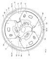
- the recliner 1 includes at least a guide member 10, a ratchet 20, an outer peripheral ring 30, poles 41 to 43, and the like as shown in FIG. That is, the schematic configuration of the recliner 1 is the same as that of the invention described in Patent Document 1.
- the ratchet 20 is fixed to, for example, a back frame (not shown).
- the back frame is a member constituting the skeleton of the seat back.
- the seat back supports the back of the seated person.
- the ratchet 20 is a dish-shaped member having a disk-shaped plate portion 21 and a flange portion 22. As shown in FIG. 2, the plate portion 21 is disposed to face the plate portion 11 of the guide member 10 with a space therebetween.
- the flange portion 22 is an example of a first flange portion in the present disclosure, and is a protrusion that extends from the entire outer edge portion of the plate portion 21 toward the plate portion 11 as shown in FIG.
- the flange portion 22 is integrally formed with the plate portion 21 by subjecting a metal plate to plastic processing such as pressing.
- the guide member 10 is fixed to, for example, a cushion frame (not shown).
- the cushion frame is a member constituting the skeleton of the seat cushion.
- the seat cushion supports the buttocks of the seated person.
- the guide member 10 is a dish-shaped member having a substantially disc-shaped plate portion 11 and a flange portion 12 as shown in FIG.
- the flange portion 12 is an example of a second flange portion in the present disclosure, and is a protrusion that extends from an outer edge portion of the plate portion 11 in a direction orthogonal to the plate portion 11.
- the flange portion 12 is integrally formed with the plate portion 11 by performing plastic working such as press working on the metal plate.
- the ratchet 20 is disposed on the inner peripheral side of the flange portion 12. For this reason, the inner peripheral surface of the flange part 12 and the inner peripheral surface of the flange part 22 can be in sliding contact.
- the guide member 10 and the ratchet 20 are connected by an outer peripheral ring 30.
- the outer peripheral ring 30 restricts the guide member 10 from being separated from the ratchet 20 in a state where the guide member 10 is allowed to rotate relative to the ratchet 20.
- an uneven portion 24 that meshes with the uneven portions 41A to 43A is provided on the inner peripheral surface of the flange portion 22.
- the concave and convex portions 41A to 43A are provided on the poles 41 to 43, respectively.
- Each of the poles 41 to 43 is displaced in contact with the concavo-convex portion 24 by being displaced in the radial direction of the guide member 10.
- the uneven portion 24 corresponds to an example of a first uneven portion in the present disclosure
- each of the uneven portions 41A to 43A corresponds to an example of a second uneven portion in the present disclosure.
- Each of the poles 41 to 43 is stored in a space sandwiched between the guide member 10 and the ratchet 20 (see FIG. 2). Specifically, as shown in FIG. 3, the plurality of poles 41 to 43 are arranged at equal intervals (in the present embodiment, at intervals of 120 degrees) in the circumferential direction of the guide member 10.
- any one of the plurality of poles 41 to 43 (for example, the pole 41) is described as the first pole.
- a pole (for example, pole 42) adjacent to the first pole 41 in the circumferential direction is marked as a second pole.
- the pole 43 is marked as a third pole.
- the hinge cam 44 displaces the plurality of poles 41 to 43.
- the hinge cam 44 is rotated by receiving an operating force from the outside, the concave and convex portions 41A to 43A of the poles 41 to 43 are separated from the concave and convex portion 24.
- the plurality of poles 41 to 43 are displaced to the position where the uneven portions 41A to 43A are fitted into the uneven portion 24 by the elastic force of the spiral spring 45 (see FIG. 4), and then the elastic force causes the Held in position.
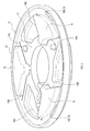
- a plurality of protrusions 13 to 15 are provided on the inner peripheral side of the flange portion 12 in the plate portion 11.
- the plurality of protrusions 13 to 15 are substantially fan-shaped portions protruding toward the plate portion 21 (ratchet 20).
- Guide walls 13 ⁇ / b> A and 13 ⁇ / b> B are provided on the side surface of the protrusion 13.
- Guide walls 14 ⁇ / b> A and 14 ⁇ / b> B are provided on the side surfaces of the protrusion 14.
- Guide walls 15 ⁇ / b> A and 15 ⁇ / b> B are provided on the side surfaces of the protrusion 15.
- Each guide wall 13A to 15B is constituted by a wall surface extending in a direction parallel to the radial direction, as shown in FIG.
- One of the poles 41 to 43 is disposed between two guide walls facing each other among the plurality of guide walls 13A to 15B.
- first pole 41 is located between the guide wall 13A and the guide wall 14B.
- a third pole 43 is located between the guide wall 14A and the guide wall 15B.
- a second pole 42 is located between the guide wall 15A and the guide wall 13B.
- the guide wall 13A and the guide wall 14B guide the displacement of the first pole 41 by slidingly contacting the first pole 41, and restrict the displacement of the first pole 41 in the circumferential direction.
- the guide wall 14A and the guide wall 15B guide the displacement of the third pole 43 by slidingly contacting the third pole 43, and restrict the displacement of the third pole 43 in the circumferential direction.
- the guide wall 15A and the guide wall 13B guide the displacement of the second pole 42 by slidingly contacting the second pole 42, and restrict the displacement of the second pole 42 in the circumferential direction.
- Ratchet seating portions 16A to 16C are provided between two guide walls adjacent in the circumferential direction. Specifically, a ratchet seat 16A is provided between the guide wall 13A and the guide wall 13B.
- a ratchet seat 16B is provided between the guide wall 14A and the guide wall 14B.
- a ratchet seat 16C is provided between the guide wall 15A and the guide wall 15B.
- the ratchet seating portion 16 in the following description means the ratchet seating portions 16A to 16C.
- Each ratchet seating part 16 protrudes toward the flange part 22 of the ratchet 20 as shown in FIG. 6, and can make sliding contact with the tip 22A of the flange part 22.
- Each ratchet seating portion 16 according to the present embodiment is integrally formed of a metal plate material together with the plate portion 11 and the flange portion 12 by plastic working such as press working.
- a guide wall 13A that is in sliding contact with the first pole 41 is defined as a first guide wall, and a guide wall that is adjacent to the first guide wall 13A and that is in sliding contact with the second pole 42.
- the wall 13B is the second guide wall, as shown in FIG. 3, the ratchet seating portion 16A is provided between the first guide wall 13A and the second guide wall 13B in the circumferential direction.
- the ratchet seating portion 16A is provided between the guide walls 13A and 13B of the protrusion 13 in the circumferential direction, and the circumferential length of the ratchet seating portion 16A is shorter than the length of the arc portion 13C.
- the ratchet seating portion 16B is provided between the guide walls 14A and 14B of the protrusion 14 in the circumferential direction, and the circumferential length of the ratchet seating portion 16B is shorter than the length of the arc portion 14C. .
- the ratchet seating portion 16C is provided between the guide walls 15A and 15B of the protrusion 15 in the circumferential direction, and the circumferential length of the ratchet seating portion 16C is shorter than the length of the arc portion 15C. .
- Each ratchet seating portion 16 protrudes toward the flange portion 22 and can make sliding contact with the tip 22A of the flange portion 22.
- the ratchet seating portion 16 is provided on the inner peripheral side of the flange portion 12 of the guide member 10 and between two guide walls adjacent in the circumferential direction of the guide walls 13A to 15B.
- the ratchet 20 is positioned at a position away from the poles 41 to 43 to the extent that they do not interfere with the poles 41 to 43. Accordingly, the height of the plurality of guide walls 13A to 15B can be increased. As a result, the recliner 1 can satisfy the first requirement and the second requirement.
- the recliner 1 since the ratchet seating portion 16 is provided, it is not necessary to configure any one of the punch and the die with two dies. Therefore, in the recliner 1, since the concave portion due to press matching does not occur in principle, the width dimension of the flange portion 12 related to the recliner 1 is smaller than the conventional one.
- Each ratchet seating portion 16 is provided between two guide walls adjacent in the circumferential direction among the plurality of guide walls 13A to 15B, so that the ratchet seating portion 16 is provided over the entire circumference.
- the contact area with the flange portion 22 is reduced. As a result, the sliding resistance between the ratchet (20) and the guide member 10 is reduced.
- the ratchet seating portion 16A is provided between the first guide wall 13A and the second guide wall 13B in the circumferential direction. This reliably reduces the sliding resistance between the ratchet 20 and the guide member 10.
- the guide member 10 is fixed to the cushion frame and the ratchet 20 is fixed to the back frame.
- the present disclosure is not limited to this.
- the guide member 10 may be fixed to the back frame, and the ratchet 20 may be fixed to the cushion frame.
- three poles 41 to 43 are provided.
- the present disclosure is not limited to this. That is, at least one pole according to the present disclosure may be provided, for example.
- the present disclosure is not limited to this. That is, in the present disclosure, for example, if there is one pole, two guide walls are sufficient.
- the ratchet seating portions 16A to 16C according to the above-described embodiment are configured by arc-shaped protrusions extending in the circumferential direction.
- the present disclosure is not limited to this. That is, the ratchet seating part according to the present disclosure may be configured by, for example, a cylindrical protrusion.
- Each of the ratchet seating portions 16A to 16C according to the above-described embodiment is provided at a portion facing the arc portions 13C to 15C of the protrusions 13 to 15.
- the present disclosure is not limited to this. That is, in the present disclosure, for example, the ratchet seating portions 16A to 16C may be disposed between the adjacent protrusions 13 to 15, respectively.
- the protrusions 13 to 15 are configured in a fan shape.
- the present disclosure is not limited to this.
- the protrusions 13 to 15 may be provided and only the guide walls 13A to 15B may be provided.
- the recliner according to the present disclosure is applied to the vehicle seat.
- the application of the present disclosure is not limited to this.
- the present disclosure can also be applied to seats used for vehicles such as railway vehicles, ships, and aircraft, and stationary seats used for theaters, homes, and the like.
- the present disclosure only needs to be consistent with the gist of the present disclosure described in the above embodiment, and is not limited to the above embodiment. Accordingly, a configuration in which at least two embodiments among the plurality of embodiments described above are combined, or a configuration in which any of the configuration requirements of the present disclosure shown in the above embodiments is abolished may be employed.
Landscapes
- Engineering & Computer Science (AREA)
- Aviation & Aerospace Engineering (AREA)
- Transportation (AREA)
- Mechanical Engineering (AREA)
- Chairs For Special Purposes, Such As Reclining Chairs (AREA)
- Seats For Vehicles (AREA)
Abstract
本開示の1つの局面におけるリクライナは、皿状のラチェットと、少なくとも1つのポールと、皿状のガイド部材と、ラチェット着座部とを備える。ラチェット着座部は、ガイド部材のうち、ガイド部材における第2フランジ部より内周側、かつ、ガイド部材において円周方向に隣り合う2つのガイド壁の間に設けられる。ラチェット着座部は、ラチェットにおける第1フランジ部に向けて突出して当該第1フランジ部の先端に滑り接触可能である。
Description
本国際出願は、2018年5月23日に日本国特許庁に出願された日本国特許出願第2018-099023号に基づく優先権を主張するものであり、日本国特許出願第2018-099023号の全内容を本国際出願に参照により援用する。
本開示は、シートバックをシートクッションに対して回転可能に連結するためのリクライナに関する。
リクライナは、例えば、下記特許文献1に記載されているように、クッションフレームに対して固定される皿状のガイド部材、及びバックフレームに対して固定される皿状のラチェット等を少なくとも備え、バックフレームをクッションフレームに対して回転可能に連結する。
ラチェットの外周に設けられた突条のフランジ部には、ポールに設けられた凹凸部に噛み合う凹凸部が設けられている。ポールは、フランジ部に対して離接変位可能である。当該ポールは、ガイド部材とラチェットとに挟まれた空間内に収納されている。
ガイド部材は、ガイド壁を有する。ガイド壁は、ポールがガイド部材の径方向に変位することを案内し、かつ、当該ポールが円周方向に変位することを規制する。ガイド部材とラチェットとは、外周リングにより連結されている。
ポールは、ラチェットとガイド部材とにより挟まれて構成された空間に収納された板状の部材である。ガイド壁は、ポールの端面に滑り接触することにより、当該ポールが円周方向に変位することを規制しながら、ポールの径方向の変位を案内する。
ガイド壁の高さ寸法は、例えば、ポールの板厚寸法の1/2以上であること(以下、第1要件という。)が望ましい。ラチェットは、ポールが収納される空間を構成するので、当該ラチェットは、ポールと干渉しない程度に当該ポールから離間していること(以下、第2要件という。)が望ましい。
本開示の1つの局面は、上記の第1要件及び第2要件を満たすことが可能なリクライナを提供できることが望ましい。
本開示の1つの局面におけるリクライナは、シートバックをシートクッションに対して回転可能に連結するように構成されている。
リクライナは、皿状のラチェットと、少なくとも1つのポールと、皿状のガイド部材と、ラチェット着座部とを備える。ラチェットは、外周部に第1フランジ部を有するとともに、当該第1フランジ部の内周面に第1の凹凸部が設けられている。少なくとも1つのポールは、第1の凹凸部と噛み合い可能な第2の凹凸部を有し、第1の凹凸部と噛み合う位置と当該噛み合う位置から離間した位置との間で変位可能に構成されている。
ガイド部材は、複数のガイド壁と、第2フランジ部とを有する。複数のガイド壁は、少なくとも1つのポールに滑り接触することにより当該少なくとも1つのポールの変位を案内するとともに、当該少なくとも1つのポールが円周方向に変位することを規制するように構成されている。第2フランジ部は、ガイド部材における外周部においてラチェット側に突出している。ラチェット着座部は、第1フランジ部に向けて突出して当該第1フランジ部の先端に滑り接触可能に構成されている。ラチェット着座部は、ガイド部材のうち第2フランジ部より内周側、かつ、複数のガイド壁のうち円周方向において隣り合う2つのガイド壁間に設けられている。
ガイド部材は、複数のガイド壁と、第2フランジ部とを有する。複数のガイド壁は、少なくとも1つのポールに滑り接触することにより当該少なくとも1つのポールの変位を案内するとともに、当該少なくとも1つのポールが円周方向に変位することを規制するように構成されている。第2フランジ部は、ガイド部材における外周部においてラチェット側に突出している。ラチェット着座部は、第1フランジ部に向けて突出して当該第1フランジ部の先端に滑り接触可能に構成されている。ラチェット着座部は、ガイド部材のうち第2フランジ部より内周側、かつ、複数のガイド壁のうち円周方向において隣り合う2つのガイド壁間に設けられている。
このようなリクライナでは、ラチェット着座部が設けられているので、ラチェットは、少なくとも1つのポールと干渉しない程度に当該少なくとも1つのポールから離間した部位に位置する。
ラチェットが少なくとも1つのポールから離間した部位に位置するので、2つのガイド壁の高さを大きくでき得る。したがって、当該リクライナは、上記の第1要件及び第2要件を満たすことが可能となり得る。
さらに、ラチェット着座部は、円周方向において隣り合う2つのガイド壁間に設けられているので、全周に亘ってラチェット着座部が設けられた構成に比べて、第1フランジ部との接触面積が小さくなる。延いては、ラチェットとガイド部材との摺動抵抗が小さくなる。
少なくとも1つのポールは、複数のポールを備えていてもよい。複数のポールは、円周方向において等間隔に配置されていてもよい。複数のポールは、第1ポールと、円周方向において当該第1ポールと隣り合う第2ポールとを備えていてもよい。複数のガイド壁は、第1ポールと滑り接触するように構成された第1ガイド壁と、当該第1ガイド壁と隣り合っていて、且つ第2ポールと滑り接触するように構成された第2ガイド壁とを備えていてもよい。ラチェット着座部は、円周方向において第1ガイド壁と第2ガイド壁との間に設けられていてもよい。
このようなリクライナでは、ラチェットとガイド部材との摺動抵抗がより小さくなり得る。
1…リクライナ 10…ガイド部材 11…プレート部
12…フランジ部 13~15…突起部
13A~15B…ガイド壁 13B…ガイド壁
16A~16C…ラチェット着座部 20…ラチェット
21…プレート部 22…フランジ部 30…外周リング
41~43…ポール
12…フランジ部 13~15…突起部
13A~15B…ガイド壁 13B…ガイド壁
16A~16C…ラチェット着座部 20…ラチェット
21…プレート部 22…フランジ部 30…外周リング
41~43…ポール
以下の「実施形態」は、本開示の技術的範囲に属する実施形態の一例を示すものである。つまり、請求の範囲に記載された事項等は、下記の実施形態に示された具体的構成や構造等に限定されるものではない。
少なくとも符号が付されて説明された部材又は部位は、「1つの」等の断りがされた場合を除き、少なくとも1つ設けられている。つまり、「1つの」等の断りがない場合には、当該部材は2以上設けられていてもよい。
本実施形態は、車両等の乗物に搭載されるシート(以下、乗物用シートという。)に本開示に係るリクライナが適用された例である。各図に付された方向を示す矢印等は、各図相互の関係を理解し易くするために記載されたものである。
したがって、本開示は、各図に付された方向に限定されるものではない。各図に示された方向は、本実施形態に係る乗物用シートが車両に組み付けられた状態における方向である。
(第1実施形態)
1.リクライナの概要
リクライナ1は、例えば、図1に示されるように、ガイド部材10、ラチェット20、外周リング30及びポール41~43等を少なくとも備える。つまり、リクライナ1の概略構成は、上記特許文献1に記載の発明と同じである。
1.リクライナの概要
リクライナ1は、例えば、図1に示されるように、ガイド部材10、ラチェット20、外周リング30及びポール41~43等を少なくとも備える。つまり、リクライナ1の概略構成は、上記特許文献1に記載の発明と同じである。
ラチェット20は、例えばバックフレーム(図示せず。)に対して固定される。バックフレームはシートバックの骨格を構成する部材である。シートバックは、着席者の背部を支持する。
ラチェット20は、円盤状のプレート部21及びフランジ部22を有する皿状の部材である。プレート部21は、図2に示されるように、ガイド部材10のプレート部11と空間を隔てて対向配置される。
フランジ部22は、本開示における第1フランジ部の一例であって、図1に示されるように、プレート部21の外縁部全周からプレート部11側に延出した突条である。フランジ部22は、金属板にプレス加工等の塑性加工が施されてプレート部21と共に一体成形されている。
ガイド部材10は、例えばクッションフレーム(図示せず。)に対して固定される。クッションフレームはシートクッションの骨格を構成する部材である。シートクッションは、着席者の臀部を支持する。
ガイド部材10は、図2に示されるように、略円盤状のプレート部11及びフランジ部12を有する皿状の部材である。フランジ部12は、本開示における第2フランジ部の一例であって、プレート部11の外縁部から当該プレート部11と直交する方向に延出した突条である。
フランジ部12は、金属板にプレス加工等の塑性加工が施されてプレート部11と共に一体成形されている。ラチェット20は、フランジ部12の内周側に配置されている。このため、フランジ部12の内周面とフランジ部22の内周面とは滑り接触可能である。
ガイド部材10とラチェット20とは、外周リング30により連結されている。当該外周リング30は、ガイド部材10がラチェット20に対して相対的に回転することを許容した状態で、当該ガイド部材10がラチェット20から離間することを規制する。
フランジ部22の内周面には、図1に示されるように、凹凸部41A~43Aに噛み合う凹凸部24が設けられている。凹凸部41A~43Aそれぞれは、ポール41~43それぞれに設けられている。各ポール41~43は、ガイド部材10の径方向に変位することより、凹凸部24に対して離接変位する。凹凸部24は、本開示における第1の凹凸部の一例に相当し、凹凸部41A~43Aの各々は、本開示における第2の凹凸部の一例に相当する。
各ポール41~43は、ガイド部材10とラチェット20とに挟まれた空間内に収納されている(図2参照)。具体的には、図3に示されるように、複数のポール41~43は、ガイド部材10の円周方向において等間隔(本実施形態では、120度間隔)で配置されている。
以下の説明では、複数のポール41~43のうちいずれかのポール(例えば、ポール41)が第1ポールと記されている。円周方向において当該第1ポール41と隣り合うポール(例えば、ポール42)が第2ポールと記されている。なお、ポール43は、第3ポールと記されている。
ヒンジカム44は、複数のポール41~43を変位させる。当該ヒンジカム44は、外部から操作力を受けて回転すると、各ポール41~43の凹凸部41A~43Aを凹凸部24から離間させる。
当該操作力が消失すると、複数のポール41~43は、スパイラルばね45(図4参照)の弾性力によって凹凸部41A~43Aが凹凸部24に嵌り込む位置まで変位した後、当該弾性力によって当該位置に保持される。
2.ガイド部材の構成
図5に示されるように、プレート部11のうちフランジ部12より内周側には、複数の突起部13~15が設けられている。複数の突起部13~15は、プレート部21(ラチェット20)側に突出した略扇状の部位である。
図5に示されるように、プレート部11のうちフランジ部12より内周側には、複数の突起部13~15が設けられている。複数の突起部13~15は、プレート部21(ラチェット20)側に突出した略扇状の部位である。
突起部13の側面にはガイド壁13A、13Bが設けられている。突起部14の側面にはガイド壁14A、14Bが設けられている。突起部15の側面にはガイド壁15A、15Bが設けられている。
各ガイド壁13A~15Bは、図3に示されるように、径方向と平行な方向に延びる壁面により構成されている。そして、複数のガイド壁13A~15Bのうち互いに対向する2つのガイド壁間には、ポール41~43のいずれかが配置されている。
具体的には、ガイド壁13Aとガイド壁14Bとの間には、第1ポール41が位置されている。ガイド壁14Aとガイド壁15Bとの間には、第3ポール43が位置されている。ガイド壁15Aとガイド壁13Bとの間には、第2ポール42が位置されている。
つまり、ガイド壁13A及びガイド壁14Bは、第1ポール41に滑り接触することにより第1ポール41の変位を案内するとともに、当該第1ポール41が円周方向に変位することを規制する。
ガイド壁14A及びガイド壁15Bは、第3ポール43に滑り接触することにより第3ポール43の変位を案内するとともに、当該第3ポール43が円周方向に変位することを規制する。
ガイド壁15A及びガイド壁13Bは、第2ポール42に滑り接触することにより第2ポール42の変位を案内するとともに、当該第2ポール42が円周方向に変位することを規制する。
円周方向において隣り合う2つのガイド壁間それぞれには、ラチェット着座部16A~16Cが設けられている。具体的には、ガイド壁13Aとガイド壁13Bとの間には、ラチェット着座部16Aが設けられている。
ガイド壁14Aとガイド壁14Bとの間には、ラチェット着座部16Bが設けられている。ガイド壁15Aとガイド壁15Bとの間には、ラチェット着座部16Cが設けられている。以下の説明におけるラチェット着座部16は、ラチェット着座部16A~16Cを意味している。
各ラチェット着座部16は、図6に示されるように、ラチェット20のフランジ部22に向けて突出して当該フランジ部22の先端22Aに滑り接触可能である。本実施形態に係る各ラチェット着座部16は、プレス加工等の塑性加工により、プレート部11及びフランジ部12と共に金属製の板材により一体成形されている。
複数のガイド壁13A~15Bのうち第1ポール41と滑り接触するガイド壁13Aを第1ガイド壁とし、当該第1ガイド壁13Aと隣り合うガイド壁であって第2ポール42と滑り接触するガイド壁13Bを第2ガイド壁としたとき、図3に示されるように、ラチェット着座部16Aは、円周方向において第1ガイド壁13Aと前記第2ガイド壁13Bとの間に設けられている。
つまり、ラチェット着座部16Aは、円周方向において、突起部13のガイド壁13A、13B間に設けられ、かつ、当該ラチェット着座部16Aの円周方向長さは、円弧部13Cの長さより短い。
同様に、ラチェット着座部16Bは、円周方向において、突起部14のガイド壁14A、14B間に設けられ、かつ、当該ラチェット着座部16Bの円周方向長さは、円弧部14Cの長さより短い。
同様に、ラチェット着座部16Cは、円周方向において、突起部15のガイド壁15A、15B間に設けられ、かつ、当該ラチェット着座部16Cの円周方向長さは、円弧部15Cの長さより短い。
3.本実施形態に係るリクライナの特徴
各ラチェット着座部16は、フランジ部22に向けて突出して当該フランジ部22の先端22Aに滑り接触可能である。当該ラチェット着座部16は、ガイド部材10のうちフランジ部12より内周側、かつ、ガイド壁13A~15Bのうち円周方向において隣り合う2つのガイド壁間に設けられている。
各ラチェット着座部16は、フランジ部22に向けて突出して当該フランジ部22の先端22Aに滑り接触可能である。当該ラチェット着座部16は、ガイド部材10のうちフランジ部12より内周側、かつ、ガイド壁13A~15Bのうち円周方向において隣り合う2つのガイド壁間に設けられている。
これにより、ラチェット20は、ポール41~43と干渉しない程度に当該ポール41~43から離間した部位に位置する。したがって、複数のガイド壁13A~15Bの高さが大きくなり得る。延いては、リクライナ1は、上記の第1要件及び第2要件を満たすことが可能となる。
なお、複数のガイド壁13A~15Bの高さを大きくする手法として、ガイド部材10をプレス成形するためのパンチ及びダイのうち、いずれかを2つの金型にて構成する手法がある。
しかし、上記手法では、2つの金型のプレスマッチング部分、つまりフランジ部12の内周面に、製造上、凹部が発生してしまう。当該凹部が発生すると、当該凹部が製造上の障害となるため、上記手法では、フランジ部12の幅寸法を従来に比べて小さくしたリクライナを製造できない。
これに対して、本実施形態に係るリクライナ1では、ラチェット着座部16が設けられているので、パンチ及びダイのうち、いずれかを2つの金型にて構成する必要がない。したがって、当該リクライナ1では、プレスマッチングに起因する凹部が原理的に発生しないので、当該リクライナ1に係るフランジ部12の幅寸法は、従来に比べて小さくなる。
各ラチェット着座部16は、複数のガイド壁13A~15Bのうち円周方向において隣り合う2つのガイド壁間に設けられているので、全周に亘ってラチェット着座部が設けられた構成に比べて、フランジ部22との接触面積が小さくなる。延いては、ラチェット(20)とガイド部材10との摺動抵抗が小さくなる。
例えば、ラチェット着座部16Aは、円周方向において第1ガイド壁13Aと第2ガイド壁13Bとの間に設けられている。これにより、ラチェット20とガイド部材10との摺動抵抗が確実に小さくなる。
(その他の実施形態)
上述の実施形態では、ガイド部材10がクッションフレームに対して固定され、かつ、ラチェット20がバックフレームに対して固定されるリクライナであった。しかし、本開示はこれに限定されるものではない。
上述の実施形態では、ガイド部材10がクッションフレームに対して固定され、かつ、ラチェット20がバックフレームに対して固定されるリクライナであった。しかし、本開示はこれに限定されるものではない。
すなわち、本開示に係るリクライナは、例えば、ガイド部材10がバックフレームに対して固定され、かつ、ラチェット20がクッションフレームに対して固定されてもよい。
上述の実施形態では、3のポール41~43が設けられていた。しかし、本開示はこれに限定されるものではない。すなわち、本開示に係るポールは、例えば、少なくとも1つ設けられていてればよい。
上述の実施形態では、3のポール41~43が設けられていたため、6つのガイド壁が設けられていた。しかし、本開示はこれに限定されるものではない。すなわち、本開示は、例えば、ポールが1つであるならば、ガイド壁は2つで十分である。
上述の実施形態に係るラチェット着座部16A~16Cは、円周方向に延びる円弧状の突条にて構成されていた。しかし、本開示はこれに限定されるものではない。すなわち、本開示に係るラチェット着座部は、例えば、円柱状の突起部により構成されていてもよい。
上述の実施形態に係るラチェット着座部16A~16Cそれぞれは、突起部13~15の円弧部13C~15Cに面した部位に設けられていた。しかし、本開示はこれに限定されるものではない。すなわち、本開示では、例えば、ラチェット着座部16A~16Cそれぞれが隣り合う突起部13~15間に配置されていてもよい。
上述の実施形態に係る突起部13~15は、扇状に構成されていた。しかし、本開示はこれに限定されるものではない。すなわち、本開示では、例えば、突起部13~15がなく、ガイド壁13A~15Bのみが設けられた突条であってもよい。
上述の実施形態では、車両用シートに本開示に係るリクライナを適用した。しかし、本開示の適用はこれに限定されるものではない。本開示は、鉄道車両、船舶及び航空機等の乗物に用いられるシート、並びに劇場や家庭用等に用いられる据え置き型シートにも適用できる。
さらに、本開示は、上述の実施形態に記載された本開示の趣旨に合致するものであればよく、上述の実施形態に限定されるものではない。したがって、上述した複数の実施形態のうち少なくとも2つの実施形態が組み合わせられた構成、又は上述の実施形態に示された本開示の構成要件のうちいずれかが廃止された構成でもよい。
Claims (2)
- シートバックをシートクッションに対して回転可能に連結するためのリクライナにおいて、
外周部に第1フランジ部を有するとともに、当該第1フランジ部の内周面に第1の凹凸部が設けられた皿状のラチェットと、
前記第1の凹凸部と噛み合い可能な第2の凹凸部を有する少なくとも1つのポールであって、前記第1の凹凸部と噛み合う位置と当該噛み合う位置から離間した位置との間で変位可能に構成された少なくとも1つのポールと、
前記少なくとも1つのポールに滑り接触することにより当該少なくとも1つのポールの変位を案内するとともに当該少なくとも1つのポールが円周方向に変位することを規制するように構成された複数のガイド壁、及び外周部に前記ラチェット側に突出した第2フランジ部を有する皿状のガイド部材と、
前記第1フランジ部に向けて突出して当該第1フランジ部の先端に滑り接触可能に構成されたラチェット着座部であって、前記ガイド部材のうち前記第2フランジ部より内周側、かつ、前記複数のガイド壁のうち円周方向において隣り合う2つのガイド壁間に設けられたラチェット着座部と
を備えるリクライナ。
- 請求項1に記載のリクライナであって、
前記少なくとも1つのポールは複数のポールを備え、
前記複数のポールは、円周方向において等間隔に配置されており、
前記複数のポールは、
第1ポールと、
円周方向において前記第1ポールと隣り合う第2ポールと
を備え、
前記複数のガイド壁は、
前記第1ポールと滑り接触するように構成された第1ガイド壁と、
前記第1ガイド壁と隣り合っていて、且つ前記第2ポールと滑り接触するように構成された第2ガイド壁と、
を備え、
前記ラチェット着座部は、円周方向において前記第1ガイド壁と前記第2ガイド壁との間に設けられているリクライナ。
Priority Applications (2)
| Application Number | Priority Date | Filing Date | Title |
|---|---|---|---|
| US17/056,294 US11059397B1 (en) | 2018-05-23 | 2019-05-14 | Recliner |
| CN201980034281.3A CN112154081B (zh) | 2018-05-23 | 2019-05-14 | 倾斜角度调节器 |
Applications Claiming Priority (2)
| Application Number | Priority Date | Filing Date | Title |
|---|---|---|---|
| JP2018099023A JP6950624B2 (ja) | 2018-05-23 | 2018-05-23 | リクライナ |
| JP2018-099023 | 2018-05-23 |
Publications (1)
| Publication Number | Publication Date |
|---|---|
| WO2019225403A1 true WO2019225403A1 (ja) | 2019-11-28 |
Family
ID=68617364
Family Applications (1)
| Application Number | Title | Priority Date | Filing Date |
|---|---|---|---|
| PCT/JP2019/019113 Ceased WO2019225403A1 (ja) | 2018-05-23 | 2019-05-14 | リクライナ |
Country Status (4)
| Country | Link |
|---|---|
| US (1) | US11059397B1 (ja) |
| JP (1) | JP6950624B2 (ja) |
| CN (1) | CN112154081B (ja) |
| WO (1) | WO2019225403A1 (ja) |
Citations (1)
| Publication number | Priority date | Publication date | Assignee | Title |
|---|---|---|---|---|
| KR20110135535A (ko) * | 2010-06-11 | 2011-12-19 | 주식회사다스 | 차량용 시트의 리클라이너 |
Family Cites Families (14)
| Publication number | Priority date | Publication date | Assignee | Title |
|---|---|---|---|---|
| US6520583B1 (en) * | 2000-08-24 | 2003-02-18 | Fisher Dynamics Corporation | Compact disc recliner |
| JP2010213839A (ja) | 2009-03-16 | 2010-09-30 | Toyota Boshoku Corp | 車両用シートの連結装置 |
| FR2949719B1 (fr) * | 2009-09-09 | 2011-09-23 | Faurecia Sieges Automobile | Mecanisme de reglage d'inclinaison de siege de vehicule automobile, siege de vehicule et procede de fabrication. |
| JP5592743B2 (ja) * | 2009-10-29 | 2014-09-17 | 富士機工株式会社 | 車両用シートリクライニング装置 |
| JP5592204B2 (ja) * | 2010-09-01 | 2014-09-17 | シロキ工業株式会社 | リクライニング装置 |
| DE102010042057A1 (de) * | 2010-10-06 | 2012-04-12 | Lear Corp. | Synchronisiereinrichtung für manuelle Lehnenverstellvorrichtung |
| FR2972972B1 (fr) * | 2011-03-22 | 2013-04-26 | Faurecia Sieges Automobile | Systeme d'articulation et siege de vehicule comportant un tel systeme d'articulation |
| JP5768560B2 (ja) * | 2011-07-26 | 2015-08-26 | トヨタ紡織株式会社 | 車両用シートの回転軸装置 |
| JP6064826B2 (ja) * | 2013-08-01 | 2017-01-25 | トヨタ紡織株式会社 | リクライナ |
| JP2015067147A (ja) * | 2013-09-30 | 2015-04-13 | トヨタ紡織株式会社 | 乗物用シート |
| US20150321585A1 (en) * | 2014-05-12 | 2015-11-12 | Lear Corporation | Recliner Mechanism |
| JP2016159687A (ja) * | 2015-02-27 | 2016-09-05 | シロキ工業株式会社 | シートリクライニング装置 |
| JP6485218B2 (ja) * | 2015-05-26 | 2019-03-20 | トヨタ紡織株式会社 | リクライナ |
| CN106240408B (zh) * | 2016-08-31 | 2019-07-26 | 宁波志海汽车部件科技发展有限公司 | 一种汽车座椅用小型调角器 |
-
2018
- 2018-05-23 JP JP2018099023A patent/JP6950624B2/ja active Active
-
2019
- 2019-05-14 US US17/056,294 patent/US11059397B1/en active Active
- 2019-05-14 WO PCT/JP2019/019113 patent/WO2019225403A1/ja not_active Ceased
- 2019-05-14 CN CN201980034281.3A patent/CN112154081B/zh active Active
Patent Citations (1)
| Publication number | Priority date | Publication date | Assignee | Title |
|---|---|---|---|---|
| KR20110135535A (ko) * | 2010-06-11 | 2011-12-19 | 주식회사다스 | 차량용 시트의 리클라이너 |
Also Published As
| Publication number | Publication date |
|---|---|
| JP6950624B2 (ja) | 2021-10-13 |
| JP2019201893A (ja) | 2019-11-28 |
| CN112154081A (zh) | 2020-12-29 |
| CN112154081B (zh) | 2023-01-31 |
| US20210206298A1 (en) | 2021-07-08 |
| US11059397B1 (en) | 2021-07-13 |
Similar Documents
| Publication | Publication Date | Title |
|---|---|---|
| US11426781B2 (en) | Forming method of disk-shaped member | |
| US9227533B2 (en) | Recliner | |
| US20150035339A1 (en) | Recliner | |
| KR20150130306A (ko) | 테이퍼형 핀 캠 표면을 갖는 디스크 리클라이너 | |
| CN109094433B (zh) | 用于车辆座椅的倾斜器 | |
| JP2018023583A (ja) | シートリクライニング装置 | |
| JP2017153851A (ja) | シートリクライニング装置 | |
| US20160009201A1 (en) | Recliner of vehicle seat | |
| WO2014199846A1 (ja) | リクライニング装置 | |
| JP2015504819A (ja) | ワンピース型背もたれ構造体の製造方法 | |
| JP2018035871A (ja) | クラッチユニット | |
| JP2014058246A (ja) | シートリクライニング装置 | |
| WO2019225227A1 (ja) | 回転連結体、及びその製造方法 | |
| WO2019225403A1 (ja) | リクライナ | |
| WO2013122215A1 (ja) | 弾性部材 | |
| WO2015012287A1 (ja) | リクライニング機構 | |
| US11872915B2 (en) | Vehicle seat reclining device | |
| JP7180468B2 (ja) | 乗物用シートリクライニング装置 | |
| KR20190036905A (ko) | 차량용 시트의 리클라이너 | |
| JP2016533297A (ja) | 車両シート、特に自動車シート | |
| KR101586948B1 (ko) | 차량용 시트의 리클라이너 | |
| JP2015030300A (ja) | ドアミラー取付構造 | |
| JP6154238B2 (ja) | リクライニング機構 | |
| KR101678416B1 (ko) | 자동차 시트의 리클라이너 장치 | |
| JP2016077835A (ja) | 回転動作制御機構及びシート |
Legal Events
| Date | Code | Title | Description |
|---|---|---|---|
| 121 | Ep: the epo has been informed by wipo that ep was designated in this application |
Ref document number: 19807591 Country of ref document: EP Kind code of ref document: A1 |
|
| NENP | Non-entry into the national phase |
Ref country code: DE |
|
| 122 | Ep: pct application non-entry in european phase |
Ref document number: 19807591 Country of ref document: EP Kind code of ref document: A1 |