WO2019220569A1 - 吸収性物品用の吸収体 - Google Patents
吸収性物品用の吸収体 Download PDFInfo
- Publication number
- WO2019220569A1 WO2019220569A1 PCT/JP2018/018932 JP2018018932W WO2019220569A1 WO 2019220569 A1 WO2019220569 A1 WO 2019220569A1 JP 2018018932 W JP2018018932 W JP 2018018932W WO 2019220569 A1 WO2019220569 A1 WO 2019220569A1
- Authority
- WO
- WIPO (PCT)
- Prior art keywords
- absorbent
- opening
- fibers
- long fibers
- absorbent core
- Prior art date
- Legal status (The legal status is an assumption and is not a legal conclusion. Google has not performed a legal analysis and makes no representation as to the accuracy of the status listed.)
- Ceased
Links
Images


Classifications
-
- A—HUMAN NECESSITIES
- A61—MEDICAL OR VETERINARY SCIENCE; HYGIENE
- A61F—FILTERS IMPLANTABLE INTO BLOOD VESSELS; PROSTHESES; DEVICES PROVIDING PATENCY TO, OR PREVENTING COLLAPSING OF, TUBULAR STRUCTURES OF THE BODY, e.g. STENTS; ORTHOPAEDIC, NURSING OR CONTRACEPTIVE DEVICES; FOMENTATION; TREATMENT OR PROTECTION OF EYES OR EARS; BANDAGES, DRESSINGS OR ABSORBENT PADS; FIRST-AID KITS
- A61F13/00—Bandages or dressings; Absorbent pads
- A61F13/15—Absorbent pads, e.g. sanitary towels, swabs or tampons for external or internal application to the body; Supporting or fastening means therefor; Tampon applicators
- A61F13/53—Absorbent pads, e.g. sanitary towels, swabs or tampons for external or internal application to the body; Supporting or fastening means therefor; Tampon applicators characterised by the absorbing medium
- A61F13/531—Absorbent pads, e.g. sanitary towels, swabs or tampons for external or internal application to the body; Supporting or fastening means therefor; Tampon applicators characterised by the absorbing medium having a homogeneous composition through the thickness of the pad
- A61F13/532—Absorbent pads, e.g. sanitary towels, swabs or tampons for external or internal application to the body; Supporting or fastening means therefor; Tampon applicators characterised by the absorbing medium having a homogeneous composition through the thickness of the pad inhomogeneous in the plane of the pad
-
- A—HUMAN NECESSITIES
- A61—MEDICAL OR VETERINARY SCIENCE; HYGIENE
- A61F—FILTERS IMPLANTABLE INTO BLOOD VESSELS; PROSTHESES; DEVICES PROVIDING PATENCY TO, OR PREVENTING COLLAPSING OF, TUBULAR STRUCTURES OF THE BODY, e.g. STENTS; ORTHOPAEDIC, NURSING OR CONTRACEPTIVE DEVICES; FOMENTATION; TREATMENT OR PROTECTION OF EYES OR EARS; BANDAGES, DRESSINGS OR ABSORBENT PADS; FIRST-AID KITS
- A61F13/00—Bandages or dressings; Absorbent pads
- A61F13/15—Absorbent pads, e.g. sanitary towels, swabs or tampons for external or internal application to the body; Supporting or fastening means therefor; Tampon applicators
- A61F13/53—Absorbent pads, e.g. sanitary towels, swabs or tampons for external or internal application to the body; Supporting or fastening means therefor; Tampon applicators characterised by the absorbing medium
- A61F13/538—Absorbent pads, e.g. sanitary towels, swabs or tampons for external or internal application to the body; Supporting or fastening means therefor; Tampon applicators characterised by the absorbing medium characterised by specific fibre orientation or weave
Definitions
- the present invention relates to an absorbent body for absorbent articles such as sanitary napkins and disposable diapers.
- Patent Document 1 discloses an absorbent core including (cellulosic) absorbent fibers, such as pulp fibers, encapsulated in a liquid-permeable sheet and shaped into a required shape, and superabsorbent polymer particles.
- An absorber comprising
- the absorbent body disclosed in Patent Document 1 is relatively thin and has a plurality of openings that penetrate the absorbent core in the thickness direction. It is excellent in nature and can be deformed and fitted so as to conform to the wearer's body shape in the wearing state.
- the present invention is an improvement of an absorbent body for a conventional absorbent article, in which an opening is not greatly deformed during wearing and is not completely closed, and exhibits desired air permeability and flexibility.
- An object of the present invention is to provide an absorbent body for an absorbent article.
- the first and second inventions of the present application relate to an absorbent body for absorbent articles.
- An absorbent body for an absorbent article according to the first invention of the present application includes an absorbent core having a thickness direction, a first surface and a second surface facing each other in the thickness direction, and the absorbent core A plurality of openings substantially penetrating in the thickness direction, wherein the absorbent core includes a water absorbent fiber and a long fiber longer than the water absorbent fiber, and the long fiber is in the thickness direction. In the present invention, it is located on the inner peripheral surface of the opening and extends from the first surface to the second surface without being cut.
- the absorbent body for absorbent articles according to the second invention of the present application wherein the absorbent body has a thickness direction, an absorbent core, and a plurality of openings substantially penetrating the absorbent core.
- the absorbent core includes water-absorbing fibers, superabsorbent polymer particles, and long fibers longer than the water-absorbing fibers, and the area of the opening is 12 mm 2 or more, and the absorbent core is in a wet state.
- the ventilation resistance value of the region including the opening of the body is 50% or less of the ventilation resistance value of the region not including the opening.
- the first and second inventions of the present application include the following preferred embodiments.
- the long fibers intersect each other directly or indirectly on the inner peripheral surface of the opening.
- the long fibers are uniformly arranged in the entire absorbent core.
- the long fibers are densely arranged in the opening edge of the opening compared to other regions.
- the opening is not disposed on the outer peripheral edge of the absorbent core.
- the area of the first opening end located on the first surface side of the opening is different from the area of the second opening end located on the second surface side.
- the opening is seen through from at least one of the inner surface and the outer surface of the absorbent article. (7) A part of the long fibers straddles the opening.
- the long fibers are thermoplastic resin fibers and have an average fiber length of 6 to 70 mm.
- the long fibers are heat-sealed at portions that intersect each other.
- the area of each of the openings is 12 to 150 mm 2 , and the ratio of the total area of the plurality of openings to the area of the absorbent core is 1 to 50%.
- the absorbent body for absorbent articles according to the present invention even when the absorbent body is sandwiched between the buttocks of the wearer or the SAP particles absorb body fluid and swell in the worn state, the opening is large. It can suppress that it loses shape and is completely blocked.
- FIG. 2A The expanded view of the area
- FIG. 4 (a) after body fluid absorption.
- the following embodiment relates to the absorbent body for the disposable absorbent article shown in FIGS. 1 to 7 and includes not only an indispensable structure of the invention but also a selective and preferable structure.
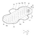
- a sanitary napkin 10 shown as an example of the absorbent article of the first and second inventions of the present application is positioned in the longitudinal direction Y and the lateral direction X, on the skin facing surface and on the opposite side thereof.
- a non-skin-facing surface that includes a liquid-permeable top sheet 11, a liquid-impervious back sheet 12, and an absorber 13 interposed between the two sheets.
- the back sheet 12 extends further outward in the lateral direction than the top sheet 11, and a pair of side sheets 15 are fixed on the front side.
- An end flap 16 located outside the absorbent body 13 in the longitudinal direction Y is formed by a part of the top sheet 11, the back sheet 12, and the side sheet 15, and the back sheet 12 and the side sheet 15 form the end flap 16.
- a pair of side flaps 17 are also formed which are located outside in the lateral direction X and have a pair of wings that protrude outward in the lateral direction X at the central portion.
- the sheets 11, 12, 15 facing each other are bonded to each other via a known bonding means, for example, a hot melt adhesive, and welded to each other via an outer peripheral seal portion 19 extending along the outer periphery of the sanitary napkin. Has been.
- the top sheet 11 is formed of thermoplastic resin fibers such as a spunbond nonwoven fabric, a meltbond nonwoven fabric, a meltblown nonwoven fabric, a SMS nonwoven fabric in which a spunbond nonwoven fabric, a meltblown nonwoven fabric, and a spunbond nonwoven fabric are laminated.
- thermoplastic resin fibers such as a spunbond nonwoven fabric, a meltbond nonwoven fabric, a meltblown nonwoven fabric, a SMS nonwoven fabric in which a spunbond nonwoven fabric, a meltblown nonwoven fabric, and a spunbond nonwoven fabric are laminated.
- a non-woven fabric or a perforated plastic film can be used.
- the back sheet 12 is made of a material commonly used in the art, for example, a liquid-impervious or moisture-permeable liquid-impervious plastic film, a fiber nonwoven fabric formed from various thermoplastic resin fibers, and a plastic film.
- a laminate sheet in which a fiber nonwoven fabric is bonded to the outer surface can be suitably used.
- the absorbent body 13 has an absorbent core 20 shaped into a required shape, and a core wrap sheet 21 that covers the absorbent core 20.
- the core wrap sheet 21 is an option, and the absorbent body 13 may be formed only from the absorbent core 20 as long as the absorbent core 20 has the required shape retention.
- the absorber 13 is higher in rigidity and semi-rigid than the respective sheets, and the first and second end edges 13a and 13b and the first and second end edges 13a and 13b are curved outward in the longitudinal direction Y. And both side edges 13c and 13d extending linearly in the longitudinal direction Y between them.
- a middle-high portion 22 in which the thickness dimension of the absorbent core 20 is made larger than the thickness dimension of other portions is formed at the center portion of the absorbent body 13 on the skin facing surface side.
- the mass of the absorbent core 20 is higher in the central portion of the absorbent body 13 in the longitudinal direction Y and the lateral direction X than in other regions, and the thickness dimension is larger than in other regions. Large mid-high portions can also be formed.
- the middle-high part in the absorbent body 13, the middle-high part can be brought into close contact with the wearer's excretion port, and menstrual blood can be absorbed and retained more effectively.
- the opening part 40 does not need to be sparsely arranged in the middle-high part.
- the absorbent core 20 is formed from a mixture including water absorbent fibers 25, super absorbent polymer particles (SAP (super absorbent polymer) particles) 26 and long fibers 30 longer than the water absorbent fibers 25.
- the water-absorbent fibers 25 include cellulose-based materials commonly used in the technical field, for example, non-wood pulp made from softwood or hardwood, hemp, cotton, etc., and recycled cellulose fibers such as rayon fiber. Semi-rigid fibers such as acetate fibers are preferably used.
- SAP particles 26 those well known in the art can be used.
- particles formed of polyacrylic acid, polyacrylic acid salt, starch acrylonitrile copolymer, polyvinyl alcohol, polyvinyl ether, polyacrylamide, carboxymethyl cellulose, natural polysaccharide, etc. can be used.
- the long fiber 30 is a natural fiber or a synthetic fiber having a fiber length longer than that of the water-absorbing fiber 25.
- a thermoplastic resin fiber is used.
- the thermoplastic resin fiber is a single fiber formed by using a single component such as polyethylene (PE), polypropylene (PP), polyethylene terephthalate (PET), nylon, or a composite fiber composed of a plurality of these components.
- the composite fiber preferably contains at least two kinds of components having different melting points, such as core-sheath fiber, side-by-side fiber, sea-island fiber, flat fiber, Y-shaped fiber, C-shaped fiber, etc. Is used.
- a core-sheath fiber such as PET / PE, PP / PE (core / sheath part), etc., particularly a core-sheath fiber in which the melting point of the sheath part is lower than the melting point of the core part.
- a core-sheath fiber such as PET / PE, PP / PE (core / sheath part), etc.
- a core-sheath fiber in which the melting point of the sheath part is lower than the melting point of the core part are preferably used.
- the mass ratio, the cross-sectional area ratio, and the diameter ratio of the core component and the sheath component in consideration of the required crimp rate, spinnability at the time of manufacture, etc.
- the ratio of the sheath component is 10/90 to 90/10, preferably, 30/70 to 70/30.
- the “melting point” of the thermoplastic resin fiber means a peak top temperature of an endothermic peak when changing from a solid state to a liquid state when measured at a temperature rising rate of 10 ° C./min in a differential running calorimeter.
- a differential calorimetric analyzer for example, a DSC-60 type DSC measuring apparatus manufactured by Shimadzu Corporation can be used.
- the core wrap sheet 21 is used for shape retention of the liquid diffusible and absorbent core 20, and is made of thermoplastic resin fibers and subjected to a hydrophilic treatment in addition to tissue paper. Nonwoven fabrics and the like can be used.
- the core wrap sheet 21 may be a single sheet that covers the entire absorbent core 20, an upper core wrap sheet that covers the skin facing surface side of the absorbent core, and a non-skin facing surface. You may form from the several sheet
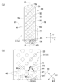
- the absorbent core 20 is formed with a plurality of openings 40 that are spaced apart from each other in the vertical direction Y and the horizontal direction X.
- the absorber 13 (absorbent core 20) has a longitudinal center line P that bisects the dimension in the horizontal direction X and a transverse center line Q that bisects the dimension in the vertical direction Y.
- the openings 40 have a square shape and are arranged in a so-called zigzag pattern arranged at equal intervals in the lateral direction X and the longitudinal direction Y, and extend obliquely with respect to the longitudinal centerline P and the transverse centerline Q.
- a plurality of rows 50 are formed. Specifically, a plurality of columns 50 are formed along a first direction K1 that is inclined with respect to the longitudinal center line P and the transverse center line Q, and each column is perpendicular to the first direction K1.
- the two directions K2 are spaced apart from each other.
- the first direction K1 can intersect with the longitudinal center line P at an appropriate inclination angle, but in the illustrated example, the first direction K1 intersects with an inclination of about 45 degrees.
- the plurality of openings 40 may be arranged at different intervals instead of at equal intervals.
- the absorbent core 20 is excellent in flexibility, and in a state where the absorbent body 13 is sandwiched between the buttocks of the wearer, the absorbent core 20 is bent at a plurality of locations starting from the vicinity of the opening, thereby forming a curved body shape. Can be deformed along.
- the length t1 of one side of the opening 40 is 4 to 15 mm, preferably 6 to 12 mm.
- the opening 40 is easily crushed during wearing, and the air permeability may be reduced.
- the length t1 of one side exceeds 15 mm, the opening 40 becomes relatively large, and there is a risk of giving anxiety about absorbency to the wearer and / or the wear assistant. Actually, body fluids such as menstrual blood and urine are not easily transferred to the absorber 13, and the absorption performance may be reduced.
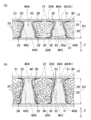
- the absorber 13 includes a first surface (skin facing surface or non-skin facing surface) 20A and a second surface (non-skin facing) that face each other in the thickness direction Z.
- Surface or skin facing surface) 20B In the present embodiment, the first surface 20A is a skin facing surface, and the second surface 20B is a non-skin facing surface.
- the opening 40 includes a first opening end 40A located on the first surface 20A side, a second opening end 40B located on the second surface 20B side, and the first opening end 40A and the second opening in the thickness direction Z, respectively. And an inner peripheral surface 40C positioned between the opening end 40B.
- the some opening part 40 formed in the absorptive core 20 has the structure of a postscript, and the technical effect by it, except for the one part except for the part.
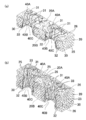
- 4A and 4B are views of the skin facing surface side (first surface 20A side) of the absorbent core 40 as viewed obliquely, but the skin facing surface side or non-skin of the absorber 40 is not shown. It is preferable that at least one of the facing surface (second surface 20B) has the illustrated mode.
- the opening 40 is a through-hole that substantially penetrates the absorbent core 20 in the thickness direction Z, and the thickness D1 of the absorbent core 20 is 0.5 to 15 mm, preferably 3 ⁇ 12 mm. Since the opening 40 is a through hole that substantially penetrates the absorbent core 20, the depth of the opening (the dimension in the thickness direction Z) is substantially equal to the thickness dimension D ⁇ b> 1 of the absorbent core 20. .
- a plurality of long fibers 30 extend from the first surface side 20A to the second surface 20B side without being cut.
- the long fiber 30 includes a first end 31 extending outward from the first opening end 40A of the opening 40 on the first surface 20A side, and a second end of the opening 40 on the second surface 20B side.
- a second end 32 extending outward from the opening end 40B and an intermediate portion extending in the thickness direction Z so as to longitudinally cut the inner peripheral surface 40C of the opening 40 between the first and second ends 31 and 32.
- the absorbent core 20 becomes thick by being absorbed and swollen by the water-absorbing fibers 25 and the SAP particles 26 and by temporarily storing body fluid in the fiber gap.
- the inward pressing force acts on both side edges of the absorbent body 13 and is formed over the entire area of the absorbent core 20.
- the plurality of opened openings 40 may collapse and close.
- the SAP particles 26 that have absorbed and retained the body fluid swell and gel, and the plurality of SAP particles 26 gather together to form a lump.
- the SAP particles 26 are gelled and formed into a lump, the lump-shaped portion tends to enter the opening 40, and the shape of the peripheral edge is broken, making it difficult to maintain the opening shape before excretion.
- the opening area of the opening 40 is reduced by the clamping force between the wearer's buttocks and the swelling of the SAP particles 26, and the absorbent core 20 exhibits desired air permeability and ease of deformation. It may not be possible.
- the plurality of long fibers 30 are not cut on the inner peripheral surface 40C of the opening 40 and extend in the thickness direction Z to the first surface 20A and the second surface 20B.
- the rigidity of the inner peripheral surface 40C of the opening 40 is increased, and the shape can be prevented from collapsing. Therefore, even if the absorbent body 13 is pinched between the wearer's buttocks, the opening 40 does not greatly lose its shape, and even if the SAP particles 26 are agglomerated and try to close the opening 40, the long fibers 30 prevents the SAP particles 26 from entering the opening 40 and the opening 40 is not completely closed.
- the absorbent body 13 when the opening 40 is shaped so that the opening area can be maintained to a certain extent, the absorbent body 13 exhibits desired breathability and ease of deformation, so that it can be steamed and worn on the body. It can suppress that the followability with respect to a motion falls.
- the long fibers 30 cross each other directly or indirectly through the other long fibers 30 on the inner peripheral surface 40C of the opening 40.
- an intermediate portion 33 of two arbitrarily selected long fibers 30 first and second long fibers
- the two long fibers 30 indirectly cross the intermediate portion 33 of one or more other long fibers (third long fibers) 30 different from the two long fibers 30.
- a network structure by the long fibers 30 is formed.
- higher shape retention can be exhibited.
- the fact that the long fibers 30 cross each other includes not only simply overlapping each other in the thickness direction of the absorbent core 20 but also including entanglement of the fibers.
- the entanglement of fibers includes not only the case where the fibers are physically entangled but also the case where an entanglement point is formed in which the thermoplastic resin fibers are thermally welded to each other by heat treatment during production.
- the long fiber 30 of the present embodiment includes any aspect of mere intersection, physical entanglement, and entanglement point by welding, and in order to form a strong network structure by the long fiber 30, a simple intersection portion It is preferable to include more physically entangled portions, and more preferably include more heat-entangled points than physically entangled portions.
- the long fibers 30 are not only on the intermediate portion 33 located on the inner peripheral surface 41C, but on the first end portions 31 located on the first surface 20A side and / or on the second surface side 20B side.
- the positioned second ends 32 intersect each other directly or indirectly via one or more other long fibers 30.
- the long fibers 30 intersect each other directly or indirectly through other long fibers to form a network structure. Therefore, as compared with the case where they intersect each other only in the thickness direction Z, higher shape retention of the opening 40 can be exhibited.
- the long fibers 30 are preferably disposed almost uniformly throughout the absorbent core 20 in order to effectively retain the shape of the opening 40. Since the long fibers 30 are disposed substantially uniformly throughout the absorbent core 20, the absorbent core 20 has relatively high rigidity even when the absorbent core 20 is thin. Even if a force for closing the opening 40 from the lateral direction X is applied, the force applied by the entire absorbent core 20 can be received to prevent the opening 40 from closing.
- the long fibers 30 may be arranged more densely at the opening edge of the opening 40 than at other regions in order to effectively retain the opening 40.
- the inner peripheral surface 40 ⁇ / b> C of the opening 40 and the long fibers 30 located in the periphery thereof can contribute to the shape retention of the opening 40. Since it can be said that the long fibers 30 not located in the periphery do not contribute much to the shape retention of the opening 40, they may be arranged relatively sparsely.
- the opening part 40 is arrange
- FIG. As described above, since the opening 40 is not formed at the outer peripheral edge, the shape of the opening 40 located at the outer peripheral edge collapses when the absorber 13 is sandwiched between the wearer's buttocks. Therefore, it is possible to prevent the outer peripheral edge portion from being bent and the shape of the opening 40 located on the inner side from the outer peripheral edge portion from being chained and collapsed.
- a plurality of grooves and a plurality of openings having a shape different from the opening 40 disposed on the entire absorbent core 20 may be disposed on the outer peripheral edge of the absorbent core 20.
- Such a groove or opening is a through-hole or a bottomed concave portion that penetrates the absorbent core 20, and is a deformation guiding means for easily deforming the absorbent body 13 along the wearer's body when worn.
- the opening 40 of the present invention it does not contribute to air permeability.
- the opening area of the first opening end 40A of the opening 40 and the opening area of the second opening end 40B are different from each other. Specifically, in the thickness direction Z, the opening 40 gradually increases in width from the first surface 20A side to the second surface 20B side, that is, from the second surface 20B side to the first surface 20A side. The opening area of the first opening end 40A is smaller than the opening area of the second opening end 40B.
- the first surface 20A side is the skin facing surface side
- the first opening end 40A having a relatively small opening area faces the wearer's skin, so the second opening end having a relatively large opening area.
- the contact area between the absorbent body 13 and the skin is increased, and more menstrual blood can be taken into the absorbent body 13. Further, in order to place the absorbent body 13 so as to bend toward the body at the time of wearing, the opening area is relatively small and the diameter tends to be reduced so that the skin facing surface side is easily deformed.
- the opening end 40A is preferably located on the skin facing surface side.
- the plurality of openings 40 are through holes that substantially penetrate the absorbent core in the thickness direction Z, but it is difficult to exclude all the long fibers 30 from the openings 40 in the manufacturing process. This includes the case where a part of the long fiber 30 is slightly positioned in the opening 40. Referring to FIG. 3A, a part 30 a of the long fiber 30 straddles an arbitrary opening 41 in the opening 40. In this way, when the part 30a of the long fiber straddles the opening 41, it can act together with the network structure by the long fiber 30 to suppress the opening 41 from being crushed and blocked during wearing. . Moreover, the water absorbing fiber 25 which consists of a pulp fiber may be entangled in the part 30a of the long fiber 30. FIG. In such a case, the network structure by the long fibers 30 can be further reinforced.
- the long fiber 30 is a thermoplastic resin fiber, and has an average fiber length of 6 to 70 mm, preferably 15 to 40 mm.
- the average fiber length of the long fibers 30 is less than 6 mm, any thermoplastic resin fiber tends to be difficult to be entangled with other thermoplastic resin fibers and / or the water absorbent fibers 25.
- the average fiber length exceeds 70 mm, the opening property of the thermoplastic resin fiber is remarkably lowered, and the absorbent body 13 includes the thermoplastic resin fiber that is not opened in a part of the absorbent body 13. There is a risk that the uniformity of the film will be reduced.
- the water-absorbent fibers 25 are mainly pulp fibers having an average fiber length of 2 to 5 mm, and can slightly contribute to the shape retention of the opening 40 by being located on the inner peripheral surface of the opening 40. However, since the length dimension of some of the water absorbent fibers 25 is smaller than the thickness dimension D1 of the opening 40, not all the water absorbent fibers contribute to the shape retention of the opening 40. On the other hand, the long fiber 30 is longer than the water-absorbing fiber 25 and at least longer than the thickness dimension D1 of the opening 40. Therefore, the opening 40 is longitudinally cut around the first opening end 40A and the second opening. It can extend to the periphery of the end 40B.
- the average fiber length of the thermoplastic resin fibers of the long fibers 30 and the fibers other than the pulp fibers of the water-absorbing fibers 25, for example, regenerated cellulose fibers and semi-synthetic fibers, is “A7” in Annex A of JIS L 1015: 2010 .1 Measurement of fiber length "according to" A7.1.1 Method of measuring length of individual fibers on glass plate with A method (standard method) scale ". The above method is a test method corresponding to ISO 6989 issued in 1981.
- the average fiber length of a pulp fiber means a weight weighted average fiber length, and is measured by Kajaani Fiber Lab Fiber Properties (off-line) manufactured by Metso Automation Co., Ltd. [kajaani Fiber Lab fiber properties (off-line)] Means L (w) value.
- the mass of the SAP particles 26 is 5 to 400 g / m 2 , preferably 10 to 300 g / m 2 .
- the SAP particles 26 swell to several tens to several hundreds times their own weight by absorbing bodily fluids, and thus act to close the opening 40, and preferably have a mass as low as possible. If the mass of the SAP particles 26 is less than 5 g / m 2 , the absorption capacity of the absorbent core 20 is reduced, and all excreted body fluids cannot be absorbed and retained, and there is a risk of causing side leakage.
- the mass of the SAP particles 26 exceeds 400 g / m 2 , the portion of the SAP particles 26 that gels and becomes agglomerated becomes relatively large, and the opening 40 is surrounded by the network structure of the long fibers 30. Even if it exists, there exists a possibility that this block-shaped part may approach and block
- the area per opening 40 is 12 to 150 mm 2 .
- the opening 40 becomes relatively small and may be blocked during wearing, and air permeability may be reduced.
- the area per opening 40 exceeds 150 mm 2 , the opening 40 appears to be relatively large, and the wearer and / or the wearing assistant can absorb the absorbent 13. May cause anxiety.
- the ratio of the total area of the plurality of openings to the area of the absorbent core is 1 to 50%.
- the area of the opening 40 is larger than the opening defined in the absorbent body (absorbent core) of the conventional absorbent article, and the internal air is surely passed through each opening 40. And can function as an inflection point of the absorbent core 20 during wearing. Since the opening 40 has a relatively large area, it is held by the network structure of the long fibers 30 and is pressed between the wearer's crotch parts or is crushed by the massive part of the SAP particles and slightly opened. Even if the area is reduced, it is not completely occluded.
- the outline of the opening 40 can be seen through at least one of the inner surface and the outer surface of the sanitary napkin 10. That is, since the outer contour of the opening 40 is relatively large, the core wrap sheet 21 and the top sheet 11 can be seen through the inner surface of the sanitary napkin 10, or / and the core wrap sheet 21 and It can be seen from the outer surface of the sanitary napkin 10 through the back sheet 12. Thus, since the outer contour of the opening 40 is visually recognized from the inner surface and / or outer surface of the sanitary napkin 10, the sanitary napkin 10 is excellent in air permeability for the wearer and a wear assistant such as a mother. Can give an impression. Moreover, the designability of the sanitary napkin 10 can be improved by visually recognizing the outline of the plurality of openings 40 arranged regularly.
- the opening 40 is a rectangle with the same length and the same length of each side, that is, a substantially square shape, and the corner portion has a sharp shape. Since the corner portion has a sharp shape, the long fibers 30 are positioned in a bent state in the periphery thereof as compared with the case where the corner portions are curved, so that the long fibers 30 are more entangled. It becomes easy to form a network structure.
- both end sides of the plurality of square-shaped openings 40 extending in the lateral direction X face each other through the spaced-apart portion, whereby the separated portion can be bent in the longitudinal direction Y along the body shape.
- the opening 40 may be arranged such that the first direction K1 is parallel to the longitudinal centerline P and / or the transverse centerline Q.
- the opening 40 is difficult to close by receiving the force acting on the resulting absorber 13 acting obliquely on the sides extending obliquely.
- the opening 40 may have a rectangular shape that is long in the first direction K1 or the second direction K2, that is, a rectangular shape.
- the opening 40 has a rectangular shape, and the length of the side extending in the first direction K1 and the length of the side extending in the second direction K2 are different from each other, so that the opening 40 bends more irregularly than in the case of a square shape. It can be said that the long fibers 30 are more entangled with each other.
- the opening 40 may not be rectangular but may be circular, elliptical, rhombus, or polygonal as long as a required technical effect can be exhibited.
- the fibers in the lateral direction X are produced according to the manufacturing method described later. Are easily oriented, and it can be said that the opening 40 is hardly blocked by the force applied in the lateral direction X.
- the fibers are in the longitudinal direction Y.
- the rigidity with respect to the vertical direction Y improves the opening part 40, for example, can improve the fitting property of a wearer's vaginal opening vicinity.
- the openings 40 may not be the same shape and the same size, but may be different sizes and shapes.
- each row 50 is a combination of a rectangular shape and a circular shape opening portion 40 having different sizes. It may be formed.
- the long fiber 30 can be formed of a composite fiber, for example, a core-sheath fiber including a core part and a sheath part having a melting point lower than that of the core part.
- the long fibers 30 made of thermoplastic resin fibers can be crimped at a relatively low set temperature in the heat application process of the manufacturing process, and the long fibers 30 can be fused to each other at a crossing point (entanglement point).
- the long fibers 30 are crimped, they can be easily entangled with each other and a stronger network structure can be formed.
- the long fiber 30 may have a plurality of types of composite fibers having different crimping rates.
- the fibers can be entangled irregularly to form a stronger network structure.
- the pressurization and heating process performed in order to shape the absorptive core 20, the hot embossing performed on the surface of the sanitary napkin 10, etc., for example. By performing these heat treatments, at least a part of the long fibers 30 located on the heat-treated surface of the absorbent core 20 is melted.
- FS-60DS Measurement surface 44 mm (diameter), measurement pressure 3 g / cm 2 ] manufactured by Daiei Scientific Instruments Co., Ltd.
- FS-60DS Measurement surface 44 mm (diameter), measurement pressure 3 g / cm 2 ] manufactured by Daiei Scientific Instruments Co., Ltd.
- the average value be the thickness dimension of the absorber 13.
- the ventilation resistance value in the thickness direction Z of the absorber 13 was measured by a measurement method according to the following procedure by preparing an air permeability tester KES-F8-AP1 manufactured by KES Kato Tech Co., Ltd.
- the absorbent article (the sanitary napkin 10 or the disposable diaper 80) provided with the absorber 13 is allowed to stand for 24 hours in a standard atmosphere (room temperature 20 ° C., humidity 60% RH).
- a standard atmosphere room temperature 20 ° C., humidity 60% RH.
- the elastic action is cut off to cut off the elastic action, and the sanitary napkin 10 is Attach an acrylic plate to the outer surface in such a state that the gathers formed on the outer surface (non-skin facing surface) disappear
- a sufficient amount for example, in the container
- the sanitary napkin 10 as a whole was allowed to stand for 30 minutes, and about 10 times the volume of the sanitary napkin 10 was left in the container.
- the entire sanitary napkin 10 was immersed in physiological saline and allowed to stand for 30 minutes.
- the sanitary napkin 10 is placed so that its inner surface (skin-facing surface) faces the test table, and absorbs to the acrylic plate attached to the outer surface.
- Two weights (5 kg) each having a size of 150 mm ⁇ 100 mm were arranged so that the mass was evenly applied to the core 20 and allowed to stand for 20 minutes.
- the central portion of the sanitary napkin 10 is cut according to the size of a cylindrical jig having a diameter of 90 mm, and the absorbent body 13 (the absorbent core 20 and the core wrap sheet 21 is included from the cut portion. In some cases, including the core wrap sheet 21) was taken out and used as a sample, and the sample was fixed to the bottom surface of the jig.
- the jig was set on a testing machine, and the ventilation (air) resistance value was measured. The measurement was performed three times (once for each sample), and the average value was adopted as the ventilation resistance value AR (kpa / s / m) of the sample.
- Table 1 below shows the results of measuring the ventilation resistance value AR of the absorbers 13 of Examples 1 to 4 and the absorbers of Comparative Examples 1 to 4 by the above measurement method.
- the absorber 13 of each Example and the absorber of each comparative example are comprised from the absorptive core and the core wrap sheet
- the absorbent core 20 of the absorbent body 13 according to Examples 1 to 4 is composed of a mixture of SAP particles 26 having a mass of 156 gsm, water-absorbing fibers 25 having a mass of 180 gsm, and long fibers 30 having a mass of 40 gsm.
- a plurality of openings 40 are arranged in a staggered pattern at the same vertical and horizontal pitches.
- the opening ratio of the entire opening 40 with respect to the area of the absorbent core 20 is 45%, but the length of one side of the opening 40 is 4 mm, 6 mm, 9 mm, and 12 mm, respectively. Is different.
- the absorbent cores of the absorbent bodies of Comparative Examples 1 to 3 are composed of a mixture of SAP particles having a mass of 156 gsm and water-absorbing fibers 25 having a mass of 220 gsm, and do not contain long fibers.
- no opening is formed in the absorbent core of the absorbent body of Comparative Example 1, and the absorbent cores of the absorbent bodies of Comparative Examples 2 to 4 are squares as in Examples 1 to 4.
- the plurality of openings are arranged in a staggered pattern at the same vertical and horizontal pitches.
- the opening ratio of the entire opening 40 with respect to the area of the absorbent core 20 is 45%, but the uniform lengths of the openings are different at 4 mm, 6 mm, and 9 mm, respectively. .
- the wet state ventilation resistance values of the absorbent bodies 13 of Examples 1 to 3 are 8.1, 6.4, and 4.2, respectively, but there is no opening.
- the ventilation resistance value of the comparative example 1 which is an absorber is 20.1. Therefore, it can be said that the ventilation resistance value of the absorbent body 13 having the plurality of openings 40 when wet is less than 50% of the ventilation resistance value of the absorbent body not having the plurality of openings.
- the measurement result since the ventilation resistance value is measured for a predetermined area having a predetermined area in each absorber, the measurement result is that the ventilation resistance value of the predetermined area having the opening 40 in a wet state is as follows. In other words, it can be paraphrased as being less than 50% of the ventilation resistance value of the predetermined region not having the opening 40.
- the airflow resistance value of the predetermined region having the plurality of openings 40 is naturally lower than the airflow resistance value of the predetermined region not having the openings 40, but the former airflow resistance value is also in the wet state. Is less than 50% of the latter ventilation resistance value and still maintains a relatively low ventilation resistance value, it can be said that the air permeability is excellent not only in a dry state but also in a wet state.
- the length of one side of the opening 40 is equal to or greater than 5 mm, specifically 6 mm, although the aperture ratio is the same.
- the ventilation resistance value of Example 1 is about 50% of the ventilation resistance value of Comparative Example 2. This is because the absorbent core 20 of Example 1 includes the long fibers 30 and the long fibers 30 are located on the inner peripheral surface 40C of the opening 40 and extend from the first surface 20A side to the second surface 20B side. In addition, since at least a part of the long fiber 30 intersects with each other in the plane direction and / or the thickness direction to form a network structure, the opening 40 is formed even if the SAP particles 26 swell. This is considered to be due to maintaining the shape without collapsing.
- the maximum tensile strength (tensile strength) in the longitudinal direction Y in the dry state and wet state of the absorbent body 13 was determined by the following measuring method.
- the absorbent body 13 is taken out from the absorbent article (the sanitary napkin 10 or the disposable diaper 80), and the absorbent body 13 is cut into a size of 150 mm length ⁇ 60 mm width so that the longitudinal direction Y is the longitudinal direction.
- a sample is obtained, and the sample is allowed to stand for 24 hours under a standard atmosphere (room temperature 20 ° C., humidity 60% RH).
- a known tensile tester manufactured by Shimadzu Corporation, AG-1kN1
- applying a load maximum point load
- the tensile strength (N / 60 mm) is measured.
- N / 60 mm means the maximum tensile strength (N) per 60 mm width in the longitudinal direction of the sample, and when the width dimension cannot be sampled from the sanitary napkin 10 in terms of size. The measurement result is converted to a width of 60 mm.
- the measurement conditions described in ISO9073-3 or JISL1913 6.3 are appropriately employed for the measurement conditions not particularly specified above.
- the above measurement was performed five times, and the average value was taken as the maximum tensile strength (N / 60 mm) of the absorbent 13 in a dry state.
- the maximum tensile strength of the absorbent body 13 in the wet state is the same as the method for measuring the maximum tensile strength in the dry state after dropping 6 ml of artificial urine (physiological saline) on the center of the sample and leaving it for 1 minute. The maximum tensile strength was determined by this method.
- the tensile strength is relatively low when the absorber is formed only of pulp fibers.
- the pulp fiber absorbs moisture and swells, and the gap between the fibers is reduced to cause friction between the fibers, thereby closing the opening (radial direction).
- the pulp fibers are likely to swell toward the inner side) and the air permeability may be reduced, and the tensile strength is hardly lowered.
- the absorbent body is formed from a mixture of pulp fibers and SAP particles, the swelling force of the SAP particles is larger than the frictional force between the pulp fibers in the wet state of the absorbent body. Since a distance between the relatively small pulp fibers having a long length is likely to form a gap between the fibers, the opening is likely to swell in the closing direction, and the air permeability may be reduced. There is a risk that.
- the absorbent body 13 according to the present invention is formed from a mixture of water-absorbing fibers 25 made of pulp fibers, SAP particles 26 and long fibers 30, even if the SAP particles 26 swell in a wet state, the long fibers 30 has a relatively large fiber length, and it is easy to maintain a state in which the fibers are intertwined with each other. Therefore, it can be said that it is difficult to swell in the direction in which the opening 40 is closed and the tensile strength is not easily lowered as compared with the configuration examples of the two absorbers. Furthermore, when the absorbent body 13 is shaped and / or when the compressed groove is formed, the long fibers 30 made of thermoplastic resin fibers are fused to each other at the intersection. It can be said that the tensile strength is hardly further lowered by forming a plurality of such fused portions.
- the absorbent article is in a state of being stretched in the longitudinal direction Y along the wearer's body in a state of being attached to the inner surface of the underwear or the like via a fastening region located on the outer surface in the wearing state.
- the absorbent body 13 has a relatively high tensile strength in the dry state despite the formation of the plurality of openings 40 penetrating in the thickness direction Z, and thus before the body fluid is excreted.
- the absorber 13 is not twisted. Further, even in the wet state, the absorbent body 13 is not twisted even after the body fluid is excreted, as in the dry state.
- the manufacturing method of the absorbent core 20 As for the manufacturing method of the absorbent core 20 according to the present invention, a manufacturing method commonly used in this type of field can be used, and for example, it can be manufactured by the following method.
- the manufacturing apparatus of the absorbent core 20 includes a duct and a molding drum having a concave mold frame on the circumferential surface, which is positioned opposite to the duct, and passes through each supply path positioned upstream of the duct, and the SAP particles 26.
- the long fibers (thermoplastic resin) 30 and the water-absorbing fibers 25 are supplied into the duct. Inside the duct, air is sucked from the inlet of the duct toward the outlet through the suction mechanism of the molding drum.
- the SAP particles 26, the long fibers 30, and the water-absorbing fibers 25 fly on the inside of the duct while being carried on the airflow, are mixed and become a core material, and move toward the outlet.
- the rotating molding drum faces the outlet of the duct, air is sucked from the mold toward the inside of the drum via the suction mechanism, so that the mixed core material 64 is deposited on the mold.
- a plurality of protrusions are disposed on the bottom surface of the mold, and the core material 64 is not deposited on the protrusions.
- the core material 64 deposited on the mold approaches the conveyor by the rotation of the molding drum while being held in the mold by the suction force of the suction mechanism, and the suction mechanism positioned below the conveyor when facing the conveyor.
- the core material 64 is taken up from the mold by the suction force to the conveyor. Thereafter, the core material 64 is compressed in the pressurizing / heating compression process by the traveling conveyor to become the absorbent core 20.
- FIG. 5 is a partially enlarged view of the molding drum 60 in an example of the manufacturing apparatus for the absorbent core 20.
- the molding drum 60 includes a plurality of mold frames 61 arranged in the circumferential direction on the outer peripheral surface thereof, and a plurality of projections 63 positioned on the bottom surface 62 of the mold frame 61.
- the projections 63 are gradually narrowed upward. It has a sharp (tapered) shape.
- the core material 64 is deposited on the mold 61 of the molding drum 60 from above, the core material 64 is not deposited on the plurality of protrusions 63 located on the bottom surface 62 of the mold 61, thereby causing the plurality of openings 40 in the absorbent core 20. Can be formed.
- the protruding portion 63 is sharpened upward, the long fibers 30 extending from the duct onto the protruding portion 63 hit against the tip 63a of the protruding portion 63 and are bounced around the periphery of the protruding portion 63, or around the protruding portion 63. It extends downward toward the bottom surface 62 along the surface 63b.
- the long fibers 30 are located in the periphery so as to surround the protrusion 63, and a part of them is opposed to the peripheral surface 63b of the protrusion 63.
- the portions (corresponding to the inner peripheral surface 40C of the opening 40) intersect each other directly or indirectly.
- the long fibers 30 are positioned along the peripheral surface 63 b of the protruding portion 63.
- the network structure may be formed by intersecting the long fibers 30 by making the shape of the protrusion 63 sharp and preventing it from splashing around the periphery.
- the long fibers 30 and the water-absorbing fibers 25 Prior to mixing the SAP particles 26 in the duct, the long fibers 30 and the water-absorbing fibers 25 are mixed for a relatively long time in the conveying path before making the shape of the protrusion 63 sharp.
- the long fibers 30 and the long fibers 30 and the water-absorbing fibers 25 are well blended and entangled with each other to maintain the entangled state when deposited on the mold of the molding drum. Also good.
- the core material 64 is taken up from the molding drum 60 to the conveyor without arranging the plurality of protrusions 63 on the bottom surface 62 of the mold 61 of the molding drum 60.
- the plurality of openings 40 are formed by inserting and pulling out the long fibers 30 of the core material 64 with a plurality of sharp pins without cutting them. Can be formed. Even in such a case, the long fibers 30 scraped by the sharp pins are positioned in the periphery so as to surround the opening 40 in plan view, and the long fibers 30 positioned in the periphery of each opening 40. May cross each other directly or indirectly.
- FIG. 6 shows an example of usage of the absorbent body 13 for absorbent articles according to the present invention.
- the absorbent body 13 is used in a disposable diaper (absorbent article) 80.
- the disposable diaper 80 is shown in a state where the side seams joining both side edges of the front and rear waist panels 84 and 85 are peeled off and extended in the horizontal and vertical directions.
- the disposable diaper 80 has a front waist region 81, a rear waist region 82, and a crotch region 83 located between the front and rear waist regions 81, 82.
- the diaper 80 includes a front waist panel 84 that defines a part of the front waist region 81 and the crotch region 83, a rear waist panel 85 that defines a part of the rear waist region 82 and the crotch region 83, and front and rear waists.
- a liquid absorbing structure 86 extending in the vertical direction on the skin facing surface side of the panels 84 and 85, and in a state in which both side edges of the front and rear waist panels 84 and 85 are overlapped with each other with a space in the vertical direction.
- a waist opening and a pair of leg openings are defined by being joined together via a plurality of arranged seam portions.
- the absorber 13 extends from the crotch region 83 to the front and rear waist regions 81 and 82 in the liquid absorbing structure 86.
- the diaper 80 is a so-called pants type in which both side edges of the front and rear waist regions 81 and 82 are joined in advance, and, like the sanitary napkin 10, the absorbent body 13 positioned in the crotch region 83 is worn in the wearing state.
- the SAP particles that have absorbed the body fluid may swell and gel to form a lump portion, and the shape of the opening 40 may be destroyed.
- the opening 40 can be shaped and required air permeability and ease of deformation can be exhibited.
- an absorbent article which concerns on this invention not only a pants type diaper but an open type diaper may be sufficient.
- the opening 40 formed in the absorbent body 13 of the disposable diaper 80 the area of the first opening end 40A located on the first surface 20A (skin facing surface) side is the second surface 20B (non-surface). It is larger than the area of the second opening end 40B located on the skin facing surface side. Therefore, the opening 40 has a taper shape in the thickness direction Z so as to become gradually narrower from the first surface 20A side toward the second surface 20B side. Since the absorbent body 13 has such a configuration, body fluid such as urine that has entered the opening 40 from the skin facing surface side is quickly moved to the non-skin facing surface side, so the body fluid is compared to the skin facing surface side.
- the wearer since the long fibers 30 located on the inner peripheral surface 40C of the opening 40 are gathered together so as to become gradually denser from the first opening end 40A toward the second opening end 40B, the strength of the inner peripheral surface 40C. Can be improved locally.
- the members constituting the absorbent articles 10 and 80 are not limited to the materials described in the present specification, but may be any known materials that are commonly used in this type of field. Can be used.
- terms such as “first” and “second” used in the present specification are merely used to distinguish similar elements, positions, and the like.
Landscapes
- Health & Medical Sciences (AREA)
- Epidemiology (AREA)
- Engineering & Computer Science (AREA)
- Biomedical Technology (AREA)
- Heart & Thoracic Surgery (AREA)
- Vascular Medicine (AREA)
- Life Sciences & Earth Sciences (AREA)
- Animal Behavior & Ethology (AREA)
- General Health & Medical Sciences (AREA)
- Public Health (AREA)
- Veterinary Medicine (AREA)
- Absorbent Articles And Supports Therefor (AREA)
Abstract
複数の開口部によって、着用感を損ねることなくおむつ内部の通気性を高めるとともに、開口部から排泄物が外部に漏れ出ることのない吸収性着用物品用の吸収体の提供。 吸収性物品(10)用の吸収体(13)は、厚さ方向(Z)と、厚さ方向(Z)において互いに対向する第1面(20A)と第2面(20B)とを有する吸収性コア(20)と、吸収性コア(20)を厚さ方向(Z)へ実質的に貫通する複数の開口部(40)とを有する。吸収性コア(20)が、吸水性繊維(25)と、吸水性繊維(25)よりも長い長繊維(30)を含み、長繊維(30)が、厚さ方向(Z)において、開口部(40)の内周面(40C)に位置し、第1面(20A)から第2面(20B)へ切断されずに延在している。
Description
本発明は、生理用ナプキンや使い捨ておむつ等の吸収性物品用の吸収体に関する。
従来、吸収性物品用の吸収体は、公知である。例えば、特許文献1には、透液性シートに包被され、所要の形状に賦形された、パルプ繊維等の(セルロース系)吸収性繊維と、高吸収性ポリマー粒子とを含む吸収性コアを備えた吸収体が開示されている。
特許文献1に開示された吸収体は、比較的に肉薄であって、吸収性コアを厚さ方向へ貫通する複数の開口部が設けられていることから、好適な通気性を有するとともに、柔軟性に優れ、着用状態において着用者の身体形状に沿うように変形してフィットさせることができる。
しかしながら、吸収体が着用者の鼠蹊部間で挟圧された状態で脚部を動かすことによって、開口部の周縁部の形状が崩れてしまい、開口を閉塞するおそれがある。着用中に開口が閉塞することによって、着用者に違和感を与えたり、通気性及び身体への追従性が低下する。かかる事態を避けるために、吸収体を肉厚にしたり、開口部の開口率を低くした場合には、同様に、所望の通気性や柔軟性を発揮することができない。
本発明は、従来の吸収性物品用の吸収体の改良であって、着用中に開口部が大きく型崩れして完全に閉塞することはなく、所望の通気性及び柔軟性を発揮することのできる吸収性物品用の吸収体の提供を課題にしている。
前記課題を解決するために、本願の第1及び第2発明は、吸収性物品用の吸収体に関する。
本願の第1発明に係る吸収性物品用の吸収体は、厚さ方向と、前記厚さ方向において互いに対向する第1面と第2面とを有する吸収性コアと、前記吸収性コアを前記厚さ方向へ実質的に貫通する複数の開口部とを有し、前記吸収性コアが、吸水性繊維と、前記吸水性繊維よりも長い長繊維を含み、前記長繊維が、前記厚さ方向において、前記開口部の内周面に位置し、前記第1面から前記第2面へ切断されずに延在していることを特徴とする。
本願の第2発明に係る吸収性物品用の吸収体は、前記吸収体が、厚さ方向と、吸収性コアと、前記吸収性コアを実質的に貫通する複数の開口部とを有し、前記吸収性コアが、吸水性繊維と、高吸収性ポリマー粒子と、前記吸水性繊維よりも長い長繊維とを含み、前記開口部の面積が12mm2以上であって、湿潤状態における、前記吸収体の前記開口部を含む領域の通気抵抗値が、前記開口部を含まない領域の通気抵抗値の50%以下であることを特徴とする。
本願の第1及び第2発明は、以下の好ましい実施態様を含む。
(1)前記長繊維は、前記開口部の前記内周面において互いに直接的又は間接的に交差している。
(2)前記長繊維は、前記吸収性コア全体において均一に配置されている。
(3)前記長繊維は、前記開口部の開口縁部において他の領域に比べて密に配置されている。
(4)前記吸収性コアの外周縁部には、前記開口が配置されていない。
(5)前記開口部の前記第1面側に位置する第1開口端の面積が、前記第2面側に位置する第2開口端の面積と異なる。
(6)前記開口部は、前記吸収体物品の内面及び外面のうちの少なくとも一方の面から透視される。
(7)前記長繊維の一部が、前記開口部を跨いでいる。
(8)前記長繊維は、熱可塑性樹脂繊維であって、平均繊維長が6~70mmである。
(9)前記長繊維は、互いに交差する部分において熱融着されている。
(10)前記開口部の1個当たりの面積は、12~150mm2であって、前記吸収性コアの面積に対する前記複数の開口部の総面積の比率は、1~50%である。
本発明に係る吸収性物品用の吸収体によれば、着用状態において、吸収体が着用者の鼠蹊部間に挟まれたり、SAP粒子が体液を吸収して膨潤しても、開口部が大きく型崩れして完全に閉塞されるのを抑制することができる。
図面は、本願の第1及び第2発明の特定の実施の形態を示し、発明の不可欠な構成ばかりでなく、選択的及び好ましい実施の形態を含む。
本発明に係る吸収性物品用の吸収体を使用した、生理用ナプキンの一部破断斜視図。
(a)吸収性コアの一部破断平面図。(b)図2の一点鎖線II(b)で囲んだ領域の拡大図。
(a)図2(b)の一点鎖線III(a)-III(a)に沿う断面図。(b)体液吸収後における図3(a)と同様の断面図。
(a)開口部の様子を示す拡大斜視図。(b)体液吸収後における図4(a)と同様の拡大斜視図。
吸収性コアの製造工程の一例における、製造装置の一部拡大図。
吸収体の使用例の一例における、吸収体を備えた使い捨ておむつの斜視図。
吸収体の使用例の一例における、図3(a)と同様の断面図。
下記の実施の形態は、図1~図7に示す使い捨て吸収性物品用の吸収体に関し、発明の不可欠な構成ばかりではなく、選択的及び好ましい構成を含む。
図1~図3を参照すると、本願の第1及び第2発明の吸収性物品の一例として示す、生理用ナプキン10は、縦方向Y及び横方向Xと、肌対向面とその反対側に位置する非肌対向面とを有し、透液性の表面シート11と、不透液性の裏面シート12と、それらの両シート間に介在する吸収体13とを備える。
裏面シート12は、表面シート11よりもさらに横方向の外側へ延出しており、その表面側において一対のサイドシート15が固定されている。表面シート11、裏面シート12及びサイドシート15の一部によって、吸収体13よりも縦方向Yの外側に位置するエンドフラップ16が形成され、裏面シート12とサイドシート15とによって、吸収体13よりも横方向Xの外側に位置し、中央部分において横方向Xの外側へ凸曲する一対のウイング部を有する一対のサイドフラップ17が形成される。互いに対向するシート11,12,15どうしは、公知の接着手段、例えば、ホットメルト接着剤を介して互いに接合されるとともに、生理用ナプキンの外周に沿って延びる外周シール部19を介して互いに溶着されている。
表面シート11には、当該技術分野においての慣用の材料、例えばスパンボンド不織布やメルトボンド不織布、メルトブローン不織布、スパンボンド不織布とメルトブローン不織布とスパンボンド不織布とを積層したSMS不織布等の熱可塑性樹脂繊維で形成された不織布や開孔プラスチックフィルム等を使用することができる。裏面シート12には、同様に、当該技術分野においての慣用の材料、例えば、不透液性または透湿不透液性のプラスチックフィルム、各種の熱可塑性樹脂繊維から形成された繊維不織布、プラスチックフィルムの外面に繊維不織布を接合したラミネートシートを好適に用いることができる。
吸収体13は、所要の形状に賦形された吸収性コア20と、吸収性コア20を包被するコアラップシート21とを有する。コアラップシート21は、オプションであって、吸収性コア20が所要の保形性を有する限りにおいて、吸収体13は、吸収性コア20のみから形成されていてもよい。吸収体13は、各シートよりも剛性が高くて半剛性であって、縦方向Yの外側へ凸曲する第1及び第2端縁13a,13bと、第1及び第2端縁13a,13b間において縦方向Yへ直線状に延びる両側縁13c,13dとを有する。吸収体13の肌対向面側の中央部には、吸収性コア20の厚さ寸法が他の部分の厚さ寸法よりも大きくされた中高部分22が形成される。
図示していないが、吸収体13の縦方向Y及び横方向Xの中央部分には、他の領域に比べて吸収性コア20の質量が高く、かつ、他の領域に比べて厚さ寸法が大きい中高部分を形成することもできる。このように、吸収体13に中高部分が形成されることによって、着用者の排泄口に中高部分を密着させてより効果的に経血を吸収、保持することができる。なお、吸収体13が中高部分を有する場合には、体液をより効果的に吸収するために、中高部分において開口部40を疎に配置又は全く配置していなくてもよい。
吸収性コア20は、吸水性繊維25と、超吸収性ポリマー粒子(SAP(super absorbent polymer)粒子)26及び吸水性繊維25よりも長い長繊維30とを含む混合物から形成される。吸水性繊維25には、当該技術分野において慣用されたセルロース系の材料、例えば、針葉樹または広葉樹を原料とする木材パルプ、麻、綿等を原材料とする非木材パルプ、レーヨン繊維等の再生セルロース繊維、アセテート繊維等の半剛性繊維等が好適に使用される。
SAP粒子26は、当該技術分野において周知のものを使用することができる。例えば、ポリアクリル酸、ポリアクリル酸塩、デンプンアクリロニトリル共重合体、ポリビニルアルコール、ポリビニルエーテル、ポリアクリルアミド、カルボキシメチルセルロース、天然多糖類等によって形成された粒子を使用することができる。
長繊維30は、吸水性繊維25よりも長い繊維長を有する天然繊維または合成繊維であって、好ましくは、熱可塑性樹脂繊維が使用される。熱可塑性樹脂繊維は、ポリエチレン(PE)、ポリプロピレン(PP)、ポリエチレンテレフタレート(PET)、ナイロン等の成分を単一で使用してなる単一繊維やこれらの複数の成分からなる複合繊維である。
複合繊維としては、少なくとも2種以上の互いに異なる融点を有する成分を含んだものが好ましく、例えば、芯鞘型繊維、サイドバイサイド型繊維、海島型繊維、扁平、Y型、C型等の異型繊維等が使用される。特に、工業的な安価性から、鞘部の成分の融点が芯部の成分の融点よりも低い芯鞘繊維、特に、PET/PE、PP/PE(芯部/鞘部)等の芯鞘繊維が好適に使用される。芯成分と鞘成分との質量比、断面積比や直径比については、所要の捲縮率や製造時の紡糸性等を考慮して、すなわち、鞘成分の比率が小さすぎると融着性が低下する一方、鞘成分の比率が大きすぎると紡糸性が低下する傾向があるので、適宜調整することが必要であって、例えば、それらの比率は、10/90~90/10、好ましくは、30/70~70/30である。熱可塑性樹脂繊維の「融点」は、示差走熱量分析計において、昇温速度10℃/分で測定した場合の、固形状から液状に変化する際の吸熱ピークのピークトップ温度を意味する。示差走熱量分析計としては、例えば、島津製作所社製のDSC-60型DSC測定装置を用いることができる。
コアラップシート21は、液拡散性及び吸収性コア20の保形のために使用されるものであって、ティッシュペーパの他に、熱可塑性樹脂繊維で形成されていて親水化処理を施された不織布等を使用することができる。また、コアラップシート21は、吸収性コア20全体を包被する1枚のシートであってもよいし、吸収性コアの肌対向面側を包被する上部コアラップシートと、非肌対向面側を包被する下部コアラップシートとの複数のシートから形成されていてもよい。
図2(a),(b)を参照すると、吸収性コア20には、縦方向Y及び横方向Xにおいて互いに間隔を空けて配置された複数の開口部40が形成される。吸収体13(吸収性コア20)は、横方向Xの寸法を2等分する縦断中心線Pと、縦方向Yの寸法を2等分する横断中心線Qとを有する。
開口部40は、正方形状であって、横方向Xと縦方向Yとにおいて互いに等間隔に配列された、いわゆる千鳥状に配置されており、縦断中心線P及び横断中心線Qに関して斜めに延びる複数の列50が形成されている。具体的には、縦断中心線P及び横断中心線Qに関して傾斜して交差する第1方向K1に沿うように複数の列50が形成されており、各列は、第1方向K1と直交する第2方向K2において互いに間隔を空けて配置されている。なお、第1方向K1は縦断中心線Pに対して適宜の傾斜角度で交差することができるが、図示例では、約45度傾斜して交差している。また、複数の開口部40は等間隔ではなく、異なる間隔で配置されていてもよい。
このように、吸収性コア20に複数の開口部40が形成されることによって、通気性に優れ、体液吸収後における生理用ナプキン10内部の蒸れを防止することができる。また、吸収性コア20は、柔軟性に優れ、吸収体13が着用者の鼠蹊部間に挟圧された状態において、開口部近傍を起点として複数の箇所で折り曲げることによって、曲状の身体形状に沿って変形させることができる。
図2(b)を参照すると、開口部40の1辺の長さt1は、4~15mm、好ましくは、6~12mmである。1辺の長さt1が4mm未満の場合には、着用中に開口部40が潰れやすくなって通気性が低下するおそれがある。一方、1辺の長さt1が15mmを超える場合には、開口部40が比較的に大きくなり過ぎて、着用者及び/又は着用補助者に対して吸収性に対する不安感を与えるおそれがあるとともに、実際に、経血や尿等の体液が吸収体13に移行し難くなって、吸収性能が低下するおそれがある。
図3(a)及び図4(a)を参照すると、吸収体13は、厚さ方向Zにおいて互いに対向する第1面(肌対向面又は非肌対向面)20Aと第2面(非肌対向面又は肌対向面)20Bとを有する。本実施形態においては、第1面20Aが肌対向面、第2面20Bが非肌対向面である。開口部40は、それぞれ、第1面20A側に位置する第1開口端40Aと、第2面20B側に位置する第2開口端40Bと、厚さ方向Zにおいて第1開口端40Aと第2開口端40Bとの間に位置する内周面40Cとを有する。なお、吸収性コア20に形成された複数の開口部40は、その一部を除き、ほぼすべての開口部40が後記の構成及びそれによる技術的効果を有する。なお、図4(a)及び(b)は、吸収性コア40の肌対向面側(第1面20A側)を斜めから視た図であるが、吸収体40の肌対向面側又は非肌対向面(第2面20B)とのうちの少なくとも一方が図示した態様を有することが好ましい。
開口部40は、吸収性コア20を厚さ方向Zへ実質的に貫通する貫通孔であって、吸収性コア20の厚さ寸法D1は、0.5~15mmであって、好ましくは、3~12mmである。開口部40は、吸収性コア20を実質的に貫通する貫通孔であるから、その開口の深さ(厚さ方向Zの寸法)は、吸収性コア20の厚さ寸法D1とほぼ同等である。
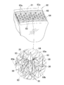
開口部40の内周面40Cには、第1面側20Aから第2面20B側へ複数の長繊維30が切断されずに延在している。具体的には、長繊維30は、第1面20A側において開口部40の第1開口端40Aからその外方へ延びる第1端部31と、第2面20B側において開口部40の第2開口端40Bからその外方へ延びる第2端部32と、第1及び第2端部31,32間において、開口部40の内周面40Cを縦断するように厚さ方向Zへ延びる中間部33とを有する。
図3(b)及び図4(b)を参照すると、生理用ナプキン10の着用状態において、排泄された体液は吸収性コア20において吸収、保持されて、吸収性コア20の厚さ寸法D1は、体液吸収前に比べて大きくなっている。具体的には、吸水性繊維25及びSAP粒子26に吸収されて膨潤するとともに、繊維間隙に一時的に体液が貯留されることによって、吸収性コア20は肉厚になる。
吸収体13は、着用状態において、着用者の鼠蹊部間に挟圧されることによって、吸収体13の両側縁部には内方へ向かう押圧力が作用し、吸収性コア20の全域に形成された複数の開口部40が崩れて、閉塞してしまうおそれがある。それに加えて、体液吸収後においては、体液を吸収・保持したSAP粒子26が膨潤してゲル化し、複数のSAP粒子26が寄せ集まって塊状になる。SAP粒子26がゲル化して塊状になることによって、塊状になった部分が開口部40に進入しようとしてその周縁部の形状が崩れて、排泄前の開口形状を保持することが困難になる。このように、着用者の鼠蹊部間による挟圧力とSAP粒子26の膨潤とによって開口部40の開口面積が小さくなって、吸収性コア20が所望の通気性及び変形容易性を発揮することができないおそれがある。
本実施形態においては、開口部40の内周面40Cにおいて、複数の長繊維30が切断されずに、厚さ方向Zにおいて第1面20Aと第2面20Bとに延在していることから、開口部40の内周面40Cの剛性が高くなって、その形状が崩れるのを抑制することができる。したがって、吸収体13が着用者の鼠蹊部間に挟圧されても開口部40がその形状を大きく崩すことはなく、SAP粒子26が塊状になって開口部40を閉塞しようとしても、長繊維30が開口部40へのSAP粒子26の進入を防いで開口部40が完全に閉塞されることはない。すなわち、開口部40が、その開口面積を一定程度維持できる程度に保形されることによって、吸収体13は、所望の通気性および変形容易性を発揮して、着用中における蒸れや身体への動きに対する追従性が低下するのを抑制することができる。
長繊維30は、開口部40の内周面40Cにおいて、直接的又は他の長繊維30を介して間接的に互いに交差していることが好ましい。図3(a)及び図4(a)を参照すると、長繊維30は、任意に選択した2つの長繊維30(第1及び第2長繊維)の中間部33どうしが直接的に互いに交差しているとともに、これら2つの長繊維30とは異なる単数又は複数の他の長繊維(第3長繊維)30の中間部33と間接的に交差している。長繊維30が内周面40Cにおいて、互いに直接的及び間接的に交差することによって、長繊維30によるネットワーク構造が形成される。このように、開口部40の内周面40Cに長繊維30によるネットワーク構造が形成されることによって、より高い保形性を発揮することができる。
ここで、長繊維30どうしが互いに交差するとは、吸収性コア20の厚さ方向において単に互いに重なることを意味することのほかに、繊維どうしが交絡することを含む。繊維どうしの交絡は、物理的に繊維が絡み合うことのほかに、製造時の熱処理によって熱可塑性樹脂繊維どうしが互いに熱溶着された交絡点を形成する場合を含む。本実施形態の長繊維30は、単なる交差、物理的な交絡及び溶着による交絡点のいずれの態様も含むものであって、長繊維30による強固なネットワーク構造を構成するためには、単なる交差部分よりも物理的に交絡している部分を多く含むことが好ましく、物理的に交絡した部分よりも熱溶着された交絡点を多く含むことがさらに好ましい。
また、長繊維30は、少なくとも一部において、内周面41Cに位置する中間部33のみではなく、第1面20A側に位置する第1端部31どうし及び/又は第2面側20B側に位置する第2端部32どうしが、直接的又は単数又は複数の他の長繊維30を介して間接的に互いに交差している。このように、厚さ方向(3次元方向)Zと平面方向(2次元方向)とにおいて、長繊維30どうしが互いに直接的又は他の長繊維を介して間接的に交差してネットワーク構造が形成されることから、厚さ方向Zにおいてのみ互いに交差する場合に比べて、より高い開口部40の保形性を発揮することができる。
長繊維30は、開口部40を効果的に保形するために、吸収性コア20全体にほぼ均一に配置されていることが好ましい。長繊維30が、吸収性コア20全体にほぼ均一に配置されていることによって、吸収性コア20が肉薄であっても比較的に高い剛性を有し、例えば、着用中に、縦方向Y及び/又は横方向Xから開口部40を閉塞しようとする力が作用したとしても、吸収性コア20全体でかかる力を受け止めて、開口部40が閉塞するのを抑制することができる。
また、長繊維30は、開口部40を効果的に保形するために、開口部40の開口縁部において他の領域に比べて密に配置されていてもよい。例えば、吸収性コア20に混合された長繊維30のうち、開口部40の内周面40C及びその周辺に位置する長繊維30が開口部40の保形に寄与しうるが、開口部40の周辺に位置していない長繊維30は開口部40の保形にあまり寄与するものではないともいえるので、比較的に疎に配置されていてもよい。
また、開口部40は、吸収性コア20全体に配置されているが、吸収性コア20の外周縁に沿う外周縁部には、配置されていない。このように、外周縁部に開口部40が形成されていないことによって、吸収体13が着用者の鼠蹊部間に挟圧されたときに、外周縁部に位置する開口部40の形状が崩れて外周縁部の折れ曲がり、外周縁部よりも内側に位置する開口部40の形状が連鎖的に崩れて閉塞されるのを抑制することができる。また、吸収性コア20の外周縁部には、吸収コア20の全体に配置されている開口部40とは異なる形状を有する、複数の条溝や複数の開孔が配置されていてもよい。かかる条溝や開孔は、吸収性コア20を貫通する貫通孔又は有底の凹状部分であり、着用時において着用者の身体に沿って吸収体13を変形させやすくするための変形誘導手段であって、本願発明の開口部40のように通気性に寄与するものではない。
開口部40の第1開口端40Aの開口面積と、第2開口端40Bの開口面積とは互いに異なっている。具体的には、開口部40は、厚さ方向Zにおいて、第1面20A側から第2面20B側へ向かって次第に幅広になるように、すなわち、第2面20B側から第1面20A側へ向かってテーパとなるように延びており、第1開口端40Aの開口面積は第2開口端40Bの開口面積よりも小さくなっている。第1面20A側が肌対向面側であることによって、比較的に開口面積の小さな第1開口端40Aが着用者の肌と対向することになるので、比較的に開口面積が大きな第2開口端40Bが対向する場合に比べて吸収体13と肌との接触面積が大きくなり、経血を吸収体13により多く取り込むことができる。また、着用時において、吸収体13を身体へ向かって凸曲するように宛がうためには、肌対向面側が変形しやすいように、比較的に開口面積が小さくて縮径しやすい第1開口端40Aが肌対向面側に位置していることが好ましい。
複数の開口部40は、吸収性コアを厚さ方向Zに実質的に貫通する貫通孔であるが、その製造工程において、開口部40からすべての長繊維30を排除することは困難であり、開口部40に僅かに長繊維30の一部が位置する場合を含む。図3(a)を参照すると、長繊維30の一部30aが、開口部40のうちの任意の開口部41を跨いでいる。このように、長繊維の一部30aが開口部41を跨ぐことによって、長繊維30によるネットワーク構造とともに、着用中に開口部41が潰されて閉塞するのを抑制するように作用することができる。また、長繊維30の一部30aには、パルプ繊維からなる吸水性繊維25が交絡されていてもよい。かかる場合には、長繊維30によるネットワーク構造がより強化されうる。
長繊維30は、熱可塑性樹脂繊維であって、平均繊維長が6~70mm、好ましくは15~40mmである。長繊維30の平均繊維長が6mm未満であると、任意の熱可塑性樹脂繊維が、他の熱可塑性樹脂繊維及び/又は吸水性繊維25と絡み難くなる傾向がある。平均繊維長が70mmを超える場合には、熱可塑性樹脂繊維の開繊性が著しく低下して、吸収体13がその一部に開繊されていない熱可塑性樹脂繊維を含むことによって、吸収体13の均一性が低下するおそれがある。
吸水性繊維25は主として平均繊維長が2~5mmのパルプ繊維であって、それが開口部40の内周面に位置することによって僅かながらにも開口部40の保形性にも寄与しうるが、一部の吸水性繊維25の長さ寸法は、開口部40の厚さ寸法D1よりも小さいことから、すべての吸水性繊維が開口部40の保形に寄与するものではない。一方、長繊維30は、吸水性繊維25よりも長く、かつ、少なくとも開口部40の厚さ寸法D1よりも長いことから、開口部40を縦断して第1開口端40Aの周辺及び第2開口端40Bの周辺まで延在することができる。
<平均繊維長の測定方法>
長繊維30の熱可塑性樹脂繊維、並びに吸水性繊維25のうちのパルプ繊維以外の繊維、例えば、再生セルロース繊維や半合成繊維の平均繊維長は、JIS L 1015:2010の附属書Aの「A7.1 繊維長の測定」の「A7.1.1 A法(標準法)目盛りが付いたガラス板上で個々の繊維の長さを測定する方法」に従って測定する。 なお、上記方法は、1981年に発行されたISO 6989に相当する試験方法である。また、パルプ繊維の平均繊維長は、重さ加重平均繊維長を意味し、メッツォオートメーション(metso automation)社製のカヤーニファイバーラボファイバープロパティーズ(オフライン)[kajaaniFiberLab fiber properties(off-line)]により測定されるL(w)値を意味する。
長繊維30の熱可塑性樹脂繊維、並びに吸水性繊維25のうちのパルプ繊維以外の繊維、例えば、再生セルロース繊維や半合成繊維の平均繊維長は、JIS L 1015:2010の附属書Aの「A7.1 繊維長の測定」の「A7.1.1 A法(標準法)目盛りが付いたガラス板上で個々の繊維の長さを測定する方法」に従って測定する。 なお、上記方法は、1981年に発行されたISO 6989に相当する試験方法である。また、パルプ繊維の平均繊維長は、重さ加重平均繊維長を意味し、メッツォオートメーション(metso automation)社製のカヤーニファイバーラボファイバープロパティーズ(オフライン)[kajaaniFiberLab fiber properties(off-line)]により測定されるL(w)値を意味する。
SAP粒子26の質量は、5~400g/m2、好ましくは、10~300g/m2である。SAP粒子26は、体液を吸収することによって自重の数十~数百倍に膨潤することから、開口部40を閉塞するように作用するものであって、できるだけその質量が低いことが好ましいが、SAP粒子26の質量が5g/m2未満であるには、吸収性コア20の吸収容量が低下して排泄された体液をすべて吸収、保持することができずに横漏れを生じるおそれがある。一方、SAP粒子26の質量が400g/m2を超える場合には、SAP粒子26のゲル化して塊状になる部分が比較的に多くなって、開口部40が長繊維30によるネットワーク構造に囲まれていたとしても、該塊状部分が開口部40の内周面40Cが型崩れするように進入して、閉塞してしまうおそれがある。
開口部40の1個当たりの面積は、12~150mm2である。開口部40の1個当たりの面積が12mm2未満の場合には、開口部40が比較的に小さくなり過ぎて着用中に閉塞してしまい、通気性が低下するおそれがある。一方、開口部40の1個当たりの面積が150mm2を超える場合には、開口部40が比較的に大きく見えて、着用者及び/又は着用補助者に対して、吸収体13の吸収性に対する不安感を与えるおそれがある。
吸収性コアの面積に対する複数の開口部の総面積の比率は、1~50%である。開口部40の面積は、従来の吸収性物品の吸収体(吸収性コア)に画成される開口部に比して大きく形成されており、それぞれの開口部40から確実に内部の空気を通過させることができるとともに、着用中における吸収性コア20の変曲点として機能しうる。開口部40が比較的に大きな面積を有することによって、長繊維30のネットワーク構造によって保形されつつ、着用者の股間部に挟圧されたり、SAP粒子の塊状部分に押し潰されて僅かに開口面積が縮小されても、完全に閉塞されることはない。
開口部40の開口面積が比較的に大きなことから、開口部40の外形輪郭を生理用ナプキン10の内面又は外面のうちの少なくとも一方の面から透視することができる。すなわち、開口部40の外形輪郭が比較的に大きいことから、コアラップシート21及び表面シート11を透過して生理用ナプキン10の内面から透視することができ、又は/及び、コアラップシート21及び裏面シート12を透過して生理用ナプキン10の外面から視認することができる。このように、生理用ナプキン10の内面又は/及び外面から開口部40の外形輪郭が視認されることから、着用者及び母親等の着用補助者に対して、生理用ナプキン10が通気性に優れる印象を与えることができる。また、規則的に配置された複数の開口部40の外形輪郭が視認されることによって、生理用ナプキン10の意匠性を向上させることができる。
開口部40は、同形同大状の各辺の長さが等しい矩形、すなわち、ほぼ正方形状であって、角部が先鋭状を有している。角部が先鋭状を有していることによって、それが曲状である場合に比べて、長繊維30がその周辺において屈曲した状態で位置することから、長繊維30どうしがより多く交絡してネットワーク構造を形成しやすくなる。
また、開口部40が正方形であることによって、吸収体13に対して着用時に鼠蹊部によって横方向Xの内側へ向かう力が作用しても、それと交差するように直線状に延びる両側辺によってかかる力を広く受け止めることができ、開口部40が閉塞するのを抑制することができる。加えて、複数の正方形状の開口部40の横方向Xへ延びる両端辺が、離間部分を介して互いに対向することによって、離間部分において身体形状に沿って縦方向Yに屈曲させることができる。
開口部40は、図示例と異なり、第1方向K1が縦断中心線P及び/又は横断中心線Qと並行するように配置されていてもよい。ただし、図示例のように、第1方向K1が縦断中心線P及び/又は横断中心線Qと傾斜するように延びていることによって、着用状態において、着用者が大腿部を動かしたときに生じる吸収体13に対して斜めに作用するそれを閉塞しようとする力を斜めに延びる両側辺によって受け止めることによって、開口部40が閉塞し難くなるといえる。
開口部40は、第1方向K1又は第2方向K2へ長い矩形状、すなわち、長方形状であってもよい。開口部40が、長方形状を有し、第1方向K1へ延びる辺の長さと第2方向K2へ延びる辺の長さとが互いに異なることによって、正方形である場合に比べて、より不規則に屈曲した状態で配置されて、長繊維30どうしがより多く交絡されるといえる。また、開口部40は、所要の技術的効果を発揮し得る限りにおいて、矩形状ではなく、円形、楕円形、菱形、多角形状であってもよい。
特に、開口部40が、菱形状の場合であって、開口部40の縦方向Yの寸法よりも横方向Xの寸法が大きい場合には、後記の製造方法によれば、横方向Xへ繊維が配向されやすくなるので、横方向Xに加えられる力によって開口部40が閉塞され難くなるといえる。一方、開口部40が菱形状の場合であって、開口部40の縦方向Yの寸法が横方向Xの寸法よりも大きい場合には、後記の製造方法によれば、縦方向Yへ繊維が配向されやすくなるので、開口部40は縦方向Yに対する剛性が向上して、例えば、着用者の膣口付近のフィット性を向上させることができる。さらに、開口部40は、同形同大状ではなく、互いに異なる大きさや形状であってもよく、例えば、各列50が、大小異なる大きさからなる矩形状と円形状の開口部40を組み合わせて形成されていてもよい。
既述のとおり、長繊維30は、複合繊維、例えば、芯部と、前記芯部よりも低い融点を有する鞘部とからなる芯鞘繊維から形成することができる。長繊維30が芯鞘繊維から形成される場合には、製造工程の熱付与処理において比較的に低い設定温度によって、熱可塑性樹脂繊維からなる長繊維30を捲縮させることができるとともに、長繊維30どうしを互いに交差する部分(交絡点)において互いに融着させることができる。長繊維30が捲縮することによって、互いに交絡しやすくなって、より強固なネットワーク構造を形成することができる。また、長繊維30が、捲縮率の互いに異なる複数種類の複合繊維を有していてもよい。かかる場合には、長繊維30どうしの捲縮度合いが異なることによって、不規則に交絡して、より強固なネットワーク構造を形成することができる。なお、製造工程の熱処理加工としては、例えば、吸収性コア20を賦形するために行う加圧・加熱加工、生理用ナプキン10の表面に施す熱エンボス加工等がある。これらの熱処理加工をすることによって、少なくとも吸収性コア20の熱処理加工された面に位置する長繊維30の一部が溶融される。
<吸収体の厚さ寸法の測定方法>
吸収体13(又は吸収性コア20)の厚さ寸法(mm)は、株式会社大栄科学精器製作所製 FS-60DS[測定面44mm(直径),測定圧3g/cm2]を準備し、標準状態(温度23±2℃,相対湿度50±5%)の下、吸収体13の異なる5つの部位を加圧し、各部位における加圧10秒後の厚さを測定し、5つの測定値の平均値を吸収体13の厚さ寸法とする。
吸収体13(又は吸収性コア20)の厚さ寸法(mm)は、株式会社大栄科学精器製作所製 FS-60DS[測定面44mm(直径),測定圧3g/cm2]を準備し、標準状態(温度23±2℃,相対湿度50±5%)の下、吸収体13の異なる5つの部位を加圧し、各部位における加圧10秒後の厚さを測定し、5つの測定値の平均値を吸収体13の厚さ寸法とする。
<通気抵抗値の測定方法>
吸収体13の厚さ方向Zにおける通気抵抗値について、KESカトーテック株式会社製の通気性試験機KES-F8-AP1を準備して、以下の手順による測定方法によって測定した。なお、通気抵抗値(kpa/s/m)が小さければ小さいほどに、より通気性に優れる。
吸収体13の厚さ方向Zにおける通気抵抗値について、KESカトーテック株式会社製の通気性試験機KES-F8-AP1を準備して、以下の手順による測定方法によって測定した。なお、通気抵抗値(kpa/s/m)が小さければ小さいほどに、より通気性に優れる。
(1)吸収体13を備えた吸収性物品(生理用ナプキン10又は使い捨ておむつ80)を標準雰囲気下(室温20℃、湿度60%RH)において24時間静置する。(2)生理用ナプキン10のサイドフラップ17等において伸長状態で収縮可能に弾性材料が取り付けられている場合には、それらの弾性材料を切断してその弾性作用を遮断し、生理用ナプキン10をその外面(非肌対向面)に形成されたギャザーがなくなる程度までに引っ張った状態で外面にアクリル板を貼りつける(3)比較的に大きな容器(トレー)に十分な量(例えば、容器内に生理用ナプキン10全体を30分間静置しても生理用ナプキン10の体積の約10倍程度の生理用食塩水が容器内に残る量)の生理食塩水を入れてアクリル板に貼りつけられた生理用ナプキン10全体を生理用食塩水に浸けて30分間静置した。(4)容器から生理用ナプキン10を取り出した後に、生理用ナプキン10をその内面(肌対向面)が試験台と対向するように載置して、外面に貼りつけられたアクリル板に吸収性コア20に均等に質量が掛かるように150mm×100mmの大きさの錘(5kg)を2つ配置して、20分間静置した。
(5)生理用ナプキン10の中央部分を直径90mmの円筒状の治具の大きさに合せてカットして、カットした部分から吸収体13(吸収性コア20と、コアラップシート21とを有する場合にはコアラップシート21を含む)のみを取り出して試料とし、試料を治具の底面に固定した。(6)治具を試験機にセットして、通気(空気)抵抗値を測定した。測定は、3回行い(試料ごとに1回ずつ)、その平均値を試料の通気抵抗値AR(kpa/s/m)として採用した。
下記表1は、実施例1~4の吸収体13及び比較例1~4の吸収体の通気抵抗値ARを上記測定方法によって測定した結果を示している。各実施例の吸収体13及び各比較例の吸収体は、吸収性コアと、それを包被する同一の材料から形成されたコアラップシートとから構成されている。
実施例1~4に係る吸収体13の吸収性コア20は、質量156gsmのSAP粒子26、質量180gsmの吸水性繊維25及び質量40gsmの長繊維30との混合物から構成されており、それぞれ、四角状の複数の開口部40が、千鳥状に同じ縦横ピッチで配置されている。第1~第4実施例において、開口部40全体の吸収性コア20の面積に対する開口率は45%であるが、開口部40の1辺の長さが、それぞれ、4mm、6mm、9mm、12mmで異なっている。
比較例1~3の吸収体の吸収性コアは、質量156gsmのSAP粒子、質量220gsmの吸水性繊維25の混合物から構成されており、長繊維を含んでいない。また、比較例1の吸収体の吸収性コアには開口部が形成されておらず、比較例2~比較例4の吸収体の吸収性コアには、実施例1~4と同様に、四角状の複数の開口部が千鳥状に同じ縦横ピッチで配置されている。また、比較例2~4において、開口部40全体の吸収性コア20の面積に対する開口率は45%であるが、開口部の一遍の長さが、それぞれ、4mm、6mm、9mmで異なっている。
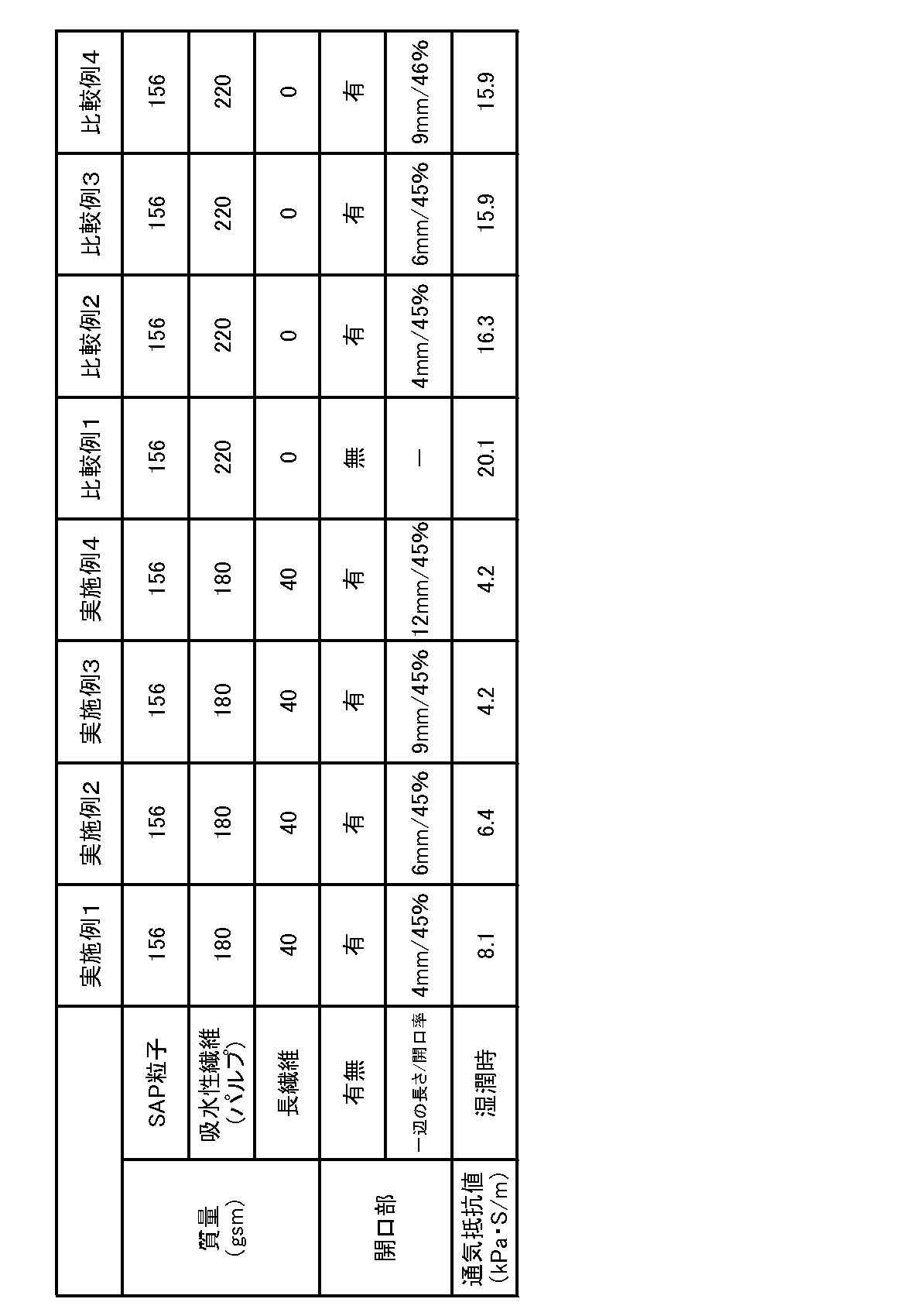
表1の測定結果を参照すると、実施例1~3の吸収体13の湿潤状態の通気抵抗値がそれぞれ、8.1、6.4、4.2であるのに対し、開口部を有しない吸収体である比較例1の通気抵抗値は20.1である。したがって、湿潤時における、複数の開口部40を有する吸収体13の通気抵抗値は、複数の開口部を有しない吸収体の通気抵抗値の50%未満であるといえる。上記測定方法においては、各吸収体において所定の面積を有する所定領域について通気抵抗値を測定していることから、かかる測定結果は、湿潤状態における、開口部40を有する所定領域の通気抵抗値は、開口部40を有しない所定領域の通気抵抗値の50%未満であると言い換えることができる。
乾燥状態において、複数の開口部40を有する所定領域の通気抵抗値が開口部40を有しない所定領域の通気抵抗値よりも低いことは当然であるが、湿潤状態においても、前者の通気抵抗値が後者の通気抵抗値の50%未満であって、依然として比較的に低い通気抵抗値を維持していることから、乾燥状態のみならず、湿潤状態においても通気性に優れるものといえる。
比較例2と実施例1とを比較すると、開口部40の一辺の長さが同じ5mm以上であって、具体的には6mmであって、その開口率も同じであるにも関わらず、実施例1の通気抵抗値は比較例2の通気抵抗値の約50%の大きさである。これは、実施例1の吸収性コア20が長繊維30を含むとともに、長繊維30が開口部40の内周面40Cに位置して、第1面20A側から第2面20B側へ延在しており、かつ、長繊維30の少なくとも一部において平面方向及び/又は厚さ方向において互いに交差してネットワーク構造を形成していることから、SAP粒子26が膨潤しても開口部40が型崩れすることなく、その形状を維持していることによるものであると考えられる。
<吸収体の最大引張強度の測定方法>
吸収体13の乾燥状態、湿潤状態における縦方向Yの最大引張強度(引張強度)を以下の測定方法によって求めた。
吸収体13の乾燥状態、湿潤状態における縦方向Yの最大引張強度(引張強度)を以下の測定方法によって求めた。
(1)吸収性物品(生理用ナプキン10又は使い捨ておむつ80)から吸収体13を取り出して、吸収体13を縦方向Yが長手方向となるように長さ150mm×幅60mmの大きさにカットして試料を得て、試料を標準雰囲気下(室温20℃、湿度60%RH)において24時間静置する。(2)公知の引張試験機(株式会社島津製作所製,AG-1kN1)を用いて、チャック間隔100mm、引張速度100mm/分で試料が切断されるまで荷重(最大点荷重)を加えて、最大引張強度(N/60mm)を測定する。なお、「N/60mm」は、試料の長手方向における幅60mm当たりの最大引張強度(N)を意味しており、サイズ的に生理用ナプキン10から当該幅寸法を採取することができない場合には、測定結果を幅60mmに換算したものとする。また、乾燥状態及び湿潤状態の吸収体13の最大引張強度の測定に関し、上記で特に規定しない測定条件等については、ISO9073-3又はJISL1913 6.3に記載の測定条件を適宜採用する。
各試料について、上記の測定を5回行い、その平均値を乾燥状態の吸収体13の最大引張強度(N/60mm)とした。一方、湿潤状態における吸収体13の最大引張強度については、試料の中央部に6mlの人工尿(生理食塩水)を滴下して1分間放置した後に、乾燥状態における最大引張強度の測定方法と同様の方法によって、最大引張強度を求めた。
ここで、吸収体がパルプ繊維のみから形成される場合には、比較的に引張強度は低くなるといえる。かかる吸収体において体液が吸収されて湿潤状態となったときには、パルプ繊維が水分を吸収して膨潤し、繊維間隙が小さくなって繊維どうしの摩擦が生じることによって、開口部が閉じる方向(径方向の内側に向かって)にパルプ繊維が膨潤しやすく通気性が低下するおそれがあり、かつ、引張強度の低下は生じ難いといえる。また、吸収体がパルプ繊維とSAP粒子との混合物から形成される場合には、吸収体の湿潤状態において、SAP粒子の膨潤する力がパルプ繊維どうしの摩擦する力よりも大きくなることから、繊維長の比較的に小さなパルプ繊維間に距離が生じて繊維間隙が生じやすくなるために、開口部が閉じる方向に膨潤しやすく通気性が低下するおそれがあり、かつ、湿潤時には引張強度が低下してしまうおそれがある。
本発明に係る吸収体13は、パルプ繊維からなる吸水繊維25と、SAP粒子26及び長繊維30との混合物から形成されていることから、湿潤状態において、SAP粒子26が膨潤したとしても長繊維30が比較的に大きな繊維長を有し、繊維どうしが互いに絡み合った状態が維持されやすい。したがって、前記2つの吸収体の構成例と比べて、開口部40が閉じる方向には膨潤し難く、かつ、引張強度は低下し難くなるといえる。さらに、吸収体13の賦形時及び/又は圧搾溝を形成するときに熱処理を施すことによって、熱可塑性樹脂繊維からなる長繊維30どうしが交点において互いに融着される。かかる融着部分が複数形成されることによって、引張強度はさらに低下し難くなるといえる。
吸収性物品は、着用状態において、外面に位置する止着域を介して下着等の内面に取り付けられた態様で着用者の身体に沿うように縦方向Yへ伸長された状態となるが、このように、吸収体13は、厚さ方向Zに貫通する複数の開口部40が形成されているにも関わらず、乾燥状態において比較的に高い引張強度を有することから、体液が排泄される前に、吸収体13がよれてしまうことはない。また、湿潤状態においても、乾燥状態と同様に、体液が排泄された後でも吸収体13がよれてしまうことはない。
本発明に係る吸収性コア20の製造方法についていえば、この種の分野において慣用された製法を用いることができ、例えば、以下のような方法によって製造することができる。
吸収性コア20の製造装置は、ダクトと、ダクトと対向して位置する、周面に凹状の型枠を有する成型ドラムとを備え、ダクトの上流に位置する各供給経路を経て、SAP粒子26、長繊維(熱可塑性樹脂樹脂)30及び吸水性繊維25が、ダクト内部に供給される。ダクト内部では、成型ドラムのサクション機構を介してダクトの流入口からその流出口へ向かって空気が吸引されている。SAP粒子26、長繊維30及び吸水性繊維25は、気流に乗ってダクト内部を飛動して混合されてコア材料となって、流出口へ向かって移動する。
回転する成型ドラムがダクトの流出口と対向するとサクション機構を介して空気が型枠からドラムの内部へ向かって吸引されるので、混合されたコア材料64が型枠に堆積する。型枠の底面には複数の突起部が配置されており、突起部にはコア材料64が堆積されない。その後、型枠に堆積されたコア材料64は、サクション機構の吸引力によって型枠内に保持されながら成型ドラムの回転によってコンベアに近づき、コンベアと対向したときにコンベアの下方に位置するサクション機構の吸引力でコア材料64が型枠からコンベアに引き取られる。その後、コア材料64は、走行するコンベアによって加圧・加熱圧縮工程において圧縮されて、吸収性コア20となる。
図5は、吸収性コア20の製造装置の一例における、成型ドラム60の一部拡大図である。成型ドラム60は、その外周面において周方向に並ぶ複数の型枠61と、型枠61の底面62に位置する複数の突起部63とを備え、突起部63は、上方へ向かって次第に幅狭となる先鋭(テーパ)状を有する。コア材料64が成型ドラム60の型枠61に上方から堆積するときに、型枠61の底面62に位置する複数の突起部63には堆積されないことによって、吸収性コア20に複数の開口部40を形成することができる。また、突起部63が上方へ向かう先鋭状であることから、ダクトから突起部63上に向かう長繊維30は、突起部63の先端63aに当たってその周辺に跳ねよけられ、又は突起部63の周面63bに沿うように底面62に向かって下方へ延びる。その結果、型枠61内に堆積されたコア材料64において長繊維30は、突起部63を囲むようにその周辺に位置し、かつ、それらの一部が突起部63の周面63bと対向する部分(開口部40の内周面40Cに相当)において、直接的又は間接的に互いに交差する。図示した突起部63以外の複数の突起部63aにおいても同様に、長繊維30が突起部63の周面63bに沿って位置している。かかる製法においては、例えば、突起部63の形状を先鋭状にしてその周辺により跳ねよけさせることで長繊維30どうしを交差させてネットワーク構造を形成してもよい。突起部63の形状を先鋭状にすること、または/それに加えて、ダクト内でSAP粒子26と混在される前に、長繊維30と吸水性繊維25とを搬送路において比較的に長い時間混合させた状態とすることによって長繊維30どうし、長繊維30と吸水性繊維25とが互いによくブレンドされて絡み合わせることで、成型ドラムの型枠に堆積するときに、絡み合った状態を維持させてもよい。
また、他の製造方法としては、例えば、上記の製造工程において、成型ドラム60の型枠61の底面62に複数の突起部63を配置せずに、コア材料64が成型ドラム60からコンベアに引き取られた後、圧縮工程の前又はその後において、複数の先鋭状のピンでコア材料64の長繊維30を切断することなく、掻き分けるようにして挿し入れて引き抜くことによって、複数の開口部40を形成することができる。かかる場合においても、先鋭状のピンで掻き分けられた長繊維30が、平面視において、開口部40を囲むようにその周辺に位置し、かつ、各開口部40の周辺に位置する長繊維30どうしが互いに直接的又は間接的に互いに交差しうる。ただし、かかる製法では、長繊維30が実質的に切断されることなく吸収性コア20に先鋭状のピンを挿し入れて複数の開口40を形成するために、長繊維30の質量、分布範囲、分布面積、開口部40の大きさや開口率、吸収性コア20のコンベア上の搬送速度やピンの挿入速度等のすべての諸条件を適宜調整する必要がある。
図6は、本発明に係る吸収性物品用の吸収体13の使用例の一例を示すものであって、本使用例においては、吸収体13は、使い捨ておむつ(吸収性物品)80に使用されている。使い捨ておむつ80は、前後ウエストパネル84,85の両側縁部を接合するサイドシームを剥離して、横方向及び縦方向へ伸展した状態を示されている。
使い捨ておむつ80は、前ウエスト域81と、後ウエスト域82と、前後ウエスト域81,82間に位置するクロッチ域83とを有する。また、おむつ80は、前ウエスト域81とクロッチ域83の一部を画成する前ウエストパネル84と、後ウエスト域82とクロッチ域83の一部を画成する後ウエストパネル85と、前後ウエストパネル84,85の肌対向面側において縦方向へ延びる吸液構造体86とを備え、前後ウエストパネル84,85の両側縁部どうしが互いに重ね合された状態において、縦方向へ間隔を空けて配置された複数のシーム部を介して互いに接合されることによって、ウエスト開口と一対のレッグ開口とが画成される。吸収体13は、吸液構造体86内においてクロッチ域83から前後ウエスト域81,82に延在している。
おむつ80は、予め前後ウエスト域81,82の両側縁部が接合された、いわゆるパンツ型であって、生理用ナプキン10と同様に、着用状態において、クロッチ域83に位置する吸収体13は着用者の鼠蹊部間に挟圧されるとともに、排泄後に、体液を吸収したSAP粒子が膨潤してゲル化して塊状部分が形成されて開口部40の形状が崩されるおそれがあるが、長繊維30が開口部40の内周面40Cにおいてネットワーク構造を形成することによって、開口部40を保形して所要の通気性及び変形容易性を発揮することができる。なお、本発明に係る吸収性物品としては、パンツ型おむつだけではなく、開放型おむつであってもよい。
図7を参照すると、使い捨ておむつ80の吸収体13に形成された開口部40において、第1面20A(肌対向面)側に位置する第1開口端40Aの面積が、第2面20B(非肌対向面)側に位置する第2開口端40Bの面積よりも大きくなっている。したがって、開口部40は、厚さ方向Zにおいて、第1面20A側から第2面20B側へ向かって次第に幅狭となるようにテーパ状を有している。吸収体13がかかる構成を有することによって、肌対向面側から開口部40に進入した尿等の体液は、非肌対向面側へ速やかに移動されることから、肌対向面側に体液が比較的に長時間滞留して肌に触れて、着用者に不快感を与えるのを抑制することができる。さらに、開口部40の内周面40Cに位置する長繊維30は、第1開口端40Aから第2開口端40Bへ向かって次第に密になるように寄せ集められることから、内周面40Cの強度が局所的により向上しうる。
吸収性物品10,80を構成する部材には、特に明記されていない限りにおいて、本明細書に記載されている材料のほかに、この種の分野において通常用いられている公知の材料を制限なく用いることができる。また、本明細書において使用されている「第1」及び「第2」等の用語は、同様の要素、位置等を単に区別するために用いてある。
10 生理用ナプキン(吸収性物品)
13 吸収体
20 吸収性コア
20A 第1面
20B 第2面
25 吸水性繊維
26 超吸収性ポリマー粒子(SAP粒子)
30 長繊維
30a 長繊維の一部
31 第1端部
32 第2端部
33 中間部
40 開口部
40C 開口部の内周面
41 第1開口端
42 第2開口端
80 使い捨ておむつ(吸収性物品)
Z 厚さ方向
13 吸収体
20 吸収性コア
20A 第1面
20B 第2面
25 吸水性繊維
26 超吸収性ポリマー粒子(SAP粒子)
30 長繊維
30a 長繊維の一部
31 第1端部
32 第2端部
33 中間部
40 開口部
40C 開口部の内周面
41 第1開口端
42 第2開口端
80 使い捨ておむつ(吸収性物品)
Z 厚さ方向
Claims (12)
- 吸収性物品用の吸収体であって、
厚さ方向と、前記厚さ方向において互いに対向する第1面と第2面とを有する吸収性コアと、前記吸収性コアを前記厚さ方向へ実質的に貫通する複数の開口部とを有し、
前記吸収性コアが、吸水性繊維と、前記吸水性繊維よりも長い長繊維を含み、
前記長繊維が、前記厚さ方向において、前記開口部の内周面に位置し、前記第1面から前記第2面へ切断されずに延在していることを特徴とする前記吸収体。 - 吸収性物品用の吸収体であって、
前記吸収体が、厚さ方向と、吸収性コアと、前記吸収性コアを実質的に貫通する複数の開口部とを有し、
前記吸収性コアが、吸水性繊維と、高吸収性ポリマー粒子と、前記吸水性繊維よりも長い長繊維とを含み、
前記開口部の面積が12mm2以上であって、
湿潤状態における、前記吸収体の前記開口部を含む領域の通気抵抗値が、前記開口部を含まない領域の通気抵抗値の50%以下であることを特徴とする前記吸収体。 - 前記長繊維は、前記開口部の内周面において互いに直接的又は間接的に交差している請求項1又は2に記載の吸収体。
- 前記長繊維は、前記吸収性コアの全体において均一に配置されている請求項1~3のいずれかに記載の吸収体。
- 前記長繊維は、前記開口部の開口縁部において他の領域に比べて密に配置されている請求項1~4のいずれかに記載の吸収体。
- 前記吸収性コアの外周縁部には、前記開口部が配置されていない請求項1~5のいずれかに記載の吸収体。
- 前記開口部の前記第1面に位置する第1開口端の面積が、前記第2面に位置する第2開口端の面積と異なる請求項1,3~6のいずれかに記載の吸収体。
- 前記開口部は、前記吸収性物品の内面及び外面のうちの少なくとも一方の面から透視される請求項1~7のいずれかに記載の吸収体。
- 前記長繊維の一部が、前記開口部を跨いでいる請求項1~8のいずれかに記載の吸収体。
- 前記長繊維は、熱可塑性樹脂繊維であって、平均繊維長が6~70mmである請求項1~9のいずれかに記載の吸収体。
- 前記長繊維は、互いに交差する部分において熱融着されている請求項10に記載の吸収体。
- 前記開口部の1個当たりの面積は、12~150mm2であって、前記吸収性コアの面積に対する複数の前記開口部の総面積の比率は、1~50%である請求項1~11のいずれかに記載の吸収体。
Priority Applications (1)
| Application Number | Priority Date | Filing Date | Title |
|---|---|---|---|
| PCT/JP2018/018932 WO2019220569A1 (ja) | 2018-05-16 | 2018-05-16 | 吸収性物品用の吸収体 |
Applications Claiming Priority (1)
| Application Number | Priority Date | Filing Date | Title |
|---|---|---|---|
| PCT/JP2018/018932 WO2019220569A1 (ja) | 2018-05-16 | 2018-05-16 | 吸収性物品用の吸収体 |
Publications (1)
| Publication Number | Publication Date |
|---|---|
| WO2019220569A1 true WO2019220569A1 (ja) | 2019-11-21 |
Family
ID=68539876
Family Applications (1)
| Application Number | Title | Priority Date | Filing Date |
|---|---|---|---|
| PCT/JP2018/018932 Ceased WO2019220569A1 (ja) | 2018-05-16 | 2018-05-16 | 吸収性物品用の吸収体 |
Country Status (1)
| Country | Link |
|---|---|
| WO (1) | WO2019220569A1 (ja) |
Citations (3)
| Publication number | Priority date | Publication date | Assignee | Title |
|---|---|---|---|---|
| JPS61125343A (ja) * | 1984-11-20 | 1986-06-13 | ユニ・チヤ−ム株式会社 | 吸収性物品の表面材およびその製法 |
| JP2002345887A (ja) * | 2001-05-29 | 2002-12-03 | Uni Charm Corp | 吸収性物品 |
| JP2014155600A (ja) * | 2013-02-15 | 2014-08-28 | Oji Holdings Corp | 吸収性物品 |
-
2018
- 2018-05-16 WO PCT/JP2018/018932 patent/WO2019220569A1/ja not_active Ceased
Patent Citations (3)
| Publication number | Priority date | Publication date | Assignee | Title |
|---|---|---|---|---|
| JPS61125343A (ja) * | 1984-11-20 | 1986-06-13 | ユニ・チヤ−ム株式会社 | 吸収性物品の表面材およびその製法 |
| JP2002345887A (ja) * | 2001-05-29 | 2002-12-03 | Uni Charm Corp | 吸収性物品 |
| JP2014155600A (ja) * | 2013-02-15 | 2014-08-28 | Oji Holdings Corp | 吸収性物品 |
Similar Documents
| Publication | Publication Date | Title |
|---|---|---|
| JP5064568B2 (ja) | 吸収性コア | |
| AU2014208105B2 (en) | Absorbent article | |
| RU2676441C2 (ru) | Способ формирования растягивающейся структуры для впитывающего изделия и растягивающаяся структура для впитывающего изделия | |
| AU2003248449C1 (en) | Thin comfortable sanitary napkin having reduced bunching | |
| CN101018523B (zh) | 具有改进的采集速率的吸收产品 | |
| JPH05237150A (ja) | 吸収性物品用身体側カバー | |
| JP6486013B2 (ja) | 吸収性物品 | |
| JP2009519099A (ja) | 吸収性用品 | |
| TWI880988B (zh) | 吸收性物品 | |
| JP4540629B2 (ja) | 吸収性物品 | |
| JP7412979B2 (ja) | 吸収性物品、及び、吸収性物品の製造方法 | |
| TWI794565B (zh) | 吸收性物品 | |
| CN113633471A (zh) | 一种吸收性用品及其制造方法 | |
| RU2763716C2 (ru) | Впитывающий элемент и впитывающее изделие | |
| JP7150687B2 (ja) | 吸収性物品 | |
| WO2024070275A1 (ja) | 吸収性物品及びこれに用いる吸収要素の製造方法 | |
| TWI828820B (zh) | 吸收體及吸收性物品 | |
| JP7050909B2 (ja) | 吸収性物品用の吸収体 | |
| JP7323997B2 (ja) | 吸収性物品 | |
| JP2020188918A (ja) | 吸収性物品 | |
| CN112135593B (zh) | 吸收性物品 | |
| JP2020188919A (ja) | 吸収性物品 | |
| JP7453180B2 (ja) | 使い捨ておむつとその製造方法 | |
| JP7412978B2 (ja) | 吸収性物品 | |
| JP2020028676A (ja) | 吸収体 |
Legal Events
| Date | Code | Title | Description |
|---|---|---|---|
| 121 | Ep: the epo has been informed by wipo that ep was designated in this application |
Ref document number: 18918905 Country of ref document: EP Kind code of ref document: A1 |
|
| NENP | Non-entry into the national phase |
Ref country code: DE |
|
| 122 | Ep: pct application non-entry in european phase |
Ref document number: 18918905 Country of ref document: EP Kind code of ref document: A1 |
|
| NENP | Non-entry into the national phase |
Ref country code: JP |