WO2019220565A1 - 油圧システム - Google Patents
油圧システム Download PDFInfo
- Publication number
- WO2019220565A1 WO2019220565A1 PCT/JP2018/018925 JP2018018925W WO2019220565A1 WO 2019220565 A1 WO2019220565 A1 WO 2019220565A1 JP 2018018925 W JP2018018925 W JP 2018018925W WO 2019220565 A1 WO2019220565 A1 WO 2019220565A1
- Authority
- WO
- WIPO (PCT)
- Prior art keywords
- pump
- control valves
- pressure
- valve
- tank
- Prior art date
- Legal status (The legal status is an assumption and is not a legal conclusion. Google has not performed a legal analysis and makes no representation as to the accuracy of the status listed.)
- Ceased
Links
Images


Classifications
-
- F—MECHANICAL ENGINEERING; LIGHTING; HEATING; WEAPONS; BLASTING
- F15—FLUID-PRESSURE ACTUATORS; HYDRAULICS OR PNEUMATICS IN GENERAL
- F15B—SYSTEMS ACTING BY MEANS OF FLUIDS IN GENERAL; FLUID-PRESSURE ACTUATORS, e.g. SERVOMOTORS; DETAILS OF FLUID-PRESSURE SYSTEMS, NOT OTHERWISE PROVIDED FOR
- F15B11/00—Servomotor systems without provision for follow-up action ; Circuits therefor
Definitions
- the present invention relates to a load sensing type hydraulic system.
- load sensing type hydraulic systems have been adopted in construction machines and industrial vehicles.
- the discharge flow rate of the variable displacement pump is adjusted so that the differential pressure between the discharge pressure of the pump and the maximum load pressure of the plurality of hydraulic actuators is constant.
- Patent Document 1 discloses a load sensing type hydraulic system configured such that even when all of a plurality of control valves for a plurality of hydraulic actuators are in a neutral state, hydraulic fluid flows through a valve unit including the control valves. It is disclosed. As a result, the valve unit is also warmed during standby when all the control valves are in a neutral state, and a decrease in responsiveness under low temperature conditions is suppressed.
- a relief valve and an unload valve are arranged downstream of a plurality of control valves.
- the relief valve defines a circuit upper limit pressure.
- the unloading valve allows the hydraulic fluid to flow from the pump to the tank when the plurality of control valves are not operated, and allows the hydraulic fluid to flow from the pump to the tank when at least one of the plurality of control valves is operated. It inhibits.
- the valve unit has a main flow path that passes through a plurality of control valves, and a relief valve and an unload valve are provided in parallel on the downstream side of the plurality of control valves in the main flow path.
- the minimum discharge flow rate of the pump is mechanically set to a value larger than zero. For this reason, at the time of standby, the hydraulic fluid at a constant flow rate is discharged from the pump, and the hydraulic fluid flows into the tank through the plurality of control valves and the unload valve.
- the relief valve when the relief valve is arranged on the downstream side of the plurality of control valves as in the hydraulic system of Patent Document 1, the distance from the pump to the relief valve becomes long, so the pressure loss corresponding to the distance is increased.
- the relief pressure of the relief valve must be set lower than the circuit upper limit pressure. Note that the pressure loss used to determine the relief pressure is calculated based on the maximum discharge flow rate of the pump.
- an object of the present invention is to make it possible to increase the pump discharge pressure to the circuit upper limit pressure or in the vicinity thereof even when the pump discharge flow rate is small when the hydraulic actuator is operated.
- the present invention provides a variable displacement pump, a valve unit including a plurality of control valves for a plurality of hydraulic actuators, a discharge pressure of the pumps, and a maximum load pressure of the plurality of hydraulic actuators.
- a regulator that adjusts the discharge flow rate of the pump so that the differential pressure is constant, a regulator in which the minimum discharge flow rate is mechanically set to a value larger than zero, and upstream of the plurality of control valves
- the relief valve that regulates the circuit upper limit pressure and the downstream of the plurality of control valves are allowed to flow from the pump to the tank when the plurality of control valves are not operated.
- an unload valve that inhibits the flow of hydraulic fluid from the pump to the tank when at least one of the plurality of control valves is operated.
- the relief valve is arranged on the upstream side of the plurality of control valves, the distance from the pump to the relief valve is shortened. Accordingly, the pressure loss corresponding to the distance is reduced, and the relief pressure of the relief valve can be made substantially equal to the circuit upper limit pressure. As a result, even when the pump discharge flow rate is small when the hydraulic actuator is operated, the pump discharge pressure can be increased to the circuit upper limit pressure or the vicinity thereof.
- the valve unit extends from an inlet connected to the pump by a supply line, an outlet connected to a tank by a carry-over line, and the plurality of control valves from the inlet to the outlet.
- You may have a main flow path and the some distribution path which connects the said main flow path with the said some control valve. According to this configuration, the flow channel area of the main flow channel can be made relatively large, and the pressure loss from the inlet to the outlet of the valve unit can be made relatively small.
- the relief valve is provided in a tank line that branches from the main flow path on the upstream side of the plurality of distribution channels or branches from the supply line, and the unload valve is provided in the carry-over line. May be.
- the discharge pressure of the pump can be increased to the circuit upper limit pressure or the vicinity thereof.
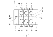
- FIG. 1 is a schematic configuration diagram of a hydraulic system according to an embodiment of the present invention. It is a schematic block diagram of a regulator. It is a top view of a valve unit.
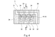
- FIG. 4 is a sectional view taken along line IV-IV in FIG. 3.
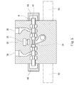
- FIG. 5 is a sectional view taken along line VV in FIG. 4.
- FIG. 1 shows a load sensing type hydraulic system 1 according to an embodiment of the present invention.
- the hydraulic system 1 is mounted on a construction machine or an industrial machine such as a tractor or a hydraulic excavator, for example.
- the hydraulic system 1 includes a variable displacement pump 21, a plurality of hydraulic actuators 5, and a valve unit 3 interposed between the pump 21 and the hydraulic actuator 5.
- each hydraulic actuator 5 is a hydraulic cylinder, but each hydraulic actuator 5 may be a hydraulic motor.
- the number of hydraulic actuators 5 is three, but the number of hydraulic actuators 5 can be changed as appropriate.
- the valve unit 3 includes a plurality of control valves 4 (the same number as the hydraulic actuators 5) for the hydraulic actuator 5.
- Each control valve 4 is connected to a corresponding hydraulic actuator 5 by a pair of supply / discharge lines 37, and controls supply and discharge of hydraulic fluid to the hydraulic actuator 5.
- valve unit 3 has an inlet 31, an outlet 32 and a main flow path 33.
- the main flow path 33 extends from the inlet 31 to the outlet 32 so as not to pass through all the control valves 4.
- the main flow path 33 is connected to the control valve 4 by a plurality (the same number as the control valves 4) of distribution paths 34 so that all the control valves 4 are arranged in parallel.
- Each distribution path 34 is provided with a pressure compensation valve 35.
- the valve unit 3 includes a first block 3A in which an inflow port 31 is formed, a second block 3B in which an outflow port 32 is formed, and a first block 3A.
- a plurality of intermediate blocks 3C sandwiched between the second blocks 3B are included.
- the main flow path 33 is extended so that all the blocks 3A, 3B, 3C may be crossed.
- Each control block 4 is incorporated in each intermediate block 3C. That is, the number of intermediate blocks 3 ⁇ / b> C is equal to the number of control valves 4, and each intermediate block 3 ⁇ / b> C is formed with a pair of supply / discharge ports 36 located in the middle of the supply / discharge line 37.
- each control valve 4 includes a spool 41 having a plurality of land portions, a pair of springs 42 that urge the spool 41 toward both sides in the axial direction, and one spool 41 in the axial direction. Or it includes a pair of driving means 43 for driving the other.
- the spring 42 is omitted for simplification of the drawing.
- each driving means 43 applies a pilot pressure to the spool 41 to drive the spool 41.
- each drive means 43 is not restricted to this, For example, an electromagnetic linear motion mechanism may be sufficient.
- the spool 41 passes through the intermediate block 3C, and both ends of the spool 41 are exposed from both side surfaces of the intermediate block 3C. Covers 44 that cover both ends of the spool 41 are attached to both side surfaces of the intermediate block 3C.
- the main flow path 33 is located at a position slightly away from the spool 41 toward the supply / discharge port 36 in the region crossing all the intermediate blocks 3 ⁇ / b> C. It extends straight in a direction perpendicular to the direction.
- the inlet 31 of the valve unit 3 is connected to the pump 21 via the supply line 11, and the outlet 32 of the valve unit 3 is connected to the tank via the carryover line 12.
- Relief valves 62 are arranged upstream of all the control valves 4, and unload valves 13 are arranged downstream of all the control valves 4. That is, the carry over line 12 is connected to the tank via the unload valve 13.
- the discharge flow rate of the pump 21 is adjusted by the regulator 22.
- a discharge pressure Pd of the pump 21 is guided to the regulator 22 through the first signal pressure line 23, and a maximum load pressure PL of the hydraulic actuator 5 is guided through the second signal pressure line 24.
- the regulator 22 adjusts the discharge flow rate of the pump 21 so that the differential pressure between the discharge pressure Pd of the pump 21 and the maximum load pressure PL becomes constant.
- the regulator 22 resists the swash plate 21 a of the pump 21 in the direction in which the discharge flow rate increases and the swash plate 21 a of the pump 21 against the urging force of the spring 72. And a piston 71 that presses in a direction in which the discharge flow rate decreases.
- the regulator 22 includes a differential pressure adjusting valve 76 and a cut-off valve 75 that adjust the control pressure guided to the pressure receiving chamber 74 for the piston 71.
- the differential pressure adjustment valve 76 adjusts the control pressure so that the differential pressure between the discharge pressure Pd of the pump 21 and the maximum load pressure PL is constant, and the cut-off valve 75 sets the discharge pressure Pd of the pump 21 to the set value. Adjust the control pressure so that it does not exceed.
- the minimum discharge flow rate of the pump 21 is mechanically set to a value larger than zero. That is, the regulator 22 is provided with a stopper 73 that limits the amount of movement of the piston 71.
- the relief valve 62 described above defines the circuit upper limit pressure.
- the relief valve 62 is provided in the tank line 61 branched from the main flow path 33 of the valve unit 3 and connected to the tank on the upstream side of all the control valves 4.
- the tank line 61 may branch from the supply line 11.
- the relief valve 62 is incorporated in the first block 3A of the valve unit 3. However, in FIG. 3, the relief valve 62 is omitted for simplification of the drawing.
- the unload valve 13 allows the flow of hydraulic fluid from the pump 21 to the tank through the carryover line 12 when all the control valves 4 are not operated, and the pump 21 when at least one of the control valves 4 is operated.
- the unload valve 13 blocks the carryover line 12 when the differential pressure between the pressure Pt of the carryover line 12 and the maximum load pressure PL is equal to or lower than a set value, and the pressure Pt of the carryover line 12 When the pressure difference with the maximum load pressure PL is larger than the set value, the carry-over line 12 is opened (the upstream portion of the carry-over line 12 is communicated with the downstream portion).
- the relief valves 62 are arranged on the upstream side of all the control valves 4, the distance from the pump 21 to the relief valves 62 is shortened. Therefore, the pressure loss corresponding to the distance is reduced, and the relief pressure of the relief valve 62 can be made substantially equal to the circuit upper limit pressure. As a result, even when the discharge flow rate of the pump 21 is small when the hydraulic actuator 5 is operated, the discharge pressure Pd of the pump 21 can be increased to the circuit upper limit pressure or the vicinity thereof.
- the valve unit can be used even during standby when all the control valves 4 are in a neutral state.
- the hydraulic fluid flows to 3 and the valve unit 3 is warmed. Thereby, the fall of the responsiveness under low temperature conditions can be suppressed.
- the main flow path 33 may extend from the inlet 31 to the outlet 32 so as to pass through all the control valves 4.
- the flow area of the main flow path 33 can be made relatively large.
- the pressure loss from the inlet 31 to the outlet 32 of the valve unit 3 can be made relatively small.
Landscapes
- Engineering & Computer Science (AREA)
- Physics & Mathematics (AREA)
- Fluid Mechanics (AREA)
- Mechanical Engineering (AREA)
- General Engineering & Computer Science (AREA)
- Fluid-Pressure Circuits (AREA)
Abstract
油圧システムは、可変容量型のポンプと、複数の油圧アクチュエータ用の複数の制御弁を含むバルブユニットと、ポンプの吐出圧と複数の油圧アクチュエータの最高負荷圧との差圧が一定となるようにポンプの吐出流量を調整するレギュレータであって、最小吐出流量がゼロよりも大きな値に機械的に設定されたレギュレータと、複数の制御弁の上流側に配置された、回路上限圧を規定するリリーフ弁と、複数の制御弁の下流側に配置された、複数の制御弁が操作されないときにポンプからタンクへの作動液の流通を許容し、複数の制御弁の少なくとも1つが操作されるときにポンプからタンクへの作動液の流通を阻害するアンロード弁と、を備える。
Description
本発明は、ロードセンシング方式の油圧システムに関する。
従来から、建設機械や産業車両などでは、ロードセンシング方式の油圧システムが採用されている。ロードセンシング方式の油圧システムでは、ポンプの吐出圧と複数の油圧アクチュエータの最高負荷圧との差圧が一定となるように、可変容量型のポンプの吐出流量が調整される。
例えば、特許文献1には、複数の油圧アクチュエータ用の複数の制御弁の全てが中立状態でも、それらの制御弁を含むバルブユニットに作動液が流れるように構成されたロードセンシング方式の油圧システムが開示されている。これにより、全ての制御弁が中立状態である待機時にもバルブユニットが暖められ、低温条件下での応答性の低下が抑制される。
具体的に、特許文献1の油圧システムでは、複数の制御弁の下流側に、リリーフ弁およびアンロード弁が配置されている。リリーフ弁は、回路上限圧を規定するものである。アンロード弁は、複数の制御弁が操作されないときにポンプからタンクへの作動液の流通を許容し、複数の制御弁の少なくとも1つが操作されるときにポンプからタンクへの作動液の流通を阻害するものである。
より詳しくは、バルブユニットは、複数の制御弁を通過する主流路を有し、この主流路における複数の制御弁の下流側にリリーフ弁とアンロード弁が並列に設けられている。そして、ポンプの最低吐出流量は、ゼロよりも大きな値に機械的に設定されている。このため、待機時には、ポンプから一定流量の作動液が吐出され、その作動液が複数の制御弁およびアンロード弁を通ってタンクへ流れ込む。
ところで、特許文献1の油圧システムのように、リリーフ弁が複数の制御弁の下流側に配置されている場合には、ポンプからリリーフ弁までの距離が長くなるため、その距離に応じた圧力損失分だけリリーフ弁のリリーフ圧を回路上限圧から低く設定しなければならない。なお、リリーフ圧を決定するために使用される圧力損失は、ポンプの最大吐出流量に基づいて算出される。
しかしながら、油圧アクチュエータをゆっくりと作動させる場合であってポンプの吐出流量が少ない場合には、圧力損失が小さくなる。それ故に、ポンプの吐出圧は、回路上限圧よりも低いリリーフ圧と同程度までしか上昇できない。
そこで、本発明は、油圧アクチュエータを作動させる際にポンプの吐出流量が少ない場合でも、ポンプの吐出圧を回路上限圧またはその近傍まで上昇させることができるようにすることを目的とする。
前記課題を解決するために、本発明は、可変容量型のポンプと、複数の油圧アクチュエータ用の複数の制御弁を含むバルブユニットと、前記ポンプの吐出圧と前記複数の油圧アクチュエータの最高負荷圧との差圧が一定となるように前記ポンプの吐出流量を調整するレギュレータであって、最小吐出流量がゼロよりも大きな値に機械的に設定されたレギュレータと、前記複数の制御弁の上流側に配置された、回路上限圧を規定するリリーフ弁と、前記複数の制御弁の下流側に配置された、前記複数の制御弁が操作されないときに前記ポンプからタンクへの作動液の流通を許容し、前記複数の制御弁の少なくとも1つが操作されるときに前記ポンプからタンクへの作動液の流通を阻害するアンロード弁と、を備える、油圧システムを提供する。
上記の構成によれば、リリーフ弁が複数の制御弁の上流側に配置されているので、ポンプからリリーフ弁までの距離が短くなる。従って、その距離に応じた圧力損失も小さくなり、リリーフ弁のリリーフ圧を回路上限圧とほぼ等しくすることができる。その結果、油圧アクチュエータを作動させる際にポンプの吐出流量が少ない場合でも、ポンプの吐出圧を回路上限圧またはその近傍まで上昇させることができる。
前記バルブユニットは、供給ラインにより前記ポンプと接続された流入口と、キャリオーバラインによりタンクと接続された流出口と、前記流入口から前記流出口まで前記複数の制御弁を通過しないように延びる主流路と、前記主流路を前記複数の制御弁と接続する複数の分配路と、を有してもよい。この構成によれば、主流路の流路面積を比較的大きくすることが可能で、バルブユニットの流入口から流出口までの圧力損失を比較的小さくすることができる。
例えば、前記リリーフ弁は、前記複数の分配路の上流側で前記主流路から分岐する、または前記供給ラインから分岐するタンクラインに設けられ、前記アンロード弁は、前記キャリオーバラインに設けられていてもよい。
本発明によれば、油圧アクチュエータを作動させる際にポンプの吐出流量が少ない場合でも、ポンプの吐出圧を回路上限圧またはその近傍まで上昇させることができる。
図1に、本発明の一実施形態に係るロードセンシング方式の油圧システム1を示す。油圧システム1は、例えば、トラクタや油圧ショベルのような建設機械または産業機械に搭載される。
具体的に、油圧システム1は、可変容量型のポンプ21と、複数の油圧アクチュエータ5と、ポンプ21と油圧アクチュエータ5の間に介在するバルブユニット3を含む。図例では、各油圧アクチュエータ5が油圧シリンダであるが、各油圧アクチュエータ5は油圧モータであってもよい。また、図例では、油圧アクチュエータ5の数が3つであるが、油圧アクチュエータ5の数は適宜変更可能である。
バルブユニット3は、油圧アクチュエータ5用の複数(油圧アクチュエータ5と同数)の制御弁4を含んでいる。各制御弁4は、一対の給排ライン37により対応する油圧アクチュエータ5と接続されており、その油圧アクチュエータ5に対する作動液の供給および排出を制御する。
また、バルブユニット3は、流入口31、流出口32および主流路33を有している。本実施形態では、主流路33が流入口31から流出口32まで全ての制御弁4を通過しないように延びている。そして、主流路33は、全ての制御弁4が並列に並ぶように、複数(制御弁4と同数)の分配路34により制御弁4と接続されている。各分配路34には、圧力補償弁35が設けられている。
より詳しくは、図3~図5に示すように、バルブユニット3は、流入口31が形成された第1ブロック3Aと、流出口32が形成された第2ブロック3Bと、第1ブロック3Aと第2ブロック3Bとで挟持された複数の中間ブロック3Cを含む。そして、主流路33は、全てのブロック3A,3B,3Cを横断するように延びている。
各中間ブロック3Cには、1つの制御弁4が組み込まれている。つまり、中間ブロック3Cの数は制御弁4の数と等しく、各中間ブロック3Cには、給排ライン37の中間に位置する一対の給排口36が形成されている。
図1および図5に示すように、各制御弁4は、複数のランド部を有するスプール41と、スプール41を軸方向の両側に付勢する一対のスプリング42と、スプール41を軸方向の一方または他方に駆動する一対の駆動手段43を含む。なお、図5では、図面の簡略化のために、スプリング42を省略している。
本実施形態では、各駆動手段43が、スプール41にパイロット圧を付与してスプール41を駆動する。ただし、各駆動手段43は、これに限られるものではなく、例えば電磁式の直動機構であってもよい。
図5に示すように、スプール41は中間ブロック3Cを貫通していて、スプール41の両端が中間ブロック3Cの両側面から露出している。中間ブロック3Cの両側面には、スプール41の両端を覆うカバー44が取り付けられている。
本実施形態では、図4および図5に示すように、主流路33は、全ての中間ブロック3Cを横断する領域では、スプール41から給排口36側に少し離れた位置で、スプール41の軸方向と直交する方向に真っ直ぐに延びている。
図1に戻って、バルブユニット3の流入口31は、供給ライン11によりポンプ21と接続されており、バルブユニット3の流出口32は、キャリオーバライン12によりタンクと接続されている。そして、全ての制御弁4の上流側にリリーフ弁62が配置されており、全ての制御弁4の下流側にアンロード弁13が配置されている。つまり、キャリオーバライン12はアンロード弁13を介してタンクに接続されている。
ポンプ21の吐出流量は、レギュレータ22により調整される。レギュレータ22には、第1信号圧ライン23を通じてポンプ21の吐出圧Pdが導かれるとともに、第2信号圧ライン24を通じて油圧アクチュエータ5の最高負荷圧PLが導かれる。そして、レギュレータ22は、ポンプ21の吐出圧Pdと最高負荷圧PLとの差圧が一定となるように、ポンプ21の吐出流量を調整する。
より詳しくは、図2に示すように、レギュレータ22は、ポンプ21の斜板21aを吐出流量が大きくなる方向に付勢するスプリング72と、ポンプ21の斜板21aをスプリング72の付勢力に抗して吐出流量が小さくなる方向に押圧するピストン71を含む。また、レギュレータ22は、ピストン71用の受圧室74に導かれる制御圧を調整する差圧調整弁76およびカットオフ弁75を含む。差圧調整弁76は、ポンプ21の吐出圧Pdと最高負荷圧PLとの差圧が一定となるように制御圧を調整し、カットオフ弁75は、ポンプ21の吐出圧Pdが設定値を超えないように制御圧を調整する。
さらに、レギュレータ22では、ポンプ21の最低吐出流量がゼロよりも大きな値に機械的に設定されている。つまり、レギュレータ22には、ピストン71の移動量を制限するストッパー73が設けられている。
上述したリリーフ弁62は、回路上限圧を規定するものである。本実施形態では、リリーフ弁62が、全ての制御弁4の上流側でバルブユニット3の主流路33から分岐してタンクへつながるタンクライン61に設けられている。ただし、タンクライン61は、供給ライン11から分岐してもよい。
より詳しくは、リリーフ弁62は、バルブユニット3の第1ブロック3Aに組み込まれている。ただし、図3では、図面の簡略化のために、リリーフ弁62を省略している。
アンロード弁13は、全ての制御弁4が操作されないときにキャリオーバライン12を通じたポンプ21からタンクへの作動液の流通を許容し、制御弁4の少なくとも1つが操作されるときにポンプ21からタンクへの作動液の流通を阻害するものである。本実施形態では、アンロード弁13が、キャリオーバライン12の圧力Ptと最高負荷圧PLとの差圧が設定値以下のときにキャリオーバライン12をブロックし、キャリオーバライン12の圧力Ptと最高負荷圧PLとの差圧が設定値よりも大きなときにキャリオーバライン12を開放する(キャリオーバライン12の上流側部分を下流側部分と連通する)。
以上説明したように、本実施形態の油圧システム1では、リリーフ弁62が全ての制御弁4の上流側に配置されているので、ポンプ21からリリーフ弁62までの距離が短くなる。従って、その距離に応じた圧力損失も小さくなり、リリーフ弁62のリリーフ圧を回路上限圧とほぼ等しくすることができる。その結果、油圧アクチュエータ5を作動させる際にポンプ21の吐出流量が少ない場合でも、ポンプ21の吐出圧Pdを回路上限圧またはその近傍まで上昇させることができる。
また、アンロード弁13が全ての制御弁4の下流側に配置され、かつ、ポンプ21の最低吐出流量がゼロよりも大きいので、全ての制御弁4が中立状態である待機時でも、バルブユニット3に作動液が流れてバルブユニット3が暖められる。これにより、低温条件下での応答性の低下を抑制することができる。
(変形例)
本発明は上述した実施形態に限定されるものではなく、本発明の要旨を逸脱しない範囲で種々の変形が可能である。
本発明は上述した実施形態に限定されるものではなく、本発明の要旨を逸脱しない範囲で種々の変形が可能である。
例えば、特許文献1と同様に、主流路33が流入口31から流出口32まで全ての制御弁4を通過するように延びていてもよい。ただし、前記実施形態のように主流路33が流入口31から流出口32まで全ての制御弁4を通過しないように延びていれば、主流路33の流路面積を比較的大きくすることが可能で、バルブユニット3の流入口31から流出口32までの圧力損失を比較的小さくすることができる。
1 油圧システム
11 供給ライン
12 キャリオーバライン
13 アンロード弁
21 ポンプ
22 レギュレータ
3 バルブユニット
31 流入口
32 流出口
33 主流路
34 分配路
4 制御弁
5 油圧アクチュエータ
61 タンクライン
62 リリーフ弁
11 供給ライン
12 キャリオーバライン
13 アンロード弁
21 ポンプ
22 レギュレータ
3 バルブユニット
31 流入口
32 流出口
33 主流路
34 分配路
4 制御弁
5 油圧アクチュエータ
61 タンクライン
62 リリーフ弁
Claims (3)
- 可変容量型のポンプと、
複数の油圧アクチュエータ用の複数の制御弁を含むバルブユニットと、
前記ポンプの吐出圧と前記複数の油圧アクチュエータの最高負荷圧との差圧が一定となるように前記ポンプの吐出流量を調整するレギュレータであって、最小吐出流量がゼロよりも大きな値に機械的に設定されたレギュレータと、
前記複数の制御弁の上流側に配置された、回路上限圧を規定するリリーフ弁と、
前記複数の制御弁の下流側に配置された、前記複数の制御弁が操作されないときに前記ポンプからタンクへの作動液の流通を許容し、前記複数の制御弁の少なくとも1つが操作されるときに前記ポンプからタンクへの作動液の流通を阻害するアンロード弁と、
を備える、油圧システム。 - 前記バルブユニットは、供給ラインにより前記ポンプと接続された流入口と、キャリオーバラインによりタンクと接続された流出口と、前記流入口から前記流出口まで前記複数の制御弁を通過しないように延びる主流路と、前記主流路を前記複数の制御弁と接続する複数の分配路と、を有する、請求項1に記載の油圧システム。
- 前記リリーフ弁は、前記複数の分配路の上流側で前記主流路から分岐する、または前記供給ラインから分岐するタンクラインに設けられ、
前記アンロード弁は、前記キャリオーバラインに設けられている、請求項2に記載の油圧システム。
Priority Applications (1)
| Application Number | Priority Date | Filing Date | Title |
|---|---|---|---|
| PCT/JP2018/018925 WO2019220565A1 (ja) | 2018-05-16 | 2018-05-16 | 油圧システム |
Applications Claiming Priority (1)
| Application Number | Priority Date | Filing Date | Title |
|---|---|---|---|
| PCT/JP2018/018925 WO2019220565A1 (ja) | 2018-05-16 | 2018-05-16 | 油圧システム |
Publications (1)
| Publication Number | Publication Date |
|---|---|
| WO2019220565A1 true WO2019220565A1 (ja) | 2019-11-21 |
Family
ID=68539866
Family Applications (1)
| Application Number | Title | Priority Date | Filing Date |
|---|---|---|---|
| PCT/JP2018/018925 Ceased WO2019220565A1 (ja) | 2018-05-16 | 2018-05-16 | 油圧システム |
Country Status (1)
| Country | Link |
|---|---|
| WO (1) | WO2019220565A1 (ja) |
Citations (5)
| Publication number | Priority date | Publication date | Assignee | Title |
|---|---|---|---|---|
| JPS59177803U (ja) * | 1983-05-17 | 1984-11-28 | 株式会社小松製作所 | 油圧供給制御装置 |
| JPH11510889A (ja) * | 1997-03-27 | 1999-09-21 | フスコ インターナショナル インコーポレイテッド | 分割圧力補償器付き液圧制御バルブ装置 |
| JP2001355612A (ja) * | 2000-06-15 | 2001-12-26 | Kubota Corp | バックホウの油圧装置 |
| JP2007270846A (ja) * | 2006-03-30 | 2007-10-18 | Kobelco Contstruction Machinery Ltd | 建設機械の油圧制御装置 |
| JP2011501062A (ja) * | 2007-10-17 | 2011-01-06 | キャタピラー インコーポレイテッド | コンバイナ弁制御システムおよび方法 |
-
2018
- 2018-05-16 WO PCT/JP2018/018925 patent/WO2019220565A1/ja not_active Ceased
Patent Citations (5)
| Publication number | Priority date | Publication date | Assignee | Title |
|---|---|---|---|---|
| JPS59177803U (ja) * | 1983-05-17 | 1984-11-28 | 株式会社小松製作所 | 油圧供給制御装置 |
| JPH11510889A (ja) * | 1997-03-27 | 1999-09-21 | フスコ インターナショナル インコーポレイテッド | 分割圧力補償器付き液圧制御バルブ装置 |
| JP2001355612A (ja) * | 2000-06-15 | 2001-12-26 | Kubota Corp | バックホウの油圧装置 |
| JP2007270846A (ja) * | 2006-03-30 | 2007-10-18 | Kobelco Contstruction Machinery Ltd | 建設機械の油圧制御装置 |
| JP2011501062A (ja) * | 2007-10-17 | 2011-01-06 | キャタピラー インコーポレイテッド | コンバイナ弁制御システムおよび方法 |
Similar Documents
| Publication | Publication Date | Title |
|---|---|---|
| JP6603560B2 (ja) | 圧力補償ユニット | |
| JP2018135926A (ja) | 油圧システム | |
| US20210062832A1 (en) | Valve arrangement for pressure medium supply of a hydraulic consumer | |
| CN105840566B (zh) | 用于为至少两个液压负载供应压力介质的液压控制装置 | |
| CN110651127A (zh) | 油压系统 | |
| JP2019002451A5 (ja) | ||
| KR20140034833A (ko) | 건설기계용 유압제어밸브 | |
| JP4976920B2 (ja) | ポンプ吐出量制御装置 | |
| JP2017089865A (ja) | 油圧駆動装置 | |
| CN102562694B (zh) | 负荷传感调节式静液压驱动系统 | |
| JPS6118043B2 (ja) | ||
| US20100018198A1 (en) | Valve arrangement | |
| JP2010534816A (ja) | 少なくとも2つのハイドロリック式の消費器を制御するための制御装置および方法 | |
| KR100998614B1 (ko) | 건설장비용 유압 제어시스템 | |
| US11339884B2 (en) | Valve device | |
| JP2010048359A (ja) | 建設機械のポンプ制御回路 | |
| JP4960646B2 (ja) | ロードセンシング式油圧制御装置 | |
| JPH07293508A (ja) | 油圧制御装置 | |
| JP4895595B2 (ja) | フォークリフト用制御回路 | |
| US20180283410A1 (en) | Fluid pressure control circuit and fluid pressure control device | |
| US20240159254A1 (en) | Systems and Methods for Pressure Control | |
| JP4090429B2 (ja) | 油圧制御回路 | |
| WO2024257685A1 (ja) | ポンプ制御装置及び流体圧制御システム | |
| WO2026032709A1 (en) | Hydraulic system and method of operating hydraulic system | |
| JP2003329004A (ja) | 油圧制御装置 |
Legal Events
| Date | Code | Title | Description |
|---|---|---|---|
| 121 | Ep: the epo has been informed by wipo that ep was designated in this application |
Ref document number: 18919003 Country of ref document: EP Kind code of ref document: A1 |
|
| NENP | Non-entry into the national phase |
Ref country code: DE |
|
| 122 | Ep: pct application non-entry in european phase |
Ref document number: 18919003 Country of ref document: EP Kind code of ref document: A1 |
|
| NENP | Non-entry into the national phase |
Ref country code: JP |