WO2019220161A1 - 熱交換器 - Google Patents
熱交換器 Download PDFInfo
- Publication number
- WO2019220161A1 WO2019220161A1 PCT/IB2018/000629 IB2018000629W WO2019220161A1 WO 2019220161 A1 WO2019220161 A1 WO 2019220161A1 IB 2018000629 W IB2018000629 W IB 2018000629W WO 2019220161 A1 WO2019220161 A1 WO 2019220161A1
- Authority
- WO
- WIPO (PCT)
- Prior art keywords
- plate
- opening
- oil
- port
- cooling water
- Prior art date
- Legal status (The legal status is an assumption and is not a legal conclusion. Google has not performed a legal analysis and makes no representation as to the accuracy of the status listed.)
- Ceased
Links
Images








Classifications
-
- F—MECHANICAL ENGINEERING; LIGHTING; HEATING; WEAPONS; BLASTING
- F28—HEAT EXCHANGE IN GENERAL
- F28D—HEAT-EXCHANGE APPARATUS, NOT PROVIDED FOR IN ANOTHER SUBCLASS, IN WHICH THE HEAT-EXCHANGE MEDIA DO NOT COME INTO DIRECT CONTACT
- F28D9/00—Heat-exchange apparatus having stationary plate-like or laminated conduit assemblies for both heat-exchange media, the media being in contact with different sides of a conduit wall
Definitions
- This invention relates to a heat exchanger suitable for an oil cooler or the like.
- Patent Document 1 discloses a typical plate stack type oil cooler as an oil cooler that performs heat exchange between oil and water (cooling water).
- the first cup plate and the second cup plate each having a peripheral edge rising obliquely are alternately laminated, and the oil flow path and the cooling water flow path are alternately arranged between these plates. It has a formed configuration.
- the inner fin it is common that the inner fin (it is also called a fin plate) is inserted
- the thickness of the temperature boundary layer is quite small and can be on the order of less than 1 mm, for example, about 0.1 mm.
- the thickness of the flow path (oil flow path and cooling water flow path) between the plates in the conventional plate stacked heat exchanger is on the order of several millimeters. Yes, much bigger.
- the temperature boundary layer in the flow is agitated or broken by an inner fin or the like to improve the heat exchange efficiency.
- the fluid flow is inevitably disturbed, and the increase in pressure loss is larger than the increase in heat exchange.
- An object of the present invention is to provide a heat exchanger having a new configuration based on a new concept, and to achieve a high level of both heat exchange and pressure loss.
- the heat exchanger of this invention is A heat exchanger for exchanging heat between a first fluid and a second fluid each comprising a liquid, A plurality of first plates having a first opening through which a first fluid is guided and a plurality of second plates having a second opening through which a second fluid is guided; and each first plate and each The second plate and the heat transfer plate are alternately stacked, A first fluid flow path having a thickness corresponding to the plate thickness of the first plate is formed by the first opening, and a second fluid having a thickness corresponding to the plate thickness of the second plate.
- the second flow path is configured by the second opening, and these two flow paths are adjacent to each other in the stacking direction via the heat transfer plate.
- both the first flow path and the second flow path are narrow flow paths having a thickness corresponding to the plate thickness of the first plate or the second plate. Since the first plate, the second plate, and the heat transfer plate are densely stacked, there are few restrictions on rigidity and strength, so that the plate thickness of the first plate or the second plate can be made sufficiently small. This is possible, and the thickness of the first flow path and the second flow path is sufficiently small. Therefore, the proportion of the temperature boundary layer in the flow flowing through each flow path becomes large, and ideally, the temperature boundary layer can occupy most of the flow. Thereby, heat exchange efficiency improves.
- a fluid (first fluid or second fluid) flows in a laminar flow in a channel (first channel or second channel) formed by two adjacent heat transfer plates. It flows as. In other words, aggressive stirring and turbulent flow formation by an inner fin or the like is not necessary. Therefore, even if the thickness of the flow path is reduced, the increase in pressure loss is relatively small.
- the disassembled perspective view which showed the combination of the plate which comprises a core.
- Sectional drawing which showed typically the structure of the cross section along the AA of FIG.
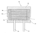
- Cross-sectional explanatory drawing which shows the state which accommodated the core in the housing.
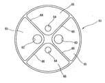
- the top view which shows the structure of the inner bottom face of a body.
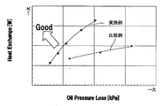
- the characteristic view which showed the heat exchange amount and the pressure loss by contrasting an Example and a comparative example.
- FIG. 1 is a perspective view showing a core 1 of a heat exchanger according to the present invention
- FIG. 2 is an exploded perspective view showing a combination of a plurality of types of plates constituting the core 1.
- the heat exchanger of this embodiment is an oil cooler suitable for cooling oil such as lubricating oil of an automobile engine or hydraulic oil of an automatic transmission, for example, as oil as a first fluid and as a second fluid. Heat exchange with the cooling water (water).
- the core 1 of the example has a cylindrical shape as a whole, and in particular, a flat cylindrical shape whose axial dimension is smaller than the diameter.
- the core 1 is formed in a columnar shape by laminating a large number of thin plates each having a circular outer shape in the axial direction. As shown in FIG. Three types of plates, a plate 11, a second plate 12, and a heat transfer plate 13, are included. Then, the first plate 11 and the second plate 12 are alternately stacked with the heat transfer plate 13 interposed therebetween.
- each of the plates 11, 12, and 13 is a flat circular plate along a plane.
- These three plates 11, 12, 13 may be of different materials or of different plate thicknesses, but in an embodiment, these three types of plates 11, 12, 13 13 are formed from the same base material having the same plate thickness.
- each is comprised from the metal plate like stainless steel.
- the plate thickness is preferably 0.1 mm to 0.5 mm, and in one embodiment, 0.2 mm.
- the first plate 11 and the second plate 12 have exactly the same shape. In other words, both are the same plate, and only the direction of combination in stacking is different.
- the diameter of the core 1, that is, the diameters of the plates 11, 12, and 13 is not particularly limited, but can be configured to be, for example, about 50 mm to 100 mm, and is 75 mm in one embodiment.
- the first plate 11 is a plate for forming an oil flow path in the core 1 and has a large first opening 21 at the center.
- a pair of relatively small port openings 22 and 23 are positioned on both sides of the first opening 21.
- the first plate 11 in order to secure a heat exchange area (that is, a flow path area) as large as possible, the first plate 11 has a so-called skeleton structure in which a large portion is opened leaving a thin width rib in a necessary portion. ing.
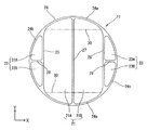
- the first plate 11 when described as a skeleton structure, includes a circular rib 24 along the outer circumference circle, a pair of chord direction ribs 25 and 26 along a chord of a circle extending in the Y direction, and the first opening 21.
- the first opening 21 is formed by a pair of chordal ribs 25, 26 that form a straight line parallel to each other and a pair of arcuate portions 24 a of a circular rib 24 that connects the chordal ribs 25, 26.
- the whole of is divided.
- the first opening 21 is further divided into a pair of first openings 21A and 21B by a linear central rib 27 along the diameter line.
- the entire port openings 22 and 23 are defined by the respective chordal ribs 25 and 26 and the arcuate portion 24b of the circular rib 24 on the outside thereof.
- the port openings 22 and 23 are further divided into a pair of port openings 22A, 22B, 23A, and 23B by the port dividing ribs 28 and 29, respectively.
- the first plate 11 including the string direction ribs 25 and 26, the center rib 27, and the port division ribs 28 and 29 has a line-symmetric shape in each of the X direction and the Y direction, and also has a rotationally symmetric shape.
- the central rib 27 and the port division ribs 28 and 29 are not necessarily essential.
- the first opening 21 has a central rectangular portion that occupies most of the region as a heat exchange region, and portions on both sides (outside) in the Y direction serve as inlet or outlet port regions.
- the boundary between these two regions is indicated by a virtual line 30. In the illustrated example, there is no physical boundary between the two areas.
- the second plate 12 is a plate for forming a cooling water flow path in the core 1.
- the second plate 12 is exactly the same plate as the first plate 11 as a single component, and when stacked as the core 1, the orientation (the orientation in the rotational direction) of the first plate 11 is 90 °. Although they are stacked differently, in order to facilitate understanding, hereinafter, each part will be described with reference numerals different from those of the first plate 11.
- the second plate 12 has a large second opening 31 at the center, and a pair of relatively small port openings 32 and 33 are formed on both sides of the second opening 31. Open. That is, the second plate 12 has two parallel flow paths through the circular rib 34 along the outer circumferential circle, the pair of chordal ribs 35 and 36 along the chord of the circle extending in the X direction, and the second opening 31.
- a port section extending in the Y direction so as to connect the central rib 37 along the diameter line of the circle extending in the X direction so as to be divided into the circular ribs 34 adjacent to the center of each chord direction rib 35, 36. Ribs 38 and 39.
- the entire second opening 31 is formed by a pair of chordal ribs 35, 36 that are parallel to each other and a pair of arcuate portions 34a of a circular rib 34 that connects the chordal ribs 35, 36. It is partitioned.
- the second opening 31 is further divided into a pair of second openings 31A and 31B by a linear central rib 37 along the diameter line.
- the entire port openings 32 and 33 are defined by the respective chordal ribs 35 and 36 and the arcuate portion 34b of the circular rib 34 on the outside thereof.
- These port openings 32 and 33 are further divided into a pair of port openings 32A, 32B, 33A, and 33B by port partition ribs 38 and 39, respectively.
- center rib 37 and the port division ribs 38 and 39 in the 2nd plate 12 are not necessarily essential.
- the second opening 31 has a central rectangular portion that occupies most of the region as a heat exchange region, and portions on both sides (outside) in the X direction are inlet or outlet ports. It becomes an area.
- the boundary between these two regions is indicated by a virtual line 40. In the illustrated example, there is no physical boundary between the two regions.
- the heat transfer plate 13 overlaps with the first plate 11 and the second plate 12 to define a boundary surface in the laminating direction of each oil flow channel and the cooling water flow channel (the axial direction of the cylinder). It constitutes a heat transfer wall between.
- the heat transfer plate 13 includes a pair of port openings 41, 42 corresponding to the port openings 22, 23 of the first plate 11 when the plates 11, 12, 13 are stacked. And a pair of port openings 43 and 44 respectively corresponding to the port openings 32 and 33 of the second plate 12.
- the heat transfer plate 13 includes a circular rib 45 along the outer circumferential circle, a central heat transfer wall portion 46 that forms a square along each side of the circular chord along the X direction or the Y direction, and the heat transfer.
- Port section ribs 47 and 48 extending in the X direction and port section ribs 49 and 50 extending in the Y direction so as to connect the center of the four sides of the wall portion 46 and the adjacent circular rib 45 are provided.
- the pair of port openings 41 and 42 are further divided into two pairs of port openings 41A, 41B, 42A and 42B by the port dividing ribs 47 and 48, respectively.
- the pair of port openings 43 and 44 are further divided into two pairs of port openings 43A, 43B, 44A, and 44B by the port partition ribs 49 and 50, respectively.
- the port openings 41, 42, 43, 44 (41A, 41B, 42A, 42B, 43A, 43B, 44A, 44B) of the heat transfer plate 13 are the port openings 22, 23 (22A, 22B, 23A, 23B) and the port openings 32, 33 (32A, 32B, 33A, 33B) of the second plate 12, respectively, are in positions that match each other when overlapped.
- the four port openings 41, 42, 43, and 44 are opened in the same shape every 90 °.
- the first plate 11, the second plate 12, and the heat transfer plate 13 are stacked so that the first plate 11 and the second plate 12 are alternately positioned with the heat transfer plate 13 interposed therebetween.
- the heat transfer plate 13, the second plate 12, the heat transfer plate 13, the first plate 11, the heat transfer plate 13, the second plate 12, the heat transfer plate 13. Are laminated.
- a heat transfer plate 13 is located on the lowermost surface, and the second plate from the bottom adjacent to this is the second plate 12.
- the heat transfer plate 13 is located on the uppermost surface, and the second plate from the top adjacent to this is the second plate 12.
- 45 first plates 11 and 46 second plates 12 are alternately stacked with the heat transfer plate 13 interposed therebetween.
- heat transfer plate 13, second plate 12, heat transfer plate 13, first plate 11 it has a 45-stage configuration.
- the number of layers is not limited to 45, and a laminated structure with other numbers such as 30 and 60 is possible.
- FIG. 6 schematically shows a cross section taken along line AA of FIG.
- the oil flow path 51 and the cooling water flow path 52 are alternately configured by alternately stacking the first plate 11 and the second plate 12 with the heat transfer plate 13 interposed therebetween.
- the oil flow path 51 is formed between the upper and lower heat transfer plates 13 by the first opening 21 of the first plate 11. Therefore, the flow path has a narrow thickness corresponding to the thickness of the first plate 11.
- the cooling water passage 52 is formed between the upper and lower two heat transfer plates 13 by the second opening 31 of the second plate 12. Accordingly, the flow path is narrow with a thickness corresponding to the thickness of the second plate 12.
- both the oil passage 51 and the cooling water passage 52 are substantially 0.2 mm thick.
- these oil flow paths 51 and the cooling water flow paths 52 are adjacent to each other in the stacking direction via the heat transfer plate 13 between them, whereby heat exchange between the oil and the cooling water is performed. .
- the number of plate stages is 45
- these oil flow path 51 and the cooling water flow path 52 are not equipped with the uneven
- the wall surface of the heat transfer plate 13 (that is, the surface of the heat transfer wall portion 46) forming the oil channel 51 and the cooling water channel 52 is as smooth and smooth as possible.
- the oil flow path 51 has the port regions at both ends, which are part of the first opening 21, the port openings 43 and 44 of the adjacent heat transfer plate 13 and the port opening of the second plate 12.
- the oil flows in and out through these port openings 43, 44, 32, and 33.
- the port opening 43 of the heat transfer plate 13 and the port opening 32 of the second plate 12 serve as an oil inlet, and one end of the first opening 21 that overlaps with these serves as an inlet port region.
- the port opening 44 of the heat transfer plate 13 and the port opening 33 of the second plate 12 serve as an oil outlet, and the other end of the first opening 21 that overlaps with the port opening serves as an outlet port region.
- the oil channel is divided into two parallel channels (first openings 21A and 21B) by the central rib 27 (see FIG. 3), and these two channels are oriented in the same direction. Oil flows in parallel to.
- the cooling water flow path 52 and the port regions at both ends, which are part of the second opening 31, have the port openings 41, 42 of the adjacent heat transfer plate 13 and the first plate 11.
- the port openings 22 and 23 are overlapped with each other, and cooling water flows in and out through the port openings 41, 42, 22 and 23.
- the port opening 41 of the heat transfer plate 13 and the port opening 22 of the first plate 11 serve as cooling water inlets, and one end of the second opening 31 that overlaps with these serves as an inlet port region.
- the port opening 42 of the heat transfer plate 13 and the port opening 23 of the first plate 11 serve as a cooling water outlet, and the other end of the second opening 31 that overlaps with these serves as an outlet port region.
- the cooling water flow path is divided into two parallel flow paths (second openings 31A and 31B) by the central rib 37 (see FIG. 4), and these two flow paths are oriented in the same direction. Cooling water flows parallel to
- the port opening 43 serving as the oil inlet and the port opening 32 serving as the oil inlet are the inlet ports of the oil passage 51 for all the 45 oil passages 51.
- the core 1 is aligned with the region in the stacking direction.
- the oil inlet port 55 is formed in a continuous passage shape along the stacking direction of the cores 1 (see FIG. 1).
- the port opening 44 and the port opening 33 serving as the oil outlet are aligned in the stacking direction of the core 1 together with the outlet port area of the oil flow path 51. Thereby, an oil outlet port 56 continuous along the stacking direction of the cores 1 is formed.
- the oil inlet port 55 is divided into a pair of oil inlet ports 55A and 55B by the port dividing rib 38.
- the oil outlet port 56 is divided into two oil outlet ports 56 ⁇ / b> A and 56 ⁇ / b> B by the port partition rib 39.
- the port opening 41 and the port opening 22 that serve as cooling water inlets are aligned with the inlet port region of the cooling water channel 52 in the stacking direction of the core 1.
- a continuous cooling water inlet port 57 is formed along the stacking direction of the cores 1.
- the port opening 42 and the port opening 23 serving as the cooling water outlet are aligned in the stacking direction of the core 1 together with the outlet port region of the cooling water flow path 52, and thereby, along the stacking direction of the core 1.
- a continuous cooling water outlet port 58 is formed.
- the cooling water inlet port 57 and the cooling water outlet port 58 are equally divided into a pair of cooling water inlet ports 57A and 57B and cooling water outlet ports 58A and 58B, respectively.
- the plates 11 to 13 constituting the core 1 are densely laminated in the laminating direction, and the respective contact surfaces are joined to each other.
- the core 1 in which the plates 11 to 13 are laminated is heated to below the melting point of the base material while being pressed in the laminating direction, and is joined using diffusion of atoms between the joining surfaces. As a result, the entire core 1 is integrally joined.
- the surfaces of the plates 11 to 13 may be bonded to each other by means other than diffusion bonding.
- the core 1 has very high rigidity and strength.
- the individual plates 11 to 13 can be formed to be sufficiently thin without being restricted in terms of rigidity and strength required for the final core 1, and accordingly, heat exchange can be performed.
- the oil flow path 51 and the cooling water flow path 52 to be performed can have a very narrow thickness corresponding to the plate thickness of the plates 11 and 12 (for example, 0.2 mm).
- the core 1 configured as described above is connected to the oil inlet port 55 and the oil outlet port 56 with oil pipes serving as the inlet side oil passage and the outlet side oil passage, respectively, and the cooling water inlet port 57 and the cooling water outlet port 58 are connected.
- a heat exchanger that is, an oil cooler is configured.
- the core 1 is housed inside, and an oil pipe 63 and a cooling water pipe 64 provided in the body 61 communicate with the ports 55 to 58 of the core 1.
- the cylindrical wall 61a of the body 61 has a thread on the outer peripheral surface, and the cylindrical wall 62a of the cap 62 has a thread on the inner peripheral surface, and these are screwed together.
- An appropriate sealing material for example, a silicone resin-based sealing material 68 is filled in the inside of the housing 60, that is, the gap between the inner peripheral surface of the cylindrical wall portions 61 a and 62 a and the outer peripheral surface of the core 1. Note that a small hole may be provided in the cap 62 so that excess sealing material overflows when the cap 62 is tightened by screwing. Further, in addition to filling the internal sealing material, the sealing material may be applied so as to cover the screwed surfaces of the cylindrical wall portions 61 a and 62 a on the outer peripheral surface of the housing 60.
- each guide recesses 65 On the inner bottom surface of the body 61 with which one end surface of the core 1 is in contact, four fan-shaped guide recesses 65 are formed every 90 °, as shown in a simplified manner in FIG. These guide recesses 65 are partitioned from each other by a partition wall 66 provided at an appropriate height on the inner bottom surface of the body 61.
- the partition wall 66 has a top formed along one plane, and is joined to the end surface of the core 1 via an appropriate adhesive when the core 1 is accommodated in the housing 60.
- An oil pipe 63 and a cooling water pipe 64 are connected to the guide recesses 65 from the outside of the body 61, respectively.
- a pair of oil pipes 63 having a relatively large diameter are connected to a pair of guide recesses 65 separated by 180 °, and a pair of cooling water pipes 64 having a relatively small diameter are left as a pair of remaining guide recesses 65. It is connected to the.
- each of the four guide recesses 65 is one of an oil inlet port 55, an oil outlet port 56, a cooling water inlet port 57, and a cooling water outlet port 58 of the core 1.
- one of the pair of oil pipes 63 is connected to the oil inlet port 55 and the other is connected to the oil outlet port 56.
- one of the pair of cooling water pipes 64 is connected to the cooling water inlet port 57 and the other is connected to the cooling water outlet port 58.
- the high-temperature oil pressure-fed to the oil inlet port 55 of the core 1 via the oil pipe 63 is parallel to the 45 oil flow paths 51. Flows and is discharged from the oil outlet port 56.
- the relatively low-temperature cooling water pumped to the cooling water inlet port 57 of the core 1 by the cooling water pump flows in parallel with the 46 cooling water flow paths 52 and is discharged from the cooling water outlet port 58.
- the oil flows along the Y direction, and the cooling water flows along the X direction having an angle of 90 ° with respect to the oil flow.
- both the oil flow path 51 and the cooling water flow path 52 are narrow flow paths of about 0.2 mm, for example.
- the thickness of the temperature boundary layer of oil or water is, for example, about 0.1 mm, and in the flow path having a sufficiently small thickness as in the above embodiment, most of the fluid flow is occupied by the temperature boundary layer.
- the proportion of the central mainstream that is not affected by heat between the two heat transfer surfaces is very small (ideally 0) and depends on the destruction of the temperature boundary layer by some kind of fins or stirring. High heat transfer efficiency can be obtained.
- the oil flow channel 51 and the cooling water flow channel 52 are narrow flow channels having a small thickness, but there are no inner fins, uneven portions, or the like in these flow channels, and two transmissions composed of smooth surfaces. It tends to flow as a laminar flow (of course, there is a velocity gradient due to viscosity) between the heat plates 13 (heat transfer walls 46). Therefore, even if the thickness of the flow path is small, the increase in pressure loss is relatively small.
- the individual plates 11 to 13 are thin, the oil flow path 51 and the cooling water flow are assumed when the height dimension in the laminating direction is made equal compared to a conventional plate laminating type oil cooler using a cup plate.
- the number of steps in the stacking direction of the paths 52 is much larger. By setting the number of stages, the pressure loss can be reduced as a result.
- the heat exchange amount and pressure loss in the oil cooler using the core 1 of the embodiment described above were measured under the conditions of an oil temperature of 120 ° C. and an oil flow rate of 7.5 L / min, the heat exchange amount was 7.
- the pressure loss on the oil side was 4 kPa and 41 kPa.
- the heat exchange amount was 7.1 kW, and the oil-side pressure loss was 120 kPa. That is, in the said Example, compared with the conventional oil cooler, a pressure loss becomes small and the heat exchange amount and the pressure loss are compatible on a high dimension.
- the plate area in plan view is substantially equal in one embodiment and the comparative example.
- the height in the stacking direction of the core 1 of one embodiment was about 36 mm
- the height in the stacking direction of the conventional plate stack type oil cooler was about 55 mm. That is, the core 1 of one embodiment is advantageous in terms of height.
- FIG. 9 is a characteristic diagram showing the correlation between the heat exchange amount and the pressure loss when the oil flow rate is changed in comparison between the above example and the above comparative example.
- the heat exchange amount increases, but at the same time, the pressure loss also increases.
- the characteristics of the example are located on the upper left side of the figure as a whole than the characteristics of the comparative example. If the pressure loss is the same, the embodiment can obtain a larger heat exchange amount than the comparative example, or if the heat exchange amount is the same, the embodiment has a lower pressure loss than the comparative example. means.
- FIG. 10 shows a modified example of the first plate 11 or the second plate 12.
- the first plate 11 constituting the oil passage 51 is described, but the second plate 12 constituting the cooling water passage 52 may be used.
- the first plate 11 of this embodiment includes a first opening 21 including a heat exchange area and an inlet or outlet port area, and divides the first opening 21 into two openings 21A and 21B.
- the central rib 27 extending in the Y direction is provided, and the labyrinth forming rib 71 for meandering the flow path in the plane of the first plate 11 is provided in the region of the first opening 21. Yes.
- three labyrinth forming ribs 71 extending in the X direction from the chordal ribs 25 and 26 are provided, and 2 extending from the central rib 27 in the X direction.
- Two labyrinth forming ribs 71 are provided. These labyrinth forming ribs 71 are alternately arranged to form a meandering flow path that makes a U-turn a plurality of times.
- the two labyrinth forming ribs 73 connected to both ends of the chordal ribs 25 and 26 are along the boundary between the heat exchange region in the first opening 21 and the port region of the inlet or outlet.
- the flow path length from the inlet port to the outlet port of the oil flow path 51 or the cooling water flow path 52 is substantially increased. Can do. Therefore, an oil cooler having desired characteristics can be easily obtained by appropriately using the plates 11 and 12 having such a configuration.
- FIG. 11 shows a further modification of the first plate 11 or the second plate 12.
- the first plate 11 constituting the oil passage 51 is described, but the second plate 12 constituting the cooling water passage 52 may be used.
- the first plate 11 of this embodiment does not include the central rib 27 in the first opening 21, and the entire region of the first opening 21 is a single oil flow path 51.
- a total of three labyrinth formation ribs 71 extended from the chord direction ribs 25 and 26 to the X direction were made. I have.
- the port openings 22 and 23 are each provided as one opening without providing the port partitioning ribs 28 and 29.
- each port opening can be formed as one opening that does not include the port division rib.
- the core 1 of the embodiment shown in FIG. 1 is provided with a central rib and a port partitioning rib so that each stage of the oil flow path 51 and the cooling water flow path 52 are divided into two flow paths, respectively. Eight port openings are provided. Therefore, various aspects and various combinations are possible with respect to the flow of oil through the core 1 and the flow of cooling water.
- FIG. 12 shows some examples of oil flow and cooling water flow. Here, the flow of oil is indicated by an arrow O, and the flow of cooling water is indicated by an arrow W.
- (A) of FIG. 12 is configured so that oil flows parallel to the two oil flow paths 51A and 51B and cooling water flows parallel to the two cooling water flow paths 52A and 52B, as described above. It is. Oil and cooling water flow so as to cross each other at an angle of 90 °.
- (B) is configured such that oil flows in parallel to the two oil flow paths 51A and 51B, while cooling water flows in opposite directions to the two cooling water flow paths 52A and 52B.
- one of the cooling water ports 57A and 57B divided by the port section rib is an inlet port and the other is an outlet port.
- one of the cooling water outlet ports 58A and 58B is an inlet port and the other is an outlet port. It becomes.
- cooling water flows in parallel to the two cooling water flow paths 52A and 52B, while the oils are opposite to each other in the two oil flow paths 51A and 51B. It is configured to flow in the direction.
- (D) is a combination of the configuration of the cooling water flow path 52 in the example of (b) and the configuration of the oil flow path 51 in the example of (c), and the oil flows as an opposing flow to the two oil flow paths 51A and 51B. Flows in opposite directions to each other, and the cooling water flows in opposite directions to the two cooling water flow paths 52A and 52B as opposite flows.
- FIG. 13 shows a second embodiment of the present invention.
- the oil and cooling water adjacent to each other across the heat transfer wall flow as an opposing flow, and the rectangular first plate 11 and second plate 12 are connected to the heat transfer plate 13. It is the structure laminated
- the first plate 11 has port openings 22 and 23 at one end on the right side in the longitudinal direction, and the first opening 21 at the remaining portion.
- the first opening 21 is divided into two regions by the central rib 27, and one end portion (for port) of the central rib 27 is formed so that these two regions constitute one flow path that is continuous in a U shape.
- the ends near the openings 22 and 23 are cut out.
- the central rib 27 is a short one having a free end at the tip.
- the second plate 12 has port openings 32 and 33 at one end on the left side in the longitudinal direction and the second opening 31 at the remaining portion.
- the second opening 31 is divided into two regions by the central rib 37.
- One end of the central rib 37 (for the port) so that these two regions constitute one flow path that is continuous in a U-shape.
- the end portions near the openings 32 and 33 are cut out.
- the central rib 37 is a short one having a free end at the tip.
- the heat transfer plate 13 has four port openings 41, 42, 43, 44 that overlap the port openings 22, 23 of the first plate 11 and the port openings 32, 33 of the second plate 12 at the four corners. I have.
- the port opening 43 serves as an oil inlet
- the port opening 44 serves as an oil outlet.
- the oil flows in an U-turn as indicated by an arrow O in the oil flow path 51 formed by the first plate 11.
- the port opening 41 serves as a cooling water inlet
- the port opening 42 serves as a cooling water outlet
- the cooling water U-turns as indicated by an arrow W in the cooling water flow path 52 formed by the second plate 12.
- FIG. 14 shows a third embodiment of the present invention.
- the first opening 21 of the first plate 11 forming the oil flow path 51 is divided into two first openings 21A and 21B by a central rib 27 extending in the X direction.
- a second central rib 72 projecting from the circular rib 24 toward the inner peripheral side along the Y direction and a plurality of labyrinth forming ribs 71 are provided. Therefore, one of the port openings 43A and 43B of the heat transfer plate 13 is an oil inlet, the other is an oil outlet, and similarly, one of the port openings 44A and 44B is an oil inlet and the other is an oil outlet.
- the second plate 12 is a plate in which the same shape as the first plate 11 is arranged with the direction changed by 90 °. That is, the second opening 31 of the second plate 12 forming the cooling water flow path 52 is divided into two second openings 31A and 31B by the central rib 37 extending in the Y direction. Accordingly, one of the port openings 41A and 41B of the heat transfer plate 13 is a cooling water inlet and the other is a cooling water outlet. Similarly, one of the port openings 42A and 42B is a cooling water inlet and the other is a cooling water. As an outlet, for example, as indicated by an arrow W, cooling water flows in each region.
- FIG. 15 is a modification of the third embodiment, and the configuration itself of the first plate 11, the second plate 12, and the heat transfer plate 13 is the same as the example of FIG.
- the aspect of the flow of oil (arrow O) and the flow of cooling water (arrow W) is changed by partially changing the relationship between the inlet and outlet of oil and cooling water.
- the flow of oil that flows through the oil flow path 51 and the flow of cooling water that flows through the cooling water flow path 52 become counterflows that generally go in opposite directions.
- FIG. 16 shows a fourth embodiment of the present invention.
- the first opening 21 of the first plate 11 forming the oil flow path 51 is divided into two first openings 21A and 21B by a central rib 27 extending in the X direction.
- a second central rib 72 projecting from the circular rib 24 toward the inner peripheral side along the Y direction and a plurality of labyrinth forming ribs 71 are provided.
- the arrangement of the labyrinth forming ribs 71 is different from that of the first plate 11 of the third embodiment.
- one of the port openings 43A and 43B of the heat transfer plate 13 is an oil inlet
- the other is an oil outlet
- one of the port openings 44A and 44B is an oil inlet.
- the second plate 12 is a plate in which the same shape as the first plate 11 is arranged with the direction changed by 90 °. That is, the second opening 31 of the second plate 12 forming the cooling water flow path 52 is divided into two second openings 31A and 31B by the central rib 37 extending in the Y direction. Accordingly, one of the port openings 41A and 41B of the heat transfer plate 13 is a cooling water inlet and the other is a cooling water outlet. Similarly, one of the port openings 42A and 42B is a cooling water inlet and the other is a cooling water. As an outlet, for example, as indicated by an arrow W, cooling water flows in each region.
- the flow of oil flowing through the oil flow path 51 and the flow of cooling water flowing through the cooling water flow path 52 are substantially along the same direction.
- FIG. 17 is a modification of the fourth embodiment, and the configuration itself of the first plate 11, the second plate 12, and the heat transfer plate 13 is the same as the example of FIG.
- the aspect of the flow of oil (arrow O) and the flow of cooling water (arrow W) is changed by partially changing the relationship between the inlet and outlet of oil and cooling water.
- the flow of oil that flows through the oil flow path 51 and the flow of cooling water that flows through the cooling water flow path 52 become counterflows that generally go in opposite directions.
- Each of the plates 11 to 13 including the heat transfer plate 13 is made of stainless steel in the above-described embodiment.
- these plates 11 to 13 are made relatively heat conductive such as titanium or a resin composite material. It can also be formed from a low rate material. This is because, as described above, the flow paths 51 and 52 are made to have small thicknesses, so that the heat exchange efficiency between the wall surface and the fluid is high, and the heat transfer plate 13 is thin, so This is because the influence of low thermal conductivity is reduced.
- each of the plates 11 to 13 can be formed using a thin plate-like material in which a carbon fiber woven fabric is impregnated with a resin material such as an epoxy resin as a resin composite material. In this case, it is possible to form the core 1 by laminating these plates 11 to 13 and pressurizing and heating them so that the plates 11 to 13 are joined together.
Landscapes
- Engineering & Computer Science (AREA)
- Physics & Mathematics (AREA)
- Thermal Sciences (AREA)
- Mechanical Engineering (AREA)
- General Engineering & Computer Science (AREA)
- Heat-Exchange Devices With Radiators And Conduit Assemblies (AREA)
Abstract
オイルクーラのコア(1)は、それぞれ薄い金属プレー卜からなる複数の第1プレ—卜(11)と第2プレー卜(12)と伝熱プレー卜(13)とを含む。第1プレー卜(11)と第2プレート(12)とが伝熱プレート(13)を挟んで交互に積層されている。第1プレート(11)は、オイル流路(51)を形成するための第1開口部(21)と、ポ一卜用開口部(22,23)と、を有する。第2プレート(11)は、冷却水流路(52)を形成するための第2開口部(31)と、ポ一卜用開口部(32,33)と、を有する。オイル流路(51)と冷却水流路(52)とが伝熱プレ—卜(13)を挟んで隣接する。流路(51,52)の厚みを、温度境界層の厚みに近づけることで、高い効率で熱交換がなされる。
Description
この発明は、オイルクーラ等に好適な熱交換器に関する。
特許文献1は、オイルと水(冷却水)との間で熱交換を行うオイルクーラとして、典型的なプレート積層型のオイルクーラを開示している。この形式のオイルクーラは、それぞれ周縁が斜めに立ち上がった第1のカッププレートと第2のカッププレートとを交互に積層し、これらのプレートの間に、オイル流路と冷却水流路とを交互に形成した構成となっている。そして、特許文献1が開示しているように、熱交換効率を高めるために、オイル流路内にインナーフィン(フィンプレートとも呼ばれる)が挟み込まれているのが一般的である。また冷却水流路内には、一方のカッププレートに形成した多数の突起が配置されている。
熱交換の原理として、例えば、2枚のプレートに挟まれて構成される流路をある流体が流れるときに、流体とプレートとが異なる温度である場合の両者間の伝熱を考えると、流体の温度は、プレート表面に近いいわゆる温度境界層のみで変化し、プレートから離れたいわゆる主流の中ではプレート温度の影響を受けない。
オイルや水等の液体の流れでは、温度境界層の厚みはかなり小さく、1mm未満のオーダ、例えば0.1mm程度のものとなりうる。このような温度境界層の厚さのオーダに比較して、従来のプレート積層型の熱交換器におけるプレート間の流路(オイル流路および冷却水流路)の厚みは、数mm程度のオーダであり、遙かに大きい。
従って、従来のプレート積層型の熱交換器にあっては、仮にインナーフィンや突起が流路内に存在しないと、流体の流れの大部分が主流として熱交換に寄与しないまま流れ出てしまうことになり、本質的に熱交換効率が低い。
そのため、従来のプレート積層型の熱交換器では、インナーフィン等によって流れの中の温度境界層を攪拌ないし破壊し、熱交換効率の向上を図っている。しかしながら、このようなコンセプトでは、必然的に流体の流れの乱れを伴い、熱交換量の向上代に比較して圧力損失の増加代が大きい。
この発明の目的は、新たなコンセプトに基づく新規な構成の熱交換器を提供し、熱交換量と圧力損失とを高い次元で両立させることにある。
この発明の熱交換器は、
それぞれ液体からなる第1の流体と第2の流体との間で熱交換を行う熱交換器であって、
第1の流体が導かれる第1開口部を有する複数の第1プレートと第2の流体が導かれる第2開口部を有する複数の第2プレートとを含み、かつ各々の第1プレートと各々の第2プレートとがそれぞれ伝熱プレートを挟んで交互に積層されており、
上記第1プレートの板厚に相当する厚みの第1の流体用の第1流路が上記第1開口部によって構成されており、上記第2プレートの板厚に相当する厚みの第2の流体用の第2流路が上記第2開口部によって構成されており、これら2つの流路が伝熱プレートを介して積層方向に隣接している。
それぞれ液体からなる第1の流体と第2の流体との間で熱交換を行う熱交換器であって、
第1の流体が導かれる第1開口部を有する複数の第1プレートと第2の流体が導かれる第2開口部を有する複数の第2プレートとを含み、かつ各々の第1プレートと各々の第2プレートとがそれぞれ伝熱プレートを挟んで交互に積層されており、
上記第1プレートの板厚に相当する厚みの第1の流体用の第1流路が上記第1開口部によって構成されており、上記第2プレートの板厚に相当する厚みの第2の流体用の第2流路が上記第2開口部によって構成されており、これら2つの流路が伝熱プレートを介して積層方向に隣接している。
この熱交換器にあっては、第1流路および第2流路のいずれも、第1プレートないし第2プレートの板厚に相当する厚みの狭小な流路となる。第1プレート、第2プレートおよび伝熱プレートは、密に積層された構成であるので、剛性や強度からの制約が少ないため、第1プレートないし第2プレートの板厚を十分に小さくすることが可能であり、第1流路および第2流路の厚みが十分に小さなものとなる。従って、各々の流路を流れる流れの中で温度境界層が占める割合が大きくなり、理想的には流れの大部分を温度境界層が占めるようにすることが可能である。これにより、熱交換効率が向上する。
一方、この熱交換器では、隣接する2つの伝熱プレートによって形成される流路(第1流路ないし第2流路)の中を流体(第1の流体ないし第2の流体)が層流となって流れる。換言すれば、インナーフィン等による積極的な攪拌や乱流形成が不要である。そのため、流路の厚みを小さくしても、圧力損失の増加は比較的に小さい。
従って、熱交換量と圧力損失とを高い次元で両立させることができる。
以下、この発明の一実施例を図面に基づいて詳細に説明する。
図1は、この発明に係る熱交換器のコア1を示す斜視図であり、図2は、このコア1を構成する複数種類のプレートの組み合わせを示した分解斜視図である。この実施例の熱交換器は、例えば自動車のエンジンの潤滑油や自動変速機の作動油等のオイルの冷却に好適なオイルクーラであって、第1の流体としてのオイルと第2の流体としての冷却水(水)との間で熱交換を行うものである。
実施例のコア1は、全体として円柱状、特に、軸方向の寸法が直径よりも小さな偏平な円柱状をなしている。このコア1は、外形がそれぞれ円形をなす薄いプレートを軸方向に多数積層することで円柱状に構成されているものであり、構成要素となるプレートとしては、図2に示すように、第1プレート11と、第2プレート12と、伝熱プレート13と、の3つの種類のプレートを含んでいる。そして、第1プレート11と第2プレート12とが伝熱プレート13を挟んで交互に積層されている。一実施例においては、各プレート11,12,13は、いずれも平面に沿った平坦な円形のプレートである。
これらの3つのプレート11,12,13は、それぞれ異なる材質であってもよく、また異なる板厚のものであってもよいが、—実施例では、これらの3つの種類のプレート11,12,13が、同じ板厚を有する同じ母材から形成されている。例えば、ステンレス鋼のような金属板からそれぞれ構成されている。板厚としては、0.1mm~0.5mmであることが望ましく、一実施例では、0.2mmである。また、図2の実施例では、第1プレート11と第2プレート12は、全く同一の形状を有している。換言すれば両者は同一のプレートであって、積層時に組み合わせる方向のみが異なっている。なお、コア1の直径つまりプレート11,12,13の直径は、特に限定されるものではないが、例えば50mm~100mm程度に構成することができ、一実施例では、75mmである。
図3、図4、図5は、それぞれ、第1プレート11、第2プレート12、伝熱プレート13、の詳細を示している。これらの図には、説明の便宜のためにそれぞれX,Y方向を矢印とともに付した。これらのX,Y方向が整列した形でもってこれらのプレート11,12,13が積層される。
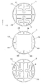
第1プレート11は、コア1内にオイル流路を形成するためのプレートであり、中央部に大きな第1開口部21を有する。また第1開口部21の両側に、相対的に小さな一対のポート用開口部22,23が位置している。ここで図示例では、熱交換面積(つまり流路面積)をできるだけ大きく確保するために、第1プレート11は、必要な部分に細い幅のリブを残して大部分が開口したいわゆるスケルトン構造をなしている。従って、スケルトン構造として記述すると、第1プレート11は、外周円に沿った円形リブ24と、Y方向に延びる円の弦に沿った一対の弦方向リブ25,26と、第1開口部21を2つの平行な流路に区分するようにY方向に延びた円の直径線に沿った中央リブ27と、各弦方向リブ25,26の中央と隣接する円形リブ24とを接続するようにX方向に延びたポート区分リブ28,29と、を備えている。
図3に示すように、互いに平行な直線状をなす一対の弦方向リブ25,26とこれらの弦方向リブ25,26を接続する円形リブ24の一対の弧状部分24aとによって第1開口部21の全体が区画されている。この第1開口部21は、直径線に沿った直線状の中央リブ27によってさらに一対の第1開口部21A,21Bに2分されている。また各々の弦方向リブ25,26とその外側の円形リブ24の弧状部分24bとによってポート用開口部22,23の全体が区画されている。これらのポート用開口部22,23は、ポート区分リブ28,29によってさらにそれぞれ一対のポート用開口部22A,22B,23A,23Bに2分されている。
弦方向リブ25,26、中央リブ27、ポート区分リブ28,29を含む第1プレート11は、X方向およびY方向の各々について線対称の形状であり、また回転対称形状でもある。
なお、本発明において、中央リブ27およびポート区分リブ28,29は必ずしも必須のものではない。
第1開口部21は、その領域の大部分を占める中央の矩形部分が熱交換領域となり、Y方向での両側(外側)となる部分が入口ないし出口のポート領域となる。図3には、これら2つの領域の境界を仮想線30でもって示してある。なお、図示例では、2つの領域の間に物理的な境界はない。
第2プレート12は、コア1内に冷却水流路を形成するためのプレートである。前述したように、第2プレート12は部品単体としては第1プレート11と全く同一のプレートであり、コア1として積層する際に、第1プレート11とは向き(回転方向の姿勢)が90°異なるようにして積層されるものであるが、理解を容易にするために、以下では、第1プレート11とは異なる符号を付して各部を説明する。
第2プレート12は、図4に示すように、中央部に大きな第2開口部31を有し、この第2開口部31の両側に、相対的に小さな一対のポート用開口部32,33が開口する。すなわち、第2プレート12は、外周円に沿った円形リブ34と、X方向に延びる円の弦に沿った一対の弦方向リブ35,36と、第2開口部31を2つの平行な流路に区分するようにX方向に延びた円の直径線に沿った中央リブ37と、各弦方向リブ35,36の中央と隣接する円形リブ34とを接続するようにY方向に延びたポート区分リブ38,39と、を備えている。
図示するように、互いに平行な直線状をなす一対の弦方向リブ35,36と両弦方向リブ35,36を接続する円形リブ34の一対の弧状部分34aとによって第2開口部31の全体が区画されている。この第2開口部31は、直径線に沿った直線状の中央リブ37によってさらに一対の第2開口部31A,31Bに2分されている。また各々の弦方向リブ35,36とその外側の円形リブ34の弧状部分34bとによってポート用開口部32,33の全体が区画されている。これらのポート用開口部32,33は、ポート区分リブ38,39によってさらにそれぞれ一対のポート用開口部32A,32B,33A,33Bに2分されている。
なお、第2プレート12における中央リブ37およびポート区分リブ38,39も必ずしも必須のものではない。
第2開口部31は、第1開口部21と同様に、その領域の大部分を占める中央の矩形部分が熱交換領域となり、X方向での両側(外側)となる部分が入口ないし出口のポート領域となる。図4には、これら2つの領域の境界を仮想線40でもって示してある。図示例では、2つの領域の間に物理的な境界はない。
伝熱プレート13は、第1プレート11および第2プレート12と重なることで各々のオイル流路および冷却水流路の積層方向(円柱の軸方向)の境界面を規定するとともに、オイルと冷却水との間の伝熱壁を構成するものである。
図5に示すように、伝熱プレート13は、各プレート11,12,13を積層したときに第1プレート11のポート用開口部22,23にそれぞれ対応する一対のポート用開口部41,42と、第2プレート12のポート用開口部32,33にそれぞれ対応する一対のポート用開口部43,44と、を有する。換言すれば、伝熱プレート13は、外周円に沿った円形リブ45と、各辺がX方向ないしY方向に沿う円の弦に沿った正方形をなす中央の伝熱壁部46と、伝熱壁部46の四辺の中央と隣接する円形リブ45とを接続するようにX方向に延びたポート区分リブ47,48およびY方向に延びたポート区分リブ49,50と、を有する。一対のポート用開口部41,42は、ポート区分リブ47,48によってさらにそれぞれ一対のポート用開口部41A,41B,42A,42Bに2分されている。同様に、一対のポート用開口部43,44は、ポート区分リブ49,50によってさらにそれぞれ一対のポート用開口部43A,43B,44A,44Bに2分されている。
伝熱プレート13のポート用開口部41,42,43,44(41A,41B,42A,42B,43A,43B,44A,44B)は、第1プレート11のポート用開口部22,23(22A,22B,23A,23B)および第2プレート12のポート用開口部32,33(32A,32B,33A,33B)とそれぞれ同一の形状をなしており、重ね合わせたときに互いに合致する位置にある。換言すれば、伝熱プレート13においては、4つのポート用開口部41,42,43,44が90°毎に同じ形状に開口している。
上記の第1プレート11、第2プレート12、伝熱プレート13は、前述したように、伝熱プレート13を間に挟んで第1プレート11と第2プレート12とが交互に位置するように積層されている。例えば図2に示すように、下から順に、伝熱プレート13、第2プレート12、伝熱プレート13、第1プレート11、伝熱プレート13、第2プレート12、伝熱プレート13・・・のように積層される。最下面には伝熱プレート13が位置し、これに隣接する下から2番目のプレートは第2プレート12である。同様に、最上面には伝熱プレート13が位置し、これに隣接する上から2番目のプレートは第2プレート12である。一実施例においては、45枚の第1プレート11と46枚の第2プレート12とが伝熱プレート13を挟んで交互に積層されている。すなわち、「伝熱プレート13、第2プレート12、伝熱プレート13、第1プレート11」の組み合わせを1段と呼ぶとすると、45段の構成となっている。本発明においては、勿論45段に限定されるものではなく、30段、60段といった他の段数の積層構造が可能である。
図6は、図5のA−A線に沿った断面を模式的に示している。上記のように第1プレート11と第2プレート12とを伝熱プレート13を挟んで交互に重ねることで、オイル流路51と冷却水流路52とが交互に構成される。オイル流路51は、第1プレート11の第1開口部21によって上下2枚の伝熱プレート13の間に形成される。従って、第1プレート11の板厚に相当する厚みの狭小な流路となる。冷却水流路52は、第2プレート12の第2開口部31によって上下2枚の伝熱プレート13の間に形成される。従って、第2プレート12の板厚に相当する厚みの狭小な流路となる。一実施例では、オイル流路51および冷却水流路52のいずれも、実質的に0.2mmの厚みの流路となる。そして、これらのオイル流路51と冷却水流路52とが両者間の伝熱プレート13を介して積層方向に隣接しており、これによって、オイルと冷却水との間での熱交換がなされる。プレートの段数を45段とした一実施例では、積層方向に、45個のオイル流路51と46個の冷却水流路52とが存在する。なお、これらのオイル流路51や冷却水流路52は、従前のインナーフィンのような付加的な熱交換フィンや乱流形成を促進するための凹凸部などを一切具備していない。オイル流路51や冷却水流路52を形成する伝熱プレート13の壁面(つまり伝熱壁部46の表面)は、可能な限り滑らかな平滑面である。
また、オイル流路51は、第1開口部21の一部である両端部のポート領域が、隣接する伝熱プレート13のポート用開口部43,44さらには第2プレート12のポート用開口部32,33に重なっており、これらのポート用開口部43,44,32,33を介してオイルが流入・流出する。一実施例においては、伝熱プレート13のポート用開口部43および第2プレート12のポート用開口部32がオイル入口となり、これらと重なる第1開口部21の一端部が入口ポート領域となる。そして、伝熱プレート13のポート用開口部44および第2プレート12のポート用開口部33がオイル出口となり、これらと重なる第1開口部21の他端部が出口ポート領域となる。なお、この実施例では、オイル流路が中央リブ27によって平行な2つの流路(第1開口部21A,21B)に2分されており(図3参照)、これら2つの流路を同じ向きに平行にオイルが流れる。
冷却水流路52についても基本的に同様であり、第2開口部31の一部である両端部のポート領域が、隣接する伝熱プレート13のポート用開口部41,42さらには第1プレート11のポート用開口部22,23に重なっており、これらのポート用開口部41,42,22,23を介して冷却水が流入・流出する。一実施例においては、伝熱プレート13のポート用開口部41および第1プレート11のポート用開口部22が冷却水入口となり、これらと重なる第2開口部31の一端部が入口ポート領域となる。そして、伝熱プレート13のポート用開口部42および第1プレート11のポート用開口部23が冷却水出口となり、これらと重なる第2開口部31の他端部が出口ポート領域となる。なお、この実施例では、冷却水流路が中央リブ37によって平行な2つの流路(第2開口部31A,31B)に2分されており(図4参照)、これら2つの流路を同じ向きに平行に冷却水が流れる。
コア1として複数のプレート11~13を積層した状態においては、45個のオイル流路51の全てについて、オイル入口となるポート用開口部43およびポート用開口部32がオイル流路51の入口ポート領域とともにコア1の積層方向に整列する。これにより、コア1の積層方向に沿って連続した通路状に、オイル入口ポート55が形成される(図1参照)。同様に、45個のオイル流路51の全てについて、オイル出口となるポート用開口部44およびポート用開口部33がオイル流路51の出口ポート領域とともにコア1の積層方向に整列しており、これにより、コア1の積層方向に沿って連続したオイル出口ポート56が形成される。なお、オイル入口ポート55は、ポート区分リブ38によって一対のオイル入口ポート55A,55Bに2分されている。オイル出口ポート56は、同様に、ポート区分リブ39によって一対のオイル出口ポート56A,56Bに2分されている。
また、同様に、46個の冷却水流路52の全てについて、冷却水入口となるポート用開口部41およびポート用開口部22が冷却水流路52の入口ポート領域とともにコア1の積層方向に整列しており、これにより、コア1の積層方向に沿って連続した冷却水入口ポート57が形成される。そして、冷却水出口となるポート用開口部42およびポート用開口部23が冷却水流路52の出口ポート領域とともにコア1の積層方向に整列しており、これにより、コア1の積層方向に沿って連続した冷却水出口ポート58が形成される。冷却水入口ポート57および冷却水出口ポート58は、やはりそれぞれ一対の冷却水入口ポート57A,57Bおよび冷却水出口ポート58A,58Bに2分されている。
ここで、コア1を構成する各プレート11~13は、積層方向に密に積層されており、かつ各々の接触面が互いに接合されている。一実施例においては、プレート11~13を積層したコア1を積層方向に加圧しつつ母材の融点以下に加熱して、接合面間での原子の拡散を利用して接合させる、いわゆる拡散接合によってコア1全体が一体に接合されている。なお、拡散接合以外の他の手段によってプレート11~13の各面を互いに接合するようにしてもよい。
このように多数の平坦なプレート11~13を密に積層して一体に接合することで、コア1の剛性および強度は非常に高いものとなる。換言すれば、個々のプレート11~13は、最終的なコア1に必要な剛性や強度の上で制約を受けることなく十分に薄肉に形成することが可能であり、これに伴い、熱交換を行うオイル流路51および冷却水流路52をプレート11,12の板厚(例えば0.2mm)に相当する厚みの非常に狭いものとすることが可能となる。
上記のように構成されたコア1は、オイル入口ポート55およびオイル出口ポート56に入口側オイル通路および出口側オイル通路となるオイル配管をそれぞれ接続し、冷却水入口ポート57および冷却水出口ポート58に入口側冷却水通路および出口側冷却水通路となる冷却水配管をそれぞれ接続することによって、熱交換器すなわちオイルクーラとして構成される。
オイルや冷却水の配管をどのようにしてコア1に接続するかは任意であるが、一実施例においては、図7に簡略化して示すように、ボディ61とキャップ62とからなるハウジング60の内部にコア1が収容されており、ボディ61に設けられたオイル配管63および冷却水配管64がコア1の各ポート55~58に連通している。ボディ61の円筒壁部61aは外周面に螺条を有し、キャップ62の円筒壁部62aは内周面に螺条を有し、これらが互いに螺合している。
ハウジング60の内部つまり円筒壁部61a,62a内周面とコア1の外周面との間の隙間には、適宜なシール材例えばシリコーン樹脂系のシール材68が充填されている。なお、キャップ62を螺合により締め付けていったときに余剰のシール材が溢れ出るように小さな孔をキャップ62に設けるようにしてもよい。また、内部のシール材の充填に加えて、ハウジング60の外周面において円筒壁部61a,62aの螺合面を覆うようにシール材を塗布してもよい。
コア1の一方の端面が接するボディ61の内側底面には、図8に簡略化して示すように、90°毎に4つの扇形の案内凹部65が形成されている。これらの案内凹部65は、ボディ61の内側底面に適宜な高さに設けられた仕切り壁66によって互いに区画されている。仕切り壁66は、頂部が一平面に沿って形成されており、コア1をハウジング60に収容する際に、コア1の端面に適宜な接着剤を介して接合されている。案内凹部65の各々には、オイル配管63および冷却水配管64がそれぞれボディ61の外側から接続されている。具体的には、相対的に径が大きな一対のオイル配管63が180°離れた一対の案内凹部65に接続され、相対的に径が小さな一対の冷却水配管64が残りの一対の案内凹部65に接続されている。
図5等との関係から容易に理解できるように、4つの案内凹部65は、それぞれコア1のオイル入口ポート55、オイル出口ポート56、冷却水入口ポート57、冷却水出口ポート58、のいずれかに対応する。従って、一対のオイル配管63の一方がオイル入口ポート55に導通し、他方がオイル出口ポート56に導通する。同様に一対の冷却水配管64の一方が冷却水入口ポート57に導通し、他方が冷却水出口ポート58に導通する。
このように構成された熱交換器つまりオイルクーラにあっては、オイル配管63を介してコア1のオイル入口ポート55に圧送された高温のオイルは、45個のオイル流路51に平行して流れ、オイル出口ポート56から排出される。またコア1の冷却水入口ポート57に冷却水ポンプにより圧送されてくる相対的に低温の冷却水は、46個の冷却水流路52に平行して流れ、冷却水出口ポート58から排出される。図3および図4から明らかなように、オイルはY方向に沿って流れ、冷却水は、オイルの流れに対し90°の角度を有するX方向に沿って流れる。これら2つの流体は、伝熱プレート13の伝熱壁部46によって仕切られたオイル流路51と冷却水流路52との間で熱交換する。つまり、オイルが冷却水によって冷却される。
ここで、オイル流路51および冷却水流路52のいずれも、例えば0.2mm程度の厚みの狭い流路となる。オイルや水の温度境界層の厚みは、例えば0.1mm程度であり、上記実施例のように十分に厚みの小さな流路では、流体の流れの殆どが温度境界層で占められることとなる。つまり、2つの伝熱面の間で熱的影響を受けない中央の主流が占める割合が非常に小さく(理想的には0に)なり、何らかのフィン等による温度境界層の破壊や攪拌に依存せずに高い熱伝達効率が得られる。
一方、オイル流路51および冷却水流路52は、厚みの小さな狭小な流路であるが、これらの流路の中にはインナーフィンや凹凸部等が存在せず、平滑面からなる2つの伝熱プレート13(伝熱壁部46)の間を層流(勿論、粘性による速度勾配は存在する)として流れようとする。そのため、流路の厚みが小さくても、圧力損失の増加は比較的に小さい。特に、個々のプレート11~13は薄いので、カッププレートを用いる従来のプレート積層型のオイルクーラに比較して、仮に積層方向の高さ寸法を同等とした場合に、オイル流路51および冷却水流路52の積層方向の段数が遙かに多くなる。このような段数の設定により、結果的に圧力損失を低くすることができる。
前述した一実施例のコア1を用いたオイルクーラにおける熱交換量および圧力損失を、油温が120℃、オイル流量が7.5L/min、の条件で測定したところ、熱交換量が7.4kW、オイル側の圧力損失が41kPaであった。比較例として、カッププレートを用いオイル流路内にインナーフィンを備えた従来のプレート積層型オイルクーラでは、熱交換量が7.1kW、オイル側の圧力損失が120kPaであった。すなわち、上記実施例では、従来のオイルクーラに比較して、圧力損失が小さくなり、熱交換量と圧力損失とが高い次元で両立している。なお、平面視でのプレート面積は、一実施例と比較例とでほぼ等しい。また、一実施例のコア1の積層方向の高さは、約36mmであり、従来のプレート積層型オイルクーラの積層方向の高さは、約55mmであった。すなわち、一実施例のコア1は、高さ寸法の点でも有利である。
図9は、オイル流量を変化させた場合の熱交換量と圧力損失との相関を上記実施例と上記比較例とで比較して示した特性図である。基本的にオイル流量を大とすると、熱交換量は増加するが、同時に圧力損失も増加する。このような熱交換量と圧力損失との関係において、実施例の特性は、比較例の特性よりも全体として図の左上側に位置する。これは、同じ圧力損失であれば実施例の方が比較例よりも大きな熱交換量を得られ、あるいは、同じ熱交換量であれば実施例の方が比較例よりも圧力損失が低いことを意味する。
以上、この発明の一実施例を詳細に説明したが、この発明は、上記実施例に限定されるものではなく、種々の変更が可能である。
図10は、第1プレート11もしくは第2プレート12の変形例を示す。ここではオイル流路51を構成する第1プレート11として説明するが、冷却水流路52を構成する第2プレート12であってもよい。この実施例の第1プレート11は、熱交換領域と入口ないし出口のポート領域とを含む第1開口部21を具備し、かつ第1開口部21を2つの開口部21A,21Bに2分するようにY方向に延びた中央リブ27を備えているが、この第1開口部21の領域内に、当該第1プレート11の面内で流路を蛇行させるためのラビリンス形成リブ71を備えている。詳しくは、2つの開口部21A,21Bの各々について見ると、弦方向リブ25,26からX方向に延びた3つのラビリンス形成リブ71が設けられており、中央リブ27からX方向に延びた2つのラビリンス形成リブ71が設けられている。これらのラビリンス形成リブ71が互い違いに位置することで、複数回Uターンする蛇行流路が形成されている。弦方向リブ25,26の両端に接続された2つのラビリンス形成リブ73は、第1開口部21における熱交換領域と入口ないし出口のポート領域との境界に沿っている。
このようなラビリンス形成リブ71を備えた第1プレート11もしくは第2プレート12によれば、オイル流路51もしくは冷却水流路52の入口ポートから出口ポートまでの流路長を実質的に長くすることができる。従って、このような構成のプレート11,12を適宜に用いることで、所望の特性のオイルクーラを容易に得ることができる。
図11は、第1プレート11もしくは第2プレート12のさらなる変形例を示す。ここではオイル流路51を構成する第1プレート11として説明するが、冷却水流路52を構成する第2プレート12であってもよい。この実施例の第1プレート11は、第1開口部21の中に中央リブ27を具備しておらず、第1開口部21の領域全体が1つのオイル流路51となっている。そして、この第1開口部21によって構成される1つの流路を第1プレート11の面内で蛇行させるために、弦方向リブ25,26からX方向に延びた計3つのラビリンス形成リブ71を備えている。また、この実施例の第1プレート11では、ポート区分リブ28,29を具備せずに、ポート用開口部22,23がそれぞれ1つの開口部となっている。なお、このような第1プレート11と組み合わされる第2プレート12および伝熱プレート13においても、それぞれのポート用開口部をポート区分リブを具備しない1つの開口部として形成することが可能である。
図1に示した実施例のコア1は、中央リブおよびポート区分リブを具備することで、各段のオイル流路51および冷却水流路52がそれぞれ2つの流路に区分されているとともに、計8つのポート用開口部を具備している。そのため、コア1を通るオイルの流れおよび冷却水の流れに関して、種々の態様ならびに種々の組み合わせが可能である。図12は、オイルの流れおよび冷却水の流れに関するいくつかの例を示している。ここでは、オイルの流れを矢印Oで示し、冷却水の流れを矢印Wで示す。
図12の(a)は、前述したように、2つのオイル流路51A,51Bに平行にオイルが流れ、かつ、2つの冷却水流路52A,52Bに平行に冷却水が流れるように構成したものである。オイルと冷却水は、互いに90°の角度で交差するように流れる。
(b)は、2つのオイル流路51A,51Bに平行にオイルが流れる一方で、2つの冷却水流路52A,52Bには対向流として冷却水が互いに反対方向に流れるように構成したものである。この場合には、ポート区分リブによって分割された冷却水ポート57A,57Bの一方が入口ポートで他方が出口ポートとなり、同様に、冷却水出口ポート58A,58Bの一方が入口ポートで他方が出口ポートとなる。
(c)は、(b)の例とは逆に、2つの冷却水流路52A,52Bに平行に冷却水が流れる一方で、2つのオイル流路51A,51Bには対向流としてオイルが互いに反対方向に流れるように構成したものである。
(d)は、(b)の例の冷却水流路52の構成と(c)の例のオイル流路51の構成とを組み合わせたもので、2つのオイル流路51A,51Bに対向流としてオイルが互いに反対方向に流れるとともに、2つの冷却水流路52A,52Bに対向流として冷却水が互いに反対方向に流れる構成となっている。
これらの流れの態様は、さらに、図10や図11に例示したような構成の第1プレート11ないし第2プレート12と組み合わせることが可能である。
図13は、本発明の第2の実施例を示している。この実施例は、伝熱壁を挟んで隣接するオイルと冷却水とが対向流として流れるように構成したものであり、長方形をなす第1プレート11と第2プレート12とを伝熱プレート13を介して交互に積層した構成となっている。第1プレート11は、長手方向の図右側の一端部にポート用開口部22,23を有し、残りの部分に第1開口部21を有する。第1開口部21は、中央リブ27によって2つの領域に区画されているが、これら2つの領域がU字形に連続した1つの流路を構成するように、中央リブ27の一端部(ポート用開口部22,23寄りの端部)が切り欠かれている。換言すれば、中央リブ27は、先端が自由端となった短いものとなっている。
第2プレート12は、長手方向の図左側の一端部にポート用開口部32,33を有し、残りの部分に第2開口部31を有する。第2開口部31は、中央リブ37によって2つの領域に区画されているが、これら2つの領域がU字形に連続した1つの流路を構成するように、中央リブ37の一端部(ポート用開口部32,33寄りの端部)が切り欠かれている。換言すれば、中央リブ37は、先端が自由端となった短いものとなっている。
伝熱プレート13は、第1プレート11のポート用開口部22,23および第2プレート12のポート用開口部32,33にそれぞれ重なる4つのポート用開口部41,42,43,44を四隅に備えている。
図示例では、ポート用開口部43がオイル入口、ポート用開口部44がオイル出口となり、第1プレート11によって形成されるオイル流路51内を矢印Oで示すようにオイルがUターンして流れる。また、ポート用開口部41が冷却水入口、ポート用開口部42が冷却水出口となり、第2プレート12によって形成される冷却水流路52内を矢印Wで示すように冷却水がUターンして流れる。従って、伝熱プレート13を介して隣接する2つの流体が互いに反対方向へ流れることとなる。
図14は、本発明の第3の実施例を示している。この実施例においては、オイル流路51を形成する第1プレート11の第1開口部21がX方向に延びた中央リブ27によって2つの第1開口部21A,21Bに2分されており、各々の領域内に、円形リブ24からY方向に沿って内周側へ突出した第2の中央リブ72と、複数のラビリンス形成リブ71と、を備えている。従って、伝熱プレート13のポート用開口部43A,43Bの一方をオイル入口、他方をオイル出口として、また同様に、ポート用開口部44A,44Bの一方をオイル入口、他方をオイル出口として、例えば、矢印Oで示すように、個々の領域内でオイルが流れる。
第2プレート12は、第1プレート11と同一形状のプレートを90°向きを変えて配置したものである。つまり冷却水流路52を形成する第2プレート12の第2開口部31がY方向に延びた中央リブ37によって2つの第2開口部31A,31Bに2分されている。従って、伝熱プレート13のポート用開口部41A,41Bの一方を冷却水入口、他方を冷却水出口として、また同様に、ポート用開口部42A,42Bの一方を冷却水入口、他方を冷却水出口として、例えば、矢印Wで示すように、個々の領域内で冷却水が流れる。
図14のオイルおよび冷却水の流れの設定では、オイル流路51を流れるオイルの流れと冷却水流路52を流れる冷却水の流れとが、概ね同じ方向に沿ったものとなる。
図15は、第3の実施例の変形例であり、第1プレート11、第2プレート12および伝熱プレート13の構成そのものは、図14の例と変わりがない。図14の例と比較して、オイルおよび冷却水の入口と出口の関係を一部変更することにより、オイルの流れ(矢印O)と冷却水の流れ(矢印W)の態様を変更している。この図15の例では、オイル流路51を流れるオイルの流れと冷却水流路52を流れる冷却水の流れとが、概ね反対方向に向かう対向流となる。
図14に示したオイルの流れの設定と図15に示した冷却水の流れの設定とを組み合わせることも可能であり、図14に示した冷却水の流れの設定と図15に示したオイルの流れの設定とを組み合わせることも可能である。
図16は、本発明の第4の実施例を示している。この実施例においては、オイル流路51を形成する第1プレート11の第1開口部21がX方向に延びた中央リブ27によって2つの第1開口部21A,21Bに2分されており、各々の領域内に、円形リブ24からY方向に沿って内周側へ突出した第2の中央リブ72と、複数のラビリンス形成リブ71と、を備えている。第3の実施例の第1プレート11とは、ラビリンス形成リブ71の配置が異なっている。従って、この第4の実施例では、伝熱プレート13のポート用開口部43A,43Bの一方をオイル入口、他方をオイル出口として、また同様に、ポート用開口部44A,44Bの一方をオイル入口、他方をオイル出口として、例えば、矢印Oで示すように、個々の領域内でオイルが流れる。
第2プレート12は、第1プレート11と同一形状のプレートを90°向きを変えて配置したものである。つまり冷却水流路52を形成する第2プレート12の第2開口部31がY方向に延びた中央リブ37によって2つの第2開口部31A,31Bに2分されている。従って、伝熱プレート13のポート用開口部41A,41Bの一方を冷却水入口、他方を冷却水出口として、また同様に、ポート用開口部42A,42Bの一方を冷却水入口、他方を冷却水出口として、例えば、矢印Wで示すように、個々の領域内で冷却水が流れる。
図16のオイルおよび冷却水の流れの設定では、オイル流路51を流れるオイルの流れと冷却水流路52を流れる冷却水の流れとが、概ね同じ方向に沿ったものとなる。
図17は、第4の実施例の変形例であり、第1プレート11、第2プレート12および伝熱プレート13の構成そのものは、図16の例と変わりがない。図16の例と比較して、オイルおよび冷却水の入口と出口の関係を一部変更することにより、オイルの流れ(矢印O)と冷却水の流れ(矢印W)の態様を変更している。この図17の例では、オイル流路51を流れるオイルの流れと冷却水流路52を流れる冷却水の流れとが、概ね反対方向に向かう対向流となる。
図16に示したオイルの流れの設定と図17に示した冷却水の流れの設定とを組み合わせることも可能であり、図16に示した冷却水の流れの設定と図17に示したオイルの流れの設定とを組み合わせることも可能である。
伝熱プレート13を含む各プレート11~13は、上述した実施例ではステンレス鋼から形成されているが、本発明では、これらのプレート11~13をチタンや樹脂複合材料などの比較的に熱伝導率の低い材料から形成することもできる。これは、上述したように流路51,52を厚みの小さな流路とすることで壁面と流体との間での熱交換効率が高く得られるとともに、伝熱プレート13が薄いことで母材の低熱伝導率の影響が少なくなることによる。例えば樹脂複合材料として、カーボン繊維の織布にエポキシ樹脂等の樹脂材料を含浸させた薄いプレート状の材料を用いて、各プレート11~13を形成することができる。この場合には、これらのプレート11~13を積層して加圧・加熱することで、各プレート11~13を一体に接合し、コア1を形成することが可能である。
Claims (14)
- それぞれ液体からなる第1の流体と第2の流体との間で熱交換を行う熱交換器であって、
第1の流体が導かれる第1開口部を有する複数の第1プレートと第2の流体が導かれる第2開口部を有する複数の第2プレートとを含み、かつ各々の第1プレートと各々の第2プレートとがそれぞれ伝熱プレートを挟んで交互に積層されており、
上記第1プレートの板厚に相当する厚みの第1の流体用の第1流路が上記第1開口部によって構成されており、上記第2プレートの板厚に相当する厚みの第2の流体用の第2流路が上記第2開口部によって構成されており、これら2つの流路が伝熱プレートを介して積層方向に隣接している、
熱交換器。 - 上記第1流路および上記第2流路にそれぞれ面する上記伝熱プレートの各々の面が平滑面である、請求項1に記載の熱交換器。
- 上記第1流路および上記第2流路が、付加的な熱交換フィンを具備していない、請求項1または2に記載の熱交換器。
- 上記第1の流体がオイルであり、
上記第1プレートは、0.1mm~0.5mmの板厚を有する、
請求項1~3のいずれかに記載の熱交換器。 - 上記第2の流体が水であり、
上記第2プレートは、0.1mm~0.5mmの板厚を有する、
請求項1~4のいずれかに記載の熱交換器。 - 上記第1プレートと上記第2プレートと上記伝熱プレートとが、同じ板厚を有する同じ母材から形成されている、請求項1~5のいずれかに記載の熱交換器。
- 上記第1プレート、上記第2プレートおよび上記伝熱プレートは、平面に沿った平坦なプレートである、請求項1~6のいずれかに記載の熱交換器。
- 上記第1プレートにおける上記第1開口部は、上記第2プレートによる第2の流体の流路と重なり合う熱交換領域と、この熱交換領域に連続した入口ポート領域および出口ポート領域と、を含み、
上記第2プレートにおける上記第2開口部は、上記第1プレートの熱交換領域に重なる熱交換領域と、この熱交換領域に連続した入口ポート領域および出口ポート領域と、を含み、
上記第1プレートは、さらに、上記第1開口部から独立して上記第2プレートの上記入口ポート領域および出口ポート領域にそれぞれ対応するポート用開口部を有し、
上記第2プレートは、さらに、上記第2開口部から独立して上記第1プレートの上記入口ポート領域および出口ポート領域にそれぞれ対応するポート用開口部を有し、
上記伝熱プレートは、上記第1プレートおよび上記第2プレートの各々のポート用開口部にそれぞれ対応するポート用開口部を有する、
請求項1~7のいずれかに記載の熱交換器。 - 上記第1プレート、上記第2プレートおよび上記伝熱プレートは、外形がそれぞれ円形をなし、
上記第1プレートにおける上記第1開口部と上記ポート用開口部とが弦に沿った直線状のリブによって分離されており、
上記第2プレートにおける上記第2開口部と上記ポート用開口部とが弦に沿った直線状のリブによって分離されており、
上記第1プレートにおける上記リブと上記第2プレートにおける上記リブとが90°異なる方向に延びている、
請求項8に記載の熱交換器。 - 上記第1プレートと上記第2プレートとが同一形状のプレートからなり、
互いに90°異なる向きで積層されている、
請求項9に記載の熱交換器。 - 上記第1開口部および上記第2開口部の少なくとも一方は、当該開口部の領域内に、第1,第2プレートの面内で流路を蛇行させるためのラビリンス形成リブを備えている、請求項1~10のいずれかに記載の熱交換器。
- 上記第1開口部および上記第2開口部の少なくとも一方は、当該開口部の領域内に、第1,第2プレートの面内で平行な2本の流路に仕切るための中央リブを備えている、請求項1~10のいずれかに記載の熱交換器。
- 上記第1プレート、上記第2プレートおよび上記伝熱プレートは、各々の面が互いに拡散接合されている、請求項1~12のいずれかに記載の熱交換器。
- 上記第1プレート、上記第2プレートおよび上記伝熱プレートは、樹脂複合材料から形成されている、請求項1~12のいずれかに記載の熱交換器。
Priority Applications (1)
| Application Number | Priority Date | Filing Date | Title |
|---|---|---|---|
| PCT/IB2018/000629 WO2019220161A1 (ja) | 2018-05-15 | 2018-05-15 | 熱交換器 |
Applications Claiming Priority (1)
| Application Number | Priority Date | Filing Date | Title |
|---|---|---|---|
| PCT/IB2018/000629 WO2019220161A1 (ja) | 2018-05-15 | 2018-05-15 | 熱交換器 |
Publications (1)
| Publication Number | Publication Date |
|---|---|
| WO2019220161A1 true WO2019220161A1 (ja) | 2019-11-21 |
Family
ID=68539611
Family Applications (1)
| Application Number | Title | Priority Date | Filing Date |
|---|---|---|---|
| PCT/IB2018/000629 Ceased WO2019220161A1 (ja) | 2018-05-15 | 2018-05-15 | 熱交換器 |
Country Status (1)
| Country | Link |
|---|---|
| WO (1) | WO2019220161A1 (ja) |
Citations (4)
| Publication number | Priority date | Publication date | Assignee | Title |
|---|---|---|---|---|
| JPS5122155U (ja) * | 1974-08-08 | 1976-02-18 | ||
| JPH08178557A (ja) * | 1994-12-28 | 1996-07-12 | Matsushita Electric Ind Co Ltd | 積層熱交換器 |
| JPH0989476A (ja) * | 1995-09-28 | 1997-04-04 | Behr Gmbh & Co | プレート積層型熱交換器 |
| WO2000031487A1 (en) * | 1998-11-24 | 2000-06-02 | Matsushita Electric Industrial Co., Ltd. | Plate type heat exchanger and method of manufacturing the heat exchanger |
-
2018
- 2018-05-15 WO PCT/IB2018/000629 patent/WO2019220161A1/ja not_active Ceased
Patent Citations (4)
| Publication number | Priority date | Publication date | Assignee | Title |
|---|---|---|---|---|
| JPS5122155U (ja) * | 1974-08-08 | 1976-02-18 | ||
| JPH08178557A (ja) * | 1994-12-28 | 1996-07-12 | Matsushita Electric Ind Co Ltd | 積層熱交換器 |
| JPH0989476A (ja) * | 1995-09-28 | 1997-04-04 | Behr Gmbh & Co | プレート積層型熱交換器 |
| WO2000031487A1 (en) * | 1998-11-24 | 2000-06-02 | Matsushita Electric Industrial Co., Ltd. | Plate type heat exchanger and method of manufacturing the heat exchanger |
Similar Documents
| Publication | Publication Date | Title |
|---|---|---|
| CN101160503B (zh) | 板式热交换器 | |
| JP4127859B2 (ja) | 3つの熱交換流体のためのプレート式熱交換器 | |
| JP5838048B2 (ja) | オイルクーラ | |
| US10234211B2 (en) | Heat exchanger | |
| EP2420791A2 (en) | Plate heat exchanger | |
| CN108700387A (zh) | 电池冷却板热交换器和板组件 | |
| US20190376749A1 (en) | Heat-exchanging plate, and plate heat exchanger using same | |
| CN111316057A (zh) | 多流体热交换器 | |
| KR20010062408A (ko) | 온도조절장치용 열교환장치 | |
| TWI773128B (zh) | 熱交換器板及板式熱交換器 | |
| US6446712B1 (en) | Radial flow annular heat exchangers | |
| WO2016190445A1 (ja) | 熱交換器のタンク構造およびその製造方法 | |
| CN107429977A (zh) | 用于加热和/或冷却液体的热交换器的柔性构造 | |
| WO2020105658A1 (ja) | 拡散接合型熱交換器 | |
| JPS62202997A (ja) | 複合式熱交換器 | |
| JP2018189352A (ja) | 熱交換器 | |
| WO2017170091A1 (ja) | 拡散接合型熱交換器 | |
| US20110186274A1 (en) | Plate heat exchanger | |
| JP2006010130A (ja) | 多流体熱交換器 | |
| JP2019027667A (ja) | 複合オイルクーラ | |
| WO2014034509A1 (ja) | 熱交換器 | |
| JP7552427B2 (ja) | 熱交換器 | |
| KR102069804B1 (ko) | 열교환기 및 이를 구비한 열교환장치 | |
| JP7323976B2 (ja) | フランジ構造および同構造を有する熱交換器 | |
| JP6087640B2 (ja) | 積層型熱交換器 |
Legal Events
| Date | Code | Title | Description |
|---|---|---|---|
| 121 | Ep: the epo has been informed by wipo that ep was designated in this application |
Ref document number: 18918847 Country of ref document: EP Kind code of ref document: A1 |
|
| NENP | Non-entry into the national phase |
Ref country code: DE |
|
| 122 | Ep: pct application non-entry in european phase |
Ref document number: 18918847 Country of ref document: EP Kind code of ref document: A1 |
|
| NENP | Non-entry into the national phase |
Ref country code: JP |