WO2019215792A1 - 分析装置、分析方法およびプログラム - Google Patents
分析装置、分析方法およびプログラム Download PDFInfo
- Publication number
- WO2019215792A1 WO2019215792A1 PCT/JP2018/017656 JP2018017656W WO2019215792A1 WO 2019215792 A1 WO2019215792 A1 WO 2019215792A1 JP 2018017656 W JP2018017656 W JP 2018017656W WO 2019215792 A1 WO2019215792 A1 WO 2019215792A1
- Authority
- WO
- WIPO (PCT)
- Prior art keywords
- unit
- carrier gas
- detection signal
- mass
- flow rate
- Prior art date
- Legal status (The legal status is an assumption and is not a legal conclusion. Google has not performed a legal analysis and makes no representation as to the accuracy of the status listed.)
- Ceased
Links
Images


Classifications
-
- H—ELECTRICITY
- H01—ELECTRIC ELEMENTS
- H01J—ELECTRIC DISCHARGE TUBES OR DISCHARGE LAMPS
- H01J49/00—Particle spectrometers or separator tubes
- H01J49/0027—Methods for using particle spectrometers
-
- H—ELECTRICITY
- H01—ELECTRIC ELEMENTS
- H01J—ELECTRIC DISCHARGE TUBES OR DISCHARGE LAMPS
- H01J49/00—Particle spectrometers or separator tubes
- H01J49/02—Details
- H01J49/04—Arrangements for introducing or extracting samples to be analysed, e.g. vacuum locks; Arrangements for external adjustment of electron- or ion-optical components
- H01J49/0422—Arrangements for introducing or extracting samples to be analysed, e.g. vacuum locks; Arrangements for external adjustment of electron- or ion-optical components for gaseous samples
-
- G—PHYSICS
- G01—MEASURING; TESTING
- G01N—INVESTIGATING OR ANALYSING MATERIALS BY DETERMINING THEIR CHEMICAL OR PHYSICAL PROPERTIES
- G01N27/00—Investigating or analysing materials by the use of electric, electrochemical, or magnetic means
- G01N27/62—Investigating or analysing materials by the use of electric, electrochemical, or magnetic means by investigating the ionisation of gases, e.g. aerosols; by investigating electric discharges, e.g. emission of cathode
-
- G—PHYSICS
- G01—MEASURING; TESTING
- G01N—INVESTIGATING OR ANALYSING MATERIALS BY DETERMINING THEIR CHEMICAL OR PHYSICAL PROPERTIES
- G01N30/00—Investigating or analysing materials by separation into components using adsorption, absorption or similar phenomena or using ion-exchange, e.g. chromatography or field flow fractionation
- G01N30/02—Column chromatography
- G01N30/62—Detectors specially adapted therefor
- G01N30/72—Mass spectrometers
-
- H—ELECTRICITY
- H01—ELECTRIC ELEMENTS
- H01J—ELECTRIC DISCHARGE TUBES OR DISCHARGE LAMPS
- H01J49/00—Particle spectrometers or separator tubes
- H01J49/26—Mass spectrometers or separator tubes
- H01J49/34—Dynamic spectrometers
- H01J49/42—Stability-of-path spectrometers, e.g. monopole, quadrupole, multipole, farvitrons
- H01J49/426—Methods for controlling ions
- H01J49/4265—Controlling the number of trapped ions; preventing space charge effects
-
- H—ELECTRICITY
- H01—ELECTRIC ELEMENTS
- H01J—ELECTRIC DISCHARGE TUBES OR DISCHARGE LAMPS
- H01J49/00—Particle spectrometers or separator tubes
- H01J49/26—Mass spectrometers or separator tubes
- H01J49/34—Dynamic spectrometers
- H01J49/42—Stability-of-path spectrometers, e.g. monopole, quadrupole, multipole, farvitrons
- H01J49/426—Methods for controlling ions
- H01J49/4295—Storage methods
Definitions
- the present invention relates to an analysis apparatus, an analysis method, and a program.
- GC-MS gas chromatograph mass spectrometer
- a standard sample such as perfluorotributylamine (hereinafter referred to as PFTBA) is introduced into the ion source of the GC-MS, and this standard sample is mass-added. Adjustment was performed based on the detected intensity obtained by analysis (see Patent Document 1).
- the standard sample such as PFTBA has a problem that the amount to be introduced varies depending on the room temperature.
- the analyzer includes an ionization unit that ionizes the carrier gas introduced into the separation column, a mass separation unit that mass-separates ions generated in the ionization unit, and the mass separation unit.
- the ions separated by mass at a predetermined multiplication factor are detected and amplified, and a detection unit that outputs a detection signal, an analysis unit that analyzes the detection signal output from the detection unit, and a detection unit
- the adjustment unit detects the detection unit detected by the detection unit when the carrier gas having a set flow rate is introduced into the separation column. The adjustment is preferably performed based on the magnitude of the detection signal corresponding to the carrier gas.
- the analyzer of the first aspect includes a flow rate measurement unit that measures the flow rate of the carrier gas, and the adjustment unit is configured to measure the flow rate of the carrier gas and the detection. It is preferable to perform the adjustment based on the magnitude of the detection signal corresponding to the carrier gas detected by the unit.
- the ion transport system is selected from the group consisting of a lens electrode, an ion guide, and a quadrupole mass filter. At least one is preferable.
- the analysis method comprises ionizing a carrier gas introduced into a separation column, mass-separating ions generated by ionization, and detecting the mass-separated ions.
- Amplifying and detecting by a detector at a predetermined multiplication factor outputting a detection signal, analyzing the output detection signal, and detecting the detection signal corresponding to the carrier gas detected by the detector Adjusting the multiplication factor of the detector and / or the voltage applied to the electrode of the ion transport system during the mass separation based on the magnitude.
- the carrier gas having a set flow rate when introduced into the separation column, it corresponds to the carrier gas detected by the detector. It is preferable that the adjustment is performed based on the magnitude of the detection signal.
- the method further comprises measuring the flow rate of the carrier gas, and the measured flow rate of the carrier gas and the detector detected by the detector. The adjustment is preferably performed based on the magnitude of the detection signal corresponding to the carrier gas.
- the ion transport system is selected from the group consisting of a lens electrode, an ion guide, and a quadrupole mass filter. At least one is preferable.
- the program ionizes the carrier gas introduced into the separation column, mass-separates ions generated by ionization, and increases the mass-separated ions by a detector.
- the detection signal corresponding to the carrier gas detected by the detector is applied to a processing device of an analysis device that amplifies and detects at a magnification, outputs the detection signal, and analyzes the output detection signal. To adjust the multiplication factor of the detector and / or the voltage applied to the electrode in the ion transport system during the mass separation.
- FIG. 1 is a schematic diagram illustrating a configuration of an analyzer according to an embodiment.
- FIG. 2 is a flowchart showing a flow of an analysis method according to an embodiment.
- FIG. 3 is a diagram showing a correspondence table between the flow rate of the carrier gas and the multiplication factor of the detector.
- FIG. 4 is a flowchart showing the flow of a modified analysis method.
- FIG. 5 is a conceptual diagram for explaining a program.
- the multiplication factor of the detection unit is determined based on the magnitude of the detection signal corresponding to the carrier gas detected by the detection unit. Adjust each part of the mass spectrometer.
- FIG. 1 is a conceptual diagram showing the configuration of the analyzer of this embodiment.
- the analyzer 1 is a gas chromatograph mass spectrometer (GC-MS), and includes a separation unit 10, a connection unit 20, a mass analysis unit 30, and an information processing unit 40.
- GC-MS gas chromatograph mass spectrometer
- the separation unit 10 includes a gas storage container G in which a carrier gas is stored, a first carrier gas channel 11, a flow rate adjusting unit 12, a second carrier gas channel 13, a sensor 14, and a third carrier gas flow A path 15, a sample introduction unit 16 into which the sample S is introduced, a column temperature adjustment unit 17, and a separation column 18 are provided.
- connection unit 20 includes a connection channel 21, a heater 22, and a heater support unit 23.
- the mass analysis unit 30 includes a vacuum vessel 31, an exhaust port 32, an ionization unit 33, an ion adjustment unit 34, a mass separation unit 35, and a detection unit 36.
- the ion adjustment unit 34 and the mass separation unit 35 constitute an ion transport system.
- the information processing unit 40 includes an input unit 41, a communication unit 42, a storage unit 43, a display unit 44, and a control unit 50.
- the control unit 50 includes a device control unit 51 and an analysis unit 52.
- the device control unit 51 includes a flow rate control unit 511 and an adjustment unit 512.
- the separation unit 10 includes a separation analysis device that separates a sample using a carrier gas such as a gas chromatograph, and separates components contained in the sample S based on physical and / or chemical characteristics.
- a carrier gas such as a gas chromatograph
- the separation unit 10 will be described as a gas chromatograph.
- the sample S is a gas, which is called a sample gas.
- the gas storage container G of the separation unit 10 stores a carrier gas and is connected to the first carrier gas channel 11.
- the type of carrier gas is not particularly limited as long as the carrier gas can be ionized by the ionization unit 33 of the mass analysis unit 30 and detected by the detection unit 36, but helium is preferable from the viewpoint of safety and linear velocity.
- the carrier gas introduced into the first carrier gas channel 11 from the gas storage container G is introduced into the flow rate adjusting unit 12.
- the flow rate adjustment unit 12 of the separation unit 10 includes a regulator such as a pressure regulator and a flow rate control valve, and is connected to the first carrier gas channel 11 and the second carrier gas channel 13.
- the flow rate adjustment unit 12 adjusts the flow rate of the carrier gas introduced into the separation column 18 via the sample introduction unit 16 and the sample introduction unit 16.
- the carrier gas introduced from the flow rate adjusting unit 12 into the second carrier gas channel 13 is introduced into the sensor 14.
- the sensor 14 of the separation unit 10 functions as a flow rate measurement unit that directly or indirectly measures the flow rate, includes a pressure sensor and / or a flow rate sensor, and measures the pressure and / or flow rate of the passing carrier gas.
- the sensor 14 is connected to the second carrier gas channel 13 and the third carrier gas channel 15.
- the sensor 14 outputs a signal indicating the measured pressure and / or flow rate of the carrier gas to the control unit 50 of the information processing unit 40 (arrow A1).
- the carrier gas introduced from the sensor 14 into the third carrier gas channel 15 is introduced into the sample introduction unit 16.
- the sample introduction unit 16 of the separation unit 10 includes a chamber for introducing a sample such as a sample vaporization chamber, and temporarily stores the sample S injected by an injector (not shown) such as a syringe or an autosampler. In the case of a liquid, it is vaporized and the sample gas is introduced into the separation column 18.
- an injector not shown
- the method of introducing the sample S is not particularly limited as long as the flow rate of the carrier gas to the separation column 18 can be controlled when detecting the carrier gas, and a split introduction method, a splitless introduction method, or the like is used as appropriate. Can do.
- the separation column 18 of the separation unit 10 includes a column such as a capillary column.
- the temperature of the separation column 18 is controlled to several hundred degrees C or less by a column temperature adjusting unit 17 including a column oven.
- Each component of the sample gas is separated based on a distribution coefficient between the mobile phase containing the carrier gas and the stationary phase of the separation column 18, and the separated components of the sample gas are separated from the separation column 18 at different times. It flows out and is introduced into the connecting portion 20.
- the time from the time corresponding to the start of analysis such as the time when the sample S is injected into the sample introduction unit 16 to the time when a specific component of the sample S is detected is the retention time of the component. Call.
- connection unit 20 is a part that connects the separation unit 10 and the mass analysis unit 30, and supplies the gas flowing out from the separation column 18 of the separation unit 10 to the ionization unit 33 of the mass analysis unit 30.
- the connection unit 20 preferably connects the separation unit 10 and the mass analysis unit 30 by a direct coupling method.
- connection channel 21 of the connection unit 20 is adjusted by a heater supported by a heater support unit 23 including a heater block and the like.
- the gas flowing out from the separation column 18 is introduced into the ionization section 33 after passing through the connection flow path 21.
- the mass analysis unit 30 includes a mass spectrometer, ionizes the gas and gaseous molecules introduced into the ionization unit 33, and detects them by mass separation.
- a path of ions generated by the ionization unit 33 is schematically indicated by an arrow A3.
- the type of mass spectrometer constituting the mass analysis unit 30 is not particularly limited. For example, a magnetic spectrometer, an ion trap type, a time-of-flight type mass spectrometer, or a tandem mass spectrometer can be used.
- the vacuum container 31 of the mass analysis unit 30 includes an exhaust port 32.
- the exhaust port 32 is connected to a vacuum exhaust system (not shown) including a pump capable of realizing a high vacuum of 10 ⁇ 2 Pa or less such as a turbo molecular pump and its auxiliary pump.
- a vacuum exhaust system including a pump capable of realizing a high vacuum of 10 ⁇ 2 Pa or less such as a turbo molecular pump and its auxiliary pump.
- FIG. 1 the point where the gas inside the vacuum vessel 31 is discharged is schematically indicated by an arrow A4.
- the ionization unit 33 of the mass analysis unit 30 includes an ion source, and ionizes the sample S and the carrier gas introduced into the ionization unit 33.
- the ionization unit 33 includes an ionization chamber (not shown), a thermoelectron generation filament, a trap electrode, and the like, and the thermoelectrons generated by the thermoelectron generation filament are applied to the trap electrode.
- the ions are accelerated by accelerating at a voltage of several tens of eV and irradiating the molecules in the ionization chamber. Ions generated by the ionization unit 33 are introduced into the ion adjustment unit 34.
- the ionization method is not particularly limited, and for example, a chemical ionization method may be used.
- the ion adjustment unit 34 of the mass analysis unit 30 includes a lens electrode, an ion guide, and the like, and adjusts the ion to converge by an electromagnetic action on the ion by a voltage applied to the lens electrode and the ion guide. I do. Ions emitted from the ion adjustment unit 34 are introduced into the mass separation unit 35.
- the mass separation unit 35 of the mass analysis unit 30 includes a quadrupole mass filter, and mass-separates the introduced ions.
- the mass separator 35 selectively passes ions based on the value of m / z by the voltage applied to the quadrupole mass filter.
- the ions mass-separated by the mass separator 35 enter the detector 36.
- the detection unit 36 of the mass analysis unit 30 includes an ion detector such as an electron multiplier tube in which a conversion dynode is installed, and detects incident ions.
- an ion detector such as an electron multiplier tube in which a conversion dynode is installed, and detects incident ions.
- the electron multiplier a secondary electron multiplier, a photomultiplier, or the like is used.
- the detection unit 36 After the ions to be detected are incident and collide, the detection unit 36 performs A / D conversion on the detection signal obtained by the set multiplication factor by an A / D converter (not shown), and converts the digitized detection signal into a detection signal. It outputs to the control part 50 of the information processing part 40 as measurement data (arrow A5).
- the magnitude of the detection signal generated by ions incident on an electron multiplier such as a secondary electron multiplier or a photomultiplier is applied to accelerate secondary electrons in these electron multipliers. Varies depending on the multiplication factor determined by the voltage. If the multiplication factor is too high, the detection signal is too large and becomes saturated, and accurate measurement data cannot be obtained. Conversely, if the multiplication factor is too low, at least a part of the component of the sample S cannot be detected, or the detection signal is too small and the S / N ratio is deteriorated. As will be described later, the multiplication factor in the detection unit 36 is adjusted by the adjustment unit 512 of the information processing unit 40 and set to an appropriate value (arrow A6).
- the information processing unit 40 includes an information processing apparatus such as an electronic computer and serves as an interface with a user, and performs processing such as communication, storage, and calculation related to various data.
- the information processing unit 40 may be configured as one device integrated with the measurement unit 100. Further, part or all of the data used by the analysis apparatus 1 may be stored in a remote server or the like, and part or all of the arithmetic processing performed by the analysis apparatus 1 may be performed by a remote server or the like.
- the input unit 41 includes an input device such as a mouse, a keyboard, various buttons, and / or a touch panel.
- the input unit 41 receives information necessary for controlling the operation of the measuring unit 100 such as the type of carrier gas, information necessary for processing performed by the control unit 50, and the like from the user.
- the communication unit 42 includes a communication device that can communicate by wireless or wired connection such as the Internet, and shows the relationship between the m / z created by the analysis unit 52 and the magnitude of the detection signal for ions of the m / z. Data obtained by analysis, such as mass spectrum, is transmitted, and necessary data is transmitted and received as appropriate.
- the storage unit 43 is configured by a non-volatile storage medium, parameters for the adjustment unit 512 to adjust the detection unit 36 and the like, measurement data based on the detection signal from the detection unit 36, and the control unit 50 executes processing. And the data obtained by the analysis such as the mass spectrum created by the analysis unit 52 are stored.
- the display unit 44 includes a display device such as a liquid crystal monitor, and is obtained by analysis of analysis conditions, measurement data based on a detection signal from the detection unit 36, and a mass spectrum created by the analysis unit 52. Data and the like are displayed on the display device.
- a display device such as a liquid crystal monitor
- the control unit 50 includes a processor such as a CPU, controls the operation of each unit of the measurement unit 100, and processes the detection signal output from the detection unit 36 as measurement data.
- the processor includes an FPGA.
- the device control unit 51 of the control unit 50 controls the operation of each unit of the measurement unit 100.
- the flow rate control unit 511 of the device control unit 51 controls the flow rate adjustment unit 12 based on the pressure and / or flow rate of the carrier gas output from the sensor 14 to adjust the flow rate of the carrier gas (arrow A7).
- the flow rate control unit 511 acquires the value of the flow rate of the carrier gas that is set when the voltage of the detection unit 36 is adjusted.
- the value of the flow rate is stored in advance in the storage unit 43 and is, for example, 1.0 ml / min, but is not particularly limited.
- the flow rate control unit 511 is configured to calculate the flow rate calculated from the flow rate output from the sensor 14 or the pressure output from the sensor 14 (hereinafter, these flow rates are appropriately referred to as measured flow rates) and the set carrier gas.
- the flow rate is compared with the flow rate, and the flow rate adjustment unit 12 is controlled so that the flow rate of the carrier gas approaches the set value.
- the adjustment unit 512 of the device control unit 51 adjusts the multiplication factor of the detection unit 36 based on the set flow rate of the carrier gas.
- the adjustment unit 512 acquires the type of carrier gas obtained by input from the input unit 41 or the like.
- the target value of the magnitude of the detection signal of ions corresponding to the carrier gas at the time of voltage adjustment is set in correspondence with the value of the flow rate of the carrier gas set at the time of voltage adjustment of the detection unit 36. Is remembered.
- this target value indicates the magnitude of the detection signal of ions corresponding to a predetermined carrier gas, the predetermined carrier on the detected intensity and mass spectrum in selected ion monitoring (SIM)
- SIM selected ion monitoring
- the adjustment unit 512 controls the voltage applied to the detection unit 36 so that the magnitude of the detection signal of ions of m / z corresponding to the carrier gas from the detection unit 36 approaches this target value.
- the adjustment unit 512 completes the setting of the multiplication factor when the magnitude of the detection signal of the carrier gas falls within a predetermined time range such as several seconds to several minutes and a predetermined numerical range such as 90% to 110% of the target value. It is preferable.
- the adjustment unit 512 controls the applied voltage of the detection unit 36 so that the detection intensity obtained by the SIM of ionized helium approaches the target value.
- SIM a temporal change in the amount of ions having a specific m / z is detected.
- the adjustment unit 512 may cause the peak area corresponding to ionized helium to approach the target value in the mass spectrum obtained by scanning m / z such as total ion monitoring (TIM).
- TIM total ion monitoring
- the voltage applied to the detection unit 36 may be controlled.
- the analysis unit 52 of the control unit 50 processes and analyzes the detection signal from the detection unit 36 as measurement data.
- the analysis unit 52 calculates the detection intensity of the ions by associating the m / z of the ions of the sample S or the carrier gas and the intensity of the detection signal, which are mass-separated by the mass separation unit 35. Further, the analysis unit 52 constructs data in which the intensity of the detection signal is associated with m / z as data corresponding to the mass spectrum, and stores the data in the storage unit 43.
- the analysis unit 52 calculates the peak intensity of each peak of the mass spectrum and the area corresponding to the peak as necessary, and calculates the magnitude of the detection signal of the component corresponding to each peak.
- the analysis unit 52 identifies the component corresponding to the peak of the mass spectrum based on the correspondence with the past data from the obtained measurement data, or the detection intensity obtained by the SIM.
- the target component is quantified.
- the analysis unit 52 generates a display image for displaying the constructed mass spectrum data and information obtained by the analysis, and causes the display unit 44 to display the display image.
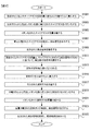
- FIG. 2 is a flowchart showing the flow of the analysis method of this embodiment.
- the flow rate adjustment unit 12 introduces a carrier gas having a set flow rate into the sample introduction unit 16 and the separation column 18.
- step S1003 is started.
- the ionization unit 33 ionizes the carrier gas that flows out of the separation column 18 and is introduced into the ionization unit.
- step S1005 is started.
- step S1005 the mass separation unit 35 mass-separates the ionized carrier gas.
- step S1007 is started.
- step S ⁇ b> 1007 the detection unit 36 detects the mass-separated carrier gas and outputs a detection signal to the control unit 50.
- step S1009 is started.
- step S1009 the analysis unit 52 analyzes the output detection signal and calculates the magnitude of the detection signal corresponding to the carrier gas.
- step S1011 is started.
- step S1011 the adjustment unit 512 adjusts the multiplication factor of the detection unit 36 based on the set flow rate of the carrier gas and the magnitude of the detection signal corresponding to the carrier gas.
- step S1013 is started.
- step S1013 the sample S is injected into the sample introduction unit 16 by a syringe, an autosampler, or the like.
- step S1015 is started.
- step S ⁇ b> 1015 the sample introduction unit 16 introduces the sample gas into the separation column 18.
- step S1017 is started.
- step S1017 the separation column 18 separates the introduced sample gas.
- step S1019 is started.
- step S1019 the ionization unit 33 ionizes the sample gas that has flowed out of the separation column 18 and introduced into the ionization unit 33.
- step S1021 is started.
- step S1021 the mass separation unit 35 mass-separates the ionized sample gas.
- step S1023 is started.
- the detection unit 36 detects the mass-separated sample gas and outputs a detection signal.
- step S1025 is started.
- step S1025 the analysis unit 52 analyzes the detection signal output from the detection unit 36 in step S1023, and the display unit 44 displays the analysis result.
- step S1025 ends, the process ends.
- the ionization unit 33 ionizes the carrier gas introduced into the separation column 18, and the mass separation unit 35 mass-separates ions generated by the ionization unit 33. Then, the detection unit 36 amplifies and detects ions separated by the mass separation unit 35 at a predetermined multiplication factor and outputs a detection signal, and the analysis unit 52 outputs the detection signal output from the detection unit 36. Analyzing, the adjustment unit 512 increases the detection unit 36 based on the magnitude of the detection signal corresponding to the carrier gas detected by the detection unit 36 when the carrier gas having a predetermined flow rate is introduced into the separation column 18. Adjust the magnification.
- the introduction of a standard sample such as PFTBA is not necessarily required, and the mass spectrometer can be adjusted.
- the amount of volatilization of the standard sample such as PFTBA differs depending on the temperature, and the amount of standard sample introduced into the ion source varies.
- the analyzer 1 of this embodiment does not need this.
- the adjustment unit 512 detects the carrier gas detected by the detection unit 36 when the carrier gas having the set flow rate is introduced into the separation column 18.
- the multiplication factor of the detection unit 36 is adjusted based on the magnitude of the signal. Thereby, based on the data obtained by the past measurement etc., a multiplication factor can be adjusted appropriately.
- the adjustment unit 512 of the present modified example detects from the flow rate of the carrier gas measured by the sensor 14 based on the data corresponding to the correspondence table stored in the storage unit 43 in advance, corresponding to the measured flow rate of the carrier gas. A target value of the signal magnitude is calculated.
- FIG. 3 is a diagram showing the correspondence table T referred to by the adjustment unit 512.
- the correspondence table T shows the flow rate of the carrier gas and the magnification for correcting the target value of the magnitude of the detection signal of the carrier gas corresponding to the flow rate of the carrier gas.
- the adjustment unit 512 multiplies the target value of the magnitude of the detection signal corresponding to the carrier gas at the reference flow rate (1 ml / min) by the magnification, and at any flow rate shown in the correspondence table T. Calculate the target value.
- values obtained by approximating the values shown in the correspondence table T with a straight line or the like and interpolating or extrapolating can be used.
- the adjustment unit 512 refers to the data corresponding to the correspondence table T and the magnification for correction corresponding to 0.5 ml / min. Get 0.4.
- the storage unit 43 stores a target value at a reference flow rate of 1.0 ml / min.
- the adjustment unit 512 multiplies the target value at the reference flow rate by 0.4, and sets 0.4 ml / min as the target value of the magnitude of the detection signal of the carrier gas.
- the adjustment unit 512 controls the voltage applied to the detection unit 36 so as to approach the set target value.
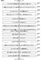
- FIG. 4 is a flowchart showing the flow of the analysis method of this modification.
- Steps S2001 to S2009 are the same as steps S1001 to 1009 in the above-described embodiment, and thus description thereof is omitted.
- step S2009 is completed.
- step S2011 the sensor 14 measures the flow rate of the carrier gas.
- step S2013 is started.
- step S2013 the adjustment unit 512 refers to the correspondence table T and calculates the target value of the magnitude of the detection signal corresponding to the carrier gas from the measured flow rate of the carrier gas.
- step S2015 is started.
- step S2015 the adjustment unit 512 adjusts the multiplication factor of the detection unit 36 based on the measured flow rate of the carrier gas and the magnitude of the detection signal corresponding to the carrier gas.
- step S2017 is started. Steps S2017 to S2029 are the same as steps S1013 to S1025, and a description thereof will be omitted.
- the analyzer 1 of this modification includes a sensor 14 that is a flow rate measurement unit that measures the flow rate of the carrier gas, and the adjustment unit 512 determines the flow rate of the measured carrier gas and the carrier gas detected by the detection unit 36.
- the multiplication factor of the detection unit 36 is adjusted based on the magnitude of the corresponding detection signal. Thereby, the multiplication factor of the detection unit 36 can be adjusted with higher accuracy based on the actually measured flow rate of the carrier gas.
- the adjustment unit 512 calculates a target value of the magnitude of the detection signal corresponding to the measured carrier gas flow rate based on the data of the correspondence table T obtained in advance. Thereby, even if it is a case where the flow volume of the measured carrier gas takes various values, the multiplication factor of the detection part 36 can be set appropriately.
- the adjustment unit 512 sets the voltage applied to the detection unit 36 and adjusts the multiplication factor.
- the voltage applied to the ion adjustment unit 34 and the mass separation unit 35 may be set.
- the adjustment unit 512 can adjust the voltage applied to the lens electrode of the ion adjustment unit 34 so that the detected intensity of the carrier gas is the highest. Thereby, the detection sensitivity at the time of analyzing the sample S can be raised.
- the adjustment unit 512 adjusts the voltage applied to at least one electrode in the ion transport system selected from the group consisting of a lens electrode, an ion guide, and a quadrupole mass filter based on the magnitude of the detection signal of the carrier gas. In addition, the detection sensitivity when analyzing the sample S can be adjusted.
- the adjustment unit 512 detects the magnitude of the detection signal corresponding to the carrier gas detected by the detection unit 36 when the carrier gas having a predetermined flow rate is introduced into the separation column 18.
- the voltage applied to the ion transport system such as the lens electrode, ion guide, and quadrupole mass filter is adjusted based on the above.
- a program for realizing the information processing function of the analysis apparatus 1 is recorded on a computer-readable recording medium, and the measurement, analysis, and display processes including the adjustment by the adjustment unit 512 described above are recorded on the recording medium.
- a program related to control of processing related thereto may be read into a computer system and executed.
- the “computer system” includes an OS (Operating System) and hardware of peripheral devices.
- the “computer-readable recording medium” refers to a portable recording medium such as a flexible disk, a magneto-optical disk, an optical disk, and a memory card, and a storage device such as a hard disk built in the computer system.
- the “computer-readable recording medium” dynamically holds a program for a short time like a communication line when transmitting a program via a network such as the Internet or a communication line such as a telephone line.
- a volatile memory in a computer system serving as a server or a client in that case may be included and a program that holds a program for a certain period of time.
- the above program may be for realizing a part of the functions described above, or may be realized by a combination with the program already recorded in the computer system. .
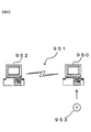
- FIG. 5 is a diagram showing this state.
- the PC 950 is provided with a program via the CD-ROM 953. Further, the PC 950 has a connection function with the communication line 951.
- a computer 952 is a server computer that provides the program, and stores the program in a recording medium such as a hard disk.
- the communication line 951 is a communication line such as the Internet or personal computer communication, or a dedicated communication line.
- the computer 952 reads the program using the hard disk and transmits the program to the PC 950 via the communication line 951. That is, the program is transmitted as a data signal by a carrier wave and transmitted via the communication line 951.
- the program can be supplied as a computer-readable computer program product in various forms such as a recording medium and a carrier wave.
- the carrier gas and the sample S separated by the separation column 18 are ionized, ions generated by ionization are mass separated, and the mass separated ions are detected.
- the carrier gas having a predetermined flow rate is introduced into the separation column 18 into the processing device of the analyzer 1 that amplifies and detects at a predetermined multiplication factor by the unit 36, outputs a detection signal, and analyzes the output detection signal.
- the multiplication factor of the detection unit and / or the voltage applied to the electrode in the ion transport system based on the magnitude of the detection signal corresponding to the carrier gas detected by the detection unit 36.
- the program is included. Thereby, the introduction of a standard sample such as PFTBA is not necessarily required, and the mass spectrometer can be adjusted.
- the processing executed as a program according to the present invention mainly includes step S1009 and step S1011 in FIG. 2, for example, the program is executed by the control unit 50 in FIG.
- the program is stored in the control unit 50 or stored in the storage unit 43 in advance. That is, the program according to the present invention ionizes the sample separated by the carrier gas and the separation column 18, mass-separates ions generated by ionization, and the mass-separated ions are detected at a predetermined multiplication factor by a detector.
- the multiplication factor of the detector and / or the voltage applied to the electrode in the ion transport system during mass separation is appropriately calculated.
- the present invention is not limited to the contents of the above embodiment.
- Other embodiments conceivable within the scope of the technical idea of the present invention are also included in the scope of the present invention.
Landscapes
- Chemical & Material Sciences (AREA)
- Analytical Chemistry (AREA)
- Physics & Mathematics (AREA)
- Health & Medical Sciences (AREA)
- Life Sciences & Earth Sciences (AREA)
- Biochemistry (AREA)
- General Health & Medical Sciences (AREA)
- General Physics & Mathematics (AREA)
- Immunology (AREA)
- Pathology (AREA)
- Electrochemistry (AREA)
- Chemical Kinetics & Catalysis (AREA)
- Other Investigation Or Analysis Of Materials By Electrical Means (AREA)
Abstract
分析装置は、分離カラムに導入されたキャリアガスをイオン化するイオン化部と、イオン化部で生成されたイオンを質量分離する質量分離部と、質量分離部で質量分離されたイオンを、所定の増倍率で増幅して検出し、検出信号を出力する検出部と、検出部から出力された検出信号を解析する解析部と、検出部で検出されたキャリアガスに対応する検出信号の大きさに基づいて、検出部の増倍率および/または質量分離部のイオン輸送系における電極に印加される電圧の調整を行う調整部とを備える。
Description
本発明は、分析装置、分析方法およびプログラムに関する。
ガスグロマトグラフ質量分析計(以下、適宜GC-MSと呼ぶ)を用いた分析では、測定における精度や感度を維持、向上させるため、検出器に印加する電圧を調整する等、装置の各部の調整が行われる。
例えば、GC-MSにおける検出器に印加される電圧の調整では、GC-MSのイオン源にパーフルオロトリブチルアミン(perfluorotributylamine:以下、PFTBAと呼ぶ)等の標準試料を導入し、この標準試料を質量分析して得られた検出強度に基づいて調整を行っていた(特許文献1参照)。
しかし、PFTBA等の標準試料は、室温により導入される量が変化してしまう等の問題があった。
本発明の第1の態様によると、分析装置は、分離カラムに導入されたキャリアガスをイオン化するイオン化部と、前記イオン化部で生成されたイオンを質量分離する質量分離部と、前記質量分離部で質量分離された前記イオンを、所定の増倍率で増幅して検出し、検出信号を出力する検出部と、前記検出部から出力された前記検出信号を解析する解析部と、前記検出部で検出された前記キャリアガスに対応する前記検出信号の大きさに基づいて、前記検出部の前記増倍率および/または前記質量分離部のイオン輸送系における電極に印加される電圧の調整を行う調整部とを備える。
本発明の第2の態様によると、第1の態様の分析装置において、前記調整部は、設定された流量の前記キャリアガスが前記分離カラムに導入された際、前記検出部で検出された前記キャリアガスに対応する前記検出信号の大きさに基づいて前記調整を行うことが好ましい。
本発明の第3の態様によると、第1の態様の分析装置は、前記キャリアガスの流量を測定する流量測定部を備え、前記調整部は、測定された前記キャリアガスの流量と、前記検出部で検出された前記キャリアガスに対応する前記検出信号の大きさとに基づいて、前記調整を行うことが好ましい。
本発明の第4の態様によると、第1から第3までのいずれかの態様の分析装置において、前記イオン輸送系は、レンズ電極、イオンガイドおよび四重極マスフィルタからなる群から選択される少なくとも一つであることが好ましい。
本発明の第5の態様によると、分析方法は、分離カラムに導入されたキャリアガスをイオン化することと、イオン化により生成されたイオンを質量分離することと、質量分離された前記イオンを、検出器により所定の増倍率で増幅して検出し、検出信号を出力することと、出力された前記検出信号を解析することと、前記検出器で検出された前記キャリアガスに対応する前記検出信号の大きさに基づいて、前記検出器の前記増倍率および/または前記質量分離の際のイオン輸送系の電極に印加される電圧の調整を行うこととを備える。
本発明の第6の態様によると、第5の態様の分析方法において、設定された流量の前記キャリアガスが前記分離カラムに導入された際、前記検出器で検出された前記キャリアガスに対応する前記検出信号の大きさに基づいて前記調整が行われることが好ましい。
本発明の第7の態様によると、第5の態様の分析方法において、前記キャリアガスの流量を測定することをさらに備え、測定された前記キャリアガスの流量と、前記検出器で検出された前記キャリアガスに対応する前記検出信号の大きさとに基づいて、前記調整が行われることが好ましい。
本発明の第8の態様によると、第5から第7までのいずれかの態様の分析方法において、前記イオン輸送系は、レンズ電極、イオンガイドおよび四重極マスフィルタからなる群から選択される少なくとも一つであることが好ましい。
本発明の第9の態様によると、プログラムは、分離カラムに導入されたキャリアガスをイオン化し、イオン化により生成されたイオンを質量分離し、質量分離された前記イオンを、検出器により所定の増倍率で増幅して検出し、その検出信号を出力し、出力された前記検出信号を解析する分析装置の処理装置に、前記検出器で検出された前記キャリアガスに対応する前記検出信号の大きさに基づいて、前記検出器の前記増倍率および/または前記質量分離の際のイオン輸送系における電極に印加される電圧を調整する調整処理を行わせるためのものである。
本発明の第2の態様によると、第1の態様の分析装置において、前記調整部は、設定された流量の前記キャリアガスが前記分離カラムに導入された際、前記検出部で検出された前記キャリアガスに対応する前記検出信号の大きさに基づいて前記調整を行うことが好ましい。
本発明の第3の態様によると、第1の態様の分析装置は、前記キャリアガスの流量を測定する流量測定部を備え、前記調整部は、測定された前記キャリアガスの流量と、前記検出部で検出された前記キャリアガスに対応する前記検出信号の大きさとに基づいて、前記調整を行うことが好ましい。
本発明の第4の態様によると、第1から第3までのいずれかの態様の分析装置において、前記イオン輸送系は、レンズ電極、イオンガイドおよび四重極マスフィルタからなる群から選択される少なくとも一つであることが好ましい。
本発明の第5の態様によると、分析方法は、分離カラムに導入されたキャリアガスをイオン化することと、イオン化により生成されたイオンを質量分離することと、質量分離された前記イオンを、検出器により所定の増倍率で増幅して検出し、検出信号を出力することと、出力された前記検出信号を解析することと、前記検出器で検出された前記キャリアガスに対応する前記検出信号の大きさに基づいて、前記検出器の前記増倍率および/または前記質量分離の際のイオン輸送系の電極に印加される電圧の調整を行うこととを備える。
本発明の第6の態様によると、第5の態様の分析方法において、設定された流量の前記キャリアガスが前記分離カラムに導入された際、前記検出器で検出された前記キャリアガスに対応する前記検出信号の大きさに基づいて前記調整が行われることが好ましい。
本発明の第7の態様によると、第5の態様の分析方法において、前記キャリアガスの流量を測定することをさらに備え、測定された前記キャリアガスの流量と、前記検出器で検出された前記キャリアガスに対応する前記検出信号の大きさとに基づいて、前記調整が行われることが好ましい。
本発明の第8の態様によると、第5から第7までのいずれかの態様の分析方法において、前記イオン輸送系は、レンズ電極、イオンガイドおよび四重極マスフィルタからなる群から選択される少なくとも一つであることが好ましい。
本発明の第9の態様によると、プログラムは、分離カラムに導入されたキャリアガスをイオン化し、イオン化により生成されたイオンを質量分離し、質量分離された前記イオンを、検出器により所定の増倍率で増幅して検出し、その検出信号を出力し、出力された前記検出信号を解析する分析装置の処理装置に、前記検出器で検出された前記キャリアガスに対応する前記検出信号の大きさに基づいて、前記検出器の前記増倍率および/または前記質量分離の際のイオン輸送系における電極に印加される電圧を調整する調整処理を行わせるためのものである。
本発明によれば、キャリアガスを利用して分析を行う分析装置において、PFTBA等の標準試料の導入を必ずしも必要とせず、質量分析計の調整を行うことができる。
以下、図を参照して本発明を実施するための形態について説明する。以下の実施形態の分析装置は、所定の流量のキャリアガスが分離カラムに導入された際、検出部で検出されたキャリアガスに対応する検出信号の大きさに基づいて、検出部の増倍率等、質量分析計の各部を調整するものである。
(全体の構成)
図1は、本実施形態の分析装置の構成を示す概念図である。分析装置1は、ガスクロマトグラフ質量分析計(GC-MS)であり、分離部10と、接続部20と、質量分析部30と、情報処理部40とを備える。
図1は、本実施形態の分析装置の構成を示す概念図である。分析装置1は、ガスクロマトグラフ質量分析計(GC-MS)であり、分離部10と、接続部20と、質量分析部30と、情報処理部40とを備える。
分離部10は、キャリアガスが格納されたガス格納容器Gと、第1キャリアガス流路11と、流量調整部12と、第2キャリアガス流路13と、センサー14と、第3キャリアガス流路15と、試料Sが導入される試料導入部16と、カラム温度調節部17と、分離カラム18とを備える。
接続部20は、接続流路21と、ヒーター22と、ヒーター支持部23とを備える。
質量分析部30は、真空容器31と、排気口32と、イオン化部33と、イオン調整部34と、質量分離部35と、検出部36とを備える。イオン調整部34および質量分離部35は、イオン輸送系を構成する。
情報処理部40は、入力部41と、通信部42と、記憶部43と、表示部44と、制御部50とを備える。制御部50は、装置制御部51と、解析部52とを備える。装置制御部51は、流量制御部511と、調整部512とを備える。
(分離部10)
分離部10は、ガスクロマトグラフ等のキャリアガスを利用して試料を分離する分離分析装置を備え、試料Sに含まれる成分を物理的および/または化学的特性に基づいて分離する。以下では、分離部10はガスクロマトグラフとして説明する。分離カラム18に導入される際に、試料Sはガスとなっているが、これを試料ガスと呼ぶ。
分離部10は、ガスクロマトグラフ等のキャリアガスを利用して試料を分離する分離分析装置を備え、試料Sに含まれる成分を物理的および/または化学的特性に基づいて分離する。以下では、分離部10はガスクロマトグラフとして説明する。分離カラム18に導入される際に、試料Sはガスとなっているが、これを試料ガスと呼ぶ。
分離部10のガス格納容器Gは、キャリアガスを格納し、第1キャリアガス流路11と接続されている。キャリアガスの種類は、キャリアガスを質量分析部30のイオン化部33でイオン化し、検出部36で検出することができれば特に限定されないが、安全性や線速度の観点から、ヘリウムが好ましい。ガス格納容器Gから第1キャリアガス流路11に導入されたキャリアガスは、流量調整部12に導入される。
分離部10の流量調整部12は、圧力調整器や流量制御弁等の調整器を備え、第1キャリアガス流路11および第2キャリアガス流路13と接続されている。流量調整部12は、試料導入部16、および試料導入部16を介して分離カラム18に導入されるキャリアガスの流量を調整する。流量調整部12から第2キャリアガス流路13に導入されたキャリアガスは、センサー14に導入される。
分離部10のセンサー14は、流量を直接的または間接的に測定する流量測定部として働き、圧力センサーおよび/または流量センサーを備え、通過するキャリアガスの圧力および/または流量を測定する。センサー14は、第2キャリアガス流路13と第3キャリアガス流路15と接続されている。センサー14は、測定されたキャリアガスの圧力および/または流量を示す信号を情報処理部40の制御部50に出力する(矢印A1)。センサー14から第3キャリアガス流路15に導入されたキャリアガスは、試料導入部16に導入される。
なお、流量調整部12とセンサー14とを一体的に構成してもよい。
なお、流量調整部12とセンサー14とを一体的に構成してもよい。
分離部10の試料導入部16は、試料気化室等の試料を導入する室を備え、不図示のシリンジやオートサンプラー等の注入器により注入された試料Sを一時的に収容し、試料Sが液体の場合は気化させて、試料ガスを分離カラム18に導入する。後述するように、キャリアガスの検出を行う際に分離カラム18へのキャリアガスの流量が制御できれば、試料Sの導入法は特に限定されず、スプリット導入法やスプリットレス導入法等を適宜用いることができる。
分離部10の分離カラム18は、キャピラリーカラム等のカラムを備える。分離カラム18は、カラムオーブン等を備えるカラム温度調節部17により数百℃以下等に温度制御されている。試料ガスの各成分は、キャリアガスを含む移動相と、分離カラム18の固定相との間の分配係数等に基づいて分離され、分離された試料ガスの各成分は異なる時間に分離カラム18から流出し、接続部20に導入される。以下の実施形態では、試料導入部16に試料Sが注入された時間等の分析の開始に対応する時間から、試料Sの特定の成分が検出されるまでの時間を、当該成分の保持時間と呼ぶ。
(接続部20)
接続部20は、分離部10と質量分析部30とを接続する部分であり、分離部10の分離カラム18から流出したガスを質量分析部30のイオン化部33へと供給する。接続部20は、分離カラム18がキャピラリーカラムの場合、直接結合法により分離部10と質量分析部30とを接続することが好ましい。
接続部20は、分離部10と質量分析部30とを接続する部分であり、分離部10の分離カラム18から流出したガスを質量分析部30のイオン化部33へと供給する。接続部20は、分離カラム18がキャピラリーカラムの場合、直接結合法により分離部10と質量分析部30とを接続することが好ましい。
接続部20の接続流路21は、ヒーターブロック等を含むヒーター支持部23に支持されたヒーターにより温度を調整される。分離カラム18から流出されたガスは、接続流路21を通過すると、イオン化部33に導入される。
(質量分析部30)
質量分析部30は、質量分析計を備え、イオン化部33に導入されたガスおよび気体状の分子をイオン化し、質量分離して検出する。イオン化部33で生成されたイオンの経路を矢印A3で模式的に示した。
なお、以下では質量分析計として1つの四重極マスフィルタにより質量分離を行うシングル四重極質量分析計の例を用いて説明する。しかし、真空度等の所望の分析条件を維持しながら分離部10から導入された試料Sおよびキャリアガスをイオン化することができれば、質量分析部30を構成する質量分析計の種類は特に限定されず、例えば磁場型、イオントラップ型、飛行時間型等の質量分析計またはタンデム質量分析計を用いることができる。
質量分析部30は、質量分析計を備え、イオン化部33に導入されたガスおよび気体状の分子をイオン化し、質量分離して検出する。イオン化部33で生成されたイオンの経路を矢印A3で模式的に示した。
なお、以下では質量分析計として1つの四重極マスフィルタにより質量分離を行うシングル四重極質量分析計の例を用いて説明する。しかし、真空度等の所望の分析条件を維持しながら分離部10から導入された試料Sおよびキャリアガスをイオン化することができれば、質量分析部30を構成する質量分析計の種類は特に限定されず、例えば磁場型、イオントラップ型、飛行時間型等の質量分析計またはタンデム質量分析計を用いることができる。
質量分析部30の真空容器31は、排気口32を備える。排気口32は、ターボ分子ポンプ等の、10-2Pa以下等の高真空が実現可能なポンプおよびその補助ポンプを含む不図示の真空排気系と接続されている。図1では、真空容器31の内部の気体が排出される点を矢印A4で模式的に示した。
質量分析部30のイオン化部33は、イオン源を備え、イオン化部33に導入された試料Sおよびキャリアガスをイオン化する。イオン化部33は、電子イオン化によりイオン化を行う場合、不図示のイオン化室、熱電子生成用フィラメントおよびトラップ電極等を含み、熱電子生成用フィラメントで生成された熱電子を、トラップ電極に印加された数十eV等の電圧で加速し、イオン化室内の分子に照射してイオンを生成する。イオン化部33で生成されたイオンはイオン調整部34に導入される。
なお、イオン化の方法は特に限定されず、例えば化学イオン化法を用いてもよい。
なお、イオン化の方法は特に限定されず、例えば化学イオン化法を用いてもよい。
質量分析部30のイオン調整部34は、レンズ電極やイオンガイド等を備え、これらのレンズ電極やイオンガイドに印加された電圧によるイオンへの電磁気学的作用により、当該イオンを収束させる等の調整を行う。イオン調整部34から出射されたイオンは質量分離部35に導入される。
質量分析部30の質量分離部35は、四重極マスフィルタを備え、導入されたイオンを質量分離する。質量分離部35は、四重極マスフィルタに印加された電圧により、m/zの値に基づいてイオンを選択的に通過させる。質量分離部35で質量分離されたイオンは検出部36に入射する。
質量分析部30の検出部36は、コンバージョンダイノードが設置された電子増倍管等のイオン検出器を備え、入射したイオンを検出する。電子増倍管としては、二次電子増倍管や光電子増倍管等が用いられる。検出部36は、検出するイオンが入射、衝突した後、設定された増倍率により得られた検出信号を、不図示のA/D変換器によりA/D変換し、デジタル化された検出信号を測定データとして情報処理部40の制御部50に出力する(矢印A5)。
二次電子増倍管や光電子増倍管等の電子増倍管に入射したイオンにより生成される検出信号の大きさは、これらの電子増倍管において二次電子等を加速するために印加された電圧で定まる増倍率により異なる。この増倍率が高過ぎると、検出信号が大き過ぎて飽和してしまい、正確な測定データを得ることができない。逆に、この増倍率が低すぎると、試料Sの少なくとも一部の成分が検出できなかったり、検出信号が小さすぎてS/N比が悪化してしまう。後述するように、検出部36における増倍率は、情報処理部40の調整部512により調整され、適切な値に設定される(矢印A6)。
(情報処理部40)
情報処理部40は、電子計算機等の情報処理装置を備え、ユーザーとのインターフェースとなる他、様々なデータに関する通信、記憶、演算等の処理を行う。
なお、情報処理部40は、測定部100と一体となった一つの装置として構成してもよい。また、分析装置1が用いるデータの一部または全部は遠隔のサーバ等に保存してもよく、分析装置1が行う演算処理の一部または全部は遠隔のサーバ等で行ってもよい。
情報処理部40は、電子計算機等の情報処理装置を備え、ユーザーとのインターフェースとなる他、様々なデータに関する通信、記憶、演算等の処理を行う。
なお、情報処理部40は、測定部100と一体となった一つの装置として構成してもよい。また、分析装置1が用いるデータの一部または全部は遠隔のサーバ等に保存してもよく、分析装置1が行う演算処理の一部または全部は遠隔のサーバ等で行ってもよい。
入力部41は、マウス、キーボード、各種ボタンおよび/またはタッチパネル等の入力装置を含んで構成される。入力部41は、キャリアガスの種類等の測定部100の動作の制御に必要な情報、および制御部50の行う処理に必要な情報等を、ユーザーから受け付ける。
通信部42は、インターネット等の無線や有線接続により通信可能な通信装置を含んで構成され、解析部52が作成したm/zと該m/zのイオンに対する検出信号の大きさの関係を示すマススペクトル等の、解析により得られたデータ等を送信したり、適宜必要なデータを送受信する。
記憶部43は、不揮発性の記憶媒体で構成され、調整部512が検出部36等の調整を行うためのパラメータ、検出部36からの検出信号に基づく測定データ、制御部50が処理を実行するためのプログラム、および解析部52が作成したマススペクトル等の、解析により得られたデータ等を記憶する。
表示部44は、液晶モニタ等の表示装置を含んで構成され、分析条件や、検出部36からの検出信号に基づく測定データ、および解析部52が作成したマススペクトル等の、解析により得られたデータ等を、表示装置に表示する。
(制御部50)
制御部50は、CPU等のプロセッサからなり、測定部100の各部の動作を制御したり、検出部36から出力された検出信号を測定データとして処理する。なお、プロセッサにはFPGAも含まれる。
制御部50は、CPU等のプロセッサからなり、測定部100の各部の動作を制御したり、検出部36から出力された検出信号を測定データとして処理する。なお、プロセッサにはFPGAも含まれる。
(装置制御部51)
制御部50の装置制御部51は、測定部100の各部の動作を制御する。
制御部50の装置制御部51は、測定部100の各部の動作を制御する。
(流量制御部511)
装置制御部51の流量制御部511は、センサー14から出力されたキャリアガスの圧力および/または流量に基づいて流量調整部12を制御し、キャリアガスの流量を調整する(矢印A7)。流量制御部511は、検出部36の電圧調整の際に設定するキャリアガスの流量の値を取得する。この流量の値は、予め記憶部43に記憶されており、例えば1.0ml/min等であるが、特に限定されない。流量制御部511は、センサー14から出力された流量またはセンサー14から出力された圧力から算出された流量(以下、適宜これらの流量を、測定された流量と呼ぶ)と、設定されたキャリアガスの流量とを比較し、キャリアガスの流量が設定された値に近づくように流量調整部12を制御する。
装置制御部51の流量制御部511は、センサー14から出力されたキャリアガスの圧力および/または流量に基づいて流量調整部12を制御し、キャリアガスの流量を調整する(矢印A7)。流量制御部511は、検出部36の電圧調整の際に設定するキャリアガスの流量の値を取得する。この流量の値は、予め記憶部43に記憶されており、例えば1.0ml/min等であるが、特に限定されない。流量制御部511は、センサー14から出力された流量またはセンサー14から出力された圧力から算出された流量(以下、適宜これらの流量を、測定された流量と呼ぶ)と、設定されたキャリアガスの流量とを比較し、キャリアガスの流量が設定された値に近づくように流量調整部12を制御する。
(調整部512)
装置制御部51の調整部512は、設定されたキャリアガスの流量に基づいて検出部36の増倍率を調整する。調整部512は、入力部41からの入力等により得られたキャリアガスの種類を取得する。記憶部43には、検出部36の電圧調整の際に設定するキャリアガスの流量の値に対応させて、当該電圧調整の際の、キャリアガスに対応するイオンの検出信号の大きさの目標値が記憶されている。ここで、この目標値は、所定のキャリアガスに対応するイオンの検出信号の大きさを示すものであれば、選択イオンモニタリング(Selected Ion Monitoring;SIM)における検出強度やマススペクトル上の所定のキャリアガスに対応するm/zのイオンにおけるピークの強度、面積等、特に限定されない。調整部512は、検出部36からの、キャリアガスに対応するm/zのイオンの検出信号の大きさがこの目標値に近づくように、検出部36に印加される電圧を制御し、増倍率を設定する。調整部512は、キャリアガスの検出信号の大きさが数秒~数分等の所定の時間、目標値の90%~110%等の所定の数値範囲に収まった場合、増倍率の設定を完了することが好ましい。
装置制御部51の調整部512は、設定されたキャリアガスの流量に基づいて検出部36の増倍率を調整する。調整部512は、入力部41からの入力等により得られたキャリアガスの種類を取得する。記憶部43には、検出部36の電圧調整の際に設定するキャリアガスの流量の値に対応させて、当該電圧調整の際の、キャリアガスに対応するイオンの検出信号の大きさの目標値が記憶されている。ここで、この目標値は、所定のキャリアガスに対応するイオンの検出信号の大きさを示すものであれば、選択イオンモニタリング(Selected Ion Monitoring;SIM)における検出強度やマススペクトル上の所定のキャリアガスに対応するm/zのイオンにおけるピークの強度、面積等、特に限定されない。調整部512は、検出部36からの、キャリアガスに対応するm/zのイオンの検出信号の大きさがこの目標値に近づくように、検出部36に印加される電圧を制御し、増倍率を設定する。調整部512は、キャリアガスの検出信号の大きさが数秒~数分等の所定の時間、目標値の90%~110%等の所定の数値範囲に収まった場合、増倍率の設定を完了することが好ましい。
例えば、キャリアガスがヘリウムの場合、調整部512は、イオン化されたヘリウムのSIMにより得られた検出強度が目標値に近づくように検出部36の印加電圧を制御する。SIMでは、特定のm/zを有するイオンの量の時間的変化が検出される。あるいは、調整部512は、全イオンモニタリング(Total Ion Monitoring;TIM)等のm/zを走査することにより得られたマススペクトルにおいて、イオン化されたヘリウムに対応するピークの面積が目標値に近づくように検出部36の印加電圧を制御してもよい。
(解析部520)
制御部50の解析部52は、検出部36からの検出信号を測定データとして処理し、解析する。解析部52は、質量分離部35が質量分離した、試料Sやキャリアガスのイオンのm/zと、検出信号の強度とを対応させて、当該イオンの検出強度を算出する。また、解析部52は、検出信号の強度とm/zとを対応させたデータをマススペクトルに対応するデータとして構築し、記憶部43に記憶させる。解析部52は、必要に応じて、マススペクトルの各ピークのピーク強度やピークに対応する面積を算出し、各ピークに対応する成分の検出信号の大きさを算出する。
制御部50の解析部52は、検出部36からの検出信号を測定データとして処理し、解析する。解析部52は、質量分離部35が質量分離した、試料Sやキャリアガスのイオンのm/zと、検出信号の強度とを対応させて、当該イオンの検出強度を算出する。また、解析部52は、検出信号の強度とm/zとを対応させたデータをマススペクトルに対応するデータとして構築し、記憶部43に記憶させる。解析部52は、必要に応じて、マススペクトルの各ピークのピーク強度やピークに対応する面積を算出し、各ピークに対応する成分の検出信号の大きさを算出する。
この他、試料Sの分析では、解析部52は、得られた測定データから、過去のデータとの対応に基づいてマススペクトルのピークに対応する成分を同定したり、SIMで得られた検出強度から目的の成分を定量したりする。解析部52は、構築したマススペクトルのデータや解析により得られた情報を表示する表示画像を生成し、表示部44に表示させる。
(分析方法の手順)
図2は、本実施形態の分析方法の流れを示すフローチャートである。ステップS1001において、流量調整部12は、設定された流量のキャリアガスを試料導入部16および分離カラム18に導入する。ステップS1001が終了したら、ステップS1003が開始される。ステップS1003において、イオン化部33は、分離カラム18から流出しイオン化部に導入されたキャリアガスをイオン化する。ステップS1003が終了したらステップS1005が開始される。
図2は、本実施形態の分析方法の流れを示すフローチャートである。ステップS1001において、流量調整部12は、設定された流量のキャリアガスを試料導入部16および分離カラム18に導入する。ステップS1001が終了したら、ステップS1003が開始される。ステップS1003において、イオン化部33は、分離カラム18から流出しイオン化部に導入されたキャリアガスをイオン化する。ステップS1003が終了したらステップS1005が開始される。
ステップS1005において、質量分離部35は、イオン化されたキャリアガスを質量分離する。ステップS1005が終了したら、ステップS1007が開始される。ステップS1007において、検出部36は、質量分離されたキャリアガスを検出し、検出信号を制御部50に出力する。ステップS1007が終了したら、ステップS1009が開始される。
ステップS1009において、解析部52は、出力された検出信号を解析し、キャリアガスに対応する検出信号の大きさを算出する。ステップS1009が終了したら、ステップS1011が開始される。ステップS1011において、調整部512は、設定されたキャリアガスの流量と、キャリアガスに対応する検出信号の大きさに基づいて、検出部36の増倍率を調整する。ステップS1011が終了したら、ステップS1013が開始される。
ステップS1013において、シリンジやオートサンプラー等により、試料Sが試料導入部16に注入される。ステップS1013が終了したら、ステップS1015が開始される。ステップS1015において、試料導入部16は、試料ガスを分離カラム18に導入する。ステップS1015が終了したら、ステップS1017が開始される。
ステップS1017において、分離カラム18は、導入された試料ガスを分離する。ステップS1017が終了したら、ステップS1019が開始される。ステップS1019において、イオン化部33は、分離カラム18から流出しイオン化部33に導入された試料ガスをイオン化する。ステップS1019が終了したら、ステップS1021が開始される。
ステップS1021において、質量分離部35は、イオン化された試料ガスを質量分離する。ステップS1021が終了したら、ステップS1023が開始される。ステップS1023において、検出部36は、質量分離された試料ガスを検出し、検出信号を出力する。ステップS1023が終了したら、ステップS1025が開始される。
ステップS1025において、解析部52は、ステップS1023において検出部36から出力された検出信号を解析し、表示部44は解析結果を表示する。ステップS1025が終了したら、処理が終了される。
上述の実施の形態によれば、次の作用効果が得られる。
(1)本実施形態の分析装置1および分析方法は、イオン化部33が、分離カラム18に導入されたキャリアガスをイオン化し、質量分離部35が、イオン化部33で生成されたイオンを質量分離し、検出部36が、質量分離部35で質量分離されたイオンを所定の増倍率で増幅して検出して検出信号を出力し、解析部52が、検出部36から出力された検出信号を解析し、調整部512が、所定の流量のキャリアガスが分離カラム18に導入された際、検出部36で検出されたキャリアガスに対応する検出信号の大きさに基づいて、検出部36の増倍率を調整する。これにより、PFTBA等の標準試料の導入を必ずしも必要とせず、質量分析計の調整を行うことができる。また、従来の標準試料を用いた検出器の調整では、温度によりPFTBA等の標準試料の揮発量が異なり、イオン源に導入される標準試料の導入量がばらつくため、室温の変化への対応をしなければいけなかったが、本実施形態の分析装置1ではその必要が無い。
(1)本実施形態の分析装置1および分析方法は、イオン化部33が、分離カラム18に導入されたキャリアガスをイオン化し、質量分離部35が、イオン化部33で生成されたイオンを質量分離し、検出部36が、質量分離部35で質量分離されたイオンを所定の増倍率で増幅して検出して検出信号を出力し、解析部52が、検出部36から出力された検出信号を解析し、調整部512が、所定の流量のキャリアガスが分離カラム18に導入された際、検出部36で検出されたキャリアガスに対応する検出信号の大きさに基づいて、検出部36の増倍率を調整する。これにより、PFTBA等の標準試料の導入を必ずしも必要とせず、質量分析計の調整を行うことができる。また、従来の標準試料を用いた検出器の調整では、温度によりPFTBA等の標準試料の揮発量が異なり、イオン源に導入される標準試料の導入量がばらつくため、室温の変化への対応をしなければいけなかったが、本実施形態の分析装置1ではその必要が無い。
(2)本実施形態の分析装置1および分析方法において、調整部512は、設定された流量のキャリアガスが分離カラム18に導入された際、検出部36で検出されたキャリアガスに対応する検出信号の大きさに基づいて検出部36の増倍率を調整する。これにより、過去の測定等で得られたデータに基づき、適切に増倍率を調整することができる。
次のような変形も本発明の範囲内であり、上述の実施形態と組み合わせることが可能である。以下の変形例において、上述の実施形態と同様の構造、機能を示す部位に関しては、同一の符号で参照し、適宜説明を省略する。
(変形例1)
上述の実施形態では、設定されたキャリアガスの流量に基づいて、検出部36の増倍率を調整したが、測定されたキャリアガスの流量に基づいて検出部36の増倍率を調整してもよい。
(変形例1)
上述の実施形態では、設定されたキャリアガスの流量に基づいて、検出部36の増倍率を調整したが、測定されたキャリアガスの流量に基づいて検出部36の増倍率を調整してもよい。
本変形例の調整部512は、センサー14により測定されたキャリアガスの流量から、予め記憶部43に記憶された対応表に対応するデータに基づいて、測定されたキャリアガスの流量に対応する検出信号の大きさの目標値を算出する。
図3は、調整部512が参照する対応表Tを示す図である。対応表Tではキャリアガスの流量と、当該キャリアガスの流量に対応する、キャリアガスの検出信号の大きさの目標値を補正するための倍率が示されている。調整部512は、基準となる流量(1ml/min)のときのキャリアガスに対応する検出信号の大きさの目標値に、当該倍率を乗算することで対応表Tに示された任意の流量における目標値を算出する。対応表Tに記載されていない流量に対しては、適宜、対応表Tに示された値を直線等で近似し内挿または外挿した値等を用いることができる。
例えば、センサー14によるキャリアガスの流量の測定値が0.5ml/minの場合、調整部512は、対応表Tに対応するデータを参照して0.5ml/minに対応する補正のための倍率0.4を取得する。記憶部43には、対応表Tの他、1.0ml/minの基準流量の際の目標値が記憶されている。調整部512は、この基準流量の際の目標値に、0.4を乗算し、0.4ml/minをキャリアガスの検出信号の大きさの目標値として設定する。調整部512は、この設定された目標値に近づくように、検出部36に印加される電圧を制御する。
図4は、本変形例の分析方法の流れを示すフローチャートである。ステップS2001からS2009までは、上述の実施形態におけるステップS1001から1009までと同様であるため説明を省略する。ステップS2009が終了したら、ステップS2011が開始される。ステップS2011において、センサー14はキャリアガスの流量を測定する。ステップS2011が終了したら、ステップS2013が開始される。ステップS2013において、調整部512は、対応表Tを参照し、測定されたキャリアガスの流量からキャリアガスに対応する検出信号の大きさの目標値を算出する。ステップS2013が終了したら、ステップS2015が開始される。ステップS2015において、調整部512は、測定されたキャリアガスの流量と、キャリアガスに対応する検出信号の大きさとに基づいて、検出部36の増倍率を調整する。ステップS2015が終了したら、ステップS2017が開始される。ステップS2017~S2029は、ステップS1013~S1025と同様であるため、説明を省略する。
本変形例の分析装置1は、キャリアガスの流量を測定する流量測定部であるセンサー14を備え、調整部512は、測定されたキャリアガスの流量と、検出部36で検出されたキャリアガスに対応する検出信号の大きさとに基づいて、検出部36の増倍率を調整する。これにより、実際に測定されたキャリアガスの流量に基づいて、より高い精度で検出部36の増倍率を調整することができる。
本変形例の分析装置1において、調整部512は、予め得られた対応表Tのデータに基づいて、測定されたキャリアガスの流量に対応する検出信号の大きさの目標値を算出する。これにより、測定されたキャリアガスの流量が様々な値をとる場合であっても、適切に検出部36の増倍率を設定することができる。
(変形例2)
上述の実施形態では、調整部512は、検出部36に印加される電圧を設定し増倍率を調整したが、イオン調整部34や質量分離部35に印加される電圧を設定してもよい。例えば、調整部512は、キャリアガスの検出強度が最も高くなるように、イオン調整部34のレンズ電極への印加電圧を調整することができる。これにより、試料Sを分析する際の検出感度を上げることができる。調整部512は、レンズ電極、イオンガイドおよび四重極マスフィルタからなる群から選択される、イオン輸送系における少なくとも一つの電極に印加する電圧を、キャリアガスの検出信号の大きさに基づいて調整し、試料Sを分析する際の検出感度等を調整することができる。
上述の実施形態では、調整部512は、検出部36に印加される電圧を設定し増倍率を調整したが、イオン調整部34や質量分離部35に印加される電圧を設定してもよい。例えば、調整部512は、キャリアガスの検出強度が最も高くなるように、イオン調整部34のレンズ電極への印加電圧を調整することができる。これにより、試料Sを分析する際の検出感度を上げることができる。調整部512は、レンズ電極、イオンガイドおよび四重極マスフィルタからなる群から選択される、イオン輸送系における少なくとも一つの電極に印加する電圧を、キャリアガスの検出信号の大きさに基づいて調整し、試料Sを分析する際の検出感度等を調整することができる。
本変形例の分析装置1および分析方法において、調整部512は、所定の流量のキャリアガスが分離カラム18に導入された際、検出部36で検出されたキャリアガスに対応する検出信号の大きさに基づいて、レンズ電極、イオンガイドおよび四重極マスフィルタ等のイオン輸送系に印加する電圧を調整する。これにより、標準試料を必ずしも必要とせず、質量分析計のイオン輸送系の様々なパラメータを適切に調節し、検出感度等を調節することができる。
(変形例3)
分析装置1の情報処理機能を実現するためのプログラムをコンピュータ読み取り可能な記録媒体に記録して、この記録媒体に記録された、上述した調整部512による調整を含む測定、解析および表示の処理およびそれに関連する処理の制御に関するプログラムをコンピュータシステムに読み込ませ、実行させてもよい。なお、ここでいう「コンピュータシステム」とは、OS(Operating System)や周辺機器のハードウェアを含むものとする。また、「コンピュータ読み取り可能な記録媒体」とは、フレキシブルディスク、光磁気ディスク、光ディスク、メモリカード等の可搬型記録媒体、コンピュータシステムに内蔵されるハードディスク等の記憶装置のことをいう。さらに「コンピュータ読み取り可能な記録媒体」とは、インターネット等のネットワークや電話回線等の通信回線を介してプログラムを送信する場合の通信線のように、短時間の間、動的にプログラムを保持するもの、その場合のサーバやクライアントとなるコンピュータシステム内部の揮発性メモリのように、一定時間プログラムを保持するものを含んでもよい。また上記のプログラムは、前述した機能の一部を実現するためのものであってもよく、さらに前述した機能をコンピュータシステムにすでに記録されているプログラムとの組み合わせにより実現するものであってもよい。
分析装置1の情報処理機能を実現するためのプログラムをコンピュータ読み取り可能な記録媒体に記録して、この記録媒体に記録された、上述した調整部512による調整を含む測定、解析および表示の処理およびそれに関連する処理の制御に関するプログラムをコンピュータシステムに読み込ませ、実行させてもよい。なお、ここでいう「コンピュータシステム」とは、OS(Operating System)や周辺機器のハードウェアを含むものとする。また、「コンピュータ読み取り可能な記録媒体」とは、フレキシブルディスク、光磁気ディスク、光ディスク、メモリカード等の可搬型記録媒体、コンピュータシステムに内蔵されるハードディスク等の記憶装置のことをいう。さらに「コンピュータ読み取り可能な記録媒体」とは、インターネット等のネットワークや電話回線等の通信回線を介してプログラムを送信する場合の通信線のように、短時間の間、動的にプログラムを保持するもの、その場合のサーバやクライアントとなるコンピュータシステム内部の揮発性メモリのように、一定時間プログラムを保持するものを含んでもよい。また上記のプログラムは、前述した機能の一部を実現するためのものであってもよく、さらに前述した機能をコンピュータシステムにすでに記録されているプログラムとの組み合わせにより実現するものであってもよい。
また、パーソナルコンピュータ(以下、PCと記載)等に適用する場合、上述した制御に関するプログラムは、CD-ROM等の記録媒体やインターネット等のデータ信号を通じて提供することができる。図5はその様子を示す図である。PC950は、CD-ROM953を介してプログラムの提供を受ける。また、PC950は通信回線951との接続機能を有する。コンピュータ952は上記プログラムを提供するサーバーコンピュータであり、ハードディスク等の記録媒体にプログラムを格納する。通信回線951は、インターネット、パソコン通信などの通信回線、あるいは専用通信回線などである。コンピュータ952はハードディスクを使用してプログラムを読み出し、通信回線951を介してプログラムをPC950に送信する。すなわち、プログラムをデータ信号として搬送波により搬送して、通信回線951を介して送信する。このように、プログラムは、記録媒体や搬送波などの種々の形態のコンピュータ読み込み可能なコンピュータプログラム製品として供給できる。
上述した情報処理機能を実現するためのプログラムとして、キャリアガスと、分離カラム18で分離された試料Sとをイオン化し、イオン化により生成されたイオンを質量分離し、質量分離されたイオンを、検出部36により所定の増倍率で増幅して検出し、検出信号を出力し、出力された検出信号を解析する分析装置1の処理装置に、所定の流量のキャリアガスが分離カラム18に導入された際、検出部36で検出されたキャリアガスに対応する検出信号の大きさに基づいて、検出部の増倍率および/またはイオン輸送系における電極に印加される電圧を調整する調整処理を行わせるためのプログラムが含まれる。
これにより、PFTBA等の標準試料の導入を必ずしも必要とせず、質量分析計の調整を行うことができる。
これにより、PFTBA等の標準試料の導入を必ずしも必要とせず、質量分析計の調整を行うことができる。
本発明によるプログラムとして実行される処理は、図2における主にステップS1009とステップS1011を含み、たとえば、図1の制御部50でプログラムを実行して処理が行われる。プログラムは制御部50内に格納したり、記憶部43に予め記憶されている。すなわち、本発明によるプログラムは、キャリアガスおよび分離カラム18で分離された試料をイオン化し、イオン化により生成されたイオンを質量分離し、質量分離された前記イオンを、検出器により所定の増倍率で増幅して検出し、その検出信号を出力し、出力された前記検出信号を解析する分析装置1の処理装置に使用されるプログラムであり、検出器で検出されたキャリアガスに対応する検出信号を解析してその大きさを算出する算出手順と、この検出信号の大きさに基づいて、検出器の増倍率および/または質量分離の際のイオン輸送系における電極に印加される電圧を適宜算出し、算出された上記増倍率および/または上記電圧に適宜基づいて検出器および/または印加電圧を調整する調整手順とを含む。
本発明は上記実施形態の内容に限定されるものではない。本発明の技術的思想の範囲内で考えられるその他の態様も本発明の範囲内に含まれる。
1…分析装置、10…分離部、12…流量調整部、14…センサー、16…試料導入部、18…分離カラム、20…接続部、21…接続流路、30…質量分析部、33…イオン化部、34…イオン調整部、35…質量分離部、36…検出部、40…情報処理部、50…制御部、51…装置制御部、52…解析部、100…測定部、511…流量制御部、512…調整部、G…ガス格納容器、S…試料、T…対応表。
Claims (9)
- 分離カラムに導入されたキャリアガスをイオン化するイオン化部と、
前記イオン化部で生成されたイオンを質量分離する質量分離部と、
前記質量分離部で質量分離された前記イオンを、所定の増倍率で増幅して検出し、検出信号を出力する検出部と、
前記検出部から出力された前記検出信号を解析する解析部と、
前記検出部で検出された前記キャリアガスに対応する前記検出信号の大きさに基づいて、前記検出部の前記増倍率および/または前記質量分離部のイオン輸送系における電極に印加される電圧の調整を行う調整部と
を備える分析装置。 - 請求項1に記載の分析装置において、
前記調整部は、設定された流量の前記キャリアガスが前記分離カラムに導入された際、前記検出部で検出された前記キャリアガスに対応する前記検出信号の大きさに基づいて前記調整を行う分析装置。 - 請求項1に記載の分析装置において、
前記キャリアガスの流量を測定する流量測定部を備え、
前記調整部は、測定された前記キャリアガスの流量と、前記検出部で検出された前記キャリアガスに対応する前記検出信号の大きさとに基づいて、前記調整を行う分析装置。 - 請求項1から3までのいずれか一項に記載の分析装置において、
前記イオン輸送系は、レンズ電極、イオンガイドおよび四重極マスフィルタからなる群から選択される少なくとも一つである分析装置。 - 分離カラムに導入されたキャリアガスをイオン化することと、
イオン化により生成されたイオンを質量分離することと、
質量分離された前記イオンを、検出器により所定の増倍率で増幅して検出し、検出信号を出力することと、
出力された前記検出信号を解析することと、
前記検出器で検出された前記キャリアガスに対応する前記検出信号の大きさに基づいて、前記検出器の前記増倍率および/または前記質量分離の際のイオン輸送系の電極に印加される電圧の調整を行うことと
を備える分析方法。 - 請求項5に記載の分析方法において、
設定された流量の前記キャリアガスが前記分離カラムに導入された際、前記検出器で検出された前記キャリアガスに対応する前記検出信号の大きさに基づいて前記調整が行われる分析方法。 - 請求項5に記載の分析方法において、
前記キャリアガスの流量を測定することをさらに備え、
測定された前記キャリアガスの流量と、前記検出器で検出された前記キャリアガスに対応する前記検出信号の大きさとに基づいて、前記調整が行われる分析方法。 - 請求項5から7までのいずれか一項に記載の分析方法において、
前記イオン輸送系は、レンズ電極、イオンガイドおよび四重極マスフィルタからなる群から選択される少なくとも一つである分析方法。 - 分離カラムに導入されたキャリアガスをイオン化し、イオン化により生成されたイオンを質量分離し、質量分離された前記イオンを、検出器により所定の増倍率で増幅して検出し、その検出信号を出力し、出力された前記検出信号を解析する分析装置の処理装置に、前記検出器で検出された前記キャリアガスに対応する前記検出信号の大きさに基づいて、前記検出器の前記増倍率および/または前記質量分離の際のイオン輸送系における電極に印加される電圧を調整する調整処理を行わせるためのプログラム。
Priority Applications (4)
| Application Number | Priority Date | Filing Date | Title |
|---|---|---|---|
| PCT/JP2018/017656 WO2019215792A1 (ja) | 2018-05-07 | 2018-05-07 | 分析装置、分析方法およびプログラム |
| US17/053,106 US11309171B2 (en) | 2018-05-07 | 2018-05-07 | Analytical device, analytical method and program |
| JP2020517640A JP6954462B2 (ja) | 2018-05-07 | 2018-05-07 | 分析装置、分析方法およびプログラム |
| CN201880093254.9A CN112136040B (zh) | 2018-05-07 | 2018-05-07 | 分析装置、分析方法以及计算机可读取记录介质 |
Applications Claiming Priority (1)
| Application Number | Priority Date | Filing Date | Title |
|---|---|---|---|
| PCT/JP2018/017656 WO2019215792A1 (ja) | 2018-05-07 | 2018-05-07 | 分析装置、分析方法およびプログラム |
Publications (1)
| Publication Number | Publication Date |
|---|---|
| WO2019215792A1 true WO2019215792A1 (ja) | 2019-11-14 |
Family
ID=68467353
Family Applications (1)
| Application Number | Title | Priority Date | Filing Date |
|---|---|---|---|
| PCT/JP2018/017656 Ceased WO2019215792A1 (ja) | 2018-05-07 | 2018-05-07 | 分析装置、分析方法およびプログラム |
Country Status (4)
| Country | Link |
|---|---|
| US (1) | US11309171B2 (ja) |
| JP (1) | JP6954462B2 (ja) |
| CN (1) | CN112136040B (ja) |
| WO (1) | WO2019215792A1 (ja) |
Cited By (1)
| Publication number | Priority date | Publication date | Assignee | Title |
|---|---|---|---|---|
| JP2021165653A (ja) * | 2020-04-06 | 2021-10-14 | 株式会社島津製作所 | ガスクロマトグラフ質量分析計、質量分析方法およびプログラム |
Citations (3)
| Publication number | Priority date | Publication date | Assignee | Title |
|---|---|---|---|---|
| US4256404A (en) * | 1979-09-28 | 1981-03-17 | Phillips Petroleum Company | Optoelectronic feedback control for a spectrometer |
| JPH11167895A (ja) * | 1997-09-30 | 1999-06-22 | Perkin Elmer Corp:The | 質量分析装置および質量分装置におけるダイナミックレンジを改善する方法 |
| US20120326024A1 (en) * | 2008-05-09 | 2012-12-27 | Nuctech Company Limited | Detection Method for an Ion Migration Spectrum and an Ion Migration Spectrometer Using the Same Method |
Family Cites Families (5)
| Publication number | Priority date | Publication date | Assignee | Title |
|---|---|---|---|---|
| US4008388A (en) * | 1974-05-16 | 1977-02-15 | Universal Monitor Corporation | Mass spectrometric system for rapid, automatic and specific identification and quantitation of compounds |
| JPH0644944A (ja) * | 1992-07-24 | 1994-02-18 | Shimadzu Corp | 質量分析計 |
| JP2009129868A (ja) * | 2007-11-28 | 2009-06-11 | Shimadzu Corp | 質量分析装置及びその調整方法 |
| CN103954711A (zh) * | 2014-04-01 | 2014-07-30 | 聚光科技(杭州)股份有限公司 | 一种质谱检测器标定装置及方法 |
| JP6288309B2 (ja) | 2015-01-21 | 2018-03-07 | 株式会社島津製作所 | 質量分析装置 |
-
2018
- 2018-05-07 JP JP2020517640A patent/JP6954462B2/ja active Active
- 2018-05-07 WO PCT/JP2018/017656 patent/WO2019215792A1/ja not_active Ceased
- 2018-05-07 US US17/053,106 patent/US11309171B2/en active Active
- 2018-05-07 CN CN201880093254.9A patent/CN112136040B/zh active Active
Patent Citations (3)
| Publication number | Priority date | Publication date | Assignee | Title |
|---|---|---|---|---|
| US4256404A (en) * | 1979-09-28 | 1981-03-17 | Phillips Petroleum Company | Optoelectronic feedback control for a spectrometer |
| JPH11167895A (ja) * | 1997-09-30 | 1999-06-22 | Perkin Elmer Corp:The | 質量分析装置および質量分装置におけるダイナミックレンジを改善する方法 |
| US20120326024A1 (en) * | 2008-05-09 | 2012-12-27 | Nuctech Company Limited | Detection Method for an Ion Migration Spectrum and an Ion Migration Spectrometer Using the Same Method |
Cited By (2)
| Publication number | Priority date | Publication date | Assignee | Title |
|---|---|---|---|---|
| JP2021165653A (ja) * | 2020-04-06 | 2021-10-14 | 株式会社島津製作所 | ガスクロマトグラフ質量分析計、質量分析方法およびプログラム |
| JP7508840B2 (ja) | 2020-04-06 | 2024-07-02 | 株式会社島津製作所 | ガスクロマトグラフ質量分析計、質量分析方法およびプログラム |
Also Published As
| Publication number | Publication date |
|---|---|
| JP6954462B2 (ja) | 2021-10-27 |
| JPWO2019215792A1 (ja) | 2021-05-13 |
| US11309171B2 (en) | 2022-04-19 |
| US20210066057A1 (en) | 2021-03-04 |
| CN112136040A (zh) | 2020-12-25 |
| CN112136040B (zh) | 2023-11-14 |
Similar Documents
| Publication | Publication Date | Title |
|---|---|---|
| JP5268634B2 (ja) | 電子衝撃イオン源におけるイオン不安定性の制御方法及びイオン化装置 | |
| US9482642B2 (en) | Fast method for measuring collision cross section of ions utilizing ion mobility spectrometry | |
| JP2009129868A (ja) | 質量分析装置及びその調整方法 | |
| JP6954462B2 (ja) | 分析装置、分析方法およびプログラム | |
| JP2018032481A (ja) | 質量分析装置及び質量分析装置用ソフトウエア | |
| US11244817B2 (en) | Analytical device, analysis method and program | |
| CN116235046A (zh) | 分析数据的处理装置、分析装置、分析数据的处理方法以及解析程序 | |
| JP7070708B2 (ja) | 分析装置の評価方法、分析装置の較正方法、分析方法、分析装置およびプログラム | |
| JP7508840B2 (ja) | ガスクロマトグラフ質量分析計、質量分析方法およびプログラム | |
| JP7294425B2 (ja) | 質量分析で得られたデータの解析方法、質量分析方法およびプログラム | |
| EP4006538B1 (en) | Mass spectrometer and method of controlling the same | |
| JP7188441B2 (ja) | 質量分析装置および質量分析方法 | |
| JP6213959B2 (ja) | 質量分析装置 | |
| WO2022215509A1 (ja) | 質量分析装置およびその制御方法 | |
| US20220317089A1 (en) | Gas chromatograph mass spectrometer and mass spectrometry method | |
| US20250372361A1 (en) | Varying Turbo Pump Speed to Optimize Pressure Levels within a Mass Spectrometer | |
| US20250299939A1 (en) | Calibration of an Image Current-based Mass Analyzer Included in a Mass Spectrometer | |
| GB2641831A (en) | Mass spectrometer signal optimisation | |
| WO2019229951A1 (ja) | 飛行時間型質量分析装置 | |
| JP2004226353A (ja) | ガスクロマトグラフ質量分析装置 |
Legal Events
| Date | Code | Title | Description |
|---|---|---|---|
| 121 | Ep: the epo has been informed by wipo that ep was designated in this application |
Ref document number: 18918237 Country of ref document: EP Kind code of ref document: A1 |
|
| ENP | Entry into the national phase |
Ref document number: 2020517640 Country of ref document: JP Kind code of ref document: A |
|
| NENP | Non-entry into the national phase |
Ref country code: DE |
|
| 122 | Ep: pct application non-entry in european phase |
Ref document number: 18918237 Country of ref document: EP Kind code of ref document: A1 |