WO2019208746A1 - 眼内レンズ固定用器具 - Google Patents
眼内レンズ固定用器具 Download PDFInfo
- Publication number
- WO2019208746A1 WO2019208746A1 PCT/JP2019/017825 JP2019017825W WO2019208746A1 WO 2019208746 A1 WO2019208746 A1 WO 2019208746A1 JP 2019017825 W JP2019017825 W JP 2019017825W WO 2019208746 A1 WO2019208746 A1 WO 2019208746A1
- Authority
- WO
- WIPO (PCT)
- Prior art keywords
- haptic
- intraocular lens
- eyeball
- needle
- haptic holding
- Prior art date
- Legal status (The legal status is an assumption and is not a legal conclusion. Google has not performed a legal analysis and makes no representation as to the accuracy of the status listed.)
- Ceased
Links
Images


Classifications
-
- A—HUMAN NECESSITIES
- A61—MEDICAL OR VETERINARY SCIENCE; HYGIENE
- A61F—FILTERS IMPLANTABLE INTO BLOOD VESSELS; PROSTHESES; DEVICES PROVIDING PATENCY TO, OR PREVENTING COLLAPSING OF, TUBULAR STRUCTURES OF THE BODY, e.g. STENTS; ORTHOPAEDIC, NURSING OR CONTRACEPTIVE DEVICES; FOMENTATION; TREATMENT OR PROTECTION OF EYES OR EARS; BANDAGES, DRESSINGS OR ABSORBENT PADS; FIRST-AID KITS
- A61F2/00—Filters implantable into blood vessels; Prostheses, i.e. artificial substitutes or replacements for parts of the body; Appliances for connecting them with the body; Devices providing patency to, or preventing collapsing of, tubular structures of the body, e.g. stents
- A61F2/02—Prostheses implantable into the body
- A61F2/14—Eye parts, e.g. lenses or corneal implants; Artificial eyes
- A61F2/16—Intraocular lenses
- A61F2/1602—Corrective lenses for use in addition to the natural lenses of the eyes or for pseudo-phakic eyes
- A61F2/161—Posterior chamber lenses for use in addition to the natural lenses of the eyes
-
- A—HUMAN NECESSITIES
- A61—MEDICAL OR VETERINARY SCIENCE; HYGIENE
- A61F—FILTERS IMPLANTABLE INTO BLOOD VESSELS; PROSTHESES; DEVICES PROVIDING PATENCY TO, OR PREVENTING COLLAPSING OF, TUBULAR STRUCTURES OF THE BODY, e.g. STENTS; ORTHOPAEDIC, NURSING OR CONTRACEPTIVE DEVICES; FOMENTATION; TREATMENT OR PROTECTION OF EYES OR EARS; BANDAGES, DRESSINGS OR ABSORBENT PADS; FIRST-AID KITS
- A61F2/00—Filters implantable into blood vessels; Prostheses, i.e. artificial substitutes or replacements for parts of the body; Appliances for connecting them with the body; Devices providing patency to, or preventing collapsing of, tubular structures of the body, e.g. stents
- A61F2/02—Prostheses implantable into the body
- A61F2/14—Eye parts, e.g. lenses or corneal implants; Artificial eyes
- A61F2/16—Intraocular lenses
- A61F2002/1681—Intraocular lenses having supporting structure for lens, e.g. haptics
- A61F2002/169—Surrounding optic
Definitions
- the present invention relates to an intraocular lens fixing device used for fixing an intraocular lens.
- Lens reconstruction using intraocular lenses is widely performed as cataract surgery.
- an intraocular lens is fixed in a lens capsule that has been aspirated by an ultrasonic emulsification and suction method.
- the capsular bag may be damaged or lost during lens reconstruction.
- the intraocular lens can be fixed by a surgical method such as intraocular lens intrascleral fixation or intraocular lens ciliary groove stitching, but these surgical methods require highly difficult surgical techniques. It is.
- Patent Document 1 describes an intraocular fixation assisting tool that can be stably fixed without sewing an intraocular lens.
- the intraocular fixation assisting tool includes a first holding part fixed circumferentially in the ciliary groove, a second holding part for receiving and holding an intraocular lens, and a first holding part. And a second holding part.
- Patent Document 2 describes a support for supporting the adjustment IOL.
- the support includes a frame portion that accommodates the adjustment IOL, and a leg portion that is provided with a bent portion that is inserted from the ciliary groove and hooked to the outer surface of the sclera.
- the adjustment IOL is supported in a state in which a connecting portion of a plurality of lenses protrudes laterally from the frame portion and abuts against the ciliary body.
- JP 2000-245755 A Japanese Patent Laying-Open No. 2015-223341
- the conventional intraocular lens fixing device has a relatively large member for holding the intraocular lens and is not easy to introduce into the eyeball.
- the present invention has been made in view of such circumstances, and an object thereof is to provide an intraocular lens fixing device that can easily introduce a member for holding an intraocular lens into the eyeball.
- a first invention is an intraocular lens fixing device for fixing an intraocular lens having a plurality of haptics in an eyeball, and a linear member stretched in the eyeball;
- a plurality of haptic holding portions provided corresponding to each of the plurality of haptics, each holding a haptic and supported by a linear member in a space in the eyeball, and each of the plurality of haptic holding portions includes
- the haptic holding part is a bag-like member in which an inlet for inserting a haptic is formed.
- the haptic holding portion is formed with a communication hole that allows the inside of the bag to communicate with the outside of the bag.
- the haptic holding part is formed of a net-like member.
- a position adjusting mark is provided on an outer surface of the haptic holding portion.
- a linear member to which a needle is attached is fixed to each of the plurality of haptic holding portions.
- the haptic holding portion fixed and pulled by the linear member reaches the needle hole through which the linear member passes.
- the flexible haptic holding part can be formed so as to be able to pass through the scleral needle hole, and can be introduced into the eyeball through the needle hole.
- work which pulls the linear member at this time is easy.
- the instrument for intraocular lens fixation which can introduce
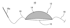
- FIG. 1 is a schematic configuration diagram (perspective view) of an intraocular lens fixing device according to an embodiment.
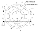
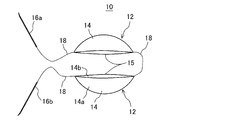
- FIG. 2 is a front view of a state in which the intraocular lens is fixed by the intraocular lens fixing device.
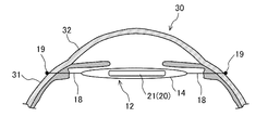
- FIG. 3 is a side view of a state in which the intraocular lens is fixed by the intraocular lens fixing device.
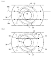
- FIG. 4 is a diagram for explaining a procedure for installing the first lens support portion with respect to a method of using the intraocular lens fixing device.
- FIG. 5 is a diagram for explaining a procedure for inserting a pair of haptics into a pair of haptic holding parts, regarding a method of using the intraocular lens fixing device.
- FIG. 1 is a schematic configuration diagram (perspective view) of an intraocular lens fixing device according to an embodiment.
- FIG. 2 is a front view of a state in which the intraocular lens is fixed by the intraocular lens fixing device.
- FIG. 3 is a side view of a state
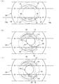
- FIG. 6 is a diagram for explaining a procedure until the position of the haptic holding unit is fixed with respect to the method of using the intraocular lens fixing device.
- FIG. 7 is a schematic configuration diagram (perspective view) of a lens support portion of an intraocular lens fixing device according to Modification 1.
- FIG. 8 is a schematic configuration diagram (perspective view) of a lens support portion of an intraocular lens fixing instrument according to Modification 2.
- FIG. 9 is a schematic configuration diagram (perspective view) of an intraocular lens fixing device according to Modification 3.
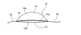
- FIG. 10 is a front view of a state in which the intraocular lens is fixed by the intraocular lens fixing device according to Modification 4.
- FIG. 7 is a schematic configuration diagram (perspective view) of a lens support portion of an intraocular lens fixing device according to Modification 1.
- FIG. 8 is a schematic configuration diagram (perspective view) of a lens support portion of an intraocular lens fixing instrument according to Modification 2.
- FIG. 9
- FIG. 11 is a schematic configuration diagram (perspective view) of a main part of a lens support portion of an intraocular lens fixing device according to Modification 5.
- FIG. 12 is a schematic configuration diagram (perspective view) of a main part of a lens support portion of an intraocular lens fixing device according to Modification 6.
- FIG. 13 is a diagram of a lens support portion according to Modification 6 as viewed from the side.
- the intraocular lens fixing device 10 is, for example, a device used to fix the intraocular lens 20 when the lens capsule is damaged or disappeared during lens reconstruction.
- the intraocular lens fixing device 10 can be applied to an intraocular lens 20 in which a plurality of haptics 22 are provided on the lens unit 21.
- a plurality of haptics 22 are provided on the lens unit 21.
- two haptics 22 protrude outward from the outer peripheral surface of the lens portion 21 (see FIG. 2).
- the two haptics 22 are provided point-symmetrically with respect to the center of the lens unit 21.
- the intraocular lens fixing device 10 includes a pair of lens support portions 12 each having a haptic holding portion 14. Each haptic holding portion 14 corresponds to a pair of haptics 22 of the intraocular lens 20. As shown in FIG. 2, the intraocular lens fixing device 10 is disposed in the eyeball 30 so that the entrances 15 of the pair of haptic holding portions 14 face each other. The intraocular lens fixing device 10 holds the pair of haptics 22 by the pair of haptic holding portions 14, thereby fixing the intraocular lens 20 in the eyeball 30. Note that FIG. 2 is a view seen from the front of the eyeball 30, but the inside of the eyeball 30 is indicated by a solid line. Further, each haptic holding part 14 is hatched.
- the pair of haptic holding portions 14 is arranged at a position slightly behind the iris in the eyeball 30, and the intraocular lens 20 is located inside the ciliary body. It is fixed at the position.
- the intraocular lens fixing device 10 will be described in detail.
- each lens supporting part 12 has two ends, one end connected to the haptic holding part 14 and the other end connected to the needle members 16a and 16b, as shown in FIG.
- a linear member 18 is provided.
- a thread tensile thread
- the needle member 16a of the one linear member 18 is a needle (straight needle for penetration) for introducing the linear member 18 and the haptic holding portion 14 into the eyeball 30, and a needle whose distal end portion is slightly bent (for example, A needle having a thickness of about 0.4 to 0.6 mm and a length of about 15 mm).
- the needle member 16b of the other linear member 18 is a needle used only for suturing, for example, a curved surgical (ophthalmic) suture needle (for example, a suture needle having a thickness of about 0.4 to 0.6 mm) ) Is used. Further, the two linear members 18 are stretched in the eyeball 30 and support the haptic holding part 14 introduced into the eyeball 30 in a floating state.
- a curved surgical (ophthalmic) suture needle for example, a suture needle having a thickness of about 0.4 to 0.6 mm
- the pair of haptic holding portions 14 are members for holding the haptic 22 of the intraocular lens 20 in place of the lens capsule and restraining the movement of the intraocular lens 20.
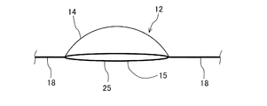
- Each haptic holding portion 14 is a bag-like member (specifically, a hammock-like member) in which an inlet 15 for inserting the haptic 22 is formed.
- the extending direction of the inner part serving as the inlet 15 is referred to as “length direction”
- the direction orthogonal to the extending direction is referred to as “width direction”.
- each haptic holding portion 14 is configured by a substantially linear inner portion serving as the inlet 15 and a curved outer portion that extends between both ends of the inner portion and expands outward in plan view.
- the inner portion may have a curved shape with a smaller curvature than the outer portion, for example.
- Each haptic holding portion 14 includes two sheets 14a and 14b having the same shape, and is formed by joining the outer peripheral portions of the two sheets 14a and 14b to each other except for the portion where the inlet 15 is formed. .
- each haptic holding portion 14 is formed in a crescent shape in plan view as shown in FIG.
- Each haptic holding portion 14 is formed by joining the outer peripheral portions of two crescent-shaped sheets 14a and 14b along an arc. The joining of the two sheets 14a and 14b is performed by, for example, heat welding, but other joining methods may be employed.
- Each haptic holding portion 14 has an outer peripheral portion other than a portion along the arc that is not joined, and the unjoined portion serves as an inlet 15.
- each haptic holding part 14 for example, the dimension in the length direction (the length of the inlet 15) is about 8 mm, and the dimension in the width direction is about 2 mm. Moreover, the diameter of the circular arc of each haptic holding
- a thin and flexible material (an example of a flexible material) is used for each sheet 14a and 14b in each haptic holding portion 14.
- the sheets 14a and 14b are made of resin.
- a 4 ⁇ m-thick propylene film is used for each of the sheets 14a and 14b.
- Each haptic holding portion 14 is formed to be able to pass through the needle hole 17 of the sclera 31 through which the needle member 16a passes.
- each haptic holding part 14 as shown in FIG. 1, the one end part of the linear member 18 is joined to the both ends of a length direction, respectively.
- the joining of the linear members 18 is performed by, for example, heat welding, but other joining methods may be employed.
- Each linear member 18 uses a thin surgical suture (for example, a 0.02-0.4 mm resin suture).
- a thin surgical suture for example, a 0.02-0.4 mm resin suture.
- polypropylene for example, 9-0 polypropylene
- polyester PGA
- nylon or the like.
- the other end of each linear member 18 is attached to the base of the needle members 16a and 16b.
- each haptic holding part 14 is formed with a position adjustment mark 13 (center mark) in the eyeball 30.
- the mark 13 is formed by a recess recessed inward in the sheet 14a (see a cross-sectional view in the ellipse in FIG. 1). The reason why the mark 13 is a recess is to prevent the mark 13 from hitting the iris.
- the mark 13 can be formed by a through hole (hole), a notch, a convex portion, or ink printing in addition to the concave portion. For the surgeon looking from the outside of the eyeball 30, the haptic holder 14 may be partially hidden behind the iris and difficult to see.
- the mark 13 is provided from the outside of the eyeball 30 so that the position of the haptic holding unit 14 in the eyeball 30 can be easily grasped.
- the mark 13 is arranged in a region inside the outer periphery of the haptic holding unit 14.
- the mark 13 is circular, for example, and is provided at the center (the center in the length direction) near the inlet 15 of the haptic holding unit 14.
- the mark 13 may be provided at another position, or the mark 13 may be omitted.
- the intraocular lens fixing device 10 inserts the intraocular lens 20 from the outside of the eyeball 30 when the intraocular lens 20 falls into the eyeball 30 (in the case of intraocular lens dislocation). It can be applied to any of the cases. Below, the case where the single piece multifocal IOL20 falls about the former is demonstrated to an example.
- one of the pair of lens support portions 12 is referred to as a first lens support portion 12 and the other is referred to as a second lens support portion 12.
- 4-6 is a view as seen from the front of the eyeball, but FIG. 4 shows the outside of the eyeball 30 by a solid line and the inside of the eyeball 30 by a wavy line, and FIG. 5-6 shows the outside of the eyeball 30. A broken line indicates the inside of the eyeball 30 with a solid line.
- the vitreous stem is excised and the tissue adhering to the intraocular lens 20 is excised in advance prior to the installation of the intraocular lens fixing instrument 10.
- the surgeon performs an operation of introducing the haptic holding unit 14 into the eyeball 30 with respect to the first lens support unit 12. Specifically, the surgeon passes through the needle member 16a with respect to the eyeball 30, as shown in FIG. The face threading method will be described.
- the operator passes the needle member 16a from the outside to the inside of the eyeball 30.
- the needle member 16a is inserted inward with respect to the welcome needle (not shown) passed from the outside to the inside of the eyeball 30 from a position symmetrical to the position through which the needle member 16a is passed.
- the welcome needle has a hollow structure. Then, the needle member 16a can be easily taken out from the inner side of the eyeball 30 from the desired position by pulling out the needle together with the needle member 16a. Needle holes 17 are formed in two places through the needle member 16a.
- the position through which the needle member 16a is passed is determined so that the haptic holding part 14 does not overlap the lens part 21 of the intraocular lens 20 after fixation.
- the needle member 16 a is 3 to 4 mm above the center of the eyeball 30 and is slightly outside the cornea 32 in the sclera 31 of the eyeball 30 on both the left and right sides (for example, the cornea 32 From 1.5 mm to 2 mm).
- the haptic holding portion 14 contracts (deforms) from the end portion and becomes narrower, so that the needle hole 17 (the left needle hole) 17) and pass through the needle hole 17.
- the operator pulls the needle member 16a to the right side until the haptic holding part 14 reaches approximately the middle of the eyeball 30 in the left-right direction.
- the first lens support portion 12 holds the haptic by the two linear members 18 spanned between the two needle holes 17 in the eyeball 30.
- the part 14 is provided in a suspended state. In this state, the operator puts water from the inlet 15 into the haptic holding part 14 to widen the haptic holding part 14. Note that a gel-like fluid containing hyaluronic acid or the like can be used instead of water.
- the surgeon performs an operation of introducing the haptic holding part 14 into the eyeball 30 with respect to the second lens support part 12.
- the second lens support unit 12 is provided on the first lens support unit 12 vertically symmetrically with respect to the center of the eyeball 30 in the same procedure as the first lens support unit 12.
- the second lens support portion 12 is formed between two needle holes 17 spanned between two needle holes 17 3 to 4 mm below the center of the eyeball 30 in the eyeball 30.
- the haptic holding part 14 is provided in a suspended state by the linear member 18.
- the second lens support portion 12 is preferably provided substantially parallel to the first lens support portion 12.
- the surgeon picks up the intraocular lens 20 that has fallen into the eyeball 30 with intraocular forceps (not shown) placed in the eyeball 30 through an incision formed in the sclera 31 of the eyeball 30.
- the surgeon inserts one haptic 22 into one haptic holding portion 14 from the entrance 15.
- the haptic holding part 14 is expanded by the haptic 22.
- the other haptic 22 is inserted from the inlet 15 into the other haptic holding portion 14.
- the other haptic holding part 14 is expanded.
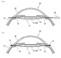
- FIG. 6A shows a state after the position adjustment of the intraocular lens 20.
- each haptic holding unit 14 is fixed, and the position of the intraocular lens 20 is held by each haptic holding unit 14. Furthermore, the operator sutures the incision used as the insertion port for the tweezers. This completes the lens reconstruction.
- the haptic holding part 14 holding the haptic 22 of the intraocular lens 20 is a bag-like member using a flexible material, and the needle hole through which the linear member 18 fixed to the haptic holding part 14 passes. 17 can be passed through and can be introduced into the eyeball 30 through the needle hole 17. Therefore, the haptic holding portion 14 can be easily introduced into the eyeball 30 by simply pulling the linear member 18 without forming an incision.
- each haptic holding part 14 can be adjusted by simply pulling the linear member 18.
- the surgeon looks at the position of the mark 13 so that each haptic holding part 14 is substantially the same as the lens capsule. Can be provided in position. Thereby, the intraocular lens 20 is held at a predetermined position.
- each haptic 22 of the intraocular lens 20 is softly held by the bag-like haptic holding portion 14. Each haptic 22 does not contact the intraocular tissue.
- the single piece multifocal IOL 20 has a thick haptic 22 and easily causes inflammation.
- the haptic 22 is made of a soft material (for example, a soft acrylic gel), and there is a possibility of tearing when the suture is directly tied. That is, the single piece multifocal IOL 20 is not suitable for either intraocular lens scleral fixation or intraocular lens ciliary groove stitching. These methods limit the types of intraocular lenses 20 that can be fixed.
- the installation position (depth) of the pair of haptic holding portions 14 can be determined in the front-rear direction according to the position through which the needle member 16 a passes through the sclera 31.
- the installation position of the holding portion of the intraocular lens is limited, and the depth of the intraocular lens is limited.
- the intraocular lens 20 can be fixed at an arbitrary depth.
- the intraocular lens 20 is inserted into the eyeball 30 from the outside, but also the intraocular lens 20 that has fallen into the eyeball 30 can be fixed without being extracted. That is, reduction of the intraocular lens 20 can be completed only by intraocular operation.
- a communication hole 24 is formed in each sheet 14 a, 14 b of each haptic holding portion 14 to allow communication between the inside of the bag and the outside of the bag.
- a plurality of communication holes 24 are provided.
- Each communication hole 24 is smaller than the cross section on the distal end side of the haptic 22 and is formed in a size that the haptic 22 cannot pass through.
- each haptic holding part 14 is not in a blind end structure due to the communication hole 24, so that bacteria hardly propagate in each haptic holding part 14.
- drugs such as antibiotics can be efficiently supplied into each haptic holding unit 14.
- the communication hole 24 may be formed at least at a position near the outer peripheral portion on the arc, or may be formed at a position near the inlet 15.
- each haptic holding part 14 is formed of a net-like and bag-like member.
- the mesh of each haptic holding portion 14 is smaller than the cross section on the tip side of the haptic 22 and has a size that the haptic 22 cannot pass through. According to this modification, bacteria hardly propagate in each haptic holding part 14.
- drugs such as antibiotics can be efficiently supplied into each haptic holding unit 14.
- the pair of haptic holding portions 14 are connected and integrated with each other by a linear member 18, as shown in FIG. That is, the two haptic holding portions 14 are provided on one thread-like body between the two needle members 16a and 16b.
- each haptic holding part 14 can be introduced into the eyeball 30 with each needle member 16a, 16b at the head. Thereby, scleral suture on one side becomes unnecessary.
- each haptic holding part 14 is formed of a member having a shape other than a bag shape. As shown in FIG. 10, each haptic holding portion 14 is composed of a plurality of ring-shaped portions that are hooked by the haptic 22. Specifically, each haptic holding portion 14 is an 8-shaped portion (a portion having flexibility) created by tying a suture. The haptic 22 is held by two annular portions.
- FIG. 10 is a view seen from the front of the eyeball 30, and the inside of the eyeball 30 is indicated by a solid line.
- the linear member 18 is attached along the edge of the inlet 15 of each haptic holding part 14.
- a narrow hole 15a is formed at the edge of the inlet 15 in each sheet 14a, 14b.
- the narrow hole 15a is formed, for example, by folding the sheets 14a and 14b.
- the linear member 18 is divided into two at one end portion of the haptic holding portion 14, and each is passed through the narrow holes 15 a of the separate sheets 14 a and 14 b and is joined at the other end portion of the haptic holding portion 14.
- the linear member 18 is fixed to the haptic holding part 14.
- the linear member 18 does not have to be provided along the inlet 15 of both sheets 14a and 14b, and may be provided and fixed along the inlet 15 of one of the sheets 14a. In this case, the linear member 18 is not separated between both ends of the haptic holding part 14. Further, the linear member 18 may be fixed along the entrance 15 of the sheet 14a without forming the narrow hole 15a in the sheet 14a.
- the linear member 18 is formed as a thin rod-shaped member such as a resin or a metal.
- an edge member 25 (for example, a resin member) that fixes the linear member 18 may be attached to the haptic holding portion 14.
- the edge member 25 is provided along the entire circumference along the inlet 15. Note that the linear member 18 (bar-shaped member) may be fixed to the haptic holding portion 14 without using the edge member 25. Further, when a thread-like member is used as the linear member 18 as in the above-described embodiment, the edge member 25 may be attached to the haptic holding portion 14.
- the heating tool 26 shown in FIG. The linear member 18 may be heated by using a heating end treatment for forming the stopper 19 shown in FIG. Thereby, the position of the haptic holding
- the heating end treatment is not limited to the case where the linear member 18 is a rod-like member, and can be applied to the case where the linear member 18 is a thread-like member.
- the needle members 16a and 16b are attached to the linear member 18 in the intraocular lens fixing instrument 10, but the product is not attached to the needle members 16a and 16b by an operator or the like. Needle members 16a and 16b may be retrofitted.
- the present invention can be applied to an intraocular lens fixing instrument used for fixing an intraocular lens.
Landscapes
- Health & Medical Sciences (AREA)
- Ophthalmology & Optometry (AREA)
- Cardiology (AREA)
- Oral & Maxillofacial Surgery (AREA)
- Transplantation (AREA)
- Engineering & Computer Science (AREA)
- Biomedical Technology (AREA)
- Heart & Thoracic Surgery (AREA)
- Vascular Medicine (AREA)
- Life Sciences & Earth Sciences (AREA)
- Animal Behavior & Ethology (AREA)
- General Health & Medical Sciences (AREA)
- Public Health (AREA)
- Veterinary Medicine (AREA)
- Prostheses (AREA)
Priority Applications (1)
| Application Number | Priority Date | Filing Date | Title |
|---|---|---|---|
| US17/079,139 US11850145B2 (en) | 2018-04-26 | 2020-10-23 | Intraocular lens fixing device |
Applications Claiming Priority (2)
| Application Number | Priority Date | Filing Date | Title |
|---|---|---|---|
| JP2018085885A JP7211714B2 (ja) | 2018-04-26 | 2018-04-26 | 眼内レンズ固定用器具 |
| JP2018-085885 | 2018-04-26 |
Related Child Applications (1)
| Application Number | Title | Priority Date | Filing Date |
|---|---|---|---|
| US17/079,139 Continuation US11850145B2 (en) | 2018-04-26 | 2020-10-23 | Intraocular lens fixing device |
Publications (1)
| Publication Number | Publication Date |
|---|---|
| WO2019208746A1 true WO2019208746A1 (ja) | 2019-10-31 |
Family
ID=68293653
Family Applications (1)
| Application Number | Title | Priority Date | Filing Date |
|---|---|---|---|
| PCT/JP2019/017825 Ceased WO2019208746A1 (ja) | 2018-04-26 | 2019-04-25 | 眼内レンズ固定用器具 |
Country Status (3)
| Country | Link |
|---|---|
| US (1) | US11850145B2 (enExample) |
| JP (1) | JP7211714B2 (enExample) |
| WO (1) | WO2019208746A1 (enExample) |
Cited By (2)
| Publication number | Priority date | Publication date | Assignee | Title |
|---|---|---|---|---|
| CN115697248A (zh) * | 2020-04-29 | 2023-02-03 | 长桥医疗有限公司 | 在眼睛内支撑和定位人工晶状体的装置和使用方法 |
| JP2024502442A (ja) * | 2021-01-13 | 2024-01-19 | ユネ キム,テ | 人工水晶体の支持構造物 |
Families Citing this family (1)
| Publication number | Priority date | Publication date | Assignee | Title |
|---|---|---|---|---|
| WO2025210530A1 (en) * | 2024-04-02 | 2025-10-09 | Rajam Trust | Intraocular lens device, intraocular lens system, and methods of using the same |
Citations (4)
| Publication number | Priority date | Publication date | Assignee | Title |
|---|---|---|---|---|
| JP2000229103A (ja) * | 1999-02-12 | 2000-08-22 | Takeshi Sugiura | 眼球の後房レンズ経毛様体強膜縫着における毛様溝パッド |
| JP2007029727A (ja) * | 2005-07-26 | 2007-02-08 | Visioncare Ophthalmic Technologies Inc | 眼内装置及び眼内装置支持部材 |
| US20120130389A1 (en) * | 2010-10-08 | 2012-05-24 | Prywes Arnold S | Apparatus and method for performing ocular surgery |
| WO2017134056A1 (en) * | 2016-02-02 | 2017-08-10 | Fundación Tekniker | Supporting device for the insertion of an intraocular lens, use of the device and intraocular lens insertion method |
Family Cites Families (7)
| Publication number | Priority date | Publication date | Assignee | Title |
|---|---|---|---|---|
| US4253199A (en) * | 1978-09-25 | 1981-03-03 | Surgical Design Corporation | Surgical method and apparatus for implants for the eye |
| JP2000245755A (ja) | 1999-03-02 | 2000-09-12 | Menicon Co Ltd | 眼内固定用補助具 |
| US6352542B1 (en) * | 2000-03-08 | 2002-03-05 | Michael E. Snyder | Intraocular lens with improved haptic and method of implanting same |
| AU2001259541A1 (en) * | 2000-05-15 | 2001-11-26 | Bausch & Lomb Incorporated | Injectable iris fixated intraocular lenses |
| DE102012016892A1 (de) * | 2012-08-24 | 2014-02-27 | Be Innovative Gmbh | Intraokularlinse, insbesondere Ziliarintraokularlinse |
| JP5816335B1 (ja) | 2014-05-28 | 2015-11-18 | 株式会社中京メディカル | 支持具 |
| AU2017345731B2 (en) * | 2016-10-21 | 2019-10-24 | Omega Ophthalmics Llc | Prosthetic capsular devices, systems, and methods |
-
2018
- 2018-04-26 JP JP2018085885A patent/JP7211714B2/ja active Active
-
2019
- 2019-04-25 WO PCT/JP2019/017825 patent/WO2019208746A1/ja not_active Ceased
-
2020
- 2020-10-23 US US17/079,139 patent/US11850145B2/en active Active
Patent Citations (4)
| Publication number | Priority date | Publication date | Assignee | Title |
|---|---|---|---|---|
| JP2000229103A (ja) * | 1999-02-12 | 2000-08-22 | Takeshi Sugiura | 眼球の後房レンズ経毛様体強膜縫着における毛様溝パッド |
| JP2007029727A (ja) * | 2005-07-26 | 2007-02-08 | Visioncare Ophthalmic Technologies Inc | 眼内装置及び眼内装置支持部材 |
| US20120130389A1 (en) * | 2010-10-08 | 2012-05-24 | Prywes Arnold S | Apparatus and method for performing ocular surgery |
| WO2017134056A1 (en) * | 2016-02-02 | 2017-08-10 | Fundación Tekniker | Supporting device for the insertion of an intraocular lens, use of the device and intraocular lens insertion method |
Cited By (3)
| Publication number | Priority date | Publication date | Assignee | Title |
|---|---|---|---|---|
| CN115697248A (zh) * | 2020-04-29 | 2023-02-03 | 长桥医疗有限公司 | 在眼睛内支撑和定位人工晶状体的装置和使用方法 |
| JP2024502442A (ja) * | 2021-01-13 | 2024-01-19 | ユネ キム,テ | 人工水晶体の支持構造物 |
| JP7518999B2 (ja) | 2021-01-13 | 2024-07-19 | ユネ キム,テ | 人工水晶体の支持構造物 |
Also Published As
| Publication number | Publication date |
|---|---|
| US11850145B2 (en) | 2023-12-26 |
| US20210038368A1 (en) | 2021-02-11 |
| JP2019187949A (ja) | 2019-10-31 |
| JP7211714B2 (ja) | 2023-01-24 |
Similar Documents
| Publication | Publication Date | Title |
|---|---|---|
| JP4370371B2 (ja) | 水晶体嚢保持器具 | |
| US4349027A (en) | Needle guide for implanting intra-ocular lens | |
| US6899733B2 (en) | Intraocular lens with improved haptic and method of implanting same | |
| JP3040101B1 (ja) | 眼球の後房レンズ経毛様体強膜縫着における毛様溝パッド | |
| US9132032B2 (en) | Apparatus and method for performing ocular surgery | |
| US10098624B2 (en) | Surgical apparatus and method of use thereof | |
| JP2016005521A (ja) | 眼内レンズ | |
| WO2019208746A1 (ja) | 眼内レンズ固定用器具 | |
| JP7518999B2 (ja) | 人工水晶体の支持構造物 | |
| RU2444339C1 (ru) | Способ репозиции интраокулярной линзы, дислоцированной вместе с капсульным мешком | |
| ES2965113T3 (es) | Lente intraocular que incluye porción de acoplamiento en la esclerótica | |
| RU2524195C1 (ru) | Способ репозиции интраокулярной линзы, дислоцированной вместе с фиброзно-измененным капсульным мешком | |
| RU2665182C1 (ru) | Способ имплантации и шовной фиксации S-образной интраокулярной линзы к радужке | |
| JP5398092B1 (ja) | 眼内レンズ | |
| KR20210028458A (ko) | 봉합사가 감겨진 지지부가 슬라이딩 가능하게 구비되는 인공수정체 고정장치 | |
| RU2440076C1 (ru) | Способ транссклеральной фиксации интраокулярной линзы при отсутствии капсульной поддержки | |
| JP2010012184A (ja) | 医療用縫合針付き縫合糸 | |
| KR102189890B1 (ko) | 봉합사의 고리를 묶는 밴딩부를 구비한 인공수정체 고정장치 | |
| US5988824A (en) | Anterior segment mirror and method of use for corneal transplant surgery | |
| JP2020005979A (ja) | 眼科用手術器具 | |
| RU2681108C1 (ru) | Способ подшивания интраокулярной линзы к радужной оболочке | |
| RU2440077C1 (ru) | Способ транссклеральной фиксации интраокулярной линзы при отсутствии капсульной поддержки | |
| US20130296876A1 (en) | Cystotome device | |
| JP6501608B2 (ja) | 眼内リング | |
| KR20230006121A (ko) | 인공수정체의 햅틱 고정장치 |
Legal Events
| Date | Code | Title | Description |
|---|---|---|---|
| 121 | Ep: the epo has been informed by wipo that ep was designated in this application |
Ref document number: 19793221 Country of ref document: EP Kind code of ref document: A1 |
|
| NENP | Non-entry into the national phase |
Ref country code: DE |
|
| 122 | Ep: pct application non-entry in european phase |
Ref document number: 19793221 Country of ref document: EP Kind code of ref document: A1 |