WO2019208025A1 - 映像表示装置 - Google Patents
映像表示装置 Download PDFInfo
- Publication number
- WO2019208025A1 WO2019208025A1 PCT/JP2019/011136 JP2019011136W WO2019208025A1 WO 2019208025 A1 WO2019208025 A1 WO 2019208025A1 JP 2019011136 W JP2019011136 W JP 2019011136W WO 2019208025 A1 WO2019208025 A1 WO 2019208025A1
- Authority
- WO
- WIPO (PCT)
- Prior art keywords
- video
- video display
- display device
- image
- horizontal direction
- Prior art date
- Legal status (The legal status is an assumption and is not a legal conclusion. Google has not performed a legal analysis and makes no representation as to the accuracy of the status listed.)
- Ceased
Links
Images








Classifications
-
- H—ELECTRICITY
- H04—ELECTRIC COMMUNICATION TECHNIQUE
- H04N—PICTORIAL COMMUNICATION, e.g. TELEVISION
- H04N13/00—Stereoscopic video systems; Multi-view video systems; Details thereof
- H04N13/30—Image reproducers
- H04N13/349—Multi-view displays for displaying three or more geometrical viewpoints without viewer tracking
- H04N13/351—Multi-view displays for displaying three or more geometrical viewpoints without viewer tracking for displaying simultaneously
-
- G—PHYSICS
- G02—OPTICS
- G02B—OPTICAL ELEMENTS, SYSTEMS OR APPARATUS
- G02B26/00—Optical devices or arrangements for the control of light using movable or deformable optical elements
- G02B26/08—Optical devices or arrangements for the control of light using movable or deformable optical elements for controlling the direction of light
-
- G—PHYSICS
- G02—OPTICS
- G02B—OPTICAL ELEMENTS, SYSTEMS OR APPARATUS
- G02B26/00—Optical devices or arrangements for the control of light using movable or deformable optical elements
- G02B26/08—Optical devices or arrangements for the control of light using movable or deformable optical elements for controlling the direction of light
- G02B26/0808—Optical devices or arrangements for the control of light using movable or deformable optical elements for controlling the direction of light by means of one or more diffracting elements
-
- G—PHYSICS
- G02—OPTICS
- G02B—OPTICAL ELEMENTS, SYSTEMS OR APPARATUS
- G02B26/00—Optical devices or arrangements for the control of light using movable or deformable optical elements
- G02B26/08—Optical devices or arrangements for the control of light using movable or deformable optical elements for controlling the direction of light
- G02B26/0816—Optical devices or arrangements for the control of light using movable or deformable optical elements for controlling the direction of light by means of one or more reflecting elements
-
- G—PHYSICS
- G02—OPTICS
- G02B—OPTICAL ELEMENTS, SYSTEMS OR APPARATUS
- G02B26/00—Optical devices or arrangements for the control of light using movable or deformable optical elements
- G02B26/08—Optical devices or arrangements for the control of light using movable or deformable optical elements for controlling the direction of light
- G02B26/0816—Optical devices or arrangements for the control of light using movable or deformable optical elements for controlling the direction of light by means of one or more reflecting elements
- G02B26/0833—Optical devices or arrangements for the control of light using movable or deformable optical elements for controlling the direction of light by means of one or more reflecting elements the reflecting element being a micromechanical device, e.g. a MEMS mirror, DMD
-
- G—PHYSICS
- G02—OPTICS
- G02B—OPTICAL ELEMENTS, SYSTEMS OR APPARATUS
- G02B30/00—Optical systems or apparatus for producing three-dimensional [3D] effects, e.g. stereoscopic images
- G02B30/50—Optical systems or apparatus for producing three-dimensional [3D] effects, e.g. stereoscopic images the image being built up from image elements distributed over a three-dimensional [3D] volume, e.g. voxels
- G02B30/56—Optical systems or apparatus for producing three-dimensional [3D] effects, e.g. stereoscopic images the image being built up from image elements distributed over a three-dimensional [3D] volume, e.g. voxels by projecting aerial or floating images
-
- G—PHYSICS
- G03—PHOTOGRAPHY; CINEMATOGRAPHY; ANALOGOUS TECHNIQUES USING WAVES OTHER THAN OPTICAL WAVES; ELECTROGRAPHY; HOLOGRAPHY
- G03B—APPARATUS OR ARRANGEMENTS FOR TAKING PHOTOGRAPHS OR FOR PROJECTING OR VIEWING THEM; APPARATUS OR ARRANGEMENTS EMPLOYING ANALOGOUS TECHNIQUES USING WAVES OTHER THAN OPTICAL WAVES; ACCESSORIES THEREFOR
- G03B35/00—Stereoscopic photography
- G03B35/18—Stereoscopic photography by simultaneous viewing
- G03B35/22—Stereoscopic photography by simultaneous viewing using single projector with stereoscopic-base-defining system
-
- H—ELECTRICITY
- H04—ELECTRIC COMMUNICATION TECHNIQUE
- H04N—PICTORIAL COMMUNICATION, e.g. TELEVISION
- H04N13/00—Stereoscopic video systems; Multi-view video systems; Details thereof
- H04N13/30—Image reproducers
- H04N13/363—Image reproducers using image projection screens
-
- H—ELECTRICITY
- H04—ELECTRIC COMMUNICATION TECHNIQUE
- H04N—PICTORIAL COMMUNICATION, e.g. TELEVISION
- H04N9/00—Details of colour television systems
- H04N9/12—Picture reproducers
- H04N9/31—Projection devices for colour picture display, e.g. using electronic spatial light modulators [ESLM]
- H04N9/3141—Constructional details thereof
- H04N9/315—Modulator illumination systems
- H04N9/3152—Modulator illumination systems for shaping the light beam
-
- H—ELECTRICITY
- H04—ELECTRIC COMMUNICATION TECHNIQUE
- H04N—PICTORIAL COMMUNICATION, e.g. TELEVISION
- H04N9/00—Details of colour television systems
- H04N9/12—Picture reproducers
- H04N9/31—Projection devices for colour picture display, e.g. using electronic spatial light modulators [ESLM]
- H04N9/3141—Constructional details thereof
- H04N9/315—Modulator illumination systems
- H04N9/3161—Modulator illumination systems using laser light sources
-
- H—ELECTRICITY
- H04—ELECTRIC COMMUNICATION TECHNIQUE
- H04N—PICTORIAL COMMUNICATION, e.g. TELEVISION
- H04N9/00—Details of colour television systems
- H04N9/12—Picture reproducers
- H04N9/31—Projection devices for colour picture display, e.g. using electronic spatial light modulators [ESLM]
- H04N9/3141—Constructional details thereof
- H04N9/315—Modulator illumination systems
- H04N9/3164—Modulator illumination systems using multiple light sources
-
- G—PHYSICS
- G03—PHOTOGRAPHY; CINEMATOGRAPHY; ANALOGOUS TECHNIQUES USING WAVES OTHER THAN OPTICAL WAVES; ELECTROGRAPHY; HOLOGRAPHY
- G03B—APPARATUS OR ARRANGEMENTS FOR TAKING PHOTOGRAPHS OR FOR PROJECTING OR VIEWING THEM; APPARATUS OR ARRANGEMENTS EMPLOYING ANALOGOUS TECHNIQUES USING WAVES OTHER THAN OPTICAL WAVES; ACCESSORIES THEREFOR
- G03B21/00—Projectors or projection-type viewers; Accessories therefor
- G03B21/54—Accessories
- G03B21/56—Projection screens
- G03B21/60—Projection screens characterised by the nature of the surface
- G03B21/606—Projection screens characterised by the nature of the surface for relief projection
Definitions
- This disclosure relates to a video display device that displays a plurality of viewpoint videos.
- a plurality of optical elements such as a plurality of light sources for a plurality of viewpoints emitting a plurality of laser beams and a lens for controlling a state of the plurality of laser beams may be required.
- the viewpoint image is displayed by deflecting with an array of small lenses, high positional accuracy of the lens and the laser is required in a wide range in order to display a desired image in the correct direction. For this reason, the entire apparatus is increased in size and cost.
- An image display apparatus includes at least one image source that emits a two-dimensional projection image, and a projection image from the image source is divided into a plurality of areas in at least a horizontal direction. Generate multiple area videos, and multiple area videos are directed toward each other so that multiple viewpoint videos can be displayed by overlapping them partially on a screen with anisotropic diffusion characteristics. And at least one image deflection unit that deflects and projects at different angles.
- the video deflection unit divides the projected video from the video source into at least a plurality of horizontal areas, and generates a plurality of area videos.
- the video deflecting unit is configured such that each of the plurality of area videos is directed toward the screen so that the plurality of area videos are partially overlapped on the screen having anisotropic diffusion characteristics to display a video from a plurality of viewpoints. Deflection projection at different angles.
- FIG. 1 is a top view schematically illustrating a configuration example of a video display device according to a first embodiment of the present disclosure. It is a top view which shows an example of the projection light from the video source in the video display apparatus which concerns on 1st Embodiment. It is a side view which shows roughly the example of 1 structure of the video display apparatus concerning 1st Embodiment. It is a side view which shows roughly the 1st modification of the video display apparatus concerning 1st Embodiment. It is a top view which shows roughly the 2nd modification of the video display apparatus concerning 1st Embodiment.
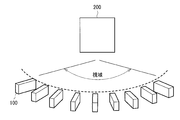
- FIG. 1 shows an outline of a video display device according to a comparative example.
- the video display apparatus includes a plurality of projectors 100 as video sources arranged in an array, and projects a video from each projector 100 toward a screen 200 having anisotropic diffusion characteristics to generate a stereoscopic video. indicate.
- one projector 100 emits an image for one viewpoint. For this reason, in order to display a plurality of viewpoint videos, as many video sources (projectors 100) as the number of viewpoints are required, which results in a large-scale apparatus as a whole.
- the base point of each video source is on the circumference, and even if each projector 100 is made small, it is difficult to reduce the size of the entire device.
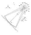
- FIG. 2 shows an example of the entire configuration of the video display device 1 viewed from the top surface direction.
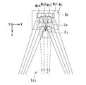
- FIG. 3 shows an example of a projection image (projection light) Lpj from the image source Pj in the image display device 1 as viewed from above.
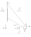
- FIG. 4 schematically shows a configuration example of the video display device 1 as viewed from the side.
- X indicates a horizontal direction
- Y indicates a vertical direction
- Z indicates a projection direction.
- the video display device 1 is configured such that a video source Pj that emits a two-dimensional projection video Lpj and a plurality of area videos Lpjn divided from the projection video Lpj are directed toward the screen 2. And an image deflection unit De that deflects and projects at different angles.
- Each of the plurality of area videos Lpjn corresponds to a viewpoint video with different viewpoints.
- the screen 2 is, for example, a flat screen having a transmissive or reflective anisotropic diffusion characteristic in which the light diffusion characteristic differs in the horizontal direction and the vertical direction.
- the screen 2 is, for example, an anisotropic diffusion plate.
- the screen 2 may be a diffractive element having anisotropic diffusion characteristics that have different light diffusion characteristics in the horizontal direction and the vertical direction.
- the diffractive element may be a holographic optical element (HOE).
- HOE holographic optical element
- the anisotropic diffusion characteristics of the screen 2 are desirably, for example, relatively narrow diffusion in the horizontal direction and relatively wide diffusion in the vertical direction. By narrowing the horizontal direction, it is possible to suppress unnecessary mixing of a plurality of viewpoint images projected from different angles.
- Z1 indicates an observation direction when the screen 2 is a transmission type.
- Z2 indicates an observation direction when the screen 2 is a reflection type. The same applies to the drawings shown in other embodiments described later.
- the image source Pj generates a two-dimensional projection image Lpj by emitting light rays two-dimensionally in time or space.
- the video source Pj is disposed between the screen 2 and the video deflection unit De.
- the video source Pj may be, for example, an LCOS (Liquid Crystal On On Silicon) type projector (reflective liquid crystal projector) that generates a projected video Lpj using a reflective liquid crystal element.
- the image source Pj generates a two-dimensional projection image Lpj by spatially emitting light in two dimensions.
- the video source Pj may be a projector that generates the projection video Lpj by a plurality of movable mirrors arranged two-dimensionally, for example.
- the video source Pj may be a DMD (Digital Micromirror Device) type MEMS (Micro ElectroMechanical System) projector.
- the image source Pj generates a two-dimensional projection image Lpj by spatially emitting light in two dimensions.
- the image source Pj may be a scanning projector that generates the projection image Lpj by a single scanning mirror.
- it may be a single mirror type MEMS projector that generates a two-dimensional projection image Lpj by two-dimensionally scanning laser light from one laser light source with a single scanning mirror.
- the video source Pj generates a two-dimensional projection video Lpj by emitting light in two dimensions in terms of time.
- the video deflection unit De divides the projected video Lpj from the video source Pj into at least a plurality of areas in the horizontal direction to generate a plurality of area videos Lpjn.
- the video deflection unit De is configured to display the plurality of area videos Lpjn at different angles from each other toward the screen 2 so that the plurality of area videos Lpjn are partially overlapped on the screen 2 to display a video from a plurality of viewpoints. Deflection projection. Thereby, for example, stereoscopic video display is performed.
- the image deflection unit De enlarges and deflects and projects the plurality of area images Lpjn at different angles toward the screen 2.
- the image deflection unit De includes a curved mirror array Mc having a plurality of curved mirrors Mcn arranged in the horizontal direction.
- Each of the plurality of curved mirrors Mcn has a curved surface shape (convex mirror) at least in the horizontal direction.
- FIG. 2 shows an example in which the curved mirror Mcn has a convex shape, the curved mirror Mcn may have a concave shape (concave mirror).
- the curved mirror array Mc of the video deflection unit De has four curved mirrors Mc1, Mc2, Mc3, and Mc4, and four area videos Lpj1, Lpj2, divided in a horizontal direction from one projection video Lpj.
- An example in which Lpj3 and Lpj4 are generated is shown.
- the number of area videos Lpjn generated from one projection video Lpj is not limited to four, but may be five or more, or two or three. It is only necessary to provide the number of curved mirrors Mcn constituting the curved mirror array Mc in accordance with the number of area videos Lpjn (viewpoint videos) to be generated.
- a projected image Lpj in the range of 41.5 ° is emitted from the image source Pj in the horizontal direction.
- four area images Lpj1, Lpj2, Lpj3, and Lpj4 obtained by dividing the projection image Lpj into 10 ° areas in the horizontal direction are incident on the image deflection unit De.
- the four area images Lpj1, Lpj2, Lpj3, and Lpj4 are incident on the four curved mirrors Mc1, Mc2, Mc3, and Mc4, respectively.
- the four curved mirrors Mc1, Mc2, Mc3, and Mc4 respectively deflect and project the four area images Lpj1, Lpj2, Lpj3, and Lpj4 toward the screen 2 by being enlarged and reflected at different angles.
- the curved mirrors Mc1, Mc2, Mc3, and Mc4 project the four area images Lpj1, Lpj2, Lpj3, and Lpj4 on the screen 2, for example, at different angles by 2 ° in the horizontal direction.
- four viewpoint videos whose viewpoint positions are shifted by 2 ° in the horizontal direction can be displayed.
- the video deflection unit De deflects and projects each of the plurality of area videos Lpjn so that the video center rays Vc of the plurality of area videos Lpjn coincide on the screen 2. Is desirable.
- the video source Pj and the video deflection unit De are disposed below the screen 2, for example. Thereby, a plurality of area videos Lpjn are launched and projected onto the screen 2 from below.
- the curved mirror array Mc in the image deflection unit De is disposed so as to be inclined with respect to the screen 2 at an angle corresponding to the launch angle. Further, each of the plurality of curved mirrors Mcn in the curved mirror array Mc has a planar shape in the vertical direction.
- the values of the division angle of the projection image Lpj and the deflection angles of the area images Lpj1, Lpj2, Lpj3, and Lpj4 on the screen 2 are examples, and are not limited to the above-described values.
- FIG. 5 shows an example of the overall configuration of the first modification of the video display device 1 as viewed from the side.
- the video display device 1A according to the first modification includes a video deflection unit Dea (curved mirror array Mc ′) instead of the video deflection unit De (curved mirror array Mc) in the video display device 1 shown in FIG. ing.
- FIG. 4 shows an example in which each of the plurality of curved mirrors Mcn in the curved mirror array Mc is planar in the vertical direction. However, like the curved mirror array Mc ′ shown in FIG. Each may be curved in the vertical direction. By making the plurality of curved mirrors Mcn into a curved shape in the vertical direction, the area image Lpjn can be enlarged and projected also in the vertical direction.
- FIG. 6 shows an example of the overall configuration of the second modification of the video display device 1 according to the first embodiment viewed from the top surface direction.
- a video display device 1B according to the second modification includes a plurality of video display units each including one video source Pj and one video deflection unit De in the video display device 1 illustrated in FIG. It has a configuration with. .., Pjn, and a plurality of video deflection units De1, De2,... Den.
- FIG. 6 shows a configuration example in which eight video sources Pj1, Pj2,... Pj8 and eight video deflection units De1, De2,.
- FIG. 6 shows a configuration example in which eight video sources Pj1, Pj2,... Pj8 and eight video deflection units De1, De2,.
- four viewpoint images whose viewpoint positions are shifted by 2 ° in the horizontal direction are displayed by a set of one image source Pj and one image deflection unit De
- 4 ⁇ 8. 32 viewpoint videos can be displayed.
- a plurality of area images Lpjn divided from the projected image Lpj from one image source Pj are deflected and projected at different angles toward the screen 2 at different angles. Since the viewpoint video display is performed, the multi-viewpoint video display can be performed in a small size and at a low cost.
- one projection image Lpj is divided into four area images Lpj1, Lpj2, Lpj3, and Lpj4. It is possible to project so that there are four virtual video sources Vpj (Vpj1, Vpj2, Vpj3, Vpj4). Thereby, the number of light sources (video sources) necessary for displaying videos from a plurality of viewpoints can be reduced as compared with the video display device according to the comparative example of FIG.
- the projection video Lpj from the video source Pj is folded back toward the screen 2 in the reverse direction by the video deflection unit De, so that the virtual video source Vpj with respect to the screen 2 is used. Can be positioned outside the image deflection unit De. Therefore, the size of the video display device including the screen 2 can be made smaller than when the video source Pj is actually arranged at the position of the virtual video source Vpj.
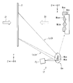
- FIG. 7 and 8 show a configuration example of the video display device 1C according to the second embodiment.
- FIG. 7 shows an example of the overall configuration of the video display device 1C viewed from the top surface direction.
- FIG. 8 schematically shows a configuration example of the video display device 1C as viewed from the side surface direction.
- the configuration example using the flat screen 2 is shown.
- the video display device 1C according to the second embodiment is a cylinder.
- the configuration uses a mold screen 2A.
- the cylindrical screen 2A is a substantially semi-cylindrical screen having a transmissive or reflective anisotropic diffusion characteristic in which the light diffusion characteristic differs in the horizontal direction and the vertical direction.
- the cylindrical screen 2A is, for example, an anisotropic diffusion plate.
- the cylindrical screen 2A may be a diffractive element having anisotropic diffusion characteristics that have different light diffusion characteristics in the horizontal direction and the vertical direction.
- the diffractive element may be a HOE.
- the anisotropic diffusion characteristics of the cylindrical screen 2A are desirably, for example, relatively narrow diffusion in the horizontal direction and relatively wide diffusion in the vertical direction. By narrowing the horizontal direction, it is possible to suppress unnecessary mixing of a plurality of viewpoint images projected from different angles.
- each of the plurality of area videos Lpjn is transmitted so that each video center ray Vc of the plurality of area videos Lpjn passes through the cylindrical axis C1 of the cylindrical screen 2A.
- Deflection projection is desirable.
- the image center rays Vc of the plurality of area images Lpjn are deflected and projected in a state of being slightly shifted at the same shift angle.
- the plurality of area images Lpjn are deflected and projected on the cylindrical surface of the cylindrical screen 2A so that each of the plurality of area images Lpjn is slightly shifted at the same shift angle.
- FIG. 9 schematically shows a first modification of the video display device 1C according to the second embodiment viewed from the side surface direction.
- the reflection mirror 3 is arranged on the upper side with respect to the cylindrical screen 2A, and the plurality of area images Lpjn from the image deflection unit De are once reflected by the upper reflection mirror 3, and then reflected. You may project on the cylindrical screen 2A toward the lower side from the mirror 3.
- the cylindrical screen 2A is a transmissive HOE
- the influence of the external light Lex from the screen surface opposite to the observation direction Z1 becomes a problem.
- the screen 2A is a HOE, as shown in FIG. 9, the plurality of area images Lpjn are once projected upward, reflected by the reflecting mirror 3, and then projected down to the screen 2A. Is less likely to enter and can be made less susceptible to the influence of external light Lex. Thereby, external light tolerance improves.
- FIG. 10 shows an example of the overall configuration of a second modification of the video display device 1C according to the second embodiment viewed from the top surface direction.
- the video display device 1D according to the second modification includes a plurality of video display units each including one video source Pj and one video deflection unit De in the video display device 1C illustrated in FIG. It has a configuration with. .., Pjn, and a plurality of video deflection units De1, De2,... Den.
- a plurality of area videos Lpjn are projected toward a complete cylindrical screen 2B having a projection plane of 360 °.
- a plurality of image sources Pj1, Pj2,... Pjn and a plurality of image deflection units De1, De2,... Den are arranged in a ring shape to project a plurality of area images Lpjn onto the 360 ° cylindrical screen 2B. As a result, a 360 ° multi-view video is obtained.
- the video deflection unit De in the video display devices according to the first and second embodiments may have the configuration shown in FIGS.
- FIG. 11 shows a first configuration example of the image deflection unit De viewed from the upper surface direction.
- the video deflection unit De may be a curved mirror array Mc having a plurality of curved mirrors Mcn arranged in the horizontal direction. Each of the plurality of curved mirrors Mcn has a curved surface shape at least in the horizontal direction.
- FIG. 11 shows an example in which the curved mirror Mcn has a convex shape (convex mirror) in the horizontal direction
- the curved mirror Mcn may have a concave shape (concave mirror) in the horizontal direction.
- the concave mirror is easier to increase the magnification.
- FIG. 11 illustrates an example in which the curved mirror array Mc of the image deflection unit De includes four curved mirrors Mc1, Mc2, Mc3, and Mc4.
- the number of the curved mirrors Mcn is not limited to four.
- the curved mirror array Mc may be five or more, or two or three. It is only necessary to provide the number of curved mirrors Mcn constituting the curved mirror array Mc in accordance with the number of area videos Lpjn (viewpoint videos) to be generated. Further, the curved mirror array Mc may have a planar shape (see FIG. 4) in the vertical direction, or may have a curved surface shape (see FIG. 5) in the vertical direction when enlarged projection is performed in the vertical direction.
- FIG. 12 shows a second configuration example of the image deflection unit De viewed from the upper surface direction.
- the image deflection unit De may include a curved mirror array Mc and a magnifying lens La.
- the configuration of the curved mirror array Mc may be substantially the same as in FIG.
- the magnifying lens La is disposed between the video source Pj and the curved mirror array Mc.
- the magnifying lens La has a light magnifying action at least in the horizontal direction.
- the projection image Lpj from the image source Pj may be enlarged by the magnifying lens La and then incident on the curved mirror array Mc.
- FIG. 13 shows a third configuration example of the video deflection unit De viewed from the top surface direction.
- the image deflection unit De may include a plane mirror array Mp and a magnifying lens La.
- the plane mirror array Mp has a plurality of plane mirrors Mpn arranged in the horizontal direction. Each of the plurality of plane mirrors Mpn has a planar shape at least in the horizontal direction.
- the plane mirror array Mp does not have an expansion action in the horizontal direction, but has a deflection action.
- the plurality of plane mirrors Mpn are respectively arranged at different angles so as to deflect and project the plurality of area videos Lpjn in different directions.
- the magnifying lens La plays a magnifying action in the horizontal direction of the image deflection unit De.
- the plane mirror array Mp of the video deflection unit De includes four plane mirrors Mp1, Mp2, Mp3, and Mp4.
- the number of the plurality of plane mirrors Mpn is limited to four. It may be five or more, or two or three.
- the number of the plurality of plane mirrors Mpn constituting the plane mirror array Mp may be provided by the number corresponding to the number of area videos Lpjn (viewpoint videos) to be generated.
- FIG. 14 shows a fourth configuration example of the image deflection unit De viewed from the top surface direction.
- the image deflection unit De may include a diffraction element array Ha having a plurality of diffraction regions Han arranged in the horizontal direction. Each of the plurality of diffraction regions Han has an expansion action and a deflection action at least in the horizontal direction.
- FIG. 14 shows an example in which the diffraction region Han of the image deflection unit De has four diffraction regions Ha1, Ha2, Ha3, Ha4, but the number of the plurality of diffraction regions Han is not limited to four, and five. It may be one or more, or two or three.
- the number of diffraction regions Han in the diffraction element array Ha may be provided by the number corresponding to the number of area images Lpjn (viewpoint images) to be generated.
- the diffractive element array Ha may have a configuration that does not have an expanding action in the vertical direction, or may have a configuration that has an expanding action in the vertical direction.
- the image deflection unit De may have a configuration including a magnifying lens La in addition to the diffraction element array Ha, as in the configuration example of FIG.
- FIG. 14 shows a configuration example in which the plurality of diffraction regions Han are reflective diffraction element arrays Ha having a reflection action, but a plurality of diffraction regions Han are transmission type diffraction element arrays having a transmission action. There may be.
- the projection direction of the plurality of area images Lpjn and the arrangement position of the screen 2 and the like are on the opposite side (upper side in FIG. 14) from the configuration examples thus far. .
- the video deflection unit De has a single-stage array configuration including one curved mirror array Mc and the like in the vertical direction, but a plurality of arrays are arranged in the vertical direction.
- a multi-stage array configuration may be used. By arranging a plurality of arrays in the vertical direction, the viewing area in the vertical direction can be expanded or the number of viewpoints can be increased in the vertical direction (see FIGS. 15 and 16). Also, the number of viewpoints can be increased in the horizontal direction, and the resolution in the horizontal direction can be improved (see FIG. 17).
- FIGS. 15 to 17 show a configuration example in which the curved mirror array Mc is arranged in two stages in the vertical direction, but an array configuration in which three or more stages are arranged in the vertical direction may be used.
- the plurality of curved mirrors Mcn in the curved mirror array Mc has a convex shape (convex mirror) in the horizontal direction
- the curved mirror Mcn may have a concave shape (concave mirror) in the horizontal direction.
- a plane mirror array Mp see FIG. 13
- a diffraction element array Ha see FIG. 14
- FIG. 5 a configuration example in which one curved mirror array Mc has a planar shape in the vertical direction is shown, but it may be curved in the vertical direction (see FIG. 5).
- FIG. 15 shows a configuration of the video display device 1E according to the first configuration example of the fourth embodiment viewed from the top surface direction and the side surface direction.
- FIG. 16 is an enlarged view of the video deflection unit De shown in FIG. 15 from the side surface direction.
- the video deflection unit De has two curved mirror arrays Mca and Mcb arranged at different positions in the vertical direction.
- the curved mirror array Mca has a plurality of curved mirrors Mcan arranged in the horizontal direction.
- the curved mirror array Mcb has a plurality of curved mirrors Mcab arranged in the horizontal direction.
- each of the plurality of curved mirrors Mcan in the curved mirror array Mca and each of the plurality of curved mirrors Mcbn in the curved mirror array Mcb are in the same position in the horizontal direction.
- the upper curved mirror Mcbn may be made larger than the lower curved mirror Mcn in consideration of the spread.
- the horizontal position is enlarged, and the arrangement of the lower curved mirror Mcn and the upper curved mirror Mcbn in the horizontal direction may be shifted by an enlarged ratio (the angular position with respect to the projection angle of view should be matched). Just fine).
- the two curved mirror arrays Mca and Mcb may be inclined and arranged at different inclination angles in the vertical direction.
- the projection angle (projection light) Lpja that is deflected and projected by the curved mirror array Mca and the projection image (projection light) Lpjb that is deflected and projected by the curved mirror array Mcb are made different, and the viewing area in the vertical direction is enlarged. can do.
- FIG. 17 shows a configuration of the video display device 1F according to the second configuration example of the fourth embodiment viewed from the top surface direction and the side surface direction.
- the video display device 1F according to the second configuration example includes two curved mirror arrays Mca in which the video deflection units De are arranged at different positions in the vertical direction. Mcb.
- the video display device 1F according to the second configuration example is different from the video display device 1E according to the first configuration example in the horizontal arrangement positions of the two curved mirror arrays Mca and Mcb.
- each of the plurality of curved mirrors M can in the curved mirror array Mca and each of the plurality of curved mirrors Mcbn in the curved mirror array Mcb.
- the vertical configuration of the video deflection unit De in the video display device 1F according to the second configuration example may be substantially the same as the first configuration example (FIG. 16).
- FIG. 18 shows a configuration example of the video source Pj in the video display apparatus according to the fifth embodiment viewed from the top surface direction.
- the video source Pj in the technology of the present disclosure can be configured by, for example, an LCOS projector, a DMD MEMS projector, or a single mirror MEMS projector.
- the image source Pj may be a scanning projector that generates a projection image Lpj by scanning a plurality of laser beams having different angles incident on a single scanning mirror.
- the image source Pj shown in FIG. 18 includes a MEMS mirror 11 that is a single scanning mirror, an end face laser array or VCSEL (Vertical Cavity Surface ⁇ ⁇ Emitting Laser) 12 that serves as a laser light source, and a condenser lens 13. Yes.
- MEMS mirror 11 that is a single scanning mirror
- VCSEL Very Cavity Surface ⁇ ⁇ Emitting Laser
- the VCSEL 12 is a surface emitting semiconductor laser that outputs a plurality of laser beams.
- the condensing lens 13 condenses the plurality of laser beams output from the VCSEL 12 toward the MEMS mirror 11 at different angles.
- the MEMS mirror 11 is, for example, a two-axis movable mirror that can tilt the mirror surface about two axes.
- a plurality of laser beams are incident on the MEMS mirror 11 that is a single scanning mirror at different angles, and the plurality of area images Lpjn are shared by the plurality of laser beams. It may be a scanning projector that scans and projects. As a result, the angle of view of the video source Pj is widened, so that the number of light sources (video sources) necessary for displaying a video from a plurality of viewpoints can be further reduced as compared with the video display device according to the comparative example of FIG. Can do.
- a plurality of laser beams are incident on a single scanning mirror at different angles and scanned to widen the angle while maintaining the laser modulation frequency. High resolution can be achieved.
- a projection image Lpj in the range of 83.5 ° in the horizontal direction is emitted from the image source Pj.
- four area images Lpj1, Lpj2, Lpj3, and Lpj4 obtained by dividing the projected image Lpj into areas of 20.5 ° in the horizontal direction are incident on the image deflection unit De.
- the MEMS mirror 11 is controlled so that one area image Lpjn is deflected and projected by one laser beam, but MEMS is deflected and projected by two or more area images Lpjn by one laser beam.
- the mirror 11 may be controlled.
- the case where the image deflection unit has an enlargement action in the horizontal direction is taken as an example.
- the image deflection unit may not have an enlargement action in the horizontal direction.
- the curved mirror Mcn may be formed in a planar shape in the horizontal direction, and the video deflection unit De may have only a deflection action in the horizontal direction.
- the diffraction region Han may be configured to have only a deflection operation without an expansion operation in the horizontal direction.
- this technique can also take the following structures.
- a plurality of viewpoint images are displayed by deflecting and projecting each of a plurality of area images divided from a projection image from an image source toward the screen at different angles. Therefore, it becomes possible to perform multi-view video display with small size and low cost.
- At least one image source for emitting a two-dimensional projection image The projected image from the image source is divided into at least a plurality of horizontal areas to generate a plurality of area images, and the plurality of area images are partially overlapped on a screen having anisotropic diffusion characteristics.
- An image display device comprising: at least one image deflecting unit that deflects and projects the plurality of area images toward the screen at angles different from each other so that a plurality of viewpoint images are displayed.
- the video display device according to (1) wherein the video deflection unit enlarges and deflects and projects the plurality of area videos toward the screen at different angles.
- the image deflection unit is Including at least one mirror array having a plurality of mirrors arranged in a horizontal direction; The video display device according to (1) or (2), wherein each of the plurality of mirrors has a curved surface shape or a planar shape in a horizontal direction.
- each of the plurality of mirrors has a curved surface shape in the horizontal direction and a planar shape or a curved surface shape in the vertical direction.
- the video deflection unit includes a plurality of the mirror arrays, The video display device according to (3) or (4), wherein the plurality of mirror arrays are arranged in a vertical direction.
- the video display device according to (5), wherein the plurality of mirror arrays of the plurality of mirror arrays at different positions in the vertical direction are different from each other in the horizontal direction.
- the image deflection unit is A mirror array having a plurality of mirrors arranged in a horizontal direction; The video display device according to (2), further including: a magnifying lens disposed between the video source and the mirror array. (9) The video display device according to (8), wherein each of the plurality of mirrors has a planar shape or a curved shape in a horizontal direction and has a planar shape or a curved shape in a vertical direction. (10) The image deflection unit is Including a diffractive element having a plurality of diffractive regions arranged in a horizontal direction, The image display device according to (1) or (2), wherein each of the plurality of diffraction regions has a deflecting action in at least a horizontal direction.
- the video display device according to any one of (1) to (10), wherein the video source is a liquid crystal projector that generates the projected video by a reflective liquid crystal element.
- the video source is a projector that generates the projection video by a plurality of movable mirrors arranged two-dimensionally.
- the video source is a scanning projector that generates the projection video by a single scanning mirror.
- the video source is a scanning projector that generates the projected video by scanning a plurality of laser beams having different angles incident on the single scanning mirror.
- the video display device according to any one of (1) to (14), further including a plurality of video display units each including one video source and one video deflection unit.
- the screen is a flat screen having a transmissive or reflective anisotropic diffusion characteristic in which a light diffusion characteristic differs in a horizontal direction and a vertical direction Display device.
- the screen is a cylindrical screen having a transmissive or reflective anisotropic diffusion characteristic in which a light diffusion characteristic differs in a horizontal direction and a vertical direction Display device.
- the video display device according to any one of (1) to (17), wherein the screen is an anisotropic diffusion plate having different light diffusion characteristics in a horizontal direction and a vertical direction.
- the screen is a diffraction element having anisotropic diffusion characteristics in which light diffusion characteristics are different in a horizontal direction and a vertical direction.
- the video source is disposed between the screen and the video deflection unit.
Landscapes
- Physics & Mathematics (AREA)
- Optics & Photonics (AREA)
- Engineering & Computer Science (AREA)
- Multimedia (AREA)
- Signal Processing (AREA)
- General Physics & Mathematics (AREA)
- Testing, Inspecting, Measuring Of Stereoscopic Televisions And Televisions (AREA)
- Transforming Electric Information Into Light Information (AREA)
- Projection Apparatus (AREA)
Priority Applications (2)
| Application Number | Priority Date | Filing Date | Title |
|---|---|---|---|
| JP2020516105A JP7226437B2 (ja) | 2018-04-25 | 2019-03-18 | 映像表示装置 |
| US17/046,917 US11973928B2 (en) | 2018-04-25 | 2019-03-18 | Image display device to display a plurality of viewpoint images |
Applications Claiming Priority (2)
| Application Number | Priority Date | Filing Date | Title |
|---|---|---|---|
| JP2018083669 | 2018-04-25 | ||
| JP2018-083669 | 2018-04-25 |
Publications (1)
| Publication Number | Publication Date |
|---|---|
| WO2019208025A1 true WO2019208025A1 (ja) | 2019-10-31 |
Family
ID=68293554
Family Applications (1)
| Application Number | Title | Priority Date | Filing Date |
|---|---|---|---|
| PCT/JP2019/011136 Ceased WO2019208025A1 (ja) | 2018-04-25 | 2019-03-18 | 映像表示装置 |
Country Status (3)
| Country | Link |
|---|---|
| US (1) | US11973928B2 (https=) |
| JP (1) | JP7226437B2 (https=) |
| WO (1) | WO2019208025A1 (https=) |
Cited By (2)
| Publication number | Priority date | Publication date | Assignee | Title |
|---|---|---|---|---|
| WO2022113614A1 (ja) * | 2020-11-27 | 2022-06-02 | ソニーグループ株式会社 | 表示装置 |
| US20240244175A1 (en) * | 2021-07-21 | 2024-07-18 | Sony Group Corporation | Stereoscopic display device |
Families Citing this family (1)
| Publication number | Priority date | Publication date | Assignee | Title |
|---|---|---|---|---|
| CN115185102B (zh) * | 2022-08-01 | 2024-03-26 | 清华大学 | 多级镜三维显示装置 |
Citations (7)
| Publication number | Priority date | Publication date | Assignee | Title |
|---|---|---|---|---|
| JP2006184770A (ja) * | 2004-12-28 | 2006-07-13 | Fuji Photo Film Co Ltd | カラー画像表示装置 |
| JP2008219618A (ja) * | 2007-03-06 | 2008-09-18 | Denso Corp | 映像表示装置 |
| JP2013210590A (ja) * | 2012-03-30 | 2013-10-10 | National Institute Of Information & Communication Technology | 立体ディスプレイ |
| CN103713463A (zh) * | 2012-10-09 | 2014-04-09 | 耿征 | 真三维图像显示系统及显示方法 |
| US20150241843A1 (en) * | 2014-02-21 | 2015-08-27 | Korea Advanced Institute Of Science And Technology | Apparatus and Method for Forming 3-Dimensional Holographic Image Using Scattering Layer |
| JP2016142991A (ja) * | 2015-02-04 | 2016-08-08 | 株式会社リコー | 画像処理システム、情報処理装置、画像処理方法、及びプログラム |
| WO2017029365A1 (de) * | 2015-08-19 | 2017-02-23 | Fraunhofer-Gesellschaft zur Förderung der angewandten Forschung e.V. | Multiaperturabbildungsvorrichtung mit einer reflektierende facetten aufweisenden strahlumlenkvorrichtung |
Family Cites Families (7)
| Publication number | Priority date | Publication date | Assignee | Title |
|---|---|---|---|---|
| US6932476B2 (en) * | 2002-09-20 | 2005-08-23 | Canon Kabushiki Kaisha | Stereoscopic image display apparatus and stereoscopic image display system |
| DE602005023300D1 (de) * | 2004-05-26 | 2010-10-14 | Tibor Balogh | Verfahren und vorrichtung zur erzeugung von 3d-bildern |
| JP4241776B2 (ja) * | 2006-07-21 | 2009-03-18 | セイコーエプソン株式会社 | 画像表示装置 |
| HU0900478D0 (en) * | 2009-07-31 | 2009-09-28 | Holografika Hologrameloeallito | Method and apparatus for displaying 3d images |
| KR20140050129A (ko) * | 2012-10-17 | 2014-04-29 | 삼성전자주식회사 | 다시점 및 초다시점 영상을 디스플레이하는 장치 및 방법 |
| JP6819237B2 (ja) | 2016-11-21 | 2021-01-27 | 株式会社リコー | 給送装置および画像形成装置 |
| US10869022B2 (en) * | 2018-03-21 | 2020-12-15 | City University Of Hong Kong | Autostereoscopic multi-view display system and related apparatus |
-
2019
- 2019-03-18 JP JP2020516105A patent/JP7226437B2/ja active Active
- 2019-03-18 US US17/046,917 patent/US11973928B2/en active Active
- 2019-03-18 WO PCT/JP2019/011136 patent/WO2019208025A1/ja not_active Ceased
Patent Citations (7)
| Publication number | Priority date | Publication date | Assignee | Title |
|---|---|---|---|---|
| JP2006184770A (ja) * | 2004-12-28 | 2006-07-13 | Fuji Photo Film Co Ltd | カラー画像表示装置 |
| JP2008219618A (ja) * | 2007-03-06 | 2008-09-18 | Denso Corp | 映像表示装置 |
| JP2013210590A (ja) * | 2012-03-30 | 2013-10-10 | National Institute Of Information & Communication Technology | 立体ディスプレイ |
| CN103713463A (zh) * | 2012-10-09 | 2014-04-09 | 耿征 | 真三维图像显示系统及显示方法 |
| US20150241843A1 (en) * | 2014-02-21 | 2015-08-27 | Korea Advanced Institute Of Science And Technology | Apparatus and Method for Forming 3-Dimensional Holographic Image Using Scattering Layer |
| JP2016142991A (ja) * | 2015-02-04 | 2016-08-08 | 株式会社リコー | 画像処理システム、情報処理装置、画像処理方法、及びプログラム |
| WO2017029365A1 (de) * | 2015-08-19 | 2017-02-23 | Fraunhofer-Gesellschaft zur Förderung der angewandten Forschung e.V. | Multiaperturabbildungsvorrichtung mit einer reflektierende facetten aufweisenden strahlumlenkvorrichtung |
Cited By (2)
| Publication number | Priority date | Publication date | Assignee | Title |
|---|---|---|---|---|
| WO2022113614A1 (ja) * | 2020-11-27 | 2022-06-02 | ソニーグループ株式会社 | 表示装置 |
| US20240244175A1 (en) * | 2021-07-21 | 2024-07-18 | Sony Group Corporation | Stereoscopic display device |
Also Published As
| Publication number | Publication date |
|---|---|
| US11973928B2 (en) | 2024-04-30 |
| JP7226437B2 (ja) | 2023-02-21 |
| US20210160465A1 (en) | 2021-05-27 |
| JPWO2019208025A1 (ja) | 2021-05-13 |
Similar Documents
| Publication | Publication Date | Title |
|---|---|---|
| CN105579883B (zh) | 图像投影仪和光学组件 | |
| JP6207850B2 (ja) | 虚像表示装置 | |
| JP6212683B2 (ja) | 立体画像投影装置、立体画像投影方法、及び立体画像投影システム | |
| JP2017167181A (ja) | 表示装置および導光装置 | |
| WO2001005146A1 (en) | Compact rear projection system | |
| JPWO2016052359A1 (ja) | 画像光投影用スクリーンおよび表示システム | |
| JP2008224760A (ja) | プロジェクタ | |
| CA2535691A1 (en) | Wide angle scanner for panoramic display | |
| JP7226437B2 (ja) | 映像表示装置 | |
| JP2016507075A (ja) | スペックルを減少するための方法 | |
| CN111929914A (zh) | 一种单向匀光扩束屏及三维显示装置 | |
| US7204593B2 (en) | 3-D image display unit | |
| JP2016018113A (ja) | ヘッドマウントディスプレイ | |
| CN105388613A (zh) | 图像产生设备、平视显示器和用于产生图像的方法 | |
| CN113741030B (zh) | 光机模块 | |
| US20150070659A1 (en) | Method for reducing speckles and a light source used in said method | |
| JP6402854B2 (ja) | 透過型スクリーン及びそれを用いたヘッドアップディスプレイ装置 | |
| WO2020189411A1 (ja) | 画像表示装置 | |
| US20130009945A1 (en) | Electronic Display Method and Apparatus | |
| JP6637658B2 (ja) | ホログラム表示装置 | |
| JP2017142284A (ja) | 表示装置及びヘッドアップディスプレイ | |
| KR20230126531A (ko) | 다면 투사용 빔 프로젝터 | |
| US11435595B2 (en) | Image display apparatus | |
| JP2018087900A (ja) | 画像表示装置 | |
| JP2022115498A (ja) | 3次元映像表示装置 |
Legal Events
| Date | Code | Title | Description |
|---|---|---|---|
| 121 | Ep: the epo has been informed by wipo that ep was designated in this application |
Ref document number: 19793448 Country of ref document: EP Kind code of ref document: A1 |
|
| ENP | Entry into the national phase |
Ref document number: 2020516105 Country of ref document: JP Kind code of ref document: A |
|
| NENP | Non-entry into the national phase |
Ref country code: DE |
|
| 122 | Ep: pct application non-entry in european phase |
Ref document number: 19793448 Country of ref document: EP Kind code of ref document: A1 |