WO2019207761A1 - Compresseur et son procédé de fabrication - Google Patents
Compresseur et son procédé de fabrication Download PDFInfo
- Publication number
- WO2019207761A1 WO2019207761A1 PCT/JP2018/017176 JP2018017176W WO2019207761A1 WO 2019207761 A1 WO2019207761 A1 WO 2019207761A1 JP 2018017176 W JP2018017176 W JP 2018017176W WO 2019207761 A1 WO2019207761 A1 WO 2019207761A1
- Authority
- WO
- WIPO (PCT)
- Prior art keywords
- casing
- head
- axial direction
- peripheral surface
- ring
- Prior art date
Links
Images


Classifications
-
- F—MECHANICAL ENGINEERING; LIGHTING; HEATING; WEAPONS; BLASTING
- F04—POSITIVE - DISPLACEMENT MACHINES FOR LIQUIDS; PUMPS FOR LIQUIDS OR ELASTIC FLUIDS
- F04D—NON-POSITIVE-DISPLACEMENT PUMPS
- F04D29/00—Details, component parts, or accessories
- F04D29/08—Sealings
- F04D29/083—Sealings especially adapted for elastic fluid pumps
-
- F—MECHANICAL ENGINEERING; LIGHTING; HEATING; WEAPONS; BLASTING
- F04—POSITIVE - DISPLACEMENT MACHINES FOR LIQUIDS; PUMPS FOR LIQUIDS OR ELASTIC FLUIDS
- F04D—NON-POSITIVE-DISPLACEMENT PUMPS
- F04D17/00—Radial-flow pumps, e.g. centrifugal pumps; Helico-centrifugal pumps
- F04D17/08—Centrifugal pumps
- F04D17/10—Centrifugal pumps for compressing or evacuating
- F04D17/12—Multi-stage pumps
- F04D17/122—Multi-stage pumps the individual rotor discs being, one for each stage, on a common shaft and axially spaced, e.g. conventional centrifugal multi- stage compressors
- F04D17/125—Multi-stage pumps the individual rotor discs being, one for each stage, on a common shaft and axially spaced, e.g. conventional centrifugal multi- stage compressors the casing being vertically split
-
- F—MECHANICAL ENGINEERING; LIGHTING; HEATING; WEAPONS; BLASTING
- F04—POSITIVE - DISPLACEMENT MACHINES FOR LIQUIDS; PUMPS FOR LIQUIDS OR ELASTIC FLUIDS
- F04D—NON-POSITIVE-DISPLACEMENT PUMPS
- F04D29/00—Details, component parts, or accessories
- F04D29/08—Sealings
- F04D29/16—Sealings between pressure and suction sides
- F04D29/161—Sealings between pressure and suction sides especially adapted for elastic fluid pumps
- F04D29/162—Sealings between pressure and suction sides especially adapted for elastic fluid pumps of a centrifugal flow wheel
-
- F—MECHANICAL ENGINEERING; LIGHTING; HEATING; WEAPONS; BLASTING
- F04—POSITIVE - DISPLACEMENT MACHINES FOR LIQUIDS; PUMPS FOR LIQUIDS OR ELASTIC FLUIDS
- F04D—NON-POSITIVE-DISPLACEMENT PUMPS
- F04D29/00—Details, component parts, or accessories
- F04D29/40—Casings; Connections of working fluid
- F04D29/42—Casings; Connections of working fluid for radial or helico-centrifugal pumps
- F04D29/4206—Casings; Connections of working fluid for radial or helico-centrifugal pumps especially adapted for elastic fluid pumps
-
- F—MECHANICAL ENGINEERING; LIGHTING; HEATING; WEAPONS; BLASTING
- F04—POSITIVE - DISPLACEMENT MACHINES FOR LIQUIDS; PUMPS FOR LIQUIDS OR ELASTIC FLUIDS
- F04D—NON-POSITIVE-DISPLACEMENT PUMPS
- F04D29/00—Details, component parts, or accessories
- F04D29/60—Mounting; Assembling; Disassembling
- F04D29/62—Mounting; Assembling; Disassembling of radial or helico-centrifugal pumps
- F04D29/622—Adjusting the clearances between rotary and stationary parts
-
- F—MECHANICAL ENGINEERING; LIGHTING; HEATING; WEAPONS; BLASTING
- F04—POSITIVE - DISPLACEMENT MACHINES FOR LIQUIDS; PUMPS FOR LIQUIDS OR ELASTIC FLUIDS
- F04D—NON-POSITIVE-DISPLACEMENT PUMPS
- F04D29/00—Details, component parts, or accessories
- F04D29/60—Mounting; Assembling; Disassembling
- F04D29/62—Mounting; Assembling; Disassembling of radial or helico-centrifugal pumps
- F04D29/624—Mounting; Assembling; Disassembling of radial or helico-centrifugal pumps especially adapted for elastic fluid pumps
Definitions
- the present invention relates to a compressor and a method for manufacturing the compressor.
- the centrifugal compressor passes gas through a rotating impeller and compresses the gas using centrifugal force generated at that time.
- a centrifugal compressor a multistage centrifugal compressor that includes a plurality of impellers and compresses a gas stepwise is known.
- Such a centrifugal compressor has a structure including a casing that can be divided vertically by a dividing surface that extends in the horizontal direction.
- the casing is configured by placing the upper half casing on the lower half casing installed on the floor and fastening it with bolts or the like.
- a rotor is disposed so as to penetrate the casing. The rotor is rotatable with respect to the casing.
- Patent Document 1 describes a multistage centrifugal compressor including a diaphragm formed into a ring shape by combining a semi-annular upper half diaphragm and a lower half diaphragm.
- the combined diaphragms are fixed in a state of being adjacent to each other in the axial direction inside a casing that can be divided vertically.
- a ring member that can be divided vertically is provided on the outer peripheral surface of the diaphragm. By this ring member, the axial position of the diaphragm with respect to the casing is regulated.
- Patent Document 2 also describes a compressor having a casing that can be divided into upper and lower parts.
- an internal unit in which a diaphragm and a rotor are integrally formed is disposed in a casing that can be divided vertically.
- the internal unit is provided with a pair of heads arranged so as to sandwich a plurality of diaphragms on both sides in the axial direction of the rotor and sealing the openings at both ends of the casing.
- the casing has a plurality of fitting recesses. The position of the diaphragm in the axial direction relative to the casing is regulated by fitting a plurality of fitting projections formed on the diaphragm and the head into the fitting recess.
- a structure is provided between the inner peripheral surface of the casing and the outer peripheral surfaces of the plurality of diaphragms to restrict the position in the axial direction of the diaphragm relative to the casing.
- the present invention provides a compressor capable of reducing leakage between the inner peripheral surface of the casing and the outer peripheral surface of the diaphragm, and a method for manufacturing the compressor.
- the compressor according to the first aspect of the present invention includes an upper half casing having an upper half casing dividing surface which is a horizontal surface facing downward in the vertical direction, and a lower half casing dividing surface capable of contacting the upper half casing dividing surface.
- a cylindrical casing having both ends opened, an impeller rotatable around an axis, and a flow in which the impeller is housed and fluid is introduced into the flow path of the impeller
- a communication gap seal portion that seals the communication gap extending in the axial direction between, and a restriction portion that is provided in at least one of the casing and the head and restricts the axial position of the head relative to the casing; .
- the communication gap is formed between the outer peripheral surface of the diaphragm and the inner peripheral surface of the casing, thereby preventing interference and the like when assembling the casing and the bundle having the upper and lower divided structure, Assemblability can be improved. Furthermore, since the communication gap is sealed, it is possible to prevent the high-pressure fluid supplied to the discharge port from leaking from the suction port through the communication gap.
- the restriction portion includes a fitting recess formed on one of the outer peripheral surface of the head and the inner peripheral surface of the casing, the outer peripheral surface of the head, You may have the fitting convex part which is formed in the other inner peripheral surface of the said casing, and fits with the said fitting recessed part.
- the position of the head in the axial direction with respect to the casing can be regulated with a simple structure.
- the restricting portion is not directly formed as a separate member but directly as a part of the casing and the head. Therefore, the number of parts to be assembled is reduced, and adjustment when assembling the casing and the bundle is facilitated.
- the restricting portion is provided on the outer side in the axial direction that is opposite to the side on which the diaphragm is disposed with respect to the head in the casing. And may be in contact with a surface of the head facing outward in the axial direction.
- the position of the head in the axial direction with respect to the casing can be regulated at a portion located outside the compressor. Therefore, it can be confirmed that the position of the bundle with respect to the casing is regulated at a position that can be viewed from the outside.
- the casing is a casing main body that covers an outer peripheral surface of the bundle, and the restriction portion, and protrudes radially inward from the casing main body. And a projecting portion that is in contact with an end face of the head facing outward in the axial direction.
- the protruding portion is located outside the compressor, so it is difficult to be limited in space. Therefore, even if the thrust force generated in the bundle is large depending on the type of fluid to be compressed, the protrusion can be enlarged in accordance with the force generated in the bundle. Thereby, the position of the bundle with respect to the casing can be stably held.
- the inner periphery of the casing is arranged such that the restricting portion is located at least partially outside the axial direction with respect to the head.
- a regulating housing recess recessed from the surface, a first regulating member housed in the regulating housing recess and in contact with a surface facing the outside in the axial direction of the head, and the outside in the axial direction than the first regulating member And a surface facing the inner side in the axial direction that is the side where the diaphragm is disposed in the restriction receiving recess, and a surface facing the outer side in the axial direction of the first ring member; You may have the 2nd control member which is contacting.
- the first regulating member and the second regulating member can be attached from the outside after assembling the bundle and the casing. Therefore, when installing a bundle in a lower half casing or installing an upper half casing on a bundle, it is not necessary to finely adjust the axial positions of the bundle, the lower half casing, and the upper half casing. Thereby, assembly property can be improved further.
- the communication gap seal portion is an O-ring, and the communication gap seal portion is disposed on an outer peripheral surface of the diaphragm.
- a gap seal mounting groove is formed, and the gap seal mounting groove is formed so as to become deeper in the circumferential direction from at least one of the upper apex in the vertical direction and the lower apex in the vertical direction of the diaphragm. It may be.
- the horizontal ends of the diaphragm are close to the split surface of the casing. For this reason, if the protruding amount of the communication gap seal portion increases at both ends in the horizontal direction, the communication gap seal portion is sandwiched between the dividing surfaces or rubbed against the casing edge when the upper half casing is attached to the lower half casing. May cause damage.
- the gap seal mounting groove is formed so as to become deeper in the circumferential direction. For this reason, the gap clearance seal portion fitted in the clearance seal mounting groove has a smaller amount of protrusion from the outer peripheral surface of the diaphragm as it goes in the circumferential direction from the upper apex in the vertical direction or the lower apex in the vertical direction. Thereby, damage to the communication gap seal portion when the upper half casing is attached to the lower half casing can be reduced.
- the gap seal mounting groove is 90 degrees in the circumferential direction of the diaphragm with respect to the upper vertex in the vertical direction and the lower vertex in the vertical direction in the diaphragm. You may form so that it may become deepest in the position of the both ends of a different horizontal direction.
- the protruding amount of the communication gap seal portion is the smallest at both ends in the horizontal direction. Therefore, it is possible to more effectively reduce damage to the communication gap seal portion when the upper half casing is attached to the lower half casing.
- the discharge-side head which is the head disposed at a position close to the discharge port, and the diaphragm are fixed.
- a fastening portion wherein the fastening portion is formed in a surface facing the axial direction in one of the discharge side head and the diaphragm, and has a fixed hole having an internal thread; and the other of the discharge side head and the diaphragm
- the fastening through hole formed at a position overlapping the to-be-fixed hole when viewed from the axial direction, and an external thread on the outer peripheral surface, and the to-be-fixed hole inserted through the fastening through-hole.
- a bolt member having a head portion formed at an end portion of the shaft portion, a head portion of the bolt member, and a surface on which the fastening through hole is formed.
- the compressor in any one of the first aspect to the eighth aspect, includes a head seal portion that seals between the head and the casing, and the head seal portion includes the head Alternatively, an annular ring insertion portion that is movable in the axial direction from the outside of the casing and is inserted between the outer peripheral surface of the head and the inner peripheral surface of the casing, and the inner peripheral surface of the ring insertion portion.
- You may have an inner ring seal part which seals between the outer peripheral surfaces of the said head, and an outer ring seal part which seals between the outer peripheral surface of the said ring insertion part, and the inner peripheral surface of the said casing.
- the ring insertion portion is attached to and detached from the outside in the axial direction, which is opposite to the side on which the diaphragm is disposed with respect to the head or the casing. It may be possible.
- the outer peripheral surface of the ring insertion portion and the inner side of the casing at a position shifted in the axial direction with respect to the outer ring seal portion.
- An insertion gap enlarged diameter portion that widens the gap between the peripheral surface and the peripheral surface may be formed.
- a gap between the outer peripheral surface of the ring insertion groove and the inner peripheral surface of the casing is increased.
- damage caused by rubbing the inner ring seal portion or the outer ring seal portion against the inner peripheral surface of the casing can be reduced.
- a discharge-side head that is the head disposed at a position close to the discharge port with respect to the casing.
- a movable holding part capable of relatively moving in the axial direction and holding the position of the discharge side head at an arbitrary position in the axial direction, and the movement holding part moves the discharge side head from the diaphragm.
- the position of the discharge-side head is held at a position where the discharge-side head cannot move toward the outer side in the axial direction which is the farthest position and opposite to the side where the diaphragm is disposed. Also good.
- the discharge-side head can be moved via the movement holding unit. Therefore, the position in the axial direction of the discharge-side head relative to the casing can be determined from the outside of the compressor. This eliminates the need to finely adjust the axial position of the bundle and casing when assembling the casing and bundle. Thereby, assembly property can be improved further.
- the fixed member fixed to the discharge-side head is formed in the movement holding portion, the fixed member communication hole communicating in the axial direction is formed.
- a shaft member that is provided with a male screw on the outer peripheral surface and is inserted into the fixed member communication hole, and one end of which is fixed to the casing, and a female screw is provided inside to allow the shaft member to pass through the inside.
- a second nut that is movable relative to the shaft member in the inserted state and is disposed on the side opposite to the first nut with respect to the fixed member may be included.
- the discharge-side head can be moved only by rotating the first nut and the second nut relative to the shaft member so as to move in the axial direction. for that reason.
- the discharge-side head can be moved with a simple structure without using a complicated device.
- a wire insertion portion capable of inserting a wire is formed at the lower end in the vertical direction of the head. Good.
- the bundle can be moved in a stable state.
- the compressor manufacturing method includes an upper half casing having an upper half casing dividing surface which is a horizontal surface facing downward in the vertical direction, and a lower half capable of contacting the upper half casing dividing surface.
- a plurality of diaphragms formed with flow paths for introducing the flow paths into the impeller flow paths, and annular heads that are fixed to both sides of the plurality of diaphragms in the axial direction in which the axis extends to close the openings of the casing,
- the bundle is lowered from above in the vertical direction, and a suction port through which fluid flows and a discharge port through which fluid is discharged communicate between
- the gap extending in the axial direction is formed between the outer peripheral surface of the diaphragm and the inner peripheral surface of the upper half casing so as to communicate the suction port and the discharge port.
- the communication gap seal portion is in contact with the inner peripheral surface of the lower half casing in a state where the axial position of the head is regulated with respect to the lower half casing.
- the communication gap seal portion is disposed in the upper half casing in a state where the axial position of the head is regulated with respect to the upper half casing.
- the said upper half casing is arrange
- an annular ring insertion portion insertable between the outer peripheral surface of the head and the inner peripheral surface of the casing, and the ring insertion
- An inner ring seal portion capable of sealing between the inner peripheral surface of the portion and the outer peripheral surface of the head
- an outer ring seal portion capable of sealing between the outer peripheral surface of the ring insertion portion and the inner peripheral surface of the casing.
- a head seal portion preparation step for preparing a head seal portion for sealing between the head and the casing, and the upper half casing arrangement step, and the ring insertion portion from the outside of the head or the casing.
- a head seal portion moving step of contacting said outer ring seal portion and the inner peripheral surface of the serial casing may further comprise a.
- the head seal portion moving step is opposite to the side on which the diaphragm is disposed with respect to the head or the casing.
- the ring insertion portion may be inserted between the outer peripheral surface of the head and the inner peripheral surface of the casing from the outside in the axial direction.
- the head disposed at a position close to the discharge port with respect to the casing.
- the fixing release step for releasing the fixation between the discharge side head and the diaphragm
- the discharge side head being connected to the diaphragm Up to a position where the discharge-side head cannot move toward the outside in the axial direction, which is the position farthest from the side where the diaphragm is disposed.
- It may further include a discharge-side head moving step of holding the position of the discharge-side head after moving by moving the holding unit.
- the bundle in the eighteenth aspect, in the bundle preparation step, the bundle is arranged only with respect to the lower half casing in a state where the bundle communicates with the outside.
- the discharge-side head and the diaphragm may be fixed.
- leakage between the inner peripheral surface of the casing and the outer peripheral surface of the diaphragm can be reduced.
- the compressor 1 of this embodiment is a single-shaft multi-stage centrifugal compressor (multi-stage centrifugal compressor) including a plurality of impellers 112.
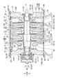
- the compressor 1 of this embodiment is provided with the casing 2, the bundle 10, and the control part 18 as shown in FIG.1 and FIG.2.
- an axial direction Da A radial direction based on the axis O is simply referred to as a radial direction Dr.
- the vertical direction Dv is defined as the vertical direction in FIG. 1 and FIG.
- the radial direction Dr and the axial direction Da perpendicular to the axis O, and the horizontal direction in FIGS. 1 and 2 is defined as a horizontal direction Dh.
- a direction around the rotor 11 around the axis O is a circumferential direction Dc.
- the casing 2 is disposed so as to cover the bundle 10 from the outer peripheral side.
- the casing 2 has a cylindrical shape with both ends opened around a central axis arranged in the same manner as an axis O of the rotor 11 described later.
- the cylindrical casing 2 includes an upper half casing 21 above the vertical direction Dv and a lower half casing 22 (see FIG. 2) below the vertical direction Dv.
- the upper half casing 21 has a cross section perpendicular to the axis O extending in the axial direction Da in a semicircular shape centering on the axis O.
- the upper half casing 21 opens downward in the vertical direction Dv so that the bundle 10 is fitted therein. Thereby, the upper half casing 21 has covered the outer peripheral surface of the bundle 10 accommodated in the inside from upper direction.
- the upper half casing 21 of the present embodiment is formed with flanges extending in the horizontal direction Dh at both ends in the circumferential direction Dc.
- the upper half casing 21 has upper half casing dividing surfaces 211 at both ends in the circumferential direction Dc.
- the upper half casing dividing surface 211 is one of the dividing surfaces when the casing 2 is divided vertically in the vertical direction Dv.
- the upper half casing dividing surface 211 is a flat surface extending in the radial direction Dr and the axial direction Da. That is, the upper half casing dividing surface 211 is a horizontal plane that faces downward in the vertical direction Dv.
- the lower half casing 22 has a cross section perpendicular to the axis O extending in the axial direction Da in a semicircular shape centering on the axis O.
- the lower half casing 22 is opened upward in the vertical direction Dv so that the bundle 10 is fitted therein. Thereby, the lower half casing 22 has covered the outer peripheral surface of the bundle 10 accommodated in the inside from the downward direction.
- flanges extending in the horizontal direction Dh are formed at both ends in the circumferential direction Dc.
- the lower half casing 22 has lower half casing dividing surfaces 221 at both ends in the circumferential direction Dc.
- the lower half casing dividing surface 221 is the other dividing surface when the casing 2 is divided vertically in the vertical direction Dv.
- the lower half casing dividing surface 221 is a flat surface extending in the radial direction Dr and the axial direction Da. That is, the lower half casing dividing surface 221 is a horizontal surface facing upward in the vertical direction Dv.
- the lower half casing 22 has a suction port 23 for supplying a process gas (fluid) to be compressed into the casing 2 and a discharge for discharging the compressed process gas from the inside of the casing 2. And a port 24.
- the bundle 10 is accommodated in the casing 2.
- the bundle 10 of the present embodiment includes a rotor 11, a bearing portion 12, a plurality of diaphragms 13, a plurality of heads 14, a head seal portion 15, a communication gap seal portion 16, and a fastening portion 17. Yes.
- the rotor 11, the bearing portion 12, the plurality of diaphragms 13, the plurality of heads 14, the head seal portion 15, the communication gap seal portion 16, and the fastening portion 17 are integrally movable.
- the rotor 11 is rotatable about the axis O.
- the rotor 11 includes a rotor shaft 111 that extends in the axial direction Da around the axis O, and a plurality of impellers 112 that rotate together with the rotor shaft 111.
- the impeller 112 is fixed to the outer peripheral surface of the rotor shaft 111.
- the impeller 112 compresses the process gas using centrifugal force by rotating together with the rotor shaft 111.
- the impeller 112 is provided in a plurality of stages in the axial direction Da with respect to the rotor shaft 111.
- the impeller 112 is a so-called open type impeller including a disk and a blade.
- the bearing portion 12 supports the rotor shaft 111 so as to be rotatable about the axis O.
- the bearing portion 12 is fixed to a head 14 described later.
- the bearing portion 12 includes a pair of journal bearings 121 provided at both ends of the rotor shaft 111 and a thrust bearing 122 provided at one end of the rotor shaft 111.
- the pair of journal bearings 121 plays a role of receiving a load in the radial direction Dr acting on the rotor shaft 111.
- These journal bearings 121 are respectively fixed to the pair of heads 14 using detachable fixing means (not shown) such as bolts.
- the thrust bearing 122 plays a role of receiving a load in the axial direction Da acting on the rotor shaft 111.
- the thrust bearing 122 is attached inside a box-shaped bearing cover 123.
- the bearing cover 123 is fixed to one head 14 using a detachable fixing means such as a bolt.
- the diaphragm 13 is disposed so as to cover the rotor 11 from the outer peripheral side.
- the diaphragm 13 has an annular shape around the axis O.
- the annular diaphragm 13 has an upper half diaphragm 131 that forms a semi-annular shape above the vertical direction Dv with respect to the axis O of the rotor 11, and a lower half diaphragm 132 that forms a semi-annular shape below.
- the upper half diaphragm 131 and the lower half diaphragm 132 are fixed by a detachable fixing means such as a bolt.
- a plurality (four in this embodiment) of the diaphragms 13 are arranged so as to be stacked in the axial direction Da.
- the plurality of diaphragms 13 have a cylindrical shape extending in the axial direction Da.
- a plurality of diaphragms 13 are fixed to each other so that a flow path to be introduced into the flow path of the impeller 112 is defined inside.
- the outer peripheral surfaces of the adjacent diaphragms 13 are fixed to each other by welding.
- welded portions 231 are formed at the corners facing the outer peripheral surface of the adjacent diaphragm 13.
- the plurality of diaphragms 13 are integrated by being fixed to each other by the welded portion 231.
- a welded groove 232 is formed in the adjacent diaphragm 13 so as to sandwich the welded part 231 from the axial direction Da.
- the weld groove 232 is recessed from the outer peripheral surfaces of the upper half diaphragm 131 and the lower half diaphragm 132 toward the inside in the radial direction Dr.
- the weld groove 232 is formed over the entire circumference in the circumferential direction Dc with respect to the outer circumferential surface of the diaphragm 13.
- the diaphragm 13 includes the suction port 236, the plurality of casing channels 235, and the discharge port 237 together with the casing 2 and the head 14 described later in order from the upstream side where the process gas flows. It is defined.
- the suction port 236 allows the process gas flowing from the outside of the casing 2 through the suction port 23 to flow into the casing flow path 235 inside the diaphragm 13.
- the suction port 236 allows the process gas to flow into the most upstream impeller 112.
- the inlet port 236 is provided with an inlet guide vane.
- the casing flow path 235 is formed in the diaphragm 13, and supplies process gas from the suction port 236 to the most upstream impeller 112, and impeller disposed downstream from the process gas discharged from the upstream impeller 112. 112, or the process gas discharged from the most downstream impeller 112 is supplied to the discharge port 237.
- the discharge port 237 discharges the process gas flowing through the inside of the diaphragm 13 to the outside of the casing 2 through the discharge port 24.
- the discharge port 237 discharges the process gas discharged from the most downstream impeller 112 to the outside.
- the pair of heads 14 are annular members, and are formed to have a size capable of closing the openings at both ends of the casing 2. Both ends of the rotor shaft 111 are inserted through the head 14.
- the suction-side head 141 disposed on one side (first side) in the axial direction Da with respect to the plurality of diaphragms 13, and the other side in the axial direction Da with respect to the plurality of diaphragms 13 ( And a discharge-side head 142 disposed on the second side.
- the suction side head 141 is disposed at a position closer to the suction port 236 than the discharge side head 142.
- the suction-side head 141 forms a suction port 236 together with the inlet wall 135 that is the diaphragm 13 disposed on the most side in the axial direction Da.
- a suction-side head exterior surface 241 that is a surface facing the one side in the axial direction Da of the suction-side head 141 faces the outside of the compressor 1.
- the suction-side head 141 is fixed using a plurality of integrated diaphragms 13 and bolt members 170. Specifically, the bolt member 170 is disposed through a groove recessed from the outer peripheral surface of the inlet wall 135.
- the inlet wall 135 and the suction-side head 141 are fixed to the upper half diaphragm 131 and the lower half diaphragm 132 by two bolt members 170 respectively.
- the fixing location by the bolt member 170 is not limited to two places, respectively, and there may be three or more places.
- the suction-side head 141 is integrated with the diaphragm 13.
- the discharge side head 142 is disposed at a position closer to the discharge port 237 than the suction side head 141.
- the discharge-side head 142 forms a discharge port 237 together with the final stage diaphragm 136 which is the diaphragm 13 disposed on the other side in the most axial direction Da.
- the discharge-side head 142 of this embodiment includes an outlet wall 145 that forms part of the discharge port 237 and a discharge-side head body 146 that is fixed to the outlet wall 145.
- the discharge-side head main body 146 is adjacent to the other side of the outlet wall portion 145 in the axial direction Da.
- a discharge-side head exterior surface 245 that faces the other side of the discharge-side head main body 146 in the axial direction Da faces the outside of the compressor 1.
- the distance in the axial direction Da from the suction-side head exterior surface 241 to the discharge-side head exterior surface 245 is approximately the same as the length of the casing 2 in the axial direction Da. That is, in this embodiment, the both ends of the casing 2 do not protrude from the suction side head exterior surface 241 and the discharge side head exterior surface 245.
- the head seal 15 seals between the outer peripheral surface of the head 14 and the inner peripheral surface of the casing 2.
- the head seal portion 15 of the first embodiment has a first head seal portion 151 provided on the suction side head 141 and a second head seal portion 152 provided on the discharge side head 142.
- first head seal portion 151 and the second head seal portion 152 have the same structure, the first head seal portion 151 will be described as an example.
- the first head seal portion 151 has an annular shape and surrounds the suction side head 141 over the entire circumference. As shown in FIG. 4, the first head seal portion 151 is an O-ring housed in a head seal mounting groove 251 formed on the outer peripheral surface of the suction side head 141. Two first head seal portions 151 are provided side by side in the axial direction Da with respect to the suction-side head 141.
- Two head seal mounting grooves 251 are formed side by side in the axial direction Da.
- the head seal mounting groove 251 is formed on the outer peripheral surface of the head 14 at a position as close as possible to the outside in the axial direction Da (on the side opposite to the side where the diaphragm 13 is disposed with respect to the head 14).
- the outside of the axial direction Da is a direction facing the outside of the compressor 1. Therefore, the outside of the suction direction head 141 in the axial direction Da is one side of the axial direction Da, and the discharge side head 142 is outside of the axial direction Da is the other side of the axial direction Da.
- the inside of the axial direction Da is a direction opposite to the outside of the axial direction Da and is a direction facing the center position of the axial direction Da of the bundle 10 in the compressor 1. Therefore, the inside of the suction-side head 141 in the axial direction Da is the other side of the axial direction Da, and the inside of the discharge-side head 142 in the axial direction Da is one side of the axial direction Da.
- the head seal mounting groove 251 is formed at a position close to the suction-side head exterior surface 241 that is close to one side of the axial direction Da in the suction-side head 141. Further, the head seal mounting groove 251 is formed at a position close to the discharge-side head exterior surface 245 that is a position close to the other side in the axial direction Da in the discharge-side head main body 146.
- the head seal mounting groove 251 may have the same shape as a gap seal mounting groove 261 described later.
- the communication gap seal 16 seals the communication gap C formed between the outer peripheral surface of the diaphragm 13 and the inner peripheral surface of the casing 2.
- the communication gap C is formed between the outer peripheral surface of the diaphragm 13 and the inner peripheral surface of the casing 2 in a state where the bundle 10 is accommodated in the casing 2.
- the communication gap C is an annular space extending in the axial direction Da so as to communicate the suction port 236 and the discharge port 237.
- the communication gap seal portion 16 of the present embodiment is an O-ring accommodated in a gap seal mounting groove 261 formed on the outer peripheral surface of the inlet wall 135. Only one communication gap seal portion 16 is provided for the communication gap C. Specifically, the gap seal mounting groove 261 is formed at a position close to the suction port 236 on the outer peripheral surface of the inlet wall 135 (a position close to one side in the axial direction Da as much as possible).
- the communication gap seal portion 16 has an annular shape and is formed over the entire circumference of the combined upper half diaphragm 131 and lower half diaphragm 132.
- the gap seal mounting groove 261 has a horizontal direction that is 90 degrees different in the circumferential direction Dc from the upper vertex of the vertical direction Dv in the upper half diaphragm 131 and the lower vertex of the vertical direction Dv in the lower half diaphragm 132. It forms so that it may become deep as it goes to the position of the both ends of Dh.
- the gap seal mounting groove 261 is configured such that the communication gap seal portion 16 has a radial direction Dr rather than the outer peripheral surface of the diaphragm 13 at the upper vertex of the vertical direction Dv in the upper half diaphragm 131 and the lower vertex of the vertical direction Dv in the lower half diaphragm 132. It is formed with a depth that protrudes outside.
- the gap seal mounting groove 261 is formed at a depth such that the communication gap seal portion 16 does not protrude from the outer peripheral surface of the diaphragm 13 at both ends in the horizontal direction Dh.
- the fastening part 17 fixes the discharge side head 142 and the last stage diaphragm 136 so that attachment or detachment is possible.
- a plurality of fastening portions 17 are provided evenly in the circumferential direction Dc around the axis O with respect to the ejection-side head 142.
- the fastening portion 17 of the present embodiment includes a fixed hole 171, a bolt mounting groove 172, a fastening through hole 173, a bolt member 174, and an elastic member 175.
- the fixed hole 171 includes a fixed screw hole 271 formed in the discharge-side head main body 146 and a fixed through-hole 272 formed in the outlet wall portion 145.
- the fixed screw hole 271 is formed in the discharge-side head main body inner side surface 244 which is a flat surface facing one side in the axial direction Da in the discharge-side head main body 146.
- the fixed screw hole 271 is a screw hole having a female screw inside, and the bolt member 174 can be fixed thereto.
- the fixed through hole 272 penetrates the outlet wall 145 in the axial direction Da at the same position as the fixed screw hole 271 when viewed from the axial direction Da.
- the fixed through-hole 272 passes through the outlet inner surface 242 facing the one side in the axial direction Da and the outlet outer surface 243 facing the other side of the axial direction Da in the outlet wall portion 145.
- the outlet inner surface 242 is a flat surface that comes into contact with the final stage diaphragm 136 when the discharge-side head 142 is fixed to the final stage diaphragm 136.
- the outlet outer surface 243 is a flat surface that comes into contact with the discharge-side head main body 146 when the outlet wall 145 is fixed to the discharge-side head main body 146.
- the outer peripheral surface of the final stage diaphragm 136 is recessed with a rectangular cross section.
- the bolt mounting groove 172 is formed such that the length in the axial direction Da is longer than the length of the bolt member 174.
- a plurality of bolt mounting grooves 172 are formed apart from each other in the circumferential direction Dc with respect to the outer peripheral surface of the final stage diaphragm 136.
- the fastening through hole 173 is formed in the final stage diaphragm 136.
- the fastening through hole 173 is formed at a position overlapping the fixed screw hole 271 and the fixed through hole 272 when viewed from the axial direction Da.
- the fastening through hole 173 passes through the groove inner side surface 273 facing one side in the axial direction Da and the final stage diaphragm contact surface 234 facing the other side in the axial direction Da.
- the groove inner side surface 273 is a part of a plane that forms the bolt mounting groove 172.
- the final stage diaphragm contact surface 234 is a plane that contacts the outlet inner side surface 242 when the final stage diaphragm 136 is fixed to the outlet wall 145.
- the bolt member 174 has a shaft portion 274 having a male screw on the outer peripheral surface, and a head portion 275 formed at the end of the shaft portion 274.
- the shaft portion 274 has a tip fixed to the fixed screw hole 271 while being inserted into the fastening through hole 173 and the fixed through hole 272.
- the head 275 is formed in a size that can be accommodated in the bolt mounting groove 172. That is, the head 275 is disposed in the bolt mounting groove 172 with the shaft portion 274 fixed to the fixed screw hole 271.
- the elastic member 175 is a plurality of disc spring washers disposed between the head 275 and the groove inner side surface 273. A plurality of elastic members 175 are stacked. The elastic member 175 is sandwiched between the surface facing the other side of the axial direction Da of the head 275 and the inner surface 273 of the groove in a state where the shaft portion 274 is inserted.
- the restricting portion 18 is provided on at least one of the casing 2 and the head 14.
- the restricting portion 18 restricts the position of the head 14 in the axial direction Da with respect to the casing 2.
- the restricting portion 18 of the first embodiment is provided over both the casing 2 and the head 14.
- the restricting portion 18 is provided for each of the suction side head 141 and the discharge side head 142.
- the restricting portion 18 is formed on the fitting recess 181 formed on the inner peripheral surface of the casing 2, and on the outer peripheral surfaces of the suction side head 141 and the discharge side head main body 146. It has the fitting recessed part 181 and the fitting convex part 182 fitted.
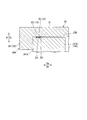
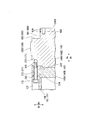
- FIG. 4 is an enlarged view of a main part for explaining the restricting portion 18 provided between the suction-side head 141 and the upper half casing 21.
- the restricting portions 18 are provided corresponding to the suction side head 141 and the discharge side head 142, respectively.
- the restricting portion 18 around the suction side head 141 will be described as an example with reference to FIG.
- the fitting recess 181 has a rectangular cross section from the inner peripheral surface of the casing 2 and is recessed over the entire periphery. Two fitting recesses 181 are formed apart in the axial direction Da corresponding to the position where the suction-side head 141 is disposed. The fitting recess 181 is formed in each of the upper half casing 21 and the lower half casing 22.
- the fitting convex part 182 has a rectangular cross section and protrudes from the outer peripheral surface of the suction side head 141 over the entire circumference.
- the fitting convex part 182 is formed inside the axial direction Da with respect to the head seal mounting groove 251.
- Two fitting convex portions 182 are formed side by side in the axial direction Da with respect to the suction-side head 141.
- the compressor manufacturing method S ⁇ b> 1 of the present embodiment includes a preparation step S ⁇ b> 10, a bundle arrangement step S ⁇ b> 30, and an upper half casing arrangement step S ⁇ b> 40.
- preparation step S10 parts necessary for manufacturing the compressor 1 are prepared.
- preparatory process S10 of 1st embodiment casing preparatory process S11 and bundle preparatory process S12 are implemented simultaneously.
- the upper half casing 21 and the lower half casing 22 in which the fitting recess 181 is formed are manufactured and prepared.
- the preparation step S ⁇ b> 10 the rotor 11, the bearing portion 12, the upper half diaphragm 131, the lower half diaphragm 132, the suction side head 141, the discharge side head 142, the communication gap seal portion 16, and the fastening portion 17. are prepared by being manufactured.
- the diaphragm 13 is formed in an annular shape by fixing the upper half diaphragm 131 on the lower half diaphragm 132 by a fixing means such as a bolt with the rotor 11 disposed therein. Thereafter, the outer peripheral surfaces of the adjacent diaphragms 13 are welded to form a welded portion 231. Thereby, the plurality of diaphragms 13 are integrated.
- a communication gap seal portion 16 is attached to the outer peripheral surface of the integrated diaphragm 13.
- the head seal portion 15 is attached to the suction side head 141 and the discharge side head 142 in which the fitting convex portion 182 is formed.
- the bearing portion 12 is fixed to the suction side head 141 and the discharge side head 142. Thereafter, the suction-side head 141 is fixed to the diaphragm 13 by the bolt member 170. Further, the discharge-side head 142 is fixed to the diaphragm 13 by the fastening portion 17. By these, the bundle 10 integrated as one component is prepared.
- the bundle 10 is arranged from above in the vertical direction Dv with respect to the lower half casing 22, as shown in FIG.
- An eyebolt 501 is fixed to the outer peripheral surface of the bundle 10 in advance.
- the eyebolts 501 are attached to the outer peripheral surface of the suction-side head 141 at two locations and to the outer peripheral surface of the discharge-side head 142, respectively.
- the eyebolt 501 is attached at a position that is 45 degrees different from the upper end in the vertical direction Dv in the circumferential direction Dc. As shown in FIG.
- a plurality of rod-shaped guide bars 502 are attached to the lower half casing 22 so as to extend upward from the lower half casing dividing surface 221 in the vertical direction Dv.
- a guide plate 503 guided along the guide rod 502 is attached to the bundle 10 by inserting the guide rod 502.
- the guide plate 503 is attached to the outer peripheral surface of the diaphragm 13 corresponding to the position where the guide rod 502 is provided.
- the wire 504 is fixed to the eyebolt 501.
- the bundle 10 is once lifted above the vertical direction Dv. Thereafter, the horizontal position of the bundle 10 is adjusted so that the guide bar 502 is inserted into the guide plate 503, and the bundle 10 is lowered. As a result, the bundle 10 descends along the guide bar 502.
- the bundle 10 When the bundle 10 is lowered to the vicinity of the lower half casing 22, the guide plates 503 are respectively removed from the bundle 10, and the pair of guide rods 502 are respectively removed from the lower half casing 22. Thereafter, the bundle 10 is lowered to the inner peripheral side of the lower half casing 22.
- the bundle 10 When the bundle 10 is arranged inside the lower half casing 22, the fitting convex portion 182 formed on the suction side head 141 and the discharge side head with respect to the fitting concave portion 181 formed on the lower half casing 22.
- the bundle 10 is lowered so that the fitting convex part 182 formed in the main body 146 fits.
- a communication gap C is formed between the outer peripheral surface of the lower half diaphragm 132 and the inner peripheral surface of the lower half casing 22.
- the communication gap C is sealed by the communication gap seal portion 16 contacting the inner peripheral surface of the lower half casing 22.
- the upper half casing arrangement step S40 is performed after the bundle arrangement step S30.
- the upper half casing 21 is arranged from above in the vertical direction Dv with respect to the bundle 10 fitted in the lower half casing 22.
- a wire 504 is fixed to the flange of the upper half casing 21. By winding the wire 504 using a crane, the upper half casing 21 is once lifted above the vertical direction Dv. Thereafter, the upper half casing 21 is lowered above the bundle 10.
- the horizontal position is adjusted so that the bundle 10 is accommodated on the inner peripheral side of the upper half casing 21.
- the fitting convex portion 182 formed on the suction side head 141 and the discharge side head with respect to the fitting concave portion 181 formed on the upper half casing 21.
- the upper half casing 21 is lowered so that the fitting convex part 182 formed in the main body 146 fits.
- the positions of the suction-side head 141 and the discharge-side head main body 146 in the axial direction Da are restricted with respect to the upper half casing 21.
- a communication gap C is formed between the outer peripheral surface of the upper half diaphragm 131 and the inner peripheral surface of the upper half casing 21.
- the communication gap C is sealed by the communication gap seal portion 16 contacting the inner peripheral surface of the upper half casing 21.
- the upper half casing 21 and the lower half casing 22 are fixed by the fixing means while the upper half casing dividing surface 211 is in contact with the lower half casing dividing surface 221, and the compressor 1 is completed.
- the suction port 236 and the discharge port 237 are communicated with each other, formed between the outer peripheral surface of the diaphragm 13 and the inner peripheral surface of the casing 2.
- the communication gap C is sealed by the communication gap seal portion 16.
- the communication gap C is formed between the outer peripheral surface of the diaphragm 13 and the inner peripheral surface of the casing 2, thereby preventing interference and the like when assembling the casing 2 and the bundle 10 having the upper and lower split structures. Can be improved.
- the communication gap C since the communication gap C is sealed, it is possible to prevent the high-pressure process gas supplied to the discharge port 237 from leaking from the suction port 236 through the communication gap C. Thereby, the leak between the outer peripheral surfaces of the diaphragm 13 can be reduced.
- the communication gap seal portion 16 is provided only at one place on the outer peripheral surface of the inlet wall 135 in the communication gap C. Therefore, the high-pressure process gas that has flowed into the communication gap C from the discharge port 237 flows into a position where the communication gap seal portion 16 is provided. Therefore, the pressure around the outer peripheral surface of all the diaphragms 13 becomes high. Therefore, surface pressure is applied to the dividing surface of the casing 2 having the upper and lower divided structures, and the sealing performance of each diaphragm 13 can be improved.
- the restricting portion 18 a fitting concave portion 181 formed on the inner peripheral surface of the casing 2 and a fitting convex portion 182 formed on the outer peripheral surfaces of the suction side head 141 and the discharge side head main body 146 are provided. Yes. Therefore, the position of the head 14 in the axial direction Da relative to the casing 2 can be regulated with a simple structure that merely forms a concavo-convex shape. Further, the restricting portion 18 that restricts the position of the head 14 in the axial direction Da with respect to the casing 2 is directly formed as a part of the casing 2 and the head 14, not a separate member.
- the structure that restricts the position of the bundle 10 and the casing 2 in the axial direction Da is only the fitting recess 181 and the fitting projection 182, and is not provided in the diaphragm 13. For this reason, the number of parts to be assembled and the positioning locations in the axial direction Da are reduced, and adjustment when assembling the casing 2 and the bundle 10 is facilitated. As a result, the assemblability can be further improved.
- Both ends of the diaphragm 13 in the horizontal direction Dh are close to the dividing surface of the casing 2. Therefore, when the protruding amount of the communication gap seal portion 16 increases at both ends in the horizontal direction Dh, when the upper half casing 21 is attached to the lower half casing 22, the O-ring is sandwiched between the split surfaces or rubbed against the edges. May cause damage.
- the gap seal mounting groove 261 is formed so as to become deeper toward both ends in the horizontal direction Dh. Therefore, the communication gap seal portion 16 fitted in the gap seal mounting groove 261 moves from the outer peripheral surface of the diaphragm 13 toward the both ends in the horizontal direction Dh from the upper vertex in the vertical direction Dv or the lower vertex in the vertical direction Dv.
- the amount of protrusion is reduced. Thereby, damage to the O-ring that is the communication gap seal portion 16 when the upper half casing 21 is attached to the lower half casing 22 can be reduced.
- the amount of protrusion of the communication gap seal portion 16 is the smallest at both ends in the horizontal direction Dh. Therefore, damage to the communication gap seal portion 16 when the upper half casing 21 is attached to the lower half casing 22 can be more effectively reduced.
- the process gas that has been compressed and becomes high temperature and high pressure flows through the vicinity of the discharge port 237, whereby the final stage diaphragm 136 and the outlet wall portion 145 are heated, and the thermal extension in the axial direction Da is increased. May occur.
- the final stage diaphragm 136 and the outlet wall portion 145 extend in the axial direction Da between the tip and the head 275.
- a pulling force in the axial direction Da acts on the boundary between the shaft portion 274 and the head portion 275 of the bolt member 174.
- the fastening portion 17 is not limited to being used for fixing the discharge side head 142 and the final stage diaphragm 136.
- the fastening portion 17 may be used for fixing the suction side head 141 and the inlet wall 135.
- the elastic member 175 is not limited to being a disc spring washer.
- the elastic member 175 may be a rubber material or a spring member.
- the fixed hole 171 is not limited to the structure formed in the discharge-side head 142.
- the fixed hole 171 may be formed in the final stage diaphragm 136.
- the fixing of the adjacent diaphragms 13 is not limited to welding, and other fixing means may be used. In the present embodiment, four diaphragms 13 are provided. However, the number of diaphragms 13 is not limited to this, and the design can be appropriately changed according to the number of stages of the impeller 112.
- the communication gap seal portion 16 is not limited to being provided on the outer peripheral surface of the diaphragm 13 as a part of the bundle 10.
- the communication gap seal portion 16 may be provided on the casing 2 side or may be provided as a separate member as long as the communication gap C can be sealed.
- the restricting portion 18A is provided in the casing 2A.
- the upper half casing 21 ⁇ / b> A has an upper half casing body 31 and an upper half protrusion 32.
- the lower half casing 22 ⁇ / b> A includes a lower half casing body 35 and a lower half protruding portion 36.
- the upper half protruding portion 32 and the lower half protruding portion 36 constitute a restricting portion 18A in the present embodiment. That is, the restricting portion 18A of the second embodiment is formed only on the casing 2A.
- the upper half casing body 31 has a cross section orthogonal to the axis O extending in the axial direction Da in a semicircular shape centering on the axis O.
- the upper half casing body 31 is opened facing downward in the vertical direction Dv so that the bundle 10 is fitted therein. Thereby, the upper half casing main body 31 has covered the upper side of the outer peripheral surface of the bundle 10 accommodated in the inside.
- the upper half casing body 31 has upper half casing dividing surfaces 211 at both ends in the circumferential direction Dc. That is, the upper half casing body 31 has the same shape as the upper half casing 21 of the first embodiment.
- the lower half casing body 35 has a cross section perpendicular to the axis O extending in the axial direction Da in a semicircular shape centering on the axis O.
- the lower half casing body 35 is opened upward in the vertical direction Dv so that the bundle 10 is fitted therein. Thereby, the lower half casing main body 35 has covered the lower side of the outer peripheral surface of the bundle 10 accommodated in the inside.
- the lower half casing body 35 has lower half casing dividing surfaces 221 at both ends in the circumferential direction Dc. That is, the lower half casing body 35 has the same shape as the lower half casing 22 of the first embodiment. Therefore, the lower half casing 22A and the upper half casing 21A are combined to form a cylindrical shape having both ends opened.
- the upper half protrusions 32 are respectively formed at both ends of the upper half casing body 31 in the axial direction Da.
- the upper half projecting portion 32 projects from the upper half casing body 31 toward the inside in the radial direction Dr so as to form a semi-annular shape.
- the upper half projecting portion 32 includes a first upper half projecting portion 321 provided on the outer side in the axial direction Da with respect to the suction side head 141A, and an outer side in the axial direction Da with respect to the discharge side head 142A. And a second upper half projecting portion 322 provided on the head.
- the first upper half protrusion 321 is formed at one end of the upper half casing body 31 in the axial direction Da. As shown in FIG. 12, the surface of the first upper half protrusion 321 facing the other side in the axial direction Da is in contact with the suction-side head exterior surface 241A that is the end surface facing the outside of the axial direction Da in the suction-side head 141A. ing.
- the second upper half protrusion 322 is formed at the other end of the upper half casing body 31 in the axial direction Da.
- the surface of the second upper half projecting portion 322 facing one side in the axial direction Da is in contact with the discharge-side head exterior surface 245A, which is the end surface facing the outside of the axial direction Da in the discharge-side head main body 146A.
- the lower half protrusions 36 are respectively formed at both ends of the lower half casing body 35 in the axial direction Da.
- the lower half projecting portion 36 projects from the lower half casing body 35 toward the inside in the radial direction Dr so as to form a semi-annular shape.
- the lower half protrusion 36 includes a first lower half protrusion 361 provided on the outer side in the axial direction Da with respect to the suction-side head 141A, and an outer side in the axial direction Da with respect to the discharge-side head 142A. And a second lower half projecting portion 362 provided on the second lower half.
- the first lower half protrusion 361 is formed at one end of the lower half casing body 35 in the axial direction Da.
- the surface of the first lower half projecting portion 361 facing the other side in the axial direction Da is in contact with the suction-side head exterior surface 241A that is the end surface facing the outside of the axial direction Da in the suction-side head 141A.
- the surface of the first lower half projecting portion 361 facing the other side in the axial direction Da is formed at the same position as the surface of the first upper half projecting portion 321 facing the other side of the axial direction Da in the axial direction Da. .
- the second lower half protrusion 362 is formed at the other end of the lower half casing body 35 in the axial direction Da.
- the surface of the second lower half protrusion 362 facing the one side in the axial direction Da is in contact with the discharge-side head exterior surface 245A, which is the end surface facing the outside of the axial direction Da in the discharge-side head 142A.
- the surface of the second lower half projecting portion 362 facing one side in the axial direction Da is formed at the same position as the surface of the second upper half projecting portion 322 facing one side of the axial direction Da in the axial direction Da. .
- the fitting convex part 182 is not formed in the head 14A of 2nd embodiment.
- a gap expanding recess 370 is formed on the inner side in the axial direction Da from the head seal mounting groove 251 on the outer peripheral surface of the head 14A (on the side where the diaphragm 13 is disposed with respect to the head 14A).
- the gap expanding recess 370 is recessed from the outer circumferential surface of the head 14A so as to increase the gap with the inner circumferential surface of the casing 2A.
- the position of Da can be regulated. Since the upper half protrusion 32 and the lower half protrusion 36 are located outside the compressor 1A, it is difficult to be limited in space. Therefore, even if the thrust force generated in the bundle 10 is large depending on the type of process gas to be compressed, the upper half protrusion 32 and the lower half protrusion 36 can be enlarged in accordance with the force generated in the bundle 10. Thereby, the position of the bundle 10 with respect to the casing 2A can be stably held. In addition, it can be confirmed that the position of the bundle 10 with respect to the casing 2A is regulated at a position that can be viewed from the outside.
- both ends of the casing 2B are formed to protrude outward in the axial direction Da from the suction side head 141B and the discharge side head 142B. That is, the length in the axial direction Da of the casing 2B of the third embodiment is longer than the distance in the axial direction Da from the suction-side head exterior surface 241B to the discharge-side head exterior surface 245B.
- the regulating portion 18B of the third embodiment has other members in addition to the casing 2B and the head 14B.
- the restriction portion 18 ⁇ / b> B includes a restriction accommodation recess 410, a head restriction accommodation groove 420, a first restriction member 430, and a second restriction member 440.
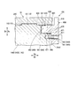
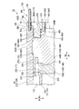
- FIG. 14 is an enlarged view of a main part for explaining the restricting portion 18B provided between the suction-side head 141B and the upper half casing 21B.
- the restricting portion 18B of the third embodiment is provided corresponding to each of the suction side head 141B and the discharge side head 142B.
- the restricting portion 18B around the suction side head 141B will be described as an example with reference to FIG. I will explain.
- the regulation accommodation recessed part 410 is formed in the part protruded to the outer side of the axial direction Da rather than the suction side head 141B in the edge part of the casing 2B.
- the restriction accommodating recess 410 is recessed with a rectangular cross section from the inner peripheral surface of the casing 2B so that a part thereof is located outside the axial direction Da with respect to the suction-side head 141B.
- the regulation accommodation recess 410 includes a regulation accommodation recess bottom surface 411 facing the inside in the radial direction Dr, a regulation accommodation recess first surface 412 facing the inside in the axial direction Da, and a regulation accommodation recess second surface 413 facing the outside in the axial direction Da. It consists of and.
- the regulation accommodating recess bottom surface 411 is a surface parallel to the inner peripheral surface of the casing 2B.
- the regulation accommodation recessed part 1st surface 412 is a plane which connects the inner peripheral surface of the casing 2B, and the short side outside the axial direction Da in the regulation accommodation recessed part bottom face 411.
- the regulation accommodation recessed part 2nd surface 413 is a plane which connects the inner peripheral surface of the casing 2B, and the short side inside the axial direction Da in the regulation accommodation recessed part bottom face 411.
- the head regulation accommodation groove 420 is formed at a corner portion formed by the outer peripheral surface of the suction side head 141B and the suction side head exterior surface 241B (surface facing the outside in the axial direction Da).
- the head regulation accommodation groove 420 is formed outside the head seal attachment groove 251 in the axial direction Da.
- the head regulation accommodation groove 420 is composed of a regulation accommodation groove first surface 421 facing the outside in the radial direction Dr and a regulation accommodation groove second surface 422 facing the outside in the axial direction Da.
- the regulation accommodating groove first surface 421 is a surface parallel to the outer peripheral surface of the suction side head 141B, and is connected to the suction side head exterior surface 241B.
- the restriction accommodating groove second surface 422 is a plane parallel to the suction side head exterior surface 241B, and is a surface connecting the outer peripheral surface of the suction side head 141B and the restriction accommodating groove first surface 421.
- the first regulating member 430 is a member that regulates the position of the suction-side head 141B in the axial direction Da relative to the casing 2B by being housed in the regulating housing recess 410 together with the second regulating member 440.
- the first regulating member 430 has an L-shaped cross section. Specifically, in the first restricting member 430, a first accommodating portion 431 accommodated in the restricting accommodating recess 410 and a second accommodating portion 432 accommodated in the head restricting accommodating groove 420 are integrally formed.
- the first accommodating portion 431 has a rectangular shape.
- the second housing portion 432 is formed to project from the first housing portion 431 in a rectangular shape toward the inner side in the axial direction.
- the second restriction member 440 is accommodated in the restriction accommodation recess 410 in a state adjacent to the first restriction member 430 outside the first restriction member 430 in the axial direction Da.
- the second regulating member 440 has a rectangular shape.
- the first restricting member 430 moves inward in the axial direction Da while the first accommodating portion 431 is inserted into the restricting accommodating recess 410. Then, the second storage portion 432 is inserted into the head restriction storage groove 420. Thereafter, the second restricting member 440 is press-fitted into the restricting housing recess 410 outside the first restricting member 430 in the axial direction Da. As a result, the first restricting member 430 and the second restricting member 440 are in contact with each other while being accommodated in the restricting accommodating recess 410 and the head restricting accommodating groove 420.
- the second housing portion 432 comes into contact with the regulation housing groove second surface 422, and the second regulation member 440 comes into contact with the regulation housing recess first surface 412.
- the first restriction member 430 and the second restriction member 440 are sandwiched between the restriction accommodation recess first surface 412 and the restriction accommodation groove second surface 422 and cannot be removed.
- the first restriction member 430 and the second restriction member 440 are accommodated in the restriction accommodation recess 410 and the head restriction accommodation groove 420. Thereby, the position of the axial direction Da of the suction-side head 141B and the discharge-side head 142B with respect to the casing 2B can be regulated from the outside of the compressor 1B. Furthermore, the first regulating member 430 and the second regulating member 440 can be attached from the outside after the upper half casing 21B is installed on the bundle 10.
- ⁇ 4th embodiment >> Next, a fourth embodiment of the compressor of the present invention will be described with reference to FIGS. 15 to 17.
- the compressor 1C shown in the fourth embodiment is different from the first embodiment in the configuration of the head seal portion. Therefore, in the description of the fourth embodiment, the same parts as those in the first embodiment to the third embodiment are denoted by the same reference numerals and redundant description is omitted.
- the compressor 1C of the fourth embodiment includes a head seal portion 15C having a separate member for sealing between the head 14C and the casing 2C.
- the head seal portion 15 ⁇ / b> C of the fourth embodiment includes a seal ring 600, a seal ring fixing hole 650, a ring insertion groove 660, and an inner ring seal portion 670.
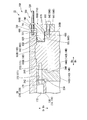
- FIG. 16 is an enlarged view of a main part for explaining the head seal portion 15C provided between the discharge-side head 142C and the upper half casing 21C.
- the head seal portion 15C of the fourth embodiment is provided corresponding to each of the suction side head 141C and the discharge side head 142C.
- the head seal portion 15C around the discharge side head 142C will be described as an example with reference to FIG. Will be described.
- the seal ring 600 is detachable from the outer side in the axial direction Da with respect to the discharge-side head main body 146C. That is, the seal ring 600 is movable in the axial direction Da from the outside of the discharge-side head main body 146C and the casing 2C.
- the seal ring 600 is attached from the outside after the casing 2 ⁇ / b> C is attached to the bundle 10.
- the seal ring 600 is an annular member centered on the axis O.
- the seal ring 600 according to the present embodiment includes a ring main body 610, a ring insertion portion 620, an outer ring seal portion 630, and a ring fixing member 640.
- the seal ring 600 is fixed to the seal ring fixing hole 650.
- the seal ring fixing hole 650 is formed in the discharge-side head exterior surface 245C.
- the seal ring fixing hole 650 is a screw hole having a female screw inside.
- the ring insertion portion 620 can be inserted.
- the ring insertion groove 660 is formed at a corner formed by the outer peripheral surface of the discharge-side head main body 146C and the discharge-side head exterior surface 245C (surface facing the outside in the axial direction Da).
- the ring insertion groove 660 is recessed from the outer peripheral surface of the discharge-side head exterior surface 245C and the discharge-side head main body 146C in a rectangular shape.
- the ring insertion groove 660 forms a space in which the ring insertion portion 620 can be inserted between the inner peripheral surface of the casing 2C.
- the ring insertion groove 660 is formed outside the fitting protrusion 182 in the axial direction Da.
- the ring insertion groove 660 is formed outside the seal ring fixing hole 650 in the radial direction Dr.
- the ring insertion groove 660 includes a ring insertion groove first surface 661 facing the outside in the radial direction Dr and a ring insertion groove second surface 662 facing the outside in the axial direction Da.
- the ring insertion groove first surface 661 is a surface parallel to the outer peripheral surface of the discharge-side head main body 146C and is connected to the discharge-side head exterior surface 245C.
- the ring insertion groove second surface 662 is a plane parallel to the discharge-side head exterior surface 245C, and is a surface connecting the outer peripheral surface of the discharge-side head main body 146C and the ring insertion groove first surface 661.
- the inner ring seal portion 670 can seal between the inner peripheral surface of the ring insertion portion 620 and the ring insertion groove first surface 661.
- the inner ring seal portion 670 has an annular shape and surrounds the discharge-side head main body 146C over the entire circumference.
- the inner ring seal portion 670 of this embodiment is an O-ring accommodated in an inner attachment groove 671 formed in the ring insertion groove first surface 661.
- Two inner ring seal portions 670 are provided side by side in the axial direction Da with respect to the ring insertion groove first surface 661.
- Two inner mounting grooves 671 are formed side by side in the axial direction Da.
- the inner mounting groove 671 is formed at a position as close as possible to the outer side in the axial direction Da on the ring insertion groove first surface 661.
- the ring body 610 has a cross-sectional plate shape and is formed in an annular shape centering on the axis O.
- the ring insertion part 620 protrudes from the ring main body 610 over the entire circumference with a rectangular cross section. That is, the ring insertion portion 620 protrudes from the ring body 610 in an annular shape.
- the ring insertion portion 620 has a shape that can be inserted into the ring insertion groove 660.
- the amount of protrusion of the ring insertion portion 620 from the ring body 610 is greater than the depth of the ring insertion groove 660 in the axial direction Da (the distance in the axial direction Da between the discharge-side head exterior surface 245C and the ring insertion groove second surface 662). It has been shortened.
- the surface on the side where the ring insertion portion 620 protrudes is cut out outside the radial direction Dr from the position where the ring insertion portion 620 protrudes.
- the ring body 610 has an inner thickness in the radial direction Dr with respect to a position where the ring insertion portion 620 protrudes, and a thickness outside the radial direction Dr with respect to a position where the ring insertion portion 620 protrudes. And thick.
- a ring body through-hole 611 is formed in the ring body 610.
- the ring main body through hole 611 is formed at a position overlapping the seal ring fixing hole 650 when viewed from the axial direction Da in a state where the ring insertion portion 620 is inserted into the ring insertion groove 660.
- the outer ring seal portion 630 can seal between the outer peripheral surface of the ring insertion portion 620 and the inner peripheral surface of the casing 2C.
- the outer ring seal portion 630 has an annular shape and surrounds the ring insertion portion 620 over the entire circumference.
- the outer ring seal portion 630 of this embodiment is an O-ring accommodated in an outer mounting groove 631 formed on the outer peripheral surface of the ring insertion portion 620.
- Two outer ring seal portions 630 are provided side by side in the axial direction Da with respect to the outer peripheral surface of the ring insertion portion 620.
- Two outer mounting grooves 631 are formed side by side in the axial direction Da.
- the outer mounting groove 631 is formed at a position that is disposed on the inner side in the axial direction Da than the inner mounting groove 671 in a state where the ring insertion portion 620 is inserted into the ring insertion groove 660.
- the ring fixing member 640 is a bolt having a ring fixing shaft portion 641 having an external thread on the outer peripheral surface and a ring fixing head portion 642 formed at the end of the ring fixing shaft portion 641.
- the ring fixing shaft portion 641 has a tip fixed to the seal ring fixing hole 650 while being inserted into the ring body through-hole 611.
- the ring fixing head 642 is disposed outside the ring body 610 in the axial direction Da.
- an insertion gap enlarged diameter portion 680 is formed to increase the distance between the outer peripheral surface of the ring insertion portion 620 and the inner peripheral surface of the casing 2C at a position shifted outward in the axial direction Da with respect to the outer ring seal portion 630. Yes. Specifically, the insertion gap enlarged diameter portion 680 is formed at the end of the casing 2 ⁇ / b> C that is outside the outer ring seal portion 630 in the axial direction Da. The insertion gap enlarged diameter portion 680 is recessed from the inner peripheral surface of the casing 2C so as to increase the gap between the outer peripheral surface of the ring insertion portion 620 and the inner peripheral surface of the casing 2C.
- the insertion gap diameter is increased.
- the part 680 widens the gap with the outer peripheral surface of the ring insertion part 620 to 1.0 mm or more.
- the insertion gap enlarged diameter portion 680 is formed over the entire circumference at both ends in the axial direction Da of the casing 2C.
- the compressor manufacturing method S14 of the present embodiment includes a preparation step S104, a bundle arrangement step S30, an upper half casing arrangement step S40, and a head seal portion movement step S60.
- a preparation step S104 a preparation step S104
- a bundle arrangement step S30 a bundle arrangement step S30
- an upper half casing arrangement step S40 a head seal portion movement step S60.
- the casing preparatory step S114, the bundle preparatory step S124, and the head seal portion preparatory step S50 are performed simultaneously.
- the upper half casing 21C and the lower half casing 22C are prepared. At that time, insertion gap enlarged diameter portions 680 are respectively formed at both ends of the upper half casing 21C and the lower half casing 22C in the axial direction Da.
- the rotor 11, the bearing portion 12, the upper half diaphragm 131, the lower half diaphragm 132, the suction side head 141C, the discharge side head 142C, the communication gap seal portion 16, and the fastening portion 17 are provided.
- the seal ring 600 are prepared, for example.
- the suction side head 141C and the discharge side head 142C are formed with a ring insertion groove 660 and attached with an inner ring seal portion 670.
- the head seal part moving step S60 is performed after the upper half casing arranging step S40.
- the seal ring 600 is attached to the suction side head 141C and the discharge side head 142C from the outside, and the ring insertion portion 620 is connected to the outer peripheral surface of the suction side head 141C and the inner peripheral surface of the casing 2C. Or between the outer peripheral surface of the discharge-side head 142C and the inner peripheral surface of the casing 2C.
- the ring insertion portion 620 is inserted into the ring insertion groove 660 from the outside in the axial direction Da, and the ring main body 610 is fixed to the suction-side head 141C and the discharge-side head 142C by the ring fixing member 640. .
- the inner ring seal part 670 accommodated in the inner attachment groove 671 comes into contact with the inner peripheral surface of the ring insertion part 620.
- the outer ring seal portion 630 housed in the outer mounting groove 631 comes into contact with the inner peripheral surface of the casing 2C.
- the seal ring 600 is attached after the bundle 10 and the casing 2C are assembled. Thereby, it is possible to seal between the suction side head 141C and the discharge side head 142C and the casing 2C. Therefore, before the bundle 10 and the casing 2C are assembled, the outer ring seal portion 630 is not provided, and the inner ring seal portion 670 is a ring that is recessed from the outer peripheral surfaces of the suction side head 141C and the discharge side head 142C. It is provided in the insertion groove 660.
- the seal ring 600 is detachable from the outside, damage to the outer ring seal portion 630 and the inner ring seal portion 670 can be reliably prevented. Thereby, the sealing performance between the head 14C and the casing 2C can be secured more stably.
- insertion gap enlarged diameter portions 680 are formed at both ends of the casing 2C. Thereby, the clearance gap between the outer peripheral surface of the ring insertion groove 660 and the inner peripheral surface of the casing 2C becomes large. As a result, when the ring insertion portion 620 is inserted into the ring insertion groove 660, damage caused by the outer ring seal portion 630 rubbing against the inner peripheral surface of the casing 2C can be reduced.
- outer ring seal portion 630 and the inner ring seal portion 670 are each provided in duplicate in the axial direction Da. Thereby, the sealing performance between the head 14C and the casing 2C can be improved.
- the seal ring 600 is not limited to a structure that is fixed only to the head 14C as in the fourth embodiment.
- the seal ring 600 may be a structure that is fixed only to the casing 2C, or may be a structure that is fixed to the head 14C and the casing 2C.
- the ring insertion groove 660 is not limited to being formed only in the head 14C.
- the ring insertion groove 660 may be formed only in the casing 2C, or may be formed across the head 14C and the casing 2C. Further, if a space in which the ring insertion portion 620 can be inserted is formed between the head 14C and the casing 2C, the ring insertion groove 660 may not be formed.
- the insertion gap enlarged diameter portion 680 is not limited to being provided only on the outer ring seal portion 630 side.
- the insertion gap enlarged diameter portion 680 may be formed on the inner ring seal portion 670 side.
- the insertion gap enlarged diameter portion 680 is formed at, for example, a corner portion between the ring insertion groove first surface 661 and the discharge-side head exterior surface 245C.
- the inner ring seal portion 670 is not limited to being attached to the head 14C as in the present embodiment.
- the inner ring seal portion 670 is attached to, for example, the inner peripheral surface of the ring insertion portion 620. May be.
- outer ring seal portion 630 is not limited to being attached to the ring insertion portion 620 as in the present embodiment.
- the outer ring seal portion 630 is attached to, for example, the inner peripheral surface of the casing 2C. May be.
- ⁇ 5th embodiment a fifth embodiment of the compressor of the present invention will be described with reference to FIGS.
- the compressor 1D shown in the fifth embodiment is different from the fourth embodiment in that the compressor 1D includes a movement holding unit that moves the head relative to the casing. Therefore, in the description of the fifth embodiment, the same reference numerals are given to the same parts as those in the first to fourth embodiments, and redundant description is omitted.
- the final stage diaphragm 136 is not fixed to the discharge-side head 142D. Therefore, the discharge-side head 142D is movable relative to the final stage diaphragm 136 in the axial direction Da while being accommodated in the casing 2D. Specifically, the length in the axial direction Da of the fitting convex portion 182D formed in the discharge-side head body 146D is shorter than the length in the axial direction Da of the fitting concave portion 181D formed in the casing 2D. Yes.
- the compressor 1D further includes a movement holding unit 700.
- the movement holding unit 700 can move the discharge-side head 142D relative to the casing 2D in the axial direction Da, and can hold the position of the discharge-side head 142D at an arbitrary position in the axial direction Da.
- the movement holding unit 700 holds the discharge-side head 142D at a position farthest from the final stage diaphragm 136 and at a position where it cannot move toward the outside in the axial direction Da.
- the position that is farthest from the final stage diaphragm 136 and cannot move outward in the axial direction Da is directed outward in the axial direction Da of the fitting convex portion 182D formed in the discharge-side head body 146D.
- the surface is a position where the inner surface in the axial direction Da of the fitting recess 181D formed in the casing 2D contacts the surface.
- the movement holding unit 700 includes a fixed member 710, a shaft member 720, a first nut 730, and a second nut 740.
- the fixed member 710 is fixed to the discharge-side head main body 146D.
- the member to be fixed 710 in the present embodiment is a ring main body 610D of the seal ring 600D, and is integrated with the ring insertion portion 620.
- a fixed member communication hole 711 that communicates in the axial direction Da is formed in the ring main body 610D.
- the fixed member communication hole 711 is formed at a position overlapping the casing 2D when viewed from the axial direction Da in a state where the ring insertion portion 620 is inserted into the ring insertion groove 660. Specifically, the fixed member communication hole 711 is formed on the opposite side of the ring body through hole 611 and the radial direction Dr with respect to the position where the ring insertion portion 620 protrudes. That is, the fixed member communication hole 711 is formed in a thin portion of the ring main body 610D.
- the shaft member 720 is a screw shaft having an external thread on the outer peripheral surface.
- One end of the shaft member 720 is fixed to a shaft member fixing hole 721 formed in the casing 2 ⁇ / b> D in a state where the shaft member 720 is inserted into the fixed member communication hole 711.
- the shaft member fixing hole 721 is formed on the end surface facing the axial direction Da of the casing 2D.
- the shaft member fixing hole 721 is a screw hole having a female screw inside.
- the shaft member fixing hole 721 is formed at a position overlapping with the fixed member communication hole 711 when viewed from the axial direction Da.
- the other end of the shaft member 720 protrudes from the ring body 610D toward the outside in the axial direction Da.
- the first nut 730 is provided with a female screw that is screwed into the male screw of the shaft member 720 inside.
- the first nut 730 is movable relative to the shaft member 720 along the direction in which the shaft member 720 extends with the shaft member 720 inserted therein.
- the first nut 730 is disposed on the inner side (casing 2D side) in the axial direction Da with respect to the ring main body 610D.
- the first nut 730 is arranged in contact with the surface of the ring body 610D facing the casing 2D side.
- the second nut 740 is provided with a female screw that is screwed into the male screw of the shaft member 720 inside. Similarly to the first nut 730, the second nut 740 is movable relative to the shaft member 720 along the direction in which the shaft member 720 extends in a state where the shaft member 720 is inserted through the second nut 740.
- the second nut 740 is disposed outside the axial direction Da with respect to the ring main body 610D.
- the second nut 740 is disposed in contact with the surface of the ring body 610D that faces the outside in the axial direction Da.
- the compressor manufacturing method S15 of this embodiment includes a preparation step S105, a bundle placement step S30, a fixing release step S80, an upper half casing placement step S40, and a head seal portion moving step S65. And a discharge-side head moving step S90.
- the compressor manufacturing method S15 according to the fourth embodiment includes a preparation step S105, a bundle placement step S30, a fixing release step S80, an upper half casing placement step S40, and a head seal portion moving step S65. And a discharge-side head moving step S90.
- the casing preparatory step S115, the bundle preparatory step S125, the head seal portion preparatory step S55, and the movement holding portion preparatory step S70 are performed simultaneously.
- the upper half casing 21D and the lower half casing 22D are prepared.
- shaft member fixing holes 721 are respectively formed on both end surfaces of the upper half casing 21D and the lower half casing 22D in the axial direction Da.
- the fitting recess 181D is formed so that the length in the axial direction Da is about several mm longer than the fitting projection 182D.
- the shaft member 720, the first nut 730, and the second nut 740 are prepared, respectively.
- a fixed member communication hole 711 is formed in the seal ring 600D.
- the discharge-side head 142D and the inlet wall 135 are fixed only by the upper half diaphragm 131 without fixing the lower half diaphragm 132.
- the bolt member 174 is fastened through the fastening through-hole in a state where the upper half diaphragm 131 of the inlet wall 135 and the outlet wall portion 145D fixed to the discharge-side head main body 146D are in close contact with each other.
- the bolt member 174 fixed to the fixed screw hole 271 is removed and taken out from the bolt mounting groove 172.
- the outlet wall portion 145D, the discharge-side head main body 146D, and the final stage diaphragm 136 are fixed, and the discharge-side head 142D can be relatively moved in the axial direction Da.
- the upper half casing arrangement step S40 is performed.
- the upper half casing 21D is arranged with respect to the bundle 10 from above in the vertical direction Dv. Since the length of the fitting recess 181D in the axial direction Da is longer than that of the fitting projection 182D, even if the upper half casing 21D is disposed on the bundle 10, the discharge-side head 142D does not move in the axial direction Da. It remains in a state where relative movement is possible.
- the ejection-side head moving step S90 is performed.
- the shaft member 720 is inserted through the fixed member communication hole 711 of the ring body 610D.
- the shaft member 720 is screwed into the first nut 730 between the ring body 610D and the casing 2D.
- the tip of the shaft member 720 to which the first nut 730 is attached is fixed to the shaft member fixing hole 721.
- the second nut 740 is screwed to the outer end of the shaft member 720 in the axial direction Da.
- the 1st nut 730 is moved to the position which contacts the surface which faces the casing 2D side of ring main body 610D. Further, the second nut 740 is moved to a position in contact with the surface of the ring body 610D that faces the outside in the axial direction Da.
- the first nut 730 and the second nut 740 are rotated with respect to the shaft member 720 so as to move outward in the axial direction Da.
- ring main part 610D moves toward the outer side of axial direction Da.
- the seal ring 600D is fixed to the discharge-side head main body 146D by the ring fixing member 640 being fixed to the seal ring fixing hole 650. Therefore, when the ring body 610D moves toward the outside in the axial direction Da, the discharge-side head body 146D and the outlet wall portion 145D fixed to the discharge-side head body 146D move to the outside in the axial direction Da.
- the ejection-side head body 146D and the ejection-side head body 146D are moved by moving the ejection-side head body 146D to a position where the surface facing the outside in the axial direction Da of the fitting projection 182D contacts the inside of the fitting recess 181D in the axial direction Da.
- the exit wall portion 145D cannot move further outward in the axial direction Da.
- the first nut 730 and the second nut 740 are moved to a position in close contact with the ring main body 610D. As a result, the position of the ring main body 610D is maintained, and the position of the ejection-side head 142D is fixed.
- the discharge-side head 142D can be moved from the outside via the seal ring 600D after the bundle 10 and the casing 2D are assembled. Therefore, the position in the axial direction Da of the discharge-side head 142D relative to the casing 2D can be determined from the outside of the compressor 1D. Thereby, when installing the bundle 10 in the lower half casing 22D, or when installing the upper half casing 21D on the bundle 10, the positions of the bundle 10, the lower half casing 22D, and the upper half casing 21D in the axial direction Da are set. There is no need to make fine adjustments.
- the discharge-side head 142D can be moved simply by rotating the first nut 730 and the second nut 740 relative to the shaft member 720 so as to move the first nut 730 and the second nut 740 toward the outside in the axial direction Da. for that reason.
- the discharge-side head 142D can be moved with a simple structure without using a complicated device. Thereby, assembly property can be improved further.
- the discharge-side head 142D is held at the position closest to the outermost side in the axial direction Da by the movement holding unit 700.
- the pressure at the discharge port 237 is increased by compressing the process gas therein, and a force is generated in the discharge-side head 142D toward the outside in the axial direction Da.
- the movement holding unit 700 is held at a position closest to the outermost side in the axial direction Da, it is possible to prevent the discharge-side head 142D from moving during the operation of the compressor 1D. Thereby, compressor 1D can be operated stably.
- maintenance part 700 is not limited to the integral structure with seal ring 600D like this embodiment. That is, the movement holding part 700 may be provided independently of the head seal part.
- the movement holding unit 700 is not limited to the structure having the shaft member 720, the first nut 730, and the second nut 740 as in the present embodiment.
- the movement holding unit 700 may be anything that can move the ejection-side head 142D in the axial direction Da. Therefore, the movement holding unit 700 may have a structure in which the discharge-side head 142D is moved in the axial direction Da by, for example, a hydraulic or compressed air jack.
- ⁇ 6th embodiment >> Next, a sixth embodiment of the compressor of the present invention will be described with reference to FIGS.
- the compressor 1E shown in the sixth embodiment is different from the fourth embodiment in the configuration of the head seal portion. Therefore, in the description of the sixth embodiment, the same reference numerals are given to the same portions as those in the first to fifth embodiments, and redundant description is omitted.
- the ring insertion portion 620E is movable in the axial direction Da from the outside in a state where it is disposed between the head 14E and the casing 2E in advance.
- the head seal portion 15E of the sixth embodiment includes a ring housing portion 800, a ring insertion portion 620E, an outer ring seal portion 630E, an inner ring seal portion 670E, a ring shaft member insertion hole 830, and a ring shaft member 840.
- FIG. 22 is an enlarged view of a main part for explaining the head seal portion 15E provided between the discharge-side head 142E and the upper half casing 21E.
- the head seal portion 15E of the sixth embodiment is provided corresponding to each of the suction side head 141E and the discharge side head 142E.
- the head seal portion 15E around the discharge side head 142E will be described as an example with reference to FIG. Will be described.
- the ring housing portion 800 forms a space in which the ring insertion portion 620E can be disposed between the discharge-side head body 146E and the casing 2E.
- the ring accommodating portion 800 movably accommodates the ring inserting portion 620E between the first position (the position of the ring inserting portion 620E in FIG. 22) and the second position (the position of the ring inserting portion 620E in FIG. 23). is doing.
- the first position is a position where the inner peripheral surface of the ring insertion portion 620E does not contact the inner ring seal portion 670E, and the inner peripheral surface of the casing 2E does not contact the outer ring seal portion 630E.
- the inner peripheral surface of the ring insertion portion 620E and the outer peripheral surface of the head 14E are in contact with the inner ring seal portion 670E, and the outer peripheral surface of the ring insertion portion 620E and the inner peripheral surface of the casing 2E are outer ring seal portions. It is a position in contact with 630E.
- the second position is a position shifted outward in the axial direction Da with respect to the first position.
- the ring housing portion 800 includes a ring housing groove 810 formed in the discharge-side head body 146E and a ring support portion 820 formed on the inner peripheral surface of the casing 2E.
- the ring receiving groove 810 is formed at a corner formed by the discharge-side head main body inner surface 244E (the surface facing the inner side of the axial direction Da in the discharge-side head main body 146E) and the outer peripheral surface of the discharge-side head main body 146E. .
- the ring housing groove 810 is recessed from the discharge-side head main body inner surface 244E and the outer peripheral surface of the discharge-side head 142E with a rectangular cross section.
- the ring housing groove 810 includes a ring housing groove first surface 811 facing the outside in the radial direction Dr and a ring housing groove second surface 812 facing the inside in the axial direction Da.
- the ring receiving groove first surface 811 is a surface parallel to the outer peripheral surface of the discharge-side head main body 146E, and is connected to the discharge-side head main body inner surface 244E.
- the ring receiving groove second surface 812 is a plane parallel to the discharge-side head main body inner surface 244E and connects the outer peripheral surface of the discharge-side head main body 146E and the ring receiving groove first surface 811.
- the ring support portion 820 protrudes from the inner peripheral surface of the casing 2E with a rectangular cross section.
- the ring support portion 820 is formed inside the axial direction Da with respect to the fitting recess 181.
- the ring support portion 820 is formed such that a ring support surface 821 facing the inside in the radial direction Dr is parallel to the ring housing groove first surface 811.
- the ring support portion 820 is such that the distance in the radial direction Dr between the ring support surface 821 and the ring receiving groove first surface 811 is equal to the width in the radial direction Dr of the ring insertion portion 620E. It protrudes to be almost the same.
- the ring support portion 820 is separated in the axial direction Da from the position in the axial direction Da where the discharge-side head main body inner surface 244E is formed. Formed in position.
- the ring insertion portion 620E is an annular member having a rectangular cross section.
- the ring insertion portion 620E has a shape that can be inserted between the ring receiving groove 810 and the ring support portion 820.
- the length of the ring insertion portion 620E in the axial direction Da is greater than the depth of the ring receiving groove 810 in the axial direction Da (the distance in the axial direction Da between the discharge-side head main body inner surface 244E and the ring receiving groove second surface 812). It has been shortened.
- a ring shaft member fixing hole 621E is formed on an end surface of the ring insertion portion 620E facing the outside in the axial direction Da.
- the ring shaft member fixing hole 621E is a screw hole having a female screw inside.
- the outer ring seal portion 630E can seal between the outer peripheral surface of the ring insertion portion 620E and the ring support surface 821.
- the outer ring seal portion 630E has an annular shape and surrounds the ring insertion portion 620E over the entire circumference.
- the outer ring seal portion 630E of this embodiment is an O-ring accommodated in an outer attachment groove 631E formed on the outer peripheral surface of the ring insertion portion 620E.
- Two outer ring seal portions 630E are provided side by side in the axial direction Da with respect to the outer peripheral surface of the ring insertion portion 620E.
- Two outer mounting grooves 631E are formed side by side in the axial direction Da.
- the outer mounting groove 631E is formed inside the center position in the axial direction Da of the ring insertion portion 620E.
- the inner ring seal portion 670E can seal between the inner peripheral surface of the ring insertion portion 620E and the ring receiving groove first surface 811.
- the inner ring seal portion 670E has an annular shape and surrounds the discharge-side head main body 146E over the entire circumference.
- the inner ring seal portion 670E of this embodiment is an O-ring accommodated in the inner attachment groove 671E formed in the ring accommodation groove first surface 811.
- Two inner ring seal portions 670E are provided side by side in the axial direction Da with respect to the ring receiving groove first surface 811.
- Two inner mounting grooves 671E are formed side by side in the axial direction Da.
- the inner mounting groove 671E is formed at a position as close as possible to the outer side in the axial direction Da on the ring receiving groove first surface 811 (position close to the ring receiving groove second surface 812).
- the ring shaft member insertion hole 830 is formed at a position overlapping the ring insertion portion 620E when viewed from the axial direction Da in a state where the ring insertion portion 620E is accommodated in the ring accommodation portion 800.
- the ring shaft member insertion hole 830 is a hole that penetrates the ring housing groove second surface 812, the discharge-side head exterior surface 245E, and the axial direction Da.
- the ring shaft member insertion hole 830 has a circular cross section with a size that allows a ring shaft member 840 described later to be inserted.
- the ring shaft member 840 is a screw shaft having an external thread on the outer peripheral surface. One end of the ring shaft member 840 is fixed to the ring shaft member fixing hole 621E while being inserted into the ring shaft member insertion hole 830. Thereby, the ring shaft member 840 can be moved integrally with the ring insertion portion 620E.
- the ring shaft member holding portion 850 is fixed to the casing 2E.
- the ring shaft member holding portion 850 includes a first holding portion 851 that comes into contact with the casing 2E, and a second holding portion 852 that is disposed apart from the discharge-side head main body 146E.
- the first holding portion 851 has a plate shape in cross section, and is formed in an annular shape centering on the axis O.
- the surface of the first holding portion 851 facing the inner side in the axial direction Da can be brought into contact with the end surface of the casing 2E facing the outer side of the axial direction Da.
- the first holding portion 851 is formed with a first holding portion communication hole 855 communicating with the axial direction Da.
- the first holding portion communication hole 855 is formed at a position overlapping the end surface of the casing 2E when viewed from the axial direction Da in a state where the ring shaft member holding portion 850 is fixed to the casing 2E.
- the second holding portion 852 protrudes from the first holding portion 851 toward the inside in the radial direction Dr.
- the second holding portion 852 has a cross-sectional plate shape whose thickness in the axial direction Da is thinner than that of the first holding portion 851, and is formed in an annular shape centering on the axis O.
- the surface of the second holding portion 852 that faces the outside in the axial direction Da is a plane that is continuous with the surface of the first holding portion 851 that faces the outside of the axial direction Da.
- the second holding part 852 is formed with a second holding part communication hole 856 that communicates with the axial direction Da.
- the second holding portion communication hole 856 is formed at a position overlapping the ring shaft member insertion hole 830 when viewed from the axial direction Da in a state where the ring shaft member holding portion 850 is fixed to the casing 2E.
- the holding portion fixing hole 860 is formed on an end surface of the casing 2E facing the outside in the axial direction Da.
- the holding portion fixing hole 860 is a screw hole having a female screw inside.
- the holding portion fixing hole 860 is formed at a position overlapping the first holding portion communication hole 855 when viewed from the axial direction Da in a state where the ring shaft member holding portion 850 is fixed to the casing 2E.
- the holding portion fixing member 870 is a bolt having a holding portion fixing shaft portion 871 having an external thread on the outer peripheral surface and a holding portion fixing head portion 872 formed at the end of the holding portion fixing shaft portion 871.
- the distal end of the holding portion fixing shaft portion 871 is fixed to the holding portion fixing hole 860 while being inserted into the first holding portion communication hole 855.
- the holding portion fixing head portion 872 is disposed outside the first holding portion 851 in the axial direction Da.
- the ring first nut 880 is provided with a female screw that is screwed into the male screw of the ring shaft member 840 inside.
- the ring first nut 880 is movable relative to the ring shaft member 840 along the direction in which the ring shaft member 840 extends with the ring shaft member 840 inserted therein.
- the ring first nut 880 is disposed on the inner side (casing 2E side) in the axial direction Da with respect to the second holding portion 852.
- the ring first nut 880 is arranged in contact with the surface of the second holding portion 852 facing the casing 2E side.
- the ring second nut 890 is provided with an internal thread that engages with an external thread of the ring shaft member 840 inside. Similarly to the ring first nut 880, the ring second nut 890 is movable relative to the ring shaft member 840 along the direction in which the ring shaft member 840 extends. The ring second nut 890 is disposed outside the second holding portion 852 in the axial direction Da. The ring second nut 890 is disposed in contact with the surface of the second holding portion 852 that faces the outside in the axial direction Da.
- the compressor manufacturing method S16 of the present embodiment is similar to the fourth embodiment in the preparation step S106, the bundle placement step S30, the upper half casing placement step S40, and the head seal portion movement. Step S66 is included.
- differences from the compressor manufacturing method S14 according to the fourth embodiment will be described.
- the upper half casing 21E and the lower half casing 22E are prepared.
- ring support portions 820 are respectively formed on the inner peripheral surfaces of the upper half casing 21E and the lower half casing 22E.
- a holding portion fixing hole 860 is formed on the end faces of the upper half casing 21E and the lower half casing 22E facing the outside in the axial direction Da.
- the rotor 11, the bearing portion 12, the upper half diaphragm 131, the lower half diaphragm 132, the suction side head 141E, the discharge side head 142E, the communication gap seal portion 16, and the fastening portion 17 are provided.
- a ring insertion portion 620E, an outer ring seal portion 630E, an inner ring seal portion 670E, a ring shaft member 840, a ring shaft member holding portion 850, a ring first nut 880, and a ring second nut 890, are prepared by being manufactured.
- a ring housing groove 810, an inner mounting groove 671E, and a ring shaft member insertion hole 830 are formed in the suction side head 141E and the discharge side head main body 146E.
- An inner ring seal portion 670E is attached to the formed inner attachment groove 671E.
- the ring insertion portion 620E is formed with an outer mounting groove 631E and a ring shaft member fixing hole 621E.
- the ring insertion portion 620E in which the ring shaft member 840 is fixed to the ring shaft member fixing hole 621E is disposed at the first position in the ring receiving groove 810 in a state where the ring shaft member 840 is inserted into the ring shaft member insertion hole 830. Is done. In the first position, the ring insertion portion 620E and the inner ring seal portion 670E are not in contact. In this state, the bundle 10 integrated as one component is prepared. The bundle 10 is prepared with the ring shaft member 840 protruding from both ends in the axial direction Da.
- the head seal portion moving step S66 is performed after the upper half casing arranging step S40.
- the ring shaft member holding portion 850 is fixed to the casing 2E by the holding portion fixing member 870 with the ring shaft member 840 inserted into the second holding portion communication hole 856.
- the ring shaft member 840 is screwed into the ring first nut 880 between the second holding portion 852 and the casing 2E.
- the ring second nut 890 is screwed to the outer end of the ring shaft member 840 in the axial direction Da.
- the ring first nut 880 is moved to a position in contact with the surface of the second holding portion 852 facing the casing 2E.
- the ring second nut 890 is moved to a position where the second holding portion 852 contacts the surface facing the outside in the axial direction Da.
- the ring first nut 880 and the ring second nut 890 are rotated with respect to the ring shaft member 840 so as to move outward in the axial direction Da.
- the ring shaft member 840 moves toward the outside in the axial direction Da.
- the ring insertion portion 620E is also moved outside in the axial direction Da.
- the ring insertion portion 620E moves from the first position to the second position.
- the inner ring seal portion 670E accommodated in the inner attachment groove 671E comes into contact with the inner peripheral surface of the ring insertion portion 620E.
- the outer ring seal portion 630E housed in the outer mounting groove 631E comes into contact with the inner peripheral surface of the casing 2E.
- the ring first nut 880 and the ring second nut 890 are moved to a position in close contact with the second holding portion 852.
- the position of the ring shaft member 840 is maintained, and the position of the ring insertion portion 620E is fixed to the second position.
- the ring shaft member 840 is moved from the outside to be blocked by the casing 2E and the bundle 10. It is possible to move the ring insertion portion 620 ⁇ / b> E disposed in the formed space. As a result, the ring insertion portion 620E moves from the first position to the second position, and the space between the suction side head 141E and the discharge side head 142E and the casing 2E can be sealed.
- the compressor of the present invention may have a configuration in which any of the above-described embodiments is combined.
- the compressor 1F of the first modified example of the embodiment may have a structure in which the structure of the second embodiment and the structure of the third embodiment are combined.
- the compressor 1F of the first modified example includes a restricting portion 18F having different structures on one side and the other side in the axial direction Da.
- the restricting portion 18F has the same configuration as the restricting portion 18B of the third embodiment on one side in the axial direction Da, and has the same structure as the restricting portion 18A of the second embodiment on the other side in the axial direction Da. ing.
- one end portion in the axial direction Da of the casing 2F of the first modified example is formed so as to protrude outward in the axial direction Da from the suction side head 141B.
- a restriction housing recess 410 is formed at one end of the casing 2F in the axial direction Da.
- a head regulation accommodation groove 420 is formed in the suction-side head 141B.
- a first restriction member 430 and a second restriction member 440 are attached to the restriction accommodation recess 410 and the head restriction accommodation groove 420 on one side in the axial direction Da of the compressor 1F.
- a second upper half protrusion 322 provided on the outer side in the axial direction Da with respect to the discharge side head 142A in the upper half casing 21F, and a lower In the half casing 22F, a second lower half protrusion 362 is formed on the outer side in the axial direction Da with respect to the discharge-side head 142A.
- the compressor manufacturing method S17 of the present embodiment includes a preparation step S107, a bundle arrangement step S30, an upper half casing arrangement step S40, a bundle position adjustment step S95, and a regulating member arrangement step S97. Including.
- the upper half casing 21F and the lower half casing 22F are prepared (casing preparation step S117).
- a second upper half protrusion 322 and a second lower half protrusion 362 are formed at the other end in the axial direction Da of the upper half casing 21F and the lower half casing 22F, respectively.
- the regulation accommodation recessed part 410 is each formed in the edge part of the axial direction Da of the upper half casing 21F and the lower half casing 22F.
- the rotor 11, the bearing portion 12, the upper half diaphragm 131, the lower half diaphragm 132, the suction side head 141B, the discharge side head 142A, the communication gap seal portion 16, and the fastening portion 17 are provided. Are prepared by manufacturing each of them (bundle preparation step S127). At that time, a head regulation accommodation groove 420 is formed in the suction-side head 141B.
- the bundle position adjusting step S95 is performed after the upper half casing arranging step S40.
- the bundle position adjustment step S95 the bundle 10 in the casing 2F is moved from one side in the axial direction Da to the other so that the discharge-side head exterior surface 245A contacts the second upper half protrusion 322 and the second lower half protrusion 362. Pushed toward the side.
- the position of the bundle 10 in the axial direction Da is adjusted to a position where the first restriction member 430 and the second restriction member 440 can be accommodated with respect to the restriction accommodation recess 410 and the head restriction accommodation groove 420.
- a restricting member arrangement step S97 is performed.
- the first restricting member 430 is inserted into the restricting and receiving recess 410 and then moved inward in the axial direction Da and inserted into the head restricting and receiving groove 420.
- the second restricting member 440 is press-fitted into the restricting housing recess 410 outside the first restricting member 430 in the axial direction Da.
- the first restricting member 430 and the second restricting member 440 are in contact with each other while being accommodated in the restricting accommodating recess 410 and the head restricting accommodating groove 420.
- the manufacturing method for manufacturing the compressor by forming and assembling the components from scratch has been described.
- the compressor manufacturing methods S1, S14, S15, S16, and S17 are not limited to the case of manufacturing a compressor from scratch.
- the compressor manufacturing methods S1, S14, S15, S16, and S17 may be used when disassembling and reassembling the compressor when performing repair or inspection.
- the used bundle and the bundle newly prepared in the bundle preparation steps S12, S124, S125, and S126 are exchanged.
- it when performing repair or inspection, it further includes a step of removing the upper half casing in advance and a step of removing the used bundle.
- the casing preparation process, the bundle preparation process, the head seal part preparation process, and the movement holding part preparation process are simultaneously performed as described above. It is not limited to being done.
- the casing preparation step, the bundle preparation step, the head seal portion preparation step, and the movement holding portion preparation step may be performed separately at different timings.
- a wire insertion portion 900 through which the wire 504 can be inserted may be formed at the lower ends in the vertical direction Dv of the suction side head 141 and the discharge side head main body 146.
- the wire insertion portion 900 may be formed as a groove recessed from the outer peripheral surfaces of the suction-side head 141 and the discharge-side head main body 146, or may be formed as a hole penetrating the suction-side head 141 and the discharge-side head main body 146.
- the wire insertion part 900 may be formed not only on the suction side head 141 and the discharge side head main body but also on an arbitrary diaphragm 13.
- the bundle 10 can be moved in a stable state even if the weight of the bundle 10 increases.
- the single-shaft multistage centrifugal compressor is exemplified as the compressor, but the compressor of the present invention is not limited to this.
- the compressor may be an axial flow compressor.
- the configuration of the bundle is not limited to the configuration of the present embodiment.
- the bundle may include other components excluding the casing among the components of the compressor, and may not include a part of the configuration of the present embodiment.
- leakage between the inner peripheral surface of the casing and the outer peripheral surface of the diaphragm can be reduced.
- Thrust bearing 123 ... Bearing cover 13 ... Diaphragm 131 ... Upper half diaphragm 132 ... Lower half diaphragm 231 ... Welding part 232 ... Welding Groove 135 ⁇ ⁇ ⁇ Inlet wall 233 ⁇ ⁇ ⁇ Seal mounting groove 136 ⁇ ⁇ ⁇ Last stage diaphragm 234 ⁇ ⁇ ⁇ Last stage diaphragm contact surface 235 ⁇ ⁇ ⁇ Casing channel 236 ⁇ ⁇ ⁇ Suction port 237 ⁇ ⁇ ⁇ Discharge port 14 , 14A, 14B, 14C, 14D, 14E ... Heads 141, 141A, 141B, 141C ...
- Suction side heads 241, 241A, 241B, 241C ... Suction side head exterior surfaces 142, 142A, 142B, 142C, 142D, 142E ... discharge side heads 145, 145D ... outlet wall 242 ... outlet inner side 243 ... outlet outer side 146, 146A, 146B, 146C, 146D, 146E ... discharge side head main body 244, 244E ... discharge-side head body inner side surfaces 245, 245A, 245B, 245C, 245D, 24 E ... discharge side head exterior surfaces 15, 15C, 15D, 15E ... head seal portion 151 ... first head seal portion 152 ... second head seal portion 251 ... head seal mounting groove 16.
- Ring shaft member fixing hole 830 ... Ring shaft member insertion hole 840 ... Ring shaft member 850 ... Ring shaft member holding portion 851 ... First holding portion 855 ... First holding portion communication hole 852 ... Second holding portion 856 ... second holding portion communication hole 860 ... holding portion fixing hole 870 ... holding portion fixing member 871 ... holding portion fixing shaft portion 872 ... holding portion fixing head 880 ⁇ .... Ring first nut 890 ... Ring second nut 900 ... Wire insertion part S95 ... Bundle position adjustment step S97 ... Restriction member arrangement step
Abstract
La présente invention porte sur un compresseur (1) comprenant: un boîtier (2) qui a un demi-boîtier supérieur (21) et un demi-boîtier inférieur (22) et forme une forme cylindrique ayant deux extrémités ouvertes; un faisceau (10) ayant des têtes annulaires (14) qui sont fixées aux deux extrémités axiales, respectivement, d'une pluralité de diaphragmes (13), et qui ferment les ouvertures du boîtier (2); une partie d'étanchéité d'espace de communication (16) qui scelle un espace de communication (C) s'étendant dans la direction axiale entre les surfaces périphériques extérieures des diaphragmes (13) et la surface périphérique intérieure du boîtier (2) de manière à communiquer un orifice d'admission (236) et un orifice d'évacuation (237); et des parties de restriction (18) qui limitent les positions axiales des têtes (14) par rapport au boîtier (2).
Priority Applications (4)
| Application Number | Priority Date | Filing Date | Title |
|---|---|---|---|
| EP18916264.7A EP3770441A4 (fr) | 2018-04-27 | 2018-04-27 | Compresseur et son procédé de fabrication |
| PCT/JP2018/017176 WO2019207761A1 (fr) | 2018-04-27 | 2018-04-27 | Compresseur et son procédé de fabrication |
| JP2020515427A JP6946554B2 (ja) | 2018-04-27 | 2018-04-27 | 圧縮機及び圧縮機の製造方法 |
| US16/116,572 US10364820B1 (en) | 2018-04-27 | 2018-08-29 | Compressor and compressor-manufacturing method |
Applications Claiming Priority (1)
| Application Number | Priority Date | Filing Date | Title |
|---|---|---|---|
| PCT/JP2018/017176 WO2019207761A1 (fr) | 2018-04-27 | 2018-04-27 | Compresseur et son procédé de fabrication |
Related Child Applications (1)
| Application Number | Title | Priority Date | Filing Date |
|---|---|---|---|
| US16/116,572 Continuation US10364820B1 (en) | 2018-04-27 | 2018-08-29 | Compressor and compressor-manufacturing method |
Publications (1)
| Publication Number | Publication Date |
|---|---|
| WO2019207761A1 true WO2019207761A1 (fr) | 2019-10-31 |
Family
ID=67394171
Family Applications (1)
| Application Number | Title | Priority Date | Filing Date |
|---|---|---|---|
| PCT/JP2018/017176 WO2019207761A1 (fr) | 2018-04-27 | 2018-04-27 | Compresseur et son procédé de fabrication |
Country Status (4)
| Country | Link |
|---|---|
| US (1) | US10364820B1 (fr) |
| EP (1) | EP3770441A4 (fr) |
| JP (1) | JP6946554B2 (fr) |
| WO (1) | WO2019207761A1 (fr) |
Cited By (4)
| Publication number | Priority date | Publication date | Assignee | Title |
|---|---|---|---|---|
| EP3690255A1 (fr) * | 2019-02-01 | 2020-08-05 | Mitsubishi Heavy Industries Compressor Corporation | Compresseur |
| EP3862568A1 (fr) | 2020-02-07 | 2021-08-11 | Mitsubishi Heavy Industries Compressor Corporation | Procédé de fabrication d'un compresseur et compresseur |
| US11566636B2 (en) | 2020-04-20 | 2023-01-31 | Mitsubishi Heavy Industries Compressor Corporation | Suspending tool, supporting jig, disassembling method for rotary machine, and assembling method for rotary machine |
| US11725665B2 (en) | 2020-07-08 | 2023-08-15 | Siemens Energy Global GmbH & Co. KG | Compressor rotor having seal elements |
Citations (6)
| Publication number | Priority date | Publication date | Assignee | Title |
|---|---|---|---|---|
| JPS5641482A (en) * | 1979-09-11 | 1981-04-18 | Kubota Ltd | Barrel type high pressure multistage pump |
| JPH10220399A (ja) * | 1997-02-03 | 1998-08-18 | Mitsubishi Heavy Ind Ltd | 機器の内部部材抜き出し、組み込み装置及び方法 |
| JP2003269390A (ja) * | 2002-03-12 | 2003-09-25 | Mitsubishi Heavy Ind Ltd | 圧縮機 |
| US7513735B2 (en) | 2003-11-07 | 2009-04-07 | Nuovo Pignone Holding S.P.A. | Multistage centrifugal compressor having a tank which can be opened horizontally |
| JP2010255459A (ja) * | 2009-04-22 | 2010-11-11 | Hitachi Plant Technologies Ltd | ターボ機械のバレル型ケーシングとヘッドカバーの取付構造 |
| JP2013072356A (ja) | 2011-09-28 | 2013-04-22 | Mitsubishi Heavy Industries Compressor Corp | 回転機械及び回転機械の内部ユニット |
Family Cites Families (10)
| Publication number | Priority date | Publication date | Assignee | Title |
|---|---|---|---|---|
| US3229642A (en) * | 1964-02-28 | 1966-01-18 | Ingersoll Rand Co | Multiple-stage pump |
| US3976395A (en) * | 1975-09-12 | 1976-08-24 | Igor Martynovich Kalnin | Multiple-stage centrifugal compressor |
| JPS5783697A (en) * | 1980-11-12 | 1982-05-25 | Hitachi Ltd | Barrel type casing |
| JP3349132B2 (ja) * | 1999-04-12 | 2002-11-20 | 三菱電線工業株式会社 | 低荷重シール |
| CN201273302Y (zh) * | 2008-09-19 | 2009-07-15 | 沈阳鼓风机集团有限公司 | 一种筒形压缩机端盖与筒体的装配结构 |
| IT1396519B1 (it) * | 2009-12-07 | 2012-12-14 | Nuovo Pignone Spa | Congegno di riscaldamento per testata di compressore |
| JP5524109B2 (ja) * | 2011-02-25 | 2014-06-18 | 三菱重工コンプレッサ株式会社 | 圧縮機 |
| US9303655B2 (en) * | 2013-07-08 | 2016-04-05 | Dresser-Rand Company | Seal for a high-pressure turbomachine |
| EP3168443A1 (fr) * | 2015-11-10 | 2017-05-17 | Siemens Aktiengesellschaft | Procede de montage d'une turbomachine et turbomachine |
| DE102016217286A1 (de) * | 2016-09-12 | 2018-03-15 | Siemens Aktiengesellschaft | Druckbehälter |
-
2018
- 2018-04-27 JP JP2020515427A patent/JP6946554B2/ja active Active
- 2018-04-27 EP EP18916264.7A patent/EP3770441A4/fr active Pending
- 2018-04-27 WO PCT/JP2018/017176 patent/WO2019207761A1/fr unknown
- 2018-08-29 US US16/116,572 patent/US10364820B1/en active Active
Patent Citations (6)
| Publication number | Priority date | Publication date | Assignee | Title |
|---|---|---|---|---|
| JPS5641482A (en) * | 1979-09-11 | 1981-04-18 | Kubota Ltd | Barrel type high pressure multistage pump |
| JPH10220399A (ja) * | 1997-02-03 | 1998-08-18 | Mitsubishi Heavy Ind Ltd | 機器の内部部材抜き出し、組み込み装置及び方法 |
| JP2003269390A (ja) * | 2002-03-12 | 2003-09-25 | Mitsubishi Heavy Ind Ltd | 圧縮機 |
| US7513735B2 (en) | 2003-11-07 | 2009-04-07 | Nuovo Pignone Holding S.P.A. | Multistage centrifugal compressor having a tank which can be opened horizontally |
| JP2010255459A (ja) * | 2009-04-22 | 2010-11-11 | Hitachi Plant Technologies Ltd | ターボ機械のバレル型ケーシングとヘッドカバーの取付構造 |
| JP2013072356A (ja) | 2011-09-28 | 2013-04-22 | Mitsubishi Heavy Industries Compressor Corp | 回転機械及び回転機械の内部ユニット |
Non-Patent Citations (1)
| Title |
|---|
| See also references of EP3770441A4 * |
Cited By (8)
| Publication number | Priority date | Publication date | Assignee | Title |
|---|---|---|---|---|
| EP3690255A1 (fr) * | 2019-02-01 | 2020-08-05 | Mitsubishi Heavy Industries Compressor Corporation | Compresseur |
| US11143205B2 (en) | 2019-02-01 | 2021-10-12 | Mitsubishi Heavy Industries Compressor Corporation | Compressor |
| EP3862568A1 (fr) | 2020-02-07 | 2021-08-11 | Mitsubishi Heavy Industries Compressor Corporation | Procédé de fabrication d'un compresseur et compresseur |
| US11603858B2 (en) | 2020-02-07 | 2023-03-14 | Mitsubishi Heavy Industries Compressor Corporation | Method for manufacturing compressor and compressor |
| US11566636B2 (en) | 2020-04-20 | 2023-01-31 | Mitsubishi Heavy Industries Compressor Corporation | Suspending tool, supporting jig, disassembling method for rotary machine, and assembling method for rotary machine |
| JP7390963B2 (ja) | 2020-04-20 | 2023-12-04 | 三菱重工コンプレッサ株式会社 | 吊り具、支持治具、回転機械の分解方法、及び回転機械の組立方法 |
| US11725665B2 (en) | 2020-07-08 | 2023-08-15 | Siemens Energy Global GmbH & Co. KG | Compressor rotor having seal elements |
| JP7371279B2 (ja) | 2020-07-08 | 2023-10-30 | シーメンス エナジー グローバル ゲゼルシャフト ミット ベシュレンクテル ハフツング ウント コンパニー コマンディートゲゼルシャフト | シール要素を有するコンプレッサロータ |
Also Published As
| Publication number | Publication date |
|---|---|
| JP6946554B2 (ja) | 2021-10-06 |
| US10364820B1 (en) | 2019-07-30 |
| EP3770441A1 (fr) | 2021-01-27 |
| EP3770441A4 (fr) | 2021-03-24 |
| JPWO2019207761A1 (ja) | 2021-04-22 |
Similar Documents
| Publication | Publication Date | Title |
|---|---|---|
| WO2019207761A1 (fr) | Compresseur et son procédé de fabrication | |
| CN101240804B (zh) | 定子垫片焊接 | |
| JP2009503341A (ja) | ステータアッセンブリ、モジュールおよび回転機械製造方法 | |
| KR101627096B1 (ko) | 회전형 유동 기계 및 그 분해 방법 | |
| JP2010242757A (ja) | ガスタービン内側流路カバー部材 | |
| WO2013146590A1 (fr) | Segment d'aube de stator et machine à fluide à flux axial le comportant | |
| JP2006090322A (ja) | ガスタービンエンジン用のタービンモジュール | |
| JP5072207B2 (ja) | モノブロック本体を含むロータを有するガスタービンエンジン用タービンモジュール | |
| EP2594743A1 (fr) | Broches d'ajustement de diaphragme excentrique pour un moteur à turbine à gaz | |
| US20200011205A1 (en) | Lifting jig, disassembling method of steam turbine, component replacement method of steam turbine, and manufacturing method of steam turbine | |
| JP4165759B2 (ja) | ターボ機械のノズルとインジェクタに冷却流体を供給する供給エンクロージャとの間を接続する接続装置 | |
| RU2615620C2 (ru) | Узел инжекционного охлаждения и способ его установки | |
| JP4319087B2 (ja) | ガスタービン | |
| JP6033476B2 (ja) | 軸流式エキスパンダ | |
| GB2404425A (en) | A sealing arrangement for sealing between a stator and a rotor. | |
| JP6373770B2 (ja) | ボルト抜け止め構造 | |
| US11384652B2 (en) | Steam turbine and method of manufacturing steam turbine | |
| JP7194826B2 (ja) | ガスタービンエンジンの中間フレーム部と、関連してロータの半径方向隙間を調整する方法 | |
| EP3690255A1 (fr) | Compresseur | |
| US11028728B2 (en) | Strut dampening assembly and method of making same | |
| KR20160074627A (ko) | 수축형 전단부를 포함하는 배럴 터보 기계 | |
| JP2021124101A (ja) | 圧縮機の製造方法及び圧縮機 | |
| US11891903B2 (en) | Borescope plug assembly | |
| RU2705502C1 (ru) | Турбокомпрессор | |
| US10577967B2 (en) | Bearing bumper for blade out events |
Legal Events
| Date | Code | Title | Description |
|---|---|---|---|
| 121 | Ep: the epo has been informed by wipo that ep was designated in this application |
Ref document number: 18916264 Country of ref document: EP Kind code of ref document: A1 |
|
| ENP | Entry into the national phase |
Ref document number: 2020515427 Country of ref document: JP Kind code of ref document: A |
|
| NENP | Non-entry into the national phase |
Ref country code: DE |
|
| ENP | Entry into the national phase |
Ref document number: 2018916264 Country of ref document: EP Effective date: 20201022 |