WO2019207761A1 - Compressor and method for manufacturing compressor - Google Patents
Compressor and method for manufacturing compressor Download PDFInfo
- Publication number
- WO2019207761A1 WO2019207761A1 PCT/JP2018/017176 JP2018017176W WO2019207761A1 WO 2019207761 A1 WO2019207761 A1 WO 2019207761A1 JP 2018017176 W JP2018017176 W JP 2018017176W WO 2019207761 A1 WO2019207761 A1 WO 2019207761A1
- Authority
- WO
- WIPO (PCT)
- Prior art keywords
- casing
- head
- axial direction
- peripheral surface
- ring
- Prior art date
Links
Images


Classifications
-
- F—MECHANICAL ENGINEERING; LIGHTING; HEATING; WEAPONS; BLASTING
- F04—POSITIVE - DISPLACEMENT MACHINES FOR LIQUIDS; PUMPS FOR LIQUIDS OR ELASTIC FLUIDS
- F04D—NON-POSITIVE-DISPLACEMENT PUMPS
- F04D29/00—Details, component parts, or accessories
- F04D29/08—Sealings
- F04D29/083—Sealings especially adapted for elastic fluid pumps
-
- F—MECHANICAL ENGINEERING; LIGHTING; HEATING; WEAPONS; BLASTING
- F04—POSITIVE - DISPLACEMENT MACHINES FOR LIQUIDS; PUMPS FOR LIQUIDS OR ELASTIC FLUIDS
- F04D—NON-POSITIVE-DISPLACEMENT PUMPS
- F04D17/00—Radial-flow pumps, e.g. centrifugal pumps; Helico-centrifugal pumps
- F04D17/08—Centrifugal pumps
- F04D17/10—Centrifugal pumps for compressing or evacuating
- F04D17/12—Multi-stage pumps
- F04D17/122—Multi-stage pumps the individual rotor discs being, one for each stage, on a common shaft and axially spaced, e.g. conventional centrifugal multi- stage compressors
- F04D17/125—Multi-stage pumps the individual rotor discs being, one for each stage, on a common shaft and axially spaced, e.g. conventional centrifugal multi- stage compressors the casing being vertically split
-
- F—MECHANICAL ENGINEERING; LIGHTING; HEATING; WEAPONS; BLASTING
- F04—POSITIVE - DISPLACEMENT MACHINES FOR LIQUIDS; PUMPS FOR LIQUIDS OR ELASTIC FLUIDS
- F04D—NON-POSITIVE-DISPLACEMENT PUMPS
- F04D29/00—Details, component parts, or accessories
- F04D29/08—Sealings
- F04D29/16—Sealings between pressure and suction sides
- F04D29/161—Sealings between pressure and suction sides especially adapted for elastic fluid pumps
- F04D29/162—Sealings between pressure and suction sides especially adapted for elastic fluid pumps of a centrifugal flow wheel
-
- F—MECHANICAL ENGINEERING; LIGHTING; HEATING; WEAPONS; BLASTING
- F04—POSITIVE - DISPLACEMENT MACHINES FOR LIQUIDS; PUMPS FOR LIQUIDS OR ELASTIC FLUIDS
- F04D—NON-POSITIVE-DISPLACEMENT PUMPS
- F04D29/00—Details, component parts, or accessories
- F04D29/40—Casings; Connections of working fluid
- F04D29/42—Casings; Connections of working fluid for radial or helico-centrifugal pumps
- F04D29/4206—Casings; Connections of working fluid for radial or helico-centrifugal pumps especially adapted for elastic fluid pumps
-
- F—MECHANICAL ENGINEERING; LIGHTING; HEATING; WEAPONS; BLASTING
- F04—POSITIVE - DISPLACEMENT MACHINES FOR LIQUIDS; PUMPS FOR LIQUIDS OR ELASTIC FLUIDS
- F04D—NON-POSITIVE-DISPLACEMENT PUMPS
- F04D29/00—Details, component parts, or accessories
- F04D29/60—Mounting; Assembling; Disassembling
- F04D29/62—Mounting; Assembling; Disassembling of radial or helico-centrifugal pumps
- F04D29/622—Adjusting the clearances between rotary and stationary parts
-
- F—MECHANICAL ENGINEERING; LIGHTING; HEATING; WEAPONS; BLASTING
- F04—POSITIVE - DISPLACEMENT MACHINES FOR LIQUIDS; PUMPS FOR LIQUIDS OR ELASTIC FLUIDS
- F04D—NON-POSITIVE-DISPLACEMENT PUMPS
- F04D29/00—Details, component parts, or accessories
- F04D29/60—Mounting; Assembling; Disassembling
- F04D29/62—Mounting; Assembling; Disassembling of radial or helico-centrifugal pumps
- F04D29/624—Mounting; Assembling; Disassembling of radial or helico-centrifugal pumps especially adapted for elastic fluid pumps
Definitions
- the present invention relates to a compressor and a method for manufacturing the compressor.
- the centrifugal compressor passes gas through a rotating impeller and compresses the gas using centrifugal force generated at that time.
- a centrifugal compressor a multistage centrifugal compressor that includes a plurality of impellers and compresses a gas stepwise is known.
- Such a centrifugal compressor has a structure including a casing that can be divided vertically by a dividing surface that extends in the horizontal direction.
- the casing is configured by placing the upper half casing on the lower half casing installed on the floor and fastening it with bolts or the like.
- a rotor is disposed so as to penetrate the casing. The rotor is rotatable with respect to the casing.
- Patent Document 1 describes a multistage centrifugal compressor including a diaphragm formed into a ring shape by combining a semi-annular upper half diaphragm and a lower half diaphragm.
- the combined diaphragms are fixed in a state of being adjacent to each other in the axial direction inside a casing that can be divided vertically.
- a ring member that can be divided vertically is provided on the outer peripheral surface of the diaphragm. By this ring member, the axial position of the diaphragm with respect to the casing is regulated.
- Patent Document 2 also describes a compressor having a casing that can be divided into upper and lower parts.
- an internal unit in which a diaphragm and a rotor are integrally formed is disposed in a casing that can be divided vertically.
- the internal unit is provided with a pair of heads arranged so as to sandwich a plurality of diaphragms on both sides in the axial direction of the rotor and sealing the openings at both ends of the casing.
- the casing has a plurality of fitting recesses. The position of the diaphragm in the axial direction relative to the casing is regulated by fitting a plurality of fitting projections formed on the diaphragm and the head into the fitting recess.
- a structure is provided between the inner peripheral surface of the casing and the outer peripheral surfaces of the plurality of diaphragms to restrict the position in the axial direction of the diaphragm relative to the casing.
- the present invention provides a compressor capable of reducing leakage between the inner peripheral surface of the casing and the outer peripheral surface of the diaphragm, and a method for manufacturing the compressor.
- the compressor according to the first aspect of the present invention includes an upper half casing having an upper half casing dividing surface which is a horizontal surface facing downward in the vertical direction, and a lower half casing dividing surface capable of contacting the upper half casing dividing surface.
- a cylindrical casing having both ends opened, an impeller rotatable around an axis, and a flow in which the impeller is housed and fluid is introduced into the flow path of the impeller
- a communication gap seal portion that seals the communication gap extending in the axial direction between, and a restriction portion that is provided in at least one of the casing and the head and restricts the axial position of the head relative to the casing; .
- the communication gap is formed between the outer peripheral surface of the diaphragm and the inner peripheral surface of the casing, thereby preventing interference and the like when assembling the casing and the bundle having the upper and lower divided structure, Assemblability can be improved. Furthermore, since the communication gap is sealed, it is possible to prevent the high-pressure fluid supplied to the discharge port from leaking from the suction port through the communication gap.
- the restriction portion includes a fitting recess formed on one of the outer peripheral surface of the head and the inner peripheral surface of the casing, the outer peripheral surface of the head, You may have the fitting convex part which is formed in the other inner peripheral surface of the said casing, and fits with the said fitting recessed part.
- the position of the head in the axial direction with respect to the casing can be regulated with a simple structure.
- the restricting portion is not directly formed as a separate member but directly as a part of the casing and the head. Therefore, the number of parts to be assembled is reduced, and adjustment when assembling the casing and the bundle is facilitated.
- the restricting portion is provided on the outer side in the axial direction that is opposite to the side on which the diaphragm is disposed with respect to the head in the casing. And may be in contact with a surface of the head facing outward in the axial direction.
- the position of the head in the axial direction with respect to the casing can be regulated at a portion located outside the compressor. Therefore, it can be confirmed that the position of the bundle with respect to the casing is regulated at a position that can be viewed from the outside.
- the casing is a casing main body that covers an outer peripheral surface of the bundle, and the restriction portion, and protrudes radially inward from the casing main body. And a projecting portion that is in contact with an end face of the head facing outward in the axial direction.
- the protruding portion is located outside the compressor, so it is difficult to be limited in space. Therefore, even if the thrust force generated in the bundle is large depending on the type of fluid to be compressed, the protrusion can be enlarged in accordance with the force generated in the bundle. Thereby, the position of the bundle with respect to the casing can be stably held.
- the inner periphery of the casing is arranged such that the restricting portion is located at least partially outside the axial direction with respect to the head.
- a regulating housing recess recessed from the surface, a first regulating member housed in the regulating housing recess and in contact with a surface facing the outside in the axial direction of the head, and the outside in the axial direction than the first regulating member And a surface facing the inner side in the axial direction that is the side where the diaphragm is disposed in the restriction receiving recess, and a surface facing the outer side in the axial direction of the first ring member; You may have the 2nd control member which is contacting.
- the first regulating member and the second regulating member can be attached from the outside after assembling the bundle and the casing. Therefore, when installing a bundle in a lower half casing or installing an upper half casing on a bundle, it is not necessary to finely adjust the axial positions of the bundle, the lower half casing, and the upper half casing. Thereby, assembly property can be improved further.
- the communication gap seal portion is an O-ring, and the communication gap seal portion is disposed on an outer peripheral surface of the diaphragm.
- a gap seal mounting groove is formed, and the gap seal mounting groove is formed so as to become deeper in the circumferential direction from at least one of the upper apex in the vertical direction and the lower apex in the vertical direction of the diaphragm. It may be.
- the horizontal ends of the diaphragm are close to the split surface of the casing. For this reason, if the protruding amount of the communication gap seal portion increases at both ends in the horizontal direction, the communication gap seal portion is sandwiched between the dividing surfaces or rubbed against the casing edge when the upper half casing is attached to the lower half casing. May cause damage.
- the gap seal mounting groove is formed so as to become deeper in the circumferential direction. For this reason, the gap clearance seal portion fitted in the clearance seal mounting groove has a smaller amount of protrusion from the outer peripheral surface of the diaphragm as it goes in the circumferential direction from the upper apex in the vertical direction or the lower apex in the vertical direction. Thereby, damage to the communication gap seal portion when the upper half casing is attached to the lower half casing can be reduced.
- the gap seal mounting groove is 90 degrees in the circumferential direction of the diaphragm with respect to the upper vertex in the vertical direction and the lower vertex in the vertical direction in the diaphragm. You may form so that it may become deepest in the position of the both ends of a different horizontal direction.
- the protruding amount of the communication gap seal portion is the smallest at both ends in the horizontal direction. Therefore, it is possible to more effectively reduce damage to the communication gap seal portion when the upper half casing is attached to the lower half casing.
- the discharge-side head which is the head disposed at a position close to the discharge port, and the diaphragm are fixed.
- a fastening portion wherein the fastening portion is formed in a surface facing the axial direction in one of the discharge side head and the diaphragm, and has a fixed hole having an internal thread; and the other of the discharge side head and the diaphragm
- the fastening through hole formed at a position overlapping the to-be-fixed hole when viewed from the axial direction, and an external thread on the outer peripheral surface, and the to-be-fixed hole inserted through the fastening through-hole.
- a bolt member having a head portion formed at an end portion of the shaft portion, a head portion of the bolt member, and a surface on which the fastening through hole is formed.
- the compressor in any one of the first aspect to the eighth aspect, includes a head seal portion that seals between the head and the casing, and the head seal portion includes the head Alternatively, an annular ring insertion portion that is movable in the axial direction from the outside of the casing and is inserted between the outer peripheral surface of the head and the inner peripheral surface of the casing, and the inner peripheral surface of the ring insertion portion.
- You may have an inner ring seal part which seals between the outer peripheral surfaces of the said head, and an outer ring seal part which seals between the outer peripheral surface of the said ring insertion part, and the inner peripheral surface of the said casing.
- the ring insertion portion is attached to and detached from the outside in the axial direction, which is opposite to the side on which the diaphragm is disposed with respect to the head or the casing. It may be possible.
- the outer peripheral surface of the ring insertion portion and the inner side of the casing at a position shifted in the axial direction with respect to the outer ring seal portion.
- An insertion gap enlarged diameter portion that widens the gap between the peripheral surface and the peripheral surface may be formed.
- a gap between the outer peripheral surface of the ring insertion groove and the inner peripheral surface of the casing is increased.
- damage caused by rubbing the inner ring seal portion or the outer ring seal portion against the inner peripheral surface of the casing can be reduced.
- a discharge-side head that is the head disposed at a position close to the discharge port with respect to the casing.
- a movable holding part capable of relatively moving in the axial direction and holding the position of the discharge side head at an arbitrary position in the axial direction, and the movement holding part moves the discharge side head from the diaphragm.
- the position of the discharge-side head is held at a position where the discharge-side head cannot move toward the outer side in the axial direction which is the farthest position and opposite to the side where the diaphragm is disposed. Also good.
- the discharge-side head can be moved via the movement holding unit. Therefore, the position in the axial direction of the discharge-side head relative to the casing can be determined from the outside of the compressor. This eliminates the need to finely adjust the axial position of the bundle and casing when assembling the casing and bundle. Thereby, assembly property can be improved further.
- the fixed member fixed to the discharge-side head is formed in the movement holding portion, the fixed member communication hole communicating in the axial direction is formed.
- a shaft member that is provided with a male screw on the outer peripheral surface and is inserted into the fixed member communication hole, and one end of which is fixed to the casing, and a female screw is provided inside to allow the shaft member to pass through the inside.
- a second nut that is movable relative to the shaft member in the inserted state and is disposed on the side opposite to the first nut with respect to the fixed member may be included.
- the discharge-side head can be moved only by rotating the first nut and the second nut relative to the shaft member so as to move in the axial direction. for that reason.
- the discharge-side head can be moved with a simple structure without using a complicated device.
- a wire insertion portion capable of inserting a wire is formed at the lower end in the vertical direction of the head. Good.
- the bundle can be moved in a stable state.
- the compressor manufacturing method includes an upper half casing having an upper half casing dividing surface which is a horizontal surface facing downward in the vertical direction, and a lower half capable of contacting the upper half casing dividing surface.
- a plurality of diaphragms formed with flow paths for introducing the flow paths into the impeller flow paths, and annular heads that are fixed to both sides of the plurality of diaphragms in the axial direction in which the axis extends to close the openings of the casing,
- the bundle is lowered from above in the vertical direction, and a suction port through which fluid flows and a discharge port through which fluid is discharged communicate between
- the gap extending in the axial direction is formed between the outer peripheral surface of the diaphragm and the inner peripheral surface of the upper half casing so as to communicate the suction port and the discharge port.
- the communication gap seal portion is in contact with the inner peripheral surface of the lower half casing in a state where the axial position of the head is regulated with respect to the lower half casing.
- the communication gap seal portion is disposed in the upper half casing in a state where the axial position of the head is regulated with respect to the upper half casing.
- the said upper half casing is arrange
- an annular ring insertion portion insertable between the outer peripheral surface of the head and the inner peripheral surface of the casing, and the ring insertion
- An inner ring seal portion capable of sealing between the inner peripheral surface of the portion and the outer peripheral surface of the head
- an outer ring seal portion capable of sealing between the outer peripheral surface of the ring insertion portion and the inner peripheral surface of the casing.
- a head seal portion preparation step for preparing a head seal portion for sealing between the head and the casing, and the upper half casing arrangement step, and the ring insertion portion from the outside of the head or the casing.
- a head seal portion moving step of contacting said outer ring seal portion and the inner peripheral surface of the serial casing may further comprise a.
- the head seal portion moving step is opposite to the side on which the diaphragm is disposed with respect to the head or the casing.
- the ring insertion portion may be inserted between the outer peripheral surface of the head and the inner peripheral surface of the casing from the outside in the axial direction.
- the head disposed at a position close to the discharge port with respect to the casing.
- the fixing release step for releasing the fixation between the discharge side head and the diaphragm
- the discharge side head being connected to the diaphragm Up to a position where the discharge-side head cannot move toward the outside in the axial direction, which is the position farthest from the side where the diaphragm is disposed.
- It may further include a discharge-side head moving step of holding the position of the discharge-side head after moving by moving the holding unit.
- the bundle in the eighteenth aspect, in the bundle preparation step, the bundle is arranged only with respect to the lower half casing in a state where the bundle communicates with the outside.
- the discharge-side head and the diaphragm may be fixed.
- leakage between the inner peripheral surface of the casing and the outer peripheral surface of the diaphragm can be reduced.
- the compressor 1 of this embodiment is a single-shaft multi-stage centrifugal compressor (multi-stage centrifugal compressor) including a plurality of impellers 112.
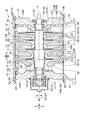
- the compressor 1 of this embodiment is provided with the casing 2, the bundle 10, and the control part 18 as shown in FIG.1 and FIG.2.
- an axial direction Da A radial direction based on the axis O is simply referred to as a radial direction Dr.
- the vertical direction Dv is defined as the vertical direction in FIG. 1 and FIG.
- the radial direction Dr and the axial direction Da perpendicular to the axis O, and the horizontal direction in FIGS. 1 and 2 is defined as a horizontal direction Dh.
- a direction around the rotor 11 around the axis O is a circumferential direction Dc.
- the casing 2 is disposed so as to cover the bundle 10 from the outer peripheral side.
- the casing 2 has a cylindrical shape with both ends opened around a central axis arranged in the same manner as an axis O of the rotor 11 described later.
- the cylindrical casing 2 includes an upper half casing 21 above the vertical direction Dv and a lower half casing 22 (see FIG. 2) below the vertical direction Dv.
- the upper half casing 21 has a cross section perpendicular to the axis O extending in the axial direction Da in a semicircular shape centering on the axis O.
- the upper half casing 21 opens downward in the vertical direction Dv so that the bundle 10 is fitted therein. Thereby, the upper half casing 21 has covered the outer peripheral surface of the bundle 10 accommodated in the inside from upper direction.
- the upper half casing 21 of the present embodiment is formed with flanges extending in the horizontal direction Dh at both ends in the circumferential direction Dc.
- the upper half casing 21 has upper half casing dividing surfaces 211 at both ends in the circumferential direction Dc.
- the upper half casing dividing surface 211 is one of the dividing surfaces when the casing 2 is divided vertically in the vertical direction Dv.
- the upper half casing dividing surface 211 is a flat surface extending in the radial direction Dr and the axial direction Da. That is, the upper half casing dividing surface 211 is a horizontal plane that faces downward in the vertical direction Dv.
- the lower half casing 22 has a cross section perpendicular to the axis O extending in the axial direction Da in a semicircular shape centering on the axis O.
- the lower half casing 22 is opened upward in the vertical direction Dv so that the bundle 10 is fitted therein. Thereby, the lower half casing 22 has covered the outer peripheral surface of the bundle 10 accommodated in the inside from the downward direction.
- flanges extending in the horizontal direction Dh are formed at both ends in the circumferential direction Dc.
- the lower half casing 22 has lower half casing dividing surfaces 221 at both ends in the circumferential direction Dc.
- the lower half casing dividing surface 221 is the other dividing surface when the casing 2 is divided vertically in the vertical direction Dv.
- the lower half casing dividing surface 221 is a flat surface extending in the radial direction Dr and the axial direction Da. That is, the lower half casing dividing surface 221 is a horizontal surface facing upward in the vertical direction Dv.
- the lower half casing 22 has a suction port 23 for supplying a process gas (fluid) to be compressed into the casing 2 and a discharge for discharging the compressed process gas from the inside of the casing 2. And a port 24.
- the bundle 10 is accommodated in the casing 2.
- the bundle 10 of the present embodiment includes a rotor 11, a bearing portion 12, a plurality of diaphragms 13, a plurality of heads 14, a head seal portion 15, a communication gap seal portion 16, and a fastening portion 17. Yes.
- the rotor 11, the bearing portion 12, the plurality of diaphragms 13, the plurality of heads 14, the head seal portion 15, the communication gap seal portion 16, and the fastening portion 17 are integrally movable.
- the rotor 11 is rotatable about the axis O.
- the rotor 11 includes a rotor shaft 111 that extends in the axial direction Da around the axis O, and a plurality of impellers 112 that rotate together with the rotor shaft 111.
- the impeller 112 is fixed to the outer peripheral surface of the rotor shaft 111.
- the impeller 112 compresses the process gas using centrifugal force by rotating together with the rotor shaft 111.
- the impeller 112 is provided in a plurality of stages in the axial direction Da with respect to the rotor shaft 111.
- the impeller 112 is a so-called open type impeller including a disk and a blade.
- the bearing portion 12 supports the rotor shaft 111 so as to be rotatable about the axis O.
- the bearing portion 12 is fixed to a head 14 described later.
- the bearing portion 12 includes a pair of journal bearings 121 provided at both ends of the rotor shaft 111 and a thrust bearing 122 provided at one end of the rotor shaft 111.
- the pair of journal bearings 121 plays a role of receiving a load in the radial direction Dr acting on the rotor shaft 111.
- These journal bearings 121 are respectively fixed to the pair of heads 14 using detachable fixing means (not shown) such as bolts.
- the thrust bearing 122 plays a role of receiving a load in the axial direction Da acting on the rotor shaft 111.
- the thrust bearing 122 is attached inside a box-shaped bearing cover 123.
- the bearing cover 123 is fixed to one head 14 using a detachable fixing means such as a bolt.
- the diaphragm 13 is disposed so as to cover the rotor 11 from the outer peripheral side.
- the diaphragm 13 has an annular shape around the axis O.
- the annular diaphragm 13 has an upper half diaphragm 131 that forms a semi-annular shape above the vertical direction Dv with respect to the axis O of the rotor 11, and a lower half diaphragm 132 that forms a semi-annular shape below.
- the upper half diaphragm 131 and the lower half diaphragm 132 are fixed by a detachable fixing means such as a bolt.
- a plurality (four in this embodiment) of the diaphragms 13 are arranged so as to be stacked in the axial direction Da.
- the plurality of diaphragms 13 have a cylindrical shape extending in the axial direction Da.
- a plurality of diaphragms 13 are fixed to each other so that a flow path to be introduced into the flow path of the impeller 112 is defined inside.
- the outer peripheral surfaces of the adjacent diaphragms 13 are fixed to each other by welding.
- welded portions 231 are formed at the corners facing the outer peripheral surface of the adjacent diaphragm 13.
- the plurality of diaphragms 13 are integrated by being fixed to each other by the welded portion 231.
- a welded groove 232 is formed in the adjacent diaphragm 13 so as to sandwich the welded part 231 from the axial direction Da.
- the weld groove 232 is recessed from the outer peripheral surfaces of the upper half diaphragm 131 and the lower half diaphragm 132 toward the inside in the radial direction Dr.
- the weld groove 232 is formed over the entire circumference in the circumferential direction Dc with respect to the outer circumferential surface of the diaphragm 13.
- the diaphragm 13 includes the suction port 236, the plurality of casing channels 235, and the discharge port 237 together with the casing 2 and the head 14 described later in order from the upstream side where the process gas flows. It is defined.
- the suction port 236 allows the process gas flowing from the outside of the casing 2 through the suction port 23 to flow into the casing flow path 235 inside the diaphragm 13.
- the suction port 236 allows the process gas to flow into the most upstream impeller 112.
- the inlet port 236 is provided with an inlet guide vane.
- the casing flow path 235 is formed in the diaphragm 13, and supplies process gas from the suction port 236 to the most upstream impeller 112, and impeller disposed downstream from the process gas discharged from the upstream impeller 112. 112, or the process gas discharged from the most downstream impeller 112 is supplied to the discharge port 237.
- the discharge port 237 discharges the process gas flowing through the inside of the diaphragm 13 to the outside of the casing 2 through the discharge port 24.
- the discharge port 237 discharges the process gas discharged from the most downstream impeller 112 to the outside.
- the pair of heads 14 are annular members, and are formed to have a size capable of closing the openings at both ends of the casing 2. Both ends of the rotor shaft 111 are inserted through the head 14.
- the suction-side head 141 disposed on one side (first side) in the axial direction Da with respect to the plurality of diaphragms 13, and the other side in the axial direction Da with respect to the plurality of diaphragms 13 ( And a discharge-side head 142 disposed on the second side.
- the suction side head 141 is disposed at a position closer to the suction port 236 than the discharge side head 142.
- the suction-side head 141 forms a suction port 236 together with the inlet wall 135 that is the diaphragm 13 disposed on the most side in the axial direction Da.
- a suction-side head exterior surface 241 that is a surface facing the one side in the axial direction Da of the suction-side head 141 faces the outside of the compressor 1.
- the suction-side head 141 is fixed using a plurality of integrated diaphragms 13 and bolt members 170. Specifically, the bolt member 170 is disposed through a groove recessed from the outer peripheral surface of the inlet wall 135.
- the inlet wall 135 and the suction-side head 141 are fixed to the upper half diaphragm 131 and the lower half diaphragm 132 by two bolt members 170 respectively.
- the fixing location by the bolt member 170 is not limited to two places, respectively, and there may be three or more places.
- the suction-side head 141 is integrated with the diaphragm 13.
- the discharge side head 142 is disposed at a position closer to the discharge port 237 than the suction side head 141.
- the discharge-side head 142 forms a discharge port 237 together with the final stage diaphragm 136 which is the diaphragm 13 disposed on the other side in the most axial direction Da.
- the discharge-side head 142 of this embodiment includes an outlet wall 145 that forms part of the discharge port 237 and a discharge-side head body 146 that is fixed to the outlet wall 145.
- the discharge-side head main body 146 is adjacent to the other side of the outlet wall portion 145 in the axial direction Da.
- a discharge-side head exterior surface 245 that faces the other side of the discharge-side head main body 146 in the axial direction Da faces the outside of the compressor 1.
- the distance in the axial direction Da from the suction-side head exterior surface 241 to the discharge-side head exterior surface 245 is approximately the same as the length of the casing 2 in the axial direction Da. That is, in this embodiment, the both ends of the casing 2 do not protrude from the suction side head exterior surface 241 and the discharge side head exterior surface 245.
- the head seal 15 seals between the outer peripheral surface of the head 14 and the inner peripheral surface of the casing 2.
- the head seal portion 15 of the first embodiment has a first head seal portion 151 provided on the suction side head 141 and a second head seal portion 152 provided on the discharge side head 142.
- first head seal portion 151 and the second head seal portion 152 have the same structure, the first head seal portion 151 will be described as an example.
- the first head seal portion 151 has an annular shape and surrounds the suction side head 141 over the entire circumference. As shown in FIG. 4, the first head seal portion 151 is an O-ring housed in a head seal mounting groove 251 formed on the outer peripheral surface of the suction side head 141. Two first head seal portions 151 are provided side by side in the axial direction Da with respect to the suction-side head 141.
- Two head seal mounting grooves 251 are formed side by side in the axial direction Da.
- the head seal mounting groove 251 is formed on the outer peripheral surface of the head 14 at a position as close as possible to the outside in the axial direction Da (on the side opposite to the side where the diaphragm 13 is disposed with respect to the head 14).
- the outside of the axial direction Da is a direction facing the outside of the compressor 1. Therefore, the outside of the suction direction head 141 in the axial direction Da is one side of the axial direction Da, and the discharge side head 142 is outside of the axial direction Da is the other side of the axial direction Da.
- the inside of the axial direction Da is a direction opposite to the outside of the axial direction Da and is a direction facing the center position of the axial direction Da of the bundle 10 in the compressor 1. Therefore, the inside of the suction-side head 141 in the axial direction Da is the other side of the axial direction Da, and the inside of the discharge-side head 142 in the axial direction Da is one side of the axial direction Da.
- the head seal mounting groove 251 is formed at a position close to the suction-side head exterior surface 241 that is close to one side of the axial direction Da in the suction-side head 141. Further, the head seal mounting groove 251 is formed at a position close to the discharge-side head exterior surface 245 that is a position close to the other side in the axial direction Da in the discharge-side head main body 146.
- the head seal mounting groove 251 may have the same shape as a gap seal mounting groove 261 described later.
- the communication gap seal 16 seals the communication gap C formed between the outer peripheral surface of the diaphragm 13 and the inner peripheral surface of the casing 2.
- the communication gap C is formed between the outer peripheral surface of the diaphragm 13 and the inner peripheral surface of the casing 2 in a state where the bundle 10 is accommodated in the casing 2.
- the communication gap C is an annular space extending in the axial direction Da so as to communicate the suction port 236 and the discharge port 237.
- the communication gap seal portion 16 of the present embodiment is an O-ring accommodated in a gap seal mounting groove 261 formed on the outer peripheral surface of the inlet wall 135. Only one communication gap seal portion 16 is provided for the communication gap C. Specifically, the gap seal mounting groove 261 is formed at a position close to the suction port 236 on the outer peripheral surface of the inlet wall 135 (a position close to one side in the axial direction Da as much as possible).
- the communication gap seal portion 16 has an annular shape and is formed over the entire circumference of the combined upper half diaphragm 131 and lower half diaphragm 132.
- the gap seal mounting groove 261 has a horizontal direction that is 90 degrees different in the circumferential direction Dc from the upper vertex of the vertical direction Dv in the upper half diaphragm 131 and the lower vertex of the vertical direction Dv in the lower half diaphragm 132. It forms so that it may become deep as it goes to the position of the both ends of Dh.
- the gap seal mounting groove 261 is configured such that the communication gap seal portion 16 has a radial direction Dr rather than the outer peripheral surface of the diaphragm 13 at the upper vertex of the vertical direction Dv in the upper half diaphragm 131 and the lower vertex of the vertical direction Dv in the lower half diaphragm 132. It is formed with a depth that protrudes outside.
- the gap seal mounting groove 261 is formed at a depth such that the communication gap seal portion 16 does not protrude from the outer peripheral surface of the diaphragm 13 at both ends in the horizontal direction Dh.
- the fastening part 17 fixes the discharge side head 142 and the last stage diaphragm 136 so that attachment or detachment is possible.
- a plurality of fastening portions 17 are provided evenly in the circumferential direction Dc around the axis O with respect to the ejection-side head 142.
- the fastening portion 17 of the present embodiment includes a fixed hole 171, a bolt mounting groove 172, a fastening through hole 173, a bolt member 174, and an elastic member 175.
- the fixed hole 171 includes a fixed screw hole 271 formed in the discharge-side head main body 146 and a fixed through-hole 272 formed in the outlet wall portion 145.
- the fixed screw hole 271 is formed in the discharge-side head main body inner side surface 244 which is a flat surface facing one side in the axial direction Da in the discharge-side head main body 146.
- the fixed screw hole 271 is a screw hole having a female screw inside, and the bolt member 174 can be fixed thereto.
- the fixed through hole 272 penetrates the outlet wall 145 in the axial direction Da at the same position as the fixed screw hole 271 when viewed from the axial direction Da.
- the fixed through-hole 272 passes through the outlet inner surface 242 facing the one side in the axial direction Da and the outlet outer surface 243 facing the other side of the axial direction Da in the outlet wall portion 145.
- the outlet inner surface 242 is a flat surface that comes into contact with the final stage diaphragm 136 when the discharge-side head 142 is fixed to the final stage diaphragm 136.
- the outlet outer surface 243 is a flat surface that comes into contact with the discharge-side head main body 146 when the outlet wall 145 is fixed to the discharge-side head main body 146.
- the outer peripheral surface of the final stage diaphragm 136 is recessed with a rectangular cross section.
- the bolt mounting groove 172 is formed such that the length in the axial direction Da is longer than the length of the bolt member 174.
- a plurality of bolt mounting grooves 172 are formed apart from each other in the circumferential direction Dc with respect to the outer peripheral surface of the final stage diaphragm 136.
- the fastening through hole 173 is formed in the final stage diaphragm 136.
- the fastening through hole 173 is formed at a position overlapping the fixed screw hole 271 and the fixed through hole 272 when viewed from the axial direction Da.
- the fastening through hole 173 passes through the groove inner side surface 273 facing one side in the axial direction Da and the final stage diaphragm contact surface 234 facing the other side in the axial direction Da.
- the groove inner side surface 273 is a part of a plane that forms the bolt mounting groove 172.
- the final stage diaphragm contact surface 234 is a plane that contacts the outlet inner side surface 242 when the final stage diaphragm 136 is fixed to the outlet wall 145.
- the bolt member 174 has a shaft portion 274 having a male screw on the outer peripheral surface, and a head portion 275 formed at the end of the shaft portion 274.
- the shaft portion 274 has a tip fixed to the fixed screw hole 271 while being inserted into the fastening through hole 173 and the fixed through hole 272.
- the head 275 is formed in a size that can be accommodated in the bolt mounting groove 172. That is, the head 275 is disposed in the bolt mounting groove 172 with the shaft portion 274 fixed to the fixed screw hole 271.
- the elastic member 175 is a plurality of disc spring washers disposed between the head 275 and the groove inner side surface 273. A plurality of elastic members 175 are stacked. The elastic member 175 is sandwiched between the surface facing the other side of the axial direction Da of the head 275 and the inner surface 273 of the groove in a state where the shaft portion 274 is inserted.
- the restricting portion 18 is provided on at least one of the casing 2 and the head 14.
- the restricting portion 18 restricts the position of the head 14 in the axial direction Da with respect to the casing 2.
- the restricting portion 18 of the first embodiment is provided over both the casing 2 and the head 14.
- the restricting portion 18 is provided for each of the suction side head 141 and the discharge side head 142.
- the restricting portion 18 is formed on the fitting recess 181 formed on the inner peripheral surface of the casing 2, and on the outer peripheral surfaces of the suction side head 141 and the discharge side head main body 146. It has the fitting recessed part 181 and the fitting convex part 182 fitted.
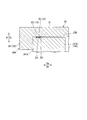
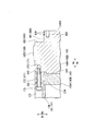
- FIG. 4 is an enlarged view of a main part for explaining the restricting portion 18 provided between the suction-side head 141 and the upper half casing 21.
- the restricting portions 18 are provided corresponding to the suction side head 141 and the discharge side head 142, respectively.
- the restricting portion 18 around the suction side head 141 will be described as an example with reference to FIG.
- the fitting recess 181 has a rectangular cross section from the inner peripheral surface of the casing 2 and is recessed over the entire periphery. Two fitting recesses 181 are formed apart in the axial direction Da corresponding to the position where the suction-side head 141 is disposed. The fitting recess 181 is formed in each of the upper half casing 21 and the lower half casing 22.
- the fitting convex part 182 has a rectangular cross section and protrudes from the outer peripheral surface of the suction side head 141 over the entire circumference.
- the fitting convex part 182 is formed inside the axial direction Da with respect to the head seal mounting groove 251.
- Two fitting convex portions 182 are formed side by side in the axial direction Da with respect to the suction-side head 141.
- the compressor manufacturing method S ⁇ b> 1 of the present embodiment includes a preparation step S ⁇ b> 10, a bundle arrangement step S ⁇ b> 30, and an upper half casing arrangement step S ⁇ b> 40.
- preparation step S10 parts necessary for manufacturing the compressor 1 are prepared.
- preparatory process S10 of 1st embodiment casing preparatory process S11 and bundle preparatory process S12 are implemented simultaneously.
- the upper half casing 21 and the lower half casing 22 in which the fitting recess 181 is formed are manufactured and prepared.
- the preparation step S ⁇ b> 10 the rotor 11, the bearing portion 12, the upper half diaphragm 131, the lower half diaphragm 132, the suction side head 141, the discharge side head 142, the communication gap seal portion 16, and the fastening portion 17. are prepared by being manufactured.
- the diaphragm 13 is formed in an annular shape by fixing the upper half diaphragm 131 on the lower half diaphragm 132 by a fixing means such as a bolt with the rotor 11 disposed therein. Thereafter, the outer peripheral surfaces of the adjacent diaphragms 13 are welded to form a welded portion 231. Thereby, the plurality of diaphragms 13 are integrated.
- a communication gap seal portion 16 is attached to the outer peripheral surface of the integrated diaphragm 13.
- the head seal portion 15 is attached to the suction side head 141 and the discharge side head 142 in which the fitting convex portion 182 is formed.
- the bearing portion 12 is fixed to the suction side head 141 and the discharge side head 142. Thereafter, the suction-side head 141 is fixed to the diaphragm 13 by the bolt member 170. Further, the discharge-side head 142 is fixed to the diaphragm 13 by the fastening portion 17. By these, the bundle 10 integrated as one component is prepared.
- the bundle 10 is arranged from above in the vertical direction Dv with respect to the lower half casing 22, as shown in FIG.
- An eyebolt 501 is fixed to the outer peripheral surface of the bundle 10 in advance.
- the eyebolts 501 are attached to the outer peripheral surface of the suction-side head 141 at two locations and to the outer peripheral surface of the discharge-side head 142, respectively.
- the eyebolt 501 is attached at a position that is 45 degrees different from the upper end in the vertical direction Dv in the circumferential direction Dc. As shown in FIG.
- a plurality of rod-shaped guide bars 502 are attached to the lower half casing 22 so as to extend upward from the lower half casing dividing surface 221 in the vertical direction Dv.
- a guide plate 503 guided along the guide rod 502 is attached to the bundle 10 by inserting the guide rod 502.
- the guide plate 503 is attached to the outer peripheral surface of the diaphragm 13 corresponding to the position where the guide rod 502 is provided.
- the wire 504 is fixed to the eyebolt 501.
- the bundle 10 is once lifted above the vertical direction Dv. Thereafter, the horizontal position of the bundle 10 is adjusted so that the guide bar 502 is inserted into the guide plate 503, and the bundle 10 is lowered. As a result, the bundle 10 descends along the guide bar 502.
- the bundle 10 When the bundle 10 is lowered to the vicinity of the lower half casing 22, the guide plates 503 are respectively removed from the bundle 10, and the pair of guide rods 502 are respectively removed from the lower half casing 22. Thereafter, the bundle 10 is lowered to the inner peripheral side of the lower half casing 22.
- the bundle 10 When the bundle 10 is arranged inside the lower half casing 22, the fitting convex portion 182 formed on the suction side head 141 and the discharge side head with respect to the fitting concave portion 181 formed on the lower half casing 22.
- the bundle 10 is lowered so that the fitting convex part 182 formed in the main body 146 fits.
- a communication gap C is formed between the outer peripheral surface of the lower half diaphragm 132 and the inner peripheral surface of the lower half casing 22.
- the communication gap C is sealed by the communication gap seal portion 16 contacting the inner peripheral surface of the lower half casing 22.
- the upper half casing arrangement step S40 is performed after the bundle arrangement step S30.
- the upper half casing 21 is arranged from above in the vertical direction Dv with respect to the bundle 10 fitted in the lower half casing 22.
- a wire 504 is fixed to the flange of the upper half casing 21. By winding the wire 504 using a crane, the upper half casing 21 is once lifted above the vertical direction Dv. Thereafter, the upper half casing 21 is lowered above the bundle 10.
- the horizontal position is adjusted so that the bundle 10 is accommodated on the inner peripheral side of the upper half casing 21.
- the fitting convex portion 182 formed on the suction side head 141 and the discharge side head with respect to the fitting concave portion 181 formed on the upper half casing 21.
- the upper half casing 21 is lowered so that the fitting convex part 182 formed in the main body 146 fits.
- the positions of the suction-side head 141 and the discharge-side head main body 146 in the axial direction Da are restricted with respect to the upper half casing 21.
- a communication gap C is formed between the outer peripheral surface of the upper half diaphragm 131 and the inner peripheral surface of the upper half casing 21.
- the communication gap C is sealed by the communication gap seal portion 16 contacting the inner peripheral surface of the upper half casing 21.
- the upper half casing 21 and the lower half casing 22 are fixed by the fixing means while the upper half casing dividing surface 211 is in contact with the lower half casing dividing surface 221, and the compressor 1 is completed.
- the suction port 236 and the discharge port 237 are communicated with each other, formed between the outer peripheral surface of the diaphragm 13 and the inner peripheral surface of the casing 2.
- the communication gap C is sealed by the communication gap seal portion 16.
- the communication gap C is formed between the outer peripheral surface of the diaphragm 13 and the inner peripheral surface of the casing 2, thereby preventing interference and the like when assembling the casing 2 and the bundle 10 having the upper and lower split structures. Can be improved.
- the communication gap C since the communication gap C is sealed, it is possible to prevent the high-pressure process gas supplied to the discharge port 237 from leaking from the suction port 236 through the communication gap C. Thereby, the leak between the outer peripheral surfaces of the diaphragm 13 can be reduced.
- the communication gap seal portion 16 is provided only at one place on the outer peripheral surface of the inlet wall 135 in the communication gap C. Therefore, the high-pressure process gas that has flowed into the communication gap C from the discharge port 237 flows into a position where the communication gap seal portion 16 is provided. Therefore, the pressure around the outer peripheral surface of all the diaphragms 13 becomes high. Therefore, surface pressure is applied to the dividing surface of the casing 2 having the upper and lower divided structures, and the sealing performance of each diaphragm 13 can be improved.
- the restricting portion 18 a fitting concave portion 181 formed on the inner peripheral surface of the casing 2 and a fitting convex portion 182 formed on the outer peripheral surfaces of the suction side head 141 and the discharge side head main body 146 are provided. Yes. Therefore, the position of the head 14 in the axial direction Da relative to the casing 2 can be regulated with a simple structure that merely forms a concavo-convex shape. Further, the restricting portion 18 that restricts the position of the head 14 in the axial direction Da with respect to the casing 2 is directly formed as a part of the casing 2 and the head 14, not a separate member.
- the structure that restricts the position of the bundle 10 and the casing 2 in the axial direction Da is only the fitting recess 181 and the fitting projection 182, and is not provided in the diaphragm 13. For this reason, the number of parts to be assembled and the positioning locations in the axial direction Da are reduced, and adjustment when assembling the casing 2 and the bundle 10 is facilitated. As a result, the assemblability can be further improved.
- Both ends of the diaphragm 13 in the horizontal direction Dh are close to the dividing surface of the casing 2. Therefore, when the protruding amount of the communication gap seal portion 16 increases at both ends in the horizontal direction Dh, when the upper half casing 21 is attached to the lower half casing 22, the O-ring is sandwiched between the split surfaces or rubbed against the edges. May cause damage.
- the gap seal mounting groove 261 is formed so as to become deeper toward both ends in the horizontal direction Dh. Therefore, the communication gap seal portion 16 fitted in the gap seal mounting groove 261 moves from the outer peripheral surface of the diaphragm 13 toward the both ends in the horizontal direction Dh from the upper vertex in the vertical direction Dv or the lower vertex in the vertical direction Dv.
- the amount of protrusion is reduced. Thereby, damage to the O-ring that is the communication gap seal portion 16 when the upper half casing 21 is attached to the lower half casing 22 can be reduced.
- the amount of protrusion of the communication gap seal portion 16 is the smallest at both ends in the horizontal direction Dh. Therefore, damage to the communication gap seal portion 16 when the upper half casing 21 is attached to the lower half casing 22 can be more effectively reduced.
- the process gas that has been compressed and becomes high temperature and high pressure flows through the vicinity of the discharge port 237, whereby the final stage diaphragm 136 and the outlet wall portion 145 are heated, and the thermal extension in the axial direction Da is increased. May occur.
- the final stage diaphragm 136 and the outlet wall portion 145 extend in the axial direction Da between the tip and the head 275.
- a pulling force in the axial direction Da acts on the boundary between the shaft portion 274 and the head portion 275 of the bolt member 174.
- the fastening portion 17 is not limited to being used for fixing the discharge side head 142 and the final stage diaphragm 136.
- the fastening portion 17 may be used for fixing the suction side head 141 and the inlet wall 135.
- the elastic member 175 is not limited to being a disc spring washer.
- the elastic member 175 may be a rubber material or a spring member.
- the fixed hole 171 is not limited to the structure formed in the discharge-side head 142.
- the fixed hole 171 may be formed in the final stage diaphragm 136.
- the fixing of the adjacent diaphragms 13 is not limited to welding, and other fixing means may be used. In the present embodiment, four diaphragms 13 are provided. However, the number of diaphragms 13 is not limited to this, and the design can be appropriately changed according to the number of stages of the impeller 112.
- the communication gap seal portion 16 is not limited to being provided on the outer peripheral surface of the diaphragm 13 as a part of the bundle 10.
- the communication gap seal portion 16 may be provided on the casing 2 side or may be provided as a separate member as long as the communication gap C can be sealed.
- the restricting portion 18A is provided in the casing 2A.
- the upper half casing 21 ⁇ / b> A has an upper half casing body 31 and an upper half protrusion 32.
- the lower half casing 22 ⁇ / b> A includes a lower half casing body 35 and a lower half protruding portion 36.
- the upper half protruding portion 32 and the lower half protruding portion 36 constitute a restricting portion 18A in the present embodiment. That is, the restricting portion 18A of the second embodiment is formed only on the casing 2A.
- the upper half casing body 31 has a cross section orthogonal to the axis O extending in the axial direction Da in a semicircular shape centering on the axis O.
- the upper half casing body 31 is opened facing downward in the vertical direction Dv so that the bundle 10 is fitted therein. Thereby, the upper half casing main body 31 has covered the upper side of the outer peripheral surface of the bundle 10 accommodated in the inside.
- the upper half casing body 31 has upper half casing dividing surfaces 211 at both ends in the circumferential direction Dc. That is, the upper half casing body 31 has the same shape as the upper half casing 21 of the first embodiment.
- the lower half casing body 35 has a cross section perpendicular to the axis O extending in the axial direction Da in a semicircular shape centering on the axis O.
- the lower half casing body 35 is opened upward in the vertical direction Dv so that the bundle 10 is fitted therein. Thereby, the lower half casing main body 35 has covered the lower side of the outer peripheral surface of the bundle 10 accommodated in the inside.
- the lower half casing body 35 has lower half casing dividing surfaces 221 at both ends in the circumferential direction Dc. That is, the lower half casing body 35 has the same shape as the lower half casing 22 of the first embodiment. Therefore, the lower half casing 22A and the upper half casing 21A are combined to form a cylindrical shape having both ends opened.
- the upper half protrusions 32 are respectively formed at both ends of the upper half casing body 31 in the axial direction Da.
- the upper half projecting portion 32 projects from the upper half casing body 31 toward the inside in the radial direction Dr so as to form a semi-annular shape.
- the upper half projecting portion 32 includes a first upper half projecting portion 321 provided on the outer side in the axial direction Da with respect to the suction side head 141A, and an outer side in the axial direction Da with respect to the discharge side head 142A. And a second upper half projecting portion 322 provided on the head.
- the first upper half protrusion 321 is formed at one end of the upper half casing body 31 in the axial direction Da. As shown in FIG. 12, the surface of the first upper half protrusion 321 facing the other side in the axial direction Da is in contact with the suction-side head exterior surface 241A that is the end surface facing the outside of the axial direction Da in the suction-side head 141A. ing.
- the second upper half protrusion 322 is formed at the other end of the upper half casing body 31 in the axial direction Da.
- the surface of the second upper half projecting portion 322 facing one side in the axial direction Da is in contact with the discharge-side head exterior surface 245A, which is the end surface facing the outside of the axial direction Da in the discharge-side head main body 146A.
- the lower half protrusions 36 are respectively formed at both ends of the lower half casing body 35 in the axial direction Da.
- the lower half projecting portion 36 projects from the lower half casing body 35 toward the inside in the radial direction Dr so as to form a semi-annular shape.
- the lower half protrusion 36 includes a first lower half protrusion 361 provided on the outer side in the axial direction Da with respect to the suction-side head 141A, and an outer side in the axial direction Da with respect to the discharge-side head 142A. And a second lower half projecting portion 362 provided on the second lower half.
- the first lower half protrusion 361 is formed at one end of the lower half casing body 35 in the axial direction Da.
- the surface of the first lower half projecting portion 361 facing the other side in the axial direction Da is in contact with the suction-side head exterior surface 241A that is the end surface facing the outside of the axial direction Da in the suction-side head 141A.
- the surface of the first lower half projecting portion 361 facing the other side in the axial direction Da is formed at the same position as the surface of the first upper half projecting portion 321 facing the other side of the axial direction Da in the axial direction Da. .
- the second lower half protrusion 362 is formed at the other end of the lower half casing body 35 in the axial direction Da.
- the surface of the second lower half protrusion 362 facing the one side in the axial direction Da is in contact with the discharge-side head exterior surface 245A, which is the end surface facing the outside of the axial direction Da in the discharge-side head 142A.
- the surface of the second lower half projecting portion 362 facing one side in the axial direction Da is formed at the same position as the surface of the second upper half projecting portion 322 facing one side of the axial direction Da in the axial direction Da. .
- the fitting convex part 182 is not formed in the head 14A of 2nd embodiment.
- a gap expanding recess 370 is formed on the inner side in the axial direction Da from the head seal mounting groove 251 on the outer peripheral surface of the head 14A (on the side where the diaphragm 13 is disposed with respect to the head 14A).
- the gap expanding recess 370 is recessed from the outer circumferential surface of the head 14A so as to increase the gap with the inner circumferential surface of the casing 2A.
- the position of Da can be regulated. Since the upper half protrusion 32 and the lower half protrusion 36 are located outside the compressor 1A, it is difficult to be limited in space. Therefore, even if the thrust force generated in the bundle 10 is large depending on the type of process gas to be compressed, the upper half protrusion 32 and the lower half protrusion 36 can be enlarged in accordance with the force generated in the bundle 10. Thereby, the position of the bundle 10 with respect to the casing 2A can be stably held. In addition, it can be confirmed that the position of the bundle 10 with respect to the casing 2A is regulated at a position that can be viewed from the outside.
- both ends of the casing 2B are formed to protrude outward in the axial direction Da from the suction side head 141B and the discharge side head 142B. That is, the length in the axial direction Da of the casing 2B of the third embodiment is longer than the distance in the axial direction Da from the suction-side head exterior surface 241B to the discharge-side head exterior surface 245B.
- the regulating portion 18B of the third embodiment has other members in addition to the casing 2B and the head 14B.
- the restriction portion 18 ⁇ / b> B includes a restriction accommodation recess 410, a head restriction accommodation groove 420, a first restriction member 430, and a second restriction member 440.
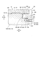
- FIG. 14 is an enlarged view of a main part for explaining the restricting portion 18B provided between the suction-side head 141B and the upper half casing 21B.
- the restricting portion 18B of the third embodiment is provided corresponding to each of the suction side head 141B and the discharge side head 142B.
- the restricting portion 18B around the suction side head 141B will be described as an example with reference to FIG. I will explain.
- the regulation accommodation recessed part 410 is formed in the part protruded to the outer side of the axial direction Da rather than the suction side head 141B in the edge part of the casing 2B.
- the restriction accommodating recess 410 is recessed with a rectangular cross section from the inner peripheral surface of the casing 2B so that a part thereof is located outside the axial direction Da with respect to the suction-side head 141B.
- the regulation accommodation recess 410 includes a regulation accommodation recess bottom surface 411 facing the inside in the radial direction Dr, a regulation accommodation recess first surface 412 facing the inside in the axial direction Da, and a regulation accommodation recess second surface 413 facing the outside in the axial direction Da. It consists of and.
- the regulation accommodating recess bottom surface 411 is a surface parallel to the inner peripheral surface of the casing 2B.
- the regulation accommodation recessed part 1st surface 412 is a plane which connects the inner peripheral surface of the casing 2B, and the short side outside the axial direction Da in the regulation accommodation recessed part bottom face 411.
- the regulation accommodation recessed part 2nd surface 413 is a plane which connects the inner peripheral surface of the casing 2B, and the short side inside the axial direction Da in the regulation accommodation recessed part bottom face 411.
- the head regulation accommodation groove 420 is formed at a corner portion formed by the outer peripheral surface of the suction side head 141B and the suction side head exterior surface 241B (surface facing the outside in the axial direction Da).
- the head regulation accommodation groove 420 is formed outside the head seal attachment groove 251 in the axial direction Da.
- the head regulation accommodation groove 420 is composed of a regulation accommodation groove first surface 421 facing the outside in the radial direction Dr and a regulation accommodation groove second surface 422 facing the outside in the axial direction Da.
- the regulation accommodating groove first surface 421 is a surface parallel to the outer peripheral surface of the suction side head 141B, and is connected to the suction side head exterior surface 241B.
- the restriction accommodating groove second surface 422 is a plane parallel to the suction side head exterior surface 241B, and is a surface connecting the outer peripheral surface of the suction side head 141B and the restriction accommodating groove first surface 421.
- the first regulating member 430 is a member that regulates the position of the suction-side head 141B in the axial direction Da relative to the casing 2B by being housed in the regulating housing recess 410 together with the second regulating member 440.
- the first regulating member 430 has an L-shaped cross section. Specifically, in the first restricting member 430, a first accommodating portion 431 accommodated in the restricting accommodating recess 410 and a second accommodating portion 432 accommodated in the head restricting accommodating groove 420 are integrally formed.
- the first accommodating portion 431 has a rectangular shape.
- the second housing portion 432 is formed to project from the first housing portion 431 in a rectangular shape toward the inner side in the axial direction.
- the second restriction member 440 is accommodated in the restriction accommodation recess 410 in a state adjacent to the first restriction member 430 outside the first restriction member 430 in the axial direction Da.
- the second regulating member 440 has a rectangular shape.
- the first restricting member 430 moves inward in the axial direction Da while the first accommodating portion 431 is inserted into the restricting accommodating recess 410. Then, the second storage portion 432 is inserted into the head restriction storage groove 420. Thereafter, the second restricting member 440 is press-fitted into the restricting housing recess 410 outside the first restricting member 430 in the axial direction Da. As a result, the first restricting member 430 and the second restricting member 440 are in contact with each other while being accommodated in the restricting accommodating recess 410 and the head restricting accommodating groove 420.
- the second housing portion 432 comes into contact with the regulation housing groove second surface 422, and the second regulation member 440 comes into contact with the regulation housing recess first surface 412.
- the first restriction member 430 and the second restriction member 440 are sandwiched between the restriction accommodation recess first surface 412 and the restriction accommodation groove second surface 422 and cannot be removed.
- the first restriction member 430 and the second restriction member 440 are accommodated in the restriction accommodation recess 410 and the head restriction accommodation groove 420. Thereby, the position of the axial direction Da of the suction-side head 141B and the discharge-side head 142B with respect to the casing 2B can be regulated from the outside of the compressor 1B. Furthermore, the first regulating member 430 and the second regulating member 440 can be attached from the outside after the upper half casing 21B is installed on the bundle 10.
- ⁇ 4th embodiment >> Next, a fourth embodiment of the compressor of the present invention will be described with reference to FIGS. 15 to 17.
- the compressor 1C shown in the fourth embodiment is different from the first embodiment in the configuration of the head seal portion. Therefore, in the description of the fourth embodiment, the same parts as those in the first embodiment to the third embodiment are denoted by the same reference numerals and redundant description is omitted.
- the compressor 1C of the fourth embodiment includes a head seal portion 15C having a separate member for sealing between the head 14C and the casing 2C.
- the head seal portion 15 ⁇ / b> C of the fourth embodiment includes a seal ring 600, a seal ring fixing hole 650, a ring insertion groove 660, and an inner ring seal portion 670.
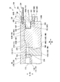
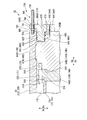
- FIG. 16 is an enlarged view of a main part for explaining the head seal portion 15C provided between the discharge-side head 142C and the upper half casing 21C.
- the head seal portion 15C of the fourth embodiment is provided corresponding to each of the suction side head 141C and the discharge side head 142C.
- the head seal portion 15C around the discharge side head 142C will be described as an example with reference to FIG. Will be described.
- the seal ring 600 is detachable from the outer side in the axial direction Da with respect to the discharge-side head main body 146C. That is, the seal ring 600 is movable in the axial direction Da from the outside of the discharge-side head main body 146C and the casing 2C.
- the seal ring 600 is attached from the outside after the casing 2 ⁇ / b> C is attached to the bundle 10.
- the seal ring 600 is an annular member centered on the axis O.
- the seal ring 600 according to the present embodiment includes a ring main body 610, a ring insertion portion 620, an outer ring seal portion 630, and a ring fixing member 640.
- the seal ring 600 is fixed to the seal ring fixing hole 650.
- the seal ring fixing hole 650 is formed in the discharge-side head exterior surface 245C.
- the seal ring fixing hole 650 is a screw hole having a female screw inside.
- the ring insertion portion 620 can be inserted.
- the ring insertion groove 660 is formed at a corner formed by the outer peripheral surface of the discharge-side head main body 146C and the discharge-side head exterior surface 245C (surface facing the outside in the axial direction Da).
- the ring insertion groove 660 is recessed from the outer peripheral surface of the discharge-side head exterior surface 245C and the discharge-side head main body 146C in a rectangular shape.
- the ring insertion groove 660 forms a space in which the ring insertion portion 620 can be inserted between the inner peripheral surface of the casing 2C.
- the ring insertion groove 660 is formed outside the fitting protrusion 182 in the axial direction Da.
- the ring insertion groove 660 is formed outside the seal ring fixing hole 650 in the radial direction Dr.
- the ring insertion groove 660 includes a ring insertion groove first surface 661 facing the outside in the radial direction Dr and a ring insertion groove second surface 662 facing the outside in the axial direction Da.
- the ring insertion groove first surface 661 is a surface parallel to the outer peripheral surface of the discharge-side head main body 146C and is connected to the discharge-side head exterior surface 245C.
- the ring insertion groove second surface 662 is a plane parallel to the discharge-side head exterior surface 245C, and is a surface connecting the outer peripheral surface of the discharge-side head main body 146C and the ring insertion groove first surface 661.
- the inner ring seal portion 670 can seal between the inner peripheral surface of the ring insertion portion 620 and the ring insertion groove first surface 661.
- the inner ring seal portion 670 has an annular shape and surrounds the discharge-side head main body 146C over the entire circumference.
- the inner ring seal portion 670 of this embodiment is an O-ring accommodated in an inner attachment groove 671 formed in the ring insertion groove first surface 661.
- Two inner ring seal portions 670 are provided side by side in the axial direction Da with respect to the ring insertion groove first surface 661.
- Two inner mounting grooves 671 are formed side by side in the axial direction Da.
- the inner mounting groove 671 is formed at a position as close as possible to the outer side in the axial direction Da on the ring insertion groove first surface 661.
- the ring body 610 has a cross-sectional plate shape and is formed in an annular shape centering on the axis O.
- the ring insertion part 620 protrudes from the ring main body 610 over the entire circumference with a rectangular cross section. That is, the ring insertion portion 620 protrudes from the ring body 610 in an annular shape.
- the ring insertion portion 620 has a shape that can be inserted into the ring insertion groove 660.
- the amount of protrusion of the ring insertion portion 620 from the ring body 610 is greater than the depth of the ring insertion groove 660 in the axial direction Da (the distance in the axial direction Da between the discharge-side head exterior surface 245C and the ring insertion groove second surface 662). It has been shortened.
- the surface on the side where the ring insertion portion 620 protrudes is cut out outside the radial direction Dr from the position where the ring insertion portion 620 protrudes.
- the ring body 610 has an inner thickness in the radial direction Dr with respect to a position where the ring insertion portion 620 protrudes, and a thickness outside the radial direction Dr with respect to a position where the ring insertion portion 620 protrudes. And thick.
- a ring body through-hole 611 is formed in the ring body 610.
- the ring main body through hole 611 is formed at a position overlapping the seal ring fixing hole 650 when viewed from the axial direction Da in a state where the ring insertion portion 620 is inserted into the ring insertion groove 660.
- the outer ring seal portion 630 can seal between the outer peripheral surface of the ring insertion portion 620 and the inner peripheral surface of the casing 2C.
- the outer ring seal portion 630 has an annular shape and surrounds the ring insertion portion 620 over the entire circumference.
- the outer ring seal portion 630 of this embodiment is an O-ring accommodated in an outer mounting groove 631 formed on the outer peripheral surface of the ring insertion portion 620.
- Two outer ring seal portions 630 are provided side by side in the axial direction Da with respect to the outer peripheral surface of the ring insertion portion 620.
- Two outer mounting grooves 631 are formed side by side in the axial direction Da.
- the outer mounting groove 631 is formed at a position that is disposed on the inner side in the axial direction Da than the inner mounting groove 671 in a state where the ring insertion portion 620 is inserted into the ring insertion groove 660.
- the ring fixing member 640 is a bolt having a ring fixing shaft portion 641 having an external thread on the outer peripheral surface and a ring fixing head portion 642 formed at the end of the ring fixing shaft portion 641.
- the ring fixing shaft portion 641 has a tip fixed to the seal ring fixing hole 650 while being inserted into the ring body through-hole 611.
- the ring fixing head 642 is disposed outside the ring body 610 in the axial direction Da.
- an insertion gap enlarged diameter portion 680 is formed to increase the distance between the outer peripheral surface of the ring insertion portion 620 and the inner peripheral surface of the casing 2C at a position shifted outward in the axial direction Da with respect to the outer ring seal portion 630. Yes. Specifically, the insertion gap enlarged diameter portion 680 is formed at the end of the casing 2 ⁇ / b> C that is outside the outer ring seal portion 630 in the axial direction Da. The insertion gap enlarged diameter portion 680 is recessed from the inner peripheral surface of the casing 2C so as to increase the gap between the outer peripheral surface of the ring insertion portion 620 and the inner peripheral surface of the casing 2C.
- the insertion gap diameter is increased.
- the part 680 widens the gap with the outer peripheral surface of the ring insertion part 620 to 1.0 mm or more.
- the insertion gap enlarged diameter portion 680 is formed over the entire circumference at both ends in the axial direction Da of the casing 2C.
- the compressor manufacturing method S14 of the present embodiment includes a preparation step S104, a bundle arrangement step S30, an upper half casing arrangement step S40, and a head seal portion movement step S60.
- a preparation step S104 a preparation step S104
- a bundle arrangement step S30 a bundle arrangement step S30
- an upper half casing arrangement step S40 a head seal portion movement step S60.
- the casing preparatory step S114, the bundle preparatory step S124, and the head seal portion preparatory step S50 are performed simultaneously.
- the upper half casing 21C and the lower half casing 22C are prepared. At that time, insertion gap enlarged diameter portions 680 are respectively formed at both ends of the upper half casing 21C and the lower half casing 22C in the axial direction Da.
- the rotor 11, the bearing portion 12, the upper half diaphragm 131, the lower half diaphragm 132, the suction side head 141C, the discharge side head 142C, the communication gap seal portion 16, and the fastening portion 17 are provided.
- the seal ring 600 are prepared, for example.
- the suction side head 141C and the discharge side head 142C are formed with a ring insertion groove 660 and attached with an inner ring seal portion 670.
- the head seal part moving step S60 is performed after the upper half casing arranging step S40.
- the seal ring 600 is attached to the suction side head 141C and the discharge side head 142C from the outside, and the ring insertion portion 620 is connected to the outer peripheral surface of the suction side head 141C and the inner peripheral surface of the casing 2C. Or between the outer peripheral surface of the discharge-side head 142C and the inner peripheral surface of the casing 2C.
- the ring insertion portion 620 is inserted into the ring insertion groove 660 from the outside in the axial direction Da, and the ring main body 610 is fixed to the suction-side head 141C and the discharge-side head 142C by the ring fixing member 640. .
- the inner ring seal part 670 accommodated in the inner attachment groove 671 comes into contact with the inner peripheral surface of the ring insertion part 620.
- the outer ring seal portion 630 housed in the outer mounting groove 631 comes into contact with the inner peripheral surface of the casing 2C.
- the seal ring 600 is attached after the bundle 10 and the casing 2C are assembled. Thereby, it is possible to seal between the suction side head 141C and the discharge side head 142C and the casing 2C. Therefore, before the bundle 10 and the casing 2C are assembled, the outer ring seal portion 630 is not provided, and the inner ring seal portion 670 is a ring that is recessed from the outer peripheral surfaces of the suction side head 141C and the discharge side head 142C. It is provided in the insertion groove 660.
- the seal ring 600 is detachable from the outside, damage to the outer ring seal portion 630 and the inner ring seal portion 670 can be reliably prevented. Thereby, the sealing performance between the head 14C and the casing 2C can be secured more stably.
- insertion gap enlarged diameter portions 680 are formed at both ends of the casing 2C. Thereby, the clearance gap between the outer peripheral surface of the ring insertion groove 660 and the inner peripheral surface of the casing 2C becomes large. As a result, when the ring insertion portion 620 is inserted into the ring insertion groove 660, damage caused by the outer ring seal portion 630 rubbing against the inner peripheral surface of the casing 2C can be reduced.
- outer ring seal portion 630 and the inner ring seal portion 670 are each provided in duplicate in the axial direction Da. Thereby, the sealing performance between the head 14C and the casing 2C can be improved.
- the seal ring 600 is not limited to a structure that is fixed only to the head 14C as in the fourth embodiment.
- the seal ring 600 may be a structure that is fixed only to the casing 2C, or may be a structure that is fixed to the head 14C and the casing 2C.
- the ring insertion groove 660 is not limited to being formed only in the head 14C.
- the ring insertion groove 660 may be formed only in the casing 2C, or may be formed across the head 14C and the casing 2C. Further, if a space in which the ring insertion portion 620 can be inserted is formed between the head 14C and the casing 2C, the ring insertion groove 660 may not be formed.
- the insertion gap enlarged diameter portion 680 is not limited to being provided only on the outer ring seal portion 630 side.
- the insertion gap enlarged diameter portion 680 may be formed on the inner ring seal portion 670 side.
- the insertion gap enlarged diameter portion 680 is formed at, for example, a corner portion between the ring insertion groove first surface 661 and the discharge-side head exterior surface 245C.
- the inner ring seal portion 670 is not limited to being attached to the head 14C as in the present embodiment.
- the inner ring seal portion 670 is attached to, for example, the inner peripheral surface of the ring insertion portion 620. May be.
- outer ring seal portion 630 is not limited to being attached to the ring insertion portion 620 as in the present embodiment.
- the outer ring seal portion 630 is attached to, for example, the inner peripheral surface of the casing 2C. May be.
- ⁇ 5th embodiment a fifth embodiment of the compressor of the present invention will be described with reference to FIGS.
- the compressor 1D shown in the fifth embodiment is different from the fourth embodiment in that the compressor 1D includes a movement holding unit that moves the head relative to the casing. Therefore, in the description of the fifth embodiment, the same reference numerals are given to the same parts as those in the first to fourth embodiments, and redundant description is omitted.
- the final stage diaphragm 136 is not fixed to the discharge-side head 142D. Therefore, the discharge-side head 142D is movable relative to the final stage diaphragm 136 in the axial direction Da while being accommodated in the casing 2D. Specifically, the length in the axial direction Da of the fitting convex portion 182D formed in the discharge-side head body 146D is shorter than the length in the axial direction Da of the fitting concave portion 181D formed in the casing 2D. Yes.
- the compressor 1D further includes a movement holding unit 700.
- the movement holding unit 700 can move the discharge-side head 142D relative to the casing 2D in the axial direction Da, and can hold the position of the discharge-side head 142D at an arbitrary position in the axial direction Da.
- the movement holding unit 700 holds the discharge-side head 142D at a position farthest from the final stage diaphragm 136 and at a position where it cannot move toward the outside in the axial direction Da.
- the position that is farthest from the final stage diaphragm 136 and cannot move outward in the axial direction Da is directed outward in the axial direction Da of the fitting convex portion 182D formed in the discharge-side head body 146D.
- the surface is a position where the inner surface in the axial direction Da of the fitting recess 181D formed in the casing 2D contacts the surface.
- the movement holding unit 700 includes a fixed member 710, a shaft member 720, a first nut 730, and a second nut 740.
- the fixed member 710 is fixed to the discharge-side head main body 146D.
- the member to be fixed 710 in the present embodiment is a ring main body 610D of the seal ring 600D, and is integrated with the ring insertion portion 620.
- a fixed member communication hole 711 that communicates in the axial direction Da is formed in the ring main body 610D.
- the fixed member communication hole 711 is formed at a position overlapping the casing 2D when viewed from the axial direction Da in a state where the ring insertion portion 620 is inserted into the ring insertion groove 660. Specifically, the fixed member communication hole 711 is formed on the opposite side of the ring body through hole 611 and the radial direction Dr with respect to the position where the ring insertion portion 620 protrudes. That is, the fixed member communication hole 711 is formed in a thin portion of the ring main body 610D.
- the shaft member 720 is a screw shaft having an external thread on the outer peripheral surface.
- One end of the shaft member 720 is fixed to a shaft member fixing hole 721 formed in the casing 2 ⁇ / b> D in a state where the shaft member 720 is inserted into the fixed member communication hole 711.
- the shaft member fixing hole 721 is formed on the end surface facing the axial direction Da of the casing 2D.
- the shaft member fixing hole 721 is a screw hole having a female screw inside.
- the shaft member fixing hole 721 is formed at a position overlapping with the fixed member communication hole 711 when viewed from the axial direction Da.
- the other end of the shaft member 720 protrudes from the ring body 610D toward the outside in the axial direction Da.
- the first nut 730 is provided with a female screw that is screwed into the male screw of the shaft member 720 inside.
- the first nut 730 is movable relative to the shaft member 720 along the direction in which the shaft member 720 extends with the shaft member 720 inserted therein.
- the first nut 730 is disposed on the inner side (casing 2D side) in the axial direction Da with respect to the ring main body 610D.
- the first nut 730 is arranged in contact with the surface of the ring body 610D facing the casing 2D side.
- the second nut 740 is provided with a female screw that is screwed into the male screw of the shaft member 720 inside. Similarly to the first nut 730, the second nut 740 is movable relative to the shaft member 720 along the direction in which the shaft member 720 extends in a state where the shaft member 720 is inserted through the second nut 740.
- the second nut 740 is disposed outside the axial direction Da with respect to the ring main body 610D.
- the second nut 740 is disposed in contact with the surface of the ring body 610D that faces the outside in the axial direction Da.
- the compressor manufacturing method S15 of this embodiment includes a preparation step S105, a bundle placement step S30, a fixing release step S80, an upper half casing placement step S40, and a head seal portion moving step S65. And a discharge-side head moving step S90.
- the compressor manufacturing method S15 according to the fourth embodiment includes a preparation step S105, a bundle placement step S30, a fixing release step S80, an upper half casing placement step S40, and a head seal portion moving step S65. And a discharge-side head moving step S90.
- the casing preparatory step S115, the bundle preparatory step S125, the head seal portion preparatory step S55, and the movement holding portion preparatory step S70 are performed simultaneously.
- the upper half casing 21D and the lower half casing 22D are prepared.
- shaft member fixing holes 721 are respectively formed on both end surfaces of the upper half casing 21D and the lower half casing 22D in the axial direction Da.
- the fitting recess 181D is formed so that the length in the axial direction Da is about several mm longer than the fitting projection 182D.
- the shaft member 720, the first nut 730, and the second nut 740 are prepared, respectively.
- a fixed member communication hole 711 is formed in the seal ring 600D.
- the discharge-side head 142D and the inlet wall 135 are fixed only by the upper half diaphragm 131 without fixing the lower half diaphragm 132.
- the bolt member 174 is fastened through the fastening through-hole in a state where the upper half diaphragm 131 of the inlet wall 135 and the outlet wall portion 145D fixed to the discharge-side head main body 146D are in close contact with each other.
- the bolt member 174 fixed to the fixed screw hole 271 is removed and taken out from the bolt mounting groove 172.
- the outlet wall portion 145D, the discharge-side head main body 146D, and the final stage diaphragm 136 are fixed, and the discharge-side head 142D can be relatively moved in the axial direction Da.
- the upper half casing arrangement step S40 is performed.
- the upper half casing 21D is arranged with respect to the bundle 10 from above in the vertical direction Dv. Since the length of the fitting recess 181D in the axial direction Da is longer than that of the fitting projection 182D, even if the upper half casing 21D is disposed on the bundle 10, the discharge-side head 142D does not move in the axial direction Da. It remains in a state where relative movement is possible.
- the ejection-side head moving step S90 is performed.
- the shaft member 720 is inserted through the fixed member communication hole 711 of the ring body 610D.
- the shaft member 720 is screwed into the first nut 730 between the ring body 610D and the casing 2D.
- the tip of the shaft member 720 to which the first nut 730 is attached is fixed to the shaft member fixing hole 721.
- the second nut 740 is screwed to the outer end of the shaft member 720 in the axial direction Da.
- the 1st nut 730 is moved to the position which contacts the surface which faces the casing 2D side of ring main body 610D. Further, the second nut 740 is moved to a position in contact with the surface of the ring body 610D that faces the outside in the axial direction Da.
- the first nut 730 and the second nut 740 are rotated with respect to the shaft member 720 so as to move outward in the axial direction Da.
- ring main part 610D moves toward the outer side of axial direction Da.
- the seal ring 600D is fixed to the discharge-side head main body 146D by the ring fixing member 640 being fixed to the seal ring fixing hole 650. Therefore, when the ring body 610D moves toward the outside in the axial direction Da, the discharge-side head body 146D and the outlet wall portion 145D fixed to the discharge-side head body 146D move to the outside in the axial direction Da.
- the ejection-side head body 146D and the ejection-side head body 146D are moved by moving the ejection-side head body 146D to a position where the surface facing the outside in the axial direction Da of the fitting projection 182D contacts the inside of the fitting recess 181D in the axial direction Da.
- the exit wall portion 145D cannot move further outward in the axial direction Da.
- the first nut 730 and the second nut 740 are moved to a position in close contact with the ring main body 610D. As a result, the position of the ring main body 610D is maintained, and the position of the ejection-side head 142D is fixed.
- the discharge-side head 142D can be moved from the outside via the seal ring 600D after the bundle 10 and the casing 2D are assembled. Therefore, the position in the axial direction Da of the discharge-side head 142D relative to the casing 2D can be determined from the outside of the compressor 1D. Thereby, when installing the bundle 10 in the lower half casing 22D, or when installing the upper half casing 21D on the bundle 10, the positions of the bundle 10, the lower half casing 22D, and the upper half casing 21D in the axial direction Da are set. There is no need to make fine adjustments.
- the discharge-side head 142D can be moved simply by rotating the first nut 730 and the second nut 740 relative to the shaft member 720 so as to move the first nut 730 and the second nut 740 toward the outside in the axial direction Da. for that reason.
- the discharge-side head 142D can be moved with a simple structure without using a complicated device. Thereby, assembly property can be improved further.
- the discharge-side head 142D is held at the position closest to the outermost side in the axial direction Da by the movement holding unit 700.
- the pressure at the discharge port 237 is increased by compressing the process gas therein, and a force is generated in the discharge-side head 142D toward the outside in the axial direction Da.
- the movement holding unit 700 is held at a position closest to the outermost side in the axial direction Da, it is possible to prevent the discharge-side head 142D from moving during the operation of the compressor 1D. Thereby, compressor 1D can be operated stably.
- maintenance part 700 is not limited to the integral structure with seal ring 600D like this embodiment. That is, the movement holding part 700 may be provided independently of the head seal part.
- the movement holding unit 700 is not limited to the structure having the shaft member 720, the first nut 730, and the second nut 740 as in the present embodiment.
- the movement holding unit 700 may be anything that can move the ejection-side head 142D in the axial direction Da. Therefore, the movement holding unit 700 may have a structure in which the discharge-side head 142D is moved in the axial direction Da by, for example, a hydraulic or compressed air jack.
- ⁇ 6th embodiment >> Next, a sixth embodiment of the compressor of the present invention will be described with reference to FIGS.
- the compressor 1E shown in the sixth embodiment is different from the fourth embodiment in the configuration of the head seal portion. Therefore, in the description of the sixth embodiment, the same reference numerals are given to the same portions as those in the first to fifth embodiments, and redundant description is omitted.
- the ring insertion portion 620E is movable in the axial direction Da from the outside in a state where it is disposed between the head 14E and the casing 2E in advance.
- the head seal portion 15E of the sixth embodiment includes a ring housing portion 800, a ring insertion portion 620E, an outer ring seal portion 630E, an inner ring seal portion 670E, a ring shaft member insertion hole 830, and a ring shaft member 840.
- FIG. 22 is an enlarged view of a main part for explaining the head seal portion 15E provided between the discharge-side head 142E and the upper half casing 21E.
- the head seal portion 15E of the sixth embodiment is provided corresponding to each of the suction side head 141E and the discharge side head 142E.
- the head seal portion 15E around the discharge side head 142E will be described as an example with reference to FIG. Will be described.
- the ring housing portion 800 forms a space in which the ring insertion portion 620E can be disposed between the discharge-side head body 146E and the casing 2E.
- the ring accommodating portion 800 movably accommodates the ring inserting portion 620E between the first position (the position of the ring inserting portion 620E in FIG. 22) and the second position (the position of the ring inserting portion 620E in FIG. 23). is doing.
- the first position is a position where the inner peripheral surface of the ring insertion portion 620E does not contact the inner ring seal portion 670E, and the inner peripheral surface of the casing 2E does not contact the outer ring seal portion 630E.
- the inner peripheral surface of the ring insertion portion 620E and the outer peripheral surface of the head 14E are in contact with the inner ring seal portion 670E, and the outer peripheral surface of the ring insertion portion 620E and the inner peripheral surface of the casing 2E are outer ring seal portions. It is a position in contact with 630E.
- the second position is a position shifted outward in the axial direction Da with respect to the first position.
- the ring housing portion 800 includes a ring housing groove 810 formed in the discharge-side head body 146E and a ring support portion 820 formed on the inner peripheral surface of the casing 2E.
- the ring receiving groove 810 is formed at a corner formed by the discharge-side head main body inner surface 244E (the surface facing the inner side of the axial direction Da in the discharge-side head main body 146E) and the outer peripheral surface of the discharge-side head main body 146E. .
- the ring housing groove 810 is recessed from the discharge-side head main body inner surface 244E and the outer peripheral surface of the discharge-side head 142E with a rectangular cross section.
- the ring housing groove 810 includes a ring housing groove first surface 811 facing the outside in the radial direction Dr and a ring housing groove second surface 812 facing the inside in the axial direction Da.
- the ring receiving groove first surface 811 is a surface parallel to the outer peripheral surface of the discharge-side head main body 146E, and is connected to the discharge-side head main body inner surface 244E.
- the ring receiving groove second surface 812 is a plane parallel to the discharge-side head main body inner surface 244E and connects the outer peripheral surface of the discharge-side head main body 146E and the ring receiving groove first surface 811.
- the ring support portion 820 protrudes from the inner peripheral surface of the casing 2E with a rectangular cross section.
- the ring support portion 820 is formed inside the axial direction Da with respect to the fitting recess 181.
- the ring support portion 820 is formed such that a ring support surface 821 facing the inside in the radial direction Dr is parallel to the ring housing groove first surface 811.
- the ring support portion 820 is such that the distance in the radial direction Dr between the ring support surface 821 and the ring receiving groove first surface 811 is equal to the width in the radial direction Dr of the ring insertion portion 620E. It protrudes to be almost the same.
- the ring support portion 820 is separated in the axial direction Da from the position in the axial direction Da where the discharge-side head main body inner surface 244E is formed. Formed in position.
- the ring insertion portion 620E is an annular member having a rectangular cross section.
- the ring insertion portion 620E has a shape that can be inserted between the ring receiving groove 810 and the ring support portion 820.
- the length of the ring insertion portion 620E in the axial direction Da is greater than the depth of the ring receiving groove 810 in the axial direction Da (the distance in the axial direction Da between the discharge-side head main body inner surface 244E and the ring receiving groove second surface 812). It has been shortened.
- a ring shaft member fixing hole 621E is formed on an end surface of the ring insertion portion 620E facing the outside in the axial direction Da.
- the ring shaft member fixing hole 621E is a screw hole having a female screw inside.
- the outer ring seal portion 630E can seal between the outer peripheral surface of the ring insertion portion 620E and the ring support surface 821.
- the outer ring seal portion 630E has an annular shape and surrounds the ring insertion portion 620E over the entire circumference.
- the outer ring seal portion 630E of this embodiment is an O-ring accommodated in an outer attachment groove 631E formed on the outer peripheral surface of the ring insertion portion 620E.
- Two outer ring seal portions 630E are provided side by side in the axial direction Da with respect to the outer peripheral surface of the ring insertion portion 620E.
- Two outer mounting grooves 631E are formed side by side in the axial direction Da.
- the outer mounting groove 631E is formed inside the center position in the axial direction Da of the ring insertion portion 620E.
- the inner ring seal portion 670E can seal between the inner peripheral surface of the ring insertion portion 620E and the ring receiving groove first surface 811.
- the inner ring seal portion 670E has an annular shape and surrounds the discharge-side head main body 146E over the entire circumference.
- the inner ring seal portion 670E of this embodiment is an O-ring accommodated in the inner attachment groove 671E formed in the ring accommodation groove first surface 811.
- Two inner ring seal portions 670E are provided side by side in the axial direction Da with respect to the ring receiving groove first surface 811.
- Two inner mounting grooves 671E are formed side by side in the axial direction Da.
- the inner mounting groove 671E is formed at a position as close as possible to the outer side in the axial direction Da on the ring receiving groove first surface 811 (position close to the ring receiving groove second surface 812).
- the ring shaft member insertion hole 830 is formed at a position overlapping the ring insertion portion 620E when viewed from the axial direction Da in a state where the ring insertion portion 620E is accommodated in the ring accommodation portion 800.
- the ring shaft member insertion hole 830 is a hole that penetrates the ring housing groove second surface 812, the discharge-side head exterior surface 245E, and the axial direction Da.
- the ring shaft member insertion hole 830 has a circular cross section with a size that allows a ring shaft member 840 described later to be inserted.
- the ring shaft member 840 is a screw shaft having an external thread on the outer peripheral surface. One end of the ring shaft member 840 is fixed to the ring shaft member fixing hole 621E while being inserted into the ring shaft member insertion hole 830. Thereby, the ring shaft member 840 can be moved integrally with the ring insertion portion 620E.
- the ring shaft member holding portion 850 is fixed to the casing 2E.
- the ring shaft member holding portion 850 includes a first holding portion 851 that comes into contact with the casing 2E, and a second holding portion 852 that is disposed apart from the discharge-side head main body 146E.
- the first holding portion 851 has a plate shape in cross section, and is formed in an annular shape centering on the axis O.
- the surface of the first holding portion 851 facing the inner side in the axial direction Da can be brought into contact with the end surface of the casing 2E facing the outer side of the axial direction Da.
- the first holding portion 851 is formed with a first holding portion communication hole 855 communicating with the axial direction Da.
- the first holding portion communication hole 855 is formed at a position overlapping the end surface of the casing 2E when viewed from the axial direction Da in a state where the ring shaft member holding portion 850 is fixed to the casing 2E.
- the second holding portion 852 protrudes from the first holding portion 851 toward the inside in the radial direction Dr.
- the second holding portion 852 has a cross-sectional plate shape whose thickness in the axial direction Da is thinner than that of the first holding portion 851, and is formed in an annular shape centering on the axis O.
- the surface of the second holding portion 852 that faces the outside in the axial direction Da is a plane that is continuous with the surface of the first holding portion 851 that faces the outside of the axial direction Da.
- the second holding part 852 is formed with a second holding part communication hole 856 that communicates with the axial direction Da.
- the second holding portion communication hole 856 is formed at a position overlapping the ring shaft member insertion hole 830 when viewed from the axial direction Da in a state where the ring shaft member holding portion 850 is fixed to the casing 2E.
- the holding portion fixing hole 860 is formed on an end surface of the casing 2E facing the outside in the axial direction Da.
- the holding portion fixing hole 860 is a screw hole having a female screw inside.
- the holding portion fixing hole 860 is formed at a position overlapping the first holding portion communication hole 855 when viewed from the axial direction Da in a state where the ring shaft member holding portion 850 is fixed to the casing 2E.
- the holding portion fixing member 870 is a bolt having a holding portion fixing shaft portion 871 having an external thread on the outer peripheral surface and a holding portion fixing head portion 872 formed at the end of the holding portion fixing shaft portion 871.
- the distal end of the holding portion fixing shaft portion 871 is fixed to the holding portion fixing hole 860 while being inserted into the first holding portion communication hole 855.
- the holding portion fixing head portion 872 is disposed outside the first holding portion 851 in the axial direction Da.
- the ring first nut 880 is provided with a female screw that is screwed into the male screw of the ring shaft member 840 inside.
- the ring first nut 880 is movable relative to the ring shaft member 840 along the direction in which the ring shaft member 840 extends with the ring shaft member 840 inserted therein.
- the ring first nut 880 is disposed on the inner side (casing 2E side) in the axial direction Da with respect to the second holding portion 852.
- the ring first nut 880 is arranged in contact with the surface of the second holding portion 852 facing the casing 2E side.
- the ring second nut 890 is provided with an internal thread that engages with an external thread of the ring shaft member 840 inside. Similarly to the ring first nut 880, the ring second nut 890 is movable relative to the ring shaft member 840 along the direction in which the ring shaft member 840 extends. The ring second nut 890 is disposed outside the second holding portion 852 in the axial direction Da. The ring second nut 890 is disposed in contact with the surface of the second holding portion 852 that faces the outside in the axial direction Da.
- the compressor manufacturing method S16 of the present embodiment is similar to the fourth embodiment in the preparation step S106, the bundle placement step S30, the upper half casing placement step S40, and the head seal portion movement. Step S66 is included.
- differences from the compressor manufacturing method S14 according to the fourth embodiment will be described.
- the upper half casing 21E and the lower half casing 22E are prepared.
- ring support portions 820 are respectively formed on the inner peripheral surfaces of the upper half casing 21E and the lower half casing 22E.
- a holding portion fixing hole 860 is formed on the end faces of the upper half casing 21E and the lower half casing 22E facing the outside in the axial direction Da.
- the rotor 11, the bearing portion 12, the upper half diaphragm 131, the lower half diaphragm 132, the suction side head 141E, the discharge side head 142E, the communication gap seal portion 16, and the fastening portion 17 are provided.
- a ring insertion portion 620E, an outer ring seal portion 630E, an inner ring seal portion 670E, a ring shaft member 840, a ring shaft member holding portion 850, a ring first nut 880, and a ring second nut 890, are prepared by being manufactured.
- a ring housing groove 810, an inner mounting groove 671E, and a ring shaft member insertion hole 830 are formed in the suction side head 141E and the discharge side head main body 146E.
- An inner ring seal portion 670E is attached to the formed inner attachment groove 671E.
- the ring insertion portion 620E is formed with an outer mounting groove 631E and a ring shaft member fixing hole 621E.
- the ring insertion portion 620E in which the ring shaft member 840 is fixed to the ring shaft member fixing hole 621E is disposed at the first position in the ring receiving groove 810 in a state where the ring shaft member 840 is inserted into the ring shaft member insertion hole 830. Is done. In the first position, the ring insertion portion 620E and the inner ring seal portion 670E are not in contact. In this state, the bundle 10 integrated as one component is prepared. The bundle 10 is prepared with the ring shaft member 840 protruding from both ends in the axial direction Da.
- the head seal portion moving step S66 is performed after the upper half casing arranging step S40.
- the ring shaft member holding portion 850 is fixed to the casing 2E by the holding portion fixing member 870 with the ring shaft member 840 inserted into the second holding portion communication hole 856.
- the ring shaft member 840 is screwed into the ring first nut 880 between the second holding portion 852 and the casing 2E.
- the ring second nut 890 is screwed to the outer end of the ring shaft member 840 in the axial direction Da.
- the ring first nut 880 is moved to a position in contact with the surface of the second holding portion 852 facing the casing 2E.
- the ring second nut 890 is moved to a position where the second holding portion 852 contacts the surface facing the outside in the axial direction Da.
- the ring first nut 880 and the ring second nut 890 are rotated with respect to the ring shaft member 840 so as to move outward in the axial direction Da.
- the ring shaft member 840 moves toward the outside in the axial direction Da.
- the ring insertion portion 620E is also moved outside in the axial direction Da.
- the ring insertion portion 620E moves from the first position to the second position.
- the inner ring seal portion 670E accommodated in the inner attachment groove 671E comes into contact with the inner peripheral surface of the ring insertion portion 620E.
- the outer ring seal portion 630E housed in the outer mounting groove 631E comes into contact with the inner peripheral surface of the casing 2E.
- the ring first nut 880 and the ring second nut 890 are moved to a position in close contact with the second holding portion 852.
- the position of the ring shaft member 840 is maintained, and the position of the ring insertion portion 620E is fixed to the second position.
- the ring shaft member 840 is moved from the outside to be blocked by the casing 2E and the bundle 10. It is possible to move the ring insertion portion 620 ⁇ / b> E disposed in the formed space. As a result, the ring insertion portion 620E moves from the first position to the second position, and the space between the suction side head 141E and the discharge side head 142E and the casing 2E can be sealed.
- the compressor of the present invention may have a configuration in which any of the above-described embodiments is combined.
- the compressor 1F of the first modified example of the embodiment may have a structure in which the structure of the second embodiment and the structure of the third embodiment are combined.
- the compressor 1F of the first modified example includes a restricting portion 18F having different structures on one side and the other side in the axial direction Da.
- the restricting portion 18F has the same configuration as the restricting portion 18B of the third embodiment on one side in the axial direction Da, and has the same structure as the restricting portion 18A of the second embodiment on the other side in the axial direction Da. ing.
- one end portion in the axial direction Da of the casing 2F of the first modified example is formed so as to protrude outward in the axial direction Da from the suction side head 141B.
- a restriction housing recess 410 is formed at one end of the casing 2F in the axial direction Da.
- a head regulation accommodation groove 420 is formed in the suction-side head 141B.
- a first restriction member 430 and a second restriction member 440 are attached to the restriction accommodation recess 410 and the head restriction accommodation groove 420 on one side in the axial direction Da of the compressor 1F.
- a second upper half protrusion 322 provided on the outer side in the axial direction Da with respect to the discharge side head 142A in the upper half casing 21F, and a lower In the half casing 22F, a second lower half protrusion 362 is formed on the outer side in the axial direction Da with respect to the discharge-side head 142A.
- the compressor manufacturing method S17 of the present embodiment includes a preparation step S107, a bundle arrangement step S30, an upper half casing arrangement step S40, a bundle position adjustment step S95, and a regulating member arrangement step S97. Including.
- the upper half casing 21F and the lower half casing 22F are prepared (casing preparation step S117).
- a second upper half protrusion 322 and a second lower half protrusion 362 are formed at the other end in the axial direction Da of the upper half casing 21F and the lower half casing 22F, respectively.
- the regulation accommodation recessed part 410 is each formed in the edge part of the axial direction Da of the upper half casing 21F and the lower half casing 22F.
- the rotor 11, the bearing portion 12, the upper half diaphragm 131, the lower half diaphragm 132, the suction side head 141B, the discharge side head 142A, the communication gap seal portion 16, and the fastening portion 17 are provided. Are prepared by manufacturing each of them (bundle preparation step S127). At that time, a head regulation accommodation groove 420 is formed in the suction-side head 141B.
- the bundle position adjusting step S95 is performed after the upper half casing arranging step S40.
- the bundle position adjustment step S95 the bundle 10 in the casing 2F is moved from one side in the axial direction Da to the other so that the discharge-side head exterior surface 245A contacts the second upper half protrusion 322 and the second lower half protrusion 362. Pushed toward the side.
- the position of the bundle 10 in the axial direction Da is adjusted to a position where the first restriction member 430 and the second restriction member 440 can be accommodated with respect to the restriction accommodation recess 410 and the head restriction accommodation groove 420.
- a restricting member arrangement step S97 is performed.
- the first restricting member 430 is inserted into the restricting and receiving recess 410 and then moved inward in the axial direction Da and inserted into the head restricting and receiving groove 420.
- the second restricting member 440 is press-fitted into the restricting housing recess 410 outside the first restricting member 430 in the axial direction Da.
- the first restricting member 430 and the second restricting member 440 are in contact with each other while being accommodated in the restricting accommodating recess 410 and the head restricting accommodating groove 420.
- the manufacturing method for manufacturing the compressor by forming and assembling the components from scratch has been described.
- the compressor manufacturing methods S1, S14, S15, S16, and S17 are not limited to the case of manufacturing a compressor from scratch.
- the compressor manufacturing methods S1, S14, S15, S16, and S17 may be used when disassembling and reassembling the compressor when performing repair or inspection.
- the used bundle and the bundle newly prepared in the bundle preparation steps S12, S124, S125, and S126 are exchanged.
- it when performing repair or inspection, it further includes a step of removing the upper half casing in advance and a step of removing the used bundle.
- the casing preparation process, the bundle preparation process, the head seal part preparation process, and the movement holding part preparation process are simultaneously performed as described above. It is not limited to being done.
- the casing preparation step, the bundle preparation step, the head seal portion preparation step, and the movement holding portion preparation step may be performed separately at different timings.
- a wire insertion portion 900 through which the wire 504 can be inserted may be formed at the lower ends in the vertical direction Dv of the suction side head 141 and the discharge side head main body 146.
- the wire insertion portion 900 may be formed as a groove recessed from the outer peripheral surfaces of the suction-side head 141 and the discharge-side head main body 146, or may be formed as a hole penetrating the suction-side head 141 and the discharge-side head main body 146.
- the wire insertion part 900 may be formed not only on the suction side head 141 and the discharge side head main body but also on an arbitrary diaphragm 13.
- the bundle 10 can be moved in a stable state even if the weight of the bundle 10 increases.
- the single-shaft multistage centrifugal compressor is exemplified as the compressor, but the compressor of the present invention is not limited to this.
- the compressor may be an axial flow compressor.
- the configuration of the bundle is not limited to the configuration of the present embodiment.
- the bundle may include other components excluding the casing among the components of the compressor, and may not include a part of the configuration of the present embodiment.
- leakage between the inner peripheral surface of the casing and the outer peripheral surface of the diaphragm can be reduced.
- Thrust bearing 123 ... Bearing cover 13 ... Diaphragm 131 ... Upper half diaphragm 132 ... Lower half diaphragm 231 ... Welding part 232 ... Welding Groove 135 ⁇ ⁇ ⁇ Inlet wall 233 ⁇ ⁇ ⁇ Seal mounting groove 136 ⁇ ⁇ ⁇ Last stage diaphragm 234 ⁇ ⁇ ⁇ Last stage diaphragm contact surface 235 ⁇ ⁇ ⁇ Casing channel 236 ⁇ ⁇ ⁇ Suction port 237 ⁇ ⁇ ⁇ Discharge port 14 , 14A, 14B, 14C, 14D, 14E ... Heads 141, 141A, 141B, 141C ...
- Suction side heads 241, 241A, 241B, 241C ... Suction side head exterior surfaces 142, 142A, 142B, 142C, 142D, 142E ... discharge side heads 145, 145D ... outlet wall 242 ... outlet inner side 243 ... outlet outer side 146, 146A, 146B, 146C, 146D, 146E ... discharge side head main body 244, 244E ... discharge-side head body inner side surfaces 245, 245A, 245B, 245C, 245D, 24 E ... discharge side head exterior surfaces 15, 15C, 15D, 15E ... head seal portion 151 ... first head seal portion 152 ... second head seal portion 251 ... head seal mounting groove 16.
- Ring shaft member fixing hole 830 ... Ring shaft member insertion hole 840 ... Ring shaft member 850 ... Ring shaft member holding portion 851 ... First holding portion 855 ... First holding portion communication hole 852 ... Second holding portion 856 ... second holding portion communication hole 860 ... holding portion fixing hole 870 ... holding portion fixing member 871 ... holding portion fixing shaft portion 872 ... holding portion fixing head 880 ⁇ .... Ring first nut 890 ... Ring second nut 900 ... Wire insertion part S95 ... Bundle position adjustment step S97 ... Restriction member arrangement step
Abstract
This compressor (1) is provided with: a casing (2) that has an upper half casing (21) and a lower half casing (22) and forms a cylindrical shape having two open ends; a bundle (10) having annular heads (14) that are fixed to both axial ends, respectively, of a plurality of diaphragms (13), and that close the openings of the casing (2); a communication gap sealing part (16) that seals a communication gap (C) extending in the axial direction between the outer peripheral surfaces of the diaphragms (13) and the inner peripheral surface of the casing (2) so as to communicate an inlet port (236) and a discharge port (237); and restriction parts (18) that restrict the axial positions of the heads (14) with respect to the casing (2).
Description
この発明は、圧縮機及び圧縮機の製造方法に関する。
The present invention relates to a compressor and a method for manufacturing the compressor.
遠心圧縮機は、回転するインペラに気体を通り抜けさせ、その際に発生する遠心力を利用してそれら気体を圧縮する。遠心圧縮機としては、インペラを複数備え、気体を段階的に圧縮する多段式の遠心圧縮機が知られている。
The centrifugal compressor passes gas through a rotating impeller and compresses the gas using centrifugal force generated at that time. As a centrifugal compressor, a multistage centrifugal compressor that includes a plurality of impellers and compresses a gas stepwise is known.
このような遠心圧縮機では、水平方向に広がる分割面で上下に分割可能なケーシングを備える構造がある。具体的には、床面上に設置された下半ケーシングに上半ケーシングが載せられてボルト等で締結されることでケーシングが構成されている。遠心圧縮機では、このケーシングを貫通するようにロータが配置されている。ロータは、ケーシングに対して回転自在とされている。
Such a centrifugal compressor has a structure including a casing that can be divided vertically by a dividing surface that extends in the horizontal direction. Specifically, the casing is configured by placing the upper half casing on the lower half casing installed on the floor and fastening it with bolts or the like. In the centrifugal compressor, a rotor is disposed so as to penetrate the casing. The rotor is rotatable with respect to the casing.
例えば、特許文献1には、半円環状をなす上半ダイヤフラムと下半ダイヤフラムとが組み合わされて円環状に形成されたダイヤフラムを備える多段遠心圧縮機が記載されている。この多段遠心圧縮機では、組み合わされたダイヤフラムは、上下に分割可能なケーシングの内部で、軸方向に複数隣接した状態で固定されている。また、ダイヤフラムの外周面には、上下に分割可能なリング部材が設けられている。このリング部材によって、ケーシングに対するダイヤフラムの軸方向の位置が規制されている。
For example, Patent Document 1 describes a multistage centrifugal compressor including a diaphragm formed into a ring shape by combining a semi-annular upper half diaphragm and a lower half diaphragm. In this multistage centrifugal compressor, the combined diaphragms are fixed in a state of being adjacent to each other in the axial direction inside a casing that can be divided vertically. Further, a ring member that can be divided vertically is provided on the outer peripheral surface of the diaphragm. By this ring member, the axial position of the diaphragm with respect to the casing is regulated.
また、特許文献2にも、上下に分割可能なケーシングを有する圧縮機が記載されている。特許文献2に記載の圧縮機では、上下に分割可能なケーシング内に、ダイヤフラムやロータが一体に形成された内部ユニットが配置されている。内部ユニットには、ロータの軸方向の両側に複数のダイヤフラムを挟むように配置され、ケーシングの両端の開口を封止する一対のヘッドが設けられている。また、ケーシングには複数の嵌合凹部が形成されている。この嵌合凹部に、ダイヤフラムやヘッドに形成された複数の嵌合凸部が嵌め込まれることで、ケーシングに対するダイヤフラムの軸方向の位置が規制されている。
Patent Document 2 also describes a compressor having a casing that can be divided into upper and lower parts. In the compressor described in Patent Document 2, an internal unit in which a diaphragm and a rotor are integrally formed is disposed in a casing that can be divided vertically. The internal unit is provided with a pair of heads arranged so as to sandwich a plurality of diaphragms on both sides in the axial direction of the rotor and sealing the openings at both ends of the casing. The casing has a plurality of fitting recesses. The position of the diaphragm in the axial direction relative to the casing is regulated by fitting a plurality of fitting projections formed on the diaphragm and the head into the fitting recess.
このように、上述したような圧縮機では、ケーシングの内周面と複数のダイヤフラムの外周面との間に、ケーシングに対するダイヤフラムの軸方向に位置を規制する構造が設けられている。
As described above, in the compressor as described above, a structure is provided between the inner peripheral surface of the casing and the outer peripheral surfaces of the plurality of diaphragms to restrict the position in the axial direction of the diaphragm relative to the casing.
ところで、ケーシングが上下に分割される構造を有しつつ、内部のダイヤフラムが一体に形成されている場合、ケーシングの内周面と、ダイヤフラムの外周面との間に隙間が形成される。特許文献1や特許文献2のように、ダイヤフラムの位置を規制する構造がこの隙間に設けられているだけでは、隙間を介して吸込口と吐出口とが連通されてしまう。その結果、吐出口と吸込口との圧力差によって、吐出口から吸込口に向かうように隙間に流体が流れこんでしまい、流体が漏れてしまう可能性がある。これに対し、ケーシングの内周面と、ダイヤフラムの外周面との間での漏れを低減させることが望まれている。
By the way, when the inner diaphragm is integrally formed while having a structure in which the casing is divided vertically, a gap is formed between the inner peripheral surface of the casing and the outer peripheral surface of the diaphragm. If the structure which controls the position of a diaphragm is provided in this clearance gap like patent documents 1 and patent documents 2, the suction port and the discharge port will be connected via the clearance gap. As a result, due to the pressure difference between the discharge port and the suction port, the fluid may flow into the gap from the discharge port toward the suction port, and the fluid may leak. On the other hand, it is desired to reduce leakage between the inner peripheral surface of the casing and the outer peripheral surface of the diaphragm.
本発明は、ケーシングの内周面と、ダイヤフラムの外周面との間での漏れを低減させることが可能な圧縮機及び圧縮機の製造方法を提供する。
The present invention provides a compressor capable of reducing leakage between the inner peripheral surface of the casing and the outer peripheral surface of the diaphragm, and a method for manufacturing the compressor.
本発明の第一態様の圧縮機は、鉛直方向の下方を向く水平面である上半ケーシング分割面を有する上半ケーシング、及び、前記上半ケーシング分割面に当接可能な下半ケーシング分割面を有する下半ケーシング、を有し、両端が開口した筒状をなすケーシングと、軸線を中心として回転可能とされたインペラ、前記インペラが内部に収容されて流体を前記インペラの流路に導入する流路が形成された複数のダイヤフラム、及び、前記複数のダイヤフラムに対して前記軸線の延びる軸方向の両側にそれぞれ固定されて前記ケーシングの開口を閉塞する環状のヘッド、を有し、前記ケーシング内に収容されたバンドルと、流体が流入する吸込口と流体が排出される吐出口とを連通するように前記ダイヤフラムの外周面と前記ケーシングの内周面との間で前記軸方向に延びている連通隙間をシールする連通隙間シール部と、前記ケーシング及び前記ヘッドの少なくとも一方に設けられ、前記ケーシングに対する前記ヘッドの前記軸方向の位置を規制する規制部と、を備える。
The compressor according to the first aspect of the present invention includes an upper half casing having an upper half casing dividing surface which is a horizontal surface facing downward in the vertical direction, and a lower half casing dividing surface capable of contacting the upper half casing dividing surface. A cylindrical casing having both ends opened, an impeller rotatable around an axis, and a flow in which the impeller is housed and fluid is introduced into the flow path of the impeller A plurality of diaphragms in which a path is formed, and an annular head that is fixed to both sides in the axial direction in which the axis extends with respect to the plurality of diaphragms, and closes the opening of the casing. The outer peripheral surface of the diaphragm and the inner peripheral surface of the casing so as to communicate the accommodated bundle with the suction port through which the fluid flows in and the discharge port through which the fluid is discharged. A communication gap seal portion that seals the communication gap extending in the axial direction between, and a restriction portion that is provided in at least one of the casing and the head and restricts the axial position of the head relative to the casing; .
このような構成によれば、ダイヤフラムの外周面とケーシングの内周面との間に連通隙間が形成されていることで、上下分割構造を有するケーシングとバンドルとを組み付ける際の干渉等を防ぎ、組み立て性を向上させることができる。さらに、連通隙間がシールされていることで、吐出口まで供給されてきた高圧の流体が連通隙間を通過して吸込口から漏れ出してしまうことを防ぐことができる。
According to such a configuration, the communication gap is formed between the outer peripheral surface of the diaphragm and the inner peripheral surface of the casing, thereby preventing interference and the like when assembling the casing and the bundle having the upper and lower divided structure, Assemblability can be improved. Furthermore, since the communication gap is sealed, it is possible to prevent the high-pressure fluid supplied to the discharge port from leaking from the suction port through the communication gap.
本発明の第二態様の圧縮機では、第一態様において、前記規制部は、前記ヘッドの外周面及び前記ケーシングの内周面の一方に形成される嵌合凹部と、前記ヘッドの外周面及び前記ケーシングの内周面の他方に形成されて前記嵌合凹部と嵌合する嵌合凸部とを有していてもよい。
In the compressor according to the second aspect of the present invention, in the first aspect, the restriction portion includes a fitting recess formed on one of the outer peripheral surface of the head and the inner peripheral surface of the casing, the outer peripheral surface of the head, You may have the fitting convex part which is formed in the other inner peripheral surface of the said casing, and fits with the said fitting recessed part.
このような構成によれば、簡易な構造で、ケーシングに対するヘッドの軸方向の位置を規制することができる。また、規制部が、別部材ではなく、ケーシング及びヘッドの一部として直接形成されている。そのため、組み付ける部品点数が少なくなり、ケーシングとバンドルとを組み付ける際の調整が容易になる。
According to such a configuration, the position of the head in the axial direction with respect to the casing can be regulated with a simple structure. Further, the restricting portion is not directly formed as a separate member but directly as a part of the casing and the head. Therefore, the number of parts to be assembled is reduced, and adjustment when assembling the casing and the bundle is facilitated.
本発明の第三態様の圧縮機では、第一態様において、前記規制部は、前記ケーシングにおいて、前記ヘッドに対して前記ダイヤフラムが配置されている側と反対側である前記軸方向の外側に設けられ、前記ヘッドの前記軸方向の外側を向く面と接触していてもよい。
In the compressor according to the third aspect of the present invention, in the first aspect, the restricting portion is provided on the outer side in the axial direction that is opposite to the side on which the diaphragm is disposed with respect to the head in the casing. And may be in contact with a surface of the head facing outward in the axial direction.
このような構成によれば、圧縮機の外部に位置する部分で、ケーシングに対するヘッドの軸方向の位置を規制することができる。そのため、外部から目視可能位置でケーシングに対するバンドルの位置を規制されていることを確認することができる。
According to such a configuration, the position of the head in the axial direction with respect to the casing can be regulated at a portion located outside the compressor. Therefore, it can be confirmed that the position of the bundle with respect to the casing is regulated at a position that can be viewed from the outside.
本発明の第四態様の圧縮機では、第三態様において、前記ケーシングは、前記バンドルの外周面を覆うケーシング本体と、前記規制部であって、前記ケーシング本体から径方向の内側に向かって突出し、前記ヘッドの前記軸方向の外側を向く端面と接触している突出部とを有していてもよい。
In the compressor according to a fourth aspect of the present invention, in the third aspect, the casing is a casing main body that covers an outer peripheral surface of the bundle, and the restriction portion, and protrudes radially inward from the casing main body. And a projecting portion that is in contact with an end face of the head facing outward in the axial direction.
このような構成によれば、突出部は圧縮機の外部に位置しているためにスペースの制限を受けづらい。そのため、圧縮する流体の種類によって、バンドルに生じるスラスト力が大きい場合であっても、バンドルに生じる力に合わせて突出部を大きくすることができる。これにより、ケーシングに対するバンドルの位置を安定して保持することができる。
¡According to such a configuration, the protruding portion is located outside the compressor, so it is difficult to be limited in space. Therefore, even if the thrust force generated in the bundle is large depending on the type of fluid to be compressed, the protrusion can be enlarged in accordance with the force generated in the bundle. Thereby, the position of the bundle with respect to the casing can be stably held.
本発明の第五態様の圧縮機では、第三態様又は第四態様において、前記規制部は、前記ヘッドに対して少なくとも一部が前記軸方向の外側に位置するように、前記ケーシングの内周面から窪む規制収容凹部と、前記規制収容凹部に収容されて、前記ヘッドにおける前記軸方向の外側を向く面と接触する第一規制部材と、前記第一規制部材よりも前記軸方向の外側で前記規制収容凹部に収容されて、前記規制収容凹部において前記ダイヤフラムが配置されている側である前記軸方向の内側を向く面、及び前記第一リング部材における前記軸方向の外側を向く面と接触している第二規制部材とを有していてもよい。
In the compressor according to the fifth aspect of the present invention, in the third aspect or the fourth aspect, the inner periphery of the casing is arranged such that the restricting portion is located at least partially outside the axial direction with respect to the head. A regulating housing recess recessed from the surface, a first regulating member housed in the regulating housing recess and in contact with a surface facing the outside in the axial direction of the head, and the outside in the axial direction than the first regulating member And a surface facing the inner side in the axial direction that is the side where the diaphragm is disposed in the restriction receiving recess, and a surface facing the outer side in the axial direction of the first ring member; You may have the 2nd control member which is contacting.
このような構成によれば、第一規制部材及び第二規制部材は、バンドルとケーシングとを組み付けた後に外部から取り付けることができる。そのため、下半ケーシングにバンドルを設置する場合や、バンドル上に上半ケーシングを設置する場合に、バンドルと下半ケーシング及び上半ケーシングとの軸方向の位置を細かく調整する必要がなくなる。これにより、組み立て性をより一層向上させることができる。
According to such a configuration, the first regulating member and the second regulating member can be attached from the outside after assembling the bundle and the casing. Therefore, when installing a bundle in a lower half casing or installing an upper half casing on a bundle, it is not necessary to finely adjust the axial positions of the bundle, the lower half casing, and the upper half casing. Thereby, assembly property can be improved further.
本発明の第六態様の圧縮機では、第一態様から第五態様のいずれか一つにおいて、前記連通隙間シール部は、Oリングであり、前記ダイヤフラムの外周面には、前記連通隙間シール部が取り付けられる隙間シール取付溝が形成され、前記隙間シール取付溝は、前記ダイヤフラムにおける鉛直方向の上方の頂点及び鉛直方向の下方の頂点の少なくとも一方から周方向に向かうにしたがって深くなるように形成されていてもよい。
In the compressor according to the sixth aspect of the present invention, in any one of the first aspect to the fifth aspect, the communication gap seal portion is an O-ring, and the communication gap seal portion is disposed on an outer peripheral surface of the diaphragm. A gap seal mounting groove is formed, and the gap seal mounting groove is formed so as to become deeper in the circumferential direction from at least one of the upper apex in the vertical direction and the lower apex in the vertical direction of the diaphragm. It may be.
ダイヤフラムの水平方向の両端は、ケーシングの分割面に近接している。そのため、水平方向の両端で連通隙間シール部の突出量が大きくなると、下半ケーシングに上半ケーシングを取り付けた際に、連通隙間シール部が分割面に挟まれたり、ケーシングのエッジに擦れたりすることで損傷する可能性がある。ところが、隙間シール取付溝が周方向に向かうにしたがって深くなるように形成されている。そのため、隙間シール取付溝に嵌め込まれる連隙隙間シール部は、鉛直方向の上方の頂点や鉛直方向の下方の頂点から周方向に向かうにしたがって、ダイヤフラムの外周面からの突出量が少なくなる。これにより、下半ケーシングに上半ケーシングと取り付けた際の連通隙間シール部の損傷を低減することができる。
The horizontal ends of the diaphragm are close to the split surface of the casing. For this reason, if the protruding amount of the communication gap seal portion increases at both ends in the horizontal direction, the communication gap seal portion is sandwiched between the dividing surfaces or rubbed against the casing edge when the upper half casing is attached to the lower half casing. May cause damage. However, the gap seal mounting groove is formed so as to become deeper in the circumferential direction. For this reason, the gap clearance seal portion fitted in the clearance seal mounting groove has a smaller amount of protrusion from the outer peripheral surface of the diaphragm as it goes in the circumferential direction from the upper apex in the vertical direction or the lower apex in the vertical direction. Thereby, damage to the communication gap seal portion when the upper half casing is attached to the lower half casing can be reduced.
本発明の第七態様の圧縮機では、第六態様において、前記隙間シール取付溝は、前記ダイヤフラムにおける鉛直方向の上方の頂点及び鉛直方向の下方の頂点に対して前記ダイヤフラムにおける周方向に90度異なる水平方向の両端の位置で最も深くなるように形成されていてもよい。
In the compressor according to the seventh aspect of the present invention, in the sixth aspect, the gap seal mounting groove is 90 degrees in the circumferential direction of the diaphragm with respect to the upper vertex in the vertical direction and the lower vertex in the vertical direction in the diaphragm. You may form so that it may become deepest in the position of the both ends of a different horizontal direction.
このような構成によれば、水平方向の両端で最も連通隙間シール部の突出量が少なくなる。したがって、下半ケーシングに上半ケーシングと取り付けた際の連通隙間シール部の損傷をより効果的に低減することができる。
According to such a configuration, the protruding amount of the communication gap seal portion is the smallest at both ends in the horizontal direction. Therefore, it is possible to more effectively reduce damage to the communication gap seal portion when the upper half casing is attached to the lower half casing.
本発明の第八態様の圧縮機では、第一態様から第七態様のいずれか一つにおいて、前記吐出口に近い位置に配置された前記ヘッドである吐出側ヘッドと、前記ダイヤフラムとを固定する締結部を備え、前記締結部は、前記吐出側ヘッド及び前記ダイヤフラムの一方における前記軸方向を向く面に形成されて内部に雌ネジを有する被固定孔と、前記吐出側ヘッド及び前記ダイヤフラムの他方において、前記軸方向から見た際に、前記被固定孔と重なる位置に形成される締結貫通孔と、外周面に雄ネジを有し、前記締結貫通孔に挿通された状態で前記被固定孔に固定される軸部、及び、前記軸部の端部に形成された頭部を有するボルト部材と、前記ボルト部材の頭部と、前記締結貫通孔が形成された面との間に配置された弾性部材とを有していてもよい。
In the compressor according to the eighth aspect of the present invention, in any one of the first aspect to the seventh aspect, the discharge-side head, which is the head disposed at a position close to the discharge port, and the diaphragm are fixed. A fastening portion, wherein the fastening portion is formed in a surface facing the axial direction in one of the discharge side head and the diaphragm, and has a fixed hole having an internal thread; and the other of the discharge side head and the diaphragm The fastening through hole formed at a position overlapping the to-be-fixed hole when viewed from the axial direction, and an external thread on the outer peripheral surface, and the to-be-fixed hole inserted through the fastening through-hole. And a bolt member having a head portion formed at an end portion of the shaft portion, a head portion of the bolt member, and a surface on which the fastening through hole is formed. With elastic members It may be.
このような構成によれば、圧縮機の運転中に、圧縮されて高温高圧となった流体が吐出口付近を流通することでダイヤフラムや吐出側ヘッドが加熱され、軸方向の熱延びが生じる場合がある。その場合、ボルト部材には、軸方向の引っ張られるような力が働く。ところが、ダイヤフラムや吐出側ヘッドに軸方向の変形が生じた場合に、頭部と、締結貫通孔が形成された面との間に挟み込まれた弾性部材が圧縮されることで、ボルト部材に働く力が吸収される。これにより、ボルト部材に破断等の損傷が生じることを防ぐことができる。
According to such a configuration, during operation of the compressor, when the compressed and high-temperature and high-pressure fluid circulates in the vicinity of the discharge port, the diaphragm and the discharge-side head are heated, and axial thermal expansion occurs. There is. In that case, a force that is pulled in the axial direction acts on the bolt member. However, when an axial deformation occurs in the diaphragm or the discharge-side head, the elastic member sandwiched between the head and the surface on which the fastening through hole is formed is compressed, thereby acting on the bolt member. Power is absorbed. Thereby, it is possible to prevent the bolt member from being damaged such as breakage.
本発明の第九態様の圧縮機では、第一態様から第八態様のいずれか一つにおいて、前記ヘッドと前記ケーシングとの間をシールするヘッドシール部を備え、前記ヘッドシール部は、前記ヘッド又は前記ケーシングの外部から前記軸方向に移動可能とされ、前記ヘッドの外周面と前記ケーシングの内周面との間に挿入される環状のリング挿入部と、前記リング挿入部の内周面と前記ヘッドの外周面との間をシールする内側リングシール部と、前記リング挿入部の外周面と前記ケーシングの内周面との間をシールする外側リングシール部と、有していてもよい。
In the compressor according to the ninth aspect of the present invention, in any one of the first aspect to the eighth aspect, the compressor includes a head seal portion that seals between the head and the casing, and the head seal portion includes the head Alternatively, an annular ring insertion portion that is movable in the axial direction from the outside of the casing and is inserted between the outer peripheral surface of the head and the inner peripheral surface of the casing, and the inner peripheral surface of the ring insertion portion. You may have an inner ring seal part which seals between the outer peripheral surfaces of the said head, and an outer ring seal part which seals between the outer peripheral surface of the said ring insertion part, and the inner peripheral surface of the said casing.
このような構成によれば、バンドルとケーシングとが組み付けられた後に、リング挿入部を外部から移動させることで、ヘッドとケーシングとの間をシールすることができる。したがって、バンドルとケーシングとが組み付けられる前では、内側シールリングや外側シールリングをケーシングから離した状態で組み立てることができる。したがって、内側シールリングや外側シールリングが分割面に挟まれたり、ケーシングのエッジに擦られたりすることで生じる損傷を低減することができる。これにより、ヘッドとケーシングとの間のシール性を安定して確保することができる。
According to such a configuration, it is possible to seal between the head and the casing by moving the ring insertion portion from the outside after the bundle and the casing are assembled. Therefore, before the bundle and the casing are assembled, the inner seal ring and the outer seal ring can be assembled in a state separated from the casing. Therefore, it is possible to reduce damage caused by the inner seal ring or the outer seal ring being sandwiched between the split surfaces or being rubbed against the edge of the casing. Thereby, the sealing performance between the head and the casing can be stably secured.
本発明の第十態様の圧縮機では、第九態様において、前記リング挿入部は、前記ヘッド又は前記ケーシングに対して前記ダイヤフラムが配置されている側と反対側である前記軸方向の外側から着脱可能とされていてもよい。
In the compressor according to the tenth aspect of the present invention, in the ninth aspect, the ring insertion portion is attached to and detached from the outside in the axial direction, which is opposite to the side on which the diaphragm is disposed with respect to the head or the casing. It may be possible.
このような構成によれば、バンドル上に上ケーシングが設置された後に、リング挿入部を挿入することで、ヘッドとケーシングとの間をシールすることができる。したがって、バンドルとケーシングを組み立てる際の内側シールリングや外側シールリングの損傷を防止することができる。これにより、ヘッドとケーシングとの間のシール性をより安定して確保することができる。
According to such a configuration, it is possible to seal between the head and the casing by inserting the ring insertion portion after the upper casing is installed on the bundle. Therefore, damage to the inner seal ring and the outer seal ring when assembling the bundle and the casing can be prevented. Thereby, the sealing performance between the head and the casing can be secured more stably.
本発明の第十一態様の圧縮機では、第九態様または第十態様において、前記外側リングシール部に対して前記軸方向にずれた位置で、前記リング挿入部の外周面と前記ケーシングの内周面との間の隙間を広げる挿入隙間拡径部が形成されていてもよい。
In the compressor according to the eleventh aspect of the present invention, in the ninth aspect or the tenth aspect, the outer peripheral surface of the ring insertion portion and the inner side of the casing at a position shifted in the axial direction with respect to the outer ring seal portion. An insertion gap enlarged diameter portion that widens the gap between the peripheral surface and the peripheral surface may be formed.
このような構成によれば、リング挿入溝の外周面とケーシングの内周面との間の隙間が大きくなる。その結果、リング挿入溝にリング挿入部を挿入させる際に、内側リングシール部や外側リングシール部がケーシングの内周面にこすれて生じる損傷を低減できる。
According to such a configuration, a gap between the outer peripheral surface of the ring insertion groove and the inner peripheral surface of the casing is increased. As a result, when the ring insertion portion is inserted into the ring insertion groove, damage caused by rubbing the inner ring seal portion or the outer ring seal portion against the inner peripheral surface of the casing can be reduced.
本発明の第十二態様の圧縮機では、第一態様から第十一態様のいずれか一つにおいて、前記ケーシングに対して、前記吐出口に近い位置に配置された前記ヘッドである吐出側ヘッドを前記軸方向に相対移動可能、かつ、前記軸方向の任意の位置で前記吐出側ヘッドの位置を保持可能な移動保持部、を備え、前記移動保持部は、前記吐出側ヘッドを前記ダイヤフラムから最も離れた位置であって、前記ダイヤフラムが配置されている側と反対側である前記軸方向の外側に向かって前記吐出側ヘッドが移動不能な位置で前記吐出側ヘッドの位置を保持していてもよい。
In a compressor according to a twelfth aspect of the present invention, in any one of the first aspect to the eleventh aspect, a discharge-side head that is the head disposed at a position close to the discharge port with respect to the casing. A movable holding part capable of relatively moving in the axial direction and holding the position of the discharge side head at an arbitrary position in the axial direction, and the movement holding part moves the discharge side head from the diaphragm. The position of the discharge-side head is held at a position where the discharge-side head cannot move toward the outer side in the axial direction which is the farthest position and opposite to the side where the diaphragm is disposed. Also good.
このような構成によれば、バンドルとケーシングとが組み付けられた後に、移動保持部を介して吐出側ヘッドを移動させることができる。そのため、圧縮機の外部から、ケーシングに対する吐出側ヘッドの軸方向の位置を定めることができる。これにより、ケーシングとバンドルとを組み付ける際に、バンドルとケーシングとの軸方向の位置を細かく調整する必要がなくなる。これにより、組み立て性をより一層向上させることができる。
According to such a configuration, after the bundle and the casing are assembled, the discharge-side head can be moved via the movement holding unit. Therefore, the position in the axial direction of the discharge-side head relative to the casing can be determined from the outside of the compressor. This eliminates the need to finely adjust the axial position of the bundle and casing when assembling the casing and bundle. Thereby, assembly property can be improved further.
本発明の第十三態様の圧縮機では、第十二態様において、前記移動保持部は、前記軸方向に連通する被固定部材連通孔が形成され、前記吐出側ヘッドに固定された被固定部材と、外周面に雄ねじが設けられ、前記被固定部材連通孔に挿通された状態で一端が前記ケーシングに固定された軸部材と、内部に雌ねじが設けられて前記軸部材を内部に挿通させた状態で前記軸部材に対して相対移動可能とされ、前記被固定部材に対して前記軸方向のケーシング側に配置されている第一ナットと、内部に雌ねじが設けられて前記軸部材を内部に挿通させた状態で前記軸部材に対して相対移動可能とされ、前記被固定部材に対して前記第一ナットと反対側に配置されている第二ナットと、を有していてもよい。
In the compressor of the thirteenth aspect of the present invention, in the twelfth aspect, the fixed member fixed to the discharge-side head is formed in the movement holding portion, the fixed member communication hole communicating in the axial direction is formed. And a shaft member that is provided with a male screw on the outer peripheral surface and is inserted into the fixed member communication hole, and one end of which is fixed to the casing, and a female screw is provided inside to allow the shaft member to pass through the inside. A first nut arranged on the casing side in the axial direction with respect to the fixed member, and a female screw provided in the inside to provide the shaft member inside. A second nut that is movable relative to the shaft member in the inserted state and is disposed on the side opposite to the first nut with respect to the fixed member may be included.
このような構成によれば、第一ナット及び第二ナットを軸方向に向かって移動させるように軸部材に対して回転させるだけで、吐出側ヘッドを移動させることができる。そのため。複雑な装置を用いることなく、簡易な構造で吐出側ヘッドを移動させることができる。
According to such a configuration, the discharge-side head can be moved only by rotating the first nut and the second nut relative to the shaft member so as to move in the axial direction. for that reason. The discharge-side head can be moved with a simple structure without using a complicated device.
本発明の第十四態様の圧縮機では、第一態様から第十三態様のいずれか一つにおいて、前記ヘッドにおける前記鉛直方向の下端にワイヤを挿通可能なワイヤ挿通部が形成されていてもよい。
In the compressor according to the fourteenth aspect of the present invention, in any one of the first aspect to the thirteenth aspect, a wire insertion portion capable of inserting a wire is formed at the lower end in the vertical direction of the head. Good.
このような構成によれば、バンドルの重量が大きくなってしまっても、バンドルを安定した状態で移動させることができる。
According to such a configuration, even when the weight of the bundle increases, the bundle can be moved in a stable state.
本発明の第十五態様の圧縮機の製造方法は、鉛直方向の下方を向く水平面である上半ケーシング分割面を有する上半ケーシング、及び、前記上半ケーシング分割面に当接可能な下半ケーシング分割面を有する下半ケーシング、を有し、両端が開口した筒状をなすケーシングを準備するケーシング準備工程と、軸線を中心として回転可能とされたインペラ、前記インペラが内部に収容されて流体を前記インペラの流路に導入する流路が形成された複数のダイヤフラム、前記複数のダイヤフラムに対して前記軸線の延びる軸方向の両側にそれぞれ固定されて前記ケーシングの開口を閉塞する環状のヘッド、及び、前記ダイヤフラムの外周面に設けられた連通隙間シール部、を有するバンドルを準備するバンドル準備工程と、前記下半ケーシングに対して前記鉛直方向の上方から前記バンドルを降下させ、前記ダイヤフラムの外周面と前記下半ケーシングの内周面との間に、流体が流入する吸込口と流体が排出される吐出口とを連通するように前記軸方向に延びる隙間が形成されるように、前記下半ケーシングの内周側に前記バンドルを収容するバンドル配置工程と、前記バンドルに対して前記鉛直方向の上方から前記上半ケーシングを降下させ、前記ダイヤフラムの外周面と前記上半ケーシングの内周面との間に、前記吸込口と前記吐出口とを連通するように前記軸方向に延びる隙間が形成されるように、前記バンドルが収容された前記下半ケーシング上に前記上半ケーシングを配置し、前記下半ケーシング分割面に対して前記上半ケーシング分割面を当接させる上半ケーシング配置工程と、含み、前記バンドル配置工程では、前記下半ケーシングに対して前記ヘッドの前記軸方向の位置が規制された状態で、前記連通隙間シール部が前記下半ケーシングの内周面と接触するように前記バンドルが配置され、前記上半ケーシング配置工程では、前記上半ケーシングに対して前記ヘッドの前記軸方向の位置が規制された状態で、前記連通隙間シール部が前記上半ケーシングの内周面と接触するように前記上半ケーシングが配置される。
The compressor manufacturing method according to the fifteenth aspect of the present invention includes an upper half casing having an upper half casing dividing surface which is a horizontal surface facing downward in the vertical direction, and a lower half capable of contacting the upper half casing dividing surface. A casing preparation step for preparing a cylindrical casing having both ends open, a impeller that is rotatable around an axis, and the impeller is housed in the fluid A plurality of diaphragms formed with flow paths for introducing the flow paths into the impeller flow paths, and annular heads that are fixed to both sides of the plurality of diaphragms in the axial direction in which the axis extends to close the openings of the casing, And a bundle preparing step of preparing a bundle having a communication gap seal portion provided on an outer peripheral surface of the diaphragm, and the lower half casing On the other hand, the bundle is lowered from above in the vertical direction, and a suction port through which fluid flows and a discharge port through which fluid is discharged communicate between the outer peripheral surface of the diaphragm and the inner peripheral surface of the lower half casing. A bundle disposing step of accommodating the bundle on the inner peripheral side of the lower half casing so that a gap extending in the axial direction is formed, and the upper half casing from above in the vertical direction with respect to the bundle The gap extending in the axial direction is formed between the outer peripheral surface of the diaphragm and the inner peripheral surface of the upper half casing so as to communicate the suction port and the discharge port. An upper half casing arrangement in which the upper half casing is arranged on the lower half casing in which a bundle is accommodated, and the upper half casing division surface is brought into contact with the lower half casing division surface. In the bundle arranging step, the communication gap seal portion is in contact with the inner peripheral surface of the lower half casing in a state where the axial position of the head is regulated with respect to the lower half casing. In the upper half casing arrangement step, the communication gap seal portion is disposed in the upper half casing in a state where the axial position of the head is regulated with respect to the upper half casing. The said upper half casing is arrange | positioned so that a surrounding surface may be contacted.
本発明の第十六態様の圧縮機の製造方法では、第十五態様において、前記ヘッドの外周面と前記ケーシングの内周面との間に挿入可能な環状のリング挿入部と、前記リング挿入部の内周面と前記ヘッドの外周面との間をシール可能な内側リングシール部と、前記リング挿入部の外周面と前記ケーシングの内周面との間をシール可能な外側リングシール部と、有し、前記ヘッドと前記ケーシングとの間をシールするヘッドシール部を準備するヘッドシール部準備工程と、前記上半ケーシング配置工程後に実施され、前記ヘッド又は前記ケーシングの外部から前記リング挿入部を前記軸方向に移動させることで、前記リング挿入部の内周面と前記ヘッドの外周面とに前記内側リングシール部を接触させるとともに、前記リング挿入部の外周面と前記ケーシングの内周面とに前記外側リングシール部を接触させるヘッドシール部移動工程と、をさらに含んでいてもよい。
In the compressor manufacturing method according to the sixteenth aspect of the present invention, in the fifteenth aspect, an annular ring insertion portion insertable between the outer peripheral surface of the head and the inner peripheral surface of the casing, and the ring insertion An inner ring seal portion capable of sealing between the inner peripheral surface of the portion and the outer peripheral surface of the head, and an outer ring seal portion capable of sealing between the outer peripheral surface of the ring insertion portion and the inner peripheral surface of the casing. And a head seal portion preparation step for preparing a head seal portion for sealing between the head and the casing, and the upper half casing arrangement step, and the ring insertion portion from the outside of the head or the casing. Is moved in the axial direction to bring the inner ring seal portion into contact with the inner peripheral surface of the ring insertion portion and the outer peripheral surface of the head, and with the outer peripheral surface of the ring insertion portion. A head seal portion moving step of contacting said outer ring seal portion and the inner peripheral surface of the serial casing may further comprise a.
本発明の第十七態様の圧縮機の製造方法では、第十六態様において、前記ヘッドシール部移動工程では、前記ヘッド又は前記ケーシングに対して前記ダイヤフラムが配置されている側と反対側である前記軸方向の外側から、前記ヘッドの外周面と前記ケーシングの内周面との間に前記リング挿入部が挿入されてもよい。
In the compressor manufacturing method according to the seventeenth aspect of the present invention, in the sixteenth aspect, the head seal portion moving step is opposite to the side on which the diaphragm is disposed with respect to the head or the casing. The ring insertion portion may be inserted between the outer peripheral surface of the head and the inner peripheral surface of the casing from the outside in the axial direction.
本発明の第十八態様の圧縮機の製造方法では、第十五態様から第十七態様のいずれか一つにおいて、前記ケーシングに対して、前記吐出口に近い位置に配置された前記ヘッドである吐出側ヘッドを前記軸方向に相対移動可能、かつ、前記軸方向の任意の位置で前記吐出側ヘッドの位置を保持可能な移動保持部を準備する移動保持部準備工程と、前記バンドル配置工程後、かつ、前記上半ケーシング配置工程前に実施され、前記吐出側ヘッドと前記ダイヤフラムとの固定を解除する固定解除工程と、前記上半ケーシング配置工程後に実施され、前記吐出側ヘッドを前記ダイヤフラムから最も離れた位置であって、前記ダイヤフラムが配置されている側と反対側である前記軸方向の外側に向かって前記吐出側ヘッドが移動不能な位置まで、前記移動保持部によって移動させた後に前記吐出側ヘッドの位置を保持する吐出側ヘッド移動工程とをさらに含んでいてもよい。
In the compressor manufacturing method of the eighteenth aspect of the present invention, in any one of the fifteenth aspect to the seventeenth aspect, the head disposed at a position close to the discharge port with respect to the casing. A movement holding unit preparing step of preparing a movement holding unit capable of relatively moving a certain discharge side head in the axial direction and holding the position of the discharge side head at an arbitrary position in the axial direction, and the bundle arranging step After and before the upper half casing arrangement step, the fixing release step for releasing the fixation between the discharge side head and the diaphragm, and after the upper half casing arrangement step, the discharge side head being connected to the diaphragm Up to a position where the discharge-side head cannot move toward the outside in the axial direction, which is the position farthest from the side where the diaphragm is disposed. It may further include a discharge-side head moving step of holding the position of the discharge-side head after moving by moving the holding unit.
本発明の第十九態様の圧縮機の製造方法では、第十八態様において、前記バンドル準備工程では、前記下半ケーシングに対して前記バンドルが配置された状態で外部と連通する位置のみで前記吐出側ヘッドと前記ダイヤフラムとを固定してもよい。
In the compressor manufacturing method of the nineteenth aspect of the present invention, in the eighteenth aspect, in the bundle preparation step, the bundle is arranged only with respect to the lower half casing in a state where the bundle communicates with the outside. The discharge-side head and the diaphragm may be fixed.
本発明によれば、ケーシングの内周面と、ダイヤフラムの外周面との間での漏れを低減させることができる。
According to the present invention, leakage between the inner peripheral surface of the casing and the outer peripheral surface of the diaphragm can be reduced.
《第一実施形態》
以下、図面を参照して、本発明の圧縮機の実施形態を説明する。
図1に示すように、本実施形態の圧縮機1は、複数のインペラ112を備える一軸多段式の遠心圧縮機(多段遠心圧縮機)である。本実施形態の圧縮機1は、図1及び図2に示すように、ケーシング2と、バンドル10と、規制部18と、を備えている。 << first embodiment >>
Hereinafter, an embodiment of a compressor of the present invention will be described with reference to the drawings.
As shown in FIG. 1, thecompressor 1 of this embodiment is a single-shaft multi-stage centrifugal compressor (multi-stage centrifugal compressor) including a plurality of impellers 112. The compressor 1 of this embodiment is provided with the casing 2, the bundle 10, and the control part 18 as shown in FIG.1 and FIG.2.
以下、図面を参照して、本発明の圧縮機の実施形態を説明する。
図1に示すように、本実施形態の圧縮機1は、複数のインペラ112を備える一軸多段式の遠心圧縮機(多段遠心圧縮機)である。本実施形態の圧縮機1は、図1及び図2に示すように、ケーシング2と、バンドル10と、規制部18と、を備えている。 << first embodiment >>
Hereinafter, an embodiment of a compressor of the present invention will be described with reference to the drawings.
As shown in FIG. 1, the
なお、以下では、後述するロータ11の軸線Oが延びている方向を軸方向Daとする。軸線Oを基準にした径方向を単に径方向Drとする。この軸線Oに対して垂直な径方向Drのうち、図1及び図2の紙面上下方向を鉛直方向Dvとする。また、軸線Oに対して垂直な径方向Dr及び軸方向Daであって、図1及び図2の左右方向を水平方向Dhとする。また、軸線Oを中心とするロータ11周りの方向を周方向Dcとする。
In the following, the direction in which an axis O of the rotor 11 described later extends is referred to as an axial direction Da. A radial direction based on the axis O is simply referred to as a radial direction Dr. Among the radial direction Dr perpendicular to the axis O, the vertical direction Dv is defined as the vertical direction in FIG. 1 and FIG. Further, the radial direction Dr and the axial direction Da perpendicular to the axis O, and the horizontal direction in FIGS. 1 and 2 is defined as a horizontal direction Dh. A direction around the rotor 11 around the axis O is a circumferential direction Dc.
ケーシング2は、バンドル10を外周側から覆うように配置されている。ケーシング2は、後述するロータ11の軸線Oと同一に配置される中心軸を中心として、両端が開口された筒状をなしている。筒状のケーシング2は、鉛直方向Dvの上方の上半ケーシング21と、鉛直方向Dvの下方の下半ケーシング22(図2参照)とを有している。
The casing 2 is disposed so as to cover the bundle 10 from the outer peripheral side. The casing 2 has a cylindrical shape with both ends opened around a central axis arranged in the same manner as an axis O of the rotor 11 described later. The cylindrical casing 2 includes an upper half casing 21 above the vertical direction Dv and a lower half casing 22 (see FIG. 2) below the vertical direction Dv.
上半ケーシング21は、軸線Oと直交する断面が、軸線Oを中心とする半円環状をなして軸方向Daに延びている。上半ケーシング21は、バンドル10が嵌まり込むように、鉛直方向Dvの下方に向いて開口している。これにより、上半ケーシング21は、内部に収容されたバンドル10の外周面を上方から覆っている。本実施形態の上半ケーシング21は、図2に示すように、周方向Dcの両端に水平方向Dhに延びるフランジが形成されている。上半ケーシング21は、上半ケーシング分割面211を周方向Dcの両端に有する。上半ケーシング分割面211は、ケーシング2が鉛直方向Dvの上下に分割される際の一方の分割面である。上半ケーシング分割面211は、径方向Dr及び軸方向Daに広がる平面である。つまり、上半ケーシング分割面211は、鉛直方向Dvの下方を向く水平面である。
The upper half casing 21 has a cross section perpendicular to the axis O extending in the axial direction Da in a semicircular shape centering on the axis O. The upper half casing 21 opens downward in the vertical direction Dv so that the bundle 10 is fitted therein. Thereby, the upper half casing 21 has covered the outer peripheral surface of the bundle 10 accommodated in the inside from upper direction. As shown in FIG. 2, the upper half casing 21 of the present embodiment is formed with flanges extending in the horizontal direction Dh at both ends in the circumferential direction Dc. The upper half casing 21 has upper half casing dividing surfaces 211 at both ends in the circumferential direction Dc. The upper half casing dividing surface 211 is one of the dividing surfaces when the casing 2 is divided vertically in the vertical direction Dv. The upper half casing dividing surface 211 is a flat surface extending in the radial direction Dr and the axial direction Da. That is, the upper half casing dividing surface 211 is a horizontal plane that faces downward in the vertical direction Dv.
下半ケーシング22は、軸線Oと直交する断面が、軸線Oを中心とする半円環状をなして軸方向Daに延びている。下半ケーシング22は、バンドル10が嵌まり込むように、鉛直方向Dvの上方に向いて開口している。これにより、下半ケーシング22は、内部に収容されたバンドル10の外周面を下方から覆っている。本実施形態の下半ケーシング22は、周方向Dcの両端に水平方向Dh延びるフランジが形成されている。下半ケーシング22は、下半ケーシング分割面221を周方向Dcの両端に有する。下半ケーシング分割面221は、ケーシング2が鉛直方向Dvの上下に分割される際の他方の分割面である。下半ケーシング分割面221は、径方向Dr及び軸方向Daに広がる平面である。つまり、下半ケーシング分割面221は、鉛直方向Dvの上方を向く水平面である。また、図1にしめすように、下半ケーシング22は、ケーシング2の内部へ圧縮すべきプロセスガス(流体)を供給する吸込ポート23と、ケーシング2の内部から圧縮されたプロセスガスを排出する吐出ポート24と、を有している。
The lower half casing 22 has a cross section perpendicular to the axis O extending in the axial direction Da in a semicircular shape centering on the axis O. The lower half casing 22 is opened upward in the vertical direction Dv so that the bundle 10 is fitted therein. Thereby, the lower half casing 22 has covered the outer peripheral surface of the bundle 10 accommodated in the inside from the downward direction. In the lower half casing 22 of this embodiment, flanges extending in the horizontal direction Dh are formed at both ends in the circumferential direction Dc. The lower half casing 22 has lower half casing dividing surfaces 221 at both ends in the circumferential direction Dc. The lower half casing dividing surface 221 is the other dividing surface when the casing 2 is divided vertically in the vertical direction Dv. The lower half casing dividing surface 221 is a flat surface extending in the radial direction Dr and the axial direction Da. That is, the lower half casing dividing surface 221 is a horizontal surface facing upward in the vertical direction Dv. Further, as shown in FIG. 1, the lower half casing 22 has a suction port 23 for supplying a process gas (fluid) to be compressed into the casing 2 and a discharge for discharging the compressed process gas from the inside of the casing 2. And a port 24.
バンドル10は、ケーシング2内に収容されている。本実施形態のバンドル10は、ロータ11と、軸受部12と、複数のダイヤフラム13と、複数のヘッド14と、ヘッドシール部15と、連通隙間シール部16と、締結部17とを有している。バンドル10では、ロータ11、軸受部12、複数のダイヤフラム13、複数のヘッド14、ヘッドシール部15、連通隙間シール部16、及び締結部17は一体をなして移動可能な状態とされている。
The bundle 10 is accommodated in the casing 2. The bundle 10 of the present embodiment includes a rotor 11, a bearing portion 12, a plurality of diaphragms 13, a plurality of heads 14, a head seal portion 15, a communication gap seal portion 16, and a fastening portion 17. Yes. In the bundle 10, the rotor 11, the bearing portion 12, the plurality of diaphragms 13, the plurality of heads 14, the head seal portion 15, the communication gap seal portion 16, and the fastening portion 17 are integrally movable.
ロータ11は、軸線Oを中心として回転可能とされている。ロータ11は、軸線Oを中心として軸方向Daに延びているロータ軸111と、ロータ軸111とともに回転する複数のインペラ112と、を有している。
The rotor 11 is rotatable about the axis O. The rotor 11 includes a rotor shaft 111 that extends in the axial direction Da around the axis O, and a plurality of impellers 112 that rotate together with the rotor shaft 111.
インペラ112は、ロータ軸111の外周面に固定されている。インペラ112は、ロータ軸111とともに回転することによって遠心力を利用してプロセスガスを圧縮する。インペラ112は、ロータ軸111に対して軸方向Daに複数段設けられている。インペラ112は、ディスクと、ブレードとを備えた、いわゆるオープン型のインペラである。
The impeller 112 is fixed to the outer peripheral surface of the rotor shaft 111. The impeller 112 compresses the process gas using centrifugal force by rotating together with the rotor shaft 111. The impeller 112 is provided in a plurality of stages in the axial direction Da with respect to the rotor shaft 111. The impeller 112 is a so-called open type impeller including a disk and a blade.
軸受部12は、軸線Oを中心としてロータ軸111を回転可能に支持している。軸受部12は、後述するヘッド14に固定されている。軸受部12は、ロータ軸111の両端にそれぞれ設けられた一対のジャーナル軸受121と、ロータ軸111の一端に設けられたスラスト軸受122と、を有している。
The bearing portion 12 supports the rotor shaft 111 so as to be rotatable about the axis O. The bearing portion 12 is fixed to a head 14 described later. The bearing portion 12 includes a pair of journal bearings 121 provided at both ends of the rotor shaft 111 and a thrust bearing 122 provided at one end of the rotor shaft 111.
一対のジャーナル軸受121は、ロータ軸111に作用する径方向Drへの荷重を受ける役割を果たすものである。これらジャーナル軸受121は、ボルト等の着脱可能な固定手段(不図示)を用いて一対のヘッド14にそれぞれ固定されている。
The pair of journal bearings 121 plays a role of receiving a load in the radial direction Dr acting on the rotor shaft 111. These journal bearings 121 are respectively fixed to the pair of heads 14 using detachable fixing means (not shown) such as bolts.
スラスト軸受122は、ロータ軸111に作用する軸方向Daへの荷重を受ける役割を果たすものである。このスラスト軸受122は、箱状の軸受カバー123の内部に取り付けられている。この軸受カバー123が、ボルト等の着脱可能な固定手段を用いて一方のヘッド14に固定されている。
The thrust bearing 122 plays a role of receiving a load in the axial direction Da acting on the rotor shaft 111. The thrust bearing 122 is attached inside a box-shaped bearing cover 123. The bearing cover 123 is fixed to one head 14 using a detachable fixing means such as a bolt.
ダイヤフラム13は、ロータ11を外周側から覆うように配置されている。ダイヤフラム13は、軸線Oを中心として環状をなしている。環状のダイヤフラム13は、ロータ11の軸線Oを基準に鉛直方向Dvの上方で半円環状をなす上半ダイヤフラム131と、下方で半円環状をなす下半ダイヤフラム132とを有している。上半ダイヤフラム131と下半ダイヤフラム132とはボルト等の着脱可能な固定手段によって固定されている。このダイヤフラム13は、軸方向Daに積層されるように複数(本実施形態では四つ)並んでいる。複数のダイヤフラム13は、軸方向Daに延びる筒状をなしている。複数のダイヤフラム13が相互に固定されることで、インペラ112の流路に導入する流路が内部に画成されている。
The diaphragm 13 is disposed so as to cover the rotor 11 from the outer peripheral side. The diaphragm 13 has an annular shape around the axis O. The annular diaphragm 13 has an upper half diaphragm 131 that forms a semi-annular shape above the vertical direction Dv with respect to the axis O of the rotor 11, and a lower half diaphragm 132 that forms a semi-annular shape below. The upper half diaphragm 131 and the lower half diaphragm 132 are fixed by a detachable fixing means such as a bolt. A plurality (four in this embodiment) of the diaphragms 13 are arranged so as to be stacked in the axial direction Da. The plurality of diaphragms 13 have a cylindrical shape extending in the axial direction Da. A plurality of diaphragms 13 are fixed to each other so that a flow path to be introduced into the flow path of the impeller 112 is defined inside.
具体的には、隣接するダイヤフラム13同士では、外周面が溶接によって互いに固定されている。図3に示すように、隣接するダイヤフラム13には、外周面に面する角部に溶接部231が形成されている。複数のダイヤフラム13は、溶接部231によって相互に固定されることで一体化されている。
Specifically, the outer peripheral surfaces of the adjacent diaphragms 13 are fixed to each other by welding. As shown in FIG. 3, welded portions 231 are formed at the corners facing the outer peripheral surface of the adjacent diaphragm 13. The plurality of diaphragms 13 are integrated by being fixed to each other by the welded portion 231.
また、隣接するダイヤフラム13には、溶接部231を軸方向Daから挟み込むように、溶接部溝232が形成されている。溶接部溝232は、上半ダイヤフラム131及び下半ダイヤフラム132の外周面から径方向Drの内側に向かって窪んでいる。溶接部溝232は、ダイヤフラム13の外周面に対して周方向Dcの全周にわたって形成されている。
Further, a welded groove 232 is formed in the adjacent diaphragm 13 so as to sandwich the welded part 231 from the axial direction Da. The weld groove 232 is recessed from the outer peripheral surfaces of the upper half diaphragm 131 and the lower half diaphragm 132 toward the inside in the radial direction Dr. The weld groove 232 is formed over the entire circumference in the circumferential direction Dc with respect to the outer circumferential surface of the diaphragm 13.
ここで、具体的に、ダイヤフラム13によって形成される流路について、軸方向Daの一方側(第一側)である上流側から順に説明する。本実施形態では、ダイヤフラム13は、図1に示すように、プロセスガスが流通する上流側から順に、吸込口236、複数のケーシング流路235、及び吐出口237をケーシング2や後述するヘッド14とともに画成している。
Here, specifically, the flow path formed by the diaphragm 13 will be described in order from the upstream side which is one side (first side) in the axial direction Da. In this embodiment, as shown in FIG. 1, the diaphragm 13 includes the suction port 236, the plurality of casing channels 235, and the discharge port 237 together with the casing 2 and the head 14 described later in order from the upstream side where the process gas flows. It is defined.
吸込口236は、吸込ポート23を介してケーシング2の外部から流入してきたプロセスガスをダイヤフラム13の内部のケーシング流路235に流入させる。吸込口236は、最上流のインペラ112にプロセスガスを流入させる。吸込口236には、インレットガイドベーンが設けられている。
The suction port 236 allows the process gas flowing from the outside of the casing 2 through the suction port 23 to flow into the casing flow path 235 inside the diaphragm 13. The suction port 236 allows the process gas to flow into the most upstream impeller 112. The inlet port 236 is provided with an inlet guide vane.
ケーシング流路235は、ダイヤフラム13内に形成されており、吸込口236からのプロセスガスを最上流のインペラ112に供給したり、上流のインペラ112から排出されたプロセスガスを下流に配置されたインペラ112に供給したり、最下流のインペラ112から排出されたプロセスガスを吐出口237に供給させたりしている。
The casing flow path 235 is formed in the diaphragm 13, and supplies process gas from the suction port 236 to the most upstream impeller 112, and impeller disposed downstream from the process gas discharged from the upstream impeller 112. 112, or the process gas discharged from the most downstream impeller 112 is supplied to the discharge port 237.
吐出口237は、ダイヤフラム13の内部を流れてきたプロセスガスを吐出ポート24を介してケーシング2の外部に吐出させる。吐出口237は、最下流のインペラ112から排出されたプロセスガスを外部に吐出させる。
The discharge port 237 discharges the process gas flowing through the inside of the diaphragm 13 to the outside of the casing 2 through the discharge port 24. The discharge port 237 discharges the process gas discharged from the most downstream impeller 112 to the outside.
一対のヘッド14は、円環状の部材であって、ケーシング2の両端の開口を閉塞可能な大きさで形成されている。ヘッド14に対し、ロータ軸111の両端部がそれぞれ挿通されている。本実施形態のヘッド14として、複数のダイヤフラム13に対して軸方向Daの一方側(第一側)に配置される吸込側ヘッド141と、複数のダイヤフラム13に対して軸方向Daの他方側(第二側)に配置される吐出側ヘッド142とを有している。
The pair of heads 14 are annular members, and are formed to have a size capable of closing the openings at both ends of the casing 2. Both ends of the rotor shaft 111 are inserted through the head 14. As the head 14 of this embodiment, the suction-side head 141 disposed on one side (first side) in the axial direction Da with respect to the plurality of diaphragms 13, and the other side in the axial direction Da with respect to the plurality of diaphragms 13 ( And a discharge-side head 142 disposed on the second side.
吸込側ヘッド141は、吐出側ヘッド142よりも吸込口236に近い位置に配置されている。吸込側ヘッド141は、最も軸方向Daの一方側に配置されたダイヤフラム13である入口壁135と共に吸込口236を形成している。吸込側ヘッド141の軸方向Daの一方側を向く面である吸込側ヘッド外装面241は、圧縮機1の外部に面している。吸込側ヘッド141は、一体化された複数のダイヤフラム13と、ボルト部材170を用いて固定されている。具体的には、入口壁135の外周面から窪む溝を介してボルト部材170が配置されている。入口壁135と吸込側ヘッド141とは、上半ダイヤフラム131及び下半ダイヤフラム132でそれぞれ二か所ずつボルト部材170で固定されている。なお、ボルト部材170による固定箇所は、それぞれ二か所に限定されるものではなく、三か所以上あってもよい。これにより、吸込側ヘッド141は、ダイヤフラム13と一体化されている。
The suction side head 141 is disposed at a position closer to the suction port 236 than the discharge side head 142. The suction-side head 141 forms a suction port 236 together with the inlet wall 135 that is the diaphragm 13 disposed on the most side in the axial direction Da. A suction-side head exterior surface 241 that is a surface facing the one side in the axial direction Da of the suction-side head 141 faces the outside of the compressor 1. The suction-side head 141 is fixed using a plurality of integrated diaphragms 13 and bolt members 170. Specifically, the bolt member 170 is disposed through a groove recessed from the outer peripheral surface of the inlet wall 135. The inlet wall 135 and the suction-side head 141 are fixed to the upper half diaphragm 131 and the lower half diaphragm 132 by two bolt members 170 respectively. In addition, the fixing location by the bolt member 170 is not limited to two places, respectively, and there may be three or more places. Thereby, the suction-side head 141 is integrated with the diaphragm 13.
吐出側ヘッド142は、吸込側ヘッド141よりも吐出口237に近い位置に配置されている。吐出側ヘッド142は、最も軸方向Daの他方側に配置されたダイヤフラム13である最終段ダイヤフラム136と共に吐出口237を形成している。本実施形態の吐出側ヘッド142は、吐出口237の一部を形成する出口壁部145と、出口壁部145に固定された吐出側ヘッド本体146とを有している。
The discharge side head 142 is disposed at a position closer to the discharge port 237 than the suction side head 141. The discharge-side head 142 forms a discharge port 237 together with the final stage diaphragm 136 which is the diaphragm 13 disposed on the other side in the most axial direction Da. The discharge-side head 142 of this embodiment includes an outlet wall 145 that forms part of the discharge port 237 and a discharge-side head body 146 that is fixed to the outlet wall 145.
吐出側ヘッド本体146は、出口壁部145の軸方向Daの他方側に隣接している。吐出側ヘッド本体146の軸方向Daの他方側を向く面である吐出側ヘッド外装面245は、圧縮機1の外部に面している。吸込側ヘッド外装面241から吐出側ヘッド外装面245までの軸方向Daの距離は、ケーシング2の軸方向Daの長さと同程度とされている。つまり、本実施形態では、ケーシング2の両端は、吸込側ヘッド外装面241及び吐出側ヘッド外装面245から突出していない。
The discharge-side head main body 146 is adjacent to the other side of the outlet wall portion 145 in the axial direction Da. A discharge-side head exterior surface 245 that faces the other side of the discharge-side head main body 146 in the axial direction Da faces the outside of the compressor 1. The distance in the axial direction Da from the suction-side head exterior surface 241 to the discharge-side head exterior surface 245 is approximately the same as the length of the casing 2 in the axial direction Da. That is, in this embodiment, the both ends of the casing 2 do not protrude from the suction side head exterior surface 241 and the discharge side head exterior surface 245.
ヘッドシール部15は、ヘッド14の外周面とケーシング2の内周面との間をシールしている。第一実施形態のヘッドシール部15は、吸込側ヘッド141に設けられる第一ヘッドシール部151と、吐出側ヘッド142に設けられる第二ヘッドシール部152とを有している。ここで、第一ヘッドシール部151と第二ヘッドシール部152とは、同一の構造をなしているため、第一ヘッドシール部151を例に挙げて説明する。
The head seal 15 seals between the outer peripheral surface of the head 14 and the inner peripheral surface of the casing 2. The head seal portion 15 of the first embodiment has a first head seal portion 151 provided on the suction side head 141 and a second head seal portion 152 provided on the discharge side head 142. Here, since the first head seal portion 151 and the second head seal portion 152 have the same structure, the first head seal portion 151 will be described as an example.
第一ヘッドシール部151は、環状をなしており、吸込側ヘッド141を全周にわたって囲っている。図4に示すように、第一ヘッドシール部151は、吸込側ヘッド141の外周面に形成されたヘッドシール取付溝251に収容されたOリングである。第一ヘッドシール部151は、吸込側ヘッド141に対して軸方向Daに並んで二つ設けられている。
The first head seal portion 151 has an annular shape and surrounds the suction side head 141 over the entire circumference. As shown in FIG. 4, the first head seal portion 151 is an O-ring housed in a head seal mounting groove 251 formed on the outer peripheral surface of the suction side head 141. Two first head seal portions 151 are provided side by side in the axial direction Da with respect to the suction-side head 141.
ヘッドシール取付溝251は、軸方向Daに並んで二つ形成されている。ヘッドシール取付溝251は、ヘッド14の外周面において、軸方向Daの外側(ヘッド14に対してダイヤフラム13が配置されている側と反対側)に可能な限り寄った位置に形成されている。
Two head seal mounting grooves 251 are formed side by side in the axial direction Da. The head seal mounting groove 251 is formed on the outer peripheral surface of the head 14 at a position as close as possible to the outside in the axial direction Da (on the side opposite to the side where the diaphragm 13 is disposed with respect to the head 14).
ここで、軸方向Daの外側とは、圧縮機1における外部を向く方向である。したがって、吸込側ヘッド141における軸方向Daの外側は軸方向Daの一方側であり、吐出側ヘッド142における軸方向Daの外側は軸方向Daの他方側である。同様に、軸方向Daの内側とは、軸方向Daの外側とは反対方向であり、圧縮機1におけるバンドル10の軸方向Daの中心位置を向く方向である。したがって、吸込側ヘッド141における軸方向Daの内側は軸方向Daの他方側であり、吐出側ヘッド142における軸方向Daの内側は軸方向Daの一方側である。
Here, the outside of the axial direction Da is a direction facing the outside of the compressor 1. Therefore, the outside of the suction direction head 141 in the axial direction Da is one side of the axial direction Da, and the discharge side head 142 is outside of the axial direction Da is the other side of the axial direction Da. Similarly, the inside of the axial direction Da is a direction opposite to the outside of the axial direction Da and is a direction facing the center position of the axial direction Da of the bundle 10 in the compressor 1. Therefore, the inside of the suction-side head 141 in the axial direction Da is the other side of the axial direction Da, and the inside of the discharge-side head 142 in the axial direction Da is one side of the axial direction Da.
つまり、ヘッドシール取付溝251は、吸込側ヘッド141では、軸方向Daの一方側に寄った位置である吸込側ヘッド外装面241に近い位置に形成されている。また、ヘッドシール取付溝251は、吐出側ヘッド本体146では、軸方向Daの他方側に寄った位置である吐出側ヘッド外装面245に近い位置に形成されている。なお、ヘッドシール取付溝251は後述する隙間シール取付溝261と同一の形状をなしていてもよい。
That is, the head seal mounting groove 251 is formed at a position close to the suction-side head exterior surface 241 that is close to one side of the axial direction Da in the suction-side head 141. Further, the head seal mounting groove 251 is formed at a position close to the discharge-side head exterior surface 245 that is a position close to the other side in the axial direction Da in the discharge-side head main body 146. The head seal mounting groove 251 may have the same shape as a gap seal mounting groove 261 described later.
図1に示すように、連通隙間シール部16は、ダイヤフラム13の外周面とケーシング2の内周面との間に形成される連通隙間Cをシールする。連通隙間Cは、ケーシング2内にバンドル10が収容された状態で、ダイヤフラム13の外周面とケーシング2の内周面との間に形成される。連通隙間Cは、吸込口236と吐出口237とを連通するように軸方向Daに延びる環状の空間である。
As shown in FIG. 1, the communication gap seal 16 seals the communication gap C formed between the outer peripheral surface of the diaphragm 13 and the inner peripheral surface of the casing 2. The communication gap C is formed between the outer peripheral surface of the diaphragm 13 and the inner peripheral surface of the casing 2 in a state where the bundle 10 is accommodated in the casing 2. The communication gap C is an annular space extending in the axial direction Da so as to communicate the suction port 236 and the discharge port 237.
本実施形態の連通隙間シール部16は、入口壁135の外周面に形成された隙間シール取付溝261に収容されたOリングである。連通隙間シール部16は、連通隙間Cに対して一つのみ設けられている。具体的には、隙間シール取付溝261は、入口壁135の外周面において吸込口236に近い位置(可能な限り軸方向Daの一方側に寄った位置)に形成されている。連通隙間シール部16は、環状をなしており、組み合わされた上半ダイヤフラム131及び下半ダイヤフラム132の全周にわたって形成されている。
The communication gap seal portion 16 of the present embodiment is an O-ring accommodated in a gap seal mounting groove 261 formed on the outer peripheral surface of the inlet wall 135. Only one communication gap seal portion 16 is provided for the communication gap C. Specifically, the gap seal mounting groove 261 is formed at a position close to the suction port 236 on the outer peripheral surface of the inlet wall 135 (a position close to one side in the axial direction Da as much as possible). The communication gap seal portion 16 has an annular shape and is formed over the entire circumference of the combined upper half diaphragm 131 and lower half diaphragm 132.
隙間シール取付溝261は、図5に示すように、上半ダイヤフラム131における鉛直方向Dvの上方の頂点及び下半ダイヤフラム132における鉛直方向Dvの下方の頂点から、周方向Dcに90度異なる水平方向Dhの両端の位置に向かうにしたがって深くなるように形成されている。隙間シール取付溝261は、上半ダイヤフラム131における鉛直方向Dvの上方の頂点及び下半ダイヤフラム132における鉛直方向Dvの下方の頂点では、連通隙間シール部16がダイヤフラム13の外周面よりも径方向Drの外側に突出するような深さで形成されている。隙間シール取付溝261は、水平方向Dhの両端では、連通隙間シール部16がダイヤフラム13の外周面より突出しないような深さで形成されている。
As shown in FIG. 5, the gap seal mounting groove 261 has a horizontal direction that is 90 degrees different in the circumferential direction Dc from the upper vertex of the vertical direction Dv in the upper half diaphragm 131 and the lower vertex of the vertical direction Dv in the lower half diaphragm 132. It forms so that it may become deep as it goes to the position of the both ends of Dh. The gap seal mounting groove 261 is configured such that the communication gap seal portion 16 has a radial direction Dr rather than the outer peripheral surface of the diaphragm 13 at the upper vertex of the vertical direction Dv in the upper half diaphragm 131 and the lower vertex of the vertical direction Dv in the lower half diaphragm 132. It is formed with a depth that protrudes outside. The gap seal mounting groove 261 is formed at a depth such that the communication gap seal portion 16 does not protrude from the outer peripheral surface of the diaphragm 13 at both ends in the horizontal direction Dh.
図1に示すように、締結部17は、吐出側ヘッド142と、最終段ダイヤフラム136とを着脱可能に固定している。締結部17は、吐出側ヘッド142に対して軸線Oを中心として周方向Dcに均等に複数設けられている。本実施形態の締結部17は、図6に示すように、被固定孔171と、ボルト取付溝172と、締結貫通孔173と、ボルト部材174と、弾性部材175とを有している。
As shown in FIG. 1, the fastening part 17 fixes the discharge side head 142 and the last stage diaphragm 136 so that attachment or detachment is possible. A plurality of fastening portions 17 are provided evenly in the circumferential direction Dc around the axis O with respect to the ejection-side head 142. As shown in FIG. 6, the fastening portion 17 of the present embodiment includes a fixed hole 171, a bolt mounting groove 172, a fastening through hole 173, a bolt member 174, and an elastic member 175.
被固定孔171は、吐出側ヘッド本体146に形成された被固定ネジ孔271と、出口壁部145に形成された被固定貫通孔272とを有している。
The fixed hole 171 includes a fixed screw hole 271 formed in the discharge-side head main body 146 and a fixed through-hole 272 formed in the outlet wall portion 145.
被固定ネジ孔271は、吐出側ヘッド本体146における軸方向Daの一方側を向く平面である吐出側ヘッド本体内側面244に形成されている。被固定ネジ孔271は、内部に雌ネジを有するネジ孔であって、ボルト部材174が固定可能とされている。
The fixed screw hole 271 is formed in the discharge-side head main body inner side surface 244 which is a flat surface facing one side in the axial direction Da in the discharge-side head main body 146. The fixed screw hole 271 is a screw hole having a female screw inside, and the bolt member 174 can be fixed thereto.
被固定貫通孔272は、軸方向Daから見た際に、被固定ネジ孔271と同じ位置で、出口壁部145を軸方向Daに貫通している。被固定貫通孔272は、出口壁部145において、軸方向Daの一方側を向く出口内側面242と、軸方向Daの他方側を向く出口外側面243とを貫通している。出口内側面242は、吐出側ヘッド142が最終段ダイヤフラム136に固定された際に、最終段ダイヤフラム136と接触する平面である。出口外側面243は、出口壁部145が吐出側ヘッド本体146に固定された際に、吐出側ヘッド本体146と接触する平面である。
The fixed through hole 272 penetrates the outlet wall 145 in the axial direction Da at the same position as the fixed screw hole 271 when viewed from the axial direction Da. The fixed through-hole 272 passes through the outlet inner surface 242 facing the one side in the axial direction Da and the outlet outer surface 243 facing the other side of the axial direction Da in the outlet wall portion 145. The outlet inner surface 242 is a flat surface that comes into contact with the final stage diaphragm 136 when the discharge-side head 142 is fixed to the final stage diaphragm 136. The outlet outer surface 243 is a flat surface that comes into contact with the discharge-side head main body 146 when the outlet wall 145 is fixed to the discharge-side head main body 146.
ボルト取付溝172は、最終段ダイヤフラム136の外周面が断面矩形状をなして窪んでいる。ボルト取付溝172は、ボルト部材174の長さよりも軸方向Daの長さが長く形成されている。ボルト取付溝172は、最終段ダイヤフラム136の外周面に対して、周方向Dcに互いに離間して複数形成されている。
In the bolt mounting groove 172, the outer peripheral surface of the final stage diaphragm 136 is recessed with a rectangular cross section. The bolt mounting groove 172 is formed such that the length in the axial direction Da is longer than the length of the bolt member 174. A plurality of bolt mounting grooves 172 are formed apart from each other in the circumferential direction Dc with respect to the outer peripheral surface of the final stage diaphragm 136.
締結貫通孔173は、最終段ダイヤフラム136に形成されている。締結貫通孔173は、軸方向Daから見た際に、被固定ネジ孔271及び被固定貫通孔272と重なる位置に形成されている。締結貫通孔173は、最終段ダイヤフラム136において、軸方向Daの一方側を向く溝内側面273と、軸方向Daの他方側を向く最終段ダイヤフラム接触面234とを貫通している。溝内側面273は、ボルト取付溝172を形成する平面の一部である。最終段ダイヤフラム接触面234は、最終段ダイヤフラム136が出口壁部145に固定された際に、出口内側面242と接触する平面である。
The fastening through hole 173 is formed in the final stage diaphragm 136. The fastening through hole 173 is formed at a position overlapping the fixed screw hole 271 and the fixed through hole 272 when viewed from the axial direction Da. In the final stage diaphragm 136, the fastening through hole 173 passes through the groove inner side surface 273 facing one side in the axial direction Da and the final stage diaphragm contact surface 234 facing the other side in the axial direction Da. The groove inner side surface 273 is a part of a plane that forms the bolt mounting groove 172. The final stage diaphragm contact surface 234 is a plane that contacts the outlet inner side surface 242 when the final stage diaphragm 136 is fixed to the outlet wall 145.
ボルト部材174は、外周面に雄ネジを有する軸部274と、軸部274の端部に形成された頭部275とを有する。軸部274は、締結貫通孔173及び被固定貫通孔272に挿通された状態で先端が被固定ネジ孔271に固定されている。頭部275は、ボルト取付溝172内に収容可能な大きさで形成されている。つまり、軸部274が被固定ネジ孔271に固定された状態で、頭部275はボルト取付溝172内に配置されている。
The bolt member 174 has a shaft portion 274 having a male screw on the outer peripheral surface, and a head portion 275 formed at the end of the shaft portion 274. The shaft portion 274 has a tip fixed to the fixed screw hole 271 while being inserted into the fastening through hole 173 and the fixed through hole 272. The head 275 is formed in a size that can be accommodated in the bolt mounting groove 172. That is, the head 275 is disposed in the bolt mounting groove 172 with the shaft portion 274 fixed to the fixed screw hole 271.
弾性部材175は、頭部275と、溝内側面273との間に配置された複数の皿ばね座金である。弾性部材175は、複数枚積層されている。弾性部材175は、軸部274が挿通された状態で、頭部275の軸方向Daの他方側を向く面と、溝内側面273とによって挟まれている。
The elastic member 175 is a plurality of disc spring washers disposed between the head 275 and the groove inner side surface 273. A plurality of elastic members 175 are stacked. The elastic member 175 is sandwiched between the surface facing the other side of the axial direction Da of the head 275 and the inner surface 273 of the groove in a state where the shaft portion 274 is inserted.
図1に示すように、規制部18は、ケーシング2及びヘッド14の少なくとも一方に設けられている。規制部18は、ケーシング2に対するヘッド14の軸方向Daの位置を規制している。第一実施形態の規制部18は、ケーシング2及びヘッド14の両方にわたって設けられている。規制部18は、吸込側ヘッド141及び吐出側ヘッド142に対してそれぞれ設けられている。具体的には、図4に示すように、規制部18は、ケーシング2の内周面に形成される嵌合凹部181と、吸込側ヘッド141及び吐出側ヘッド本体146の外周面に形成されて嵌合凹部181と嵌合する嵌合凸部182とを有する。
As shown in FIG. 1, the restricting portion 18 is provided on at least one of the casing 2 and the head 14. The restricting portion 18 restricts the position of the head 14 in the axial direction Da with respect to the casing 2. The restricting portion 18 of the first embodiment is provided over both the casing 2 and the head 14. The restricting portion 18 is provided for each of the suction side head 141 and the discharge side head 142. Specifically, as shown in FIG. 4, the restricting portion 18 is formed on the fitting recess 181 formed on the inner peripheral surface of the casing 2, and on the outer peripheral surfaces of the suction side head 141 and the discharge side head main body 146. It has the fitting recessed part 181 and the fitting convex part 182 fitted.
ここで、図4は、吸込側ヘッド141と上半ケーシング21との間に設けられる規制部18を説明する要部拡大図である。規制部18は、吸込側ヘッド141及び吐出側ヘッド142に対応してそれぞれ設けられているが、以下、図4を用いて吸込側ヘッド141周りの規制部18を例に挙げて説明する。
Here, FIG. 4 is an enlarged view of a main part for explaining the restricting portion 18 provided between the suction-side head 141 and the upper half casing 21. The restricting portions 18 are provided corresponding to the suction side head 141 and the discharge side head 142, respectively. Hereinafter, the restricting portion 18 around the suction side head 141 will be described as an example with reference to FIG.
嵌合凹部181は、ケーシング2の内周面から断面矩形状をなして全周にわたって窪んでいる。嵌合凹部181は、吸込側ヘッド141が配置される位置に対応して軸方向Daに離れて二つ形成されている。嵌合凹部181は、上半ケーシング21及び下半ケーシング22のそれぞれに形成される。
The fitting recess 181 has a rectangular cross section from the inner peripheral surface of the casing 2 and is recessed over the entire periphery. Two fitting recesses 181 are formed apart in the axial direction Da corresponding to the position where the suction-side head 141 is disposed. The fitting recess 181 is formed in each of the upper half casing 21 and the lower half casing 22.
嵌合凸部182は、吸込側ヘッド141の外周面から断面矩形状をなして全周にわたって突出している。嵌合凸部182は、ヘッドシール取付溝251よりも軸方向Daの内側に形成されている。嵌合凸部182は、吸込側ヘッド141に対して軸方向Daに並んで二つ形成されている。
The fitting convex part 182 has a rectangular cross section and protrudes from the outer peripheral surface of the suction side head 141 over the entire circumference. The fitting convex part 182 is formed inside the axial direction Da with respect to the head seal mounting groove 251. Two fitting convex portions 182 are formed side by side in the axial direction Da with respect to the suction-side head 141.
次に、第一実施形態に係る圧縮機の製造方法S1について説明する。本実施形態の圧縮機の製造方法S1は、図7に示すように、準備工程S10と、バンドル配置工程S30と、上半ケーシング配置工程S40と、を含んでいる。
Next, the compressor manufacturing method S1 according to the first embodiment will be described. As shown in FIG. 7, the compressor manufacturing method S <b> 1 of the present embodiment includes a preparation step S <b> 10, a bundle arrangement step S <b> 30, and an upper half casing arrangement step S <b> 40.
準備工程S10では、圧縮機1を製造する上で必要な部品が準備される。第一実施形態の準備工程S10では、ケーシング準備工程S11と、バンドル準備工程S12とが同時に実施される。
In the preparation step S10, parts necessary for manufacturing the compressor 1 are prepared. In preparatory process S10 of 1st embodiment, casing preparatory process S11 and bundle preparatory process S12 are implemented simultaneously.
準備工程S10では、嵌合凹部181が形成された上半ケーシング21及び下半ケーシング22が製造されて準備される。また、準備工程S10では、ロータ11と、軸受部12と、上半ダイヤフラム131と、下半ダイヤフラム132と、吸込側ヘッド141と、吐出側ヘッド142と、連通隙間シール部16と、締結部17とがそれぞれ製造される等により準備される。
In the preparation step S10, the upper half casing 21 and the lower half casing 22 in which the fitting recess 181 is formed are manufactured and prepared. In the preparation step S <b> 10, the rotor 11, the bearing portion 12, the upper half diaphragm 131, the lower half diaphragm 132, the suction side head 141, the discharge side head 142, the communication gap seal portion 16, and the fastening portion 17. Are prepared by being manufactured.
準備工程S10では、ダイヤフラム13は、内部にロータ11が配置された状態で、下半ダイヤフラム132上に上半ダイヤフラム131をボルト等の固定手段により固定することで環状に形成される。その後、隣接して配置されるダイヤフラム13同士の外周面が溶接され、溶接部231が形成される。これによって、複数のダイヤフラム13が一体化される。一体化されたダイヤフラム13の外周面に連通隙間シール部16が取り付けられる。その後、嵌合凸部182が形成された吸込側ヘッド141及び吐出側ヘッド142には、ヘッドシール部15がそれぞれ取り付けられる。また、吸込側ヘッド141及び吐出側ヘッド142に軸受部12が固定される。その後、吸込側ヘッド141は、ボルト部材170によってダイヤフラム13に固定される。また、吐出側ヘッド142は、締結部17によってダイヤフラム13に固定される。これらにより、一つの部品として一体化されたバンドル10が準備される。
In the preparation step S10, the diaphragm 13 is formed in an annular shape by fixing the upper half diaphragm 131 on the lower half diaphragm 132 by a fixing means such as a bolt with the rotor 11 disposed therein. Thereafter, the outer peripheral surfaces of the adjacent diaphragms 13 are welded to form a welded portion 231. Thereby, the plurality of diaphragms 13 are integrated. A communication gap seal portion 16 is attached to the outer peripheral surface of the integrated diaphragm 13. Thereafter, the head seal portion 15 is attached to the suction side head 141 and the discharge side head 142 in which the fitting convex portion 182 is formed. Further, the bearing portion 12 is fixed to the suction side head 141 and the discharge side head 142. Thereafter, the suction-side head 141 is fixed to the diaphragm 13 by the bolt member 170. Further, the discharge-side head 142 is fixed to the diaphragm 13 by the fastening portion 17. By these, the bundle 10 integrated as one component is prepared.
バンドル配置工程S30では、図8に示すように、下半ケーシング22に対して鉛直方向Dvの上方からバンドル10が配置される。バンドル10の外周面には、事前に、アイボルト501が固定される。本実施形態では、アイボルト501は、図9に示すように、吸込側ヘッド141の外周面に二か所、吐出側ヘッド142の外周面に二か所それぞれ取り付けられる。アイボルト501は、鉛直方向Dvの上端から周方向Dcに45度異なる位置に取り付けられる。また、図8に示すように、下半ケーシング22には、下半ケーシング分割面221から鉛直方向Dvの上方に延びるように棒状のガイド棒502が複数取り付けられる。バンドル10には、ガイド棒502が挿通されることで、ガイド棒502に沿って案内されるガイド板503が取り付けられる。ガイド板503は、ガイド棒502が設けられた位置に対応してダイヤフラム13の外周面に取り付けられる。
In the bundle arranging step S30, the bundle 10 is arranged from above in the vertical direction Dv with respect to the lower half casing 22, as shown in FIG. An eyebolt 501 is fixed to the outer peripheral surface of the bundle 10 in advance. In this embodiment, as shown in FIG. 9, the eyebolts 501 are attached to the outer peripheral surface of the suction-side head 141 at two locations and to the outer peripheral surface of the discharge-side head 142, respectively. The eyebolt 501 is attached at a position that is 45 degrees different from the upper end in the vertical direction Dv in the circumferential direction Dc. As shown in FIG. 8, a plurality of rod-shaped guide bars 502 are attached to the lower half casing 22 so as to extend upward from the lower half casing dividing surface 221 in the vertical direction Dv. A guide plate 503 guided along the guide rod 502 is attached to the bundle 10 by inserting the guide rod 502. The guide plate 503 is attached to the outer peripheral surface of the diaphragm 13 corresponding to the position where the guide rod 502 is provided.
バンドル配置工程S30では、アイボルト501にワイヤ504が固定される。クレーンを使用してワイヤ504が巻き上げられることにより、バンドル10は鉛直方向Dvの上方に一旦吊り上げられる。その後、ガイド板503にガイド棒502が挿通するようにバンドル10の水平位置が調整され、バンドル10が降下される。これにより、バンドル10は、ガイド棒502に沿って降下する。
In the bundle arranging step S30, the wire 504 is fixed to the eyebolt 501. When the wire 504 is wound up using a crane, the bundle 10 is once lifted above the vertical direction Dv. Thereafter, the horizontal position of the bundle 10 is adjusted so that the guide bar 502 is inserted into the guide plate 503, and the bundle 10 is lowered. As a result, the bundle 10 descends along the guide bar 502.
バンドル10が下半ケーシング22の近傍まで降下すると、バンドル10からガイド板503がそれぞれ取り外されとともに、下半ケーシング22から一対のガイド棒502がそれぞれ取り外される。その後、バンドル10は、下半ケーシング22の内周側へと降下される。バンドル10が下半ケーシング22の内部に配置される際に、下半ケーシング22に形成された嵌合凹部181に対して、吸込側ヘッド141に形成された嵌合凸部182、及び吐出側ヘッド本体146に形成された嵌合凸部182がはまり込むようにバンドル10が降下される。これにより、下半ケーシング22に対して吸込側ヘッド141及び吐出側ヘッド本体146の軸方向Daの位置が規制された状態となる。さらに、下半ダイヤフラム132の外周面と下半ケーシング22の内周面との間に連通隙間Cが形成される。この連通隙間Cは、連通隙間シール部16が下半ケーシング22の内周面に接触することでシールされている。
When the bundle 10 is lowered to the vicinity of the lower half casing 22, the guide plates 503 are respectively removed from the bundle 10, and the pair of guide rods 502 are respectively removed from the lower half casing 22. Thereafter, the bundle 10 is lowered to the inner peripheral side of the lower half casing 22. When the bundle 10 is arranged inside the lower half casing 22, the fitting convex portion 182 formed on the suction side head 141 and the discharge side head with respect to the fitting concave portion 181 formed on the lower half casing 22. The bundle 10 is lowered so that the fitting convex part 182 formed in the main body 146 fits. Accordingly, the positions of the suction-side head 141 and the discharge-side head main body 146 in the axial direction Da with respect to the lower half casing 22 are regulated. Further, a communication gap C is formed between the outer peripheral surface of the lower half diaphragm 132 and the inner peripheral surface of the lower half casing 22. The communication gap C is sealed by the communication gap seal portion 16 contacting the inner peripheral surface of the lower half casing 22.
上半ケーシング配置工程S40は、バンドル配置工程S30後に実施される。上半ケーシング配置工程S40では、図10に示すように、下半ケーシング22にはめ込まれたバンドル10に対して鉛直方向Dvの上方から上半ケーシング21が配置される。上半ケーシング21のフランジにワイヤ504が固定される。クレーンを使用してワイヤ504を巻き上げることにより、上半ケーシング21は鉛直方向Dvの上方に一旦吊り上げられる。その後、上半ケーシング21は、バンドル10の上方に降下される。
The upper half casing arrangement step S40 is performed after the bundle arrangement step S30. In the upper half casing arrangement step S40, as shown in FIG. 10, the upper half casing 21 is arranged from above in the vertical direction Dv with respect to the bundle 10 fitted in the lower half casing 22. A wire 504 is fixed to the flange of the upper half casing 21. By winding the wire 504 using a crane, the upper half casing 21 is once lifted above the vertical direction Dv. Thereafter, the upper half casing 21 is lowered above the bundle 10.
上半ケーシング21が下半ケーシング22の近傍まで降下すると、バンドル10が上半ケーシング21の内周側へと収容されるように水平位置が調整される。バンドル10が上半ケーシング21の内部に配置される際に、上半ケーシング21に形成された嵌合凹部181に対して、吸込側ヘッド141に形成された嵌合凸部182、及び吐出側ヘッド本体146に形成された嵌合凸部182がはまり込むように上半ケーシング21が降下される。これにより、上半ケーシング21に対して吸込側ヘッド141及び吐出側ヘッド本体146の軸方向Daの位置が規制された状態となる。さらに、上半ダイヤフラム131の外周面と上半ケーシング21の内周面との間に連通隙間Cが形成される。この連通隙間Cは、連通隙間シール部16が上半ケーシング21の内周面に接触することでシールされている。その後、下半ケーシング分割面221に対して上半ケーシング分割面211が当接した状態で上半ケーシング21と下半ケーシング22とが固定手段で固定されて、圧縮機1が完成する。
When the upper half casing 21 is lowered to the vicinity of the lower half casing 22, the horizontal position is adjusted so that the bundle 10 is accommodated on the inner peripheral side of the upper half casing 21. When the bundle 10 is disposed inside the upper half casing 21, the fitting convex portion 182 formed on the suction side head 141 and the discharge side head with respect to the fitting concave portion 181 formed on the upper half casing 21. The upper half casing 21 is lowered so that the fitting convex part 182 formed in the main body 146 fits. As a result, the positions of the suction-side head 141 and the discharge-side head main body 146 in the axial direction Da are restricted with respect to the upper half casing 21. Further, a communication gap C is formed between the outer peripheral surface of the upper half diaphragm 131 and the inner peripheral surface of the upper half casing 21. The communication gap C is sealed by the communication gap seal portion 16 contacting the inner peripheral surface of the upper half casing 21. Thereafter, the upper half casing 21 and the lower half casing 22 are fixed by the fixing means while the upper half casing dividing surface 211 is in contact with the lower half casing dividing surface 221, and the compressor 1 is completed.
上述したような圧縮機1及び圧縮機の製造方法S1によれば、ダイヤフラム13の外周面とケーシング2の内周面との間に形成され、吸込口236と吐出口237とを連通させている連通隙間Cが連通隙間シール部16によってシールされる。ダイヤフラム13の外周面とケーシング2の内周面との間に連通隙間Cが形成されていることで、上下分割構造を有するケーシング2とバンドル10とを組み付ける際の干渉等を防ぎ、組み立て性を向上させることができる。さらに、連通隙間Cがシールされていることで、吐出口237まで供給されてきた高圧のプロセスガスが連通隙間Cを通過して吸込口236から漏れ出してしまうことを防ぐことができる。これにより、ダイヤフラム13の外周面との間での漏れを低減させることができる。
According to the compressor 1 and the compressor manufacturing method S1 as described above, the suction port 236 and the discharge port 237 are communicated with each other, formed between the outer peripheral surface of the diaphragm 13 and the inner peripheral surface of the casing 2. The communication gap C is sealed by the communication gap seal portion 16. The communication gap C is formed between the outer peripheral surface of the diaphragm 13 and the inner peripheral surface of the casing 2, thereby preventing interference and the like when assembling the casing 2 and the bundle 10 having the upper and lower split structures. Can be improved. Further, since the communication gap C is sealed, it is possible to prevent the high-pressure process gas supplied to the discharge port 237 from leaking from the suction port 236 through the communication gap C. Thereby, the leak between the outer peripheral surfaces of the diaphragm 13 can be reduced.
また、連通隙間シール部16が、連通隙間Cにおいて、入口壁135の外周面の一か所のみに設けられている。そのため、吐出口237から連通隙間Cに流入した圧力の高いプロセスガスは、連通隙間シール部16が設けられている位置まで流入する。そのため、全てのダイヤフラム13の外周面のまわりの圧力が高くなる。そのため、上下分割構造を有するケーシング2の分割面に面圧がかかり、各ダイヤフラム13におけるシール性を向上させることができる。
Further, the communication gap seal portion 16 is provided only at one place on the outer peripheral surface of the inlet wall 135 in the communication gap C. Therefore, the high-pressure process gas that has flowed into the communication gap C from the discharge port 237 flows into a position where the communication gap seal portion 16 is provided. Therefore, the pressure around the outer peripheral surface of all the diaphragms 13 becomes high. Therefore, surface pressure is applied to the dividing surface of the casing 2 having the upper and lower divided structures, and the sealing performance of each diaphragm 13 can be improved.
また、規制部18として、ケーシング2の内周面に形成された嵌合凹部181と、吸込側ヘッド141及び吐出側ヘッド本体146の外周面に形成された嵌合凸部182とが設けられている。そのため、単なる凹凸形状を形成するだけの簡易な構造で、ケーシング2に対するヘッド14の軸方向Daの位置を規制することができる。また、ケーシング2に対するヘッド14の軸方向Daの位置を規制する規制部18が、別部材ではなく、ケーシング2及びヘッド14の一部として直接形成されている。さらに、バンドル10とケーシング2との軸方向Daの位置を規制する構造が嵌合凹部181及び嵌合凸部182のみであり、ダイヤフラム13には設けられていない。そのため、組み付ける部品点数や軸方向Daの位置決め箇所が少なくなり、ケーシング2とバンドル10とを組み付ける際の調整が容易になる。その結果、組み立て性をより向上させることができる。
Further, as the restricting portion 18, a fitting concave portion 181 formed on the inner peripheral surface of the casing 2 and a fitting convex portion 182 formed on the outer peripheral surfaces of the suction side head 141 and the discharge side head main body 146 are provided. Yes. Therefore, the position of the head 14 in the axial direction Da relative to the casing 2 can be regulated with a simple structure that merely forms a concavo-convex shape. Further, the restricting portion 18 that restricts the position of the head 14 in the axial direction Da with respect to the casing 2 is directly formed as a part of the casing 2 and the head 14, not a separate member. Furthermore, the structure that restricts the position of the bundle 10 and the casing 2 in the axial direction Da is only the fitting recess 181 and the fitting projection 182, and is not provided in the diaphragm 13. For this reason, the number of parts to be assembled and the positioning locations in the axial direction Da are reduced, and adjustment when assembling the casing 2 and the bundle 10 is facilitated. As a result, the assemblability can be further improved.
ダイヤフラム13の水平方向Dhの両端は、ケーシング2の分割面に近接している。そのため、水平方向Dhの両端で連通隙間シール部16の突出量が大きくなると、下半ケーシング22に上半ケーシング21を取り付けた際に、Oリングが分割面に挟まれたり、エッジに擦れたりすることで損傷する可能性がある。ところが、隙間シール取付溝261が水平方向Dhの両端に向かうにしたがって深くなるように形成されている。そのため、隙間シール取付溝261に嵌め込まれる連通隙間シール部16は、鉛直方向Dvの上方の頂点や鉛直方向Dvの下方の頂点から水平方向Dhの両端に向かうにしたがって、ダイヤフラム13の外周面からの突出量が少なくなる。これにより、下半ケーシング22に上半ケーシング21と取り付けた際の連通隙間シール部16であるOリングの損傷を低減することができる。特に、本実施形態の隙間シール取付溝261によれば、水平方向Dhの両端で最も連通隙間シール部16の突出量が少なくなる。したがって、下半ケーシング22に上半ケーシング21と取り付けた際の連通隙間シール部16の損傷をより効果的に低減することができる。
Both ends of the diaphragm 13 in the horizontal direction Dh are close to the dividing surface of the casing 2. Therefore, when the protruding amount of the communication gap seal portion 16 increases at both ends in the horizontal direction Dh, when the upper half casing 21 is attached to the lower half casing 22, the O-ring is sandwiched between the split surfaces or rubbed against the edges. May cause damage. However, the gap seal mounting groove 261 is formed so as to become deeper toward both ends in the horizontal direction Dh. Therefore, the communication gap seal portion 16 fitted in the gap seal mounting groove 261 moves from the outer peripheral surface of the diaphragm 13 toward the both ends in the horizontal direction Dh from the upper vertex in the vertical direction Dv or the lower vertex in the vertical direction Dv. The amount of protrusion is reduced. Thereby, damage to the O-ring that is the communication gap seal portion 16 when the upper half casing 21 is attached to the lower half casing 22 can be reduced. In particular, according to the gap seal mounting groove 261 of the present embodiment, the amount of protrusion of the communication gap seal portion 16 is the smallest at both ends in the horizontal direction Dh. Therefore, damage to the communication gap seal portion 16 when the upper half casing 21 is attached to the lower half casing 22 can be more effectively reduced.
また、圧縮機1の運転中に、圧縮されて高温高圧となったプロセスガスが吐出口237付近を流通することで最終段ダイヤフラム136や出口壁部145が加熱され、軸方向Daの熱延びが生じる場合がある。その場合、被固定貫通孔272に先端が固定されているボルト部材174には、先端と頭部275の間で最終段ダイヤフラム136や出口壁部145が軸方向Daに延びる。これにより、ボルト部材174の軸部274と頭部275の境界には、軸方向Daの引っ張られるような力が働く。ところが、最終段ダイヤフラム136や出口壁部145に軸方向Daの変形が生じた場合に、頭部275と溝内側面273との間に挟み込まれた弾性部材175である複数の皿ばね座金が圧縮されることで、頭部275に働く力が吸収される。これにより、ボルト部材174が軸部274と頭部275との間で破断する等の損傷が生じることを防ぐことができる。
Further, during the operation of the compressor 1, the process gas that has been compressed and becomes high temperature and high pressure flows through the vicinity of the discharge port 237, whereby the final stage diaphragm 136 and the outlet wall portion 145 are heated, and the thermal extension in the axial direction Da is increased. May occur. In that case, in the bolt member 174 whose tip is fixed to the fixed through-hole 272, the final stage diaphragm 136 and the outlet wall portion 145 extend in the axial direction Da between the tip and the head 275. As a result, a pulling force in the axial direction Da acts on the boundary between the shaft portion 274 and the head portion 275 of the bolt member 174. However, when deformation in the axial direction Da occurs in the final stage diaphragm 136 or the outlet wall 145, a plurality of disc spring washers, which are elastic members 175 sandwiched between the head 275 and the groove inner surface 273, are compressed. As a result, the force acting on the head 275 is absorbed. Thereby, it is possible to prevent the bolt member 174 from being damaged such as being broken between the shaft portion 274 and the head portion 275.
なお、締結部17は、吐出側ヘッド142と最終段ダイヤフラム136との固定に用いられることに限定されるものではない。例えば、第一実施形態において、吸込側ヘッド141と入口壁135との固定に締結部17が用いられていてもよい。
The fastening portion 17 is not limited to being used for fixing the discharge side head 142 and the final stage diaphragm 136. For example, in the first embodiment, the fastening portion 17 may be used for fixing the suction side head 141 and the inlet wall 135.
また、締結部17において、弾性部材175は、皿ばね座金であることに限定されるものではない。弾性部材175は、ゴム材やバネ部材であってもよい。
Further, in the fastening portion 17, the elastic member 175 is not limited to being a disc spring washer. The elastic member 175 may be a rubber material or a spring member.
また、締結部17において、被固定孔171は、吐出側ヘッド142に形成される構造に限定されるものではない。例えば、被固定孔171は、最終段ダイヤフラム136に形成されていてもよい。
In the fastening portion 17, the fixed hole 171 is not limited to the structure formed in the discharge-side head 142. For example, the fixed hole 171 may be formed in the final stage diaphragm 136.
また、隣接するダイヤフラム13同士の固定は、溶接に限られず、他の固定手段を用いてもよい。また、本実施形態では、四つのダイヤフラム13を設けたが、ダイヤフラム13の個数はこれに限られず、インペラ112の段数に応じて適宜設計変更が可能である。
Further, the fixing of the adjacent diaphragms 13 is not limited to welding, and other fixing means may be used. In the present embodiment, four diaphragms 13 are provided. However, the number of diaphragms 13 is not limited to this, and the design can be appropriately changed according to the number of stages of the impeller 112.
連通隙間シール部16は、バンドル10の一部としてダイヤフラム13の外周面に設けられることに限定されるものではない。連通隙間シール部16は、連通隙間Cをシールすることができれば、ケーシング2側に設けられていてもよく、別部材として設けられていてもよい。
The communication gap seal portion 16 is not limited to being provided on the outer peripheral surface of the diaphragm 13 as a part of the bundle 10. The communication gap seal portion 16 may be provided on the casing 2 side or may be provided as a separate member as long as the communication gap C can be sealed.
《第二実施形態》
次に、本発明の圧縮機の第二実施形態について、図11及び図12を参照して説明する。第二実施形態で示す圧縮機1Aは、規制部の構造が第一実施形態と異なっている。したがって、第二実施形態の説明においては、第一実施形態と同一部分に同一符号を付して説明するとともに重複説明を省略する。 << Second Embodiment >>
Next, 2nd embodiment of the compressor of this invention is described with reference to FIG.11 and FIG.12. Thecompressor 1A shown in the second embodiment is different from the first embodiment in the structure of the restricting portion. Therefore, in the description of the second embodiment, the same portions as those in the first embodiment are denoted by the same reference numerals and redundant description is omitted.
次に、本発明の圧縮機の第二実施形態について、図11及び図12を参照して説明する。第二実施形態で示す圧縮機1Aは、規制部の構造が第一実施形態と異なっている。したがって、第二実施形態の説明においては、第一実施形態と同一部分に同一符号を付して説明するとともに重複説明を省略する。 << Second Embodiment >>
Next, 2nd embodiment of the compressor of this invention is described with reference to FIG.11 and FIG.12. The
図11に示すように、第二実施形態の圧縮機1Aでは、規制部18Aは、ケーシング2Aに設けられている。第二実施形態のケーシング2Aでは、上半ケーシング21Aは、上半ケーシング本体31と、上半突出部32とを有している。また、下半ケーシング22Aは、下半ケーシング本体35と、下半突出部36とを有している。上半突出部32及び下半突出部36は、本実施形態における規制部18Aを構成している。つまり、第二実施形態の規制部18Aは、ケーシング2Aのみに形成されている。
As shown in FIG. 11, in the compressor 1A of the second embodiment, the restricting portion 18A is provided in the casing 2A. In the casing 2 </ b> A of the second embodiment, the upper half casing 21 </ b> A has an upper half casing body 31 and an upper half protrusion 32. Further, the lower half casing 22 </ b> A includes a lower half casing body 35 and a lower half protruding portion 36. The upper half protruding portion 32 and the lower half protruding portion 36 constitute a restricting portion 18A in the present embodiment. That is, the restricting portion 18A of the second embodiment is formed only on the casing 2A.
上半ケーシング本体31は、軸線Oと直交する断面が、軸線Oを中心とする半円環状をなして軸方向Daに延びている。上半ケーシング本体31は、バンドル10が嵌まり込むように、鉛直方向Dvの下方を向いて開口している。これにより、上半ケーシング本体31は、内部に収容されたバンドル10の外周面の上側を覆っている。上半ケーシング本体31は、上半ケーシング分割面211を周方向Dcの両端に有する。つまり、上半ケーシング本体31は、第一実施形態の上半ケーシング21と同じ形状をなしている。
The upper half casing body 31 has a cross section orthogonal to the axis O extending in the axial direction Da in a semicircular shape centering on the axis O. The upper half casing body 31 is opened facing downward in the vertical direction Dv so that the bundle 10 is fitted therein. Thereby, the upper half casing main body 31 has covered the upper side of the outer peripheral surface of the bundle 10 accommodated in the inside. The upper half casing body 31 has upper half casing dividing surfaces 211 at both ends in the circumferential direction Dc. That is, the upper half casing body 31 has the same shape as the upper half casing 21 of the first embodiment.
下半ケーシング本体35は、軸線Oと直交する断面が、軸線Oを中心とする半円環状をなして軸方向Daに延びている。下半ケーシング本体35は、バンドル10が嵌まり込むように、鉛直方向Dvの上方を向いて開口している。これにより、下半ケーシング本体35は、内部に収容されたバンドル10の外周面の下側を覆っている。下半ケーシング本体35は、下半ケーシング分割面221を周方向Dcの両端に有する。つまり、下半ケーシング本体35は、第一実施形態の下半ケーシング22と同じ形状をなしている。したがって、下半ケーシング22Aと上半ケーシング21Aとが組み合わさることで、両端が開口された筒状を形成している。
The lower half casing body 35 has a cross section perpendicular to the axis O extending in the axial direction Da in a semicircular shape centering on the axis O. The lower half casing body 35 is opened upward in the vertical direction Dv so that the bundle 10 is fitted therein. Thereby, the lower half casing main body 35 has covered the lower side of the outer peripheral surface of the bundle 10 accommodated in the inside. The lower half casing body 35 has lower half casing dividing surfaces 221 at both ends in the circumferential direction Dc. That is, the lower half casing body 35 has the same shape as the lower half casing 22 of the first embodiment. Therefore, the lower half casing 22A and the upper half casing 21A are combined to form a cylindrical shape having both ends opened.
上半突出部32は、上半ケーシング本体31の軸方向Daの両端にそれぞれ形成されている。上半突出部32は、軸方向Daから見た際に、半環状をなすように上半ケーシング本体31から径方向Drの内側に向かって突出している。具体的には、上半突出部32は、吸込側ヘッド141Aに対して軸方向Daの外側に設けられている第一上半突出部321と、吐出側ヘッド142Aに対して軸方向Daの外側に設けられている第二上半突出部322とを有している。
The upper half protrusions 32 are respectively formed at both ends of the upper half casing body 31 in the axial direction Da. When viewed from the axial direction Da, the upper half projecting portion 32 projects from the upper half casing body 31 toward the inside in the radial direction Dr so as to form a semi-annular shape. Specifically, the upper half projecting portion 32 includes a first upper half projecting portion 321 provided on the outer side in the axial direction Da with respect to the suction side head 141A, and an outer side in the axial direction Da with respect to the discharge side head 142A. And a second upper half projecting portion 322 provided on the head.
第一上半突出部321は、上半ケーシング本体31の軸方向Daの一方側の端部に形成されている。図12に示すように、第一上半突出部321の軸方向Daの他方側を向く面は、吸込側ヘッド141Aにおいて軸方向Daの外側を向く端面である吸込側ヘッド外装面241Aに接触している。
The first upper half protrusion 321 is formed at one end of the upper half casing body 31 in the axial direction Da. As shown in FIG. 12, the surface of the first upper half protrusion 321 facing the other side in the axial direction Da is in contact with the suction-side head exterior surface 241A that is the end surface facing the outside of the axial direction Da in the suction-side head 141A. ing.
図11に示すように、第二上半突出部322は、上半ケーシング本体31の軸方向Daの他方側の端部に形成されている。第二上半突出部322の軸方向Daの一方側を向く面は、吐出側ヘッド本体146Aにおいて軸方向Daの外側を向く端面である吐出側ヘッド外装面245Aに接触している。
As shown in FIG. 11, the second upper half protrusion 322 is formed at the other end of the upper half casing body 31 in the axial direction Da. The surface of the second upper half projecting portion 322 facing one side in the axial direction Da is in contact with the discharge-side head exterior surface 245A, which is the end surface facing the outside of the axial direction Da in the discharge-side head main body 146A.
下半突出部36は、下半ケーシング本体35の軸方向Daの両端にそれぞれ形成されている。下半突出部36は、軸方向Daから見た際に、半環状をなすように下半ケーシング本体35から径方向Drの内側に向かって突出している。具体的には、下半突出部36は、吸込側ヘッド141Aに対して軸方向Daの外側に設けられている第一下半突出部361と、吐出側ヘッド142Aに対して軸方向Daの外側に設けられている第二下半突出部362とを有している。
The lower half protrusions 36 are respectively formed at both ends of the lower half casing body 35 in the axial direction Da. When viewed from the axial direction Da, the lower half projecting portion 36 projects from the lower half casing body 35 toward the inside in the radial direction Dr so as to form a semi-annular shape. Specifically, the lower half protrusion 36 includes a first lower half protrusion 361 provided on the outer side in the axial direction Da with respect to the suction-side head 141A, and an outer side in the axial direction Da with respect to the discharge-side head 142A. And a second lower half projecting portion 362 provided on the second lower half.
第一下半突出部361は、下半ケーシング本体35の軸方向Daの一方側の端部に形成されている。第一下半突出部361の軸方向Daの他方側を向く面は、吸込側ヘッド141Aにおいて軸方向Daの外側を向く端面である吸込側ヘッド外装面241Aに接触している。第一下半突出部361の軸方向Daの他方側を向く面は、第一上半突出部321の軸方向Daの他方側を向く面と軸方向Daの位置が同じ位置に形成されている。
The first lower half protrusion 361 is formed at one end of the lower half casing body 35 in the axial direction Da. The surface of the first lower half projecting portion 361 facing the other side in the axial direction Da is in contact with the suction-side head exterior surface 241A that is the end surface facing the outside of the axial direction Da in the suction-side head 141A. The surface of the first lower half projecting portion 361 facing the other side in the axial direction Da is formed at the same position as the surface of the first upper half projecting portion 321 facing the other side of the axial direction Da in the axial direction Da. .
第二下半突出部362は、下半ケーシング本体35の軸方向Daの他方側の端部に形成されている。第二下半突出部362の軸方向Daの一方側を向く面は、吐出側ヘッド142Aにおいて軸方向Daの外側を向く端面である吐出側ヘッド外装面245Aに接触している。第二下半突出部362の軸方向Daの一方側を向く面は、第二上半突出部322の軸方向Daの一方側を向く面と軸方向Daの位置が同じ位置に形成されている。
The second lower half protrusion 362 is formed at the other end of the lower half casing body 35 in the axial direction Da. The surface of the second lower half protrusion 362 facing the one side in the axial direction Da is in contact with the discharge-side head exterior surface 245A, which is the end surface facing the outside of the axial direction Da in the discharge-side head 142A. The surface of the second lower half projecting portion 362 facing one side in the axial direction Da is formed at the same position as the surface of the second upper half projecting portion 322 facing one side of the axial direction Da in the axial direction Da. .
また、図12に示すように、第二実施形態のヘッド14Aには、嵌合凸部182が形成されていない。ヘッド14Aの外周面のヘッドシール取付溝251よりも軸方向Daの内側(ヘッド14Aに対してダイヤフラム13が配置されている側)に隙間拡大凹部370が形成されている。隙間拡大凹部370では、ケーシング2Aの内周面との隙間を大きくするように、ヘッド14Aの外周面から窪んでいる。
Moreover, as shown in FIG. 12, the fitting convex part 182 is not formed in the head 14A of 2nd embodiment. A gap expanding recess 370 is formed on the inner side in the axial direction Da from the head seal mounting groove 251 on the outer peripheral surface of the head 14A (on the side where the diaphragm 13 is disposed with respect to the head 14A). The gap expanding recess 370 is recessed from the outer circumferential surface of the head 14A so as to increase the gap with the inner circumferential surface of the casing 2A.
上述したような圧縮機1Aによれば、上半突出部32及び下半突出部36によって、圧縮機1Aの外部に位置する部分で、ケーシング2Aに対する吸込側ヘッド141A及び吐出側ヘッド142Aの軸方向Daの位置を規制することができる。上半突出部32及び下半突出部36は圧縮機1Aの外部に位置しているためにスペースの制限を受けづらい。そのため、圧縮するプロセスガスの種類によって、バンドル10に生じるスラスト力が大きい場合であっても、バンドル10に生じる力に合わせて上半突出部32及び下半突出部36を大きくすることができる。これにより、ケーシング2Aに対するバンドル10の位置を安定して保持することができる。また、外部から目視可能位置でケーシング2Aに対するバンドル10の位置を規制されていることを確認することができる。
According to the compressor 1A as described above, the axial direction of the suction-side head 141A and the discharge-side head 142A with respect to the casing 2A at the portion located outside the compressor 1A by the upper half protrusion 32 and the lower half protrusion 36. The position of Da can be regulated. Since the upper half protrusion 32 and the lower half protrusion 36 are located outside the compressor 1A, it is difficult to be limited in space. Therefore, even if the thrust force generated in the bundle 10 is large depending on the type of process gas to be compressed, the upper half protrusion 32 and the lower half protrusion 36 can be enlarged in accordance with the force generated in the bundle 10. Thereby, the position of the bundle 10 with respect to the casing 2A can be stably held. In addition, it can be confirmed that the position of the bundle 10 with respect to the casing 2A is regulated at a position that can be viewed from the outside.
《第三実施形態》
次に、本発明の圧縮機の第三実施形態について、図13及び図14を参照して説明する。第三実施形態で示す圧縮機1Bは、規制部の構造が第一実施形態及び第三実施形態と異なっている。したがって、第三実施形態の説明においては、第一実施形態及び第二実施形態と同一部分に同一符号を付して説明するとともに重複説明を省略する。 << Third embodiment >>
Next, a third embodiment of the compressor of the present invention will be described with reference to FIGS. Thecompressor 1B shown in the third embodiment is different from the first embodiment and the third embodiment in the structure of the restricting portion. Therefore, in description of 3rd embodiment, while attaching | subjecting the same code | symbol to the same part as 1st embodiment and 2nd embodiment, it abbreviate | omits duplication description.
次に、本発明の圧縮機の第三実施形態について、図13及び図14を参照して説明する。第三実施形態で示す圧縮機1Bは、規制部の構造が第一実施形態及び第三実施形態と異なっている。したがって、第三実施形態の説明においては、第一実施形態及び第二実施形態と同一部分に同一符号を付して説明するとともに重複説明を省略する。 << Third embodiment >>
Next, a third embodiment of the compressor of the present invention will be described with reference to FIGS. The
図13に示すように、第三実施形態の圧縮機1Bでは、ケーシング2Bの両端は、吸込側ヘッド141B及び吐出側ヘッド142Bよりも軸方向Daの外側に突出するように形成されている。つまり、第三実施形態のケーシング2Bの軸方向Daの長さは、吸込側ヘッド外装面241Bから吐出側ヘッド外装面245Bまでの軸方向Daの距離よりも長く形成されている。
As shown in FIG. 13, in the compressor 1B of the third embodiment, both ends of the casing 2B are formed to protrude outward in the axial direction Da from the suction side head 141B and the discharge side head 142B. That is, the length in the axial direction Da of the casing 2B of the third embodiment is longer than the distance in the axial direction Da from the suction-side head exterior surface 241B to the discharge-side head exterior surface 245B.
第三実施形態の規制部18Bは、ケーシング2B及びヘッド14B以外に別部材を有している。具体的には、規制部18Bは、規制収容凹部410と、ヘッド規制収容溝420と、第一規制部材430と、第二規制部材440と、を有している。
The regulating portion 18B of the third embodiment has other members in addition to the casing 2B and the head 14B. Specifically, the restriction portion 18 </ b> B includes a restriction accommodation recess 410, a head restriction accommodation groove 420, a first restriction member 430, and a second restriction member 440.
ここで、図14は、吸込側ヘッド141Bと上半ケーシング21Bとの間に設けられる規制部18Bを説明する要部拡大図である。第三実施形態の規制部18Bは、吸込側ヘッド141B及び吐出側ヘッド142Bに対応してそれぞれ設けられているが、以下、図14を用いて吸込側ヘッド141B周りの規制部18Bを例に挙げて説明する。
Here, FIG. 14 is an enlarged view of a main part for explaining the restricting portion 18B provided between the suction-side head 141B and the upper half casing 21B. The restricting portion 18B of the third embodiment is provided corresponding to each of the suction side head 141B and the discharge side head 142B. Hereinafter, the restricting portion 18B around the suction side head 141B will be described as an example with reference to FIG. I will explain.
規制収容凹部410は、ケーシング2Bの端部における吸込側ヘッド141Bよりも軸方向Daの外側に突出した部分に形成されている。規制収容凹部410は、吸込側ヘッド141Bに対して一部が軸方向Daの外側に位置するように、ケーシング2Bの内周面から断面矩形状をなして窪んでいる。規制収容凹部410は、径方向Drの内側を向く規制収容凹部底面411と、軸方向Daの内側を向く規制収容凹部第一面412と、軸方向Daの外側を向く規制収容凹部第二面413とから構成されている。規制収容凹部底面411は、ケーシング2Bの内周面と平行な面である。規制収容凹部第一面412は、ケーシング2Bの内周面と規制収容凹部底面411における軸方向Daの外側の短辺とを繋ぐ平面である。規制収容凹部第二面413は、ケーシング2Bの内周面と規制収容凹部底面411における軸方向Daの内側の短辺とを繋ぐ平面である。
The regulation accommodation recessed part 410 is formed in the part protruded to the outer side of the axial direction Da rather than the suction side head 141B in the edge part of the casing 2B. The restriction accommodating recess 410 is recessed with a rectangular cross section from the inner peripheral surface of the casing 2B so that a part thereof is located outside the axial direction Da with respect to the suction-side head 141B. The regulation accommodation recess 410 includes a regulation accommodation recess bottom surface 411 facing the inside in the radial direction Dr, a regulation accommodation recess first surface 412 facing the inside in the axial direction Da, and a regulation accommodation recess second surface 413 facing the outside in the axial direction Da. It consists of and. The regulation accommodating recess bottom surface 411 is a surface parallel to the inner peripheral surface of the casing 2B. The regulation accommodation recessed part 1st surface 412 is a plane which connects the inner peripheral surface of the casing 2B, and the short side outside the axial direction Da in the regulation accommodation recessed part bottom face 411. The regulation accommodation recessed part 2nd surface 413 is a plane which connects the inner peripheral surface of the casing 2B, and the short side inside the axial direction Da in the regulation accommodation recessed part bottom face 411.
ヘッド規制収容溝420は、吸込側ヘッド141Bにおける外周面と吸込側ヘッド外装面241B(軸方向Daの外側を向く面)とで形成される角部に形成されている。ヘッド規制収容溝420は、ヘッドシール取付溝251よりも軸方向Daの外側に形成されている。ヘッド規制収容溝420は、径方向Drの外側を向く規制収容溝第一面421と、軸方向Daの外側を向く規制収容溝第二面422とから構成されている。規制収容溝第一面421は、吸込側ヘッド141Bの外周面と平行な面であって、吸込側ヘッド外装面241Bと繋がっている。規制収容溝第二面422は、吸込側ヘッド外装面241Bと平行な平面であって、吸込側ヘッド141Bの外周面と規制収容溝第一面421とを繋ぐ面である。
The head regulation accommodation groove 420 is formed at a corner portion formed by the outer peripheral surface of the suction side head 141B and the suction side head exterior surface 241B (surface facing the outside in the axial direction Da). The head regulation accommodation groove 420 is formed outside the head seal attachment groove 251 in the axial direction Da. The head regulation accommodation groove 420 is composed of a regulation accommodation groove first surface 421 facing the outside in the radial direction Dr and a regulation accommodation groove second surface 422 facing the outside in the axial direction Da. The regulation accommodating groove first surface 421 is a surface parallel to the outer peripheral surface of the suction side head 141B, and is connected to the suction side head exterior surface 241B. The restriction accommodating groove second surface 422 is a plane parallel to the suction side head exterior surface 241B, and is a surface connecting the outer peripheral surface of the suction side head 141B and the restriction accommodating groove first surface 421.
第一規制部材430は、第二規制部材440とともに、規制収容凹部410に収容されることで、ケーシング2Bに対する吸込側ヘッド141Bの軸方向Daの位置を規制する部材である。第一規制部材430は、断面L字状をなしている。具体的には、第一規制部材430は、規制収容凹部410に収容される第一収容部431と、ヘッド規制収容溝420に収容される第二収容部432とが一体に形成されている。
The first regulating member 430 is a member that regulates the position of the suction-side head 141B in the axial direction Da relative to the casing 2B by being housed in the regulating housing recess 410 together with the second regulating member 440. The first regulating member 430 has an L-shaped cross section. Specifically, in the first restricting member 430, a first accommodating portion 431 accommodated in the restricting accommodating recess 410 and a second accommodating portion 432 accommodated in the head restricting accommodating groove 420 are integrally formed.
第一収容部431は、直方状をなしている。第二収容部432は、第一収容部431から直方状をなして軸方向の内側に向かって突出するように形成されている。
The first accommodating portion 431 has a rectangular shape. The second housing portion 432 is formed to project from the first housing portion 431 in a rectangular shape toward the inner side in the axial direction.
第二規制部材440は、第一規制部材430よりも軸方向Daの外側で第一規制部材430と隣接した状態で、規制収容凹部410に収容される。第二規制部材440は、直方状をなしている。
The second restriction member 440 is accommodated in the restriction accommodation recess 410 in a state adjacent to the first restriction member 430 outside the first restriction member 430 in the axial direction Da. The second regulating member 440 has a rectangular shape.
このような第一規制部材430及び第二規制部材440を取り付ける際には、第一規制部材430は、第一収容部431が規制収容凹部410に挿入された状態で軸方向Daの内側に移動され、第二収容部432がヘッド規制収容溝420に挿入される。その後、第一規制部材430に対して軸方向Daの外側で、第二規制部材440が規制収容凹部410に圧入される。その結果、第一規制部材430及び第二規制部材440は、規制収容凹部410かつヘッド規制収容溝420に収容された状態で、互いに接触した状態となる。この際、第二収容部432が規制収容溝第二面422と接触し、第二規制部材440が規制収容凹部第一面412と接触した状態なる。これにより、第一規制部材430及び第二規制部材440は、規制収容凹部第一面412と規制収容溝第二面422とで挟まれて脱落不能な状態となる。
When attaching the first restricting member 430 and the second restricting member 440, the first restricting member 430 moves inward in the axial direction Da while the first accommodating portion 431 is inserted into the restricting accommodating recess 410. Then, the second storage portion 432 is inserted into the head restriction storage groove 420. Thereafter, the second restricting member 440 is press-fitted into the restricting housing recess 410 outside the first restricting member 430 in the axial direction Da. As a result, the first restricting member 430 and the second restricting member 440 are in contact with each other while being accommodated in the restricting accommodating recess 410 and the head restricting accommodating groove 420. At this time, the second housing portion 432 comes into contact with the regulation housing groove second surface 422, and the second regulation member 440 comes into contact with the regulation housing recess first surface 412. As a result, the first restriction member 430 and the second restriction member 440 are sandwiched between the restriction accommodation recess first surface 412 and the restriction accommodation groove second surface 422 and cannot be removed.
上述したような圧縮機1Bによれば、第一規制部材430及び第二規制部材440が規制収容凹部410及びヘッド規制収容溝420に収容されている。これにより、圧縮機1Bの外部から、ケーシング2Bに対する吸込側ヘッド141B及び吐出側ヘッド142Bの軸方向Daの位置を規制することができる。さらに、第一規制部材430及び第二規制部材440は、バンドル10上に上半ケーシング21Bを設置した後に外部から取り付けることができる。そのため、下半ケーシング22Bにバンドル10を設置する場合や、バンドル10上に上半ケーシング21Bを設置する場合に、バンドル10と下半ケーシング22B及び上半ケーシング21Bとの軸方向Daの位置を細かく調整する必要がなくなる。これにより、組み立て性をより一層向上させることができる。
According to the compressor 1B as described above, the first restriction member 430 and the second restriction member 440 are accommodated in the restriction accommodation recess 410 and the head restriction accommodation groove 420. Thereby, the position of the axial direction Da of the suction-side head 141B and the discharge-side head 142B with respect to the casing 2B can be regulated from the outside of the compressor 1B. Furthermore, the first regulating member 430 and the second regulating member 440 can be attached from the outside after the upper half casing 21B is installed on the bundle 10. Therefore, when the bundle 10 is installed in the lower half casing 22B, or when the upper half casing 21B is installed on the bundle 10, the positions of the bundle 10, the lower half casing 22B, and the upper half casing 21B in the axial direction Da are finely defined. No need to adjust. Thereby, assembly property can be improved further.
《第四実施形態》
次に、本発明の圧縮機の第四実施形態について、図15から図17を参照して説明する。第四実施形態で示す圧縮機1Cは、ヘッドシール部の構成が第一実施形態と異なっている。したがって、第四実施形態の説明においては、第一実施形態から第三実施形態と同一部分に同一符号を付して説明するとともに重複説明を省略する。 << 4th embodiment >>
Next, a fourth embodiment of the compressor of the present invention will be described with reference to FIGS. 15 to 17. Thecompressor 1C shown in the fourth embodiment is different from the first embodiment in the configuration of the head seal portion. Therefore, in the description of the fourth embodiment, the same parts as those in the first embodiment to the third embodiment are denoted by the same reference numerals and redundant description is omitted.
次に、本発明の圧縮機の第四実施形態について、図15から図17を参照して説明する。第四実施形態で示す圧縮機1Cは、ヘッドシール部の構成が第一実施形態と異なっている。したがって、第四実施形態の説明においては、第一実施形態から第三実施形態と同一部分に同一符号を付して説明するとともに重複説明を省略する。 << 4th embodiment >>
Next, a fourth embodiment of the compressor of the present invention will be described with reference to FIGS. 15 to 17. The
図15に示すように、第四実施形態の圧縮機1Cでは、ヘッド14Cとケーシング2Cとの間をシールするための別部材を有するヘッドシール部15Cを備えている。図16に示すように、第四実施形態のヘッドシール部15Cは、シールリング600と、シールリング固定孔650と、リング挿入溝660と、内側リングシール部670と、を有している。
As shown in FIG. 15, the compressor 1C of the fourth embodiment includes a head seal portion 15C having a separate member for sealing between the head 14C and the casing 2C. As illustrated in FIG. 16, the head seal portion 15 </ b> C of the fourth embodiment includes a seal ring 600, a seal ring fixing hole 650, a ring insertion groove 660, and an inner ring seal portion 670.
ここで、図16は、吐出側ヘッド142Cと上半ケーシング21Cとの間に設けられるヘッドシール部15Cを説明する要部拡大図である。第四実施形態のヘッドシール部15Cは、吸込側ヘッド141C及び吐出側ヘッド142Cに対応してそれぞれ設けられているが、以下、図16を用いて吐出側ヘッド142C周りのヘッドシール部15Cを例に挙げて説明する。
Here, FIG. 16 is an enlarged view of a main part for explaining the head seal portion 15C provided between the discharge-side head 142C and the upper half casing 21C. The head seal portion 15C of the fourth embodiment is provided corresponding to each of the suction side head 141C and the discharge side head 142C. Hereinafter, the head seal portion 15C around the discharge side head 142C will be described as an example with reference to FIG. Will be described.
シールリング600は、吐出側ヘッド本体146Cに対して軸方向Daの外側から着脱可能とされている。つまり、シールリング600は、吐出側ヘッド本体146C及びケーシング2Cの外部から軸方向Daに移動可能とされている。シールリング600は、バンドル10に対してケーシング2Cが取り付けられた後に外部から取り付けられる。シールリング600は、軸線Oを中心とする環状部材である。本実施形態のシールリング600は、リング本体610と、リング挿入部620と、外側リングシール部630と、リング固定部材640とを有している。
The seal ring 600 is detachable from the outer side in the axial direction Da with respect to the discharge-side head main body 146C. That is, the seal ring 600 is movable in the axial direction Da from the outside of the discharge-side head main body 146C and the casing 2C. The seal ring 600 is attached from the outside after the casing 2 </ b> C is attached to the bundle 10. The seal ring 600 is an annular member centered on the axis O. The seal ring 600 according to the present embodiment includes a ring main body 610, a ring insertion portion 620, an outer ring seal portion 630, and a ring fixing member 640.
シールリング固定孔650は、シールリング600が固定される。シールリング固定孔650は、吐出側ヘッド外装面245Cに形成されている。シールリング固定孔650は、内部に雌ネジを有するネジ孔ある。
The seal ring 600 is fixed to the seal ring fixing hole 650. The seal ring fixing hole 650 is formed in the discharge-side head exterior surface 245C. The seal ring fixing hole 650 is a screw hole having a female screw inside.
リング挿入溝660は、リング挿入部620が挿入可能とされている。リング挿入溝660は、吐出側ヘッド本体146Cにおける外周面と吐出側ヘッド外装面245C(軸方向Daの外側を向く面)とで形成される角部に形成されている。リング挿入溝660は、吐出側ヘッド外装面245C及び吐出側ヘッド本体146Cの外周面から断面矩形状をなして窪んでいる。リング挿入溝660は、ケーシング2Cの内周面との間にリング挿入部620が挿入可能な空間を形成している。リング挿入溝660は、嵌合凸部182よりも軸方向Daの外側に形成されている。リング挿入溝660は、シールリング固定孔650よりも径方向Drの外側に形成されている。リング挿入溝660は、径方向Drの外側を向くリング挿入溝第一面661と、軸方向Daの外側を向くリング挿入溝第二面662とから構成されている。リング挿入溝第一面661は、吐出側ヘッド本体146Cの外周面と平行な面であって、吐出側ヘッド外装面245Cと繋がっている。リング挿入溝第二面662は、吐出側ヘッド外装面245Cと平行な平面であって、吐出側ヘッド本体146Cの外周面とリング挿入溝第一面661とを繋ぐ面である。
In the ring insertion groove 660, the ring insertion portion 620 can be inserted. The ring insertion groove 660 is formed at a corner formed by the outer peripheral surface of the discharge-side head main body 146C and the discharge-side head exterior surface 245C (surface facing the outside in the axial direction Da). The ring insertion groove 660 is recessed from the outer peripheral surface of the discharge-side head exterior surface 245C and the discharge-side head main body 146C in a rectangular shape. The ring insertion groove 660 forms a space in which the ring insertion portion 620 can be inserted between the inner peripheral surface of the casing 2C. The ring insertion groove 660 is formed outside the fitting protrusion 182 in the axial direction Da. The ring insertion groove 660 is formed outside the seal ring fixing hole 650 in the radial direction Dr. The ring insertion groove 660 includes a ring insertion groove first surface 661 facing the outside in the radial direction Dr and a ring insertion groove second surface 662 facing the outside in the axial direction Da. The ring insertion groove first surface 661 is a surface parallel to the outer peripheral surface of the discharge-side head main body 146C and is connected to the discharge-side head exterior surface 245C. The ring insertion groove second surface 662 is a plane parallel to the discharge-side head exterior surface 245C, and is a surface connecting the outer peripheral surface of the discharge-side head main body 146C and the ring insertion groove first surface 661.
内側リングシール部670は、リング挿入部620の内周面とリング挿入溝第一面661との間をシール可能とされている。内側リングシール部670は、環状をなしており、吐出側ヘッド本体146Cを全周にわたって囲っている。本実施形態の内側リングシール部670は、リング挿入溝第一面661に形成された内側取付溝671に収容されたOリングである。内側リングシール部670は、リング挿入溝第一面661に対して軸方向Daに並んで二つ設けられている。
The inner ring seal portion 670 can seal between the inner peripheral surface of the ring insertion portion 620 and the ring insertion groove first surface 661. The inner ring seal portion 670 has an annular shape and surrounds the discharge-side head main body 146C over the entire circumference. The inner ring seal portion 670 of this embodiment is an O-ring accommodated in an inner attachment groove 671 formed in the ring insertion groove first surface 661. Two inner ring seal portions 670 are provided side by side in the axial direction Da with respect to the ring insertion groove first surface 661.
内側取付溝671は、軸方向Daに並んで二つ形成されている。内側取付溝671は、リング挿入溝第一面661において、軸方向Daの外側に可能な限り寄った位置に形成されている。
Two inner mounting grooves 671 are formed side by side in the axial direction Da. The inner mounting groove 671 is formed at a position as close as possible to the outer side in the axial direction Da on the ring insertion groove first surface 661.
リング本体610は、断面板状をなし、軸線Oを中心とする円環状に形成されている。
The ring body 610 has a cross-sectional plate shape and is formed in an annular shape centering on the axis O.
リング挿入部620は、リング本体610から断面矩形状をなして全周にわたって突出している。つまり、リング挿入部620は、リング本体610から円環状をなして突出している。リング挿入部620は、リング挿入溝660に挿入可能な形状とされている。リング挿入部620のリング本体610からの突出量は、リング挿入溝660の軸方向Daの深さ(吐出側ヘッド外装面245Cとリング挿入溝第二面662との軸方向Daの距離)よりも短くされている。
The ring insertion part 620 protrudes from the ring main body 610 over the entire circumference with a rectangular cross section. That is, the ring insertion portion 620 protrudes from the ring body 610 in an annular shape. The ring insertion portion 620 has a shape that can be inserted into the ring insertion groove 660. The amount of protrusion of the ring insertion portion 620 from the ring body 610 is greater than the depth of the ring insertion groove 660 in the axial direction Da (the distance in the axial direction Da between the discharge-side head exterior surface 245C and the ring insertion groove second surface 662). It has been shortened.
また、リング本体610では、リング挿入部620が突出している位置よりも径方向Drの外側においてリング挿入部620が突出している側の面が切り欠かれている。これにより、リング本体610は、リング挿入部620が突出している位置に対して径方向Drの内側の厚みが、リング挿入部620が突出している位置に対して径方向Drの外側の厚みに比べて厚く形成されている。リング本体610には、リング本体貫通孔611が形成されている。
Further, in the ring main body 610, the surface on the side where the ring insertion portion 620 protrudes is cut out outside the radial direction Dr from the position where the ring insertion portion 620 protrudes. As a result, the ring body 610 has an inner thickness in the radial direction Dr with respect to a position where the ring insertion portion 620 protrudes, and a thickness outside the radial direction Dr with respect to a position where the ring insertion portion 620 protrudes. And thick. A ring body through-hole 611 is formed in the ring body 610.
リング本体貫通孔611は、リング挿入溝660にリング挿入部620が挿入された状態で、軸方向Daから見た際に、シールリング固定孔650と重なる位置に形成されている。
The ring main body through hole 611 is formed at a position overlapping the seal ring fixing hole 650 when viewed from the axial direction Da in a state where the ring insertion portion 620 is inserted into the ring insertion groove 660.
外側リングシール部630は、リング挿入部620の外周面とケーシング2Cの内周面との間をシール可能とされている。外側リングシール部630は、環状をなしており、リング挿入部620を全周にわたって囲っている。本実施形態の外側リングシール部630は、リング挿入部620の外周面に形成された外側取付溝631に収容されたOリングである。外側リングシール部630は、リング挿入部620の外周面に対して軸方向Daに並んで二つ設けられている。
The outer ring seal portion 630 can seal between the outer peripheral surface of the ring insertion portion 620 and the inner peripheral surface of the casing 2C. The outer ring seal portion 630 has an annular shape and surrounds the ring insertion portion 620 over the entire circumference. The outer ring seal portion 630 of this embodiment is an O-ring accommodated in an outer mounting groove 631 formed on the outer peripheral surface of the ring insertion portion 620. Two outer ring seal portions 630 are provided side by side in the axial direction Da with respect to the outer peripheral surface of the ring insertion portion 620.
外側取付溝631は、軸方向Daに並んで二つ形成されている。外側取付溝631は、リング挿入溝660にリング挿入部620が挿入された状態で、内側取付溝671よりも軸方向Daの内側に配置される位置に形成されている。
Two outer mounting grooves 631 are formed side by side in the axial direction Da. The outer mounting groove 631 is formed at a position that is disposed on the inner side in the axial direction Da than the inner mounting groove 671 in a state where the ring insertion portion 620 is inserted into the ring insertion groove 660.
リング固定部材640は、外周面に雄ネジを有するリング固定軸部641と、リング固定軸部641の端部に形成されたリング固定頭部642とを有するボルトである。リング固定軸部641は、リング本体貫通孔611に挿通された状態で先端がシールリング固定孔650に固定されている。リング固定頭部642は、リング本体610よりも軸方向Daの外側に配置されている。
The ring fixing member 640 is a bolt having a ring fixing shaft portion 641 having an external thread on the outer peripheral surface and a ring fixing head portion 642 formed at the end of the ring fixing shaft portion 641. The ring fixing shaft portion 641 has a tip fixed to the seal ring fixing hole 650 while being inserted into the ring body through-hole 611. The ring fixing head 642 is disposed outside the ring body 610 in the axial direction Da.
また、外側リングシール部630に対して軸方向Daの外側にずれた位置において、リング挿入部620の外周面とケーシング2Cの内周面との間隔を広げる挿入隙間拡径部680が形成されている。具体的には、挿入隙間拡径部680は、外側リングシール部630よりも軸方向Daの外側であるケーシング2Cの端部に形成されている。挿入隙間拡径部680は、リング挿入部620の外周面とケーシング2Cの内周面との隙間を大きくするように、ケーシング2Cの内周面から窪んでいる。具体的には、外側リングシール部630が設けられている位置でのリング挿入部620の外周面とケーシング2Cの内周面との隙間が0.15mm~0.35mmの場合、挿入隙間拡径部680は、リング挿入部620の外周面との隙間を1.0mm以上に広げている。挿入隙間拡径部680は、ケーシング2Cの軸方向Daの両端において、全周にわたって形成されている。
In addition, an insertion gap enlarged diameter portion 680 is formed to increase the distance between the outer peripheral surface of the ring insertion portion 620 and the inner peripheral surface of the casing 2C at a position shifted outward in the axial direction Da with respect to the outer ring seal portion 630. Yes. Specifically, the insertion gap enlarged diameter portion 680 is formed at the end of the casing 2 </ b> C that is outside the outer ring seal portion 630 in the axial direction Da. The insertion gap enlarged diameter portion 680 is recessed from the inner peripheral surface of the casing 2C so as to increase the gap between the outer peripheral surface of the ring insertion portion 620 and the inner peripheral surface of the casing 2C. Specifically, when the gap between the outer peripheral surface of the ring insertion portion 620 and the inner peripheral surface of the casing 2C at the position where the outer ring seal portion 630 is provided is 0.15 mm to 0.35 mm, the insertion gap diameter is increased. The part 680 widens the gap with the outer peripheral surface of the ring insertion part 620 to 1.0 mm or more. The insertion gap enlarged diameter portion 680 is formed over the entire circumference at both ends in the axial direction Da of the casing 2C.
次に、第四実施形態に係る圧縮機の製造方法S14について説明する。本実施形態の圧縮機の製造方法S14は、図17に示すように、準備工程S104と、バンドル配置工程S30と、上半ケーシング配置工程S40と、ヘッドシール部移動工程S60とを含んでいる。以下、第一実施形態での圧縮機の製造方法S1と異なる点を説明する。
Next, a compressor manufacturing method S14 according to the fourth embodiment will be described. As shown in FIG. 17, the compressor manufacturing method S14 of the present embodiment includes a preparation step S104, a bundle arrangement step S30, an upper half casing arrangement step S40, and a head seal portion movement step S60. Hereinafter, differences from the compressor manufacturing method S1 in the first embodiment will be described.
第四実施形態における準備工程S104では、ケーシング準備工程S114と、バンドル準備工程S124と、ヘッドシール部準備工程S50とが同時に実施される。
In the preparatory step S104 in the fourth embodiment, the casing preparatory step S114, the bundle preparatory step S124, and the head seal portion preparatory step S50 are performed simultaneously.
第四実施形態における準備工程S104では、上半ケーシング21C及び下半ケーシング22Cが準備される。その際、上半ケーシング21C及び下半ケーシング22Cの軸方向Daの両端に挿入隙間拡径部680がそれぞれ形成される。また、準備工程S104では、ロータ11と、軸受部12と、上半ダイヤフラム131と、下半ダイヤフラム132と、吸込側ヘッド141Cと、吐出側ヘッド142Cと、連通隙間シール部16と、締結部17と、シールリング600とがそれぞれ製造される等により準備される。その際、吸込側ヘッド141C及び吐出側ヘッド142Cには、第一実施形態と異なり、リング挿入溝660が形成され、内側リングシール部670が取り付けられている。
In the preparation step S104 in the fourth embodiment, the upper half casing 21C and the lower half casing 22C are prepared. At that time, insertion gap enlarged diameter portions 680 are respectively formed at both ends of the upper half casing 21C and the lower half casing 22C in the axial direction Da. In the preparation step S104, the rotor 11, the bearing portion 12, the upper half diaphragm 131, the lower half diaphragm 132, the suction side head 141C, the discharge side head 142C, the communication gap seal portion 16, and the fastening portion 17 are provided. And the seal ring 600 are prepared, for example. At this time, unlike the first embodiment, the suction side head 141C and the discharge side head 142C are formed with a ring insertion groove 660 and attached with an inner ring seal portion 670.
ヘッドシール部移動工程S60は、上半ケーシング配置工程S40を実施後に実施される。ヘッドシール部移動工程S60では、吸込側ヘッド141C及び吐出側ヘッド142Cに対して外部から、シールリング600が取り付けられて、リング挿入部620が吸込側ヘッド141Cの外周面とケーシング2Cの内周面の間や、吐出側ヘッド142Cの外周面とケーシング2Cの内周面の間で移動させられる。具体的には、リング挿入溝660に対して軸方向Daの外側からリング挿入部620が挿入され、リング固定部材640によってリング本体610が吸込側ヘッド141Cや吐出側ヘッド142Cに対して固定される。リング挿入部620がリング挿入溝660に挿入されることで、内側取付溝671に収容された内側リングシール部670がリング挿入部620の内周面と接触する。また、外側取付溝631に収容された外側リングシール部630がケーシング2Cの内周面と接触する。
The head seal part moving step S60 is performed after the upper half casing arranging step S40. In the head seal portion moving step S60, the seal ring 600 is attached to the suction side head 141C and the discharge side head 142C from the outside, and the ring insertion portion 620 is connected to the outer peripheral surface of the suction side head 141C and the inner peripheral surface of the casing 2C. Or between the outer peripheral surface of the discharge-side head 142C and the inner peripheral surface of the casing 2C. Specifically, the ring insertion portion 620 is inserted into the ring insertion groove 660 from the outside in the axial direction Da, and the ring main body 610 is fixed to the suction-side head 141C and the discharge-side head 142C by the ring fixing member 640. . By inserting the ring insertion part 620 into the ring insertion groove 660, the inner ring seal part 670 accommodated in the inner attachment groove 671 comes into contact with the inner peripheral surface of the ring insertion part 620. Further, the outer ring seal portion 630 housed in the outer mounting groove 631 comes into contact with the inner peripheral surface of the casing 2C.
上述したような圧縮機1C及び圧縮機の製造方法S14によれば、バンドル10とケーシング2Cとが組み付けられた後に、シールリング600が取り付けられる。これにより、吸込側ヘッド141C及び吐出側ヘッド142Cと、ケーシング2Cとの間をシールすることができる。したがって、バンドル10とケーシング2Cとが組み付けられた前には、外側リングシール部630は設けられておらず、内側リングシール部670は吸込側ヘッド141C及び吐出側ヘッド142Cの外周面から窪んだリング挿入溝660内に設けられている。したがって、下半ケーシング22Cにバンドル10を設置する場合や、バンドル10上に上半ケーシング21Cを設置する場合には、外側リングシール部630や内側リングシール部670が、分割面に挟まれたり、ケーシング2Cのエッジに擦られたりすることで生じるOリングの損傷を低減することができる。これにより、ヘッド14Cとケーシング2Cとの間のシール性を安定して確保することができる。
According to the compressor 1C and the compressor manufacturing method S14 as described above, the seal ring 600 is attached after the bundle 10 and the casing 2C are assembled. Thereby, it is possible to seal between the suction side head 141C and the discharge side head 142C and the casing 2C. Therefore, before the bundle 10 and the casing 2C are assembled, the outer ring seal portion 630 is not provided, and the inner ring seal portion 670 is a ring that is recessed from the outer peripheral surfaces of the suction side head 141C and the discharge side head 142C. It is provided in the insertion groove 660. Therefore, when the bundle 10 is installed in the lower half casing 22C, or when the upper half casing 21C is installed on the bundle 10, the outer ring seal portion 630 and the inner ring seal portion 670 are sandwiched between the dividing surfaces, Damage to the O-ring caused by rubbing against the edge of the casing 2C can be reduced. Thereby, the sealing performance between the head 14C and the casing 2C can be stably secured.
特に、シールリング600が外部から着脱可能とされていることで、外側リングシール部630や内側リングシール部670の損傷を確実に防止することができる。これにより、ヘッド14Cとケーシング2Cとの間のシール性をより安定して確保することができる。
Particularly, since the seal ring 600 is detachable from the outside, damage to the outer ring seal portion 630 and the inner ring seal portion 670 can be reliably prevented. Thereby, the sealing performance between the head 14C and the casing 2C can be secured more stably.
また、ケーシング2Cの両端に挿入隙間拡径部680が形成されている。これにより、リング挿入溝660の外周面とケーシング2Cの内周面との間の隙間が大きくなる。その結果、リング挿入溝660にリング挿入部620を挿入させる際に、外側リングシール部630がケーシング2Cの内周面に擦れて生じる損傷を低減できる。
Further, insertion gap enlarged diameter portions 680 are formed at both ends of the casing 2C. Thereby, the clearance gap between the outer peripheral surface of the ring insertion groove 660 and the inner peripheral surface of the casing 2C becomes large. As a result, when the ring insertion portion 620 is inserted into the ring insertion groove 660, damage caused by the outer ring seal portion 630 rubbing against the inner peripheral surface of the casing 2C can be reduced.
また、外側リングシール部630及び内側リングシール部670がそれぞれ軸方向Daに並んで二重に設けられている。これにより、ヘッド14Cとケーシング2Cとの間のシール性を向上させることができる。
Further, the outer ring seal portion 630 and the inner ring seal portion 670 are each provided in duplicate in the axial direction Da. Thereby, the sealing performance between the head 14C and the casing 2C can be improved.
なお、シールリング600は、第四実施形態のようにヘッド14Cのみに固定される構造に限定されるものではない。シールリング600は、ケーシング2Cのみに固定される構造であってもよく、ヘッド14Cとケーシング2Cとにそれぞれ固定される構造であってもよい。
The seal ring 600 is not limited to a structure that is fixed only to the head 14C as in the fourth embodiment. The seal ring 600 may be a structure that is fixed only to the casing 2C, or may be a structure that is fixed to the head 14C and the casing 2C.
また、リング挿入溝660はヘッド14Cのみに形成されることに限定されるものではない。リング挿入溝660は、ケーシング2Cのみに形成されていてもよく、ヘッド14C及びケーシング2Cにまたがって形成されていてもよい。また、ヘッド14Cとケーシング2Cとの間にリング挿入部620が挿入可能な空間が形成されていれば、リング挿入溝660を形成しなくてもよい。
Further, the ring insertion groove 660 is not limited to being formed only in the head 14C. The ring insertion groove 660 may be formed only in the casing 2C, or may be formed across the head 14C and the casing 2C. Further, if a space in which the ring insertion portion 620 can be inserted is formed between the head 14C and the casing 2C, the ring insertion groove 660 may not be formed.
また、挿入隙間拡径部680は、外側リングシール部630側のみに設けられていることに限定されるものではない。例えば、挿入隙間拡径部680は、内側リングシール部670側に形成されていてもよい。この際、挿入隙間拡径部680は、例えば、リング挿入溝第一面661と吐出側ヘッド外装面245Cとの角部に形成される。
Further, the insertion gap enlarged diameter portion 680 is not limited to being provided only on the outer ring seal portion 630 side. For example, the insertion gap enlarged diameter portion 680 may be formed on the inner ring seal portion 670 side. At this time, the insertion gap enlarged diameter portion 680 is formed at, for example, a corner portion between the ring insertion groove first surface 661 and the discharge-side head exterior surface 245C.
また、内側リングシール部670は、本実施形態のようにヘッド14Cに取り付けられることに限定されるものではない、内側リングシール部670は、例えば、リング挿入部620の内周面に取り付けられていてもよい。
Further, the inner ring seal portion 670 is not limited to being attached to the head 14C as in the present embodiment. The inner ring seal portion 670 is attached to, for example, the inner peripheral surface of the ring insertion portion 620. May be.
また、外側リングシール部630は、本実施形態のようにリング挿入部620に取り付けられることに限定されるものではない、外側リングシール部630は、例えば、ケーシング2Cの内周面に取り付けられていてもよい。
Further, the outer ring seal portion 630 is not limited to being attached to the ring insertion portion 620 as in the present embodiment. The outer ring seal portion 630 is attached to, for example, the inner peripheral surface of the casing 2C. May be.
《第五実施形態》
次に、本発明の圧縮機の第五実施形態について、図18から図21を参照して説明する。第五実施形態で示す圧縮機1Dは、ケーシングに対してヘッドを相対移動させる移動保持部を有している点が第四実施形態と異なっている。したがって、第五実施形態の説明においては、第一実施形態から第四実施形態と同一部分に同一符号を付して説明するとともに重複説明を省略する。 << 5th embodiment >>
Next, a fifth embodiment of the compressor of the present invention will be described with reference to FIGS. Thecompressor 1D shown in the fifth embodiment is different from the fourth embodiment in that the compressor 1D includes a movement holding unit that moves the head relative to the casing. Therefore, in the description of the fifth embodiment, the same reference numerals are given to the same parts as those in the first to fourth embodiments, and redundant description is omitted.
次に、本発明の圧縮機の第五実施形態について、図18から図21を参照して説明する。第五実施形態で示す圧縮機1Dは、ケーシングに対してヘッドを相対移動させる移動保持部を有している点が第四実施形態と異なっている。したがって、第五実施形態の説明においては、第一実施形態から第四実施形態と同一部分に同一符号を付して説明するとともに重複説明を省略する。 << 5th embodiment >>
Next, a fifth embodiment of the compressor of the present invention will be described with reference to FIGS. The
図18に示すように、第五実施形態の圧縮機1Dでは、最終段ダイヤフラム136は、吐出側ヘッド142Dに対して固定されていない。したがって、吐出側ヘッド142Dは、ケーシング2Dに収容された状態で、最終段ダイヤフラム136に対して軸方向Daに相対移動可能とされている。具体的には、吐出側ヘッド本体146Dに形成された嵌合凸部182Dの軸方向Daの長さが、ケーシング2Dに形成された嵌合凹部181Dの軸方向Daの長さよりも短く形成されている。
As shown in FIG. 18, in the compressor 1D of the fifth embodiment, the final stage diaphragm 136 is not fixed to the discharge-side head 142D. Therefore, the discharge-side head 142D is movable relative to the final stage diaphragm 136 in the axial direction Da while being accommodated in the casing 2D. Specifically, the length in the axial direction Da of the fitting convex portion 182D formed in the discharge-side head body 146D is shorter than the length in the axial direction Da of the fitting concave portion 181D formed in the casing 2D. Yes.
圧縮機1Dは、移動保持部700をさらに備えている。移動保持部700は、ケーシング2Dに対して、吐出側ヘッド142Dを軸方向Daに相対移動可能、かつ、軸方向Daの任意の位置で吐出側ヘッド142Dの位置を保持可能とされている。移動保持部700は、吐出側ヘッド142Dを最終段ダイヤフラム136から最も離れた位置であって、軸方向Daの外側に向かって移動不能な位置で移動不能に保持している。最終段ダイヤフラム136から最も離れた位置であって、軸方向Daの外側に向かって移動不能な位置とは、吐出側ヘッド本体146Dに形成された嵌合凸部182Dの軸方向Daの外側を向く面がケーシング2Dに形成された嵌合凹部181Dの軸方向Daの内側を面と接触する位置である。移動保持部700は、被固定部材710と、軸部材720と、第一ナット730と、第二ナット740とを有している。
The compressor 1D further includes a movement holding unit 700. The movement holding unit 700 can move the discharge-side head 142D relative to the casing 2D in the axial direction Da, and can hold the position of the discharge-side head 142D at an arbitrary position in the axial direction Da. The movement holding unit 700 holds the discharge-side head 142D at a position farthest from the final stage diaphragm 136 and at a position where it cannot move toward the outside in the axial direction Da. The position that is farthest from the final stage diaphragm 136 and cannot move outward in the axial direction Da is directed outward in the axial direction Da of the fitting convex portion 182D formed in the discharge-side head body 146D. The surface is a position where the inner surface in the axial direction Da of the fitting recess 181D formed in the casing 2D contacts the surface. The movement holding unit 700 includes a fixed member 710, a shaft member 720, a first nut 730, and a second nut 740.
被固定部材710は、吐出側ヘッド本体146Dに固定されている。本実施形態における被固定部材710は、シールリング600Dのリング本体610Dであって、リング挿入部620と一体をなしている。リング本体610Dには、軸方向Daに連通する被固定部材連通孔711が形成されている。
The fixed member 710 is fixed to the discharge-side head main body 146D. The member to be fixed 710 in the present embodiment is a ring main body 610D of the seal ring 600D, and is integrated with the ring insertion portion 620. A fixed member communication hole 711 that communicates in the axial direction Da is formed in the ring main body 610D.
被固定部材連通孔711は、リング挿入部620がリング挿入溝660に挿入された状態で、軸方向Daから見た際に、ケーシング2Dと重なる位置に形成されている。具体的には、被固定部材連通孔711は、リング挿入部620が突出している位置に対して、リング本体貫通孔611と径方向Drの反対側に形成されている。つまり、被固定部材連通孔711は、リング本体610Dにおいて、厚みが薄い部分に形成されている。
The fixed member communication hole 711 is formed at a position overlapping the casing 2D when viewed from the axial direction Da in a state where the ring insertion portion 620 is inserted into the ring insertion groove 660. Specifically, the fixed member communication hole 711 is formed on the opposite side of the ring body through hole 611 and the radial direction Dr with respect to the position where the ring insertion portion 620 protrudes. That is, the fixed member communication hole 711 is formed in a thin portion of the ring main body 610D.
軸部材720は、外周面に雄ねじが設けられたネジ軸である。軸部材720は、被固定部材連通孔711に挿通された状態で一端がケーシング2Dに形成された軸部材固定孔721に固定されている。軸部材固定孔721は、ケーシング2Dの軸方向Daを向く端面に形成されている。軸部材固定孔721は、内部に雌ネジを有するネジ孔である。軸部材固定孔721は、軸方向Daから見た際に、被固定部材連通孔711と重なる位置に形成されている。軸部材720の他端は、リング本体610Dから軸方向Daの外側に向かって突出している。
The shaft member 720 is a screw shaft having an external thread on the outer peripheral surface. One end of the shaft member 720 is fixed to a shaft member fixing hole 721 formed in the casing 2 </ b> D in a state where the shaft member 720 is inserted into the fixed member communication hole 711. The shaft member fixing hole 721 is formed on the end surface facing the axial direction Da of the casing 2D. The shaft member fixing hole 721 is a screw hole having a female screw inside. The shaft member fixing hole 721 is formed at a position overlapping with the fixed member communication hole 711 when viewed from the axial direction Da. The other end of the shaft member 720 protrudes from the ring body 610D toward the outside in the axial direction Da.
第一ナット730は、内部に軸部材720の雄ねじに螺合する雌ねじが設けられている。第一ナット730は、軸部材720を内部に挿通させた状態で、軸部材720の延びる方向に沿って、軸部材720に対して相対移動可能とされている。第一ナット730は、リング本体610Dに対して軸方向Daの内側(ケーシング2D側)に配置されている。第一ナット730は、リング本体610Dのケーシング2D側を向く面に接触した状態で配置されている。
The first nut 730 is provided with a female screw that is screwed into the male screw of the shaft member 720 inside. The first nut 730 is movable relative to the shaft member 720 along the direction in which the shaft member 720 extends with the shaft member 720 inserted therein. The first nut 730 is disposed on the inner side (casing 2D side) in the axial direction Da with respect to the ring main body 610D. The first nut 730 is arranged in contact with the surface of the ring body 610D facing the casing 2D side.
第二ナット740は、内部に軸部材720の雄ねじに螺合する雌ねじが設けられている。第二ナット740は、第一ナット730と同様に、軸部材720を内部に挿通させた状態で、軸部材720の延びる方向に沿って、軸部材720に対して相対移動可能とされている。第二ナット740は、リング本体610Dに対して軸方向Daの外側に配置されている。第二ナット740は、リング本体610Dにおいて軸方向Daの外側を向く面に接触した状態で配置されている。
The second nut 740 is provided with a female screw that is screwed into the male screw of the shaft member 720 inside. Similarly to the first nut 730, the second nut 740 is movable relative to the shaft member 720 along the direction in which the shaft member 720 extends in a state where the shaft member 720 is inserted through the second nut 740. The second nut 740 is disposed outside the axial direction Da with respect to the ring main body 610D. The second nut 740 is disposed in contact with the surface of the ring body 610D that faces the outside in the axial direction Da.
次に、第五実施形態に係る圧縮機の製造方法S15について説明する。本実施形態の圧縮機の製造方法S15は、図19に示すように、準備工程S105と、バンドル配置工程S30と、固定解除工程S80と、上半ケーシング配置工程S40と、ヘッドシール部移動工程S65と、吐出側ヘッド移動工程S90を含んでいる。以下、第四実施形態での圧縮機の製造方法S15と異なる点を説明する。
Next, a compressor manufacturing method S15 according to the fifth embodiment will be described. As shown in FIG. 19, the compressor manufacturing method S15 of this embodiment includes a preparation step S105, a bundle placement step S30, a fixing release step S80, an upper half casing placement step S40, and a head seal portion moving step S65. And a discharge-side head moving step S90. Hereinafter, differences from the compressor manufacturing method S15 according to the fourth embodiment will be described.
第五実施形態の準備工程S105では、ケーシング準備工程S115と、バンドル準備工程S125と、ヘッドシール部準備工程S55と、移動保持部準備工程S70とが同時に実施される。
In the preparatory step S105 of the fifth embodiment, the casing preparatory step S115, the bundle preparatory step S125, the head seal portion preparatory step S55, and the movement holding portion preparatory step S70 are performed simultaneously.
第五実施形態における準備工程S105では、上半ケーシング21D及び下半ケーシング22Dが準備される。その際、上半ケーシング21D及び下半ケーシング22Dの軸方向Daの両端面に軸部材固定孔721がそれぞれ形成される。また、軸方向Daの長さが、嵌合凸部182Dに比べて数mm程度長くなるように嵌合凹部181Dが形成される。また、ロータ11と、軸受部12と、上半ダイヤフラム131と、下半ダイヤフラム132と、吸込側ヘッド141と、吐出側ヘッド142Dと、連通隙間シール部16と、締結部17と、シールリング600Dと、軸部材720と、第一ナット730、第二ナット740とがそれぞれ製造される等により準備される。その際、シールリング600Dには、第四実施形態と異なり、被固定部材連通孔711が形成される。また、吐出側ヘッド142Dと入口壁135とは、下半ダイヤフラム132は固定せずに、上半ダイヤフラム131のみで固定する。具体的には、図20に示すように、入口壁135の上半ダイヤフラム131と、吐出側ヘッド本体146Dに固定されている出口壁部145Dとが密着した状態で、ボルト部材174を締結貫通孔173及び被固定貫通孔272に挿通させて被固定ネジ孔271に固定する。これにより、最終段ダイヤフラム接触面234と出口内側面242とが接触した状態となる。これらにより、一つの部品として一体化されたバンドル10が準備される。
In the preparation step S105 in the fifth embodiment, the upper half casing 21D and the lower half casing 22D are prepared. At that time, shaft member fixing holes 721 are respectively formed on both end surfaces of the upper half casing 21D and the lower half casing 22D in the axial direction Da. Further, the fitting recess 181D is formed so that the length in the axial direction Da is about several mm longer than the fitting projection 182D. Further, the rotor 11, the bearing portion 12, the upper half diaphragm 131, the lower half diaphragm 132, the suction side head 141, the discharge side head 142D, the communication gap seal portion 16, the fastening portion 17, and the seal ring 600D. Then, the shaft member 720, the first nut 730, and the second nut 740 are prepared, respectively. At that time, unlike the fourth embodiment, a fixed member communication hole 711 is formed in the seal ring 600D. Further, the discharge-side head 142D and the inlet wall 135 are fixed only by the upper half diaphragm 131 without fixing the lower half diaphragm 132. Specifically, as shown in FIG. 20, the bolt member 174 is fastened through the fastening through-hole in a state where the upper half diaphragm 131 of the inlet wall 135 and the outlet wall portion 145D fixed to the discharge-side head main body 146D are in close contact with each other. 173 and the fixed through hole 272 to be fixed to the fixed screw hole 271. As a result, the final stage diaphragm contact surface 234 and the outlet inner side surface 242 come into contact with each other. By these, the bundle 10 integrated as one component is prepared.
バンドル配置工程S30後の固定解除工程S80では、図21に示すように、被固定ネジ孔271に固定されたボルト部材174が外されて、ボルト取付溝172から取り出される。その結果、出口壁部145D及び、吐出側ヘッド本体146Dと最終段ダイヤフラム136との固定が解除され、吐出側ヘッド142Dが軸方向Daに相対移動可能となる。
In the fixing release step S80 after the bundle arranging step S30, as shown in FIG. 21, the bolt member 174 fixed to the fixed screw hole 271 is removed and taken out from the bolt mounting groove 172. As a result, the outlet wall portion 145D, the discharge-side head main body 146D, and the final stage diaphragm 136 are fixed, and the discharge-side head 142D can be relatively moved in the axial direction Da.
最終段ダイヤフラム136に対して吐出側ヘッド142Dが軸方向Daに相対移動可能となった後に、上半ケーシング配置工程S40が実施される。上半ケーシング配置工程S40では、バンドル10に対して鉛直方向Dvの上方から上半ケーシング21Dが配置される。嵌合凹部181Dの軸方向Daの長さが、嵌合凸部182Dに比べて長くされていることで、バンドル10上に上半ケーシング21Dが配置されても、吐出側ヘッド142Dは軸方向Daに相対移動可能な状態のままとなる。
After the discharge-side head 142D is relatively movable in the axial direction Da with respect to the final stage diaphragm 136, the upper half casing arrangement step S40 is performed. In the upper half casing arrangement step S40, the upper half casing 21D is arranged with respect to the bundle 10 from above in the vertical direction Dv. Since the length of the fitting recess 181D in the axial direction Da is longer than that of the fitting projection 182D, even if the upper half casing 21D is disposed on the bundle 10, the discharge-side head 142D does not move in the axial direction Da. It remains in a state where relative movement is possible.
その後、図19に示すように、ヘッドシール部移動工程S65が実施された後に吐出側ヘッド移動工程S90が実施される。図21に示すように、吐出側ヘッド移動工程S90では、リング本体610Dの被固定部材連通孔711に軸部材720を挿通させる。この状態で、リング本体610Dとケーシング2Dとの間で第一ナット730に軸部材720を螺合させる。第一ナット730が取り付けられた軸部材720の先端は軸部材固定孔721に固定される。軸部材720における軸方向Daの外側の先端に第二ナット740を螺合させる。その後、第一ナット730は、リング本体610Dのケーシング2D側を向く面に接触する位置まで移動される。また、第二ナット740は、リング本体610Dにおいて軸方向Daの外側を向く面に接触する位置まで移動される。
Thereafter, as shown in FIG. 19, after the head seal portion moving step S65 is performed, the ejection-side head moving step S90 is performed. As shown in FIG. 21, in the ejection-side head moving step S90, the shaft member 720 is inserted through the fixed member communication hole 711 of the ring body 610D. In this state, the shaft member 720 is screwed into the first nut 730 between the ring body 610D and the casing 2D. The tip of the shaft member 720 to which the first nut 730 is attached is fixed to the shaft member fixing hole 721. The second nut 740 is screwed to the outer end of the shaft member 720 in the axial direction Da. Then, the 1st nut 730 is moved to the position which contacts the surface which faces the casing 2D side of ring main body 610D. Further, the second nut 740 is moved to a position in contact with the surface of the ring body 610D that faces the outside in the axial direction Da.
軸部材720、第一ナット730、及び第二ナット740が取り付けられた状態で、第一ナット730及び第二ナット740を軸方向Daの外側に向かって移動させるように軸部材720に対して回転させる。これにより、リング本体610Dが軸方向Daの外側に向かって移動する。シールリング600Dは、リング固定部材640がシールリング固定孔650に固定されていることで、吐出側ヘッド本体146Dに固定されている。そのため、リング本体610Dが軸方向Daの外側に向かって移動することで、吐出側ヘッド本体146Dと、吐出側ヘッド本体146Dに固定された出口壁部145Dとが軸方向Daの外側に移動する。嵌合凸部182Dの軸方向Daの外側を向く面が嵌合凹部181Dの軸方向Daの内側を面と接触する位置まで吐出側ヘッド本体146Dが移動されることで、吐出側ヘッド本体146D及び出口壁部145Dは、それ以上軸方向Daの外側に向かって移動することができなくなる。吐出側ヘッド本体146D及び出口壁部145Dが移動不能となった状態で、第一ナット730及び第二ナット740はリング本体610Dに密着する位置まで移動される。これにより、リング本体610Dの位置が保持され、吐出側ヘッド142Dの位置が固定される。
With the shaft member 720, the first nut 730, and the second nut 740 attached, the first nut 730 and the second nut 740 are rotated with respect to the shaft member 720 so as to move outward in the axial direction Da. Let Thereby, ring main part 610D moves toward the outer side of axial direction Da. The seal ring 600D is fixed to the discharge-side head main body 146D by the ring fixing member 640 being fixed to the seal ring fixing hole 650. Therefore, when the ring body 610D moves toward the outside in the axial direction Da, the discharge-side head body 146D and the outlet wall portion 145D fixed to the discharge-side head body 146D move to the outside in the axial direction Da. The ejection-side head body 146D and the ejection-side head body 146D are moved by moving the ejection-side head body 146D to a position where the surface facing the outside in the axial direction Da of the fitting projection 182D contacts the inside of the fitting recess 181D in the axial direction Da. The exit wall portion 145D cannot move further outward in the axial direction Da. In a state where the discharge-side head main body 146D and the outlet wall portion 145D are immovable, the first nut 730 and the second nut 740 are moved to a position in close contact with the ring main body 610D. As a result, the position of the ring main body 610D is maintained, and the position of the ejection-side head 142D is fixed.
上述したような圧縮機1D及び圧縮機の製造方法S15によれば、バンドル10とケーシング2Dとが組み付けられた後に、シールリング600Dを介して吐出側ヘッド142Dを外部から移動させることができる。そのため、圧縮機1Dの外部から、ケーシング2Dに対する吐出側ヘッド142Dの軸方向Daの位置を定めることができる。これにより、下半ケーシング22Dにバンドル10を設置する場合や、バンドル10上に上半ケーシング21Dを設置する場合に、バンドル10と下半ケーシング22D及び上半ケーシング21Dとの軸方向Daの位置を細かく調整する必要がなくなる。また、第一ナット730及び第二ナット740を軸方向Daの外側に向かって移動させるように軸部材720に対して回転させるだけで、吐出側ヘッド142Dを移動させることができる。そのため。複雑な装置を用いることなく、簡易な構造で吐出側ヘッド142Dを移動させることができる。これにより、組み立て性をより一層向上させることができる。
According to the compressor 1D and the compressor manufacturing method S15 as described above, the discharge-side head 142D can be moved from the outside via the seal ring 600D after the bundle 10 and the casing 2D are assembled. Therefore, the position in the axial direction Da of the discharge-side head 142D relative to the casing 2D can be determined from the outside of the compressor 1D. Thereby, when installing the bundle 10 in the lower half casing 22D, or when installing the upper half casing 21D on the bundle 10, the positions of the bundle 10, the lower half casing 22D, and the upper half casing 21D in the axial direction Da are set. There is no need to make fine adjustments. In addition, the discharge-side head 142D can be moved simply by rotating the first nut 730 and the second nut 740 relative to the shaft member 720 so as to move the first nut 730 and the second nut 740 toward the outside in the axial direction Da. for that reason. The discharge-side head 142D can be moved with a simple structure without using a complicated device. Thereby, assembly property can be improved further.
特に、移動保持部700によって吐出側ヘッド142Dは軸方向Daの最も外側に寄った位置で保持されている。圧縮機1Dでは、内部でプロセスガスが圧縮されることで吐出口237での圧力が高くなり、吐出側ヘッド142Dには軸方向Daの外側に向かうような力が生じる。ところが、移動保持部700によって、軸方向Daの最も外側に寄った位置で保持されていることで、圧縮機1Dの運転中に吐出側ヘッド142Dが移動してしまうことを防ぐことができる。これにより、圧縮機1Dを安定して運転することができる。
In particular, the discharge-side head 142D is held at the position closest to the outermost side in the axial direction Da by the movement holding unit 700. In the compressor 1D, the pressure at the discharge port 237 is increased by compressing the process gas therein, and a force is generated in the discharge-side head 142D toward the outside in the axial direction Da. However, since the movement holding unit 700 is held at a position closest to the outermost side in the axial direction Da, it is possible to prevent the discharge-side head 142D from moving during the operation of the compressor 1D. Thereby, compressor 1D can be operated stably.
なお、移動保持部700は、本実施形態のようにシールリング600Dと一体構造とされていることに限定されるものではない。つまり、移動保持部700は、ヘッドシール部とは独立して設けられていてもよい。
In addition, the movement holding | maintenance part 700 is not limited to the integral structure with seal ring 600D like this embodiment. That is, the movement holding part 700 may be provided independently of the head seal part.
また、移動保持部700は、本実施形態のように、軸部材720、第一ナット730、及び第二ナット740を有する構造に限定されるものではない。移動保持部700は、吐出側ヘッド142Dを軸方向Daに移動させることができるものであればよい。したがって、移動保持部700は、例えば、油圧や圧縮空気式のジャッキによって、吐出側ヘッド142Dを軸方向Daに移動させる構造であってもよい。
Further, the movement holding unit 700 is not limited to the structure having the shaft member 720, the first nut 730, and the second nut 740 as in the present embodiment. The movement holding unit 700 may be anything that can move the ejection-side head 142D in the axial direction Da. Therefore, the movement holding unit 700 may have a structure in which the discharge-side head 142D is moved in the axial direction Da by, for example, a hydraulic or compressed air jack.
《第六実施形態》
次に、本発明の圧縮機の第六実施形態について、図22から図24を参照して説明する。第六実施形態で示す圧縮機1Eは、ヘッドシール部の構成が第四実施形態と異なっている。したがって、第六施形態の説明においては、第一実施形態から第五実施形態と同一部分に同一符号を付して説明するとともに重複説明を省略する。 << 6th embodiment >>
Next, a sixth embodiment of the compressor of the present invention will be described with reference to FIGS. Thecompressor 1E shown in the sixth embodiment is different from the fourth embodiment in the configuration of the head seal portion. Therefore, in the description of the sixth embodiment, the same reference numerals are given to the same portions as those in the first to fifth embodiments, and redundant description is omitted.
次に、本発明の圧縮機の第六実施形態について、図22から図24を参照して説明する。第六実施形態で示す圧縮機1Eは、ヘッドシール部の構成が第四実施形態と異なっている。したがって、第六施形態の説明においては、第一実施形態から第五実施形態と同一部分に同一符号を付して説明するとともに重複説明を省略する。 << 6th embodiment >>
Next, a sixth embodiment of the compressor of the present invention will be described with reference to FIGS. The
図22に示すように、第六実施形態の圧縮機1Eでは、リング挿入部620Eが予めヘッド14E及びケーシング2Eの間に配置された状態で外部から軸方向Daに移動可能とされている。第六実施形態のヘッドシール部15Eは、リング収容部800と、リング挿入部620Eと、外側リングシール部630Eと、内側リングシール部670Eと、リング軸部材挿通孔830と、リング軸部材840と、リング軸部材保持部850と、保持部固定孔860と、保持部固定部材870と、リング第一ナット880と、リング第二ナット890と、を有している。
As shown in FIG. 22, in the compressor 1E of the sixth embodiment, the ring insertion portion 620E is movable in the axial direction Da from the outside in a state where it is disposed between the head 14E and the casing 2E in advance. The head seal portion 15E of the sixth embodiment includes a ring housing portion 800, a ring insertion portion 620E, an outer ring seal portion 630E, an inner ring seal portion 670E, a ring shaft member insertion hole 830, and a ring shaft member 840. , A ring shaft member holding portion 850, a holding portion fixing hole 860, a holding portion fixing member 870, a ring first nut 880, and a ring second nut 890.
ここで、図22は、吐出側ヘッド142Eと上半ケーシング21Eとの間に設けられるヘッドシール部15Eを説明する要部拡大図である。第六実施形態のヘッドシール部15Eは、吸込側ヘッド141E及び吐出側ヘッド142Eに対応してそれぞれ設けられているが、以下、図22を用いて吐出側ヘッド142E周りのヘッドシール部15Eを例に挙げて説明する。
Here, FIG. 22 is an enlarged view of a main part for explaining the head seal portion 15E provided between the discharge-side head 142E and the upper half casing 21E. The head seal portion 15E of the sixth embodiment is provided corresponding to each of the suction side head 141E and the discharge side head 142E. Hereinafter, the head seal portion 15E around the discharge side head 142E will be described as an example with reference to FIG. Will be described.
リング収容部800は、吐出側ヘッド本体146Eとケーシング2Eとの間にリング挿入部620Eを配置可能な空間を形成している。リング収容部800は、第一位置(図22におけるリング挿入部620Eの位置)と、第二位置(図23におけるリング挿入部620Eの位置)との間で、リング挿入部620Eを移動可能に収容している。第一位置は、リング挿入部620Eの内周面と内側リングシール部670Eとが接触せず、かつケーシング2Eの内周面と外側リングシール部630Eとが接触しない位置である。第二位置は、リング挿入部620Eの内周面とヘッド14Eの外周面とが内側リングシール部670Eに接触し、リング挿入部620Eの外周面とケーシング2Eの内周面とが外側リングシール部630Eに接触する位置である。第二位置は、第一位置に対して軸方向Daの外側ずれた位置である。
The ring housing portion 800 forms a space in which the ring insertion portion 620E can be disposed between the discharge-side head body 146E and the casing 2E. The ring accommodating portion 800 movably accommodates the ring inserting portion 620E between the first position (the position of the ring inserting portion 620E in FIG. 22) and the second position (the position of the ring inserting portion 620E in FIG. 23). is doing. The first position is a position where the inner peripheral surface of the ring insertion portion 620E does not contact the inner ring seal portion 670E, and the inner peripheral surface of the casing 2E does not contact the outer ring seal portion 630E. In the second position, the inner peripheral surface of the ring insertion portion 620E and the outer peripheral surface of the head 14E are in contact with the inner ring seal portion 670E, and the outer peripheral surface of the ring insertion portion 620E and the inner peripheral surface of the casing 2E are outer ring seal portions. It is a position in contact with 630E. The second position is a position shifted outward in the axial direction Da with respect to the first position.
リング収容部800は、吐出側ヘッド本体146Eに形成されたリング収容溝810と、ケーシング2Eの内周面に形成されたリング支持部820とを有している。
The ring housing portion 800 includes a ring housing groove 810 formed in the discharge-side head body 146E and a ring support portion 820 formed on the inner peripheral surface of the casing 2E.
リング収容溝810は、吐出側ヘッド本体内側面244E(吐出側ヘッド本体146Eにおいて軸方向Daの内側を向く面)と吐出側ヘッド本体146Eの外周面とで形成される角部に形成されている。リング収容溝810は、吐出側ヘッド本体内側面244E及び吐出側ヘッド142Eの外周面から断面矩形状をなして窪んでいる。リング収容溝810は、径方向Drの外側を向くリング収容溝第一面811と、軸方向Daの内側を向くリング収容溝第二面812とから構成されている。リング収容溝第一面811は、吐出側ヘッド本体146Eの外周面と平行な面であって、吐出側ヘッド本体内側面244Eと繋がっている。リング収容溝第二面812は、吐出側ヘッド本体内側面244Eと平行な平面であって、吐出側ヘッド本体146Eの外周面とリング収容溝第一面811とを繋ぐ面である。
The ring receiving groove 810 is formed at a corner formed by the discharge-side head main body inner surface 244E (the surface facing the inner side of the axial direction Da in the discharge-side head main body 146E) and the outer peripheral surface of the discharge-side head main body 146E. . The ring housing groove 810 is recessed from the discharge-side head main body inner surface 244E and the outer peripheral surface of the discharge-side head 142E with a rectangular cross section. The ring housing groove 810 includes a ring housing groove first surface 811 facing the outside in the radial direction Dr and a ring housing groove second surface 812 facing the inside in the axial direction Da. The ring receiving groove first surface 811 is a surface parallel to the outer peripheral surface of the discharge-side head main body 146E, and is connected to the discharge-side head main body inner surface 244E. The ring receiving groove second surface 812 is a plane parallel to the discharge-side head main body inner surface 244E and connects the outer peripheral surface of the discharge-side head main body 146E and the ring receiving groove first surface 811.
リング支持部820は、ケーシング2Eの内周面から断面矩形状をなして突出している。リング支持部820は、嵌合凹部181に対して軸方向Daの内側に形成されている。リング支持部820は、径方向Drの内側を向くリング支持面821がリング収容溝第一面811と平行になるように形成されている。リング支持部820は、ケーシング2Eとバンドル10とが組まれた際に、リング支持面821とリング収容溝第一面811との径方向Drの距離がリング挿入部620Eの径方向Drの幅とほぼ同一となるように突出している。
The ring support portion 820 protrudes from the inner peripheral surface of the casing 2E with a rectangular cross section. The ring support portion 820 is formed inside the axial direction Da with respect to the fitting recess 181. The ring support portion 820 is formed such that a ring support surface 821 facing the inside in the radial direction Dr is parallel to the ring housing groove first surface 811. When the casing 2E and the bundle 10 are assembled, the ring support portion 820 is such that the distance in the radial direction Dr between the ring support surface 821 and the ring receiving groove first surface 811 is equal to the width in the radial direction Dr of the ring insertion portion 620E. It protrudes to be almost the same.
ケーシング2Eの内周面におけるリング支持部820の軸方向Daの内側には、ケーシング2Eとバンドル10とが組まれた際に、リング支持面821とリング収容溝第一面811との径方向Drの距離に比べて、リング収容溝810とケーシング2Eの内周面との径方向Drの距離が広い空間が形成されている。具体的には、リング支持部820は、ケーシング2Eとバンドル10とが組まれた際に、吐出側ヘッド本体内側面244Eが形成されている軸方向Daの位置よりも、軸方向Daに離れた位置に形成されている。
When the casing 2E and the bundle 10 are assembled inside the axial direction Da of the ring support portion 820 on the inner peripheral surface of the casing 2E, the radial direction Dr between the ring support surface 821 and the ring receiving groove first surface 811 Compared to this distance, a space is formed in which the distance in the radial direction Dr between the ring receiving groove 810 and the inner peripheral surface of the casing 2E is wide. Specifically, when the casing 2E and the bundle 10 are assembled, the ring support portion 820 is separated in the axial direction Da from the position in the axial direction Da where the discharge-side head main body inner surface 244E is formed. Formed in position.
リング挿入部620Eは、断面矩形状をなす円環状の部材である。リング挿入部620Eは、リング収容溝810とリング支持部820との間に挿入可能な形状とされている。リング挿入部620Eに軸方向Daの長さは、リング収容溝810の軸方向Daの深さ(吐出側ヘッド本体内側面244Eとリング収容溝第二面812との軸方向Daの距離)よりも短くされている。リング挿入部620Eの軸方向Daの外側を向く端面には、リング軸部材固定孔621Eが形成されている。リング軸部材固定孔621Eは、内部に雌ネジを有するネジ孔である。
The ring insertion portion 620E is an annular member having a rectangular cross section. The ring insertion portion 620E has a shape that can be inserted between the ring receiving groove 810 and the ring support portion 820. The length of the ring insertion portion 620E in the axial direction Da is greater than the depth of the ring receiving groove 810 in the axial direction Da (the distance in the axial direction Da between the discharge-side head main body inner surface 244E and the ring receiving groove second surface 812). It has been shortened. A ring shaft member fixing hole 621E is formed on an end surface of the ring insertion portion 620E facing the outside in the axial direction Da. The ring shaft member fixing hole 621E is a screw hole having a female screw inside.
外側リングシール部630Eは、リング挿入部620Eの外周面とリング支持面821との間をシール可能とされている。外側リングシール部630Eは、環状をなしており、リング挿入部620Eを全周にわたって囲っている。本実施形態の外側リングシール部630Eは、リング挿入部620Eの外周面に形成された外側取付溝631Eに収容されたOリングである。外側リングシール部630Eは、リング挿入部620Eの外周面に対して軸方向Daに並んで二つ設けられている。
The outer ring seal portion 630E can seal between the outer peripheral surface of the ring insertion portion 620E and the ring support surface 821. The outer ring seal portion 630E has an annular shape and surrounds the ring insertion portion 620E over the entire circumference. The outer ring seal portion 630E of this embodiment is an O-ring accommodated in an outer attachment groove 631E formed on the outer peripheral surface of the ring insertion portion 620E. Two outer ring seal portions 630E are provided side by side in the axial direction Da with respect to the outer peripheral surface of the ring insertion portion 620E.
外側取付溝631Eは、軸方向Daに並んで二つ形成されている。外側取付溝631Eは、リング挿入部620Eの軸方向Daの中心位置よりも内側に形成されている。
Two outer mounting grooves 631E are formed side by side in the axial direction Da. The outer mounting groove 631E is formed inside the center position in the axial direction Da of the ring insertion portion 620E.
内側リングシール部670Eは、リング挿入部620Eの内周面とリング収容溝第一面811との間をシール可能とされている。内側リングシール部670Eは、環状をなしており、吐出側ヘッド本体146Eを全周にわたって囲っている。本実施形態の内側リングシール部670Eは、リング収容溝第一面811に形成された内側取付溝671Eに収容されたOリングである。内側リングシール部670Eは、リング収容溝第一面811に対して軸方向Daに並んで二つ設けられている。
The inner ring seal portion 670E can seal between the inner peripheral surface of the ring insertion portion 620E and the ring receiving groove first surface 811. The inner ring seal portion 670E has an annular shape and surrounds the discharge-side head main body 146E over the entire circumference. The inner ring seal portion 670E of this embodiment is an O-ring accommodated in the inner attachment groove 671E formed in the ring accommodation groove first surface 811. Two inner ring seal portions 670E are provided side by side in the axial direction Da with respect to the ring receiving groove first surface 811.
内側取付溝671Eは、軸方向Daに並んで二つ形成されている。内側取付溝671Eは、リング収容溝第一面811において、軸方向Daの外側に可能な限り寄った位置(リング収容溝第二面812に近接した位置)に形成されている。
Two inner mounting grooves 671E are formed side by side in the axial direction Da. The inner mounting groove 671E is formed at a position as close as possible to the outer side in the axial direction Da on the ring receiving groove first surface 811 (position close to the ring receiving groove second surface 812).
リング軸部材挿通孔830は、リング挿入部620Eがリング収容部800に収容された状態で、軸方向Daから見た際に、リング挿入部620Eと重なる位置に形成されている。具体的には、リング軸部材挿通孔830は、リング収容溝第二面812と吐出側ヘッド外装面245Eと軸方向Daに貫通する孔である。リング軸部材挿通孔830は、後述するリング軸部材840が挿通可能な大きさの断面円形状をなしている。
The ring shaft member insertion hole 830 is formed at a position overlapping the ring insertion portion 620E when viewed from the axial direction Da in a state where the ring insertion portion 620E is accommodated in the ring accommodation portion 800. Specifically, the ring shaft member insertion hole 830 is a hole that penetrates the ring housing groove second surface 812, the discharge-side head exterior surface 245E, and the axial direction Da. The ring shaft member insertion hole 830 has a circular cross section with a size that allows a ring shaft member 840 described later to be inserted.
リング軸部材840は、外周面に雄ねじが設けられたネジ軸である。リング軸部材840は、リング軸部材挿通孔830に挿通された状態で一端がリング軸部材固定孔621Eに固定されている。これにより、リング軸部材840は、リング挿入部620Eと一体をなして移動可能とされている。
The ring shaft member 840 is a screw shaft having an external thread on the outer peripheral surface. One end of the ring shaft member 840 is fixed to the ring shaft member fixing hole 621E while being inserted into the ring shaft member insertion hole 830. Thereby, the ring shaft member 840 can be moved integrally with the ring insertion portion 620E.
リング軸部材保持部850は、ケーシング2Eに固定されている。リング軸部材保持部850は、ケーシング2Eに接触する第一保持部851と、吐出側ヘッド本体146Eから離れた配置される第二保持部852とを有している。
The ring shaft member holding portion 850 is fixed to the casing 2E. The ring shaft member holding portion 850 includes a first holding portion 851 that comes into contact with the casing 2E, and a second holding portion 852 that is disposed apart from the discharge-side head main body 146E.
第一保持部851は、断面板状をなし、軸線Oを中心とする円環状に形成されている。リング軸部材保持部850がケーシング2Eに固定された際に、第一保持部851の軸方向Daの内側を向く面は、ケーシング2Eの軸方向Daの外側を向く端面と接触可能とされている。第一保持部851には、軸方向Daに連通する第一保持部連通孔855が形成されている。第一保持部連通孔855は、リング軸部材保持部850がケーシング2Eに固定された状態で、軸方向Daから見た際に、ケーシング2Eの端面と重なる位置に形成されている。
The first holding portion 851 has a plate shape in cross section, and is formed in an annular shape centering on the axis O. When the ring shaft member holding portion 850 is fixed to the casing 2E, the surface of the first holding portion 851 facing the inner side in the axial direction Da can be brought into contact with the end surface of the casing 2E facing the outer side of the axial direction Da. . The first holding portion 851 is formed with a first holding portion communication hole 855 communicating with the axial direction Da. The first holding portion communication hole 855 is formed at a position overlapping the end surface of the casing 2E when viewed from the axial direction Da in a state where the ring shaft member holding portion 850 is fixed to the casing 2E.
第二保持部852は、第一保持部851から径方向Drの内側に向かって突出している。第二保持部852は、軸方向Daの厚みが第一保持部851よりも薄い断面板状をなし、軸線Oを中心とする円環状に形成されている。第二保持部852の軸方向Daの外側を向く面は、第一保持部851の軸方向Daの外側を向く面と連続する平面である。リング軸部材保持部850がケーシング2Eに固定された際に、第二保持部852の軸方向Daの内側を向く面は、吐出側ヘッド外装面245Eと離れた位置で対向している。第二保持部852には、軸方向Daに連通する第二保持部連通孔856が形成されている。第二保持部連通孔856は、リング軸部材保持部850がケーシング2Eに固定された状態で、軸方向Daから見た際に、リング軸部材挿通孔830と重なる位置に形成されている。
The second holding portion 852 protrudes from the first holding portion 851 toward the inside in the radial direction Dr. The second holding portion 852 has a cross-sectional plate shape whose thickness in the axial direction Da is thinner than that of the first holding portion 851, and is formed in an annular shape centering on the axis O. The surface of the second holding portion 852 that faces the outside in the axial direction Da is a plane that is continuous with the surface of the first holding portion 851 that faces the outside of the axial direction Da. When the ring shaft member holding portion 850 is fixed to the casing 2E, the surface of the second holding portion 852 facing the inside in the axial direction Da is opposed to the discharge-side head exterior surface 245E. The second holding part 852 is formed with a second holding part communication hole 856 that communicates with the axial direction Da. The second holding portion communication hole 856 is formed at a position overlapping the ring shaft member insertion hole 830 when viewed from the axial direction Da in a state where the ring shaft member holding portion 850 is fixed to the casing 2E.
保持部固定孔860は、ケーシング2Eの軸方向Daの外側を向く端面に形成されている。保持部固定孔860は、内部に雌ネジを有するネジ孔ある。保持部固定孔860は、リング軸部材保持部850がケーシング2Eに固定された状態で、軸方向Daから見た際に、第一保持部連通孔855と重なる位置に形成されている。
The holding portion fixing hole 860 is formed on an end surface of the casing 2E facing the outside in the axial direction Da. The holding portion fixing hole 860 is a screw hole having a female screw inside. The holding portion fixing hole 860 is formed at a position overlapping the first holding portion communication hole 855 when viewed from the axial direction Da in a state where the ring shaft member holding portion 850 is fixed to the casing 2E.
保持部固定部材870は、外周面に雄ネジを有する保持部固定軸部871と、保持部固定軸部871の端部に形成された保持部固定頭部872とを有するボルトである。保持部固定軸部871は、第一保持部連通孔855に挿通された状態で先端が保持部固定孔860に固定されている。保持部固定頭部872は、第一保持部851よりも軸方向Daの外側に配置されている。
The holding portion fixing member 870 is a bolt having a holding portion fixing shaft portion 871 having an external thread on the outer peripheral surface and a holding portion fixing head portion 872 formed at the end of the holding portion fixing shaft portion 871. The distal end of the holding portion fixing shaft portion 871 is fixed to the holding portion fixing hole 860 while being inserted into the first holding portion communication hole 855. The holding portion fixing head portion 872 is disposed outside the first holding portion 851 in the axial direction Da.
リング第一ナット880は、内部にリング軸部材840の雄ねじに螺合する雌ねじが設けられている。リング第一ナット880は、リング軸部材840を内部に挿通させた状態で、リング軸部材840の延びる方向に沿って、リング軸部材840に対して相対移動可能とされている。リング第一ナット880は、第二保持部852に対して軸方向Daの内側(ケーシング2E側)に配置されている。リング第一ナット880は、第二保持部852におけるケーシング2E側を向く面に接触した状態で配置されている。
The ring first nut 880 is provided with a female screw that is screwed into the male screw of the ring shaft member 840 inside. The ring first nut 880 is movable relative to the ring shaft member 840 along the direction in which the ring shaft member 840 extends with the ring shaft member 840 inserted therein. The ring first nut 880 is disposed on the inner side (casing 2E side) in the axial direction Da with respect to the second holding portion 852. The ring first nut 880 is arranged in contact with the surface of the second holding portion 852 facing the casing 2E side.
リング第二ナット890は、内部にリング軸部材840の雄ねじに螺合する雌ねじが設けられている。リング第二ナット890は、リング第一ナット880と同様に、リング軸部材840の延びる方向に沿って、リング軸部材840に対して相対移動可能とされている。リング第二ナット890は、第二保持部852に対して軸方向Daの外側に配置されている。リング第二ナット890は、第二保持部852における軸方向Daの外側を向く面に接触した状態で配置されている。
The ring second nut 890 is provided with an internal thread that engages with an external thread of the ring shaft member 840 inside. Similarly to the ring first nut 880, the ring second nut 890 is movable relative to the ring shaft member 840 along the direction in which the ring shaft member 840 extends. The ring second nut 890 is disposed outside the second holding portion 852 in the axial direction Da. The ring second nut 890 is disposed in contact with the surface of the second holding portion 852 that faces the outside in the axial direction Da.
次に、第六実施形態に係る圧縮機の製造方法S16について説明する。本実施形態の圧縮機の製造方法S16は、図24に示すように、第四実施形態と同様に、準備工程S106と、バンドル配置工程S30と、上半ケーシング配置工程S40と、ヘッドシール部移動工程S66とを含んでいる。以下、第四実施形態での圧縮機の製造方法S14と異なる点を説明する。
Next, a compressor manufacturing method S16 according to the sixth embodiment will be described. As shown in FIG. 24, the compressor manufacturing method S16 of the present embodiment is similar to the fourth embodiment in the preparation step S106, the bundle placement step S30, the upper half casing placement step S40, and the head seal portion movement. Step S66 is included. Hereinafter, differences from the compressor manufacturing method S14 according to the fourth embodiment will be described.
第六実施形態における準備工程S106では、上半ケーシング21E及び下半ケーシング22Eが準備される。その際、上半ケーシング21E及び下半ケーシング22Eの内周面にリング支持部820がそれぞれ形成される。また、上半ケーシング21E及び下半ケーシング22Eの軸方向Daの外側を向く端面に保持部固定孔860が形成される。また、準備工程S106では、ロータ11と、軸受部12と、上半ダイヤフラム131と、下半ダイヤフラム132と、吸込側ヘッド141Eと、吐出側ヘッド142Eと、連通隙間シール部16と、締結部17と、リング挿入部620Eと、外側リングシール部630Eと、内側リングシール部670Eと、リング軸部材840と、リング軸部材保持部850と、リング第一ナット880と、リング第二ナット890と、がそれぞれ製造される等により準備される。その際、吸込側ヘッド141E及び吐出側ヘッド本体146Eには、リング収容溝810、内側取付溝671E、及びリング軸部材挿通孔830が形成される。形成された内側取付溝671Eには、内側リングシール部670Eが取り付けられる。また、リング挿入部620Eには、外側取付溝631E及びリング軸部材固定孔621Eが形成される。リング軸部材固定孔621Eにリング軸部材840が固定されたリング挿入部620Eは、リング軸部材840がリング軸部材挿通孔830に挿入された状態で、リング収容溝810において、第一位置に配置される。第一位置では、リング挿入部620Eと内側リングシール部670Eとは接触していない。この状態で、一つの部品として一体化されたバンドル10が準備される。なお、このバンドル10は、軸方向Daの両端からリング軸部材840が突出した状態で準備される。
In the preparation step S106 in the sixth embodiment, the upper half casing 21E and the lower half casing 22E are prepared. At that time, ring support portions 820 are respectively formed on the inner peripheral surfaces of the upper half casing 21E and the lower half casing 22E. In addition, a holding portion fixing hole 860 is formed on the end faces of the upper half casing 21E and the lower half casing 22E facing the outside in the axial direction Da. In the preparation step S106, the rotor 11, the bearing portion 12, the upper half diaphragm 131, the lower half diaphragm 132, the suction side head 141E, the discharge side head 142E, the communication gap seal portion 16, and the fastening portion 17 are provided. A ring insertion portion 620E, an outer ring seal portion 630E, an inner ring seal portion 670E, a ring shaft member 840, a ring shaft member holding portion 850, a ring first nut 880, and a ring second nut 890, Are prepared by being manufactured. At that time, a ring housing groove 810, an inner mounting groove 671E, and a ring shaft member insertion hole 830 are formed in the suction side head 141E and the discharge side head main body 146E. An inner ring seal portion 670E is attached to the formed inner attachment groove 671E. The ring insertion portion 620E is formed with an outer mounting groove 631E and a ring shaft member fixing hole 621E. The ring insertion portion 620E in which the ring shaft member 840 is fixed to the ring shaft member fixing hole 621E is disposed at the first position in the ring receiving groove 810 in a state where the ring shaft member 840 is inserted into the ring shaft member insertion hole 830. Is done. In the first position, the ring insertion portion 620E and the inner ring seal portion 670E are not in contact. In this state, the bundle 10 integrated as one component is prepared. The bundle 10 is prepared with the ring shaft member 840 protruding from both ends in the axial direction Da.
ヘッドシール部移動工程S66は、上半ケーシング配置工程S40を実施後に実施される。ヘッドシール部移動工程S66では、第二保持部連通孔856にリング軸部材840が挿入された状態で、保持部固定部材870によって、ケーシング2Eに対してリング軸部材保持部850が固定される。この状態で、第二保持部852とケーシング2Eとの間でリング第一ナット880にリング軸部材840を螺合させる。また、リング軸部材840における軸方向Daの外側の先端にリング第二ナット890を螺合させる。その後、リング第一ナット880は、第二保持部852のケーシング2E側を向く面に接触する位置まで移動される。また、リング第二ナット890は、第二保持部852において軸方向Daの外側を向く面に接触する位置まで移動される。
The head seal portion moving step S66 is performed after the upper half casing arranging step S40. In the head seal portion moving step S66, the ring shaft member holding portion 850 is fixed to the casing 2E by the holding portion fixing member 870 with the ring shaft member 840 inserted into the second holding portion communication hole 856. In this state, the ring shaft member 840 is screwed into the ring first nut 880 between the second holding portion 852 and the casing 2E. Further, the ring second nut 890 is screwed to the outer end of the ring shaft member 840 in the axial direction Da. Thereafter, the ring first nut 880 is moved to a position in contact with the surface of the second holding portion 852 facing the casing 2E. In addition, the ring second nut 890 is moved to a position where the second holding portion 852 contacts the surface facing the outside in the axial direction Da.
その後、ヘッドシール部移動工程S66では、リング第一ナット880及びリング第二ナット890を軸方向Daの外側に向かって移動させるようにリング軸部材840に対して回転させる。これにより、リング軸部材840が軸方向Daの外側に向かって移動する。リング軸部材840が移動することで、リング挿入部620Eも軸方向Daの外側に移動される。その結果、リング挿入部620Eは、第一位置から第二位置に移動する。リング本体610が軸方向Daの外側に向かって第二位置まで移動することで、内側取付溝671Eに収容された内側リングシール部670Eがリング挿入部620Eの内周面と接触する。また、外側取付溝631Eに収容された外側リングシール部630Eがケーシング2Eの内周面と接触する。この状態で、リング第一ナット880及びリング第二ナット890は第二保持部852に密着する位置まで移動される。これにより、リング軸部材840の位置が保持され、リング挿入部620Eの位置が第二位置に固定される。
Thereafter, in the head seal portion moving step S66, the ring first nut 880 and the ring second nut 890 are rotated with respect to the ring shaft member 840 so as to move outward in the axial direction Da. Thereby, the ring shaft member 840 moves toward the outside in the axial direction Da. As the ring shaft member 840 moves, the ring insertion portion 620E is also moved outside in the axial direction Da. As a result, the ring insertion portion 620E moves from the first position to the second position. As the ring body 610 moves outward in the axial direction Da to the second position, the inner ring seal portion 670E accommodated in the inner attachment groove 671E comes into contact with the inner peripheral surface of the ring insertion portion 620E. Further, the outer ring seal portion 630E housed in the outer mounting groove 631E comes into contact with the inner peripheral surface of the casing 2E. In this state, the ring first nut 880 and the ring second nut 890 are moved to a position in close contact with the second holding portion 852. Thereby, the position of the ring shaft member 840 is maintained, and the position of the ring insertion portion 620E is fixed to the second position.
上述したような圧縮機1E及び圧縮機の製造方法S16によれば、バンドル10とケーシング2Eとが組み付けられた後に、リング軸部材840を外部から移動させることで、ケーシング2Eとバンドル10とによって閉塞された空間内に配置されたリング挿入部620Eを移動させることができる。その結果、リング挿入部620Eが第一位置から第二位置まで移動し、吸込側ヘッド141E及び吐出側ヘッド142Eと、ケーシング2Eとの間をシールすることができる。したがって、第四実施形態と同様に、下半ケーシング22Eにバンドル10を設置する場合や、バンドル10上に上半ケーシング21Eを設置する場合に、分割面に挟まれたり、ケーシング2Eにこすられたりすることで生じるOリングの損傷を低減することができる。これにより、ヘッド14Eとケーシング2Eとの間のシール性を安定して確保することができる。
According to the compressor 1E and the compressor manufacturing method S16 as described above, after the bundle 10 and the casing 2E are assembled, the ring shaft member 840 is moved from the outside to be blocked by the casing 2E and the bundle 10. It is possible to move the ring insertion portion 620 </ b> E disposed in the formed space. As a result, the ring insertion portion 620E moves from the first position to the second position, and the space between the suction side head 141E and the discharge side head 142E and the casing 2E can be sealed. Therefore, similarly to the fourth embodiment, when the bundle 10 is installed in the lower half casing 22E, or when the upper half casing 21E is installed on the bundle 10, it is sandwiched between the dividing surfaces or rubbed against the casing 2E. O-ring damage caused by doing so can be reduced. Thereby, the sealing performance between the head 14E and the casing 2E can be secured stably.
以上、本発明の実施形態について図面を参照して詳述したが、各実施形態における各構成及びそれらの組み合わせ等は一例であり、本発明の趣旨から逸脱しない範囲内で、構成の付加、省略、置換、およびその他の変更が可能である。また、本発明は実施形態によって限定されることはなく、特許請求の範囲によってのみ限定される。
Although the embodiments of the present invention have been described in detail with reference to the drawings, the configurations and combinations of the embodiments in the embodiments are examples, and the addition and omission of configurations are within the scope not departing from the gist of the present invention. , Substitutions, and other changes are possible. Further, the present invention is not limited by the embodiments, and is limited only by the scope of the claims.
即ち、本発明の圧縮機は、上述した実施形態のいずれかが組み合わされた構成であってもよい。例えば、実施形態の第一変形例の圧縮機1Fは、第二実施形態の構造と第三実施形態の構造とが組み合わされた構造を有していてもよい。図25に示すように、第一変形例の圧縮機1Fは、軸方向Daの一方側と他方側とで異なる構造を有する規制部18Fを備えている。
That is, the compressor of the present invention may have a configuration in which any of the above-described embodiments is combined. For example, the compressor 1F of the first modified example of the embodiment may have a structure in which the structure of the second embodiment and the structure of the third embodiment are combined. As shown in FIG. 25, the compressor 1F of the first modified example includes a restricting portion 18F having different structures on one side and the other side in the axial direction Da.
規制部18Fは、軸方向Daの一方側では第三実施形態の規制部18Bと同様の構成を有し、軸方向Daの他方側では第二実施形態の規制部18Aと同様の構造を有している。
The restricting portion 18F has the same configuration as the restricting portion 18B of the third embodiment on one side in the axial direction Da, and has the same structure as the restricting portion 18A of the second embodiment on the other side in the axial direction Da. ing.
したがって、第一変形例のケーシング2Fの軸方向Daの一方側の端部は、吸込側ヘッド141Bよりも軸方向Daの外側に突出するように形成されている。ケーシング2Fの軸方向Daの一方側の端部には、規制収容凹部410が形成されている。また、吸込側ヘッド141Bには、ヘッド規制収容溝420が形成されている。圧縮機1Fにおける軸方向Daの一方側で、規制収容凹部410及びヘッド規制収容溝420に、第一規制部材430及び第二規制部材440が取り付けられている。
Therefore, one end portion in the axial direction Da of the casing 2F of the first modified example is formed so as to protrude outward in the axial direction Da from the suction side head 141B. A restriction housing recess 410 is formed at one end of the casing 2F in the axial direction Da. In addition, a head regulation accommodation groove 420 is formed in the suction-side head 141B. A first restriction member 430 and a second restriction member 440 are attached to the restriction accommodation recess 410 and the head restriction accommodation groove 420 on one side in the axial direction Da of the compressor 1F.
また、第一変形例のケーシング2Fの他方側の端部には、上半ケーシング21Fにおいて吐出側ヘッド142Aに対して軸方向Daの外側に設けられている第二上半突出部322と、下半ケーシング22Fにおいて吐出側ヘッド142Aに対して軸方向Daの外側に設けられている第二下半突出部362とが形成されている。
Further, at the other end of the casing 2F of the first modified example, a second upper half protrusion 322 provided on the outer side in the axial direction Da with respect to the discharge side head 142A in the upper half casing 21F, and a lower In the half casing 22F, a second lower half protrusion 362 is formed on the outer side in the axial direction Da with respect to the discharge-side head 142A.
次に、第一変形例に係る圧縮機の製造方法S17について説明する。本実施形態の圧縮機の製造方法S17は、図26に示すように、準備工程S107と、バンドル配置工程S30と、上半ケーシング配置工程S40と、バンドル位置調整工程S95と、規制部材配置工程S97とを含んでいる。
Next, the compressor manufacturing method S17 according to the first modification will be described. As shown in FIG. 26, the compressor manufacturing method S17 of the present embodiment includes a preparation step S107, a bundle arrangement step S30, an upper half casing arrangement step S40, a bundle position adjustment step S95, and a regulating member arrangement step S97. Including.
第一変形例における準備工程S107では、上半ケーシング21F及び下半ケーシング22Fが準備される(ケーシング準備工程S117)。その際、上半ケーシング21F及び下半ケーシング22Fの軸方向Daの他方側の端部には、第二上半突出部322及び第二下半突出部362がそれぞれ形成される。また、上半ケーシング21F及び下半ケーシング22Fの軸方向Daの一方側の端部には、規制収容凹部410がそれぞれ形成される。また、準備工程S107では、ロータ11と、軸受部12と、上半ダイヤフラム131と、下半ダイヤフラム132と、吸込側ヘッド141Bと、吐出側ヘッド142Aと、連通隙間シール部16と、締結部17と、がそれぞれ製造される等により準備される(バンドル準備工程S127)。その際、吸込側ヘッド141Bには、ヘッド規制収容溝420が形成される。
In the preparation step S107 in the first modified example, the upper half casing 21F and the lower half casing 22F are prepared (casing preparation step S117). At that time, a second upper half protrusion 322 and a second lower half protrusion 362 are formed at the other end in the axial direction Da of the upper half casing 21F and the lower half casing 22F, respectively. Moreover, the regulation accommodation recessed part 410 is each formed in the edge part of the axial direction Da of the upper half casing 21F and the lower half casing 22F. In the preparation step S107, the rotor 11, the bearing portion 12, the upper half diaphragm 131, the lower half diaphragm 132, the suction side head 141B, the discharge side head 142A, the communication gap seal portion 16, and the fastening portion 17 are provided. Are prepared by manufacturing each of them (bundle preparation step S127). At that time, a head regulation accommodation groove 420 is formed in the suction-side head 141B.
また、第一変形例に係る圧縮機の製造方法S17では、上半ケーシング配置工程S40後に、バンドル位置調整工程S95が実施される。バンドル位置調整工程S95では、第二上半突出部322及び第二下半突出部362に吐出側ヘッド外装面245Aが接触するように、ケーシング2F内のバンドル10が軸方向Daの一方側から他方側に向かって押される。この状態で、規制収容凹部410及びヘッド規制収容溝420に対して、第一規制部材430及び第二規制部材440が収容可能となる位置までバンドル10の軸方向Daの位置が調整される。
Moreover, in the compressor manufacturing method S17 according to the first modification, the bundle position adjusting step S95 is performed after the upper half casing arranging step S40. In the bundle position adjustment step S95, the bundle 10 in the casing 2F is moved from one side in the axial direction Da to the other so that the discharge-side head exterior surface 245A contacts the second upper half protrusion 322 and the second lower half protrusion 362. Pushed toward the side. In this state, the position of the bundle 10 in the axial direction Da is adjusted to a position where the first restriction member 430 and the second restriction member 440 can be accommodated with respect to the restriction accommodation recess 410 and the head restriction accommodation groove 420.
バンドル位置調整工程S95後に、規制部材配置工程S97が実施される。バンドル10の軸方向Daの位置が調整された状態で、第一規制部材430は、規制収容凹部410に挿入された後に、軸方向Daの内側に移動されてヘッド規制収容溝420に挿入される。その後、第一規制部材430に対して軸方向Daの外側で、第二規制部材440が規制収容凹部410に圧入される。その結果、第一規制部材430及び第二規制部材440は、規制収容凹部410及びヘッド規制収容溝420に収容された状態で、互いに接触した状態となる。これにより、第一変形例の圧縮機1Fによっても第二実施形態や第三実施形態と同様の作用効果を得ることができる。
After the bundle position adjustment step S95, a restricting member arrangement step S97 is performed. In a state where the position of the bundle 10 in the axial direction Da is adjusted, the first restricting member 430 is inserted into the restricting and receiving recess 410 and then moved inward in the axial direction Da and inserted into the head restricting and receiving groove 420. . Thereafter, the second restricting member 440 is press-fitted into the restricting housing recess 410 outside the first restricting member 430 in the axial direction Da. As a result, the first restricting member 430 and the second restricting member 440 are in contact with each other while being accommodated in the restricting accommodating recess 410 and the head restricting accommodating groove 420. Thereby, the effect similar to 2nd embodiment or 3rd embodiment can be acquired also with the compressor 1F of a 1st modification.
また、例えば、上述した各実施形態では、各部品を一から形成して組み立てて圧縮機を製造する製造方法を説明したが。圧縮機の製造方法S1,S14,S15,S16,S17は、一から圧縮機を製造する場合のみに限定されるものではない。例えば、圧縮機の製造方法S1,S14,S15,S16,S17は、修理や検査を行う際に圧縮機を分解して再度組み立てる際に用いられてもよい。この際、使用済みのバンドルとバンドル準備工程S12,S124,S125,S126で新たに準備されたバンドルとが交換される。また、修理や検査を行う際には、事前に上半ケーシングを取り外す工程や、使用済みのバンドルを取り外す工程をさらに含むこととなる。
Also, for example, in each of the above-described embodiments, the manufacturing method for manufacturing the compressor by forming and assembling the components from scratch has been described. The compressor manufacturing methods S1, S14, S15, S16, and S17 are not limited to the case of manufacturing a compressor from scratch. For example, the compressor manufacturing methods S1, S14, S15, S16, and S17 may be used when disassembling and reassembling the compressor when performing repair or inspection. At this time, the used bundle and the bundle newly prepared in the bundle preparation steps S12, S124, S125, and S126 are exchanged. Further, when performing repair or inspection, it further includes a step of removing the upper half casing in advance and a step of removing the used bundle.
また、圧縮機の製造方法S1,S14,S15,S16,S17では、準備工程において、ケーシング準備工程、バンドル準備工程、ヘッドシール部準備工程、及び移動保持部準備工程は、上記のように同時に実施されることに限定されるものではない。例えば、ケーシング準備工程、バンドル準備工程、ヘッドシール部準備工程、及び移動保持部準備工程は、それぞれ別々に異なるタイミングで実施されてもよい。
Further, in the compressor manufacturing methods S1, S14, S15, S16, and S17, in the preparation process, the casing preparation process, the bundle preparation process, the head seal part preparation process, and the movement holding part preparation process are simultaneously performed as described above. It is not limited to being done. For example, the casing preparation step, the bundle preparation step, the head seal portion preparation step, and the movement holding portion preparation step may be performed separately at different timings.
また、上述した各実施形態において、バンドル10を持ち上げたりおろしたりする際に、アイボルト501を用いたがこのような方法に限定されるものではない。例えば、第二変形例として、図27に示すように、吸込側ヘッド141及び吐出側ヘッド本体146における鉛直方向Dvの下端にワイヤ504を挿通可能なワイヤ挿通部900が形成されていてもよい。ワイヤ挿通部900は、吸込側ヘッド141及び吐出側ヘッド本体146の外周面から窪む溝として形成されていてよく、吸込側ヘッド141及び吐出側ヘッド本体146を貫通する孔として形成されていてもよい。また、ワイヤ挿通部900は、吸込側ヘッド141及び吐出側ヘッド本体だけでなく、任意のダイヤフラム13に形成されていてもよい。
Moreover, in each embodiment mentioned above, when raising and lowering the bundle 10, the eyebolt 501 was used, However, It is not limited to such a method. For example, as a second modification, as shown in FIG. 27, a wire insertion portion 900 through which the wire 504 can be inserted may be formed at the lower ends in the vertical direction Dv of the suction side head 141 and the discharge side head main body 146. The wire insertion portion 900 may be formed as a groove recessed from the outer peripheral surfaces of the suction-side head 141 and the discharge-side head main body 146, or may be formed as a hole penetrating the suction-side head 141 and the discharge-side head main body 146. Good. Further, the wire insertion part 900 may be formed not only on the suction side head 141 and the discharge side head main body but also on an arbitrary diaphragm 13.
このようにワイヤ挿通部900を設けることで、バンドル10の重量が大きくなってしまっても、バンドル10を安定した状態で移動させることができる。
By providing the wire insertion part 900 in this way, the bundle 10 can be moved in a stable state even if the weight of the bundle 10 increases.
また、上記各実施形態では、圧縮機として、一軸多段遠心圧縮機を例示したが、本発明の圧縮機はこれに限られるものではない。例えば、圧縮機は、軸流の圧縮機であってもよい。
In each of the above embodiments, the single-shaft multistage centrifugal compressor is exemplified as the compressor, but the compressor of the present invention is not limited to this. For example, the compressor may be an axial flow compressor.
また、バンドルの構成は、本実施形態の構成に限定されるものではない。バンドルは、圧縮機の構成要素のうち、ケーシングを除いた他の構成要素を含んでいてもよく、本実施形態の構成の一部が含まれていなくてもよい。
Further, the configuration of the bundle is not limited to the configuration of the present embodiment. The bundle may include other components excluding the casing among the components of the compressor, and may not include a part of the configuration of the present embodiment.
上記した圧縮機によれば、ケーシングの内周面と、ダイヤフラムの外周面との間での漏れを低減させることができる。
According to the compressor described above, leakage between the inner peripheral surface of the casing and the outer peripheral surface of the diaphragm can be reduced.
1,1A,1B,1C,1D,1E,1F・・・圧縮機
Da・・・軸方向
Dr・・・径方向
Dv・・・鉛直方向
Dh・・・水平方向
Dc・・・周方向
2,2A,2B,2C,2D,2E,2F・・・ケーシング
21,21A,21B,21F・・・上半ケーシング
211・・・上半ケーシング分割面
22,22A,22F・・・下半ケーシング
221・・・下半ケーシング分割面
23・・・吸込ポート
24・・・吐出ポート
10・・・バンドル
11・・・ロータ
O・・・軸線
111・・・ロータ軸
112・・・インペラ
12・・・軸受部
121・・・ジャーナル軸受
122・・・スラスト軸受
123・・・軸受カバー
13・・・ダイヤフラム
131・・・上半ダイヤフラム
132・・・下半ダイヤフラム
231・・・溶接部
232・・・溶接部溝
135・・・入口壁
233・・・シール取付溝
136・・・最終段ダイヤフラム
234・・・最終段ダイヤフラム接触面
235・・・ケーシング流路
236・・・吸込口
237・・・吐出口
14,14A,14B,14C,14D,14E・・・ヘッド
141,141A、141B,141C・・・吸込側ヘッド
241,241A,241B,241C・・・吸込側ヘッド外装面
142,142A,142B,142C,142D,142E・・・吐出側ヘッド
145,145D・・・出口壁部
242・・・出口内側面
243・・・出口外側面
146,146A,146B,146C,146D,146E・・・吐出側ヘッド本体
244,244E・・・吐出側ヘッド本体内側面
245,245A,245B,245C,245D,245E・・・吐出側ヘッド外装面
15,15C,15D、15E・・・ヘッドシール部
151・・・第一ヘッドシール部
152・・・第二ヘッドシール部
251・・・ヘッドシール取付溝
16・・・連通隙間シール部
261・・・隙間シール取付溝
C・・・連通隙間
170・・・ボルト部材
17・・・締結部
171・・・被固定孔
271・・・被固定ネジ孔
272・・・被固定貫通孔
172・・・ボルト取付溝
273・・・溝内側面
173・・・締結貫通孔
174・・・ボルト部材
274・・・軸部
275・・・頭部
175・・・弾性部材
18,18A,18B,18D,18F・・・規制部
181,181D・・・嵌合凹部
182,182D・・・嵌合凸部
S1,S14,S15,S16,S17・・・圧縮機の製造方法
S10,S104,S105,S106,S107・・・準備工程
S11,S114,S115,S116,S117・・・ケーシング準備工程
S12,S124,S125,S126,S127・・・バンドル準備工程
S30・・・バンドル配置工程
501・・・アイボルト
502・・・ガイド棒
503・・・ガイド板
504・・・ワイヤ
S40・・・上半ケーシング配置工程
31・・・上半ケーシング本体
32・・・上半突出部
321・・・第一上半突出部
322・・・第二上半突出部
35・・・下半ケーシング本体
36・・・下半突出部
361・・・第一下半突出部
362・・・第二下半突出部
370・・・隙間拡大凹部
410・・・規制収容凹部
411・・・規制収容凹部底面
412・・・規制収容凹部第一面
413・・・規制収容凹部第二面
420・・・ヘッド規制収容溝
421・・・規制収容溝第一面
422・・・規制収容溝第二面
430・・・第一規制部材
431・・・第一収容部
432・・・第二収容部
440・・・第二規制部材
600,600D・・・シールリング
610,610D・・・リング本体
611・・・リング本体貫通孔
620,620E・・・リング挿入部
630,630E・・・外側リングシール部
631,631E・・・外側取付溝
640・・・リング固定部材
641・・・リング固定軸部
642・・・リング固定頭部
650・・・シールリング固定孔
660・・・リング挿入溝
661・・・リング挿入溝第一面
662・・・リング挿入溝第二面
670,670E・・・内側リングシール部
671,671E・・・内側取付溝
680・・・挿入隙間拡径部
S50,S55,S56・・・ヘッドシール部準備工程
S60,S65,S66・・・ヘッドシール部移動工程
700・・・移動保持部
710・・・被固定部材
711・・・被固定部材連通孔
720・・・軸部材
721・・・軸部材固定孔
730・・・第一ナット
740・・・第二ナット
S70・・・移動保持部準備工程
S80・・・固定解除工程
S90・・・吐出側ヘッド移動工程
800・・・リング収容部
810・・・リング収容溝
811・・・リング収容溝第一面
812・・・リング収容溝第二面
820・・・リング支持部
821・・・リング支持面
621E・・・リング軸部材固定孔
830・・・リング軸部材挿通孔
840・・・リング軸部材
850・・・リング軸部材保持部
851・・・第一保持部
855・・・第一保持部連通孔
852・・・第二保持部
856・・・第二保持部連通孔
860・・・保持部固定孔
870・・・保持部固定部材
871・・・保持部固定軸部
872・・・保持部固定頭部
880・・・リング第一ナット
890・・・リング第二ナット
900・・・ワイヤ挿通部
S95・・・バンドル位置調整工程
S97・・・規制部材配置工程 1, 1A, 1B, 1C, 1D, 1E, 1F ... Compressor Da ... Axial direction Dr ... Radial direction Dv ... Vertical direction Dh ... Horizontal direction Dc ... Circumferential direction 2, 2A, 2B, 2C, 2D, 2E, 2F ... casings 21, 21A, 21B, 21F ... upper half casing 211 ... upper half casing dividing surfaces 22, 22A, 22F ... lower half casing 221 .... Lower half casing dividing surface 23 ... Suction port 24 ... Discharge port 10 ... Bundle 11 ... Rotor O ... Axis 111 ... Rotor shaft 112 ... Impeller 12 ... Bearing Part 121: Journal bearing 122 ... Thrust bearing 123 ... Bearing cover 13 ... Diaphragm 131 ... Upper half diaphragm 132 ... Lower half diaphragm 231 ... Welding part 232 ... Welding Groove 135 ・ ・ ・ Inlet wall 233 ・ ・ ・ Seal mounting groove 136 ・ ・ ・ Last stage diaphragm 234 ・ ・ ・ Last stage diaphragm contact surface 235 ・ ・ ・ Casing channel 236 ・ ・ ・ Suction port 237 ・ ・ ・ Discharge port 14 , 14A, 14B, 14C, 14D, 14E ... Heads 141, 141A, 141B, 141C ... Suction side heads 241, 241A, 241B, 241C ... Suction side head exterior surfaces 142, 142A, 142B, 142C, 142D, 142E ... discharge side heads 145, 145D ... outlet wall 242 ... outlet inner side 243 ... outlet outer side 146, 146A, 146B, 146C, 146D, 146E ... discharge side head main body 244, 244E ... discharge-side head body inner side surfaces 245, 245A, 245B, 245C, 245D, 24 E ... discharge side head exterior surfaces 15, 15C, 15D, 15E ... head seal portion 151 ... first head seal portion 152 ... second head seal portion 251 ... head seal mounting groove 16. ··· Communication gap seal portion 261 ··· Gap seal mounting groove C ··· Communication gap 170 ··· Bolt member 17 ··· Fastening portion 171 ··· Fixed hole 271 ··· Fixed screw hole 272 ··· · Fixed through hole 172 ··· Bolt mounting groove 273 ··· Groove inner side surface 173 ··· Fastening through hole 174 ··· Bolt member 274 ··· Shaft portion 275 ··· Head 175 ··· Elastic member 18, 18A, 18B, 18D, 18F... Restricting portions 181, 181D... Fitting recesses 182, 182D... Fitting protrusions S1, S14, S15, S16, S17. S10, S104, S 105, S106, S107 ... preparation steps S11, S114, S115, S116, S117 ... casing preparation steps S12, S124, S125, S126, S127 ... bundle preparation step S30 ... bundle arrangement step 501 ... Eyebolt 502 ... guide rod 503 ... guide plate 504 ... wire S40 ... upper half casing arrangement step 31 ... upper half casing body 32 ... upper half protrusion 321 ... first Upper half protrusion 322 ... Second upper half protrusion 35 ... Lower half casing body 36 ... Lower half protrusion 361 ... First lower half protrusion 362 ... Second lower half protrusion 370... Gap expanding recess 410... Regulation accommodating recess 411... Regulation accommodating recess bottom surface 412... Regulation accommodating recess first surface 413. Head regulation accommodation groove 421 ... Regulation accommodation groove first surface 422 ... Regulation accommodation groove second surface 430 ... First regulation member 431 ... First accommodation portion 432 ... Second accommodation portion 440- .... Second restriction member 600, 600D ... Seal ring 610, 610D ... Ring body 611 ... Ring body through- hole 620, 620E ... Ring insertion part 630, 630E ... Outer ring seal part 631 , 631E, outer mounting groove 640, ring fixing member 641, ring fixing shaft 642, ring fixing head 650, seal ring fixing hole 660, ring insertion groove 661,. Ring insertion groove first surface 662 ... Ring insertion groove second surface 670, 670E ... Inner ring seal portion 671, 671E ... Inner mounting groove 680 ... Insertion gap enlarged diameter portion S50, S 5, S56: Head seal portion preparation step S60, S65, S66 ... Head seal portion moving step 700 ... Movement holding portion 710 ... Fixed member 711 ... Fixed member communication hole 720 ... -Shaft member 721 ... Shaft member fixing hole 730 ... First nut 740 ... Second nut S70 ... Movement holding part preparation step S80 ... Fixing release step S90 ... Discharge-side head moving step 800 ... Ring housing portion 810 ... Ring housing groove 811 ... Ring housing groove first surface 812 ... Ring housing groove second surface 820 ... Ring support portion 821 ... Ring support surface 621E .. Ring shaft member fixing hole 830 ... Ring shaft member insertion hole 840 ... Ring shaft member 850 ... Ring shaft member holding portion 851 ... First holding portion 855 ... First holding portion communication hole 852 ... Second holding portion 856 ... second holding portion communication hole 860 ... holding portion fixing hole 870 ... holding portion fixing member 871 ... holding portion fixing shaft portion 872 ... holding portion fixing head 880 · .... Ring first nut 890 ... Ring second nut 900 ... Wire insertion part S95 ... Bundle position adjustment step S97 ... Restriction member arrangement step
Da・・・軸方向
Dr・・・径方向
Dv・・・鉛直方向
Dh・・・水平方向
Dc・・・周方向
2,2A,2B,2C,2D,2E,2F・・・ケーシング
21,21A,21B,21F・・・上半ケーシング
211・・・上半ケーシング分割面
22,22A,22F・・・下半ケーシング
221・・・下半ケーシング分割面
23・・・吸込ポート
24・・・吐出ポート
10・・・バンドル
11・・・ロータ
O・・・軸線
111・・・ロータ軸
112・・・インペラ
12・・・軸受部
121・・・ジャーナル軸受
122・・・スラスト軸受
123・・・軸受カバー
13・・・ダイヤフラム
131・・・上半ダイヤフラム
132・・・下半ダイヤフラム
231・・・溶接部
232・・・溶接部溝
135・・・入口壁
233・・・シール取付溝
136・・・最終段ダイヤフラム
234・・・最終段ダイヤフラム接触面
235・・・ケーシング流路
236・・・吸込口
237・・・吐出口
14,14A,14B,14C,14D,14E・・・ヘッド
141,141A、141B,141C・・・吸込側ヘッド
241,241A,241B,241C・・・吸込側ヘッド外装面
142,142A,142B,142C,142D,142E・・・吐出側ヘッド
145,145D・・・出口壁部
242・・・出口内側面
243・・・出口外側面
146,146A,146B,146C,146D,146E・・・吐出側ヘッド本体
244,244E・・・吐出側ヘッド本体内側面
245,245A,245B,245C,245D,245E・・・吐出側ヘッド外装面
15,15C,15D、15E・・・ヘッドシール部
151・・・第一ヘッドシール部
152・・・第二ヘッドシール部
251・・・ヘッドシール取付溝
16・・・連通隙間シール部
261・・・隙間シール取付溝
C・・・連通隙間
170・・・ボルト部材
17・・・締結部
171・・・被固定孔
271・・・被固定ネジ孔
272・・・被固定貫通孔
172・・・ボルト取付溝
273・・・溝内側面
173・・・締結貫通孔
174・・・ボルト部材
274・・・軸部
275・・・頭部
175・・・弾性部材
18,18A,18B,18D,18F・・・規制部
181,181D・・・嵌合凹部
182,182D・・・嵌合凸部
S1,S14,S15,S16,S17・・・圧縮機の製造方法
S10,S104,S105,S106,S107・・・準備工程
S11,S114,S115,S116,S117・・・ケーシング準備工程
S12,S124,S125,S126,S127・・・バンドル準備工程
S30・・・バンドル配置工程
501・・・アイボルト
502・・・ガイド棒
503・・・ガイド板
504・・・ワイヤ
S40・・・上半ケーシング配置工程
31・・・上半ケーシング本体
32・・・上半突出部
321・・・第一上半突出部
322・・・第二上半突出部
35・・・下半ケーシング本体
36・・・下半突出部
361・・・第一下半突出部
362・・・第二下半突出部
370・・・隙間拡大凹部
410・・・規制収容凹部
411・・・規制収容凹部底面
412・・・規制収容凹部第一面
413・・・規制収容凹部第二面
420・・・ヘッド規制収容溝
421・・・規制収容溝第一面
422・・・規制収容溝第二面
430・・・第一規制部材
431・・・第一収容部
432・・・第二収容部
440・・・第二規制部材
600,600D・・・シールリング
610,610D・・・リング本体
611・・・リング本体貫通孔
620,620E・・・リング挿入部
630,630E・・・外側リングシール部
631,631E・・・外側取付溝
640・・・リング固定部材
641・・・リング固定軸部
642・・・リング固定頭部
650・・・シールリング固定孔
660・・・リング挿入溝
661・・・リング挿入溝第一面
662・・・リング挿入溝第二面
670,670E・・・内側リングシール部
671,671E・・・内側取付溝
680・・・挿入隙間拡径部
S50,S55,S56・・・ヘッドシール部準備工程
S60,S65,S66・・・ヘッドシール部移動工程
700・・・移動保持部
710・・・被固定部材
711・・・被固定部材連通孔
720・・・軸部材
721・・・軸部材固定孔
730・・・第一ナット
740・・・第二ナット
S70・・・移動保持部準備工程
S80・・・固定解除工程
S90・・・吐出側ヘッド移動工程
800・・・リング収容部
810・・・リング収容溝
811・・・リング収容溝第一面
812・・・リング収容溝第二面
820・・・リング支持部
821・・・リング支持面
621E・・・リング軸部材固定孔
830・・・リング軸部材挿通孔
840・・・リング軸部材
850・・・リング軸部材保持部
851・・・第一保持部
855・・・第一保持部連通孔
852・・・第二保持部
856・・・第二保持部連通孔
860・・・保持部固定孔
870・・・保持部固定部材
871・・・保持部固定軸部
872・・・保持部固定頭部
880・・・リング第一ナット
890・・・リング第二ナット
900・・・ワイヤ挿通部
S95・・・バンドル位置調整工程
S97・・・規制部材配置工程 1, 1A, 1B, 1C, 1D, 1E, 1F ... Compressor Da ... Axial direction Dr ... Radial direction Dv ... Vertical direction Dh ... Horizontal direction Dc ...
Claims (19)
- 鉛直方向の下方を向く水平面である上半ケーシング分割面を有する上半ケーシング、及び、前記上半ケーシング分割面に当接可能な下半ケーシング分割面を有する下半ケーシング、を有し、両端が開口した筒状をなすケーシングと、
軸線を中心として回転可能とされたインペラ、前記インペラが内部に収容されて流体を前記インペラの流路に導入する流路が形成された複数のダイヤフラム、及び、前記複数のダイヤフラムに対して前記軸線の延びる軸方向の両側にそれぞれ固定されて前記ケーシングの開口を閉塞する環状のヘッド、を有し、前記ケーシング内に収容されたバンドルと、
流体が流入する吸込口と流体が排出される吐出口とを連通するように前記ダイヤフラムの外周面と前記ケーシングの内周面との間で前記軸方向に延びている連通隙間をシールする連通隙間シール部と、
前記ケーシング及び前記ヘッドの少なくとも一方に設けられ、前記ケーシングに対する前記ヘッドの前記軸方向の位置を規制する規制部と、を備える圧縮機。 An upper half casing having an upper half casing dividing surface which is a horizontal plane facing downward in the vertical direction, and a lower half casing having a lower half casing dividing surface capable of coming into contact with the upper half casing dividing surface. An open cylindrical casing;
An impeller rotatable around an axis, a plurality of diaphragms in which the impeller is housed and a flow path for introducing fluid into the flow path of the impeller is formed, and the axis line with respect to the plurality of diaphragms An annular head that is fixed to both sides of the extending axial direction of the casing and closes the opening of the casing, and a bundle accommodated in the casing;
A communication gap that seals the communication gap extending in the axial direction between the outer peripheral surface of the diaphragm and the inner peripheral surface of the casing so as to communicate the suction port through which the fluid flows in and the discharge port through which the fluid is discharged. A seal part;
A compressor provided on at least one of the casing and the head and restricting the axial position of the head relative to the casing. - 前記規制部は、
前記ヘッドの外周面及び前記ケーシングの内周面の一方に形成される嵌合凹部と、
前記ヘッドの外周面及び前記ケーシングの内周面の他方に形成されて前記嵌合凹部と嵌合する嵌合凸部とを有する請求項1に記載の圧縮機。 The regulation part is
A fitting recess formed on one of the outer peripheral surface of the head and the inner peripheral surface of the casing;
2. The compressor according to claim 1, further comprising: a fitting convex portion that is formed on the other of the outer peripheral surface of the head and the inner peripheral surface of the casing and is fitted to the fitting concave portion. - 前記規制部は、前記ケーシングにおいて、前記ヘッドに対して前記ダイヤフラムが配置されている側と反対側である前記軸方向の外側に設けられ、前記ヘッドの前記軸方向の外側を向く面と接触している請求項1に記載の圧縮機。 The restricting portion is provided on the outer side in the axial direction that is opposite to the side on which the diaphragm is disposed with respect to the head in the casing, and contacts the surface of the head facing the outer side in the axial direction. The compressor according to claim 1.
- 前記ケーシングは、
前記バンドルの外周面を覆うケーシング本体と、
前記規制部であって、前記ケーシング本体から径方向の内側に向かって突出し、前記ヘッドの前記軸方向の外側を向く端面と接触している突出部とを有する請求項3に記載の圧縮機。 The casing is
A casing body covering the outer peripheral surface of the bundle;
4. The compressor according to claim 3, wherein the compressor has a protruding portion that protrudes inward in the radial direction from the casing body and is in contact with an end surface of the head facing outward in the axial direction. - 前記規制部は、
前記ヘッドに対して少なくとも一部が前記軸方向の外側に位置するように、前記ケーシングの内周面から窪む規制収容凹部と、
前記規制収容凹部に収容されて、前記ヘッドにおける前記軸方向の外側を向く面と接触する第一規制部材と、
前記第一規制部材よりも前記軸方向の外側で前記規制収容凹部に収容されて、前記規制収容凹部において前記ダイヤフラムが配置されている側である前記軸方向の内側を向く面、及び前記第一規制部材における前記軸方向の外側を向く面と接触している第二規制部材とを有する請求項3又は請求項4に記載の圧縮機。 The regulation part is
A restriction accommodating recess that is recessed from the inner peripheral surface of the casing so that at least a part of the head is positioned outside in the axial direction;
A first regulating member that is accommodated in the regulating accommodating recess and contacts a surface of the head facing the outside in the axial direction;
A surface that is accommodated in the restriction accommodating recess outside the first restricting member in the axial direction, and that faces the inner side in the axial direction, which is the side where the diaphragm is disposed in the restricting accommodating recess, and the first 5. The compressor according to claim 3, further comprising a second regulating member that is in contact with a surface of the regulating member that faces the outside in the axial direction. - 前記連通隙間シール部は、Oリングであり、
前記ダイヤフラムの外周面には、前記連通隙間シール部が取り付けられる隙間シール取付溝が形成され、
前記隙間シール取付溝は、前記ダイヤフラムにおける鉛直方向の上方の頂点及び鉛直方向の下方の頂点の少なくとも一方から周方向に向かうにしたがって深くなるように形成されている請求項1から請求項5の何れか一項に記載の圧縮機。 The communication gap seal portion is an O-ring,
On the outer peripheral surface of the diaphragm, a gap seal mounting groove to which the communication gap seal portion is attached is formed,
6. The gap sealing attachment groove according to claim 1, wherein the gap seal mounting groove is formed so as to become deeper in a circumferential direction from at least one of an upper vertex in the vertical direction and a lower vertex in the vertical direction in the diaphragm. A compressor according to claim 1. - 前記隙間シール取付溝は、前記ダイヤフラムにおける鉛直方向の上方の頂点及び鉛直方向の下方の頂点に対して前記ダイヤフラムにおける周方向に90度異なる水平方向の両端の位置で最も深くなるように形成されている請求項6に記載の圧縮機。 The gap seal mounting groove is formed so as to be deepest at positions at both ends in the horizontal direction that are 90 degrees different from each other in the circumferential direction of the diaphragm with respect to an upper vertex in the vertical direction and a lower vertex in the vertical direction in the diaphragm. The compressor according to claim 6.
- 前記吐出口に近い位置に配置された前記ヘッドである吐出側ヘッドと、前記ダイヤフラムとを固定する締結部を備え、
前記締結部は、
前記吐出側ヘッド及び前記ダイヤフラムの一方における前記軸方向を向く面に形成されて内部に雌ネジを有する被固定孔と、
前記吐出側ヘッド及び前記ダイヤフラムの他方において、前記軸方向から見た際に、前記被固定孔と重なる位置に形成される締結貫通孔と、
外周面に雄ネジを有し、前記締結貫通孔に挿通された状態で前記被固定孔に固定される軸部、及び、前記軸部の端部に形成された頭部を有するボルト部材と、
前記ボルト部材の頭部と、前記締結貫通孔が形成された面との間に配置された弾性部材とを有する請求項1から請求項7の何れか一項に記載の圧縮機。 A fastening portion for fixing the ejection side head, which is the head disposed at a position close to the ejection port, and the diaphragm;
The fastening portion is
A fixed hole formed in a surface facing the axial direction in one of the discharge side head and the diaphragm and having a female screw inside;
On the other of the ejection side head and the diaphragm, a fastening through hole formed at a position overlapping the fixed hole when viewed from the axial direction;
A bolt member having a male screw on the outer peripheral surface, a shaft portion fixed to the fixed hole in a state of being inserted through the fastening through-hole, and a head portion formed at an end portion of the shaft portion;
The compressor according to any one of claims 1 to 7, further comprising: an elastic member disposed between a head portion of the bolt member and a surface on which the fastening through hole is formed. - 前記ヘッドと前記ケーシングとの間をシールするヘッドシール部を備え、
前記ヘッドシール部は、
前記ヘッド又は前記ケーシングの外部から前記軸方向に移動可能とされ、前記ヘッドの外周面と前記ケーシングの内周面との間に挿入される環状のリング挿入部と、
前記リング挿入部の内周面と前記ヘッドの外周面との間をシールする内側リングシール部と、
前記リング挿入部の外周面と前記ケーシングの内周面との間をシールする外側リングシール部と、有する請求項1から請求項8の何れか一項に記載の圧縮機。 A head seal portion for sealing between the head and the casing;
The head seal portion is
An annular ring insertion portion that is movable in the axial direction from the outside of the head or the casing, and is inserted between the outer peripheral surface of the head and the inner peripheral surface of the casing;
An inner ring seal portion that seals between an inner peripheral surface of the ring insertion portion and an outer peripheral surface of the head;
The compressor according to any one of claims 1 to 8, further comprising an outer ring seal portion that seals between an outer peripheral surface of the ring insertion portion and an inner peripheral surface of the casing. - 前記リング挿入部は、前記ヘッド又は前記ケーシングに対して前記ダイヤフラムが配置されている側と反対側である前記軸方向の外側から着脱可能とされている請求項9に記載の圧縮機。 The compressor according to claim 9, wherein the ring insertion portion is detachable from the outer side in the axial direction that is opposite to the side on which the diaphragm is disposed with respect to the head or the casing.
- 前記外側リングシール部に対して前記軸方向にずれた位置で、前記リング挿入部の外周面と前記ケーシングの内周面との間の隙間を広げる挿入隙間拡径部が形成されている請求項9又は請求項10に記載の圧縮機。 An insertion gap diameter-enlarging portion that widens a gap between an outer peripheral surface of the ring insertion portion and an inner peripheral surface of the casing is formed at a position shifted in the axial direction with respect to the outer ring seal portion. The compressor according to claim 9 or claim 10.
- 前記ケーシングに対して、前記吐出口に近い位置に配置された前記ヘッドである吐出側ヘッドを前記軸方向に相対移動可能、かつ、前記軸方向の任意の位置で前記吐出側ヘッドの位置を保持可能な移動保持部、を備え、
前記移動保持部は、
前記吐出側ヘッドを前記ダイヤフラムから最も離れた位置であって、前記ダイヤフラムが配置されている側と反対側である前記軸方向の外側に向かって前記吐出側ヘッドが移動不能な位置で前記吐出側ヘッドの位置を保持している請求項1から請求項11の何れか一項に記載の圧縮機。 The discharge-side head, which is the head arranged at a position close to the discharge port, can be moved relative to the casing in the axial direction, and the position of the discharge-side head can be held at an arbitrary position in the axial direction. A movable holding unit,
The movement holding unit is
The discharge side at a position where the discharge side head cannot move toward the outer side in the axial direction, which is the position farthest from the diaphragm, and opposite to the side where the diaphragm is disposed. The compressor according to any one of claims 1 to 11, wherein the position of the head is maintained. - 前記移動保持部は、
前記軸方向に連通する被固定部材連通孔が形成され、前記吐出側ヘッドに固定された被固定部材と、
外周面に雄ねじが設けられ、前記被固定部材連通孔に挿通された状態で一端が前記ケーシングに固定された軸部材と、
内部に雌ねじが設けられて前記軸部材を内部に挿通させた状態で前記軸部材に対して相対移動可能とされ、前記被固定部材に対して前記軸方向のケーシング側に配置されている第一ナットと、
内部に雌ねじが設けられて前記軸部材を内部に挿通させた状態で前記軸部材に対して相対移動可能とされ、前記被固定部材に対して前記第一ナットと反対側に配置されている第二ナットと、を有する請求項12に記載の圧縮機。 The movement holding unit is
A fixed member communication hole formed in the axial direction, and a fixed member fixed to the discharge-side head;
A shaft member provided with an external thread on the outer peripheral surface and having one end fixed to the casing in a state of being inserted into the fixed member communication hole,
A first screw is provided on the casing side in the axial direction with respect to the member to be fixed, with a female screw provided therein and movable relative to the shaft member with the shaft member inserted therethrough. With nuts,
A female screw is provided inside, and the shaft member can be moved relative to the shaft member in a state in which the shaft member is inserted therein. The first screw is disposed on a side opposite to the first nut with respect to the fixed member. The compressor according to claim 12, comprising two nuts. - 前記ヘッドにおける前記鉛直方向の下端にワイヤを挿通可能なワイヤ挿通部が形成されている請求項1から請求項13の何れか一項に記載の圧縮機。 The compressor according to any one of claims 1 to 13, wherein a wire insertion portion through which a wire can be inserted is formed at a lower end of the head in the vertical direction.
- 鉛直方向の下方を向く水平面である上半ケーシング分割面を有する上半ケーシング、及び、前記上半ケーシング分割面に当接可能な下半ケーシング分割面を有する下半ケーシング、を有し、両端が開口した筒状をなすケーシングを準備するケーシング準備工程と、
軸線を中心として回転可能とされたインペラ、前記インペラが内部に収容されて流体を前記インペラの流路に導入する流路が形成された複数のダイヤフラム、前記複数のダイヤフラムに対して前記軸線の延びる軸方向の両側にそれぞれ固定されて前記ケーシングの開口を閉塞する環状のヘッド、及び、前記ダイヤフラムの外周面に設けられた連通隙間シール部、を有するバンドルを準備するバンドル準備工程と、
前記下半ケーシングに対して前記鉛直方向の上方から前記バンドルを降下させ、前記ダイヤフラムの外周面と前記下半ケーシングの内周面との間に、流体が流入する吸込口と流体が排出される吐出口とを連通するように前記軸方向に延びる隙間が形成されるように、前記下半ケーシングの内周側に前記バンドルを収容するバンドル配置工程と、
前記バンドルに対して前記鉛直方向の上方から前記上半ケーシングを降下させ、前記ダイヤフラムの外周面と前記上半ケーシングの内周面との間に、前記吸込口と前記吐出口とを連通するように前記軸方向に延びる隙間が形成されるように、前記バンドルが収容された前記下半ケーシング上に前記上半ケーシングを配置し、前記下半ケーシング分割面に対して前記上半ケーシング分割面を当接させる上半ケーシング配置工程と、含み、
前記バンドル配置工程では、前記下半ケーシングに対して前記ヘッドの前記軸方向の位置が規制された状態で、前記連通隙間シール部が前記下半ケーシングの内周面と接触するように前記バンドルが配置され、
前記上半ケーシング配置工程では、前記上半ケーシングに対して前記ヘッドの前記軸方向の位置が規制された状態で、前記連通隙間シール部が前記上半ケーシングの内周面と接触するように前記上半ケーシングが配置される圧縮機の製造方法。 An upper half casing having an upper half casing dividing surface which is a horizontal plane facing downward in the vertical direction, and a lower half casing having a lower half casing dividing surface capable of coming into contact with the upper half casing dividing surface. A casing preparation step of preparing an open cylindrical casing;
An impeller rotatable around an axis, a plurality of diaphragms in which the impeller is housed and a flow path for introducing fluid into the flow path of the impeller is formed, and the axis extends with respect to the plurality of diaphragms A bundle preparing step of preparing a bundle having an annular head fixed on both sides in the axial direction and closing the opening of the casing, and a communication gap seal portion provided on the outer peripheral surface of the diaphragm;
The bundle is lowered from above in the vertical direction with respect to the lower half casing, and a suction port and a fluid are discharged between the outer peripheral surface of the diaphragm and the inner peripheral surface of the lower half casing. A bundle arranging step for accommodating the bundle on the inner peripheral side of the lower half casing so that a gap extending in the axial direction is formed so as to communicate with the discharge port;
The upper half casing is lowered from above in the vertical direction with respect to the bundle, and the suction port and the discharge port are communicated between the outer peripheral surface of the diaphragm and the inner peripheral surface of the upper half casing. The upper half casing is disposed on the lower half casing in which the bundle is accommodated so that a gap extending in the axial direction is formed on the upper half casing. Including an upper half casing arrangement step of contacting,
In the bundle arranging step, the bundle is arranged so that the communication gap seal portion contacts the inner peripheral surface of the lower half casing in a state where the axial position of the head is regulated with respect to the lower half casing. Arranged,
In the upper half casing arrangement step, the communication gap seal portion is in contact with the inner peripheral surface of the upper half casing in a state where the axial position of the head is regulated with respect to the upper half casing. A method of manufacturing a compressor in which an upper half casing is disposed. - 前記ヘッドの外周面と前記ケーシングの内周面との間に挿入可能な環状のリング挿入部と、前記リング挿入部の内周面と前記ヘッドの外周面との間をシール可能な内側リングシール部と、前記リング挿入部の外周面と前記ケーシングの内周面との間をシール可能な外側リングシール部と、有し、前記ヘッドと前記ケーシングとの間をシールするヘッドシール部を準備するヘッドシール部準備工程と、
前記上半ケーシング配置工程後に実施され、前記ヘッド又は前記ケーシングの外部から前記リング挿入部を前記軸方向に移動させることで、前記リング挿入部の内周面と前記ヘッドの外周面とに前記内側リングシール部を接触させるとともに、前記リング挿入部の外周面と前記ケーシングの内周面とに前記外側リングシール部を接触させるヘッドシール部移動工程と、をさらに含む請求項15に記載の圧縮機の製造方法。 An annular ring insertion portion that can be inserted between the outer peripheral surface of the head and the inner peripheral surface of the casing, and an inner ring seal that can seal between the inner peripheral surface of the ring insertion portion and the outer peripheral surface of the head And a head seal portion that seals between the head and the casing, and an outer ring seal portion capable of sealing between the outer peripheral surface of the ring insertion portion and the inner peripheral surface of the casing. A head seal preparation process;
The inner half surface of the ring insertion portion and the outer peripheral surface of the head are moved to the inner side by moving the ring insertion portion in the axial direction from the outside of the head or the casing. The compressor according to claim 15, further comprising: a head seal portion moving step of bringing the outer ring seal portion into contact with an outer peripheral surface of the ring insertion portion and an inner peripheral surface of the casing while contacting the ring seal portion. Manufacturing method. - 前記ヘッドシール部移動工程では、前記ヘッド又は前記ケーシングに対して前記ダイヤフラムが配置されている側と反対側である前記軸方向の外側から、前記ヘッドの外周面と前記ケーシングの内周面との間に前記リング挿入部が挿入される請求項16に記載の圧縮機の製造方法。 In the head seal portion moving step, the outer peripheral surface of the head and the inner peripheral surface of the casing are formed from the outer side in the axial direction that is opposite to the side on which the diaphragm is disposed with respect to the head or the casing. The method for manufacturing a compressor according to claim 16, wherein the ring insertion portion is inserted therebetween.
- 前記ケーシングに対して、前記吐出口に近い位置に配置された前記ヘッドである吐出側ヘッドを前記軸方向に相対移動可能、かつ、前記軸方向の任意の位置で前記吐出側ヘッドの位置を保持可能な移動保持部を準備する移動保持部準備工程と、
前記バンドル配置工程後、かつ、前記上半ケーシング配置工程前に実施され、前記吐出側ヘッドと前記ダイヤフラムとの固定を解除する固定解除工程と、
前記上半ケーシング配置工程後に実施され、前記吐出側ヘッドを前記ダイヤフラムから最も離れた位置であって、前記ダイヤフラムが配置されている側と反対側である前記軸方向の外側に向かって前記吐出側ヘッドが移動不能な位置まで、前記移動保持部によって移動させた後に前記吐出側ヘッドの位置を保持する吐出側ヘッド移動工程とをさらに含む請求項15から請求項17の何れか一項に記載の圧縮機の製造方法。 The discharge-side head, which is the head arranged at a position close to the discharge port, can be moved relative to the casing in the axial direction, and the position of the discharge-side head can be held at an arbitrary position in the axial direction. A moving holding unit preparing step of preparing a possible moving holding unit;
A fixing releasing step that is performed after the bundle arranging step and before the upper half casing arranging step, and releases the fixation between the discharge side head and the diaphragm,
The discharge side is carried out after the upper half casing arrangement step, and the discharge side head is located farthest from the diaphragm and is opposite to the side on which the diaphragm is arranged, toward the outside in the axial direction. The discharge-side head moving step of holding the position of the discharge-side head after being moved by the movement holding unit to a position where the head cannot move is further included. Compressor manufacturing method. - 前記バンドル準備工程では、前記下半ケーシングに対して前記バンドルが配置された状態で外部と連通する位置のみで前記吐出側ヘッドと前記ダイヤフラムとを固定する請求項18に記載の圧縮機の製造方法。 The method for manufacturing a compressor according to claim 18, wherein in the bundle preparation step, the discharge-side head and the diaphragm are fixed only at a position where the bundle is disposed with respect to the lower half casing and communicates with the outside. .
Priority Applications (4)
| Application Number | Priority Date | Filing Date | Title |
|---|---|---|---|
| JP2020515427A JP6946554B2 (en) | 2018-04-27 | 2018-04-27 | Compressor and method of manufacturing compressor |
| EP18916264.7A EP3770441A4 (en) | 2018-04-27 | 2018-04-27 | Compressor and method for manufacturing compressor |
| PCT/JP2018/017176 WO2019207761A1 (en) | 2018-04-27 | 2018-04-27 | Compressor and method for manufacturing compressor |
| US16/116,572 US10364820B1 (en) | 2018-04-27 | 2018-08-29 | Compressor and compressor-manufacturing method |
Applications Claiming Priority (1)
| Application Number | Priority Date | Filing Date | Title |
|---|---|---|---|
| PCT/JP2018/017176 WO2019207761A1 (en) | 2018-04-27 | 2018-04-27 | Compressor and method for manufacturing compressor |
Related Child Applications (1)
| Application Number | Title | Priority Date | Filing Date |
|---|---|---|---|
| US16/116,572 Continuation US10364820B1 (en) | 2018-04-27 | 2018-08-29 | Compressor and compressor-manufacturing method |
Publications (1)
| Publication Number | Publication Date |
|---|---|
| WO2019207761A1 true WO2019207761A1 (en) | 2019-10-31 |
Family
ID=67394171
Family Applications (1)
| Application Number | Title | Priority Date | Filing Date |
|---|---|---|---|
| PCT/JP2018/017176 WO2019207761A1 (en) | 2018-04-27 | 2018-04-27 | Compressor and method for manufacturing compressor |
Country Status (4)
| Country | Link |
|---|---|
| US (1) | US10364820B1 (en) |
| EP (1) | EP3770441A4 (en) |
| JP (1) | JP6946554B2 (en) |
| WO (1) | WO2019207761A1 (en) |
Cited By (4)
| Publication number | Priority date | Publication date | Assignee | Title |
|---|---|---|---|---|
| EP3690255A1 (en) * | 2019-02-01 | 2020-08-05 | Mitsubishi Heavy Industries Compressor Corporation | Compressor |
| EP3862568A1 (en) | 2020-02-07 | 2021-08-11 | Mitsubishi Heavy Industries Compressor Corporation | Method for manufacturing compressor and compressor |
| US11566636B2 (en) | 2020-04-20 | 2023-01-31 | Mitsubishi Heavy Industries Compressor Corporation | Suspending tool, supporting jig, disassembling method for rotary machine, and assembling method for rotary machine |
| US11725665B2 (en) | 2020-07-08 | 2023-08-15 | Siemens Energy Global GmbH & Co. KG | Compressor rotor having seal elements |
Citations (6)
| Publication number | Priority date | Publication date | Assignee | Title |
|---|---|---|---|---|
| JPS5641482A (en) * | 1979-09-11 | 1981-04-18 | Kubota Ltd | Barrel type high pressure multistage pump |
| JPH10220399A (en) * | 1997-02-03 | 1998-08-18 | Mitsubishi Heavy Ind Ltd | Device and method for pulling-off and assembling internal member of apparatus |
| JP2003269390A (en) * | 2002-03-12 | 2003-09-25 | Mitsubishi Heavy Ind Ltd | Compressor |
| US7513735B2 (en) | 2003-11-07 | 2009-04-07 | Nuovo Pignone Holding S.P.A. | Multistage centrifugal compressor having a tank which can be opened horizontally |
| JP2010255459A (en) * | 2009-04-22 | 2010-11-11 | Hitachi Plant Technologies Ltd | Barrel type casing of turbo machine, and mounting structure of head cover |
| JP2013072356A (en) | 2011-09-28 | 2013-04-22 | Mitsubishi Heavy Industries Compressor Corp | Rotary machine and internal unit of rotary machine |
Family Cites Families (10)
| Publication number | Priority date | Publication date | Assignee | Title |
|---|---|---|---|---|
| US3229642A (en) * | 1964-02-28 | 1966-01-18 | Ingersoll Rand Co | Multiple-stage pump |
| US3976395A (en) * | 1975-09-12 | 1976-08-24 | Igor Martynovich Kalnin | Multiple-stage centrifugal compressor |
| JPS5783697A (en) * | 1980-11-12 | 1982-05-25 | Hitachi Ltd | Barrel type casing |
| JP3349132B2 (en) * | 1999-04-12 | 2002-11-20 | 三菱電線工業株式会社 | Low load seal |
| CN201273302Y (en) * | 2008-09-19 | 2009-07-15 | 沈阳鼓风机集团有限公司 | Assembly structure for head and barrel of barrel-type compressor |
| IT1396519B1 (en) * | 2009-12-07 | 2012-12-14 | Nuovo Pignone Spa | HEATING MECHANISM FOR COMPRESSOR HEAD |
| JP5524109B2 (en) * | 2011-02-25 | 2014-06-18 | 三菱重工コンプレッサ株式会社 | Compressor |
| US9303655B2 (en) * | 2013-07-08 | 2016-04-05 | Dresser-Rand Company | Seal for a high-pressure turbomachine |
| EP3168443A1 (en) * | 2015-11-10 | 2017-05-17 | Siemens Aktiengesellschaft | Method for mounting a turbomachine, turbomachine |
| DE102016217286A1 (en) * | 2016-09-12 | 2018-03-15 | Siemens Aktiengesellschaft | pressure vessel |
-
2018
- 2018-04-27 EP EP18916264.7A patent/EP3770441A4/en active Pending
- 2018-04-27 JP JP2020515427A patent/JP6946554B2/en active Active
- 2018-04-27 WO PCT/JP2018/017176 patent/WO2019207761A1/en unknown
- 2018-08-29 US US16/116,572 patent/US10364820B1/en active Active
Patent Citations (6)
| Publication number | Priority date | Publication date | Assignee | Title |
|---|---|---|---|---|
| JPS5641482A (en) * | 1979-09-11 | 1981-04-18 | Kubota Ltd | Barrel type high pressure multistage pump |
| JPH10220399A (en) * | 1997-02-03 | 1998-08-18 | Mitsubishi Heavy Ind Ltd | Device and method for pulling-off and assembling internal member of apparatus |
| JP2003269390A (en) * | 2002-03-12 | 2003-09-25 | Mitsubishi Heavy Ind Ltd | Compressor |
| US7513735B2 (en) | 2003-11-07 | 2009-04-07 | Nuovo Pignone Holding S.P.A. | Multistage centrifugal compressor having a tank which can be opened horizontally |
| JP2010255459A (en) * | 2009-04-22 | 2010-11-11 | Hitachi Plant Technologies Ltd | Barrel type casing of turbo machine, and mounting structure of head cover |
| JP2013072356A (en) | 2011-09-28 | 2013-04-22 | Mitsubishi Heavy Industries Compressor Corp | Rotary machine and internal unit of rotary machine |
Non-Patent Citations (1)
| Title |
|---|
| See also references of EP3770441A4 * |
Cited By (8)
| Publication number | Priority date | Publication date | Assignee | Title |
|---|---|---|---|---|
| EP3690255A1 (en) * | 2019-02-01 | 2020-08-05 | Mitsubishi Heavy Industries Compressor Corporation | Compressor |
| US11143205B2 (en) | 2019-02-01 | 2021-10-12 | Mitsubishi Heavy Industries Compressor Corporation | Compressor |
| EP3862568A1 (en) | 2020-02-07 | 2021-08-11 | Mitsubishi Heavy Industries Compressor Corporation | Method for manufacturing compressor and compressor |
| US11603858B2 (en) | 2020-02-07 | 2023-03-14 | Mitsubishi Heavy Industries Compressor Corporation | Method for manufacturing compressor and compressor |
| US11566636B2 (en) | 2020-04-20 | 2023-01-31 | Mitsubishi Heavy Industries Compressor Corporation | Suspending tool, supporting jig, disassembling method for rotary machine, and assembling method for rotary machine |
| JP7390963B2 (en) | 2020-04-20 | 2023-12-04 | 三菱重工コンプレッサ株式会社 | Hanging tools, support jigs, disassembly methods for rotating machines, and methods for assembling rotating machines |
| US11725665B2 (en) | 2020-07-08 | 2023-08-15 | Siemens Energy Global GmbH & Co. KG | Compressor rotor having seal elements |
| JP7371279B2 (en) | 2020-07-08 | 2023-10-30 | シーメンス エナジー グローバル ゲゼルシャフト ミット ベシュレンクテル ハフツング ウント コンパニー コマンディートゲゼルシャフト | Compressor rotor with sealing elements |
Also Published As
| Publication number | Publication date |
|---|---|
| EP3770441A4 (en) | 2021-03-24 |
| EP3770441A1 (en) | 2021-01-27 |
| US10364820B1 (en) | 2019-07-30 |
| JPWO2019207761A1 (en) | 2021-04-22 |
| JP6946554B2 (en) | 2021-10-06 |
Similar Documents
| Publication | Publication Date | Title |
|---|---|---|
| WO2019207761A1 (en) | Compressor and method for manufacturing compressor | |
| CN101240804B (en) | Stator shim welding | |
| JP5604148B2 (en) | Gas turbine inner channel cover member | |
| JP2009503341A (en) | Stator assembly, module, and rotating machine manufacturing method | |
| KR101627096B1 (en) | Rotary flow machine and method for disassembling the same | |
| WO2013146590A1 (en) | Stator blade segment and axial flow fluid machine with same | |
| US11125116B2 (en) | Lifting jig, disassembling method of steam turbine, component replacement method of steam turbine, and manufacturing method of steam turbine | |
| JP2006090322A (en) | Turbine module for gas turbine engine | |
| JP5072207B2 (en) | Turbine module for a gas turbine engine having a rotor including a monoblock body | |
| US20140314550A1 (en) | Eccentric diaphragm adjusting pins for a gas turbine engine | |
| RU2615620C2 (en) | Injection cooling unit and method for its installation | |
| JP2005147150A (en) | Connection device for connecting nozzle of turbo-machine and feeding enclosure for feeding cooling fluid to injector | |
| JP4319087B2 (en) | gas turbine | |
| JP6033476B2 (en) | Axial expander | |
| GB2404425A (en) | A sealing arrangement for sealing between a stator and a rotor. | |
| JP6373770B2 (en) | Bolt retaining structure | |
| US11384652B2 (en) | Steam turbine and method of manufacturing steam turbine | |
| EP3690255A1 (en) | Compressor | |
| US11028728B2 (en) | Strut dampening assembly and method of making same | |
| KR20160074627A (en) | Barrel turbo-machine comprising retracting shear | |
| JP2021124101A (en) | Method for manufacturing compressor and compressor | |
| US11891903B2 (en) | Borescope plug assembly | |
| RU2705502C1 (en) | Turbo compressor | |
| US10577967B2 (en) | Bearing bumper for blade out events | |
| US10767867B2 (en) | Bearing support assembly |
Legal Events
| Date | Code | Title | Description |
|---|---|---|---|
| 121 | Ep: the epo has been informed by wipo that ep was designated in this application |
Ref document number: 18916264 Country of ref document: EP Kind code of ref document: A1 |
|
| ENP | Entry into the national phase |
Ref document number: 2020515427 Country of ref document: JP Kind code of ref document: A |
|
| NENP | Non-entry into the national phase |
Ref country code: DE |
|
| ENP | Entry into the national phase |
Ref document number: 2018916264 Country of ref document: EP Effective date: 20201022 |