WO2019207635A1 - 電気分解装置及び放電加工装置 - Google Patents
電気分解装置及び放電加工装置 Download PDFInfo
- Publication number
- WO2019207635A1 WO2019207635A1 PCT/JP2018/016544 JP2018016544W WO2019207635A1 WO 2019207635 A1 WO2019207635 A1 WO 2019207635A1 JP 2018016544 W JP2018016544 W JP 2018016544W WO 2019207635 A1 WO2019207635 A1 WO 2019207635A1
- Authority
- WO
- WIPO (PCT)
- Prior art keywords
- machining
- voltage
- conductivity
- current
- ion exchange
- Prior art date
Links
Images


Classifications
-
- B—PERFORMING OPERATIONS; TRANSPORTING
- B23—MACHINE TOOLS; METAL-WORKING NOT OTHERWISE PROVIDED FOR
- B23H—WORKING OF METAL BY THE ACTION OF A HIGH CONCENTRATION OF ELECTRIC CURRENT ON A WORKPIECE USING AN ELECTRODE WHICH TAKES THE PLACE OF A TOOL; SUCH WORKING COMBINED WITH OTHER FORMS OF WORKING OF METAL
- B23H1/00—Electrical discharge machining, i.e. removing metal with a series of rapidly recurring electrical discharges between an electrode and a workpiece in the presence of a fluid dielectric
- B23H1/10—Supply or regeneration of working media
-
- C—CHEMISTRY; METALLURGY
- C25—ELECTROLYTIC OR ELECTROPHORETIC PROCESSES; APPARATUS THEREFOR
- C25C—PROCESSES FOR THE ELECTROLYTIC PRODUCTION, RECOVERY OR REFINING OF METALS; APPARATUS THEREFOR
- C25C1/00—Electrolytic production, recovery or refining of metals by electrolysis of solutions
-
- Y—GENERAL TAGGING OF NEW TECHNOLOGICAL DEVELOPMENTS; GENERAL TAGGING OF CROSS-SECTIONAL TECHNOLOGIES SPANNING OVER SEVERAL SECTIONS OF THE IPC; TECHNICAL SUBJECTS COVERED BY FORMER USPC CROSS-REFERENCE ART COLLECTIONS [XRACs] AND DIGESTS
- Y02—TECHNOLOGIES OR APPLICATIONS FOR MITIGATION OR ADAPTATION AGAINST CLIMATE CHANGE
- Y02P—CLIMATE CHANGE MITIGATION TECHNOLOGIES IN THE PRODUCTION OR PROCESSING OF GOODS
- Y02P10/00—Technologies related to metal processing
- Y02P10/20—Recycling
Definitions
- the present invention relates to an electrolysis apparatus for electrolyzing a machining fluid used for electric discharge machining of a workpiece and an electric discharge machining apparatus including the electrolysis apparatus.
- an electric discharge machining apparatus for machining a workpiece by immersing it in a machining liquid in a machining tank.
- pulse electric discharge is generated in the gap between the wire electrode and the workpiece, and electric discharge machining of the workpiece is performed.
- the sludge generated by the electric discharge machining is ionized in the machining liquid and the electrical conductivity of the machining liquid is increased, the machining liquid does not function as an insulating medium, and the electric discharge machining cannot be performed. Therefore, in electrical discharge machining, it is necessary to suppress an increase in the conductivity of the machining fluid.
- Patent Document 1 discloses a technique for suppressing an increase in electrical conductivity of a machining fluid by passing the machining fluid through an ion exchange resin when the electrical conductivity of the machining fluid exceeds a reference value.
- the present invention has been made in view of the above, and an object of the present invention is to obtain an electrolyzer capable of suppressing an increase in the conductivity of a working fluid without using consumables that require periodic replacement.
- the electrolysis apparatus of the present invention includes a plurality of electrodes, an electrode portion that deposits metal ions of a working fluid on the electrodes, and a power source that applies a voltage to the electrode portions With.
- the electrolyzer controls the power supply so that a first voltage for depositing metal ions on the electrode portion is applied to the electrode portion, and the first voltage is applied to the electrode portion.
- a controller for controlling the power supply is provided so that a second voltage having a polarity opposite to the polarity of the first voltage is applied to the electrode portion.
- the electrolysis apparatus according to the present invention has an effect that it is possible to suppress an increase in the conductivity of the working fluid without using consumables that require periodic replacement.
- the figure which shows the structure of the control part shown in FIG. The flowchart which shows operation
- the figure which shows the structure of the control part shown in FIG. The flowchart which shows operation
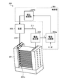
- FIG. 1 is a diagram showing a configuration of an electric discharge machining apparatus including an electrolysis apparatus according to Embodiment 1 of the present invention.
- FIG. 2 is a diagram showing the configuration of the control unit shown in FIG.
- the electric discharge machining apparatus 100 shown in FIG. The second pump 11, the filter 20, the upper wire guide 31 and the lower wire guide 32 that support the wire electrode 33, and the electrolyzer 200 are provided.
- the electric discharge machining apparatus 100 is a machine tool that performs electric discharge machining of the workpiece 30 by generating a pulse discharge in a gap between the wire electrode 33 that is a machining electrode and the workpiece 30 in the machining tank 1.
- the processing tank 1 is a tank in which electric discharge machining of the workpiece 30 is performed.
- the processing liquid 40 flows from the processing tank 1 into the dirty liquid tank 2 via the first pipe 4. Sludge is mixed in the processing liquid 40 flowing into the septic tank 2, and the processing liquid 40 in the septic tank 2 is pumped up by the first pump 10 and then sent to the filter 20 through the second pipe 5. It is done.
- the filter 20 is a filter that filters sludge contained in the machining liquid 40.
- the processing liquid 40 sent to the filter 20 is sent to the clean liquid tank 3 as a clear liquid from which sludge has been removed by being filtered by the filter 20.
- the processing liquid 40 filtered by the filter 20 flows into the clean liquid tank 3.
- the processing liquid 40 in the clean liquid tank 3 is supplied again to the processing tank 1 through the third pipe 6. In this way, the processing liquid 40 circulates in the processing tank 1, the dirty liquid tank 2, and the clean liquid tank 3.
- the upper wire guide 31 and the lower wire guide 32 are disposed together with the workpiece 30 in the processing tank 1 filled with the processing liquid 40.
- sludge that is an ionic impurity generated by electric discharge machining is ionized in the machining liquid 40 in the machining tank 1. Thereby, the electrical conductivity of the processing liquid 40 in the processing tank 1 increases.
- the electrolysis apparatus 200 is an apparatus that electrolyzes the machining liquid 40 in order to suppress an increase in the conductivity of the machining liquid 40.
- the electrolyzer 200 includes an electrode unit 201, a current detector 202, a power source 203, and a control unit 204.
- the electrode part 201 is installed in the processing tank 1 shown in FIG.
- the electrode unit 201 includes a plurality of electrodes 201a, and has a function of reducing the conductivity of the machining liquid 40 by precipitating metal ions in the machining liquid 40 on the surface of the electrode 201a.
- the gap between the adjacent electrodes 201a is set to, for example, about several mm in order to prevent clogging with sludge of about several ⁇ m. Thereby, it can suppress that the adjacent electrodes 201a are short-circuited by sludge.
- One end of the first wiring 210 and one end of the second wiring 211 are connected to the electrode unit 201.
- the other end of the first wiring 210 and the other end of the second wiring 211 are connected to the power source 203.
- the output voltage of the power source 203 is applied to the electrode unit 201 via the first wiring 210 and the second wiring 211.
- a current detector 202 is provided in the second wiring 211.
- the current detector 202 detects a current flowing through the second wiring 211.
- Current information indicating the value of the current detected by the current detector 202 is transmitted to the control unit 204.
- the current detector 202 may be a current sensor using an instrument current transformer called CT (Current Transformer), or may be a current sensor using a shunt resistor.
- CT Current Transformer
- the current detector 202 may be a combination of these.
- the current detector 202 may be provided in the first wiring 210 to detect a current flowing through this wiring.
- the control unit 204 illustrated in FIG. 2 includes a current comparison unit 204a and a voltage control unit 204b.
- the first current threshold value I1 and the second current threshold value I2 are set in the current comparison unit 204a.
- the current value I detected by the current detector 202 is compared with the first current threshold I1, and the current value I and the second current threshold I2 are compared.
- the comparison result is input to the voltage control unit 204b.
- the comparison result includes first information indicating that the current value I exceeds the first current threshold I1, second information indicating that the current value I is less than the second current threshold I2, and the like.
- the first current threshold value I1 is set to a value slightly lower than the current value detected by the current detector 202 when, for example, electric discharge machining cannot actually be performed. In other words, the first current threshold I1 has a high possibility that the conductivity of the machining fluid 40 increases due to the ionization of sludge in the machining fluid 40, and the machining fluid 40 does not function as an insulating medium. It is set to a value that can be determined. Specifically, the first current threshold I1 is 0.1 mA to 1.0 mA. Since the current value I detected by the current detector 202 varies depending on the specifications of the current detector 202 and the electrode unit 201, the first current threshold value I1 is such that the machining liquid 40 functions as an insulating medium. Any value can be used as long as it can be determined that there is a high possibility of disappearance, and the value is not limited to 0.1 mA to 1.0 mA.
- the second current threshold value I2 is set to a value higher than the first current threshold value I1.
- the second current threshold value I2 is a value about 100 times the first current threshold value I1, for example, 10.0 mA to 100 mA.
- the second current threshold value I2 is a current value determined by the value of the voltage V2, and a voltage V2 having a value capable of depositing metal ions in the machining liquid 40 on the surface of the electrode 201a of the electrode portion 201 is applied. As long as the current flows when it is applied, the current is not limited to 10.0 mA to 100 mA.
- the absolute value of the second current threshold value I2 is represented by a value about 1.2 to 1.4 times the first current threshold value I1.
- the voltage control unit 204b sets the power source 203 so that a voltage for depositing metal ions is applied to the electrode unit 201 when it is necessary to reduce the conductivity of the machining liquid 40. Control.
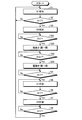
- FIG. 3 is a flowchart showing the operation of the control unit shown in FIG.
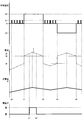
- FIG. 4 is a timing chart showing the operation of the control unit shown in FIG. FIG. 4 shows the voltage applied to the electrode unit 201 and the current detected by the current detector 202 in order from the top.
- the polarity of the voltage V2 is different from the polarity of the voltage V3, in FIG. 4, the current detected by the current detector 202 when the voltage V2 and the voltage V3 are applied is indicated by an absolute value.
- the current I is a positive value.
- the voltage control unit 204b controls the power source 203 so that the electric signal of the voltage V1 is applied to the electrode unit 201 at the timing of time t0 in FIG. 4 (step S1).
- the electric signal of voltage V1 is a signal applied to the electrode unit 201 in order to estimate the conductivity of the machining fluid 40. As shown in FIG. 4, this electric signal may be a periodically changing voltage that takes a binary potential of High level or Low level, or may be an electric signal that gives voltage V1 as a constant value. Hereinafter, the electric signal of voltage V1 is simply referred to as voltage V1.
- the current detector 202 detects the current value I.
- ⁇ A I / V1 (2) between the detected current value I, the applied voltage V1, and the conductivity of the machining fluid 40.
- ⁇ is the conductivity of the machining fluid 40.
- A is a constant determined by the surface area of the facing portion of the electrodes 201a facing each other and the distance between the facing electrodes 201a among the plurality of electrodes 201a provided in the electrode portion 201.
- the voltage control unit 204b estimates the conductivity of the machining liquid 40 by using the current value I flowing through the electrode unit 201 as information indicating the change in the conductivity of the machining liquid 40 without using a conductivity measuring sensor. can do.
- the machining liquid 40 is not electrolyzed when the voltage V1 is applied. Therefore, the electrical conductivity of the machining liquid 40 in the machining tank 1 increases with the electrical discharge machining.
- the current comparison unit 204a determines whether or not the detected current value I exceeds the first current threshold I1 (step S2), and when the current value I does not exceed the first current threshold I1 ( In step S2, No), the current comparison unit 204a repeats the processes in steps S1 and S2 until the current value I exceeds the first current threshold value I1.
- the current comparison unit 204a indicates that the current value I has exceeded the first current threshold value I1.
- the first information is notified to the voltage control unit 204b.
- the voltage control unit 204b to which the first information is input determines that there is a high possibility that the machining liquid 40 will not function as an insulating medium due to an increase in the conductivity of the machining liquid 40, and the voltage V2 is applied to the electrode unit 201.
- the power source 203 is controlled so as to be applied to (step S3).
- the voltage V2 is a first voltage applied to the electrode unit 201 in order to deposit metal ions in the machining liquid 40 on the surface of the electrode 201a of the electrode unit 201.
- the voltage V2 is higher than the voltage V1. Since it takes a certain time for the metal ions to deposit on the surface of the electrode 201a of the electrode part 201, as shown in FIG. 4, the conductivity in the machining liquid 40 decreases after a certain time has elapsed since the voltage V2 started to be applied. start.
- the control unit 204 performs an operation of switching the electrode 201a functioning as the cathode when the voltage V2 is applied to the anode. Details of this operation will be described later.
- the metal ions deposited on the electrode 201a as an oxide are a part of the metal ions in the working fluid 40, and therefore the increase in conductivity is affected even if the metal ions deposited on the electrode 201a are decomposed. There is nothing.
- the current comparison unit 204a determines whether or not the current value I is less than the first current threshold value I2 (step S4), and if the current value I is not less than the second current threshold value I2 (step S4). S4, No), the process of step S4 is repeated until the current value I becomes less than the second current threshold I2.
- the current comparison unit 204a indicates that the current value I is less than the second current threshold value I2. Is notified to the voltage control unit 204b.
- the voltage control unit 204b to which the second information is input determines that there is a low possibility that the machining liquid 40 does not function as an insulating medium due to a decrease in the conductivity of the machining liquid 40, and the voltage V1 is set to the electrode unit 201.
- the power source 203 is controlled so as to be applied to (step S5).
- the current comparison unit 204a determines whether or not the current value I exceeds the first current threshold value I1 (step S6), and if the current value I does not exceed the first current threshold value I1 (step S6). S6, No), the processes of steps S5 and S6 are repeated until the current value I exceeds the first current threshold value I1.
- the current comparison unit 204a indicates that the current value I exceeds the first current threshold value I1.
- the first information is notified to the voltage control unit 204b.
- the voltage control unit 204b to which the first information is input again controls the power supply 203 so that the voltage V3, which is the second voltage, is applied to the electrode unit 201 (step S7). ).
- the timing at which the voltage V3, which is the second voltage, is applied is when the current value I exceeds the first current threshold value I1 after the applied voltage has changed from the voltage V2 to the voltage V1.
- the voltage V3 has a polarity opposite to that of the voltage V2. This operation is for switching the electrode 201a functioning as the cathode when the voltage V2 is applied to the anode.
- the voltage V3 may have an absolute value equal to the absolute value of the voltage V2 and a polarity opposite to the polarity of the voltage V2, depending on the specifications of the electrode unit 201, the upper limit of the conductivity of the machining liquid 40, and the like. Is set.
- the timing for starting the application of the voltage V3 may be, for example, after a predetermined time has elapsed from the time when the voltage V2 is changed to the voltage V1, or even when the total application time of the voltage V2 exceeds a preset value. Good.
- the voltage control unit 204b determines whether or not the current value I is less than the second current threshold value I2 (step S8), and when the current value I is not less than the second current threshold value I2 (step S8). (S8, No), the current comparison unit 204a repeats the process of step S8 until the current value I becomes less than the second current threshold I2.
- step S8 When the current value I becomes less than the second current threshold value I2 at the timing of time t4 (step S8, Yes), the current comparison unit 204a indicates that the current value I becomes less than the second current threshold value I2. Is notified to the voltage control unit 204b.
- the voltage control unit 204b to which the second information is input executes the process of step S1.
- the electric discharge machining apparatus 100 including the electrolysis apparatus 200 reduces the conductivity of the machining liquid 40 based on the current value I that is information indicating the change in the conductivity of the machining liquid 40.
- a first voltage for depositing metal ions is applied to the electrode unit 201. Therefore, in the electric discharge machining apparatus 100, since the ion exchange function of the ion exchange resin does not decrease, the conductivity of the machining liquid 40 can be decreased without using the ion exchange resin. Therefore, compared with the case where ion exchange resin is used, the maintainability of the electric discharge machining apparatus 100 is improved, and an increase in running cost of the electric discharge machining apparatus 100 can be suppressed.
- FIG. FIG. 5 is a diagram showing a configuration of an electric discharge machining apparatus including an electrolysis apparatus according to Embodiment 2 of the present invention.
- the electric discharge machining apparatus 100A according to Embodiment 2 includes an electrolysis apparatus 200A instead of the electrolysis apparatus 200.
- the electric discharge machining apparatus 100 ⁇ / b> A includes an upper wire guide 31, a lower wire guide 32, a first pump 10, a second pump 11, a filter 20, and a third pump 12 that pumps up the machining liquid 40.
- the electrolyzer 200A includes a control unit 204A instead of the control unit 204.
- the electrolyzer 200 ⁇ / b> A includes an electromagnetic valve 22 and an ion exchange resin 23 in addition to the electrode unit 201, the current detector 202, and the power source 203.
- the solenoid valve 22 has a function of passing the machining liquid 40 pumped up by the third pump 12 to the ion exchange resin 23 or blocking the machining liquid 40 pumped up by the third pump 12 from passing through the ion exchange resin 23.
- the ion exchange resin 23 has a function of controlling the conductivity of the machining liquid 40 by performing ion exchange of the machining liquid 40.
- FIG. 6 is a diagram showing the configuration of the control unit shown in FIG.
- the control unit 204A includes a current comparison unit 204c and a voltage control unit 204d instead of the current comparison unit 204a and the voltage control unit 204b of the first embodiment.
- a first current threshold value I1 and a second current threshold value I2 are set, and a third current threshold value I3 is set.
- the third current threshold value I3 is set to a value higher than the second current threshold value I2.
- the third current threshold value I3 is that the conductivity of the machining fluid 40 increases due to ionization of sludge in the machining fluid 40, and the conductivity of the machining fluid 40 increases only by applying the voltage V2 to the electrode portion 201. Is set to a value at which it can be determined that there is a high possibility of being unable to be suppressed.
- the current comparison unit 204c the current value I detected by the current detector 202 is compared with the first current threshold value I1, and the current value I and the second current threshold value I2 are compared. Further, the current comparison unit 204c compares the current value I with the third current threshold I3. The comparison result is input to the voltage control unit 204d.
- the voltage control unit 204d Based on the comparison result from the current comparison unit 204c, the voltage control unit 204d turns on the power source 203 so that a voltage for depositing metal ions is applied to the electrode unit 201 when it is necessary to reduce the conductivity of the machining liquid 40. Control. Furthermore, the voltage control unit 204d opens the solenoid valve 22 when the machining liquid 40 pumped up by the third pump 12 needs to pass through the ion exchange resin 23 based on the comparison result from the current comparison unit 204c. Control.
- FIG. 7 is a flowchart showing the operation of the control unit shown in FIG.
- FIG. 8 is a timing chart showing the operation of the control unit shown in FIG. FIG. 8 shows, in order from the top, the voltage applied to the electrode unit 201, the current detected by the current detector 202, and the state of the electromagnetic valve.
- step S1 to step S3 and the processing operations from step S4 to step S8 are the same as those in the first embodiment, and therefore only the processing operations different from those in the first embodiment will be described below. .
- the current comparison unit 204c determines whether or not the current value I exceeds the third current threshold I3 (step S31), and the current value I is the third current threshold. When the value I3 is not exceeded (No at Step S31), the process at Step S31 is repeated until the current value I exceeds the third current threshold I3.
- the current comparison unit 204c determines that the current value I exceeds the third current threshold value I3.
- the third information shown is notified to the voltage control unit 204d.
- the voltage control unit 204d to which the third information is input determines that there is a high possibility that the increase in the conductivity of the machining fluid 40 cannot be suppressed only by applying the voltage V2 to the electrode unit 201.
- the electromagnetic valve 22 is controlled to change to the open state (step S32).
- the voltage control unit 204d supplies power so that the voltage V2 is applied to the electrode unit 201 when it is necessary to lower the conductivity of the machining liquid 40 and to pass the machining liquid 40 through the ion exchange resin 23. While controlling 203, the electromagnetic valve 22 is controlled so that the machining liquid 40 passes through the ion exchange resin 23.
- the current comparison unit 204c determines whether or not the current value I has become equal to or lower than the third current threshold I3 due to the electromagnetic valve 22 being changed to the open state (step S33), and the current value I is the third current. If it is not less than or equal to the threshold value I3 (step S33, No), the process of step S33 is repeated until the current value I becomes equal to or less than the third current threshold value I3.
- the current comparison unit 204c causes the current value I to become equal to or lower than the third current threshold value I3.
- the fourth information indicating this is notified to the voltage control unit 204d.
- the voltage control unit 204d to which the fourth information is input determines that the increase in the conductivity of the machining fluid 40 can be suppressed only by applying the voltage V2 to the electrode unit 201, and the electromagnetic valve 22 changes from the open state to the closed state.
- the electromagnetic valve 22 is controlled so as to be performed (step S34).
- the voltage control unit 204d supplies power so that the voltage V2 is applied to the electrode unit 201 when it is necessary to reduce the conductivity of the processing liquid 40 and it is not necessary to pass the processing liquid 40 through the ion exchange resin 23.
- the electromagnetic valve 22 is controlled so as to stop the passage of the machining fluid 40 to the ion exchange resin 23.
- the machining liquid 40 that has passed through the ion exchange resin 23 is supplied to the clean liquid tank 3, but the electric discharge machining apparatus 100A has a machining that has passed through the ion exchange resin 23. You may comprise so that the liquid 40 may be supplied to the processing tank 1 or the waste liquid tank 2.
- FIG. 1 the electric discharge machining apparatus 100A according to Embodiment 2
- the third pump 12 is provided in the clean liquid tank 3.
- the electric discharge machining apparatus 100A replaces the third pump 12 with the machining tank 1 or the dirty liquid tank 2. You may comprise so that it may provide.
- the electromagnetic valve 22 is used in the electric discharge machining apparatus 100A according to the second embodiment.
- the electric discharge machining apparatus 100A is an air-operated opening / closing that opens and closes by supplying or stopping air pressure instead of the electromagnetic valve 22. You may comprise so that a valve may be provided.
- the electric discharge machining apparatus 100A for example, even when the machining amount of the workpiece 30 is increased and the conductivity of the machining liquid 40 is rapidly increased, the electrolysis of the electrode unit 201 is performed. Since the ion exchange of the ion exchange resin 23 is assisted, an increase in the conductivity of the processing liquid 40 is suppressed.
- the ion exchange resin 23 is used so as to assist the electrolysis by the electrode part 201, only the ion exchange resin 23 is used without using the electrode part 201. Compared to the case where the ion exchange resin 23 is clogged, clogging of the ion exchange resin 23 is suppressed, and the exchange cycle of the ion exchange resin 23 can be extended.
- the electrode unit 201 is provided in the machining tank 1.
- the electrode unit 201 is the septic tank 2 or the cleaning tank. You may comprise so that it may be provided in the liquid tank 3. FIG.
- the electrode unit 201 is provided in the dirty liquid tank 2 or the clean liquid tank 3, an increase in conductivity in the processing liquid 40 can be suppressed.
- the electrical conductivity of the processing liquid 40 in the processing tank 1 is higher than the electrical conductivity of the processing liquid 40 in the dirty liquid tank 2 or the clean liquid tank 3.
- the processing liquid 40 from the processing tank 1 is supplied to the dirty liquid tank 2 through the first pipe 4, the change in the conductivity of the processing liquid 40 in the dirty liquid tank 2 is changed in the processing tank 1. There is a tendency to lag behind the change in the conductivity of the machining fluid 40.
- the conductivity of the processing liquid 40 existing around the workpiece 30 compared to the case where the electrode part 201 is provided in the dirty liquid tank 2 or the clean liquid tank 3.
- the change in rate can be detected accurately, and the conductivity of the machining fluid 40 existing around the workpiece 30 can be quickly reduced. Therefore, the function of the machining liquid 40 as an insulating medium can be sufficiently exhibited.
- the number of electrode portions 201 used in the electric discharge machining apparatuses 100 and 100A according to the first and second embodiments is not limited to one, and may be two or more.
- the electrolysis apparatuses 200 and 200A according to the first and second embodiments can be used for electrolysis of the machining fluid 40 used for machine tools other than the electric discharge machining apparatuses 100 and 100A.
- the machine tool includes, for example, a machining apparatus that performs electrical discharge machining using the machining liquid 40 that is discharged from the nozzles of the upper wire guide 31 and the lower wire guide 32 without immersing the workpiece 30 in the machining liquid 40, and the machining liquid 40. Machining center that performs machining using
- the current detector 202 is used as a conductivity measuring unit.
- the electrolysis apparatuses 200 and 200A are replaced with the current detector 202.
- a conductivity measuring sensor may be provided.
- the conductivity measuring sensor includes, for example, two electrodes in contact with the machining fluid 40, measures the resistance value between the two electrodes, and calculates the reciprocal of the resistance value per unit area of the two electrodes as the conductivity. .
- the calculated conductivity is information indicating a change in the conductivity of the machining liquid 40.
- control unit 204A When using the conductivity measuring sensor, the control unit 204A includes a conductivity comparing unit instead of the current comparing unit 204c. The conductivity from the conductivity measurement sensor is input to the conductivity comparison unit.
- a first conductivity threshold value ⁇ 1, a second conductivity threshold value ⁇ 2, and a third conductivity threshold value ⁇ 3 are set.
- the first conductivity threshold value ⁇ 1 is set to a value slightly lower than the conductivity value measured when, for example, electrical discharge machining cannot actually be performed. That is, the first conductivity threshold value ⁇ 1 is highly likely that the conductivity of the machining fluid 40 increases due to the ionization of sludge in the machining fluid 40, and the machining fluid 40 does not function as an insulating medium. It is set to a value that can be determined.
- the second conductivity threshold value ⁇ 2 is set higher than the first conductivity threshold value ⁇ 1.
- the third conductivity threshold value ⁇ 3 is set to a value higher than the second conductivity threshold value ⁇ 2.
- the third conductivity threshold value ⁇ 3 is that the conductivity of the machining fluid 40 increases due to ionization of sludge in the machining fluid 40, and the conductivity of the machining fluid 40 can be increased only by applying the voltage V2 to the electrode portion 201. It is set to a value at which it can be determined that there is a high possibility that the increase cannot be suppressed.
- the control unit including the conductivity comparison unit in which a plurality of conductivity threshold values are set the conductivity measured by the conductivity measurement sensor and the conductivity are similar to the case of including the current comparison unit 204c.
- the threshold value is compared, and voltage control applied to the electrode unit 201 or opening / closing control of the electromagnetic valve 22 is performed according to the comparison result.
- FIG. 9 is a diagram showing the relationship between the current value and the conductivity shown in FIG.
- the horizontal axis in FIG. 9 indicates the current value, and the vertical axis indicates the amount of decrease in conductivity per hour. As the current value increases, the conductivity decreases, and a sufficient electrolysis effect can be expected if the upper limit of the current value is set to 1A.
- the configuration described in the above embodiment shows an example of the contents of the present invention, and can be combined with another known technique, and can be combined with other configurations without departing from the gist of the present invention. It is also possible to omit or change the part.
- 1 Processing tank 2 Soil tank, 3 Liquid tank, 4 1st piping, 5 2nd piping, 6 3rd piping, 10 1st pump, 11 2nd pump, 12 3rd pump, 20 filter, 22 Solenoid valve , 23 ion exchange resin, 30 workpiece, 31 upper wire guide, 32 lower wire guide, 33 wire electrode, 40 machining fluid, 100, 100A electric discharge machine, 200, 200A electrolyzer, 201 electrode part, 201a electrode, 202 current detector, 203 power supply, 204, 204A control unit, 204a, 204c current comparison unit, 204b, 204d voltage control unit, 210 first wiring, 211 second wiring, 400 processor, 401 memory.
Landscapes
- Chemical & Material Sciences (AREA)
- Engineering & Computer Science (AREA)
- Chemical Kinetics & Catalysis (AREA)
- Electrochemistry (AREA)
- Materials Engineering (AREA)
- Metallurgy (AREA)
- Organic Chemistry (AREA)
- Mechanical Engineering (AREA)
- Electrical Discharge Machining, Electrochemical Machining, And Combined Machining (AREA)
- Electrolytic Production Of Metals (AREA)
Abstract
電気分解装置(200)は、複数の電極(201a)を備え、加工液の金属イオンを電極(201a)に析出させる電極部(201)と、電極部(201)に電圧を印加する電源(203)とを備える。電気分解装置(200)は、加工液の導電率を低下させる必要があるとき、電極部(201)に金属イオンを析出させる第1電圧が電極部(201)へ印加されるように電源(203)を制御し、第1電圧が電極部(201)へ印加された後、加工液の導電率を低下させる必要があるとき、第1電圧の極性とは逆極性の第2電圧が電極部(201)へ印加されるように電源(203)を制御する制御部(204)を備える。
Description
本発明は、被加工物の放電加工に利用する加工液を電気分解する電気分解装置及び電気分解装置を備えた放電加工装置に関する。
従来より、被加工物を加工槽内の加工液中に浸して加工する放電加工装置が知られている。この種の放電加工装置では、ワイヤ電極と被加工物との間の隙間にパルス放電を生じさせて被加工物の放電加工が行われる。放電加工によって発生したスラッジが加工液中でイオン化することにより加工液の導電率が上昇すると、加工液が絶縁媒体としての機能を果たさなくなり、放電加工を行うことができなくなる。従って、放電加工においては、加工液の導電率の上昇を抑制する必要がある。
特許文献1には、加工液の導電率が基準値を超えたときに加工液をイオン交換樹脂に通過させることにより、加工液の導電率の上昇を抑制する技術が開示されている。
しかしながら特許文献1に開示される技術では、イオン交換が一定量行われるとイオン交換樹脂のイオン交換機能が低下して、導電率の上昇を抑制することができなくなるため、定期的にイオン交換樹脂を交換する必要がある。このようにイオン交換樹脂は消耗品であるため、特許文献1に開示される技術では、定期的にイオン交換樹脂を交換する必要があるという課題があった。
本発明は、上記に鑑みてなされたものであって、定期的な交換を要する消耗品を用いることなく加工液の導電率の上昇を抑制できる電気分解装置を得ることを目的とする。
上述した課題を解決し、目的を達成するために、本発明の電気分解装置は、複数の電極を備え、加工液の金属イオンを電極に析出させる電極部と、電極部に電圧を印加する電源とを備える。電気分解装置は、加工液の導電率を低下させる必要があるとき、電極部に金属イオンを析出させる第1電圧が電極部へ印加されるように電源を制御し、第1電圧が電極部へ印加された後、加工液の導電率を低下させる必要があるとき、第1電圧の極性とは逆極性の第2電圧が電極部へ印加されるように電源を制御する制御部を備えることを特徴とする。
本発明に係る電気分解装置は、定期的な交換を要する消耗品を用いることなく加工液の導電率の上昇を抑制できるという効果を奏する。
以下に、本発明の実施の形態に係る電気分解装置及び放電加工装置を図面に基づいて詳細に説明する。なお、この実施の形態によりこの発明が限定されるものではない。
実施の形態1.
図1は本発明の実施の形態1に係る電気分解装置を備える放電加工装置の構成を示す図である。図2は図1に示す制御部の構成を示す図である。図1に示す放電加工装置100は、加工槽1と、汚液槽2と、清液槽3と、第1配管4と、第2配管5と、第3配管6と、第1ポンプ10と、第2ポンプ11と、フィルタ20と、ワイヤ電極33を支持する上部ワイヤガイド31及び下部ワイヤガイド32と、電気分解装置200とを備える。
図1は本発明の実施の形態1に係る電気分解装置を備える放電加工装置の構成を示す図である。図2は図1に示す制御部の構成を示す図である。図1に示す放電加工装置100は、加工槽1と、汚液槽2と、清液槽3と、第1配管4と、第2配管5と、第3配管6と、第1ポンプ10と、第2ポンプ11と、フィルタ20と、ワイヤ電極33を支持する上部ワイヤガイド31及び下部ワイヤガイド32と、電気分解装置200とを備える。
放電加工装置100は、加工槽1において、加工電極であるワイヤ電極33と被加工物30との間の隙間にパルス放電を生じさせて被加工物30の放電加工を行う工作機械である。
加工槽1は、被加工物30の放電加工が行なわれる槽である。汚液槽2には、第1配管4を介して、加工槽1から加工液40が流入する。汚液槽2に流入する加工液40にはスラッジが混ざっており、汚液槽2内の加工液40は、第1ポンプ10でくみ上げられた後、第2配管5を介してフィルタ20へ送られる。
フィルタ20は、加工液40に含まれるスラッジを濾過する濾過器である。フィルタ20に送られた加工液40は、フィルタ20で濾過されることによって、スラッジが除去された清液として清液槽3へ送られる。
清液槽3には、フィルタ20で濾過された加工液40が流入する。清液槽3内の加工液40は、第3配管6を介して再び加工槽1へ供給される。このようにして、加工液40は、加工槽1、汚液槽2及び清液槽3を循環する。
加工液40で満たされている加工槽1内には、上部ワイヤガイド31及び下部ワイヤガイド32が被加工物30と共に配置される。ワイヤ電極33による被加工物30への放電加工が行われると、放電加工によって生じたイオン性不純物であるスラッジが、加工槽1内の加工液40中でイオン化する。これにより加工槽1内の加工液40の導電率が上昇する。
加工液40の導電率が上昇すると、加工液40が絶縁媒体としての機能を果たさなくなり、放電加工を行うことができなくなる。電気分解装置200は、加工液40の導電率の上昇を抑制するために加工液40を電気分解する装置である。
電気分解装置200は、電極部201、電流検出器202、電源203及び制御部204を備える。
電極部201は、図1に示す加工槽1内に設置される。電極部201は、複数の電極201aを備え、加工液40中の金属イオンを電極201aの表面に析出させることで、加工液40の導電率を低下させる機能を有する。なお、隣接する電極201a同士の間の隙間は、数μm程度のスラッジが目詰まりしないようにするため、例えば数mm程度に設定される。これにより、隣接する電極201a同士がスラッジによって短絡することを抑制できる。
電極部201には、第1配線210の一端と第2配線211の一端とが接続される。第1配線210の他端と第2配線211の他端とは電源203に接続される。電源203の出力電圧は、第1配線210及び第2配線211を介して電極部201に印加される。
第2配線211には電流検出器202が設けられている。電流検出器202は、第2配線211に流れる電流を検出する。電流検出器202で検出された電流の値を示す電流情報は制御部204へ伝送される。
電流検出器202は、CT(Current Transformer)と呼ばれる計器用変流器を用いた電流センサであってもよいし、シャント抵抗を用いた電流センサであってもよい。また電流検出器202は、これらを組み合わせたものでもよい。なお電流検出器202は、第1配線210に設けて、この配線に流れる電流を検出してもよい。
次に制御部204の構成を説明する。図2に示す制御部204は、電流比較部204a及び電圧制御部204bを備える。
電流比較部204aには、第1電流しきい値I1と第2電流しきい値I2とが設定されている。電流比較部204aでは、電流検出器202で検出された電流値Iと第1電流しきい値I1とが比較され、また電流値Iと第2電流しきい値I2とが比較される。比較結果は、電圧制御部204bに入力される。比較結果は、電流値Iが第1電流しきい値I1を超えたことを示す第1情報、電流値Iが第2電流しきい値I2未満となったことを示す第2情報などである。
第1電流しきい値I1は、例えば実際に放電加工ができなくなったときに電流検出器202で検出された電流の値よりも僅かに低い値に設定される。すなわち、第1電流しきい値I1は、スラッジが加工液40中でイオン化することによって加工液40の導電率が上昇して、加工液40が絶縁媒体としての機能を果たさなくなる可能性が高いと判断できる値に設定される。具体的には第1電流しきい値I1は0.1mA~1.0mAである。なお、電流検出器202で検出される電流値Iは電流検出器202及び電極部201の仕様によっても変動するため、第1電流しきい値I1は、加工液40が絶縁媒体としての機能を果たさなくなる可能性が高いと判断できる値であればよく、0.1mA~1.0mAに限定されるものではない。
第2電流しきい値I2は、第1電流しきい値I1よりも高い値に設定される。第2電流しきい値I2は、I2=I1×V2/V1・・・(1)の関係を満たす値で表すことができる。具体的には、第2電流しきい値I2は、第1電流しきい値I1の100倍程度の値であり、例えば10.0mA~100mAである。第2電流しきい値I2は、電圧V2の値により決まる電流値であり、加工液40中の金属イオンを電極部201の電極201aの表面に析出させることができるような値の電圧V2が印加されたときに流れる電流あれば、10.0mA~100mAに限定されるものではない。なお図4では、説明の便宜上、第2電流しきい値I2の絶対値が第1電流しきい値I1の1.2~1.4倍程度の値で表記されている。
電圧制御部204bは、電流比較部204aからの比較結果に基づき、加工液40の導電率を低下させる必要があるとき、金属イオンを析出させる電圧が電極部201へ印加されるように電源203を制御する。
次に図3及び図4を用いて制御部204の動作について説明する。図3は図2に示す制御部の動作を示すフローチャートである。図4は図3に示す制御部の動作を示すタイミングチャートである。図4には上から順に、電極部201に印加される電圧と、電流検出器202で検出される電流とが示される。なお、電圧V2の極性は電圧V3の極性と異なるが、図4では、これらの電圧V2及び電圧V3が印加されたときに電流検出器202で検出される電流が絶対値で示されているため、電流Iの値が正の値となっている。
電圧制御部204bは、図4の時刻t0のタイミングで電圧V1の電気信号が電極部201へ印加されるように電源203を制御する(ステップS1)。
電圧V1の電気信号は、加工液40の導電率を推定するために電極部201に印加される信号である。この電気信号は、図4に示すようにHighレベル、又はLowレベルの2値の電位を取る周期的に変化する電圧でもよいし、一定値として電圧V1を与える電気信号でもよい。以下では電圧V1の電気信号を単に電圧V1と称する。
電圧V1が印加されることにより、電流検出器202では電流値Iが検出される。検出される電流値Iと、印加される電圧V1と、加工液40の導電率との間には、σA=I/V1・・・(2)の関係がある。σは加工液40の導電率である。Aは、電極部201が備える複数の電極201aの内、互いに対向する電極201aの対向部分の表面の面積と、対向する電極201a間の距離とによって定まる定数である。
上記(2)式より、σが増加するとIは増加し、σが減少するとIが減少することが分かる。このように電流値Iは、加工液40の導電率と相関がある。なお、電圧V2が印加されているときには、電流値Iと電圧V2と導電率との間には、σA=I/V2・・・(3)の関係があるため、(3)式を利用することにより、電圧V2が印加されているときの加工液40の導電率の推定が可能である。また、電圧V3が印加されているときには、電流値Iと電圧V3と導電率との間には、σA=I/V3・・・(4)の関係があるため、(4)式を利用することにより、電圧V3が印加されているときの加工液40の導電率の推定が可能である。
電圧制御部204bは、導電率測定センサを用いることなく、電極部201に流れる電流値Iを、加工液40の導電率の変化を示す情報として利用することによって、加工液40の導電率を推定することができる。
なお、電圧V1の印加は加工液40の導電率を推定することを目的として行われるため、電圧V1が印加されているときには加工液40の電気分解は行われない。従って、加工槽1内の加工液40の導電率は、放電加工が継続されると、それに伴って上昇する。
電流比較部204aは、検出される電流値Iが第1電流しきい値I1を超えたか否かを判断し(ステップS2)、電流値Iが第1電流しきい値I1を超えていない場合(ステップS2,No)、電流比較部204aは、電流値Iが第1電流しきい値I1を超えるまでステップS1,S2の処理を繰り返す。
時刻t1のタイミングで電流値Iが第1電流しきい値I1を超えた場合(ステップS2,Yes)、電流比較部204aは、電流値Iが第1電流しきい値I1を超えたことを示す第1情報を電圧制御部204bへ通知する。
第1情報が入力された電圧制御部204bは、加工液40の導電率が上昇することによって加工液40が絶縁媒体としての機能を果たさなくなる可能性が高いと判断し、電圧V2が電極部201へ印加されるように電源203を制御する(ステップS3)。
電圧V2は、加工液40中の金属イオンを電極部201の電極201aの表面に析出させるために、電極部201へ印加される第1電圧である。電圧V2は電圧V1よりも高い電圧である。金属イオンが電極部201の電極201aの表面に析出するまでには一定時間要するため、図4に示すように、電圧V2が印加され始めてから一定時間経過後に加工液40中の導電率が低下し始める。
なお、電極部201の電極201aの表面に析出した金属イオンは、その一部が酸化物として、陰極として機能する電極201aの表面に残留する。この酸化物は、電極201aの電気的物性を変化させてしまうため、電気分解性能が低下する原因になり、また導電率測定精度が低下する原因になる。制御部204は、この酸化物を分解するため、電圧V2の印加時に陰極として機能していた電極201aを、陽極に切り替える動作を行う。この動作の詳細は後述する。なお、酸化物として電極201aに析出する金属イオンは、加工液40中の金属イオンの一部であるため、電極201aに析出する金属イオンが分解されても、導電率の上昇には影響を与えることがない。
電流比較部204aは、電流値Iが第1電流しきい値I2未満となったか否かを判断し(ステップS4)、電流値Iが第2電流しきい値I2未満となっていない場合(ステップS4,No)、電流値Iが第2電流しきい値I2未満となるまでステップS4の処理を繰り返す。
時刻t2のタイミングで電流値Iが第2電流しきい値I2未満となった場合(ステップS4,Yes)、電流比較部204aは、電流値Iが第2電流しきい値I2未満となったことを示す第2情報を電圧制御部204bへ通知する。
第2情報が入力された電圧制御部204bは、加工液40の導電率が低下することによって加工液40が絶縁媒体としての機能を果たさなくなる可能性が低いと判断し、電圧V1が電極部201へ印加されるように電源203を制御する(ステップS5)。
その後、電流比較部204aは、電流値Iが第1電流しきい値I1を超えたか否かを判断し(ステップS6)、電流値Iが第1電流しきい値I1を超えていない場合(ステップS6,No)、電流値Iが第1電流しきい値I1を超えるまでステップS5,S6の処理を繰り返す。
時刻t3のタイミングで電流値Iが第1電流しきい値I1を超えた場合(ステップS6,Yes)、電流比較部204aは、電流値Iが第1電流しきい値I1を超えたことを示す第1情報を電圧制御部204bへ通知する。
電圧V2から電圧V1へ変化した後、再び第1情報が入力された電圧制御部204bは、第2電圧である電圧V3が電極部201へ印加されるように、電源203を制御する(ステップS7)。第2電圧である電圧V3が印加されるタイミングは、印加電圧が電圧V2から電圧V1へ変化した後に、電流値Iが第1電流しきい値I1を超えたときである。
電圧V3は電圧V2の極性とは逆極性の電圧である。この動作は、電圧V2の印加時に陰極として機能していた電極201aを陽極に切り替えるためのものである。
なお、電圧V3は、その絶対値が電圧V2の絶対値に等しく、かつ、極性が電圧V2の極性と逆であればよく、電極部201の仕様、加工液40の導電率の上限などに応じて設定される。また、電圧V3の印加を開始するタイミングは、例えば電圧V2から電圧V1へ変化した時点から一定時間経過後でもよいし、電圧V2の印加時間合計値が予め設定された設定値を超えたときでもよい。
図4に示すように、電圧V3の印加時に陰極として機能する電極201aに金属イオンが析出することにより加工液40の導電率が低下する。
電圧制御部204bは、電流値Iが第2電流しきい値I2未満となったか否かを判断し(ステップS8)、電流値Iが第2電流しきい値I2未満となっていない場合(ステップS8,No)、電流比較部204aは、電流値Iが第2電流しきい値I2未満となるまでステップS8の処理を繰り返す。
時刻t4のタイミングで電流値Iが第2電流しきい値I2未満となった場合(ステップS8,Yes)、電流比較部204aは、電流値Iが第2電流しきい値I2未満となったことを示す第2情報を電圧制御部204bへ通知する。第2情報が入力された電圧制御部204bは、ステップS1の処理を実行する。
従来のイオン交換樹脂を用いた場合、イオン交換が一定量行われるとイオン交換樹脂のイオン交換機能が低下し、導電率の上昇を抑制することができなくなる。そのため、定期的にイオン交換樹脂を交換する必要がある。
これに対して実施の形態1に係る電気分解装置200を備えた放電加工装置100は、加工液40の導電率の変化を示す情報である電流値Iに基づいて加工液40の導電率を低下させる必要があると判断したとき、金属イオンを析出させる第1電圧を、電極部201へ印加する。そのため、放電加工装置100では、イオン交換樹脂のイオン交換機能が低下することがないため、イオン交換樹脂を用いることなく、加工液40の導電率を低下させることができる。従って、イオン交換樹脂を用いる場合に比べて、放電加工装置100のメンテナンス性が向上し、また放電加工装置100のランニングコストの増加を抑制できる。
実施の形態2.
図5は本発明の実施の形態2に係る電気分解装置を備える放電加工装置の構成を示す図である。実施の形態2に係る放電加工装置100Aは、電気分解装置200に代えて電気分解装置200Aを備える。
図5は本発明の実施の形態2に係る電気分解装置を備える放電加工装置の構成を示す図である。実施の形態2に係る放電加工装置100Aは、電気分解装置200に代えて電気分解装置200Aを備える。
また放電加工装置100Aは、上部ワイヤガイド31と、下部ワイヤガイド32と、第1ポンプ10と、第2ポンプ11と、フィルタ20と、加工液40をくみ上げる第3ポンプ12とを備える。
電気分解装置200Aは、制御部204に代えて制御部204Aを備える。また電気分解装置200Aは、電極部201、電流検出器202及び電源203に加えて、電磁弁22及びイオン交換樹脂23を備える。
電磁弁22は、第3ポンプ12でくみ上げられた加工液40をイオン交換樹脂23へ通過させ、又は第3ポンプ12でくみ上げられた加工液40のイオン交換樹脂23への通過を遮断する機能を有する。イオン交換樹脂23は、加工液40のイオン交換を行うことにより加工液40の導電率を制御する機能を有する。
次に図5に示す制御部204Aの構成を説明する。図6は図5に示す制御部の構成を示す図である。
制御部204Aは、実施の形態1の電流比較部204a及び電圧制御部204bに代えて、電流比較部204c及び電圧制御部204dを備える。
電流比較部204cには、第1電流しきい値I1及び第2電流しきい値I2が設定されると共に、第3電流しきい値I3が設定される。
第3電流しきい値I3は、第2電流しきい値I2よりも高い値に設定される。第3電流しきい値I3は、スラッジが加工液40中でイオン化することによって加工液40の導電率が上昇して、電極部201への電圧V2の印加だけでは加工液40の導電率の上昇を抑制できない可能性が高いと判断できる値に設定される。
電流比較部204cでは、電流検出器202で検出された電流値Iと第1電流しきい値I1とが比較され、また電流値Iと第2電流しきい値I2とが比較される。さらに、電流比較部204cでは、電流値Iと第3電流しきい値I3とが比較される。比較結果は、電圧制御部204dに入力される。
電圧制御部204dは、電流比較部204cからの比較結果に基づき、加工液40の導電率を低下させる必要があるとき、金属イオンを析出させる電圧が電極部201へ印加されるように電源203を制御する。さらに電圧制御部204dは、電流比較部204cからの比較結果に基づき、第3ポンプ12でくみ上げられた加工液40をイオン交換樹脂23に通過させる必要があるとき、電磁弁22を開放するように制御する。
次に図7及び図8を用いて制御部204Aの動作について説明する。図7は図6に示す制御部の動作を示すフローチャートである。図8は図7に示す制御部の動作を示すタイミングチャートである。図8には上から順に、電極部201に印加される電圧と、電流検出器202で検出される電流と、電磁弁の状態とが示される。
電気分解装置200Aの動作が開始されるときには、電磁弁22が閉じており、イオン交換樹脂23へ加工液40が通過していないものとする。また図7において、ステップS1からステップS3までの処理動作と、ステップS4からステップS8までの処理動作とは実施の形態1と同様であるため、以下では実施の形態1と異なる処理動作のみ説明する。
ステップS3で電圧V2が印加された後、電流比較部204cは、電流値Iが第3電流しきい値I3を超えたか否かを判断し(ステップS31)、電流値Iが第3電流しきい値I3を超えていない場合(ステップS31,No)、電流値Iが第3電流しきい値I3を超えるまでステップS31の処理を繰り返す。
時刻t1’のタイミングで電流値Iが第3電流しきい値I3を超えた場合(ステップS31,Yes)、電流比較部204cは、電流値Iが第3電流しきい値I3を超えたことを示す第3情報を電圧制御部204dへ通知する。
第3情報が入力された電圧制御部204dは、電極部201への電圧V2の印加だけでは加工液40の導電率の上昇を抑制できない可能性が高いと判断し、電磁弁22が閉塞状態から開放状態に変化するように電磁弁22を制御する(ステップS32)。
すなわち、電圧制御部204dは、加工液40の導電率を低下させる必要がありかつイオン交換樹脂23に加工液40を通過させる必要があるとき、電圧V2が電極部201へ印加されるように電源203を制御しながら、加工液40をイオン交換樹脂23へ通過させるように電磁弁22を制御する。
これにより、電極部201の電気分解に、イオン交換樹脂23のイオン交換がアシストされるため、加工液40の導電率の上昇が抑制される。
電流比較部204cは、電磁弁22が開放状態に変化したことによって電流値Iが第3電流しきい値I3以下になったか否かを判断し(ステップS33)、電流値Iが第3電流しきい値I3以下になっていない場合(ステップS33,No)、電流値Iが第3電流しきい値I3以下になるまでステップS33の処理を繰り返す。
時刻t1’’のタイミングで電流値Iが第3電流しきい値I3以下になった場合(ステップS33,Yes)、電流比較部204cは、電流値Iが第3電流しきい値I3以下になったことを示す第4情報を電圧制御部204dへ通知する。
第4情報が入力された電圧制御部204dは、電極部201への電圧V2の印加だけで加工液40の導電率の上昇を抑制できると判断し、電磁弁22が開放状態から閉塞状態に変化するように電磁弁22を制御する(ステップS34)。
すなわち、電圧制御部204dは、加工液40の導電率を低下させる必要がありかつイオン交換樹脂23に加工液40を通過させる必要がないとき、電圧V2が電極部201へ印加されるように電源203を制御しながら、加工液40のイオン交換樹脂23への通過を停止させるように電磁弁22を制御する。
なお、実施の形態2に係る放電加工装置100Aでは、イオン交換樹脂23を通過した加工液40が清液槽3に供給されているが、放電加工装置100Aは、イオン交換樹脂23を通過した加工液40が加工槽1又は汚液槽2に供給されるように構成してもよい。
また、実施の形態2に係る放電加工装置100Aでは、第3ポンプ12が清液槽3に設けられているが、放電加工装置100Aは、第3ポンプ12を加工槽1又は汚液槽2に設けるように構成してもよい。
また、実施の形態2に係る放電加工装置100Aでは、電磁弁22が用いられているが、放電加工装置100Aは、電磁弁22の代わりに、空気圧の供給又は停止により開閉する空気作動方式の開閉弁を備えるように構成してもよい。
以上に説明したように実施の形態2に係る放電加工装置100Aでは、例えば被加工物30の加工量が多くなり加工液40の導電率が急激に上昇した場合でも、電極部201の電気分解に、イオン交換樹脂23のイオン交換がアシストされるため、加工液40の導電率の上昇が抑制される。
また実施の形態2に係る放電加工装置100Aでは、電極部201による電気分解を補助するようにイオン交換樹脂23が利用されるため、電極部201が利用されずにイオン交換樹脂23のみが利用される場合に比べて、イオン交換樹脂23の目詰まりが抑制され、イオン交換樹脂23の交換周期を延ばすことができる。
なお、実施の形態1,2に係る放電加工装置100,100Aでは、電極部201が加工槽1に設けられているが、放電加工装置100,100Aは、電極部201が汚液槽2又は清液槽3に設けられるように構成してもよい。
汚液槽2又は清液槽3に電極部201が設けられた場合でも、加工液40中の導電率の上昇を抑制できる。但し、加工槽1内の加工液40の導電率は、汚液槽2又は清液槽3内の加工液40の導電率よりも高い値を示す。また汚液槽2には、第1配管4を介して、加工槽1からの加工液40が供給されるため、汚液槽2内の加工液40の導電率の変化は、加工槽1内の加工液40の導電率の変化よりも遅れる傾向がある。
従って、加工槽1に電極部201が設けられることにより、汚液槽2又は清液槽3に電極部201が設けられる場合に比べて、被加工物30の周囲に存在する加工液40の導電率の変化を正確に検出することができると共に、被加工物30の周囲に存在する加工液40の導電率を素早く低減することができる。従って、加工液40の絶縁媒体としての機能を、十分に発揮させることができる。
また、実施の形態1,2に係る放電加工装置100,100Aに用いられる電極部201の数は、1つに限定されず、2つ以上でもよい。
また、実施の形態1,2に係る電気分解装置200,200Aは、放電加工装置100,100A以外の工作機械に利用される加工液40の電気分解にも利用できる。当該工作機械は、例えば、被加工物30を加工液40に浸さず上部ワイヤガイド31及び下部ワイヤガイド32のノズルから放出される加工液40を利用して放電加工を行う加工装置、加工液40を利用して加工を行うマシニングセンタなどである。
また、実施の形態1,2に係る電気分解装置200,200Aでは、導電率の計測手段として電流検出器202が用いられているが、電気分解装置200,200Aは、電流検出器202の代わりに、導電率計測センサを備えるように構成してもよい。導電率計測センサは、例えば加工液40に接する2つの電極を備え、2つの電極間の抵抗値を測定して、2つの電極の単位面積当たりの当該抵抗値の逆数を、導電率として算出する。算出される導電率は、加工液40の導電率の変化を示す情報である。
導電率計測センサを用いる場合、制御部204Aは、電流比較部204cの代わりに導電率比較部を備える。導電率比較部には、導電率計測センサからの導電率が入力される。
導電率比較部には、例えば、第1導電率しきい値σ1と、第2導電率しきい値σ2と、第3導電率しきい値σ3とが設定される。第1導電率しきい値σ1は、例えば実際に放電加工ができなくなったときに測定された導電率の値よりも僅かに低い値に設定される。すなわち、第1導電率しきい値σ1は、スラッジが加工液40中でイオン化することによって加工液40の導電率が上昇して、加工液40が絶縁媒体としての機能を果たさなくなる可能性が高いと判断できる値に設定される。
第2導電率しきい値σ2は、第1導電率しきい値σ1よりも高い値に設定される。
第3導電率しきい値σ3は、第2導電率しきい値σ2よりも高い値に設定される。第3導電率しきい値σ3は、スラッジが加工液40中でイオン化することによって加工液40の導電率が上昇して、電極部201への電圧V2の印加だけでは加工液40の導電率の上昇を抑制できない可能性が高いと判断できる値に設定される。
このように、複数の導電率しきい値が設定された導電率比較部を備える制御部では、電流比較部204cを備える場合と同様に、導電率計測センサで計測される導電率と、導電率しきい値とが比較され、その比較結果に応じて、電極部201へ印加される電圧制御又は電磁弁22の開閉制御が行われる。
図9は図4に示す電流値と導電率の関係を示す図である。図9の横軸には電流値が示され、縦軸には、1時間当たりの導電率の低下量が示される。電流値は大きくなればなるほど導電率が低下し、電流値の上限が1Aに設定されていれば十分な電気分解効果が期待できる。
以上の実施の形態に示した構成は、本発明の内容の一例を示すものであり、別の公知の技術と組み合わせることも可能であるし、本発明の要旨を逸脱しない範囲で、構成の一部を省略、変更することも可能である。
1 加工槽、2 汚液槽、3 清液槽、4 第1配管、5 第2配管、6 第3配管、10 第1ポンプ、11 第2ポンプ、12 第3ポンプ、20 フィルタ、22 電磁弁、23 イオン交換樹脂、30 被加工物、31 上部ワイヤガイド、32 下部ワイヤガイド、33 ワイヤ電極、40 加工液、100,100A 放電加工装置、200,200A 電気分解装置、201 電極部、201a 電極、202 電流検出器、203 電源、204,204A 制御部、204a,204c 電流比較部、204b,204d 電圧制御部、210 第1配線、211 第2配線、400 プロセッサ、401 メモリ。
Claims (4)
- 複数の電極を備え、加工液の金属イオンを前記電極に析出させる電極部と、
前記電極部に電圧を印加する電源と、
前記加工液の導電率を低下させる必要があるとき、前記電極部に前記金属イオンを析出させる第1電圧が前記電極部へ印加されるように前記電源を制御し、前記第1電圧が前記電極部へ印加された後、前記加工液の導電率を低下させる必要があるとき、前記第1電圧の極性とは逆極性の第2電圧が前記電極部へ印加されるように前記電源を制御する制御部と、
を備えることを特徴とする電気分解装置。 - 前記加工液のイオン交換を行い前記加工液の導電率を低下させるイオン交換樹脂と、
前記加工液をくみ上げるポンプでくみ上げられた前記加工液を前記イオン交換樹脂へ通過させ、又は前記ポンプでくみ上げられた前記加工液の前記イオン交換樹脂への通過を遮断する開閉弁と、
を備え、
前記制御部は、
前記加工液の導電率を低下させる必要がありかつ前記イオン交換樹脂に前記加工液を通過させる必要があるとき、前記第1電圧が前記電極部へ印加されるように前記電源を制御しながら、前記加工液を前記イオン交換樹脂へ通過させるように前記開閉弁を制御し、前記加工液の導電率を低下させる必要がありかつ前記イオン交換樹脂に前記加工液を通過させる必要がないとき、前記第1電圧が前記電極部へ印加されるように前記電源を制御しながら、前記加工液の前記イオン交換樹脂への通過を停止させるように前記開閉弁を制御することを特徴とする請求項1に記載の電気分解装置。 - 請求項1又は2に記載の電気分解装置と、
被加工物を放電加工する放電加工部と、
を備えることを特徴とする放電加工装置。 - 前記電極部は、前記放電加工部を内部に有する加工槽に設置され、前記加工槽内の前記加工液の金属イオンを析出させることを特徴とする請求項3に記載の放電加工装置。
Priority Applications (2)
| Application Number | Priority Date | Filing Date | Title |
|---|---|---|---|
| JP2018557142A JP6466045B1 (ja) | 2018-04-24 | 2018-04-24 | 電気分解装置及び放電加工装置 |
| PCT/JP2018/016544 WO2019207635A1 (ja) | 2018-04-24 | 2018-04-24 | 電気分解装置及び放電加工装置 |
Applications Claiming Priority (1)
| Application Number | Priority Date | Filing Date | Title |
|---|---|---|---|
| PCT/JP2018/016544 WO2019207635A1 (ja) | 2018-04-24 | 2018-04-24 | 電気分解装置及び放電加工装置 |
Publications (1)
| Publication Number | Publication Date |
|---|---|
| WO2019207635A1 true WO2019207635A1 (ja) | 2019-10-31 |
Family
ID=65270523
Family Applications (1)
| Application Number | Title | Priority Date | Filing Date |
|---|---|---|---|
| PCT/JP2018/016544 WO2019207635A1 (ja) | 2018-04-24 | 2018-04-24 | 電気分解装置及び放電加工装置 |
Country Status (2)
| Country | Link |
|---|---|
| JP (1) | JP6466045B1 (ja) |
| WO (1) | WO2019207635A1 (ja) |
Citations (4)
| Publication number | Priority date | Publication date | Assignee | Title |
|---|---|---|---|---|
| JPS55104690A (en) * | 1978-12-04 | 1980-08-11 | Hsa Reactors Ltd | Method of removing metal from electrode and solution for electrolyte |
| JPH02298429A (ja) * | 1989-05-09 | 1990-12-10 | Sodick Co Ltd | 放電加工機の加工液の導電率制御装置 |
| JP2011131361A (ja) * | 2009-12-25 | 2011-07-07 | Ihi Corp | 電解加工装置及び方法 |
| WO2015068184A1 (ja) * | 2013-11-05 | 2015-05-14 | 三菱電機株式会社 | 電解加工方法、電解加工装置および電解加工液 |
-
2018
- 2018-04-24 WO PCT/JP2018/016544 patent/WO2019207635A1/ja active Application Filing
- 2018-04-24 JP JP2018557142A patent/JP6466045B1/ja active Active
Patent Citations (4)
| Publication number | Priority date | Publication date | Assignee | Title |
|---|---|---|---|---|
| JPS55104690A (en) * | 1978-12-04 | 1980-08-11 | Hsa Reactors Ltd | Method of removing metal from electrode and solution for electrolyte |
| JPH02298429A (ja) * | 1989-05-09 | 1990-12-10 | Sodick Co Ltd | 放電加工機の加工液の導電率制御装置 |
| JP2011131361A (ja) * | 2009-12-25 | 2011-07-07 | Ihi Corp | 電解加工装置及び方法 |
| WO2015068184A1 (ja) * | 2013-11-05 | 2015-05-14 | 三菱電機株式会社 | 電解加工方法、電解加工装置および電解加工液 |
Also Published As
| Publication number | Publication date |
|---|---|
| JPWO2019207635A1 (ja) | 2020-05-07 |
| JP6466045B1 (ja) | 2019-02-06 |
Similar Documents
| Publication | Publication Date | Title |
|---|---|---|
| US11421337B2 (en) | Electrolytic on-site generator | |
| DE102006016368B4 (de) | Anlage und Verfahren zum Reinigen und Polieren der elektrisch leitfähigen Oberfläche eines Werkstückes sowie Verwendung des Verfahrens | |
| US20090229992A1 (en) | Reverse Polarity Cleaning and Electronic Flow Control Systems for Low Intervention Electrolytic Chemical Generators | |
| JPWO2007037193A1 (ja) | イオン濃度調整方法およびイオン濃度調整装置 | |
| US20090057274A1 (en) | Electric discharge machine and electric discharge machining method | |
| CN109311706B (zh) | 电解水生成装置 | |
| US20170247267A1 (en) | Electrolytic ion water generation method and electrolytic ion water generation apparatus | |
| WO2019207635A1 (ja) | 電気分解装置及び放電加工装置 | |
| DE212014000250U1 (de) | Mikroelektrolysevorrichtung und integrierte Wasseraufbereitungsvorrichtung | |
| JP3284350B2 (ja) | 電解イオン水生成器 | |
| DE60128815T2 (de) | Verfahren zum Reinigen einer Vorrichtung zur Erzeugung von elektrolysiertem Wasser | |
| CN109153586B (zh) | 电解水生成装置 | |
| US10214832B2 (en) | Apparatus for recovery of material generated during electrochemical material removal in acidic electrolytes | |
| WO2009147856A1 (ja) | 放電加工装置および放電加工方法 | |
| JP5102553B2 (ja) | 電解水生成装置 | |
| EP3257818A1 (en) | A method and system for electrochemically purifying water | |
| JP2001327968A (ja) | 電解水生成装置 | |
| US20240082935A1 (en) | Electric discharge machine and electric discharge machining method | |
| WO2020090204A1 (ja) | 酸性処理液処理装置、酸性処理液処理方法、表面処理システム及び表面処理方法 | |
| JPH06178980A (ja) | 電解イオン水生成装置 | |
| JPH0731978A (ja) | イオン水生成器 | |
| KR101269460B1 (ko) | 세탁기 | |
| JPH07237040A (ja) | 不燃性加工液を用いた放電加工方法及び放電加工装置 |
Legal Events
| Date | Code | Title | Description |
|---|---|---|---|
| ENP | Entry into the national phase |
Ref document number: 2018557142 Country of ref document: JP Kind code of ref document: A |
|
| 121 | Ep: the epo has been informed by wipo that ep was designated in this application |
Ref document number: 18916745 Country of ref document: EP Kind code of ref document: A1 |
|
| NENP | Non-entry into the national phase |
Ref country code: DE |
|
| 122 | Ep: pct application non-entry in european phase |
Ref document number: 18916745 Country of ref document: EP Kind code of ref document: A1 |