WO2019200518A1 - 用于流式检测的多激光光束整形系统及方法 - Google Patents
用于流式检测的多激光光束整形系统及方法 Download PDFInfo
- Publication number
- WO2019200518A1 WO2019200518A1 PCT/CN2018/083232 CN2018083232W WO2019200518A1 WO 2019200518 A1 WO2019200518 A1 WO 2019200518A1 CN 2018083232 W CN2018083232 W CN 2018083232W WO 2019200518 A1 WO2019200518 A1 WO 2019200518A1
- Authority
- WO
- WIPO (PCT)
- Prior art keywords
- laser
- spot
- flow detection
- laser beam
- beam shaping
- Prior art date
- Legal status (The legal status is an assumption and is not a legal conclusion. Google has not performed a legal analysis and makes no representation as to the accuracy of the status listed.)
- Ceased
Links
Images






Classifications
-
- G—PHYSICS
- G01—MEASURING; TESTING
- G01N—INVESTIGATING OR ANALYSING MATERIALS BY DETERMINING THEIR CHEMICAL OR PHYSICAL PROPERTIES
- G01N15/00—Investigating characteristics of particles; Investigating permeability, pore-volume or surface-area of porous materials
- G01N15/10—Investigating individual particles
- G01N15/14—Optical investigation techniques, e.g. flow cytometry
-
- G—PHYSICS
- G02—OPTICS
- G02B—OPTICAL ELEMENTS, SYSTEMS OR APPARATUS
- G02B27/00—Optical systems or apparatus not provided for by any of the groups G02B1/00 - G02B26/00, G02B30/00
- G02B27/09—Beam shaping, e.g. changing the cross-sectional area, not otherwise provided for
Definitions
- the present invention relates to the field of flow cytometry, and in particular to a multi-laser beam shaping system and method for flow detection.
- Flow cytometry is an in vitro detection instrument capable of multi-parameter, high-throughput, parallel detection of physical and chemical information of each cell in a cell population.
- the detection target includes proteins, exosomes, nucleic acids, viruses, etc. in addition to cells.
- Biological particles In flow cytometry, labeled single cells are first focused in the flow system at the center of the microchannel, then laserized one by one and emit fluorescence and scattered light, which are then collected and analyzed.
- the multi-laser beam shaping system is the core technology of flow detection, and the laser spot generated directly determines the resolution, sensitivity, stability, signal-to-noise ratio, maximum flux and other performance indicators.
- the existing flow detection mostly adopts an elliptical Gaussian spot, which is easy to form, but needs to be improved in terms of spot uniformity, resolution, signal-to-noise ratio and detection consistency, and for each color laser Need to be separately shaped, so the optics are numerous, which is not conducive to improving the stability of the system.
- each laser is concentrated into one way with the help of a dichroic mirror and a mirror, and then the lasers of each color pass through a set of spot shaping devices, such as two mutually orthogonal cylindrical lenses.
- the present invention aims to solve at least one of the technical problems in the related art to some extent.
- Another object of the present invention is to provide a multi-laser beam shaping method for flow detection.
- an embodiment of the present invention provides a multi-laser beam shaping system for flow detection, including a combining device for combining multiple lasers; a binary optical device, the second The element optics has a surface relief structure for shaping and homogenizing the combined monochromatic or polychromatic laser into a rectangular flat top spot, and controlling the size and spatial position of the rectangular flat top spot to detect the flow along the stream A single-cell flow that flows through the midline of the channel.
- the multi-laser beam shaping system for flow detection shapes and combines the combined multi-color laser or monochromatic laser into a rectangular flat-top spot through binary optics to accurately control the size of the spot. And the spatial position to detect single-cell flow along the centerline of the flow channel for the purpose of improving the stability, resolution, signal-to-noise ratio and flux detection of the flow detection, and greatly simplifying the optical system and reducing the system volume.
- multi-laser beam shaping system for flow detection may further have the following additional technical features:
- the binary optical device changes the optical path difference at each point of the incident light based on the Fraunhofer diffraction principle to modulate the phase of the incident light and generate the output on the plane
- the rectangular flat top spot is desired and controls the size and spatial position of the rectangular flat top spot.
- the binary optics are further used for beam focusing, wherein the introduced phase ⁇ BOE (x, y) becomes the phase modulation ⁇ A (x, y) And the sum of the phase modulation of the lens ⁇ f (x, y) to add a virtual focus lens to play the role of focusing.
- the focal depth of the spot is deepened by increasing the focal length of the virtual lens of the binary optic.
- the combining device comprises: a plurality of dichroic mirrors for reflecting the multiple lasers to converge into a single laser.
- the combining device comprises: a wavelength division multiplexer and a collimator to combine the multiple lasers into a single laser.
- the binary optical device is single or multiple, wherein when the binary optical device is plural, each binary optical device has a one-to-one correspondence with each laser Set to individually shape each of the lasers.
- the multi-laser beam shaping system for flow detection further includes: a focusing lens, specifically adding a real focusing lens, so that the binary optical device does not add a focusing function, and the focusing has already been performed.
- a focusing lens specifically adding a real focusing lens, so that the binary optical device does not add a focusing function, and the focusing has already been performed.
- a laser that is phase-modulated by a binary optic is phase-modulated by a binary optic.
- another embodiment of the present invention provides a multi-laser beam shaping method for flow detection, comprising the steps of: combining multiple lasers; combining the multi-color laser or single The color laser is shaped and homogenized into a rectangular flat top spot; and the size and spatial position of the rectangular flat top spot is controlled to detect a single cell flow flowing along the centerline of the flow channel.
- the multi-laser beam shaping method for flow detection according to the embodiment of the present invention, the combined laser is shaped and homogenized into a rectangular flat-top spot by binary optics, and the size and spatial position of the spot are accurately controlled, thereby detecting
- the single-cell flow flowing along the midline of the flow channel achieves the purpose of improving the stability, resolution, signal-to-noise ratio and detection flux of the flow detection, and greatly simplifies the optical system of the corresponding system of the method and reduces the system volume.
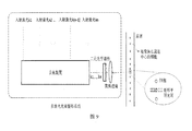
- FIG. 1 is a schematic structural view of a multi-laser beam shaping system for flow detection according to an embodiment of the present invention
- FIG. 2 is a schematic diagram of a mechanism of a multi-laser beam shaping system according to an embodiment of the present invention
- FIG. 3 is a schematic diagram showing the design of a binary optical device outputting a single rectangular flat top spot of 30 ⁇ m ⁇ 10 ⁇ m according to an embodiment of the present invention
- FIG. 4 is a schematic diagram showing the design of a binary optical device outputting a single rectangular flat-topped spot of 30 ⁇ m ⁇ 10 ⁇ m and the position of the spot away from the zero-order position according to an embodiment of the invention
- FIG. 5 is a schematic diagram of a binary optic design of a double rectangular flat-topped spot having an output size of 30 ⁇ m ⁇ 10 ⁇ m and a distance of 20 ⁇ m according to an embodiment of the present invention
- FIG. 6 is a schematic diagram of designing an output of a 405 nm, 488 nm, 560 nm, and 640 nm four laser using a same binary optical device to shape, homogenize, and focus a multi-laser shaping system according to an embodiment of the present invention
- FIG. 7 is a schematic diagram of designing an output of a 488 nm, 560 nm, and 640 nm three-color laser by using the same binary optical device to shape, homogenize, and focus a multi-laser shaping system according to an embodiment of the present invention
- FIG. 8 is a schematic diagram of designing an output of a 488 nm and 640 nm two-color laser using a same binary optical device for shaping, homogenizing, and focusing in a multi-laser shaping system for flow detection according to an embodiment of the present invention
- FIG. 9 is a schematic diagram of a multiple laser beam shaping system with a focusing lens, in accordance with one embodiment of the present invention.
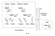
- FIG. 10 is a schematic diagram of a multi-laser beam shaping system for flow detection for shaping lasers separately according to an embodiment of the present invention
- FIG. 11 is a schematic diagram showing the formation of different rectangular flat-top spots by laser shaping of the respective lasers in the multi-laser beam shaping system for flow detection according to an embodiment of the present invention
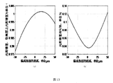
- FIG. 12 is a schematic view showing a 30 ⁇ m ⁇ 10 ⁇ m rectangular flat-top spot generated at a focal length of 10 mm according to an embodiment of the present invention, in which the spot amplitude and uniformity change with the off-focus surface;
- FIG. 12 is a schematic view showing a 30 ⁇ m ⁇ 10 ⁇ m rectangular flat-top spot generated at a focal length of 10 mm according to an embodiment of the present invention, in which the spot amplitude and uniformity change with the off-focus surface;
- FIG. 13 is a schematic diagram of a 30 ⁇ m ⁇ 10 ⁇ m rectangular flat-top spot generated at a focal length of 40 mm according to an embodiment of the present invention, in which the spot amplitude and uniformity change with the off-focus surface;
- FIG. 13 is a schematic diagram of a 30 ⁇ m ⁇ 10 ⁇ m rectangular flat-top spot generated at a focal length of 40 mm according to an embodiment of the present invention, in which the spot amplitude and uniformity change with the off-focus surface;
- FIG. 14 is a schematic diagram showing the design of a binary optical device outputting a single rectangular spot having a flat top size of 65 ⁇ m ⁇ 1 ⁇ m according to an embodiment of the present invention
- 15 is a schematic diagram of a 488 nm, 560 nm, and 640 nm laser respectively shaped by a binary optical device in a multi-laser beam shaping system for flow detection according to an embodiment of the present invention to form different rectangular flat-topped spots;
- 16 is a flow chart of a multi-laser beam shaping method for flow detection in accordance with an embodiment of the present invention.
- a multi-laser beam shaping system for flow detection composed of a combining device and a binary optical device
- a dichroic color is used in a multi-laser beam shaping system for flow detection.
- the mirror realizes multi-laser combining
- c for multi-laser beam shaping system for flow detection, and adopts fiber-optic wavelength division multiplexer and collimating device to realize multi-laser combining
- Fig. 6-8 (a) is a single rectangular flat top spot design close to zero pole; (b) is a single rectangular flat top spot design far away from the zero pole; (c) is a double rectangular flat top spot;
- Fig. 14 (a) is phase modulation; (b) is a phase distribution of a virtual lens; (c) is a phase of a binary optical device; and (d) is an output spot amplitude distribution.
- a multi-laser beam shaping system and method for flow detection according to an embodiment of the present invention will be described below with reference to the accompanying drawings.
- a multi-laser beam shaping system for flow detection according to an embodiment of the present invention will be described with reference to the accompanying drawings. .
- the multi-laser beam shaping system 10 for flow detection includes: a combining device 100, Used to combine multiple lasers.
- the combining device 100 is used to combine the lasers of the respective colors into one way.
- the combining device 100 includes a plurality of dichroic mirrors for reflecting the multiple lasers to converge into a single laser.
- the beam combining device 100 further includes a wavelength division multiplexer and a collimator to combine the multiple lasers into a single laser.
- the laser beams of the respective colors are first merged into one path by the above-described combining device 100.
- This embodiment can realize the combination of multiple lasers by different methods.
- the multi-laser beam shaping system 10 for flow detection in FIG. 2(b) uses a dichroic mirror, which is used in FIG. 2(c).
- the multi-laser beam shaping system 10 for flow detection uses a fiber-optic wavelength division multiplexer and a collimating device.
- the multi-laser beam shaping system 10 for flow detection of the present invention further includes: a binary optical device 200 having a surface relief structure for shaping the combined multicolor laser or monochromatic laser It is homogenized into a rectangular flat-top spot and controls the size and spatial position of the rectangular flat-top spot to detect single-cell flow flowing along the centerline of the flow channel.
- the binary optics 200 varies the optical path difference at each point of the incident light based on the Fraunhofer diffraction principle to modulate the phase of the incident light and produce a desired rectangular flat top on the output plane. Spot and control the size and spatial position of the rectangular flat top spot.
- the core of the multi-laser beam shaping system 10 for flow detection is a binary optics 200 that is capable of accurately controlling the size, shape and spatial position of the spot.
- the input plane is (x, y)
- the incident light is A(x, y)exp[i ⁇ (x, y)]
- the introduced phase is ⁇ BOE (x, y), through binary optics.
- the phase ⁇ BOE (x, y) is equal to the phase modulation ⁇ A (x, y).
- the binary optics 200 is capable of both shaping and homogenizing the spot.
- the binary optical device 200 is also used for beam focusing to function as a focus lens.
- the introduced phase ⁇ BOE (x, y) becomes the sum of the phase modulation ⁇ A (x, y) and the modulation effect of the lens on the phase ⁇ f (x, y) to form a virtual focus lens, such that
- the element optics 200 is capable of both shaping and homogenizing the spot and enabling lens accumulation.
- the incident light be a single-mode Gaussian beam with a beam diameter of 3 mm, and the focal length of the focusing lens is 10 mm.
- Design three outputs design one is a single rectangular flat top spot of 30 ⁇ m ⁇ 10 ⁇ m; design two is still a single rectangular flat top spot of 30 ⁇ m ⁇ 10 ⁇ m, but the output spot is farther away from the zero pole position than the design one, both in the output plane The position of (0,0); design three is two double rectangular flat-top spots of 30 ⁇ m ⁇ 10 ⁇ m and separated by 20 ⁇ m.
- the single rectangular spot has the smallest size, which is beneficial for increasing the maximum detection throughput per unit time.
- the double-rectangular spot enables multiple exposures to individual cells and prolongs the illumination time while ensuring spatial resolution, thereby enabling real-time speed measurement of individual cells and improving sensitivity and stability of detection.
- the size of the designed binary optical device 200 is 6 mm ⁇ 6 mm, the number of step units is 256 ⁇ 256, and the design wavelength is 488 nm.
- the subgraph (a) in Fig. 3 - Fig. 5 is the designed modulation phase ⁇ A (x, y), and the subgraph (b) in Fig. 3 - Fig. 5 is the phase distribution ⁇ of the virtual lens having a focal length of 10 mm.
- sub-graph (c) in Figures 3 - 5 is the phase ⁇ BOE (x, y) of the final binary optics 200 obtained by combining the two
- Sub-picture (d) is the output spot of the binary optics 200.
- the uniformity of the output spot can be expressed by the relative root mean square error of the spot amplitude.
- the uniformity of the three spots in the subgraph (d) in Figure 3-5 is 2.1%, 2.3% and 2.5%, respectively. More than 85%.
- the binary optics 200 is capable of shaping the laser into a rectangular flat-top spot with precise dimensions, sharp boundaries, position control, and variable shape.
- the multi-laser shaping effect of the system is examined.
- the four laser wavelengths commonly used in flow detection are 405 nm, 488 nm, 560 nm, and 640 nm.
- the uniformity of the output spot is represented by the relative root mean square error of the spot amplitude.
- the size of the spot formed by the laser of each color wavelength is proportional to the wavelength of the spot formed by the design wavelength, and the spatial position is also the same.
- the input lasers are 405 nm, 488 nm, 560 nm, and 640 nm, respectively, and the spatial positions of the spots formed by the four lasers coincide, as shown in Figure 6: For a single rectangular flat-top spot design close to the zero pole, the design wavelength is selected.
- the amplitude uniformity of the spots formed by the four incident wavelength lasers is 2.9%, 2.3%, 1.9%, and 2.3%, respectively, and the spatial positions of the respective spots coincide with each other; for a single rectangular flat-top spot design far away from the zero pole
- the design wavelength is 535 nm, and the amplitude uniformity of the spots formed by the four incident wavelength lasers are 3.8%, 2.5%, 2.3%, and 3.2%, respectively, and the spatial positions of the respective spots are separated from each other;
- the design wavelength is 569 nm, and the amplitude uniformity of the spots formed by the four incident wavelength lasers are 6.0%, 3.8%, 2.5%, and 5.3%, respectively.
- the input lasers are 488 nm, 560 nm, and 640 nm, respectively, and the design wavelength of the binary optics 200 is 567 nm, as shown in Fig. 7: for a single rectangular flat-top spot design close to the zero pole, the design wavelength is 580 nm.
- the amplitude uniformity of the spots formed by the three incident wavelength lasers is 2.4%, 2.0% and 2.2%, respectively, and the spatial positions of the respective spots coincide with each other; for the single rectangular flat-top spot design far away from the zero pole, the design wavelength is selected to be 566nm.
- the amplitude uniformity of the spots formed by the three incident wavelength lasers is 2.8%, 2.3% and 2.7%, respectively, and the spatial positions of the respective spots are separated from each other; for the output of the double rectangular flat-top spot, the design wavelength is selected to be 584 nm, three The amplitude uniformity of the spots formed by the incident wavelength lasers is 5.0%, 2.4%, and 3.2%, respectively. In the third case, the input lasers are 488 nm and 640 nm, respectively.
- Figure 8 For a single rectangular flat-top spot design close to the zero pole, select the design wavelength of 593 nm, the amplitude uniformity of the spot formed by the two incident wavelength lasers. The spatial positions of the spots are coincident with each other at 2.5% and 2.1% respectively.
- the design wavelength is 573 nm, and the amplitude uniformity of the spots formed by the two incident wavelength lasers is 2.9% and 2.6%, the spatial positions of the various spots are separated from each other; for the output of the double-rectangular flat-top spot, the design wavelength is 573 nm, and the amplitude uniformity of the spots formed by the two incident wavelength lasers is 4.2% and 2.5%, respectively. .
- the input laser is one of 405 nm, 488 nm, 560 nm, and 640 nm
- the design wavelength of the binary optical device 200 is equal to the input wavelength
- the wavelength of 488 nm is taken as an example
- the output spot is as shown in FIG. 3 to FIG. 5.
- this embodiment illustrates the multi-laser beam shaping system 10 for flow detection of the present invention, which can simultaneously realize shaping, homogenization and focusing of multi-color or monochromatic lasers to form accurate dimensions, clear boundaries, and position.
- Controllable and variable-shaped rectangular flat-top spot, each relative position of each multi-color laser spot can be controlled to be coincident or non-coincident, which can maintain excellent spot uniformity under the condition of multi-color laser incidence, and can greatly simplify the flow. Detect the required optical system and improve system stability.
- the multi-laser beam shaping system 10 for flow detection as shown in FIG. 9, the laser beams of the respective colors are reflected by the dichroic mirror and then merged into one path, and then passed through the binary optical device 200. It is shaped, homogenized and passed through a focusing lens to finally form the desired rectangular flat-top spot on the focal plane of the lens.
- This embodiment is similar to Embodiment 1 except that the phase ⁇ BOE (x, y) of the binary optical device 200 contains only the modulation phase ⁇ A (x, y) and no longer includes the virtual lens phase ⁇ f (x, y). ), the focusing function is done by a real, discrete lens.
- the multi-laser beam shaping system 10 for flow detection in this embodiment is equivalent to the system in Embodiment 1, and thus the shaping effect thereof will not be described.
- the multi-laser beam shaping system 10 for flow detection as shown in FIG. 10, the respective color lasers are respectively shaped and homogenized by the binary optical device 200, and the rear dichroic mirror After reflection, they converge into one way and pass through a focusing lens, eventually forming the desired rectangular flat-top spot on the focal plane of the lens.
- the system is characterized by being able to separately shape each laser, and can flexibly adjust the size, shape and spatial position of each laser output spot.
- the uniformity of the output spot is represented by the relative root mean square error of the spot amplitude.
- the binary optical device 200 is single or multiple, wherein when the binary optical device 200 is plural, each binary optical device 200 is disposed in one-to-one correspondence with each laser to each channel.
- the laser is individually shaped. For example, as shown in FIG. 11(a), for 405 nm, 488 nm, 560 nm, and 640 nm four-way laser shaping, the incident light is a single-mode Gaussian beam with a beam diameter of 3 mm, and the focal length of the focusing lens is 10 mm, and four binary optical devices 200 are designed.
- the spot uniformity was 3.3%, 2.1%, 2.0% and 1.9%, respectively.
- the incident light is a single-mode Gaussian beam with a beam diameter of 3 mm
- the focal length of the focusing lens is 10 mm
- four binary optical devices 200 are designed.
- four rectangular flat-top spots with different sizes and different distances are generated on the focal plane.
- the spot sizes are 30 ⁇ m ⁇ 5 ⁇ m, 30 ⁇ m ⁇ 10 ⁇ m, 40 ⁇ m ⁇ 10 ⁇ m and 50 ⁇ m ⁇ 10 ⁇ m, respectively.
- the incident light is a single-mode Gaussian beam with a beam diameter of 3mm, and the focal length of the focusing lens is 10mm.
- Two binary optics 200 are designed on the focal plane.
- the 640 nm laser is focused into a central, 30 ⁇ m ⁇ 10 ⁇ m rectangular flat-top spot, and the 488 nm laser is focused into two 30 ⁇ m ⁇ 10 ⁇ m rectangular flat-topped spots at 100 ⁇ m apart from each other on the upper and lower sides.
- the uniformity of the two spots is respectively It is 2.0% and 1.9%.
- This embodiment illustrates the multi-laser beam shaping system 10 for flow detection of the present invention, which can respectively shape each laser, and can flexibly adjust the size, shape and spatial position of each laser output spot to generate excellent uniformity.
- the multi-laser beam shaping system 10 for flow detection of the present invention can increase the focal length of the virtual lens of the binary optical device 200 or the depth of focus of the deepening spot of the solid lens. .
- the incident light is a single-mode Gaussian laser with a beam diameter of 3 mm and 488 nm, respectively, with focal lengths of 10 mm and 40 mm, and a rectangular flat-topped spot with a design output of 30 ⁇ m ⁇ 10 ⁇ m.
- the uniformity of the output spot is represented by the relative root mean square error of the spot amplitude. .
- the focal depth of the output spot is ⁇ 4.5 ⁇ m with a focal length of 10 mm, and the absolute depth of focus is 9 ⁇ m, and the amplitude of the spot on the boundary is compared.
- the amplitude of the spot on the focal plane changes by less than 3%; as shown in Fig. 13, if the uniformity of the spot is more than 10%, the focal depth of the output spot is ⁇ 40 ⁇ m at a focal length of 40 mm, and the absolute value of the depth of focus is greater than 80 ⁇ m.
- the amplitude of the spot on the boundary is less than 2% compared to the amplitude of the spot on the focal plane; as shown in FIG. 13, even if the spot uniformity exceeds 5%, the focal spot of the spot is output at a focal length of 40 mm.
- the depth can also reach -13 ⁇ m to 18 ⁇ m, the absolute value of the depth of focus is greater than 30 ⁇ m, and the amplitude of the spot on the boundary changes by less than 0.5% compared to the amplitude of the spot on the focal plane.
- the short side length of the output spot flat top is reduced to 0.9 ⁇ m, the long side length is 65 ⁇ m, and the spot position is offset from the zero pole by 200 ⁇ m.
- the focal length is 40mm, and the design wavelength is 560nm.
- the phase of the designed binary optics is shown in Figure 14.
- the flatness uniformity of the output spot is 1.1%. If the uniformity of the top of the spot exceeds 5%, the depth of focus is calculated. Up to 110 ⁇ m.
- the energy distribution in the short side direction of the spot is Gaussian, and the total length of the short side determined by the light intensity 1/e 2 times is 10 ⁇ m.
- the input laser includes 488 nm and 640 nm in addition to 560 nm
- the uniformity of the flat top of the spot is 1.1% and 1.2%, respectively
- the focal depths are 84 ⁇ m and 126 ⁇ m, respectively
- the size of the formed spot and the wavelength of 560 nm are as shown.
- the size of the spot formed is proportional to the wavelength.
- the combined laser is shaped and homogenized into a rectangular flat-top spot by binary optics, and the size and spatial position of the spot are accurately controlled, thereby detecting
- the single-cell flow along the midline of the flow channel achieves the purpose of improving the stability, resolution, signal-to-noise ratio, and throughput of the flow detection, and greatly simplifies the optical system and reduces the system volume.
- a multi-laser beam shaping method for flow detection includes the following steps: S101, combining multiple lasers; S102, combining multi-color lasers or singles The color laser is shaped and homogenized into a rectangular flat top spot; S103, which controls the size and spatial position of the rectangular flat top spot to detect a single cell flow flowing along the centerline of the flow channel.
- the multi-laser beam shaping method for flow detection according to the embodiment of the present invention, the combined laser is shaped and homogenized into a rectangular flat-top spot by binary optics, and the size and spatial position of the spot are accurately controlled, thereby detecting
- the single-cell flow flowing along the midline of the flow channel achieves the purpose of improving the stability, resolution, signal-to-noise ratio and flux detection of the flow detection, and greatly simplifies the optical system corresponding to the method and reduces the system volume.
- first and second are used for descriptive purposes only and are not to be construed as indicating or implying a relative importance or implicitly indicating the number of technical features indicated.
- features defining “first” or “second” may include at least one of the features, either explicitly or implicitly.
- the meaning of "a plurality” is at least two, such as two, three, etc., unless specifically defined otherwise.
- the terms “installation”, “connected”, “connected”, “fixed” and the like shall be understood broadly, and may be either a fixed connection or a detachable connection, unless explicitly stated and defined otherwise. , or integrated; can be mechanical or electrical connection; can be directly connected, or indirectly connected through an intermediate medium, can be the internal communication of two elements or the interaction of two elements, unless otherwise specified Limited.
- the specific meanings of the above terms in the present invention can be understood on a case-by-case basis.
- the first feature "on” or “below” the second feature may be the direct contact of the first and second features, or the first and second features may be indirectly through the intermediate medium, unless otherwise explicitly stated and defined. contact.
- the first feature "above”, “above” and “above” the second feature may be that the first feature is directly above or above the second feature, or merely that the first feature level is higher than the second feature.
- the first feature “below”, “below” and “below” the second feature may be that the first feature is directly below or obliquely below the second feature, or merely that the first feature level is less than the second feature.
Landscapes
- Physics & Mathematics (AREA)
- Chemical & Material Sciences (AREA)
- General Physics & Mathematics (AREA)
- Biochemistry (AREA)
- Life Sciences & Earth Sciences (AREA)
- Analytical Chemistry (AREA)
- Health & Medical Sciences (AREA)
- General Health & Medical Sciences (AREA)
- Dispersion Chemistry (AREA)
- Immunology (AREA)
- Pathology (AREA)
- Optics & Photonics (AREA)
- Investigating Or Analysing Materials By Optical Means (AREA)
Abstract
一种用于流式检测的多激光光束整形系统及方法,其中系统包括:合束装置(100),用于对多路激光进行合束;二元光学器件(200),二元光学器件(200)具有表面浮雕结构,以用于将合束后的多色激光或单色激光整形并均化为矩形平顶光斑,并控制矩形平顶光斑的尺寸和空间位置,以检测沿流道中线流动的单细胞流。该系统产生的矩形光斑尺寸精准、相对位置确定、边界清晰、顶部均匀,有利于提升流式检测的稳定性、分辨力、信噪比和检测通量,二元光学器件(200)还能够加入聚焦透镜的作用,同时完成对多色激光或单色激光的整形、匀化、定位和聚焦功能,并且极大地简化光学系统,减小系统体积。
Description
本发明涉及流式细胞检测技术领域,特别涉及一种用于流式检测的多激光光束整形系统及方法。
流式细胞仪是能够对细胞群体中每一个细胞的物理和化学信息进行多参数、高通量、并行检测的体外检测仪器,其检测对象除了细胞还包括蛋白、外泌体、核酸、病毒等生物微粒。流式细胞检测中,经过标记的单细胞首先在液流系统中被聚焦在微流道的中心位置,然后逐一被激光照射并发出荧光和散射光,而后这些光信号被收集和分析。在流式细胞仪中,多激光光束整形系统是流式检测的核心技术,其生成的激光光斑直接决定了检测的分辨力、灵敏度、稳定性、信噪比、最高通量等性能指标。
相关技术中心,现有的流式检测多采用椭圆形高斯光斑,这种光斑虽然成型容易,但是在光斑均匀性、分辨力、信噪比和检测一致性方面尚待提升,并且针对每一色激光需要单独进行整形,因而光学器件繁多,不利于提升系统的稳定性。在传统流式检测所用的激光整形系统中,每路激光在二向色镜和反射镜的帮助下汇聚为一路,之后各色激光经过一组光斑整形器件,如两个相互正交的柱透镜,而后被聚焦在流道中央,形成多个相互重叠的椭圆形高斯光斑,进而检测沿流道中线流动的单细胞流。有时,在光路中会添加多个棱镜,从而各色激光生成的光斑沿流道方向分开,防止光斑重叠。可见,传统的激光整形系统需要多个分立的光学器件,因而系统的稳定性较差、调节和安装难度大,同时无法准确地控制生成的椭圆形高斯光斑的尺寸和空间位置。
发明内容
本发明旨在至少在一定程度上解决相关技术中的技术问题之一。
为此,本发明的一个目的在于提出一种用于流式检测的多激光光束整形系统,该系统能够提升流式检测的稳定性、分辨力、信噪比和检测通量。
本发明的另一个目的在于提出一种用于流式检测的多激光光束整形方法。
为达到上述目的,本发明一方面实施例提出了一种用于流式检测的多激光光束整形系统,包括合束装置,用于对多路激光进行合束;二元光学器件,所述二元光学器件具有表面浮雕结构,以用于将合束后的单色或多色激光整形并均化为矩形平顶光斑,并控制所述 矩形平顶光斑的尺寸和空间位置,以检测沿流道中线流动的单细胞流。
本发明实施例的用于流式检测的多激光光束整形系统,通过二元光学器件将合束后的多色激光或单色激光整形并均化为矩形平顶光斑,精准地控制光斑的尺寸和空间位置,从而检测沿流道中线流动的单细胞流,达到提升流式检测的稳定性、分辨力、信噪比和检测通量的目的,并且极大地简化光学系统,减小系统体积。
另外,根据本发明上述实施例的用于流式检测的多激光光束整形系统还可以具有以下附加的技术特征:
进一步地,在本发明的实施例中,所述二元光学器件基于夫琅禾费衍射原理改变入射光各点处的光程差,以对所述入射光的相位进行调制并输出平面上产生期望的所述矩形平顶光斑,并控制所述矩形平顶光斑的尺寸和空间位置。
进一步地,在本发明的实施例中,用于流式检测的多激光光束整形系统,特征为,其中,输入平面为(x,y),入射光为A(x,y)exp[i·θ(x,y)],引入的相位为θ
BOE(x,y),通过二元光学之后的入射光为G(x,y)=A(x,y)exp[i·θ
BOE(x,y)+i·θ(x,y)],且所述引入的相位θ
BOE(x,y)与所述表面浮雕结构的高度h(x,y)的关系为:h(x,y)=λ/[2π(n-1)]×θ
BOE(x,y),其中,λ为激光波长,n为所述二元光学器件的折射率,以通过迭代算法解算出生成期望光斑U(u,v)的相位调制θ
A(x,y),其中(u,v)为输出平面,且引入的相位θ
BOE(x,y)等于相位调制θ
A(x,y)。
进一步地,在本发明的实施例中,所述二元光学器件还用于光束聚焦,其中,所述引入的相位θ
BOE(x,y)变为所述相位调制θ
A(x,y)和所述透镜对相位的调制作用θ
f(x,y)之和,以加入虚拟的聚焦透镜,起到聚焦的作用。
进一步地,在本发明的实施例中,通过增大所述二元光学器件的虚拟透镜的焦距加深光斑的焦深。
进一步地,在本发明的实施例中,所述合束装置包括:多个二向色镜,以对所述多路激光进行反射,以汇聚为单路激光。
进一步地,在本发明的实施例中,所述合束装置包括:波分复用器和准直器,以将多路激光合束为单路激光。
进一步地,在本发明的实施例中,所述二元光学器件为单个或多个,其中,当所述二元光学器件为多个时,每个二元光学器件与每路激光一一对应设置,以对所述每路激光进行单独整形。
进一步地,在本发明的实施例中,用于流式检测的多激光光束整形系统,还包括:聚焦透镜,具体为加入一个真实的聚焦透镜,使二元光学器件不加入聚焦功能,聚焦已经被二元光学器件相位调制后的激光。
为达到上述目的,本发明另一方面实施例提出了一种用于流式检测的多激光光束整形方法,包括以下步骤:对多路激光进行合束;将合束后的多色激光或单色激光整形并均化为矩形平顶光斑;以及控制所述矩形平顶光斑的尺寸和空间位置,以检测沿流道中线流动的单细胞流。
本发明实施例的用于流式检测的多激光光束整形方法,通过二元光学器件将合束后的激光整形并均化为矩形平顶光斑,精准地控制光斑的尺寸和空间位置,从而检测沿流道中线流动的单细胞流,达到提升流式检测的稳定性、分辨力、信噪比和检测通量的目的,并且极大地简化该方法对应系统的光学系统,减小系统体积。
本发明附加的方面和优点将在下面的描述中部分给出,部分将从下面的描述中变得明显,或通过本发明的实践了解到。
本发明上述的和/或附加的方面和优点从下面结合附图对实施例的描述中将变得明显和容易理解,其中:
图1为根据本发明实施例的用于流式检测的多激光光束整形系统的结构示意图;
图2为根据本发明一个实施例的多激光光束整形系统的机构示意图;
图3为根据本发明一个实施例的输出30μm×10μm单矩形平顶光斑的二元光学器件设计示意图;
图4为根据本发明一个实施例的输出30μm×10μm单矩形平顶光斑的二元光学器件设计及光斑远离零级位置示意图;
图5为根据本发明一个实施例的输出尺寸30μm×10μm且相距20μm的双矩形平顶光斑的二元光学器件设计示意图;
图6为根据本发明一个实施例的多激光整形系统中采用同一个二元光学器件对405nm、488nm、560nm和640nm四激光进行整形、匀化和聚焦,设计输出的示意图;
图7为根据本发明一个实施例的多激光整形系统中,采用同一个二元光学器件对488nm、560nm和640nm三色激光进行整形、匀化和聚焦,设计输出的示意图;
图8为根据本发明一个实施例的用于流式检测的多激光整形系统中,采用同一个二元光学器件对488nm和640nm双色激光进行整形、匀化和聚焦,设计输出的示意图;
图9为根据本发明一个实施例的带聚焦透镜的多激光光束整形系统的示意图;
图10为根据本发明一个实施例的对各路激光分别进行整形的用于流式检测的多激光光束整形系统示意图;
图11为根据本发明一个实施例的用于流式检测的多激光光束整形系统中各激光被二 元光学器件分别整形后形成不同的矩形平顶光斑的示意图;
图12为根据本发明一个实施例的焦距10mm时生成的30μm×10μm矩形平顶光斑,光斑幅值和均匀性随偏离焦面发生改变的情况的示意图;
图13为根据本发明一个实施例的焦距40mm时生成的30μm×10μm矩形平顶光斑,光斑幅值和均匀性随偏离焦面发生改变的情况的示意图;
图14为本发明一个实施例的输出为平顶尺寸65μm×1μm的单矩形光斑的二元光学器件设计示意图;
图15为本发明一个实施例的用于流式检测的多激光光束整形系统中488nm,560nm和640nm激光被二元光学器件分别整形后形成不同的矩形平顶光斑的示意图;和
图16为根据本发明实施例的用于流式检测的多激光光束整形方法的流程图。
附图标记说明:
图2中,(a)为用于流式检测的多激光光束整形系统由合束装置和二元光学器件组成;(b)为用于流式检测的多激光光束整形系统中采用二向色镜实现多激光合束(c)为用于流式检测的多激光光束整形系统中采用光纤波分复用器和准直器件实现多激光合束;
图3-5中,(a)为相位调制;(b)为虚拟透镜的相位分布;(c)为二元光学器件的相位;(d)为输出光斑幅值分布;
图6-8中,(a)为靠近零极的单矩形平顶光斑设计;(b)为远离零极的单矩形平顶光斑设计;(c)为双矩形平顶光斑;
图12中,(a)为光斑幅值的改变;(b)为光斑幅值均匀性的改变;
图14中,(a)为相位调制;(b)为虚拟透镜的相位分布;(c)为二元光学器件的相位;(d)为输出光斑幅值分布。
下面详细描述本发明的实施例,所述实施例的示例在附图中示出,其中自始至终相同或类似的标号表示相同或类似的元件或具有相同或类似功能的元件。下面通过参考附图描述的实施例是示例性的,旨在用于解释本发明,而不能理解为对本发明的限制。
下面参照附图描述根据本发明实施例提出的用于流式检测的多激光光束整形系统及方法,首先将参照附图描述根据本发明实施例提出的用于流式检测的多激光光束整形系统。
图1是根据本发明实施例的用于流式检测的多激光光束整形系统的结构示意图,如图1所示,该用于流式检测的多激光光束整形系统10包括:合束装置100,用于对多路激光进行合束。
在本发明的实施例中,合束装置100用于将各色激光合束为一路。其中,合束装置100包括:多个二向色镜,以对多路激光进行反射,以汇聚为单路激光。合束装置100还包括:波分复用器和准直器,以将多路激光合束为单路激光。
具体而言,在本发明的一个实施例中,如图2(a)所示,各色激光首先通过上述合束装置100被合束为一路。该实施例可以通过不同方法实现多路激光的合束,例如,图2(b)中的用于流式检测的多激光光束整形系统10采用二向色镜,图2(c)中的用于流式检测的多激光光束整形系统10采用的是光纤波分复用器和准直器件。
本发明的用于流式检测的多激光光束整形系统10还包括:二元光学器件200,二元光学器件200具有表面浮雕结构,以用于将合束后的多色激光或单色激光整形并均化为矩形平顶光斑,并控制矩形平顶光斑的尺寸和空间位置,以检测沿流道中线流动的单细胞流。
在本发明的一个实施例中,二元光学器件200基于夫琅禾费衍射原理改变入射光各点处的光程差,以对入射光的相位进行调制并输出平面上产生期望的矩形平顶光斑,并控制矩形平顶光斑的尺寸和空间位置。具体而言,该用于流式检测的多激光光束整形系统10的核心是二元光学器件200,其能够准确控制光斑的尺寸、形状和空间位置。具体而言,输入平面为(x,y),入射光为A(x,y)exp[i·θ(x,y)],引入的相位为θ
BOE(x,y),通过二元光学之后的入射光为G(x,y)=A(x,y)exp[i·θ
BOE(x,y)+i·θ(x,y)],且引入的相位θ
BOE(x,y)与表面浮雕结构的高度h(x,y)的关系为:h(x,y)=λ/[2π(n-1)]×θ
BOE(x,y),其中,λ为激光波长,n为二元光学器件200的折射率,以通过迭代算法解算出生成期望光斑U(u,v)的相位调制θ
A(x,y),其中(u,v)为输出平面,且引入的相位θ
BOE(x,y)等于相位调制θ
A(x,y)。这样,二元光学器件200既能够完成对光斑的整形和匀化。
进一步地,在本发明的实施例1中,二元光学器件200还用于光束聚焦,起到聚焦透镜的作用。其中,引入的相位θ
BOE(x,y)变为相位调制θ
A(x,y)和透镜对相位的调制作用θ
f(x,y)之和,以形成虚拟的聚焦透镜,这样,二元光学器件200既能够完成对光斑的整形和匀化又能够实现透镜聚集的功能。具体而言,在具体实施例中,还需要设计二元光学器件200的输出光斑形状。设入射光为光束直径3mm的单模高斯光束,聚焦透镜的焦距为10mm。设计三种输出:设计一为30μm×10μm的单矩形平顶光斑;设计二仍为30μm×10μm的单矩形平顶光斑,但相比设计一其输出光斑更加远离零极位置,既输出平面中(0,0)的位置;设计三为两个30μm×10μm且相距20μm的双矩形平顶光斑。单矩形光斑的尺寸最小,因而有利于提升单位时间内的最大检测通量。双矩形光斑能够在保证空间分辨率的情况下实现对单个细胞的多次照射并延长照射时间,因而能够实现对单个细胞的实时测速并提高检测的灵敏度和稳定性。设计的二元光学器件200的尺寸为6mm×6mm,台阶单元数量为256×256个,设计波长488nm。图3-图5中的子图(a)是经过设计所得的调制相位θ
A(x,y),图3- 图5中的子图(b)是焦距为10mm的虚拟透镜的相位分布θ
f(x,y),图3-图5中的子图(c)是将两者相结合后得到最终的二元光学器件200的相位θ
BOE(x,y),图3-图5中的子图(d)是二元光学器件200的输出光斑。输出光斑的均匀性可由光斑幅值的相对均方根误差表示,图3-图5中的子图(d)中三个光斑的均匀性分别为2.1%,2.3%和2.5%,能量效率均大于85%。由输出光斑可见,二元光学器件200能够将激光整形为尺寸精准、边界清晰、位置可控、形状可变的矩形平顶光斑。
进一步地,在本发明的一个实施例中,考察系统的多激光整形效果。流式检测中常用的四种激光波长为405nm、488nm、560nm和640nm,考虑四种输入光波长的组合情况,并以图3-图5中的设计为例。输出光斑的均匀性由光斑幅值的相对均方根误差表示。设计中,各色波长激光的所形成光斑的尺寸与设计波长的所形成光斑的尺寸相比正比于波长,空间位置也是如此。第一种情况下,输入激光分别为405nm、488nm、560nm和640nm,四种激光所形成光斑的的空间位置相重合,如图6:对于靠近零极的单矩形平顶光斑设计,选取设计波长为562nm,四种入射波长激光所形成的光斑的幅值均匀性分别为2.9%、2.3%、1.9%和2.3%,各个光斑的空间位置相互重合;对于远离零极的单矩形平顶光斑设计,选取设计波长为535nm,四种入射波长激光所形成的光斑的幅值均匀性分别为3.8%、2.5%、2.3%和3.2%,各个光斑的空间位置相互分离;对于输出的双矩形平顶光斑,选取设计波长为569nm,四种入射波长激光所形成的光斑的幅值均匀性分别为6.0%、3.8%、2.5%和5.3%。第二种情况下,输入激光分别为488nm、560nm和640nm,选取二元光学器件200的设计波长为567nm,如图7:对于靠近零极的单矩形平顶光斑设计,选取设计波长为580nm,三种入射波长激光所形成的光斑的幅值均匀性分别为2.4%、2.0%和2.2%,各个光斑的空间位置相互重合;对于远离零极的单矩形平顶光斑设计,选取设计波长为566nm,三种入射波长激光所形成的光斑的幅值均匀性分别为2.8%、2.3%和2.7%,各个光斑的空间位置相互分离;对于输出的双矩形平顶光斑,选取设计波长为584nm,三种入射波长激光所形成的光斑的幅值均匀性分别为5.0%、2.4%和3.2%。第三种情况下,输入激光分别为488nm和640nm,如图8:对于靠近零极的单矩形平顶光斑设计,选取设计波长为593nm,两种入射波长激光所形成的光斑的幅值均匀性分别为2.5%和2.1%,各个光斑的空间位置相互重合;对于远离零极的单矩形平顶光斑设计,选取设计波长为573nm,两种入射波长激光所形成的光斑的幅值均匀性分别为2.9%和2.6%,各个光斑的空间位置相互分离;对于输出的双矩形平顶光斑,选取设计波长为573nm,两种入射波长激光所形成的光斑的幅值均匀性分别为4.2%和2.5%。第四种情况下,输入激光为405nm、488nm、560nm和640nm中的某一种,选取二元光学器件200的设计波长等于输入波长,以488nm波长为例,其输出光斑如图3-图5中的子图(d)所示。
可以理解的是,该实施例说明了本发明用于流式检测的多激光光束整形系统10,能够同时实现多色或单色激光的整形、匀化和聚焦,形成尺寸精准、边界清晰、位置可控、形状可变的矩形平顶光斑,各个多色激光光斑的各相对位置可以控制为位置重合或不重合,能够在多色激光入射情况下保持优良的光斑均匀性,能够极大地简化流式检测所需的光学系统、提高系统稳定性。
此外,在本发明的实施例2中,用于流式检测的多激光光束整形系统10,如图9所示,各色激光被二向色镜反射后汇聚为一路,而后经过二元光学器件200被整形、匀化并经过一个聚焦透镜,最终在透镜的焦面上形成所需的矩形平顶光斑。该实施例与实施例1类似,区别在于二元光学器件200的相位θ
BOE(x,y)仅包含调制相位θ
A(x,y),而不再包含虚拟透镜相位θ
f(x,y),聚焦功能由一个真实、分立的透镜完成。该实施例中的用于流式检测的多激光光束整形系统10等效于实施例1中的系统,因而对其整形效果不再累述。
进一步地,在本发明的实施例3中,用于流式检测的多激光光束整形系统10,如图10所示,各色激光被二元光学器件200分别整形、匀化,而后二向色镜反射后汇聚为一路并经过一个聚焦透镜,最终在透镜的焦面上形成所需的矩形平顶光斑。该系统的特点在于能够对每一路激光分别整形,能够灵活调整每一路激光输出光斑的尺寸、形状和空间位置。输出光斑的均匀性由光斑幅值的相对均方根误差表示。再具体实施例中,二元光学器件200为单个或多个,其中,当二元光学器件200为多个时,每个二元光学器件200与每路激光一一对应设置,以对每路激光进行单独整形。例如图11(a)所示,对405nm、488nm、560nm和640nm四路激光整形,入射光为光束直径3mm的单模高斯光束,聚焦透镜的焦距为10mm,设计四个二元光学器件200,并在焦面上生成四个尺寸均为30μm×10μm的、相距20μm的矩形平顶光斑,光斑均匀性分别为3.3%、2.1%、2.0%和1.9%。例如图11(b)所示,对405nm、488nm、560nm和640nm四路激光整形,入射光为光束直径3mm的单模高斯光束,聚焦透镜的焦距为10mm,设计四个二元光学器件200,并在焦面上生成四个尺寸各不相同的、相距相聚距离各不相同的矩形平顶光斑,光斑尺寸分别为30μm×5μm、30μm×10μm、40μm×10μm和50μm×10μm,相距距离分别为10μm、20μm和30μm,均匀性分别为2.1%、2.1%、2.2%和2.0%。例如图11(c)所示,对488nm和640nm两路激光整形,入射光为光束直径3mm的单模高斯光束,聚焦透镜的焦距为10mm,设计两个二元光学器件200,在焦面上将640nm激光聚焦为一个位于中心的、30μm×10μm的矩形平顶光斑,将488nm激光聚焦为位于上下两侧的、两个相距100μm的30μm×10μm矩形平顶光斑,两个光斑的均匀性分别为2.0%和1.9%。
该实施例说明了本发明用于流式检测的多激光光束整形系统10,能够对每一路激光分别整形,能够灵活调整每一路激光输出光斑的尺寸、形状和空间位置,生成具有优异的均 匀性的、相分离的多个矩形平顶光斑。
进一步地,在本发明的实施例4中,本发明的用于流式检测的多激光光束整形系统10可以通过增大二元光学器件200的虚拟透镜的焦距或实体透镜的加深光斑的焦深。具体而言,通过增大系统中二元光学器件200虚拟透镜或实体透镜的焦距,能够加深光斑的焦深,从而提升检测的稳定性。入射光为光束直径3mm、488nm的单模高斯激光,分别采用焦距10mm和40mm,设计输出均为30μm×10μm的矩形平顶光斑,输出光斑的均匀性由光斑幅值的相对均方根误差表示。如图12所示,如果以光斑均匀性超过10%为界,则焦距10mm情况下输出光斑的的焦深为±4.5μm,焦深绝对值为9μm,且在边界上光斑的幅值相比于焦面上光斑的幅值变化小于3%;如图13所示,如果以光斑均匀性超过10%为界,在焦距40mm情况下输出光斑的焦深为±40μm,焦深绝对值大于80μm,且在边界上光斑的幅值相比于焦面上光斑的幅值变化小于2%;如图13所示,即使以光斑均匀性超过5%为界,在焦距40mm情况下输出光斑的焦深也可达到-13μm ~18μm,焦深绝对值大于30μm,且在边界上光斑的幅值相比于焦面上光斑的幅值变化小于0.5%。
进一步地,在本发明的实施例5中,为了进一步提高空间分辨率和增加焦深,减小输出光斑平顶的短边长度为0.9μm、长边长度65μm,光斑位置偏离零极上方200μm,焦距为40mm,取设计波长为560nm,设计的二元光学器件的相位如图14所示,输出光斑的平顶均匀性为1.1%,如果按照光斑顶部的均匀性超过5%计算则其焦深可达110μm。由于光斑平顶短轴尺寸短且焦距长,因而光斑短边方向的能量分布呈现高斯状,按照光强1/e
2倍确定的短边总长度为10μm。如图15所示,如果输入激光除了560nm还包括488nm和640nm,则光斑平顶的均匀性分别为1.1%和1.2%,焦深分别为84μm和126μm,所形成光斑的尺寸与560nm波长的所形成光斑的尺寸相比正比于波长。
本发明实施例的用于流式检测的多激光光束整形系统,通过二元光学器件将合束后的激光整形并均化为矩形平顶光斑,精准地控制光斑的尺寸和空间位置,从而检测沿流道中线流动的单细胞流,达到提升流式检测的稳定性、分辨力、信噪比和检测通量的目的,并且极大地简化光学系统,减小系统体积。
如图16所示,本发明一个实施例的用于流式检测的多激光光束整形方法,包括以下步骤:S101,对多路激光进行合束;S102,将合束后的多色激光或单色激光整形并均化为矩形平顶光斑;S103,控制矩形平顶光斑的尺寸和空间位置,以检测沿流道中线流动的单细胞流。
本发明实施例的用于流式检测的多激光光束整形方法,通过二元光学器件将合束后的激光整形并均化为矩形平顶光斑,精准地控制光斑的尺寸和空间位置,从而检测沿流道中线流动的单细胞流,达到提升流式检测的稳定性、分辨力、信噪比和检测通量的目的,并 且极大地简化该方法对应的光学系统,减小系统体积。
要说明的是,前述对方法实施例的用于流式检测的多激光光束整形系统解释说明也适用于该实施例的方法,此处不再赘述。
在本发明的描述中,需要理解的是,术语“中心”、“纵向”、“横向”、“长度”、“宽度”、“厚度”、“上”、“下”、“前”、“后”、“左”、“右”、“竖直”、“水平”、“顶”、“底”“内”、“外”、“顺时针”、“逆时针”、“轴向”、“径向”、“周向”等指示的方位或位置关系为基于附图所示的方位或位置关系,仅是为了便于描述本发明和简化描述,而不是指示或暗示所指的装置或元件必须具有特定的方位、以特定的方位构造和操作,因此不能理解为对本发明的限制。
此外,术语“第一”、“第二”仅用于描述目的,而不能理解为指示或暗示相对重要性或者隐含指明所指示的技术特征的数量。由此,限定有“第一”、“第二”的特征可以明示或者隐含地包括至少一个该特征。在本发明的描述中,“多个”的含义是至少两个,例如两个,三个等,除非另有明确具体的限定。
在本发明中,除非另有明确的规定和限定,术语“安装”、“相连”、“连接”、“固定”等术语应做广义理解,例如,可以是固定连接,也可以是可拆卸连接,或成一体;可以是机械连接,也可以是电连接;可以是直接相连,也可以通过中间媒介间接相连,可以是两个元件内部的连通或两个元件的相互作用关系,除非另有明确的限定。对于本领域的普通技术人员而言,可以根据具体情况理解上述术语在本发明中的具体含义。
在本发明中,除非另有明确的规定和限定,第一特征在第二特征 “上”或“下”可以是第一和第二特征直接接触,或第一和第二特征通过中间媒介间接接触。而且,第一特征在第二特征“之上”、“上方”和“上面”可是第一特征在第二特征正上方或斜上方,或仅仅表示第一特征水平高度高于第二特征。第一特征在第二特征“之下”、“下方”和“下面”可以是第一特征在第二特征正下方或斜下方,或仅仅表示第一特征水平高度小于第二特征。
在本说明书的描述中,参考术语“一个实施例”、“一些实施例”、 “示例”、“具体示例”、或“一些示例”等的描述意指结合该实施例或示例描述的具体特征、结构、材料或者特点包含于本发明的至少一个实施例或示例中。在本说明书中,对上述术语的示意性表述不必须针对的是相同的实施例或示例。而且,描述的具体特征、结构、材料或者特点可以在任一个或多个实施例或示例中以合适的方式结合。此外,在不相互矛盾的情况下,本领域的技术人员可以将本说明书中描述的不同实施例或示例以及不同实施例或示例的特征进行结合和组合。
尽管上面已经示出和描述了本发明的实施例,可以理解的是,上述实施例是示例性的,不能理解为对本发明的限制,本领域的普通技术人员在本发明的范围内可以对上述实施例 进行变化、修改、替换和变型。
Claims (10)
- 一种用于流式检测的多激光光束整形系统,其特征在于,包括以下步骤:合束装置,用于对多路激光进行合束;和二元光学器件,所述二元光学器件具有表面浮雕结构,以用于将合束后的多色激光或单色激光整形并均化为矩形平顶光斑,并控制所述矩形平顶光斑的尺寸和空间位置,以检测沿流道中线流动的单细胞流。
- 根据权利要求1所述的用于流式检测的多激光光束整形系统,其特征在于,所述二元光学器件基于夫琅禾费衍射原理改变入射光各点处的光程差,以对所述入射光的相位进行调制并输出平面上产生期望的所述矩形平顶光斑,并控制所述矩形平顶光斑的尺寸和空间位置。
- 根据权利要求2所述的用于流式检测的多激光光束整形系统,其特征在于,其中,输入平面为(x,y),入射光为A(x,y)exp[i·θ(x,y)],引入的相位为θ BOE(x,y),通过二元光学之后的入射光为G(x,y)=A(x,y)exp[i·θ BOE(x,y)+i·θ(x,y)],且所述引入的相位θ BOE(x,y)与所述表面浮雕结构的高度h(x,y)的关系为:h(x,y)=λ/[2π(n-1)]×θ BOE(x,y),其中,λ为激光波长,n为所述二元光学器件的折射率,以通过迭代算法解算出生成期望光斑U(u,v)的相位调制θ A(x,y),其中(u,v)为输出平面,且引入的相位θ BOE(x,y)等于相位调制θ A(x,y)。
- 根据权利要求3所述的用于流式检测的多激光光束整形系统,其特征在于,所述二元光学器件还用于光束聚焦,其中,所述引入的相位θ BOE(x,y)变为所述相位调制θ A(x,y)和所述透镜对相位的调制作用θ f(x,y)之和,以加入虚拟的聚焦透镜,起到聚焦透镜的作用。
- 根据权利要求4所述的用于流式检测的多激光光束整形系统,其特征在于,通过增大所述二元光学器件的虚拟透镜或实体透镜的的焦距加深光斑的焦深。
- 根据权利要求1所述的用于流式检测的多激光光束整形系统,其特征在于,所述合束装置包括:多个二向色镜,以对所述多路激光进行反射,以汇聚为单路激光。
- 根据权利要求1所述的用于流式检测的多激光光束整形系统,其特征在于,所述合束装置包括:波分复用器和准直器,以将多路激光合束为单路激光。
- 根据权利要求1所述的用于流式检测的多激光光束整形系统,其特征在于,所述二元光学器件为单个或多个,其中,当所述二元光学器件为多个时,每个二元光学器件与每路激光一一对应设置,以对所述每路激光进行单独整形。
- 根据权利要求1或8的用于流式检测的多激光光束整形系统,其特征在于,还包括:聚焦透镜,具体为加入一个真实的聚焦透镜,使二元光学器件不加入聚焦功能,聚焦已经被二元光学器件相位调制后的激光。
- 一种用于流式检测的多激光光束整形方法,其特征在于,包括以下步骤:对多路激光进行合束;将合束后的单色或多色激光整形并均化为矩形平顶光斑;以及控制所述矩形平顶光斑的尺寸和空间位置,以检测沿流道中线流动的单细胞流。
Priority Applications (1)
| Application Number | Priority Date | Filing Date | Title |
|---|---|---|---|
| PCT/CN2018/083232 WO2019200518A1 (zh) | 2018-04-16 | 2018-04-16 | 用于流式检测的多激光光束整形系统及方法 |
Applications Claiming Priority (1)
| Application Number | Priority Date | Filing Date | Title |
|---|---|---|---|
| PCT/CN2018/083232 WO2019200518A1 (zh) | 2018-04-16 | 2018-04-16 | 用于流式检测的多激光光束整形系统及方法 |
Publications (1)
| Publication Number | Publication Date |
|---|---|
| WO2019200518A1 true WO2019200518A1 (zh) | 2019-10-24 |
Family
ID=68240486
Family Applications (1)
| Application Number | Title | Priority Date | Filing Date |
|---|---|---|---|
| PCT/CN2018/083232 Ceased WO2019200518A1 (zh) | 2018-04-16 | 2018-04-16 | 用于流式检测的多激光光束整形系统及方法 |
Country Status (1)
| Country | Link |
|---|---|
| WO (1) | WO2019200518A1 (zh) |
Citations (5)
| Publication number | Priority date | Publication date | Assignee | Title |
|---|---|---|---|---|
| US20150077869A1 (en) * | 2013-09-17 | 2015-03-19 | Coherent, Inc. | Apparatus for delivery of laser-beams of different wavelengths to a flow-cytometer |
| CN104503101A (zh) * | 2015-01-12 | 2015-04-08 | 清华大学 | 一种基于衍射光学整形器件的流式细胞仪光束形成系统 |
| CN105987870A (zh) * | 2015-02-10 | 2016-10-05 | 博奥生物集团有限公司 | 一种流式细胞分选系统及其聚焦检测方法及其流体芯片 |
| CN106383081A (zh) * | 2016-08-22 | 2017-02-08 | 清华大学 | 基于二元光学器件的微流体芯片自动对准方法和系统 |
| CN108646422A (zh) * | 2018-04-16 | 2018-10-12 | 清华大学 | 用于流式检测的多激光光束整形系统及方法 |
-
2018
- 2018-04-16 WO PCT/CN2018/083232 patent/WO2019200518A1/zh not_active Ceased
Patent Citations (5)
| Publication number | Priority date | Publication date | Assignee | Title |
|---|---|---|---|---|
| US20150077869A1 (en) * | 2013-09-17 | 2015-03-19 | Coherent, Inc. | Apparatus for delivery of laser-beams of different wavelengths to a flow-cytometer |
| CN104503101A (zh) * | 2015-01-12 | 2015-04-08 | 清华大学 | 一种基于衍射光学整形器件的流式细胞仪光束形成系统 |
| CN105987870A (zh) * | 2015-02-10 | 2016-10-05 | 博奥生物集团有限公司 | 一种流式细胞分选系统及其聚焦检测方法及其流体芯片 |
| CN106383081A (zh) * | 2016-08-22 | 2017-02-08 | 清华大学 | 基于二元光学器件的微流体芯片自动对准方法和系统 |
| CN108646422A (zh) * | 2018-04-16 | 2018-10-12 | 清华大学 | 用于流式检测的多激光光束整形系统及方法 |
Similar Documents
| Publication | Publication Date | Title |
|---|---|---|
| CN108646422B (zh) | 用于流式检测的多激光光束整形系统及方法 | |
| JP4974206B2 (ja) | 光線ビームの対称化及び均一化の複合機能素子 | |
| CN107941763B (zh) | 一种共轴三维受激辐射损耗超分辨显微成像方法和装置 | |
| CN110907415B (zh) | 一种基于并行探测的三维亚十纳米定位方法及装置 | |
| CN103424861B (zh) | 基于柱偏振涡旋光束的超分辨共焦显微成像方法及装置 | |
| CN217639718U (zh) | 一种接收系统及显微镜 | |
| JP6234105B2 (ja) | 超解像顕微鏡 | |
| CN100523716C (zh) | 复色超分辨差动共焦测量方法与装置 | |
| CN112485232B (zh) | 基于一维暗斑分时照明的亚十纳米定位测向方法和装置 | |
| CN102096180A (zh) | 超分辨率显微镜 | |
| CN107861230B (zh) | 变焦光镊共聚焦显微成像装置及方法 | |
| CN102566076B (zh) | 多焦点光束产生装置及多焦点共焦扫描显微镜 | |
| CN103424859A (zh) | 基于柱矢量光束的受激发射损耗显微成像方法及装置 | |
| CN108845409A (zh) | 一种基于多面体棱镜产生阵列多焦点的装置及方法 | |
| CN108802988A (zh) | 超分辨光学显微成像系统及其调节方法 | |
| Zhou et al. | Computational localization microscopy with extended axial range | |
| CN102122079A (zh) | 受激发射损耗显微镜中抑制光斑的生成方法和装置 | |
| CN102122080A (zh) | 一种受激发射损耗显微镜中抑制光斑的生成方法及装置 | |
| US20220057615A1 (en) | Method and device for illuminating a sample in a microscope in points | |
| CN111221122B (zh) | 较大视场强容差超分辨望远成像系统设计方法 | |
| CN110908100B (zh) | 光谱分辨高分辨率3d定位显微术 | |
| CN103885186A (zh) | 一种基于棱镜对和柱面镜的消像散光束整形系统 | |
| CN112305741B (zh) | 一种轴向多焦点光学系统 | |
| Ortkrass et al. | Grazing incidence to total internal reflection fluorescence structured illumination microscopy enabled by a prism telescope | |
| CN222734335U (zh) | 一种光学组件以及光谱相机 |
Legal Events
| Date | Code | Title | Description |
|---|---|---|---|
| 121 | Ep: the epo has been informed by wipo that ep was designated in this application |
Ref document number: 18915498 Country of ref document: EP Kind code of ref document: A1 |
|
| NENP | Non-entry into the national phase |
Ref country code: DE |
|
| 122 | Ep: pct application non-entry in european phase |
Ref document number: 18915498 Country of ref document: EP Kind code of ref document: A1 |