WO2019198756A1 - 複合発電プラント - Google Patents
複合発電プラント Download PDFInfo
- Publication number
- WO2019198756A1 WO2019198756A1 PCT/JP2019/015618 JP2019015618W WO2019198756A1 WO 2019198756 A1 WO2019198756 A1 WO 2019198756A1 JP 2019015618 W JP2019015618 W JP 2019015618W WO 2019198756 A1 WO2019198756 A1 WO 2019198756A1
- Authority
- WO
- WIPO (PCT)
- Prior art keywords
- steam
- boiler
- exhaust gas
- heat
- steam turbine
- Prior art date
- Legal status (The legal status is an assumption and is not a legal conclusion. Google has not performed a legal analysis and makes no representation as to the accuracy of the status listed.)
- Ceased
Links
Images
Classifications
-
- F—MECHANICAL ENGINEERING; LIGHTING; HEATING; WEAPONS; BLASTING
- F01—MACHINES OR ENGINES IN GENERAL; ENGINE PLANTS IN GENERAL; STEAM ENGINES
- F01K—STEAM ENGINE PLANTS; STEAM ACCUMULATORS; ENGINE PLANTS NOT OTHERWISE PROVIDED FOR; ENGINES USING SPECIAL WORKING FLUIDS OR CYCLES
- F01K23/00—Plants characterised by more than one engine delivering power external to the plant, the engines being driven by different fluids
- F01K23/02—Plants characterised by more than one engine delivering power external to the plant, the engines being driven by different fluids the engine cycles being thermally coupled
- F01K23/06—Plants characterised by more than one engine delivering power external to the plant, the engines being driven by different fluids the engine cycles being thermally coupled combustion heat from one cycle heating the fluid in another cycle
- F01K23/10—Plants characterised by more than one engine delivering power external to the plant, the engines being driven by different fluids the engine cycles being thermally coupled combustion heat from one cycle heating the fluid in another cycle with exhaust fluid of one cycle heating the fluid in another cycle
-
- F—MECHANICAL ENGINEERING; LIGHTING; HEATING; WEAPONS; BLASTING
- F02—COMBUSTION ENGINES; HOT-GAS OR COMBUSTION-PRODUCT ENGINE PLANTS
- F02C—GAS-TURBINE PLANTS; AIR INTAKES FOR JET-PROPULSION PLANTS; CONTROLLING FUEL SUPPLY IN AIR-BREATHING JET-PROPULSION PLANTS
- F02C6/00—Plural gas-turbine plants; Combinations of gas-turbine plants with other apparatus; Adaptations of gas-turbine plants for special use
- F02C6/18—Plural gas-turbine plants; Combinations of gas-turbine plants with other apparatus; Adaptations of gas-turbine plants for special use using the waste heat of gas-turbine plants outside the plants themselves, e.g. gas-turbine power heat plants
-
- F—MECHANICAL ENGINEERING; LIGHTING; HEATING; WEAPONS; BLASTING
- F22—STEAM GENERATION
- F22B—METHODS OF STEAM GENERATION; STEAM BOILERS
- F22B1/00—Methods of steam generation characterised by form of heating method
- F22B1/02—Methods of steam generation characterised by form of heating method by exploitation of the heat content of hot heat carriers
- F22B1/18—Methods of steam generation characterised by form of heating method by exploitation of the heat content of hot heat carriers the heat carrier being a hot gas, e.g. waste gas such as exhaust gas of internal-combustion engines
-
- Y—GENERAL TAGGING OF NEW TECHNOLOGICAL DEVELOPMENTS; GENERAL TAGGING OF CROSS-SECTIONAL TECHNOLOGIES SPANNING OVER SEVERAL SECTIONS OF THE IPC; TECHNICAL SUBJECTS COVERED BY FORMER USPC CROSS-REFERENCE ART COLLECTIONS [XRACs] AND DIGESTS
- Y02—TECHNOLOGIES OR APPLICATIONS FOR MITIGATION OR ADAPTATION AGAINST CLIMATE CHANGE
- Y02E—REDUCTION OF GREENHOUSE GAS [GHG] EMISSIONS, RELATED TO ENERGY GENERATION, TRANSMISSION OR DISTRIBUTION
- Y02E20/00—Combustion technologies with mitigation potential
- Y02E20/16—Combined cycle power plant [CCPP], or combined cycle gas turbine [CCGT]
-
- Y—GENERAL TAGGING OF NEW TECHNOLOGICAL DEVELOPMENTS; GENERAL TAGGING OF CROSS-SECTIONAL TECHNOLOGIES SPANNING OVER SEVERAL SECTIONS OF THE IPC; TECHNICAL SUBJECTS COVERED BY FORMER USPC CROSS-REFERENCE ART COLLECTIONS [XRACs] AND DIGESTS
- Y02—TECHNOLOGIES OR APPLICATIONS FOR MITIGATION OR ADAPTATION AGAINST CLIMATE CHANGE
- Y02E—REDUCTION OF GREENHOUSE GAS [GHG] EMISSIONS, RELATED TO ENERGY GENERATION, TRANSMISSION OR DISTRIBUTION
- Y02E60/00—Enabling technologies; Technologies with a potential or indirect contribution to GHG emissions mitigation
- Y02E60/30—Hydrogen technology
- Y02E60/50—Fuel cells
Definitions
- the present invention relates to a combined power plant.
- Patent Document 1 As a waste heat recovery boiler used in a combined power generation system, a superheater that generates superheated steam to be supplied to the steam turbine and a reheater that reheats the steam discharged from the steam turbine for the purpose of improving power generation efficiency, etc. are known (for example, Patent Document 1).
- the reheat-type exhaust heat recovery boiler described in Patent Document 1 includes a superheater that superheats the main steam and a reheater that heats the reheat steam.
- the superheater is connected to a high-pressure steam turbine constituting a part of the reheat-type steam turbine by a main steam pipe, and exhaust from the high-pressure steam turbine is provided in the exhaust heat recovery boiler via a low-temperature reheat steam pipe. Then, the steam guided to the reheater and heated by the reheater is introduced into a reheat turbine constituting a part of the reheat type steam turbine through a high temperature reheat steam pipe.
- a pipe connecting the superheater and the steam turbine and a pipe connecting the reheater and the steam turbine may be long.
- the piping connecting the superheater and the steam turbine, and the piping connecting the reheater and the steam turbine, the steam heated by the heat of the exhaust gas circulates and becomes high temperature, so the material with excellent heat resistance performance with high material unit price Need to be configured. Therefore, there is a possibility that the manufacturing cost of the combined power plant increases due to the length of such piping.
- This invention is made
- a combined power plant of the present invention employs the following means.
- a combined power plant according to one aspect of the present invention includes a first boiler having one or more heat engines or fuel cells, and a first heat exchanger that heats steam by heat of exhaust gas from the heat engines or fuel cells.
- the first steam turbine driven by the steam heated by the first boiler, the first heat exchanger and the first steam turbine are connected, and the steam heated by the first boiler is converted to the first steam.
- the second boiler, the second steam turbine driven by the steam heated by the second boiler, the second heat exchanger and the second steam turbine are connected, and the steam heated by the second boiler is And a, a second steam pipe leading to serial second steam turbine.
- the first boiler having the first heat exchanger and the second boiler having the second heat exchanger are constituted by different boilers.
- each boiler can be reduced in size compared with the structure which provides a 1st heat exchanger and a 2nd heat exchanger in one boiler. Therefore, the boiler which comprises a combined power plant can be installed easily.
- each boiler can be reduced in size, the freedom degree on the layout in the arrangement
- positioning of a boiler can be improved. Therefore, for example, a boiler constituting a combined power plant can be installed even in a narrow space and complicated space or topography.
- the 1st boiler which has a 1st heat exchanger, and the 2nd boiler which has a 2nd heat exchanger are comprised by another boiler, a 1st heat exchanger and a 2nd heat exchanger are made into one.
- the number of heat exchangers provided in each boiler is small.
- the freedom degree on a layout can be improved about arrangement
- the length of the steam pipe can be shortened. Cost can be reduced by the shortened amount.
- the heat engine or fuel cell that discharges the exhaust gas supplied to the first boiler and the heat engine or fuel cell that discharges the exhaust gas supplied to the second boiler may be the same heat engine or fuel cell. It may be another heat engine or a fuel cell.
- the first boiler and the first steam turbine may be disposed adjacent to each other.
- the first steam pipe Since the steam heated by the heat of the exhaust gas flows, the first steam pipe needs to be made of a material having excellent heat resistance. For this reason, the first steam pipe has a relatively high cost per unit length.
- the first boiler and the first steam turbine are disposed adjacent to each other. Thereby, the 1st steam piping which connects the 1st heat exchanger and the 1st steam turbine can be shortened. Therefore, since the pipe length of the relatively expensive first steam pipe can be shortened, the cost can be greatly reduced.
- a combined power plant includes a third heat exchanger that heats steam discharged from the second steam turbine by heat of exhaust gas from the heat engine or a fuel cell, and the first boiler. And a third boiler different from the second boiler, a third steam turbine driven by steam heated by the third boiler, the third heat exchanger, and the third steam turbine, A third steam pipe for guiding the steam generated in the three boilers to the third steam turbine, and a fourth heat exchange for heating the steam discharged from the third steam turbine by heat of exhaust gas from the heat engine or the fuel cell.
- a fourth boiler different from the first boiler, the second boiler, and the third boiler, a fourth steam turbine driven by steam heated by the fourth boiler, and the fourth boiler And connecting the the exchanger fourth steam turbine, the steam generated in the fourth boiler and a fourth steam pipe leading to the fourth steam turbine may be provided.
- the 3rd boiler which has a 3rd heat exchanger, and the 4th boiler which has a 4th heat exchanger are comprised by another boiler and another boiler.
- the freedom degree on a layout can be improved about arrangement
- the combined power plant according to an aspect of the present invention is disposed on the inlet side of the first boiler, and is provided with a first auxiliary burner that heats the exhaust gas guided to the first heat exchanger, and an inlet side of the second boiler. And a second auxiliary burner that heats the exhaust gas that is disposed and guided to the second heat exchanger.
- the first auxiliary burner is arranged on the inlet side of the first boiler, and the second auxiliary burner is arranged on the inlet side of the second boiler.
- the auxiliary burner which heats the exhaust gas led to each heat exchanger is provided for each heat exchanger.
- the temperature of the exhaust gas led to heat exchange can be adjusted to a temperature according to the state of each heat exchanger by each auxiliary burner. Since the temperature of the exhaust gas can be adjusted, the steam can be heated to a desired temperature in each heat exchanger.
- the temperature of the steam supplied from each heat exchanger to each steam turbine can be set to a desired temperature, steam having a temperature corresponding to the steam turbine can be supplied to each steam turbine. it can. Therefore, the driving efficiency of the steam turbine can be improved.
- the heat exchanger provided in the boiler can be easily arranged at a desired position.
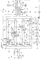
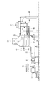
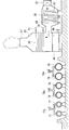
- FIG. 1 is a schematic configuration diagram illustrating a combined power plant according to an embodiment of the present invention. It is a side view which shows the 1st waste heat recovery boiler of FIG. It is a side view which shows the 5th waste heat recovery boiler and condenser of FIG.
- the combined power plant 1 includes a gas turbine power generation unit 10 that generates power using the driving force of a gas turbine (heat engine) 11, and exhaust fuel gas (hereinafter referred to as “exhaust gas”) discharged from the gas turbine 11.
- the steam turbine power generation unit 20 that generates power by recovering the heat of.
- the gas turbine power generation unit 10 includes one gas turbine 11 that is driven by fuel gas, and a generator 12 that generates power by the driving force of the gas turbine 11.
- the gas turbine 11 rotates the turbine (not shown) by burning the fuel gas supplied from the fuel gas supply line 15 using the atmosphere (air) supplied via the atmosphere supply line 14. Further, the gas turbine 11 is provided with an intake air cooler 16 (see FIG. 2) as necessary, and cools the air supplied through the air supply line 14.
- the generator 12 is connected to a turbine provided in the gas turbine 11 by a rotating shaft 13, and generates power by the rotational driving force of the turbine.
- the steam turbine power generation unit 20 generates power by using a plurality of exhaust heat recovery boilers to which exhaust gas discharged from the gas turbine 11 is supplied, a plurality of steam turbines driven by steam from the exhaust heat recovery boiler, and a driving force of the steam turbine. And a generator 21.
- the steam turbine power generation unit 20 supplies steam (or water supply) to the exhaust gas duct 22 for circulating the exhaust gas discharged from the gas turbine 11, the condenser 23 for condensing moisture in the exhaust gas, and various devices.
- Steam piping (or water supply piping) is provided.
- the exhaust gas duct 22 is a duct-like member, and the exhaust gas circulates inside. Further, the exhaust gas duct 22 has an upstream end connected to the exhaust gas outlet of the gas turbine 11 and a downstream end connected to a condenser 23. That is, the exhaust gas duct 22 guides the exhaust gas discharged from the gas turbine 11 to the condenser 23.
- the exhaust gas duct 22 branches into four at an intermediate position. In detail, it branches into the 1st exhaust gas duct 22a, the 2nd exhaust gas duct 22b, the 3rd exhaust gas duct 22c, and the 4th exhaust gas duct 22d. The branched first to fourth exhaust gas ducts 22d merge at the downstream end.
- five exhaust heat recovery boilers are provided. Specifically, in the exhaust gas flow discharged from the gas turbine 11, a first exhaust heat recovery boiler (first boiler) 24, a second exhaust heat recovery boiler (second boiler) 25, and a third exhaust heat arranged in parallel. A recovery boiler (third boiler) 26, a fourth exhaust heat recovery boiler (fourth boiler) 27, and a fifth exhaust gas disposed downstream of the first exhaust heat recovery boiler 24 to the fourth exhaust heat recovery boiler 27 in the exhaust gas flow. An exhaust heat recovery boiler (low temperature boiler) 28 is provided.
- the first exhaust heat recovery boiler 24 to the fifth exhaust heat recovery boiler 28 each have an outer shell constituted by a casing.
- the casing constituting the outer shell of each exhaust heat recovery boiler is a separate body. That is, the first exhaust heat recovery boiler 24 to the fifth exhaust heat recovery boiler 28 are individually provided, and each form an isolated space inside the casing.
- the first exhaust heat recovery boiler 24 is provided in the middle of the first exhaust gas duct 22a, and exhaust gas flowing through the first exhaust gas duct 22a is introduced and exhaust gas is exhausted to the first exhaust gas duct 22a. .
- the first exhaust heat recovery boiler 24 is provided with a flue through which exhaust gas flows, and an ultrahigh pressure superheater (first heat exchanger) 31 and a first ultrahigh pressure heat exchanger 32 are disposed in the flue.
- the ultra-high pressure superheater 31 is disposed on the upstream side of the exhaust gas flow
- the first ultra-high pressure heat exchanger 32 is disposed on the downstream side of the exhaust gas flow with respect to the ultra-high pressure superheater 31.
- Each of the ultra-high pressure superheater 31 and the first ultra-high pressure heat exchanger 32 has a heat transfer tube, and performs heat exchange between the steam flowing through the heat transfer tube and the exhaust gas flowing outside the heat transfer tube. It is a vessel.
- the first exhaust gas duct 22 a is provided with a first auxiliary burner 33 that heats the exhaust gas led to the first exhaust heat recovery boiler 24 on the exhaust gas inlet side of the first exhaust heat recovery boiler 24.
- the first auxiliary burner 33 injects the fuel gas supplied from the fuel gas supply system 30 into a part of the exhaust gas flowing through the first exhaust gas duct 22a, and ignites the input fuel gas to form a flame. Thus, the exhaust gas is heated.
- the second exhaust heat recovery boiler 25 is provided in the middle of the second exhaust gas duct 22b, and exhaust gas flowing through the second exhaust gas duct 22b is introduced and exhaust gas is exhausted to the second exhaust gas duct 22b. .
- the second exhaust heat recovery boiler 25 is provided with a flue through which exhaust gas flows, and a high pressure reheater (second heat exchanger) 34 and a second ultrahigh pressure heat exchanger 35 are arranged in the flue.
- the high pressure reheater 34 is disposed on the upstream side of the exhaust gas flow
- the second ultrahigh pressure heat exchanger 35 is disposed on the downstream side of the exhaust gas flow with respect to the high pressure reheater 34.
- the high-pressure reheater 34 and the second ultrahigh-pressure heat exchanger 35 each have a heat transfer tube, and perform heat exchange that exchanges heat between the steam that flows through the heat transfer tube and the exhaust gas that flows outside the heat transfer tube. It is a vessel.
- the second exhaust gas duct 22b is provided with a second auxiliary burner 36 for heating the exhaust gas led to the second exhaust heat recovery boiler 25 on the exhaust gas inlet side of the second exhaust heat recovery boiler 25.
- the second auxiliary burner 36 inputs the fuel gas supplied from the fuel gas supply system 30 into a part of the exhaust gas flowing through the second exhaust gas duct 22b, and ignites the input fuel gas to form a flame. Thus, the exhaust gas is heated.
- the third exhaust heat recovery boiler 26 is provided in the middle of the third exhaust gas duct 22c, and exhaust gas flowing through the third exhaust gas duct 22c is introduced and exhaust gas is exhausted to the third exhaust gas duct 22c. .
- the third exhaust heat recovery boiler 26 is provided with a flue through which exhaust gas flows, and an intermediate pressure reheater (third heat exchanger) 37 and a third ultrahigh pressure heat exchanger 38 are provided in the flue. Has been placed.
- the intermediate pressure reheater 37 is disposed on the upstream side of the exhaust gas flow, and the third ultrahigh pressure heat exchanger 38 is disposed on the downstream side of the exhaust gas flow with respect to the intermediate pressure reheater 37.
- Each of the intermediate-pressure reheater 37 and the third ultrahigh-pressure heat exchanger 38 has a heat transfer tube, and performs heat exchange between steam flowing through the heat transfer tube and exhaust gas flowing outside the heat transfer tube. It is an exchanger.
- the third exhaust gas duct 22c is provided with a third auxiliary burner 39 for heating the exhaust gas led to the third exhaust heat recovery boiler 26 on the exhaust gas inlet side of the third exhaust heat recovery boiler 26.
- the third auxiliary burner 39 inputs the fuel gas supplied from the fuel gas supply system 30 into a part of the exhaust gas flowing through the third exhaust gas duct 22c, and ignites the input fuel gas to form a flame. Thus, the exhaust gas is heated.
- the fourth exhaust heat recovery boiler 27 is provided in the middle of the fourth exhaust gas duct 22d, and exhaust gas flowing through the fourth exhaust gas duct 22d is introduced and exhaust gas is exhausted to the fourth exhaust gas duct 22d. .
- the fourth exhaust heat recovery boiler 27 is provided with a flue through which exhaust gas flows, and a low-pressure reheater (fourth heat exchanger) 40 and a fourth ultra-high pressure heat exchanger 41 are arranged in the flue.
- the low pressure reheater 40 is disposed on the upstream side of the exhaust gas flow
- the fourth ultrahigh pressure heat exchanger 41 is disposed on the downstream side of the exhaust gas flow with respect to the low pressure reheater 40.
- the low-pressure reheater 40 and the fourth ultrahigh-pressure heat exchanger 41 each have a heat transfer tube, and perform heat exchange that exchanges heat between the steam flowing through the heat transfer tube and the exhaust gas flowing outside the heat transfer tube. It is a vessel.
- the fourth exhaust gas duct 22 d is provided with a fourth auxiliary burner 42 that heats the exhaust gas led to the fourth exhaust heat recovery boiler 27 on the exhaust gas inlet side of the fourth exhaust heat recovery boiler 27.
- the fourth auxiliary burner 42 injects the fuel gas supplied from the fuel gas supply system 30 into a part of the exhaust gas flowing through the fourth exhaust gas duct 22d, and ignites the input fuel gas to form a flame. Thus, the exhaust gas is heated.
- the fifth exhaust heat recovery boiler 28 is provided in the exhaust gas duct 22 on the downstream side in the exhaust gas flow from the confluence of the first exhaust gas duct 22a to the fourth exhaust gas duct 22d, and the exhaust gas flowing through the exhaust gas duct 22 is introduced. In addition, exhaust gas is discharged to the exhaust gas duct 22.
- the fifth exhaust heat recovery boiler 28 is provided with a flue through which exhaust gas flows, and in this flue, a first economizer (low temperature heat exchanger) 43 and a second economizer (low temperature heat exchanger). ) 44 is arranged.
- the first economizer 43 is disposed on the upstream side of the exhaust gas flow
- the second economizer 44 is disposed on the downstream side of the exhaust gas flow with respect to the first economizer 43.
- Each of the first economizer 43 and the second economizer 44 has a heat transfer tube, and performs heat exchange between steam and / or feed water flowing through the heat transfer tube and exhaust gas flowing outside the heat transfer tube. It is a heat exchanger to perform.
- the first auxiliary burner 33 to the fourth auxiliary burner 42 are controlled to start and stop by a control device (not shown). Moreover, it is controlled by the control device so as to form a flame so as to achieve a desired exhaust gas temperature. In the present embodiment, the first auxiliary burner 33 to the fourth auxiliary burner 42 are respectively set so that the temperature of the steam discharged from the first exhaust heat recovery boiler 24 to the fourth exhaust heat recovery boiler 27 becomes the planned temperature. It is controlled by the control device.
- the control device includes, for example, a CPU (Central Processing Unit), a RAM (Random Access Memory), a ROM (Read Only Memory), and a computer-readable storage medium.
- a series of processes for realizing various functions is stored in a storage medium or the like in the form of a program as an example, and the CPU reads the program into a RAM or the like to execute information processing / arithmetic processing.
- the program is preinstalled in a ROM or other storage medium, provided in a state stored in a computer-readable storage medium, or distributed via wired or wireless communication means. Etc. may be applied.
- the computer-readable storage medium is a magnetic disk, a magneto-optical disk, a CD-ROM, a DVD-ROM, a semiconductor memory, or the like.
- the condenser 23 is connected to the downstream end of the exhaust gas duct 22, and the exhaust gas flowing through the exhaust gas duct 22 is introduced into the condenser 23.
- the condenser 23 is provided with a flue through which exhaust gas flows, and a preheater 45 is disposed in the flue.
- the preheater 45 has a heat transfer tube, and is a heat exchanger that performs heat exchange between water supplied through the heat transfer tube and exhaust gas flowing through the outside of the heat transfer tube.
- the condenser 23 performs heat exchange between the exhaust gas and the feed water, thereby cooling the exhaust gas and condensing moisture in the exhaust gas.
- a condensed water storage section 46 is provided at the lower part of the condenser 23 and stores condensed condensed water.
- a chimney 47 for releasing the exhaust gas after heat exchange to the atmosphere is provided at the upper part of the condenser 23.
- a condensed water pipe 48 that discharges condensed water from the condenser 23 is connected to the condensed water storage unit 46.
- the downstream end of the condensed water pipe 48 is connected to an intake air cooler 16 provided in the gas turbine 11, and is used for cooling air supplied to the gas turbine 11.
- first steam turbine first steam turbine
- second steam turbine high pressure steam turbine
- third steam turbine third steam turbine
- fourth steam turbine fourth steam turbine
- the generator 21 is connected to the rotating shaft 55, and the generator 21 generates power by the rotational driving force of each steam turbine.
- Each steam turbine is provided on a turbine mount 56 (see FIG. 2) standing on the ground.
- each steam turbine is arranged adjacent to an exhaust heat recovery boiler that is a steam supply source.
- the ultra high pressure steam turbine 51 is disposed adjacent to the first exhaust heat recovery boiler 24.
- the outlet of the heat transfer tube of the super high pressure superheater 31 and the inlet of the super high pressure steam turbine 51 are arranged close to each other.
- the high-pressure steam turbine 52 is disposed adjacent to the second exhaust heat recovery boiler 25.
- the outlet of the heat transfer tube of the high pressure reheater 34 and the inlet of the high pressure steam turbine 52 are arranged close to each other.
- the intermediate pressure steam turbine 53 is disposed adjacent to the third exhaust heat recovery boiler 26.
- the outlet of the heat transfer tube of the intermediate pressure reheater 37 and the inlet of the intermediate pressure steam turbine 53 are arranged close to each other.
- the low pressure steam turbine 54 is disposed adjacent to the fourth exhaust heat recovery boiler 27. Specifically, the outlet of the heat transfer tube of the low-pressure reheater 40 and the inlet of the low-pressure steam turbine 54 are arranged close to each other.
- Each steam pipe and each water supply pipe have a material, a thickness of the pipe (distance between the inner peripheral surface and the outer peripheral surface), etc., according to the temperature and pressure of the steam or water supplied through the interior.
- the outlet of the heat transfer tube provided in the preheater 45 and the inlet of the heat transfer tube provided in the second economizer 44 are connected by a first water supply pipe 61. Inside the first water supply pipe 61, water supply is circulated. The outlet of the heat transfer tube provided in the second economizer 44 and the inlet of the heat transfer tube provided in the first economizer 43 are connected by a second water supply pipe 62. Inside the second water supply pipe 62, water supply is circulated. Moreover, the 2nd water supply piping 62 is provided with the ultra high pressure water supply pump 60, pressurizes the water supply which distribute
- the first super high pressure steam pipe 63 is connected to the outlet of the heat transfer pipe provided in the first economizer 43.
- the first ultra-high pressure steam pipe 63 branches at an intermediate position, and the downstream end is connected to four heat exchangers. Specifically, the four downstream ends of the first ultrahigh pressure steam pipe 63 are the inlet of the heat transfer tube of the first ultrahigh pressure heat exchanger 32, the inlet of the heat transfer tube of the second ultrahigh pressure heat exchanger 35, and the third ultrahigh pressure.
- the inlet of the heat exchanger tube of the heat exchanger 38 and the inlet of the heat exchanger tube of the fourth ultra high pressure heat exchanger 41 are connected to each other.
- the upstream ends of the second ultra-high pressure steam pipes 64 are connected to the outlets of the heat transfer tubes.
- the second ultra-high pressure steam pipes 64 connected to the respective outlets join at intermediate positions.
- the downstream end of the joined second super high pressure steam pipe 64 is connected to the inlet of the heat transfer pipe of the super high pressure superheater 31.
- the inlet of the heat transfer tube of the ultrahigh pressure superheater 31 and the inlet of the ultrahigh pressure steam turbine 51 are connected by a third ultrahigh pressure steam pipe (first steam pipe) 65.
- a third ultrahigh pressure steam pipe 65 Inside the third ultrahigh-pressure steam pipe 65, high-temperature steam (temperature of about 600 ° C. or higher) heated by the ultrahigh-pressure superheater 31 flows. For this reason, the 3rd super high pressure steam piping 65 is formed with the material excellent in heat resistance.
- steam in an ultra-high pressure state (about 30 MPa or higher pressure) flows through the third ultra-high pressure steam pipe 65. For this reason, the thickness (distance between the inner peripheral surface and the outer peripheral surface) of the third ultra-high pressure steam pipe 65 is formed to be thick enough to withstand the ultra-high pressure.
- the outlet of the ultrahigh pressure steam turbine 51 and the inlet of the heat transfer pipe of the high pressure reheater 34 are connected by a first high pressure steam pipe 66.
- the outlet of the heat transfer tube of the high pressure reheater 34 and the inlet of the high pressure steam turbine 52 are connected by a second high pressure steam pipe (second steam pipe) 67.
- High-pressure steam circulates inside the first high-pressure steam pipe 66 and the second high-pressure steam pipe 67. Inside the second high-pressure steam pipe 67, high-temperature (about 600 ° C. or higher) steam heated by the high-pressure reheater 34 flows. For this reason, the second high-pressure steam pipe 67 is formed of a material having excellent heat resistance.
- the outlet of the high pressure steam turbine 52 and the inlet of the heat transfer pipe of the intermediate pressure reheater 37 are connected by a first intermediate pressure steam pipe 68.
- the outlet of the heat transfer tube of the intermediate pressure reheater 37 and the inlet of the intermediate pressure steam turbine 53 are connected by a second intermediate pressure steam pipe (third steam pipe) 69.
- first intermediate pressure steam pipe 68 and the second intermediate pressure steam pipe 69 medium pressure steam flows.
- second intermediate pressure steam pipe 69 high-temperature (about 600 ° C. or higher) steam heated by the intermediate pressure reheater 37 circulates. For this reason, the second intermediate pressure steam pipe 69 is formed of a material having excellent heat resistance.
- the outlet of the intermediate pressure steam turbine 53 and the inlet of the heat transfer pipe of the low pressure reheater 40 are connected by a first low pressure steam pipe 70.
- the outlet of the heat transfer tube of the low-pressure reheater 40 and the inlet of the low-pressure steam turbine 54 are connected by a second low-pressure steam pipe (fourth steam pipe) 71.
- Low-pressure steam circulates inside the first low-pressure steam pipe 70 and the second low-pressure steam pipe 71. Inside the second low-pressure steam pipe 71, high-temperature steam (temperature of about 600 ° C. or higher) heated by the low-pressure reheater 40 flows. For this reason, the second low-pressure steam pipe 71 is formed of a material having excellent heat resistance.
- the upstream end of the third low-pressure steam pipe 72 is connected to the outlet of the low-pressure steam turbine 54.
- the downstream end of the third low-pressure steam pipe 72 is connected to the inlet of the condenser 73.
- the introduced steam is condensed to generate feed water.
- the outlet of the condenser 73 and the inlet of the heat transfer pipe of the preheater 45 are connected by a third water supply pipe 74.
- the third feed water pipe 74 is provided with a condensate pump 75 that boosts the feed water flowing through the third feed water pipe 74 and guides it to the condenser 23.
- the combined power plant 1 is provided with a heat storage drum for storing steam, as shown in FIG.
- the heat storage drum stores steam therein.
- the combined power plant 1 of this embodiment includes a high-pressure heat storage drum 77, an intermediate-pressure heat storage drum 78, and a low-pressure heat storage drum 79 as heat storage drums.
- the high-pressure heat storage drum 77 is connected to the high-pressure steam turbine 52 by a pipe 77 a and supplies, for example, steam stored therein to the high-pressure steam turbine 52 when the high-pressure steam turbine 52 is rapidly started.
- the intermediate pressure heat storage drum 78 is connected to the intermediate pressure steam turbine 53 by a pipe 78 a, and for example, steam stored in the medium pressure steam turbine 53 at the time of rapid start of the intermediate pressure steam turbine 53 is supplied to the intermediate pressure steam turbine 53. Supply.
- the low-pressure heat storage drum 79 is connected to the low-pressure steam turbine 54 by a pipe 79a, and supplies the steam stored therein to the low-pressure steam turbine 54, for example, when the low-pressure steam turbine 54 is rapidly started.
- the exhaust gas discharged from the gas turbine 11 flows through the exhaust gas duct 22 and flows into the first exhaust gas duct 22a to the fourth exhaust gas duct 22d at the branch position.
- the exhaust gas flowing into the first exhaust gas duct 22a flows through the first exhaust gas duct 22a and is heated to a predetermined temperature by the first auxiliary burner 33.
- the exhaust gas heated by the auxiliary combustion burner is introduced into the first exhaust heat recovery boiler 24 and flows through the flue formed in the first exhaust heat recovery boiler 24.
- Exhaust gas flowing in the flue is cooled by exchanging heat with steam in the ultrahigh pressure superheater 31 and the ultrahigh pressure heat exchanger provided in the flue.
- the cooled exhaust gas is discharged from the first exhaust heat recovery boiler 24 into the first exhaust gas duct 22a.
- emitted in the 1st exhaust gas duct 22a distribute
- Exhaust gas flowing into the other exhaust gas ducts (second exhaust gas duct 22b to fourth exhaust gas duct 22d) is also heated to a predetermined temperature by the auxiliary burner provided in each exhaust gas duct, as is the exhaust gas flowing into the first exhaust gas duct 22a. It is heated and introduced into the exhaust heat recovery boiler, and heat is exchanged with steam in the reheater and heat exchanger provided in each exhaust heat recovery boiler, and then cooled. And it is discharged
- the combined exhaust gas is introduced into the fifth exhaust heat recovery boiler 28.
- the exhaust gas introduced into the fifth exhaust heat recovery boiler 28 flows through the flue formed in the fifth exhaust heat recovery boiler 28.
- the exhaust gas flowing in the flue is cooled by exchanging heat with steam and / or feed water in the first economizer 43 and the second economizer 44 provided in the flue.
- the cooled exhaust gas is discharged from the fifth exhaust heat recovery boiler 28 and introduced into the condenser 23 through the exhaust gas duct 22.
- the exhaust gas is cooled by performing heat exchange with the feed water in the preheater 45. At this time, the moisture contained in the exhaust gas is condensed by being cooled and falls to the condensed water reservoir 46 as condensed water. On the other hand, the exhaust gas subjected to heat exchange is discharged from the fifth exhaust heat recovery boiler 28 and discharged to the atmosphere via the chimney 47.
- the generated water supply flows through the third water supply pipe 74, is pressurized by the condensate pump 75, and is introduced into the condenser 23.
- the feed water introduced into the condenser 23 circulates through the heat transfer tubes constituting the preheater 45 and is heated by exchanging heat with the exhaust gas.
- the feed water heated by the condenser 23 is discharged from the preheater 45, flows through the first feed water pipe 61, and is introduced into the second economizer 44 provided in the fifth exhaust heat recovery boiler 28.
- the feed water introduced into the second economizer 44 flows through the heat transfer tubes constituting the second economizer 44 and is heated by exchanging heat with the exhaust gas.
- the heated feed water is discharged from the second economizer 44, circulates through the second feed water pipe 62, and is boosted by the ultra high pressure feed pump 60 provided in the second feed water pipe 62 to be in an ultra high pressure state.
- the feed water boosted by the ultrahigh pressure feed pump 60 is introduced into the first economizer 43, circulates through the heat transfer pipes constituting the first economizer 43, exchanges heat with exhaust gas, is heated, It becomes.
- the steam heated by the fifth exhaust heat recovery boiler 28 is discharged from the first economizer 43, and passes through the first super high pressure steam pipe 63 to the first exhaust heat recovery boiler 24 to the fourth exhaust heat recovery boiler 27.
- the steam introduced into each ultra-high pressure heat exchangers flows through the heat transfer tubes constituting each ultra-high pressure heat exchanger and is superheated by exchanging heat with the exhaust gas to become superheated steam.
- the generated superheated steam is discharged from each ultra-high pressure heat exchanger, merges, and circulates in the second ultra-high pressure steam pipe 64.
- the steam that has flowed through the second ultrahigh pressure steam pipe 64 is introduced into the ultrahigh pressure superheater 31 provided in the first exhaust heat recovery boiler 24.
- the steam introduced into the super high pressure superheater 31 is further superheated by the exhaust gas flowing through the first exhaust heat recovery boiler 24 and discharged to the third super high pressure steam pipe 65.
- the steam discharged to the third ultra high pressure steam pipe 65 circulates in the pipe and is introduced into the ultra high pressure steam turbine 51.
- the introduced steam rotates a turbine (not shown) provided in the ultrahigh pressure steam turbine 51.
- the steam that has rotated the turbine expands to a high pressure state and is discharged from the ultrahigh pressure steam turbine 51.
- the discharged steam is introduced into the high pressure reheater 34 provided in the second exhaust heat recovery boiler 25 via the first high pressure steam pipe 66.
- the steam introduced into the high-pressure reheater 34 is heated again by exchanging heat with the exhaust gas flowing through the second exhaust heat recovery boiler 25 and is discharged to the second high-pressure steam pipe 67.
- the steam discharged to the second high-pressure steam pipe 67 circulates in the pipe and is introduced into the high-pressure steam turbine 52.
- the introduced steam rotates a turbine (not shown) provided in the high-pressure steam turbine 52.
- the steam that rotates the turbine expands to an intermediate pressure state and is discharged from the high-pressure steam turbine 52.
- the discharged steam is introduced into the intermediate pressure reheater 37 provided in the third exhaust heat recovery boiler 26 via the first intermediate pressure steam pipe 68.
- the steam introduced into the intermediate pressure reheater 37 is heated again by exchanging heat with the exhaust gas flowing through the third exhaust heat recovery boiler 26 and discharged to the second intermediate pressure steam pipe 69.
- the steam discharged to the second intermediate pressure steam pipe 69 circulates in the pipe and is introduced into the intermediate pressure steam turbine 53.
- the introduced steam rotates a turbine (not shown) provided in the intermediate pressure steam turbine 53.
- the steam that has rotated the turbine expands to a low pressure state and is discharged from the intermediate pressure steam turbine 53.
- the discharged steam is introduced into the low pressure reheater 40 provided in the fourth exhaust heat recovery boiler 27 via the first low pressure steam pipe 70.
- the steam introduced into the low-pressure reheater 40 is heated again by exchanging heat with the exhaust gas flowing through the fourth exhaust heat recovery boiler 27 and is discharged to the second low-pressure steam pipe 71.
- the steam discharged to the second low-pressure steam pipe 71 flows through the pipe and is introduced into the low-pressure steam turbine 54.
- the introduced steam rotates a turbine (not shown) provided in the low-pressure steam turbine 54.
- the steam that has rotated the turbine is discharged from the low-pressure steam turbine 54 and introduced into the condenser 73.
- the condenser 73 generates feed water by condensing the introduced steam.
- the generated water supply flows through the third water supply pipe 74 and is introduced into the condenser 23 as described above. Steam and water supply in the combined power plant 1 according to the present embodiment circulate in this way.
- the fourth exhaust heat recovery boiler 27 having the low-pressure reheater 40 is constituted by another boiler. Accordingly, each exhaust heat recovery boiler is reduced in size as compared with the configuration in which the super high pressure superheater 31, the high pressure reheater 34, the intermediate pressure reheater 37, and the low pressure reheater 40 are provided in one exhaust heat recovery boiler. can do. Therefore, the exhaust heat recovery boiler constituting the combined power plant 1 can be easily installed. Moreover, since each exhaust heat recovery boiler can be reduced in size, the layout freedom in arrangement
- each waste heat recovery is carried out.
- the number of heat exchangers provided in the boiler is small. Thereby, the freedom degree on a layout can be improved about arrangement
- each exhaust heat recovery boiler is downsized and layout flexibility is improved so that each exhaust heat recovery boiler and each steam turbine to which steam is supplied are arranged adjacent to each other. I am letting.
- the pipes (the third ultra-high pressure steam pipe 65, the second high-pressure steam pipe 67, the second medium-pressure steam pipe 69, and the second pipe) that connect each of the exhaust heat recovery boilers and each steam turbine to which the steam is supplied.
- the low-pressure steam pipe 71) can be shortened.
- the length of expensive piping can be shortened, the cost can be significantly reduced.
- the third super high pressure steam pipe 65 is formed of a material having a high material unit price and an excellent heat resistance, and has a super high pressure. It is necessary to make the pipe thickness (distance between the inner peripheral surface and the outer peripheral surface of the pipe) that can withstand. For this reason, especially the 3rd super-high pressure steam pipe 65 has a high cost per unit length. In this embodiment, since the 1st exhaust heat recovery boiler 24 and the 1st steam turbine are arrange
- the first auxiliary burner 33 to the fourth auxiliary burner 42 are arranged on the inlet side of the first exhaust heat recovery boiler 24 to the fourth exhaust heat recovery boiler 27, respectively.
- each exhaust heat recovery boiler is provided with an auxiliary combustion burner for heating the exhaust gas, so that the temperature of the exhaust gas in each exhaust heat recovery boiler is adjusted to a temperature according to the state of each heat exchanger by each auxiliary combustion burner. Can be adjusted. Since the temperature of the exhaust gas can be adjusted, the steam can be heated to a desired temperature in each heat exchanger provided in the first exhaust heat recovery boiler 24 to the fourth exhaust heat recovery boiler 27. .
- each steam turbine (super high pressure steam turbine 51, high pressure steam turbine 52, medium pressure steam turbine 53). And steam at a temperature corresponding to the performance of each steam turbine can be supplied to the low-pressure steam turbine 54). Therefore, the driving efficiency of each steam turbine can be improved.
- the first exhaust heat recovery boiler 24 to the fourth exhaust heat recovery boiler 27 provided with auxiliary combustion burners are provided in parallel in the exhaust gas flow. Thereby, in each exhaust heat recovery boiler, the temperature of exhaust gas can be adjusted without being influenced by other exhaust heat recovery boilers. Therefore, since the exhaust gas temperature can be adjusted more precisely in each exhaust heat recovery boiler, steam at a temperature corresponding to each steam turbine can be supplied to each steam turbine more precisely.
- a reheater (a high pressure reheater 34, an intermediate pressure reheater 37, a low pressure reheater 40) is disposed downstream of the steam flow of the superheater (super high pressure superheater 31). ) Is provided, so-called three-stage reheat cycle is applied. In this way, a large amount of heat can be recovered from the exhaust gas of the gas turbine 11 by using a three-stage reheating cycle. Therefore, power generation efficiency can be improved.
- the three-stage reheat cycle is applied to improve the power generation efficiency, and the superheater and each reheater are individually provided with the exhaust heat recovery boiler. And the expensive piping which connects a reheater and a steam turbine can be shortened, and cost can be reduced.
- the first economizer 43 and the second economizer 44 are provided on the downstream side (low temperature portion of the exhaust gas temperature) in the exhaust gas flow to recover the heat of the exhaust gas. Therefore, compared with a configuration in which the first economizer 43 and the second economizer 44 are not provided, the energy efficiency of the combined power plant 1 as a whole can be improved.
- the condenser 23 is provided on the most downstream side (the lowest temperature portion of the exhaust gas temperature) in the exhaust gas flow. Thereby, the water
- the collected condensed water is guided to the intake air cooler 16 and used for intake air cooling of the gas turbine 11.
- the condensed water used for intake air cooling is contained in the exhaust gas discharged from the gas turbine 11, and after passing through the above-described exhaust gas flow, it is led to the condenser 23 and condensed again. In this way, the condensed water condensed in the condenser 23 can be circulated and used as cooling water for cooling the supply air of the gas turbine 11. Therefore, since it is not necessary to supply the cooling water for supplying the cooling water for cooling the intake air of the gas turbine 11 from the outside, the configuration can be simplified and the running cost can be reduced.
- a high-pressure heat storage drum 77 an intermediate-pressure heat storage drum 78, and a low-pressure heat storage drum 79 are provided.
- this invention is not limited to the invention concerning the said embodiment, In the range which does not deviate from the summary, it can change suitably.
- the present invention is not limited to this.
- gas exhausted from a heat engine other than the gas turbine may be introduced into the exhaust heat recovery boiler.
- gas discharged from the fuel cell may be introduced into the exhaust heat recovery boiler.
- the said embodiment demonstrated the example which applies the three-stage reheating cycle which provides three reheaters, this invention is not limited to this.
- the number of reheaters may be less than 3, or 4 or more. That is, the present invention can be applied to a single-stage reheat cycle or any number of multistage reheat cycles.
- the super high pressure superheater 31, the high pressure reheater 34, the intermediate pressure reheater 37, and the low pressure reheater 40 are all provided in individual exhaust heat recovery boilers. Is not limited to this. Any one of them may be provided in an individual exhaust heat recovery boiler. For example, only the super high pressure superheater 31 is provided in an individual exhaust heat recovery boiler, and three reheaters are provided in one exhaust heat recovery boiler. May be provided.
- the example in which the exhaust gas from one gas turbine 11 is branched and supplied to the first exhaust heat recovery boiler 24 to the fourth exhaust heat recovery boiler 27 has been described. It is not limited.
- two gas turbines may be provided, and the exhaust gas from the two gas turbines may be branched and supplied to each exhaust heat recovery boiler.
- four gas turbines may be provided to have a one-to-one correspondence with the first to fourth exhaust heat recovery boilers.
- shaft were demonstrated, in the case of one gas turbine, The gas turbine and each steam turbine may be provided coaxially.
- the superheater has a higher heat absorption rate than the reheater, but the first super high pressure heat exchanger 32 provided in the first exhaust heat recovery boiler 24 provided with the superheater is omitted, and the first exhaust is removed.
- the amount of heat absorption in each of the heat recovery boiler 24 to the fourth exhaust heat recovery boiler 27 may be the same. The design can be facilitated by setting the heat absorption amounts in the first exhaust heat recovery boiler 24 to the fourth exhaust heat recovery boiler 27 to be approximately the same.
Landscapes
- Engineering & Computer Science (AREA)
- Chemical & Material Sciences (AREA)
- Combustion & Propulsion (AREA)
- Mechanical Engineering (AREA)
- General Engineering & Computer Science (AREA)
- Life Sciences & Earth Sciences (AREA)
- Sustainable Development (AREA)
- Sustainable Energy (AREA)
- Physics & Mathematics (AREA)
- Thermal Sciences (AREA)
- Engine Equipment That Uses Special Cycles (AREA)
Applications Claiming Priority (2)
| Application Number | Priority Date | Filing Date | Title |
|---|---|---|---|
| JP2018077684A JP7143107B2 (ja) | 2018-04-13 | 2018-04-13 | 複合発電プラント |
| JP2018-077684 | 2018-04-13 |
Publications (1)
| Publication Number | Publication Date |
|---|---|
| WO2019198756A1 true WO2019198756A1 (ja) | 2019-10-17 |
Family
ID=68164176
Family Applications (1)
| Application Number | Title | Priority Date | Filing Date |
|---|---|---|---|
| PCT/JP2019/015618 Ceased WO2019198756A1 (ja) | 2018-04-13 | 2019-04-10 | 複合発電プラント |
Country Status (2)
| Country | Link |
|---|---|
| JP (1) | JP7143107B2 (cg-RX-API-DMAC7.html) |
| WO (1) | WO2019198756A1 (cg-RX-API-DMAC7.html) |
Cited By (1)
| Publication number | Priority date | Publication date | Assignee | Title |
|---|---|---|---|---|
| US11661867B2 (en) * | 2019-03-07 | 2023-05-30 | Mitsubishi Heavy Industries, Ltd. | Gas turbine exhaust heat recovery plant |
Citations (6)
| Publication number | Priority date | Publication date | Assignee | Title |
|---|---|---|---|---|
| JPS6036703A (ja) * | 1983-07-18 | 1985-02-25 | デイ.ビイ.エイ.パルガ,エス.エル | 蒸気タービンによつて駆動される船舶の推進プラント |
| JPH03151505A (ja) * | 1989-10-24 | 1991-06-27 | Asea Brown Boveri Ag | ガス/蒸気発電設備 |
| JP2001207808A (ja) * | 2000-01-21 | 2001-08-03 | Mitsubishi Heavy Ind Ltd | 蒸気冷却急速起動システム |
| JP2009085182A (ja) * | 2007-10-02 | 2009-04-23 | Hitachi Ltd | コンバインドサイクル発電プラント |
| JP2011220161A (ja) * | 2010-04-07 | 2011-11-04 | Toshiba Corp | 蒸気タービンプラント |
| JP2016003579A (ja) * | 2014-06-13 | 2016-01-12 | 三菱重工業株式会社 | コンバインドサイクル設備 |
Family Cites Families (1)
| Publication number | Priority date | Publication date | Assignee | Title |
|---|---|---|---|---|
| JP6390067B2 (ja) * | 2017-10-18 | 2018-09-19 | 三菱日立パワーシステムズ株式会社 | 排熱回収システム、これを備えているガスタービンプラント、及び排熱回収方法 |
-
2018
- 2018-04-13 JP JP2018077684A patent/JP7143107B2/ja active Active
-
2019
- 2019-04-10 WO PCT/JP2019/015618 patent/WO2019198756A1/ja not_active Ceased
Patent Citations (6)
| Publication number | Priority date | Publication date | Assignee | Title |
|---|---|---|---|---|
| JPS6036703A (ja) * | 1983-07-18 | 1985-02-25 | デイ.ビイ.エイ.パルガ,エス.エル | 蒸気タービンによつて駆動される船舶の推進プラント |
| JPH03151505A (ja) * | 1989-10-24 | 1991-06-27 | Asea Brown Boveri Ag | ガス/蒸気発電設備 |
| JP2001207808A (ja) * | 2000-01-21 | 2001-08-03 | Mitsubishi Heavy Ind Ltd | 蒸気冷却急速起動システム |
| JP2009085182A (ja) * | 2007-10-02 | 2009-04-23 | Hitachi Ltd | コンバインドサイクル発電プラント |
| JP2011220161A (ja) * | 2010-04-07 | 2011-11-04 | Toshiba Corp | 蒸気タービンプラント |
| JP2016003579A (ja) * | 2014-06-13 | 2016-01-12 | 三菱重工業株式会社 | コンバインドサイクル設備 |
Cited By (1)
| Publication number | Priority date | Publication date | Assignee | Title |
|---|---|---|---|---|
| US11661867B2 (en) * | 2019-03-07 | 2023-05-30 | Mitsubishi Heavy Industries, Ltd. | Gas turbine exhaust heat recovery plant |
Also Published As
| Publication number | Publication date |
|---|---|
| JP2019183777A (ja) | 2019-10-24 |
| JP7143107B2 (ja) | 2022-09-28 |
Similar Documents
| Publication | Publication Date | Title |
|---|---|---|
| US11274575B2 (en) | Gas turbine plant and operation method therefor | |
| US9903276B2 (en) | Preheating device for gas turbine fuel, gas turbine plant provided therewith, and preheating method for gas turbine fuel | |
| CN104279058B (zh) | 联合循环发电设备以及操作联合循环发电设备的方法 | |
| JP2009092372A (ja) | 超臨界蒸気複合サイクル及びその方法 | |
| US10900418B2 (en) | Fuel preheating system for a combustion turbine engine | |
| JP2007032568A (ja) | 複合サイクル発電プラント | |
| US9188028B2 (en) | Gas turbine system with reheat spray control | |
| MX2013007023A (es) | Un montaje de evaporador supercritico y recalentador generador de vapor con recuperacion de calor supercritico. | |
| US9003764B2 (en) | System and method for thermal control in a gas turbine engine | |
| RU2662257C2 (ru) | Интегрированная система утилизации тепла дымовых газов | |
| CN104420995A (zh) | 联合循环系统及其操作方法及对应的热回收蒸汽发生器 | |
| US20180003085A1 (en) | Steam turbine plant, combined cycle plant provided with same, and method of operating steam turbine plant | |
| US20160273406A1 (en) | Combined cycle system | |
| JP7143107B2 (ja) | 複合発電プラント | |
| JP2020143634A (ja) | ガスタービン排熱回収プラント | |
| JP7121185B2 (ja) | 天然ガス再ガス化を含む発電プラント | |
| JP6415122B2 (ja) | コンバインドサイクル設備 | |
| JP6188192B2 (ja) | ガスタービン用燃料の予熱装置、これを備えているガスタービンプラント、及びガスタービン用燃料の予熱方法 | |
| JP6057803B2 (ja) | ガスタービンプラント、及びガスタービンプラントの運転方法 | |
| WO2024038724A1 (ja) | コンバインドサイクル発電設備 | |
| RU2686541C1 (ru) | Парогазовая установка | |
| JP7414663B2 (ja) | 排熱回収ボイラ | |
| JP6132616B2 (ja) | ガスタービンプラント、及びガスタービンプラントの運転方法 | |
| JP6101604B2 (ja) | 蒸気タービンプラント、これを備えているコンバインドサイクルプラント、及び蒸気タービンプラントの運転方法 | |
| JP7036622B2 (ja) | 既設ボイラ活用高蒸気条件ボイラプラント |
Legal Events
| Date | Code | Title | Description |
|---|---|---|---|
| 121 | Ep: the epo has been informed by wipo that ep was designated in this application |
Ref document number: 19785401 Country of ref document: EP Kind code of ref document: A1 |
|
| NENP | Non-entry into the national phase |
Ref country code: DE |
|
| 122 | Ep: pct application non-entry in european phase |
Ref document number: 19785401 Country of ref document: EP Kind code of ref document: A1 |