WO2019198599A1 - 車両の制御システム - Google Patents
車両の制御システム Download PDFInfo
- Publication number
- WO2019198599A1 WO2019198599A1 PCT/JP2019/014840 JP2019014840W WO2019198599A1 WO 2019198599 A1 WO2019198599 A1 WO 2019198599A1 JP 2019014840 W JP2019014840 W JP 2019014840W WO 2019198599 A1 WO2019198599 A1 WO 2019198599A1
- Authority
- WO
- WIPO (PCT)
- Prior art keywords
- drive source
- engine
- vehicle
- communication
- state
- Prior art date
- Legal status (The legal status is an assumption and is not a legal conclusion. Google has not performed a legal analysis and makes no representation as to the accuracy of the status listed.)
- Ceased
Links
Images




Classifications
-
- G—PHYSICS
- G07—CHECKING-DEVICES
- G07C—TIME OR ATTENDANCE REGISTERS; REGISTERING OR INDICATING THE WORKING OF MACHINES; GENERATING RANDOM NUMBERS; VOTING OR LOTTERY APPARATUS; ARRANGEMENTS, SYSTEMS OR APPARATUS FOR CHECKING NOT PROVIDED FOR ELSEWHERE
- G07C9/00—Individual registration on entry or exit
- G07C9/00174—Electronically operated locks; Circuits therefor; Nonmechanical keys therefor, e.g. passive or active electrical keys or other data carriers without mechanical keys
- G07C9/00309—Electronically operated locks; Circuits therefor; Nonmechanical keys therefor, e.g. passive or active electrical keys or other data carriers without mechanical keys operated with bidirectional data transmission between data carrier and locks
-
- B—PERFORMING OPERATIONS; TRANSPORTING
- B60—VEHICLES IN GENERAL
- B60R—VEHICLES, VEHICLE FITTINGS, OR VEHICLE PARTS, NOT OTHERWISE PROVIDED FOR
- B60R25/00—Fittings or systems for preventing or indicating unauthorised use or theft of vehicles
- B60R25/01—Fittings or systems for preventing or indicating unauthorised use or theft of vehicles operating on vehicle systems or fittings, e.g. on doors, seats or windscreens
- B60R25/04—Fittings or systems for preventing or indicating unauthorised use or theft of vehicles operating on vehicle systems or fittings, e.g. on doors, seats or windscreens operating on the propulsion system, e.g. engine or drive motor
-
- B—PERFORMING OPERATIONS; TRANSPORTING
- B60—VEHICLES IN GENERAL
- B60R—VEHICLES, VEHICLE FITTINGS, OR VEHICLE PARTS, NOT OTHERWISE PROVIDED FOR
- B60R25/00—Fittings or systems for preventing or indicating unauthorised use or theft of vehicles
- B60R25/20—Means to switch the anti-theft system on or off
- B60R25/24—Means to switch the anti-theft system on or off using electronic identifiers containing a code not memorised by the user
-
- B—PERFORMING OPERATIONS; TRANSPORTING
- B60—VEHICLES IN GENERAL
- B60W—CONJOINT CONTROL OF VEHICLE SUB-UNITS OF DIFFERENT TYPE OR DIFFERENT FUNCTION; CONTROL SYSTEMS SPECIALLY ADAPTED FOR HYBRID VEHICLES; ROAD VEHICLE DRIVE CONTROL SYSTEMS FOR PURPOSES NOT RELATED TO THE CONTROL OF A PARTICULAR SUB-UNIT
- B60W50/00—Details of control systems for road vehicle drive control not related to the control of a particular sub-unit, e.g. process diagnostic or vehicle driver interfaces
- B60W50/08—Interaction between the driver and the control system
- B60W50/12—Limiting control by the driver depending on vehicle state, e.g. interlocking means for the control input for preventing unsafe operation
-
- B—PERFORMING OPERATIONS; TRANSPORTING
- B62—LAND VEHICLES FOR TRAVELLING OTHERWISE THAN ON RAILS
- B62H—CYCLE STANDS; SUPPORTS OR HOLDERS FOR PARKING OR STORING CYCLES; APPLIANCES PREVENTING OR INDICATING UNAUTHORIZED USE OR THEFT OF CYCLES; LOCKS INTEGRAL WITH CYCLES; DEVICES FOR LEARNING TO RIDE CYCLES
- B62H5/00—Appliances preventing or indicating unauthorised use or theft of cycles; Locks integral with cycles
- B62H5/08—Appliances preventing or indicating unauthorised use or theft of cycles; Locks integral with cycles preventing the drive
-
- E—FIXED CONSTRUCTIONS
- E05—LOCKS; KEYS; WINDOW OR DOOR FITTINGS; SAFES
- E05B—LOCKS; ACCESSORIES THEREFOR; HANDCUFFS
- E05B49/00—Electric permutation locks; Circuits therefor ; Mechanical aspects of electronic locks; Mechanical keys therefor
-
- E—FIXED CONSTRUCTIONS
- E05—LOCKS; KEYS; WINDOW OR DOOR FITTINGS; SAFES
- E05B—LOCKS; ACCESSORIES THEREFOR; HANDCUFFS
- E05B83/00—Vehicle locks specially adapted for particular types of wing or vehicle
-
- F—MECHANICAL ENGINEERING; LIGHTING; HEATING; WEAPONS; BLASTING
- F02—COMBUSTION ENGINES; HOT-GAS OR COMBUSTION-PRODUCT ENGINE PLANTS
- F02D—CONTROLLING COMBUSTION ENGINES
- F02D29/00—Controlling engines, such controlling being peculiar to the devices driven thereby, the devices being other than parts or accessories essential to engine operation, e.g. controlling of engines by signals external thereto
- F02D29/02—Controlling engines, such controlling being peculiar to the devices driven thereby, the devices being other than parts or accessories essential to engine operation, e.g. controlling of engines by signals external thereto peculiar to engines driving vehicles; peculiar to engines driving variable pitch propellers
-
- F—MECHANICAL ENGINEERING; LIGHTING; HEATING; WEAPONS; BLASTING
- F02—COMBUSTION ENGINES; HOT-GAS OR COMBUSTION-PRODUCT ENGINE PLANTS
- F02D—CONTROLLING COMBUSTION ENGINES
- F02D45/00—Electrical control not provided for in groups F02D41/00 - F02D43/00
-
- G—PHYSICS
- G07—CHECKING-DEVICES
- G07C—TIME OR ATTENDANCE REGISTERS; REGISTERING OR INDICATING THE WORKING OF MACHINES; GENERATING RANDOM NUMBERS; VOTING OR LOTTERY APPARATUS; ARRANGEMENTS, SYSTEMS OR APPARATUS FOR CHECKING NOT PROVIDED FOR ELSEWHERE
- G07C9/00—Individual registration on entry or exit
- G07C9/00174—Electronically operated locks; Circuits therefor; Nonmechanical keys therefor, e.g. passive or active electrical keys or other data carriers without mechanical keys
- G07C9/00309—Electronically operated locks; Circuits therefor; Nonmechanical keys therefor, e.g. passive or active electrical keys or other data carriers without mechanical keys operated with bidirectional data transmission between data carrier and locks
- G07C2009/00317—Electronically operated locks; Circuits therefor; Nonmechanical keys therefor, e.g. passive or active electrical keys or other data carriers without mechanical keys operated with bidirectional data transmission between data carrier and locks keyless data carrier having only one limited data transmission range
-
- G—PHYSICS
- G07—CHECKING-DEVICES
- G07C—TIME OR ATTENDANCE REGISTERS; REGISTERING OR INDICATING THE WORKING OF MACHINES; GENERATING RANDOM NUMBERS; VOTING OR LOTTERY APPARATUS; ARRANGEMENTS, SYSTEMS OR APPARATUS FOR CHECKING NOT PROVIDED FOR ELSEWHERE
- G07C9/00—Individual registration on entry or exit
- G07C9/00174—Electronically operated locks; Circuits therefor; Nonmechanical keys therefor, e.g. passive or active electrical keys or other data carriers without mechanical keys
- G07C9/00309—Electronically operated locks; Circuits therefor; Nonmechanical keys therefor, e.g. passive or active electrical keys or other data carriers without mechanical keys operated with bidirectional data transmission between data carrier and locks
- G07C2009/00507—Electronically operated locks; Circuits therefor; Nonmechanical keys therefor, e.g. passive or active electrical keys or other data carriers without mechanical keys operated with bidirectional data transmission between data carrier and locks keyless data carrier having more than one function
-
- G—PHYSICS
- G07—CHECKING-DEVICES
- G07C—TIME OR ATTENDANCE REGISTERS; REGISTERING OR INDICATING THE WORKING OF MACHINES; GENERATING RANDOM NUMBERS; VOTING OR LOTTERY APPARATUS; ARRANGEMENTS, SYSTEMS OR APPARATUS FOR CHECKING NOT PROVIDED FOR ELSEWHERE
- G07C9/00—Individual registration on entry or exit
- G07C9/00174—Electronically operated locks; Circuits therefor; Nonmechanical keys therefor, e.g. passive or active electrical keys or other data carriers without mechanical keys
- G07C9/00309—Electronically operated locks; Circuits therefor; Nonmechanical keys therefor, e.g. passive or active electrical keys or other data carriers without mechanical keys operated with bidirectional data transmission between data carrier and locks
- G07C2009/00507—Electronically operated locks; Circuits therefor; Nonmechanical keys therefor, e.g. passive or active electrical keys or other data carriers without mechanical keys operated with bidirectional data transmission between data carrier and locks keyless data carrier having more than one function
- G07C2009/00531—Electronically operated locks; Circuits therefor; Nonmechanical keys therefor, e.g. passive or active electrical keys or other data carriers without mechanical keys operated with bidirectional data transmission between data carrier and locks keyless data carrier having more than one function immobilizer
-
- G—PHYSICS
- G07—CHECKING-DEVICES
- G07C—TIME OR ATTENDANCE REGISTERS; REGISTERING OR INDICATING THE WORKING OF MACHINES; GENERATING RANDOM NUMBERS; VOTING OR LOTTERY APPARATUS; ARRANGEMENTS, SYSTEMS OR APPARATUS FOR CHECKING NOT PROVIDED FOR ELSEWHERE
- G07C9/00—Individual registration on entry or exit
- G07C9/00174—Electronically operated locks; Circuits therefor; Nonmechanical keys therefor, e.g. passive or active electrical keys or other data carriers without mechanical keys
- G07C9/00309—Electronically operated locks; Circuits therefor; Nonmechanical keys therefor, e.g. passive or active electrical keys or other data carriers without mechanical keys operated with bidirectional data transmission between data carrier and locks
- G07C2009/00507—Electronically operated locks; Circuits therefor; Nonmechanical keys therefor, e.g. passive or active electrical keys or other data carriers without mechanical keys operated with bidirectional data transmission between data carrier and locks keyless data carrier having more than one function
- G07C2009/00539—Electronically operated locks; Circuits therefor; Nonmechanical keys therefor, e.g. passive or active electrical keys or other data carriers without mechanical keys operated with bidirectional data transmission between data carrier and locks keyless data carrier having more than one function anti-theft
-
- G—PHYSICS
- G07—CHECKING-DEVICES
- G07C—TIME OR ATTENDANCE REGISTERS; REGISTERING OR INDICATING THE WORKING OF MACHINES; GENERATING RANDOM NUMBERS; VOTING OR LOTTERY APPARATUS; ARRANGEMENTS, SYSTEMS OR APPARATUS FOR CHECKING NOT PROVIDED FOR ELSEWHERE
- G07C9/00—Individual registration on entry or exit
- G07C9/00174—Electronically operated locks; Circuits therefor; Nonmechanical keys therefor, e.g. passive or active electrical keys or other data carriers without mechanical keys
- G07C9/00309—Electronically operated locks; Circuits therefor; Nonmechanical keys therefor, e.g. passive or active electrical keys or other data carriers without mechanical keys operated with bidirectional data transmission between data carrier and locks
- G07C2009/00555—Electronically operated locks; Circuits therefor; Nonmechanical keys therefor, e.g. passive or active electrical keys or other data carriers without mechanical keys operated with bidirectional data transmission between data carrier and locks comprising means to detect or avoid relay attacks
-
- G—PHYSICS
- G07—CHECKING-DEVICES
- G07C—TIME OR ATTENDANCE REGISTERS; REGISTERING OR INDICATING THE WORKING OF MACHINES; GENERATING RANDOM NUMBERS; VOTING OR LOTTERY APPARATUS; ARRANGEMENTS, SYSTEMS OR APPARATUS FOR CHECKING NOT PROVIDED FOR ELSEWHERE
- G07C2209/00—Indexing scheme relating to groups G07C9/00 - G07C9/38
- G07C2209/60—Indexing scheme relating to groups G07C9/00174 - G07C9/00944
- G07C2209/63—Comprising locating means for detecting the position of the data carrier, i.e. within the vehicle or within a certain distance from the vehicle
Definitions
- the present invention relates to a vehicle control system.
- This application claims priority based on Japanese Patent Application No. 2018-075031 filed in Japan on April 9, 2018, the contents of which are incorporated herein by reference.
- a keyless entry system for a vehicle is known (for example, see Patent Document 1).
- the user can unlock and lock the vehicle by approaching or moving away from the vehicle while carrying a dedicated remote key.
- each part of the vehicle is usually locked by the following operation.
- the operation is that the user who owns the remote key moves away from the vehicle after the main switch turns off the ECU and the engine is stopped.
- the engine is stopped not only by a main switch but also by a side stand switch.
- an event in which each part of the vehicle is not locked occurs. This event occurs when the power source of the ECU remains on when the user who owns the remote key moves away from the vehicle without turning off the main switch.
- a third party can start the engine, there is a problem in terms of the anti-theft property.
- turning off the main switch every time the vehicle is separated from the vehicle has a problem in terms of convenience.
- an object of the present invention is to improve the anti-theft property and convenience in a vehicle control system that controls the start of a drive source by performing authentication by communication between the vehicle and a remote key.
- the first aspect of the present invention is an authentication means (2) for performing authentication by communication between the vehicle (11) and the remote key (4) in a preset authentication area;
- a main switch (30) that can be turned on when the authentication means (2) is authenticated, and a control means (40A) that is turned on by turning on the main switch (30) to control the vehicle (11).
- Driving source starting means (21a) for starting the driving source (21) of the vehicle (11) when the control means (40A) is in an ON state
- the control means (40A) Communication state determination means (46) for determining the communication state between the operation state determination means (43) for determining the operation state of the drive source (21) and the remote key (4) in the authentication means (2).
- control means (40A) When the control means (40A) is in an ON state and the operating state determining means (43) determines that the drive source (21) is not operating, the control means (40A) is configured to communicate with the communication state determining means (46). When it is determined that the communication with the remote key (4) is lost, the drive source (21) cannot be started by the drive source starting means (21a). According to this configuration, even when the control means is on, such as when the drive source is temporarily stopped or before the drive source is started, the user holding the remote key leaves the vehicle (goes out of the authentication area). ) Or the like, it becomes possible not to start the drive source when the remote key is not authenticated.
- the control means (40A) is a stand that stops the drive source (21) when the stand (17) that locks the vehicle (11) is used.
- the control means (44A) includes an in-use control means (44), and when the drive source (21) is stopped in the stand in-use control means (44), the control means (40A) When it is determined that there is no communication with the remote key (4), the drive source (21a) cannot be started by the drive source starting means (21a). According to this configuration, when the drive source is stopped due to the use of the stand, if the user who has the remote key leaves the vehicle and the remote key is not authenticated, the drive source is not started. It becomes possible. For this reason, even if the user leaves the vehicle while the control means is on, it is possible to prevent a third party from starting the drive source, and to improve the anti-theft and convenience.
- the control means (40A) is configured such that the remote key (40A) is in the communication state determination means (46) while the drive source (21) is being driven. 4)
- the drive source (21) can be started by the drive source starting means (21a) under specified conditions when the drive source (21) is stopped.
- the drive source can be restarted under specified conditions even when it is detected that communication with the remote key has stopped due to the remote key being dropped and lost while traveling. It becomes. For this reason, even when the drive source is stopped without noticing the loss of the remote key, the drive source can be restarted and the convenience can be improved.
- control means (40A) is configured such that when the operating state of the drive source (21) is equal to or greater than a predetermined value, the remote key (4 ) To determine whether or not there is no communication with it.
- this configuration it is possible to reduce the processing load of the control means by restricting the remote key drop determination to a specified value or more corresponding to the vehicle traveling.
- it can be distinguished from the situation in which the user holding the remote key leaves the vehicle at the time of stopping, and the reliability of the remote key fall determination can be improved.
- the drive source (21) is an internal combustion engine
- the control means (40A) automatically activates the internal combustion engine.
- an idle stop control means (45) for stopping the operation of the drive source (21) in the operating state determination means (43) when the drive source (21) is determined to be non-operating.
- the communication state determination means (46) determines that communication with the remote key (4) is lost when the state is not the state by means (45)
- the drive source by the drive source start means (21a) The start of (21) is disabled. According to this configuration, only when the internal combustion engine is not in the idling stop state, it is possible to make it impossible to start the drive source when the remote key is no longer authenticated. Accordingly, it is possible to provide a favorable traveling environment without hindering restart of the internal combustion engine after the idle stop, and it is possible to improve the merchantability of the vehicle.
- the anti-theft and convenience can be improved in the vehicle control system that controls the start of the drive source by performing authentication by communication between the vehicle and the remote key.
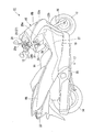
- FIG. 2 is a perspective view of a motorcycle to which the vehicle control system is applied. It is explanatory drawing of the main switch knob and smart key of the said motorcycle.
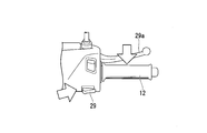
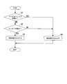
- FIG. 3 is an explanatory view around the starter switch of the motorcycle. It is a flowchart which shows the 1st control flow of the control system of the said vehicle. It is a flowchart which shows the 2nd control flow of the control system of the said vehicle. It is a graph which shows the output of the IMOAU terminal of the said vehicle control system.
- the vehicle control system 1 in the present embodiment includes a smart key system 2.
- the smart key system 2 is applied to, for example, a unit swing type scooter type motorcycle (saddle-ride type vehicle) 11.
- the motorcycle 11 includes a front wheel 13 that is a steered wheel and a rear wheel 14 that is a drive wheel.
- the front wheel 13 is supported by the front fork 16 and can be steered by the bar handle 12.
- the rear wheel 14 is supported by a swing unit 20 and can be driven by a reciprocating engine (an internal combustion engine, hereinafter simply referred to as an engine) 21.
- the swing unit 20 is integrally provided with an engine (see FIG. 1) 21 and, for example, a V-belt type continuously variable transmission (not shown).
- Steering system components including the bar handle 12, the front fork 16 and the front wheel 13 are supported by a front end portion of a vehicle body frame (not shown) so as to be steerable.
- the swing unit 20 and the rear wheel 14 are supported on the rear lower part of the vehicle body frame so as to be vertically swingable.
- a side stand 17 On the lower left side of the vehicle body frame, a side stand 17 that supports the vehicle body in an upright posture inclined to the left side is provided so as to be retractable.
- the periphery of the body frame is covered with a body cover 15.
- the motorcycle 11 includes a pair of left and right step floors 19 on which a driver sitting on a seat 18 places his / her feet, a center tunnel CT extending in the vehicle front-rear direction between the left and right step floors 19, and the front of the center tunnel CT and the left and right step floors 19. And a rear body RB connected to the rear of the center tunnel CT and the left and right step floors 19.
- a headlamp 22a and a front blinker 22b are arranged in the front upper part of the front body FB.
- a rear combination lamp 23 including a tail lamp, a brake lamp, and a rear turn signal is disposed at the rear part of the rear body RB.
- a seat 18 on which an occupant is seated is supported on the rear body RB.
- a fuel lid 24 that opens and closes the fuel filler opening arrangement space is provided.
- the seat 18 rotates up and down around a hinge shaft disposed at the front end, for example, and opens and closes the upper portion of the rear body RB.
- An article storage unit (not shown) is arranged below the sheet 18.
- the closed state in which the seat 18 closes the upper portion of the rear body RB see FIG. 1
- the occupant can sit on the seat 18.
- the open state in which the seat 18 opens the upper portion of the rear body RB the article storage section below the seat 18 can be accessed.
- the meter panel 26 is arranged on the upper part of the front body FB.
- a handle lock module 27 is accommodated inside the front body FB.
- the handle lock module 27 is integrally provided with a handle lock mechanism 28 that is a main body, a smart control unit 3 that will be described later, and a main switch 30 that is a main power switch of the motorcycle 11.
- the main switch 30 has a main switch knob 31 as an operation unit disposed on the inner panel 25 on the step floor 19 side (rear side) of the front body FB.
- the main switch knob 31 can be rotated or enabled in a state where ID authentication of a smart key (remote key) 4 described later is performed.
- the main switch 30 is turned on.
- power is supplied to the control device 40 described later.
- the engine 21 can be started, and an electromagnetic lock (an electric lock device operated by a solenoid) of the opening / closing body such as the seat 18 and the fuel lid 24 can be unlocked.
- the main switch knob 31 also serves as an operator for locking and unlocking the handle lock mechanism 28.
- the motorcycle 11 includes a smart key system 2 that enables locking and unlocking of each part of the vehicle.
- the smart key system 2 is a two-way communication between a smart key (portable device, FOB key) 4 held by a driver and a smart control unit (on-vehicle device, SCU) 3 mounted on the body of the motorcycle 11. And ID authentication of the smart key 4 is performed.
- the smart key system 2 can start the engine 21 and unlock each part of the vehicle when the smart key 4 is ID-authenticated.
- the engine 21 is started by holding the brake lever 29a on the right side of the bar handle 12 and pressing the starter switch 29 when the main switch 30 is turned on.
- the starter switch 29 is pressed, the engine start control unit 42 of the control device 40 starts the engine 21 by driving a starter motor 21a attached to the engine 21 and controlling ignition and fuel injection.
- the main switch knob 31 can be turned on (rotated to the on position P2) by the ID authentication of the smart key 4 (unlocked).
- the smart key 4 is released, the smart key 4 and the motorcycle are released. 11 becomes impossible or invalid due to loss of communication with the terminal 11 (locked state).
- the equipment that is unlocked and locked by turning on and off the main switch 30 includes, for example, a handle lock mechanism 28, a lock of the seat 18, a lock of the storage portion lid 26a disposed on the inner panel 25, a lock of the fuel lid 24, etc. There is.
- the smart key system 2 is triggered by an operation such as pressing of the main switch knob 31 or pressing of the operation button 4a of the smart key 4 when the smart key 4 in the power-on state enters the specified authentication area.
- Bidirectional communication between the smart key 4 and the smart control unit 3 is performed. Through this bidirectional communication, the smart control unit 3 reads the ID information of the smart key 4 and authenticates the smart key 4.
- the authentication area is, for example, a range having a radius of about 2 m with the vehicle body center as a base point.
- the smart key system 2 stops communication between the smart key 4 and the smart control unit 3 when the smart key 4 leaves the authentication area or when the power of the smart key 4 is turned off.
- the smart key system 2 also stops communication between the smart key 4 and the smart control unit 3 by turning off the main switch knob 31 (rotating operation to the off position P1).
- the main switch knob 31 is located between an off position P1 at which the main switch 30 is turned off, an on position P2 at which the main switch 30 is turned on, and between the off position P1 and the on position P2, and the seat 18 and the fuel lid 24.
- the seat / fuel lock release position P3 enabling the opening operation of the vehicle, and the lock position P4 that is rotated by being pushed from the off position P1 to the opposite side of the on position P2 to lock the vehicle parts including the handle lock. And have.
- the main switch knob 31 is in the seat / fuel lock release position P3, the operation of the seat / fuel lock release switch 32 adjacent to the main switch knob 31 is enabled or effective.
- the smart control unit 3 operates various notification means according to the operation of the transmission antenna and the reception unit for performing communication with the smart key 4, the control device 40, the locking device of each part of the vehicle, and the smart key system 2.
- Announcement drive device, etc. are connected (only the control device 40 is shown in FIG. 1).
- the notification drive device for example, a visual sign such as blinking a hazard lamp, and an auditory sign such as sounding an electronic sound, Execute at least one of the following (answerback). Thereby, the user can know that the locking device of each part of the vehicle has been locked and unlocked.
- the control device 40 is, for example, an integral ECU (Electric Control Unit) and functions as a control unit of the entire control system 1.
- An ON signal from the main switch 30 and an engine start signal from the starter switch 29 are input to the control device 40 through the smart control unit 3.
- a stand use detection signal from the side stand switch 17 a for detecting the standing state of the side stand 17, various detection signals for detecting the operating state of the engine 21, and the like are input to the control device 40.
- the control device 40 may be referred to as an engine control unit 40.
- the smart control unit 3 and the engine control unit 40 are collectively referred to as a control device 40A.
- the control device 40 includes an engine control unit 41 that controls driving of the engine 21, an engine start control unit 42 that performs start control of the engine 21, an operation detection / determination unit 43 that detects and determines the operating state of the engine 21, The communication state between the stand use control unit 44 that performs stop control of the engine 21 when the side stand 17 is used, the idle stop control unit 45 that performs idle stop control of the engine 21, and the smart key 4 and the smart control unit 3. And a communication state detection / determination means 46 for detection and determination.
- each said means with which the control apparatus 40 is provided is implement
- achieved by execution of a program for example, you may be comprised as hardware containing one or more electrical components, respectively.
- the control device 40 itself may be a unit divided into a plurality of units or a means realized by executing a program.
- the conventional smart key system has the following problems. That is, for example, after a user having the smart key 4 turns the main switch knob 31 after turning on the main switch 30 after ID authentication, the motorcycle 11 is started before the engine 21 is started without turning off the main switch 30. Let's say that In this case, in the conventional smart key system, even if the user who has the smart key 4 is absent, the engine 21 is started when a third party operates the starter switch 29.
- the side stand 17 is raised without turning off the main switch 30, the engine 21 is stopped, and the side stand 17 is used. Assume that the motorcycle 11 is left in a stopped state. Also in this case, in the conventional smart key system, a third party starts the engine 21 as described above.
- the smart key system 2 of the present embodiment even after the smart key 4 is authenticated and the main switch 30 is turned on, the smart key 4 is moved away from the authentication area. When the communication with the engine 4 becomes impossible, the engine 21 is controlled not to be started.
- the engine 21 is stopped by turning off the main switch 30 or the like. Even in such a case, control for permitting restart of the engine 21 is performed under the prescribed conditions.
- the control shown in FIG. 5 is a control for disabling engine start in the engine control unit 40 when the smart key 4 becomes incapable of communication when the engine is stopped when the main switch 30 is on.
- the control shown in FIG. 6 is a control for enabling the engine to be started under the prescribed conditions even when the engine is stopped in the smart control unit 3 after the smart key 4 becomes unable to communicate during engine operation. .
- step S1 This determination is made based on whether or not the idle stop control unit 45 is operating. If the idle stop state is set (YES in step S1), the output from the IMOAU terminal is stopped (step S4).
- the IMOAU terminal output is a signal transmitted from the engine control unit 40 to the smart control unit 3 and indicating that the engine is in an engine stop state (an engine stall state or a stop state) that is not an idle stop.
- step S2 determines whether or not the current engine 21 is in the stalled state. This determination is performed by determining whether or not the operating state of the engine 21 is equal to or higher than a predetermined engine stall determination value (for example, whether or not the engine speed is equal to or higher than the idle speed) in the operating state detection / determination unit 43. Made.
- a predetermined engine stall determination value for example, whether or not the engine speed is equal to or higher than the idle speed
- step S2 when the engine 21 is in the stalled state (YES in step S2), that is, when the condition that the engine 21 is in the stalled state other than the idle stop state is satisfied, the output of the IMOAU terminal is set to 100 ms.
- a rectangular wave output of ⁇ 4 ms is set (step S3).
- the control device 40A disables starting of the engine 21 when communication with the smart key 4 becomes impossible when there is an output from the IMOAU terminal. Thus, even if the user leaves the motorcycle 11 without turning off the main switch 30 (the control device 40A remains on), the engine start by a third party is prevented, and the anti-theft and convenience are improved. .
- the smart control unit 3 receiving the output from the IMOAU terminal starts the control shown in FIG. That is, the smart control unit 3 first determines whether or not there is an output from the IMOAU terminal (step S11). This determination corresponds to, for example, determination of whether or not the engine is in a stopped state due to use of the side stand 17. In this case, in step S11, it is determined whether or not the stand use control unit 44 is operating. As a premise, the control device 40A stops the IMOAU output when the side stand 17 is not out (when the stand is stored).
- step S11 the process proceeds to step S12 to execute a drop detection mode for detecting the drop of the smart key 4.
- the smart control unit 3 determines whether or not communication with the smart key 4 is possible.
- the smart control unit 3 may include that the communication with the smart key 4 is interrupted when the operating state of the engine 21 or the vehicle speed is equal to or higher than a specified value (during traveling) as a condition for shifting to the fall detection mode.
- the smart control unit 3 may include a communication state detection / determination unit 46.
- step S13 it is determined whether or not the fall detection is confirmed in step S13.
- the smart control unit 3 determines the drop detection of the smart key 4 when communication with the smart key 4 continues for a specified time of about 10 seconds or longer.
- a starter signal (a signal for driving the starter motor 21a) is output when the starter switch 29 is input (during a pressing operation). Thereby, the cranking of the engine 21 is performed and the engine 21 is started.
- step S13 If the fall detection is not confirmed (NO in step S13), the process proceeds to step S16 to determine whether the smart key 4 is authenticated (whether the smart key 4 is close (in the authentication area)). .
- the control device 40A stops other processes until the authentication of the smart key 4 is completed.
- step S16 If YES in step S16 (smart key 4 is nearby), the process proceeds to step S17, and similarly to step S14, a starter signal is output when the starter switch 29 is input, and the engine 21 is started. If NO in step S16 (the smart key 4 is not nearby), the process proceeds to step S18, and no starter signal is output even when the starter switch 29 is input, and the engine 21 cannot be started.
- step S11 if YES in step S11 (the side stand 17 is out and the engine is stopped), the process proceeds to step S15 to determine whether or not the drop detection of the smart key 4 is confirmed. If the fall detection has been confirmed (YES in step S15), the process proceeds to step S19, and similarly to steps S14 and S17, a starter signal is output when the starter switch 29 is input, and the engine 21 is started. If drop detection has not been confirmed (NO in step S15), the process proceeds to step S16, and the process described above is performed.
- the control device 40A blinks the indicator lamp in the meter panel 26 when the drop detection of the smart key 4 is confirmed. This notifies the user that the smart key 4 has been dropped.
- the control device 40A blinks a buzzer or a hazard lamp in addition to the indicator lamp. This strongly notifies the user that the smart key 4 has been dropped (notification state).
- the starter switch 29 is pressed for more than a specified time of about 2 seconds or more than a specified time of about 20 seconds in the notification state. Locking is performed according to conditions such as elapse of time.
- the “specified condition” includes at least one of the following “specified state” and “specified operation”. Examples of the “prescribed state” include a stop state after communication with the smart key 4 is interrupted during traveling, and within a predetermined time from the stop of the engine 21. It is done.
- the “specified operation” means, for example, a long press of the starter switch 29, a repeated operation of an existing operation element such as the starter switch 29, an accelerator grip, a brake operation element, and a clutch operation element, or a dedicated re-operation. The operation with respect to the start operation element, etc. are mentioned.
- the vehicle control system 1 in the above embodiment includes the smart key system 2 that performs authentication by communication between the motorcycle 11 and the smart key 4 within the preset authentication area, and the smart key.
- the main switch 30 that can be turned on when the system 2 is authenticated, the control device 40A that is turned on by turning on the main switch 30, and controls the motorcycle 11, and the control device 40A is in the on state.
- a starter motor 21a for starting the engine 21 of the motorcycle 11, and the control device 40A includes an operation state detection / determination unit 43 for determining an operation state of the engine 21, and the smart key system 2
- a communication state detection / determination unit 46 for determining a communication state with the smart key 4 in The control device 40A is in an ON state, and when the operation state detection / determination unit 43 determines that the engine 21 is not in operation, the communication state detection / determination unit 46 communicates with the smart key 4 When it is determined that there is no communication between them, the starter motor 21a cannot start the engine 21.
- the control device 40A even when the control device 40A is in an on state, such as when the engine 21 is temporarily stopped or before the engine 21 is started, the user holding the smart key 4 leaves the motorcycle 11 (authentication). If the smart key 4 is no longer authenticated due to going out of the area or the like, the engine 21 can be prevented from starting. That is, even if the control device 40A is not turned off, the engine 21 cannot be started if authentication by the smart key system 2 is not performed. For this reason, even if the user leaves the motorcycle 11 while the control device 40A is on, it is possible to prevent a third party from starting the engine 21 and improve the anti-theft and convenience.
- the control device 40A includes a stand use control unit 44 that stops the engine 21 when the side stand 17 that locks the motorcycle 11 is used, and the control device 40A includes:
- the engine 21 is stopped by the stand use control unit 44
- the engine by the starter motor 21a is determined when the communication state detection / determination unit 46 determines that communication with the smart key 4 is lost. 21 cannot be started.
- the authentication of the smart key 4 is not performed when the user who has the smart key 4 leaves the motorcycle 11 or the like. Can be prevented from starting. For this reason, even if the user leaves the motorcycle 11 while the control device 40A is on, it is possible to prevent a third party from starting the engine 21 and improve the anti-theft and convenience.
- the control device 40 ⁇ / b> A determines that the communication state detection / determination unit 46 has lost communication with the smart key 4 while the engine 21 is being driven.
- the engine 21 can be started by the starter motor 21a under specified conditions. According to this configuration, even when it is detected that communication with the smart key 4 has stopped due to the smart key 4 being dropped and lost during traveling, the engine 21 can be restarted under specified conditions. Is possible. For this reason, even when the engine 21 is stopped without noticing the loss of the smart key 4, the engine 21 can be restarted and the convenience can be improved.
- the control device 40 ⁇ / b> A determines whether communication with the smart key 4 is lost when the operating state of the engine 21 is equal to or greater than a predetermined value. To do. According to this configuration, it is possible to reduce the processing load of the control device 40 ⁇ / b> A by restricting the smart key 4 from being dropped to a predetermined value or more corresponding to the traveling of the motorcycle 11. In addition, it is possible to distinguish the situation where the user who has the smart key 4 leaves the motorcycle 11 at the time of stopping, and to improve the reliability of the smart key 4 fall determination.
- the engine 21 is an internal combustion engine
- the control device 40A includes an idle stop control unit 45 that automatically stops the internal combustion engine
- the control device 40A When the state detection / determination unit 43 determines that the engine 21 is non-operating and is not in the non-operational state by the idle stop control unit 45, the communication state detection / determination unit 46 is connected to the smart key 4. If the starter motor 21a determines that the communication is lost, the start of the engine 21 is disabled. According to this configuration, only when the internal combustion engine is not in the idle stop state, the engine 21 can be disabled when the smart key 4 is no longer authenticated. As a result, it is possible to provide a favorable traveling environment without hindering restart of the internal combustion engine after the idle stop, and the merchantability of the motorcycle 11 can be improved.
- the present invention is not limited to the above-described embodiment.
- the present system is not limited to application to motorcycles, but can be widely applied to saddle riding type vehicles.
- the saddle riding type vehicle includes all vehicles on which the driver rides across the vehicle body, and includes not only motorcycles (including motorbikes and scooter type vehicles), but also three-wheelers (in addition to front and rear two wheels). , Including two front wheels and one rear wheel vehicle) or four wheel vehicles.
- the configuration in the above embodiment is an example of the present invention, and various modifications can be made without departing from the gist of the present invention, such as replacing the component of the embodiment with a known component.
- Vehicle control system Smart key system (authentication means) 3 Smart control unit 4 Smart key (remote key) 11 Motorcycle (vehicle) 17 Side stand (stand) 21 Engine (drive source, internal combustion engine) 21a Starter motor (drive source starting means) 30 Main switch 31 Main switch knob 40A Control device (control means) 40 Control device (engine control unit) 43 Operating state detection / determination unit (operating state determination means) 44 Control unit when using stand (control means when using stand) 45 Idle stop control unit (idle stop control means) 46 Communication state detection / determination unit (communication state determination means)
Landscapes
- Engineering & Computer Science (AREA)
- Mechanical Engineering (AREA)
- Automation & Control Theory (AREA)
- Computer Networks & Wireless Communication (AREA)
- Physics & Mathematics (AREA)
- General Physics & Mathematics (AREA)
- Combustion & Propulsion (AREA)
- Chemical & Material Sciences (AREA)
- General Engineering & Computer Science (AREA)
- Transportation (AREA)
- Human Computer Interaction (AREA)
- Lock And Its Accessories (AREA)
- Control Of Vehicle Engines Or Engines For Specific Uses (AREA)
Abstract
Description
本願は、2018年4月9日に、日本に出願された特願2018-075031号に基づき優先権を主張し、その内容をここに援用する。
一方、自動二輪車等の鞍乗り型車両では、メインスイッチのみならず、サイドスタンドスイッチによってもエンジンストップがなされる。このような場合、車両各部の施錠がなされない事象が発生する。この事象は、メインスイッチを切ることなく、リモートキーを所有する使用者が車両から遠ざかった場合、ECUの電源がON状態のままであるときに発生する。この場合、第三者がエンジンを始動可能となるため、防盗性の面で課題がある。また、車両から離れる度にメインスイッチを切ることは、利便性の面で課題がある。
この構成によれば、駆動源の一時的な停止時や駆動源の始動前等に、制御手段がオン状態であっても、リモートキーを所持した使用者が車両から離れる(認証エリア外に出る)等によって、リモートキーの認証がなされなくなった場合には、駆動源を始動させなくすることが可能となる。つまり、制御手段をオフ操作しなくても、認証手段による認証がなされなくなった場合には、駆動源の始動が不能となる。このため、制御手段がオン状態のまま使用者が車両から離れても、第三者が駆動源を始動させてしまうことを防止し、防盗性および利便性を向上させることができる。
本発明の第二の態様は、上記第一の態様において、前記制御手段(40A)は、前記車両(11)を係止するスタンド(17)の使用時に前記駆動源(21)を停止させるスタンド使用時制御手段(44)を備え、前記制御手段(40A)は、前記スタンド使用時制御手段(44)において前記駆動源(21)を停止させたとき、前記通信状態判定手段(46)において前記リモートキー(4)との間の通信がなくなったと判定した場合に、前記駆動源始動手段(21a)による前記駆動源(21)の始動を不可とする。
この構成によれば、スタンドの使用による駆動源の停止時において、リモートキーを所持した使用者が車両から離れる等によって、リモートキーの認証がなされなくなった場合には、駆動源を始動させなくすることが可能となる。このため、制御手段がオン状態のまま使用者が車両から離れても、第三者が駆動源を始動させてしまうことを防止し、防盗性および利便性を向上させることができる。
本発明の第三の態様は、上記第一又は第二の態様において、前記制御手段(40A)は、前記通信状態判定手段(46)において前記駆動源(21)の駆動中に前記リモートキー(4)との間の通信がなくなったと判定したとき、前記駆動源(21)を停止させた際に規定の条件下で前記駆動源始動手段(21a)による前記駆動源(21)の始動を可能とする。
この構成によれば、走行中にリモートキーを落下させて紛失する等により、リモートキーとの間の通信が停止したことを検知した場合にも、規定の条件下で駆動源の再始動が可能となる。このため、リモートキーの紛失に気付かず駆動源を停止させた場合等にも、駆動源の再始動を可能とし、利便性を向上させることができる。
本発明の第四の態様は、上記第三の態様において、前記制御手段(40A)は、前記駆動源(21)の稼動状態が予め定めた規定値以上であるときに、前記リモートキー(4)との間の通信がなくなったか否かを判定する。
この構成によれば、リモートキーの落下判定の実施を車両の走行中に相当する規定値以上に制限することで、制御手段の処理負荷の軽減を図ることができる。また、停車相当時にリモートキーを所持した使用者が車両から離れるといった状況と区別し、リモートキーの落下判定の確実性を高めることができる。
本発明の第五の態様は、上記第一から第四の態様の何れか一つにおいて、前記駆動源(21)は内燃機関であり、前記制御手段(40A)は、前記内燃機関を自動的に停止させるアイドルストップ制御手段(45)を備え、前記制御手段(40A)は、前記稼動状態判定手段(43)において前記駆動源(21)が非稼動と判定したときで、かつ前記アイドルストップ制御手段(45)による状態ではないとき、前記通信状態判定手段(46)において前記リモートキー(4)との間の通信がなくなったと判定した場合に、前記駆動源始動手段(21a)による前記駆動源(21)の始動を不可とする。
この構成によれば、内燃機関のアイドルストップ状態ではないときに限定して、リモートキーの認証がなされなくなった場合に駆動源の始動を不可とすることが可能となる。これにより、内燃機関のアイドルストップ後の再始動を妨げることなく、良好な走行環境の提供が可能となり、車両の商品性を向上させることができる。
図1、図2に示すように、本実施形態における車両の制御システム1は、スマートキーシステム2を含んでいる。スマートキーシステム2は、例えばユニットスイング式のスクータ型の自動二輪車(鞍乗り型車両)11に適用される。
図2に示すように、自動二輪車11は、操向輪である前輪13と、駆動輪である後輪14と、を備えている。前輪13は、フロントフォーク16に支持され、バーハンドル12によって操向可能である。後輪14は、スイングユニット20に支持され、レシプロエンジン(内燃機関、以下、単にエンジンという。)21によって駆動可能である。スイングユニット20は、エンジン(図1参照)21と、例えばVベルト式の無段変速機(不図示)と、を一体に備えている。
図1に示すように、自動二輪車11は、車両各部のロックおよびアンロックを可能とするスマートキーシステム2を備えている。
スマートキーシステム2は、運転者が保持するスマートキー(携帯機器、FOBキー)4と、自動二輪車11の車体に搭載されたスマートコントロールユニット(車載機器、SCU)3と、の間で双方向通信を行い、スマートキー4のID認証を行う。スマートキーシステム2は、スマートキー4のID認証がなされた場合に、エンジン21の始動や車両各部の解錠を可能とする。
従来のスマートキーシステムでは以下の課題が考えられる。
すなわち、例えば、スマートキー4を所持した使用者が、ID認証後にメインスイッチノブ31を回してメインスイッチ30をオン状態とした後、メインスイッチ30を切ることなくエンジン21の始動前に自動二輪車11を離れたとする。この場合、従来のスマートキーシステムでは、スマートキー4を所持した使用者が不在の状況でも、第三者がスタータスイッチ29を操作するとエンジン21を始動させてしまう。
次に、制御装置40Aにおいて行われる処理について、図5、図6のフローチャートを参照して説明する。
図5に示す制御は、エンジンコントロールユニット40において、メインスイッチ30のオン状態でのエンジン停止時に、スマートキー4が通信不能となったことに伴いエンジン始動を不能とするための制御である。図6に示す制御は、スマートコントロールユニット3において、エンジン駆動中にスマートキー4が通信不能となった後にエンジン停止した場合にも、規定の条件下でエンジン始動を可能とするための制御である。
ステップS16でNO(スマートキー4が近くにない)の場合、ステップS18に移行し、スタータスイッチ29の入力時にもスタータ信号を出力せず、エンジン21の始動を不能とする。
スマートキー4の落下検知が確定した場合、停車時等にメインスイッチ30のオフ操作がなされると、制御装置40Aは、インジケータランプに加え、例えばハザードランプが点滅したりブザーが吹鳴したりする。これにより、使用者にスマートキー4の落下を強く告知する(告知状態)。
前記「規定の条件」には、以下の「規定の状態」および「規定の動作」の少なくとも一方が含まれている。前記「規定の状態」とは、例えば、走行中にスマートキー4との間の通信が途絶えた後の停車状態であること、エンジン21の停止から予め定めた時間内にあること、等が挙げられる。前記「規定の操作」とは、例えば、スタータスイッチ29の長押しの他、スタータスイッチ29、アクセルグリップ、ブレーキ操作子、クラッチ操作子といった既存の操作子に対する数回の繰り返し操作、あるいは専用の再始動操作子に対する操作、等が挙げられる。
この構成によれば、サイドスタンド17の使用によるエンジン21の停止時において、スマートキー4を所持した使用者が自動二輪車11から離れる等によって、スマートキー4の認証がなされなくなった場合には、エンジン21を始動させなくすることが可能となる。このため、制御装置40Aがオン状態のまま使用者が自動二輪車11から離れても、第三者がエンジン21を始動させてしまうことを防止し、防盗性および利便性を向上させることができる。
この構成によれば、走行中にスマートキー4を落下させて紛失する等により、スマートキー4との間の通信が停止したことを検知した場合にも、規定の条件下でエンジン21の再始動が可能となる。このため、スマートキー4の紛失に気付かずエンジン21を停止させた場合等にも、エンジン21の再始動を可能とし、利便性を向上させることができる。
この構成によれば、スマートキー4の落下判定の実施を自動二輪車11の走行中に相当する規定値以上に制限することで、制御装置40Aの処理負荷の軽減を図ることができる。また、停車相当時にスマートキー4を所持した使用者が自動二輪車11から離れるといった状況と区別し、スマートキー4の落下判定の確実性を高めることができる。
この構成によれば、内燃機関のアイドルストップ状態ではないときに限定して、スマートキー4の認証がなされなくなった場合にエンジン21の始動を不可とすることが可能となる。これにより、内燃機関のアイドルストップ後の再始動を妨げることなく、良好な走行環境の提供が可能となり、自動二輪車11の商品性を向上させることができる。
そして、上記実施形態における構成は本発明の一例であり、実施形態の構成要素を周知の構成要素に置き換える等、本発明の要旨を逸脱しない範囲で種々の変更が可能である。
2 スマートキーシステム(認証手段)
3 スマートコントロールユニット
4 スマートキー(リモートキー)
11 自動二輪車(車両)
17 サイドスタンド(スタンド)
21 エンジン(駆動源、内燃機関)
21a スタータモータ(駆動源始動手段)
30 メインスイッチ
31 メインスイッチノブ
40A 制御装置(制御手段)
40 制御装置(エンジンコントロールユニット)
43 稼動状態検知・判定部(稼動状態判定手段)
44 スタンド使用時制御部(スタンド使用時制御手段)
45 アイドルストップ制御部(アイドルストップ制御手段)
46 通信状態検知・判定部(通信状態判定手段)
Claims (5)
- 予め設定された認証エリア内で車両(11)とリモートキー(4)との間の通信によって認証を行う認証手段(2)と、
前記認証手段(2)の認証時にオン操作可能となるメインスイッチ(30)と、
前記メインスイッチ(30)のオン操作によりオン状態となって前記車両(11)の制御を行う制御手段(40A)と、
前記制御手段(40A)がオン状態にあるときに前記車両(11)の駆動源(21)の始動を行う駆動源始動手段(21a)と、を備え、
前記制御手段(40A)は、
前記駆動源(21)の稼動状態を判定する稼動状態判定手段(43)と、
前記認証手段(2)における前記リモートキー(4)との間の通信状態を判定する通信状態判定手段(46)と、を備え、
前記制御手段(40A)は、前記制御手段(40A)がオン状態であり、前記稼動状態判定手段(43)において前記駆動源(21)が非稼動と判定したとき、前記通信状態判定手段(46)において前記リモートキー(4)との間の通信がなくなったと判定した場合に、前記駆動源始動手段(21a)による前記駆動源(21)の始動を不可とする車両の制御システム。 - 前記制御手段(40A)は、前記車両(11)を係止するスタンド(17)の使用時に前記駆動源(21)を停止させるスタンド使用時制御手段(44)を備え、
前記制御手段(40A)は、前記スタンド使用時制御手段(44)において前記駆動源(21)を停止させたとき、前記通信状態判定手段(46)において前記リモートキー(4)との間の通信がなくなったと判定した場合に、前記駆動源始動手段(21a)による前記駆動源(21)の始動を不可とする請求項1に記載の車両の制御システム。 - 前記制御手段(40A)は、前記通信状態判定手段(46)において前記駆動源(21)の駆動中に前記リモートキー(4)との間の通信がなくなったと判定したとき、前記駆動源(21)を停止させた際に規定の条件下で前記駆動源始動手段(21a)による前記駆動源(21)の始動を可能とする請求項1又は2に記載の車両の制御システム。
- 前記制御手段(40A)は、前記駆動源(21)の稼動状態が予め定めた規定値以上であるときに、前記リモートキー(4)との間の通信がなくなったか否かを判定する請求項3に記載の車両の制御システム。
- 前記駆動源(21)は内燃機関であり、
前記制御手段(40A)は、前記内燃機関を自動的に停止させるアイドルストップ制御手段(45)を備え、
前記制御手段(40A)は、前記稼動状態判定手段(43)において前記駆動源(21)が非稼動と判定したときで、かつ前記アイドルストップ制御手段(45)による状態ではないとき、前記通信状態判定手段(46)において前記リモートキー(4)との間の通信がなくなったと判定した場合に、前記駆動源始動手段(21a)による前記駆動源(21)の始動を不可とする請求項1から4の何れか一項に記載の車両の制御システム。
Priority Applications (4)
| Application Number | Priority Date | Filing Date | Title |
|---|---|---|---|
| JP2020513225A JP7179053B2 (ja) | 2018-04-09 | 2019-04-03 | 鞍乗り型車両の制御システム |
| BR112020020494-3A BR112020020494B1 (pt) | 2018-04-09 | 2019-04-03 | Sistema de controle de veículo |
| CN201980022716.2A CN111918798B (zh) | 2018-04-09 | 2019-04-03 | 跨骑型车辆的控制系统 |
| US17/045,773 US11398119B2 (en) | 2018-04-09 | 2019-04-03 | Vehicle control system |
Applications Claiming Priority (2)
| Application Number | Priority Date | Filing Date | Title |
|---|---|---|---|
| JP2018-075031 | 2018-04-09 | ||
| JP2018075031 | 2018-04-09 |
Publications (1)
| Publication Number | Publication Date |
|---|---|
| WO2019198599A1 true WO2019198599A1 (ja) | 2019-10-17 |
Family
ID=68164097
Family Applications (1)
| Application Number | Title | Priority Date | Filing Date |
|---|---|---|---|
| PCT/JP2019/014840 Ceased WO2019198599A1 (ja) | 2018-04-09 | 2019-04-03 | 車両の制御システム |
Country Status (5)
| Country | Link |
|---|---|
| US (1) | US11398119B2 (ja) |
| JP (1) | JP7179053B2 (ja) |
| CN (1) | CN111918798B (ja) |
| TW (1) | TWI714047B (ja) |
| WO (1) | WO2019198599A1 (ja) |
Cited By (3)
| Publication number | Priority date | Publication date | Assignee | Title |
|---|---|---|---|---|
| JPWO2023042706A1 (ja) * | 2021-09-16 | 2023-03-23 | ||
| WO2023042706A1 (ja) * | 2021-09-16 | 2023-03-23 | ヤマハ発動機株式会社 | Mt型リーン車両 |
| JP2024092384A (ja) * | 2022-12-26 | 2024-07-08 | 本田技研工業株式会社 | 車両制御装置、車両制御方法、及びプログラム |
Families Citing this family (5)
| Publication number | Priority date | Publication date | Assignee | Title |
|---|---|---|---|---|
| TWI739511B (zh) * | 2020-07-10 | 2021-09-11 | 三陽工業股份有限公司 | 車輛解鎖裝置 |
| CN113053001A (zh) * | 2021-03-31 | 2021-06-29 | 雅迪科技集团有限公司 | 一种电动车蓝牙解锁系统、方法及使用旋钮锁上下电方法 |
| TWI779685B (zh) * | 2021-06-24 | 2022-10-01 | 光陽工業股份有限公司 | 電動機車的控制系統 |
| TWI881397B (zh) * | 2022-11-09 | 2025-04-21 | 啟碁科技股份有限公司 | 交通工具遙控系統及其運作方法 |
| DE102024103450A1 (de) * | 2024-02-08 | 2025-08-14 | Bayerische Motoren Werke Aktiengesellschaft | Verfahren zum Steuern eines Verriegelungssystems, Steuerungssystem sowie Kraftrad |
Citations (5)
| Publication number | Priority date | Publication date | Assignee | Title |
|---|---|---|---|---|
| JP2006199168A (ja) * | 2005-01-21 | 2006-08-03 | Kawasaki Heavy Ind Ltd | レジャービィークルの盗難防止装置 |
| JP2006214357A (ja) * | 2005-02-03 | 2006-08-17 | Mazda Motor Corp | 車両用アイドルストップスタート制御装置 |
| JP2009196406A (ja) * | 2008-02-19 | 2009-09-03 | Yamaha Motor Co Ltd | 車両制御装置、及び鞍乗型車両 |
| JP2014020208A (ja) * | 2012-07-12 | 2014-02-03 | Yamaha Motor Co Ltd | 車両情報管理システム。 |
| JP2017019359A (ja) * | 2015-07-09 | 2017-01-26 | ヤマハ発動機株式会社 | 鞍乗型車両用認証システム及び鞍乗型車両 |
Family Cites Families (13)
| Publication number | Priority date | Publication date | Assignee | Title |
|---|---|---|---|---|
| JP4100568B2 (ja) * | 2003-09-29 | 2008-06-11 | 本田技研工業株式会社 | 車両用リモートキー |
| JP4800138B2 (ja) * | 2006-08-01 | 2011-10-26 | ヤマハ発動機株式会社 | 車両制御装置およびそれを備えた車両 |
| JP5197936B2 (ja) * | 2006-08-02 | 2013-05-15 | ヤマハ発動機株式会社 | 車両制御装置およびそれを備えた車両 |
| JP4801580B2 (ja) * | 2006-12-25 | 2011-10-26 | 本田技研工業株式会社 | 自動二輪車のハンドルロック装置 |
| JP5903415B2 (ja) * | 2013-09-05 | 2016-04-13 | 本田技研工業株式会社 | スマートエントリシステム |
| JP6118298B2 (ja) * | 2014-09-30 | 2017-04-19 | 本田技研工業株式会社 | 鞍乗車両 |
| US9996998B2 (en) * | 2014-12-05 | 2018-06-12 | HomeAway.com, Inc. | Adaptive advisory engine and methods to predict preferential activities available at a region associated with lodging |
| JP6228952B2 (ja) * | 2015-07-09 | 2017-11-08 | ヤマハ発動機株式会社 | 鞍乗型車両用認証システム及び鞍乗型車両 |
| US10574445B2 (en) * | 2016-12-21 | 2020-02-25 | Intel IP Corporation | Range constrained device configuration |
| PH12019501866B1 (en) * | 2017-04-05 | 2023-08-04 | Gogoro Inc | Systems for operating a vehicle and associated methods |
| JP7221589B2 (ja) * | 2017-10-24 | 2023-02-14 | トヨタ自動車株式会社 | 鍵情報管理装置、鍵情報管理方法、鍵情報管理プログラム |
| US10328900B1 (en) * | 2017-12-04 | 2019-06-25 | Lear Corporation | System and methods for vehicle passive keyless entry triggered by smartphone proximity detection |
| KR102485246B1 (ko) * | 2017-12-05 | 2023-01-06 | 현대자동차주식회사 | 차량 및 그 제어방법 |
-
2019
- 2019-04-03 TW TW108112046A patent/TWI714047B/zh active
- 2019-04-03 US US17/045,773 patent/US11398119B2/en active Active
- 2019-04-03 CN CN201980022716.2A patent/CN111918798B/zh active Active
- 2019-04-03 WO PCT/JP2019/014840 patent/WO2019198599A1/ja not_active Ceased
- 2019-04-03 JP JP2020513225A patent/JP7179053B2/ja active Active
Patent Citations (5)
| Publication number | Priority date | Publication date | Assignee | Title |
|---|---|---|---|---|
| JP2006199168A (ja) * | 2005-01-21 | 2006-08-03 | Kawasaki Heavy Ind Ltd | レジャービィークルの盗難防止装置 |
| JP2006214357A (ja) * | 2005-02-03 | 2006-08-17 | Mazda Motor Corp | 車両用アイドルストップスタート制御装置 |
| JP2009196406A (ja) * | 2008-02-19 | 2009-09-03 | Yamaha Motor Co Ltd | 車両制御装置、及び鞍乗型車両 |
| JP2014020208A (ja) * | 2012-07-12 | 2014-02-03 | Yamaha Motor Co Ltd | 車両情報管理システム。 |
| JP2017019359A (ja) * | 2015-07-09 | 2017-01-26 | ヤマハ発動機株式会社 | 鞍乗型車両用認証システム及び鞍乗型車両 |
Cited By (6)
| Publication number | Priority date | Publication date | Assignee | Title |
|---|---|---|---|---|
| JPWO2023042706A1 (ja) * | 2021-09-16 | 2023-03-23 | ||
| WO2023042706A1 (ja) * | 2021-09-16 | 2023-03-23 | ヤマハ発動機株式会社 | Mt型リーン車両 |
| WO2023042325A1 (ja) * | 2021-09-16 | 2023-03-23 | ヤマハ発動機株式会社 | リーン車両 |
| JP7803955B2 (ja) | 2021-09-16 | 2026-01-21 | ヤマハ発動機株式会社 | マニュアルトランスミッション型リーン車両 |
| JP2024092384A (ja) * | 2022-12-26 | 2024-07-08 | 本田技研工業株式会社 | 車両制御装置、車両制御方法、及びプログラム |
| JP7574270B2 (ja) | 2022-12-26 | 2024-10-28 | 本田技研工業株式会社 | 車両制御装置、車両制御方法、及びプログラム |
Also Published As
| Publication number | Publication date |
|---|---|
| BR112020020494A2 (pt) | 2021-01-12 |
| TWI714047B (zh) | 2020-12-21 |
| US20210158640A1 (en) | 2021-05-27 |
| CN111918798A (zh) | 2020-11-10 |
| JPWO2019198599A1 (ja) | 2021-03-11 |
| CN111918798B (zh) | 2022-12-02 |
| TW201946811A (zh) | 2019-12-16 |
| JP7179053B2 (ja) | 2022-11-28 |
| US11398119B2 (en) | 2022-07-26 |
Similar Documents
| Publication | Publication Date | Title |
|---|---|---|
| JP7179053B2 (ja) | 鞍乗り型車両の制御システム | |
| US8237543B2 (en) | Motorcycle | |
| JP3844231B2 (ja) | 自動二輪車の盗難防止装置 | |
| JP4603928B2 (ja) | 車両用盗難防止システム | |
| ITRM20070191A1 (it) | Electronic authentication system for motorcycle | |
| JP2006199168A (ja) | レジャービィークルの盗難防止装置 | |
| JP5803877B2 (ja) | 車両用電源制御装置 | |
| US11167764B2 (en) | Vehicle control system | |
| WO2020202343A1 (ja) | 解錠システム | |
| CN116615593B (zh) | 跨骑型车辆及存储介质 | |
| JP4802827B2 (ja) | 自動二輪車の緊急解錠システム | |
| JP7117339B2 (ja) | 鞍乗型車両の認証装置 | |
| EP3239026B1 (en) | Vehicle | |
| JP2007153190A (ja) | 車両用始動装置 | |
| JP7366291B2 (ja) | 車載通信システム、鞍乗型車両、およびプログラム | |
| JP2006315582A (ja) | 車両エンジン制御システム | |
| JP3886044B2 (ja) | 自動二輪車における盗難防止装置 | |
| JP7531629B2 (ja) | 車両、車載機器、およびプログラム | |
| BR112020020494B1 (pt) | Sistema de controle de veículo | |
| JP2023178716A (ja) | 運転可否判定装置 | |
| WO2023238816A1 (ja) | 運転可否判定装置 | |
| JP2017114235A (ja) | 車両制御装置 | |
| JPH01215649A (ja) | 自動車用盗難防止装置 |
Legal Events
| Date | Code | Title | Description |
|---|---|---|---|
| 121 | Ep: the epo has been informed by wipo that ep was designated in this application |
Ref document number: 19784582 Country of ref document: EP Kind code of ref document: A1 |
|
| ENP | Entry into the national phase |
Ref document number: 2020513225 Country of ref document: JP Kind code of ref document: A |
|
| NENP | Non-entry into the national phase |
Ref country code: DE |
|
| REG | Reference to national code |
Ref country code: BR Ref legal event code: B01A Ref document number: 112020020494 Country of ref document: BR |
|
| ENP | Entry into the national phase |
Ref document number: 112020020494 Country of ref document: BR Kind code of ref document: A2 Effective date: 20201006 |
|
| 122 | Ep: pct application non-entry in european phase |
Ref document number: 19784582 Country of ref document: EP Kind code of ref document: A1 |