WO2019189449A1 - プレフィルドシリンジ、薬液投与システム及びシリンジポンプ - Google Patents
プレフィルドシリンジ、薬液投与システム及びシリンジポンプ Download PDFInfo
- Publication number
- WO2019189449A1 WO2019189449A1 PCT/JP2019/013334 JP2019013334W WO2019189449A1 WO 2019189449 A1 WO2019189449 A1 WO 2019189449A1 JP 2019013334 W JP2019013334 W JP 2019013334W WO 2019189449 A1 WO2019189449 A1 WO 2019189449A1
- Authority
- WO
- WIPO (PCT)
- Prior art keywords
- barrel
- rfid tag
- syringe
- prefilled syringe
- antenna
- Prior art date
Links
Images


Classifications
-
- A—HUMAN NECESSITIES
- A61—MEDICAL OR VETERINARY SCIENCE; HYGIENE
- A61M—DEVICES FOR INTRODUCING MEDIA INTO, OR ONTO, THE BODY; DEVICES FOR TRANSDUCING BODY MEDIA OR FOR TAKING MEDIA FROM THE BODY; DEVICES FOR PRODUCING OR ENDING SLEEP OR STUPOR
- A61M5/00—Devices for bringing media into the body in a subcutaneous, intra-vascular or intramuscular way; Accessories therefor, e.g. filling or cleaning devices, arm-rests
- A61M5/178—Syringes
- A61M5/31—Details
- A61M5/3129—Syringe barrels
- A61M5/3135—Syringe barrels characterised by constructional features of the proximal end
-
- A—HUMAN NECESSITIES
- A61—MEDICAL OR VETERINARY SCIENCE; HYGIENE
- A61M—DEVICES FOR INTRODUCING MEDIA INTO, OR ONTO, THE BODY; DEVICES FOR TRANSDUCING BODY MEDIA OR FOR TAKING MEDIA FROM THE BODY; DEVICES FOR PRODUCING OR ENDING SLEEP OR STUPOR
- A61M5/00—Devices for bringing media into the body in a subcutaneous, intra-vascular or intramuscular way; Accessories therefor, e.g. filling or cleaning devices, arm-rests
- A61M5/14—Infusion devices, e.g. infusing by gravity; Blood infusion; Accessories therefor
- A61M5/142—Pressure infusion, e.g. using pumps
- A61M5/145—Pressure infusion, e.g. using pumps using pressurised reservoirs, e.g. pressurised by means of pistons
- A61M5/1452—Pressure infusion, e.g. using pumps using pressurised reservoirs, e.g. pressurised by means of pistons pressurised by means of pistons
-
- A—HUMAN NECESSITIES
- A61—MEDICAL OR VETERINARY SCIENCE; HYGIENE
- A61M—DEVICES FOR INTRODUCING MEDIA INTO, OR ONTO, THE BODY; DEVICES FOR TRANSDUCING BODY MEDIA OR FOR TAKING MEDIA FROM THE BODY; DEVICES FOR PRODUCING OR ENDING SLEEP OR STUPOR
- A61M5/00—Devices for bringing media into the body in a subcutaneous, intra-vascular or intramuscular way; Accessories therefor, e.g. filling or cleaning devices, arm-rests
- A61M5/178—Syringes
- A61M5/31—Details
- A61M5/32—Needles; Details of needles pertaining to their connection with syringe or hub; Accessories for bringing the needle into, or holding the needle on, the body; Devices for protection of needles
- A61M5/3202—Devices for protection of the needle before use, e.g. caps
-
- A—HUMAN NECESSITIES
- A61—MEDICAL OR VETERINARY SCIENCE; HYGIENE
- A61M—DEVICES FOR INTRODUCING MEDIA INTO, OR ONTO, THE BODY; DEVICES FOR TRANSDUCING BODY MEDIA OR FOR TAKING MEDIA FROM THE BODY; DEVICES FOR PRODUCING OR ENDING SLEEP OR STUPOR
- A61M5/00—Devices for bringing media into the body in a subcutaneous, intra-vascular or intramuscular way; Accessories therefor, e.g. filling or cleaning devices, arm-rests
- A61M5/178—Syringes
- A61M5/31—Details
- A61M5/3129—Syringe barrels
- A61M2005/3131—Syringe barrels specially adapted for improving sealing or sliding
-
- A—HUMAN NECESSITIES
- A61—MEDICAL OR VETERINARY SCIENCE; HYGIENE
- A61M—DEVICES FOR INTRODUCING MEDIA INTO, OR ONTO, THE BODY; DEVICES FOR TRANSDUCING BODY MEDIA OR FOR TAKING MEDIA FROM THE BODY; DEVICES FOR PRODUCING OR ENDING SLEEP OR STUPOR
- A61M2205/00—General characteristics of the apparatus
- A61M2205/35—Communication
- A61M2205/3546—Range
- A61M2205/3569—Range sublocal, e.g. between console and disposable
-
- A—HUMAN NECESSITIES
- A61—MEDICAL OR VETERINARY SCIENCE; HYGIENE
- A61M—DEVICES FOR INTRODUCING MEDIA INTO, OR ONTO, THE BODY; DEVICES FOR TRANSDUCING BODY MEDIA OR FOR TAKING MEDIA FROM THE BODY; DEVICES FOR PRODUCING OR ENDING SLEEP OR STUPOR
- A61M2205/00—General characteristics of the apparatus
- A61M2205/35—Communication
- A61M2205/3576—Communication with non implanted data transmission devices, e.g. using external transmitter or receiver
- A61M2205/3592—Communication with non implanted data transmission devices, e.g. using external transmitter or receiver using telemetric means, e.g. radio or optical transmission
-
- A—HUMAN NECESSITIES
- A61—MEDICAL OR VETERINARY SCIENCE; HYGIENE
- A61M—DEVICES FOR INTRODUCING MEDIA INTO, OR ONTO, THE BODY; DEVICES FOR TRANSDUCING BODY MEDIA OR FOR TAKING MEDIA FROM THE BODY; DEVICES FOR PRODUCING OR ENDING SLEEP OR STUPOR
- A61M2205/00—General characteristics of the apparatus
- A61M2205/50—General characteristics of the apparatus with microprocessors or computers
- A61M2205/502—User interfaces, e.g. screens or keyboards
- A61M2205/505—Touch-screens; Virtual keyboard or keypads; Virtual buttons; Soft keys; Mouse touches
-
- A—HUMAN NECESSITIES
- A61—MEDICAL OR VETERINARY SCIENCE; HYGIENE
- A61M—DEVICES FOR INTRODUCING MEDIA INTO, OR ONTO, THE BODY; DEVICES FOR TRANSDUCING BODY MEDIA OR FOR TAKING MEDIA FROM THE BODY; DEVICES FOR PRODUCING OR ENDING SLEEP OR STUPOR
- A61M2205/00—General characteristics of the apparatus
- A61M2205/50—General characteristics of the apparatus with microprocessors or computers
- A61M2205/52—General characteristics of the apparatus with microprocessors or computers with memories providing a history of measured variating parameters of apparatus or patient
-
- A—HUMAN NECESSITIES
- A61—MEDICAL OR VETERINARY SCIENCE; HYGIENE
- A61M—DEVICES FOR INTRODUCING MEDIA INTO, OR ONTO, THE BODY; DEVICES FOR TRANSDUCING BODY MEDIA OR FOR TAKING MEDIA FROM THE BODY; DEVICES FOR PRODUCING OR ENDING SLEEP OR STUPOR
- A61M2205/00—General characteristics of the apparatus
- A61M2205/60—General characteristics of the apparatus with identification means
- A61M2205/6054—Magnetic identification systems
-
- A—HUMAN NECESSITIES
- A61—MEDICAL OR VETERINARY SCIENCE; HYGIENE
- A61M—DEVICES FOR INTRODUCING MEDIA INTO, OR ONTO, THE BODY; DEVICES FOR TRANSDUCING BODY MEDIA OR FOR TAKING MEDIA FROM THE BODY; DEVICES FOR PRODUCING OR ENDING SLEEP OR STUPOR
- A61M2205/00—General characteristics of the apparatus
- A61M2205/60—General characteristics of the apparatus with identification means
- A61M2205/6063—Optical identification systems
-
- A—HUMAN NECESSITIES
- A61—MEDICAL OR VETERINARY SCIENCE; HYGIENE
- A61M—DEVICES FOR INTRODUCING MEDIA INTO, OR ONTO, THE BODY; DEVICES FOR TRANSDUCING BODY MEDIA OR FOR TAKING MEDIA FROM THE BODY; DEVICES FOR PRODUCING OR ENDING SLEEP OR STUPOR
- A61M5/00—Devices for bringing media into the body in a subcutaneous, intra-vascular or intramuscular way; Accessories therefor, e.g. filling or cleaning devices, arm-rests
- A61M5/14—Infusion devices, e.g. infusing by gravity; Blood infusion; Accessories therefor
- A61M5/142—Pressure infusion, e.g. using pumps
- A61M5/145—Pressure infusion, e.g. using pumps using pressurised reservoirs, e.g. pressurised by means of pistons
- A61M5/1452—Pressure infusion, e.g. using pumps using pressurised reservoirs, e.g. pressurised by means of pistons pressurised by means of pistons
- A61M5/1456—Pressure infusion, e.g. using pumps using pressurised reservoirs, e.g. pressurised by means of pistons pressurised by means of pistons with a replaceable reservoir comprising a piston rod to be moved into the reservoir, e.g. the piston rod is part of the removable reservoir
Definitions
- the present disclosure relates to a prefilled syringe, a chemical solution administration system, and a syringe pump.
- a drug such as intravenous anesthetic
- the flow rate of the drug to be delivered (hereinafter simply referred to as the patient's symptom)
- the patient's symptom the flow rate of the drug to be delivered
- a syringe pump capable of performing liquid feeding using a prefilled syringe in which a chemical liquid containing a medicine is contained in a barrel is used as an apparatus for accurately delivering a medicine for a long time with a set liquid feeding amount.
- a chemical solution administration device is known.
- Patent Document 1 discloses a chemical solution injection device as this type of chemical solution administration device. Further, Patent Document 1 discloses a syringe attached to a chemical liquid injector, to which an RFID (Radio Frequency Identification) tag in which various data is recorded is attached. Furthermore, the chemical injection device described in Patent Document 1 has an RFID module including a reader that acquires various recorded data from an RFID tag of a syringe.
- RFID Radio Frequency Identification
- a syringe is installed on the pedestal of the chemical injection device at a medical site.
- the syringe it is necessary to place the RFID tag close to the reader of the chemical injection device so that the reader of the chemical injection device can acquire the RFID tag data of the syringe. Therefore, it is necessary to install a cylindrical syringe on the pedestal portion of the chemical liquid injector with the position of the RFID tag of the syringe aligned with the position of the reader of the chemical liquid injector. This task is cumbersome for healthcare professionals.
- the affixed RFID tag is deformed because the outer peripheral surface of the syringe is a curved surface. As a result of this deformation, the RFID tag may be peeled off.
- the present disclosure is intended to provide a prefilled syringe and a chemical solution administration system including an RFID tag in which a syringe pump can easily acquire data and hardly peel off. Moreover, this indication aims at providing the syringe pump corresponding to the said prefilled syringe.
- a prefilled syringe as a first aspect of the present invention is a barrel having a chemical solution, a cylindrical barrel portion that contains the chemical solution, and a nozzle portion that is provided on the distal end side of the barrel portion and discharges the chemical solution. And a cap that seals the tip opening provided at the tip of the nozzle, a gasket that slides on the inner peripheral surface of the barrel, a pusher that can be attached to the gasket, and a rectangular shape.
- An RFID tag having a communication antenna and a memory constituted by a rotated antenna wire, and having a position fixed with respect to the outer peripheral surface of the barrel, and the barrel of the barrel
- the outer diameter is 14 mm to 33 mm, and the maximum circumferential length of the antenna of the RFID tag along the circumferential direction of the barrel portion of the barrel is 9 mm to 25 mm; Circumferential length of the outer peripheral surface of the body portion, the is 2.0 times to 7.0 times the said maximum circumferential length of the antenna RFID tag.
- the maximum axial length of the RFID tag along the axial direction of the barrel portion of the barrel is 8 to 25 millimeters.
- the barrel has a flange portion projecting from a proximal end portion of the barrel portion, and the barrel portion is a syringe pump that drives the pusher in the vicinity of the flange portion.
- a clamp abutting portion with which the clamp portion abuts is provided, and the RFID tag is disposed on the tip side of the clamp abutting portion in the axial direction of the trunk portion.
- the distance between the base end of the RFID tag and the tip end of the flange portion of the barrel is 15 to 40 millimeters.
- the RFID tag is disposed closer to the base end side than the front end of the gasket in the axial direction of the trunk portion.
- the prefilled syringe as one embodiment of the present invention further includes an information description label affixed to the barrel of the barrel, and the RFID tag is affixed to an inner surface or an outer surface of the information description label.
- the prefilled syringe as one embodiment of the present invention further includes an information description label attached to the barrel portion of the barrel so as to cover the outer surface of the RFID tag.
- the information description label is provided with a scale indicating the amount of the chemical solution in the barrel portion along the axial direction of the barrel portion of the barrel. At least a portion of the scale overlaps at least a portion of the scale in the axial direction of the barrel portion of the barrel and is disposed at a position shifted in the circumferential direction of the barrel portion of the barrel.
- a plurality of scales are provided, and the RFID tag is disposed between at least two scales.
- the at least two scales are symmetric with respect to a central axis of the barrel portion of the barrel.
- the chemical solution administration system as the second aspect of the present invention is a chemical solution administration system having a syringe pump and a prefilled syringe installed in the syringe pump, and the prefilled syringe is a tube containing the drug solution and the drug solution.
- a barrel having a cylindrical body part, a nozzle part provided on the distal end side of the body part and discharging the chemical solution, and a cap for sealing a distal end opening part provided in the distal end part of the nozzle part;
- a gasket that slides on the inner peripheral surface of the body portion, a pusher that can be attached to the gasket, and a communication antenna and memory that are configured by an antenna wire wound in a rectangular shape,
- a prefilled syringe comprising an RFID tag fixed in position relative to the outer peripheral surface of the barrel, wherein the barrel has an outer diameter of 14 mm to 3 mm.
- the maximum circumferential direction length of the antenna of the RFID tag is 9 to 25 millimeters along the circumferential direction of the barrel portion of the barrel, and the circumferential length of the outer peripheral surface of the barrel portion of the barrel Is 2.0 times to 7.0 times the maximum circumferential length of the antenna of the RFID tag, and the syringe pump has the pusher of the prefilled syringe placed on the distal end side of the body part.
- a main body unit including a syringe pusher driving unit that drives in a leading end direction, a reader that reads a data set stored in the memory of the RFID tag of the prefilled syringe, and a control unit that controls the syringe pusher drive unit;
- a support portion for supporting the outer peripheral surface of the barrel portion of the prefilled syringe from a direction perpendicular to the axis of the barrel portion, and facing the support portion. Having a clamp unit for clamping said body portion between said supporting portion.
- a part of the outer peripheral surface of the body part that the clamp part clamps is This is different from the part where the RFID tag is attached.
- the barrel has a flange portion protruding from a proximal end portion of the barrel portion, and in the axial direction of the barrel portion, the proximal end of the RFID tag and the flange of the barrel portion
- the clamp portion is in contact with the vicinity of the flange portion of the body portion to clamp the prefilled syringe together with the support portion.
- the main body portion of the syringe pump is adjacent to the first region in the first region facing the clamp portion and in the axial direction of the body portion, and the syringe pusher.
- a second region disposed on the opposite side of the drive unit, wherein the reader includes a reader antenna configured by a reader antenna line that communicates with an antenna of the RFID tag, and at least one of the reader antennas The part is disposed in the second region.
- a center line of the reader antenna perpendicular to the axial direction of the barrel portion of the barrel in a front view of the support portion is disposed in the second region, and the support When viewed from the front, the center line of the reader antenna overlaps the antenna of the RFID tag.
- the drug solution administration system as a third aspect of the present invention is a syringe pump in which a prefilled syringe is installed, and the prefilled syringe includes a drug solution, a cylindrical barrel portion containing the drug solution, and a tip of the barrel portion.
- a barrel provided on the side and having a nozzle portion for discharging the chemical solution; a cap for sealing a tip opening provided at a tip portion of the nozzle portion; and sliding on an inner peripheral surface of the barrel portion It has a communication antenna and memory composed of a gasket, a pusher that can be attached to the gasket, and an antenna wire wound in a rectangular shape, and the position is fixed with respect to the outer peripheral surface of the body portion
- a prefilled syringe comprising an RFID tag, wherein the syringe pump drives the pusher of the prefilled syringe in a distal direction toward the distal end side of the body portion.
- a main body unit including a syringe pusher driving unit, a reader that reads a data set stored in the memory of the RFID tag of the prefilled syringe, and a control unit that controls the syringe pusher drive unit, and the prefilled syringe
- a support part that supports the outer peripheral surface of the body part from a direction perpendicular to the axis of the body part, and the support part that faces the support part, and the body part of the prefilled syringe is clamped between the support part
- the main body portion of the syringe pump is adjacent to the first region in the axial direction of the body portion and the first region facing the clamp portion.
- a second region disposed on the opposite side of the reader, wherein the reader comprises a reader antenna line that communicates with the antenna of the RFID tag Includes antenna, at least a portion of the reader antenna is disposed in said second region.
- a center line of the reader antenna which is orthogonal to the axial direction of the barrel portion of the barrel in a front view of the support portion, is disposed in the second region.
- a prefilled syringe and a chemical solution administration system including an RFID tag that is easy for a syringe pump to acquire data and is difficult to peel off.
- the syringe pump corresponding to the said prefilled syringe can be provided.
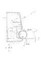
- FIG. 1 It is a perspective view which shows a chemical
- FIG. 1 It is the enlarged front view which expanded a part of front view of the main-body part of the syringe pump shown in FIG. It is sectional drawing of the prefilled syringe and syringe pump shown in FIG. It is a perspective view which shows the prefilled syringe of other embodiment.
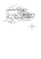
- FIG. 1 is a perspective view showing a chemical liquid administration system 1 including a prefilled syringe 200 and a syringe pump 100 as an embodiment.
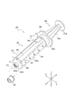
- FIG. 2 is a perspective view showing the prefilled syringe 200 shown in FIG.
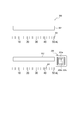
- FIG. 3 is a diagram showing an information description label 300 to which the prefilled syringe 200 shown in FIG. 2 is attached.
- FIG. 4 is a block diagram showing the RFID tag 206 attached to the prefilled syringe 200 and the reader 31 of the syringe pump 100.
- FIG. 5 is a diagram illustrating an example of a method for obtaining the prefilled syringe 200 to which the information description label 300 is attached.
- FIG. 1 is a perspective view showing a chemical liquid administration system 1 including a prefilled syringe 200 and a syringe pump 100 as an embodiment.
- FIG. 2 is a perspective view showing the prefilled syringe 200 shown in FIG.
- FIG. 3 is a
- FIG. 6 is an enlarged front view in which a part of the front view of the main body 3 of the syringe pump 100 shown in FIG. 1 is enlarged.
- FIG. 7 is a cross-sectional view of the prefilled syringe 200 and the syringe pump 100 shown in FIG. More specifically, FIG. 7 is a cross-sectional view showing a cross section orthogonal to the axial direction of the prefilled syringe 200 in a state where the prefilled syringe 200 is attached to the syringe pump 100.
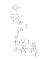
- FIG. 8 is a perspective view showing a prefilled syringe 600 of another embodiment.
- the drug solution administration system 1 of this embodiment includes a syringe pump 100 and a prefilled syringe 200 that can be attached to the syringe pump 100.
- a syringe pump 100 and a prefilled syringe 200 that can be attached to the syringe pump 100.
- each component will be described.
- the prefilled syringe 200 includes a chemical solution 201, a barrel 202, a cap 203, a gasket 204, a pusher 205, and an RFID tag 206.
- the drug solution 201 is, for example, an anticancer agent, an anesthetic agent, a chemotherapeutic agent, a blood transfusion, a nutrient, or the like.
- the chemical solution 201 is contained in the barrel 202.
- the chemical solution 201 is injected into a patient's body in a minute amount as will be described later.
- the barrel 202 includes a cylindrical body portion 202a, a nozzle portion 202b, and a flange portion 202c.
- the barrel 202a contains the chemical 201.
- the outer diameter D of the body 202a is 14 millimeters to 33 millimeters.
- the circumferential length of the outer peripheral surface of the body 202a is 2.0 to 7.0 times the maximum circumferential length Lc of the antenna of the RFID tag 206 described later.
- the nozzle part 202b is provided on the front end side of the body part 202a.
- a tip opening 202b1 is provided at the tip of the nozzle portion 202b.
- the chemical solution 201 is discharged from the tip opening 202b1.
- a tube 207 (indicated by a two-dot chain line in FIGS. 1 and 2) can be connected to the nozzle portion 202b.
- the flange portion 202c protrudes from the base end portion of the body portion 202a toward the outside in the radial direction B of the body portion 202a.
- the cap 203 can seal the tip opening 202b1 provided at the tip of the nozzle 202b.
- the cap 203 can be attached to the nozzle portion 202b, and FIG. 2 shows a state where the cap 203 is removed from the nozzle portion 202b and the tip opening 202b1 is opened.
- the gasket 204 slides on the inner peripheral surface of the trunk portion 202a.
- the gasket 204 of the present embodiment is a cylindrical body with a distal end closed and a proximal end opened.
- a chemical solution storage portion in which the chemical solution 201 is stored is formed in the barrel 202.
- the amount of the chemical solution stored is 5 ml to 50 ml.
- the amount (milliliter) of the chemical solution to be stored is associated with the outer diameter D (millimeter) of the prefilled syringe 200.
- the outer diameter D is 14 millimeters.
- the outer diameter D is 17 millimeters.
- the outer diameter D is 22 millimeters.
- the outer diameter D is 33 millimeters.
- the pusher 205 can be attached to the gasket 204.
- the presser 205 includes a presser main body 205a and a flange portion 205b.
- the distal end portion of the pusher main body 205 a can be fixed to the gasket 204 in a state where it is inserted from the proximal end side of the gasket 204.
- the presser body 205a and the gasket 204 can be fixed by, for example, screw joining.
- the presser body 205a is inserted into the body 202a and is movable in the axial direction A of the body 202a within the body 202a.
- the flange portion 205b is a proximal end portion of the presser 205 and protrudes outward in the radial direction B from the presser main body 205a.
- the RFID tag 206 is affixed to the outer surface of the information description label 300 described later. That is, the RFID tag 206 of this embodiment is affixed to the outer peripheral surface of the trunk portion 202a via the information description label 300. In another embodiment, the information description label 300 may be attached to the body 202a of the barrel 202 so as to cover the outer surface of the RFID tag 206.
- the RFID tag 206 is not attached over the entire region in the circumferential direction C of the trunk portion 202a, and is attached to only a part of the circumferential direction C.
- the maximum axial length La of the RFID tag 206 along the axial direction A of the barrel 202a of the barrel 202 is 8 to 25 millimeters.
- the base end of the RFID tag 206 is 15 millimeters to 40 millimeters (for example, 24.8 millimeters) in the distal direction from the distal end of the flange portion 202c of the barrel 202 toward the distal end side in the axial direction A of the barrel portion 202a. ) Are located apart.
- the RFID tag 206 is disposed on the proximal side of the gasket 204 in the axial direction A of the trunk portion 202a.
- the RFID tag 206 of the present embodiment is located on the proximal end side in the axial direction A of the trunk portion 202a with respect to the position of the distal end of the gasket 204 of the unused prefilled syringe 200. In other words, the RFID tag 206 of the present embodiment is not located further to the front end side than the front end of the gasket 204 in the axial direction A of the trunk portion 202a. As shown in FIG. 1, in this embodiment, the RFID tag 206 is attached to a portion where the clamp portion 5 of the syringe pump 100 clamps the outer peripheral surface of the prefilled syringe 200 (hereinafter referred to as a clamp contact portion 209). It is a base end side rather than the part currently made.
- the shape of the RFID tag 206 can be a rectangle with a circumferential length Lc of 18 millimeters and an axial length La of 18 millimeters in a state where the position is fixed with respect to the outer circumferential surface of the body 202a.
- a rectangle having a circumferential length Lc of 25 millimeters and an axial length La of 25 millimeters may be used.
- a rectangular shape having a circumferential length Lc of 12 millimeters and an axial length La of 9 millimeters may be used.
- the RFID tag 206 includes a communication antenna 206a, a memory 206b, and a control unit 206c.
- the antenna 206a of the RFID tag 206 is composed of an antenna wire wound in a rectangular shape.
- the area on the body 202a where the RFID tag 206 can be installed is limited, but compared to a configuration in which the antenna wire is wound in a circular shape by winding the antenna wire in a rectangular shape. It is easy to ensure a large loop area formed by the antenna wire.
- FIG.1 and FIG.7 when the prefilled syringe 200 is installed in the support part 4 of the syringe pump 100, the RFID tag 206 of the prefilled syringe 200 and the reader 31 of the syringe pump 100 are connected. Even if the positioning is not performed with high accuracy, the RFID tag 206 and the reader 31 can communicate with each other.
- the antenna 206a of the RFID tag 206 performs communication by wireless communication with a short reach, such as NFC (Near Field Communication).
- NFC Near Field Communication
- Lc is 9 to 25 millimeters.
- the outer edge of the antenna 206a may be a rectangle having a circumferential length of 15 millimeters and an axial length of 15 millimeters in the same state as described above.
- the outer edge of the antenna 206a may be a rectangle having a circumferential length of 25 millimeters and an axial length of 25 millimeters, for example, in the same state as described above.
- the control unit 206c of the RFID tag 206 can read data from the memory 206b and cause the antenna 206a to transmit the data.
- Wireless communication between the antenna 206a of the RFID tag 206 and the reader antenna 31a of the reader 31 of the syringe pump 100 has a short communicable distance (for example, within 35 mm). Therefore, when the RFID tag 206 of the prefilled syringe 200 is separated from the reader antenna 31a of the reader 31 by a predetermined distance or more, the reader antenna 31a of the reader 31 cannot communicate with the RFID tag 206 of the prefilled syringe 200.
- the memory 206b and the control unit 206c of the RFID tag 206 can be configured by an integrated circuit (IC chip) including a nonvolatile memory, for example.
- the antenna 206a of the RFID tag 206 receives electromagnetic waves transmitted from the reader antenna 31a of the reader 31 of the syringe pump 100.
- the operating power of the RFID tag 206 can be obtained from this electromagnetic wave.
- the control unit 206c reads the data in the memory 206b of the RFID tag 206, puts the data on an electromagnetic wave using the antenna 206a, and returns (transmits) the data to the reader antenna 31a of the reader 31.
- the reader antenna 31a of the reader 31 receives electromagnetic waves from the antenna 206a of the RFID tag 206.
- control part 31c of the syringe pump 100 acquires the data memorize
- the memory 206b of the RFID tag 206 for example, regarding the prefilled syringe 200, various data such as the name of the chemical 201, identification data for each individual, dimension data of the barrel 202, and dimension data of the stroke of the pusher 205 are stored. Yes.
- an information description label 300 is affixed to the outer peripheral surface of the barrel 202 a of the barrel 202.
- FIG. 3 shows an information description label 300 before being affixed to the outer peripheral surface of the trunk 202a.
- the information description label 300 is provided with two scales 301 so as to be along the axial direction A of the body 202a when being attached to the outer peripheral surface of the body 202a (see FIG. 2). More specifically, the notches of the two scales 301 of the present embodiment are arranged along the axial direction A of the trunk portion 202a in a state of being stuck on the outer peripheral surface of the trunk portion 202a.
- the scale 301 indicates the amount of the chemical solution 201 in the body 202a when the information description label 300 is affixed to the outer peripheral surface of the body 202a.
- the two scales 301 are symmetrical with respect to the central axis of the barrel 202a. Become.
- an RFID tag 206 is attached between the two scales 301 of the information description label 300.
- the RFID tag 206 is affixed to the outer surface of the information description label 300.
- the RFID tag 206 can be affixed to the inner surface of the information description label 300.
- a part of the RFID tag 206 overlaps a part of the two scales 301 in the longitudinal direction of the information description label 300 and is disposed at a position shifted in the short direction of the information description label 300. . That is, as shown in FIG. 2, when the information description label 300 is affixed to the outer peripheral surface of the barrel 202 a, a part of the RFID tag 206 is part of the scale 301 and the barrel 202 a of the barrel 202. It overlaps in the axial direction A and is disposed at a position shifted in the circumferential direction C of the barrel 202a of the barrel 202.
- the information description label 300 can be provided with an information area 302 in which the drug name or the amount of the drug solution is described.
- the roll-shaped mount 401 is pulled out.
- RFID tags 206 are installed on the mount 401 at regular intervals.
- various information is written in the RFID tag 206 as indicated by a region R1.
- the RFID tag 206 is removed from the mount 401, and the RFID tag 206 is attached to the outer surface of the information description label 300.
- the direction of the information description label 300 is appropriately set on the drum 402.
- the drum 403 it is inspected whether the information written in the RFID tag 206 is correct.
- the information description label 300 is affixed to the outer peripheral surface of the trunk portion 202 a of the prefilled syringe 200 using the drum 404.
- the syringe pump 100 is used in, for example, an intensive care unit. Moreover, the syringe pump 100 is used when a microinjection treatment of a liquid medicine such as an anticancer agent, an anesthetic agent, a chemotherapeutic agent, a blood transfusion, etc. is performed on the patient P with a high accuracy for a relatively long time. Can be used.
- a liquid medicine such as an anticancer agent, an anesthetic agent, a chemotherapeutic agent, a blood transfusion, etc.
- the syringe pump 100 of the present embodiment can be attached to and detached from a stand or the like, and can be used while being attached to the stand or the like.
- the syringe pump 100 is fixed so that the axial direction A of the body 202a of the prefilled syringe 200 in the mounted state is a horizontal direction.
- the syringe pump 100 includes a syringe pusher drive unit 2, a main body unit 3, a support unit 4, and a clamp unit 5.
- the syringe pusher drive unit 2 drives the pusher 205 of the prefilled syringe 200 in the distal direction toward the distal end side of the body 202a.
- the syringe pusher drive unit 2 of the present embodiment includes a pressing unit 2a and a flange fixing unit 2b.
- the pressing portion 2a is disposed on the proximal end side in the axial direction A with respect to the flange portion 205b of the presser 205 of the prefilled syringe 200 in the mounted state. And the surface of the base end side of the axial direction A of the flange part 205b can be pressed to the front end side of the axial direction A by moving the press part 2a to the front end side of the axial direction A. Thereby, the pusher 205 can be moved relatively to the distal end side in the axial direction A with respect to the barrel 202 of the prefilled syringe 200 in the mounted state.
- the flange fixing part 2b fixes the flange part 205b of the presser 205 to the pressing part 2a.
- the flange fixing portion 2b of the present embodiment is located on the distal end side in the axial direction A of the pressing portion 2a and is attached to the pressing portion 2a.
- the flange portion 205b of the pusher 205 is disposed between the pressing portion 2a and the flange fixing portion 2b. Accordingly, the pusher 205 can move in the axial direction A following the movement of the syringe pusher driving unit 2 in the axial direction A.
- FIG. 6 is an enlarged front view in which a part of the front view of the main body 3 of the syringe pump 100 is enlarged. More specifically, FIG. 6 shows an enlarged position of a support portion 4 to be described later that receives the prefilled syringe 200 in the main body portion 3.
- FIG. 6 for convenience of explanation, the prefilled syringe 200 that is properly received by the support portion 4 in a state where the flange portion 202 c is fitted in the flange receiving groove 7 (see FIG. 1) of the main body portion 3.
- a barrel 202 is illustrated.
- the main body 3 includes a reader 31 including a reader antenna 31a that receives a data set stored in the memory of the RFID tag 206 of the prefilled syringe 200, and a control unit 13 (see FIG. 1) that controls the syringe pusher drive unit 2.
- the reader 31 and the control unit 13 of this embodiment are arranged inside the main body unit 3.
- the control part 13 of the syringe pump 100 and the control part 31c mentioned above can be made into a separate component.
- the control unit 31c and the control unit 13 may be integrated into the same component.
- the reader antenna 31a of the reader 31 is composed of a reader antenna line. As shown in FIG.
- the outer edge of the reader antenna 31a composed of the reader antenna line is rectangular.
- a part of the reader antenna 31a of the reader 31 is a clamp part 5 of the syringe pump 100 to be described later in front view of the support part 4 of the syringe pump 100 (same as front view of the main body part 3 in FIG. 6). It deviates in the axial direction A from a first region 3a1, which will be described later, facing (see FIG. 1).
- the main body 3 is opposite to the syringe pusher drive unit 2 adjacent to the first region 3a1 in the first region 3a1 facing the clamp unit 5 and the axial direction A of the body 202a. And a second region 3a2 disposed on the side. At least a part of the reader antenna 31a of the reader 31 is arranged in the second region 3a2.
- the center line lca of the reader antenna 31a is orthogonal to the axial direction A of the barrel 202a of the barrel 202 in the front view of the support section 4 (same as the front view of the main body section 3 in the present embodiment). Is disposed in the second region 3a2.
- the center line lca of the reader antenna 31 a overlaps with the antenna 206 a of the RFID tag 206 in the front view of the support unit 4.
- the center line lca of the reader antenna 31a is along the axial direction A of the barrel 202a of the barrel 202 among the sides constituting the outer edge of the reader antenna 31a. It is a line passing through the center of each of the two sides.
- the center line lca of the reader antenna 31a is a line that bisects the loop area of the reader antenna 31a perpendicular to the axial direction A of the body 202a of the prefilled syringe 200.
- the center line may be a line that is orthogonal to the axial direction of the body portion of the prefilled syringe and bisects the loop area of the reader antenna.
- the reader antenna 31a of the reader 31 can transmit electromagnetic waves in a state where the prefilled syringe 200 is received by the support unit 4 described later.
- the RFID tag 206 attached to the prefilled syringe 200 transmits data in response to the electromagnetic wave.
- the reader antenna 31a of the reader 31 can receive the data.
- the main body unit 3 of the present embodiment includes a display unit 32 and an operation panel unit 33.
- the display unit 32 is an image display device capable of color display.
- the display unit 32 can be configured by a color liquid crystal display device, for example.
- the display unit 32 can display not only information notation in Japanese but also information in a plurality of foreign languages as necessary.
- the display part 32 of this embodiment is provided above the support part 4 mentioned later among the front surfaces of the syringe pump 100.
- the display unit 32 may include an input device such as a touch sensor and accept input from the user.
- the operation panel unit 33 is disposed on the upper side of the support unit 4 and on the right side of the display unit 32 in the front surface of the syringe pump 100.
- a power switch 33A On the operation panel 33, a power switch 33A, an operation indicator 33H, and an operation switch are arranged.
- FIG. 1 illustrates a fast-forward switch 33B, a start switch 33C, a stop switch 33D, a display changeover switch 33E, a return / mute switch 33F, and a confirmation switch 33G as examples of operation switches.
- various wirings for electrically connecting each member of the syringe pump 100, various mechanisms for executing commands from the control unit, external devices other than the RFID tag 206, and A communication unit capable of wireless or wired communication, a storage unit storing various data and various programs necessary for the operation of the syringe pump 100, and the like are arranged.
- the support portion 4 of the present embodiment is formed on the front surface of the main body portion 3. Moreover, the support part 4 of this embodiment supports the outer peripheral surface of the trunk
- the clamp portion 5 faces the support portion 4 formed on the main body portion 3, and clamps the body portion 202 a of the prefilled syringe 200 between the support portion 4.
- the clamp contact portion 209 (see FIG. 2), which is the portion where the clamp portion 5 clamps the prefilled syringe 200, of the outer peripheral surface of the body portion 202a is different from the portion where the RFID tag 206 is attached. The base end side of the portion where the RFID tag 206 is attached.
- the clamp part 5 is supported by the base 6 so as to be movable in the longitudinal direction of the base 6 (direction parallel to the central axis O2). Therefore, the opposing distance between the clamp part 5 and the support part 4 provided on the front side of the main body part 3 can be changed by moving the clamp part 5 in the longitudinal direction of the base 6. Thereby, it becomes possible to move the clamp part 5 between a clamping position and a non-clamping position.
- the clamping position of the clamp part 5 is a position where the trunk part 202a of the prefilled syringe 200 is sandwiched between the support part 4 as shown in FIG. Further, the non-clamping position of the clamp part 5 is a position where the body part 202a is not sandwiched between the support part 4 and the distance between the clamp part 5 and the support part 4.
- the clamp part 5 Since the clamp part 5 is always urged by the urging member such as a spring member in the longitudinal direction of the base 6 in the direction approaching the support part 4, the clamp part 5 is moved from the clamping position to the non-clamping position. Is moved against the urging force of the urging member.
- the urging member such as a spring member in the longitudinal direction of the base 6 in the direction approaching the support part 4
- the clamp portion 5 is supported by the base 6 so as to be movable not only in the longitudinal direction of the base 6 but also in the circumferential direction around the central axis O2 of the base 6.
- the position of the base 6 in the longitudinal direction can be fixed so that the clamp portion 5 does not move in the longitudinal direction of the base 6.
- the clamp part 5 is rotatable in the circumferential direction around the central axis O ⁇ b> 2 of the base 6 between a position facing the support part 4 and a position not facing the support part 4. This rotation operation cannot be performed when the clamp unit 5 is in the clamping position, and can be executed when the clamp unit 5 is in the non-clamping position.
- the prefilled syringe 200 can be easily placed on the receiving surface of the support part 4.
- the prefilled syringe 200 operates as follows in a mounted state (see FIG. 1) mounted on the syringe pump 100.
- the pusher 205 is pressed toward the distal end side in the axial direction A by the syringe pump 100.
- the gasket 204 connected to the pusher 205 slides in the body 202a of the barrel 202 toward the tip end side in the axial direction A.
- the chemical solution 201 in the barrel 202a is compressed.
- the chemical solution 201 is discharged through the nozzle portion 202b of the body portion 202a by this compression force.
- the tube 207 (see FIG. 1) is connected to the tip opening 202b1 of the nozzle portion 202b of the prefilled syringe 200.
- an indwelling needle 208 to be placed in the patient P is connected to the distal end of the tube 207. Therefore, the liquid medicine 201 in the body 202a can be fed into the patient P through the tube 207 and the indwelling needle 208.
- FIG. 8 shows a prefilled syringe 600 according to another embodiment.
- the length ratio in the longitudinal direction of the information description label 400 in FIG. 8 is smaller than the length ratio in the longitudinal direction of the information description label 300 in FIG.
- the longitudinal length ratio means the ratio of the total length of the information description label in the axial direction A to the total barrel length in the axial direction A of the trunk portion.
- the RFID tag 206 in FIG. 8 has the same configuration as that shown in FIG. However, the distance in the axial direction A (for example, 24.8 millimeters) between the flange portion 202c and the RFID tag 206 in FIG.
- the configuration of the prefilled syringe 600 is the same as the configuration of the prefilled syringe 200, and thus the description thereof is omitted.
- the outer diameter D of the barrel 202a of the barrel 202 is 14 mm to 33 mm.
- the maximum circumferential length Lc of the antenna of the RFID tag 206 along the circumferential direction C of the barrel 202a of the barrel 202 is 9 to 25 millimeters.
- the circumferential length of the outer peripheral surface of the trunk 202a is 2.0 to 7.0 times the maximum circumferential length of the antenna of the RFID tag 206.
- the position of the RFID tag 206 of the prefilled syringe 200 and the position of the reader of the syringe pump 100 are The RFID tag 206 and the reader 31 can communicate even if they are not aligned. Further, since the alignment of the prefilled syringe 200 or 600 is not necessary, the prefilled syringe 200 or 600 is slid between the RFID tag 206 fixed to the outer peripheral surface of the prefilled syringe 200 or 600 and the support portion 4 of the syringe pump 100. Damage to the RFID tag 206 of the syringe 200 or 600 can be suppressed.
- the outer peripheral surface of the prefilled syringe is a curved surface, so that the attached RFID tag may be deformed and the RFID tag may be peeled off.
- peeling of the RFID tag 206 attached to the outer peripheral surface of the prefilled syringe 200 or 600 can be suppressed.
- the maximum axial length La of the RFID tag 206 along the axial direction of the barrel 202a of the barrel 202 is 8 to 25 millimeters.
- the RFID tag 206 and the syringe pump 100 can be used when the cylindrical prefilled syringe 200 or 600 is installed on the support portion 4 of the syringe pump 100. Communication with the reader can be performed more reliably.
- the maximum axial length La of the RFID tag 206 is set to 25 millimeters or less, it is possible to prevent the RFID tag 206 from obscuring the scale 301, and the chemical solution 201 in which the RFID tag 206 is included in the trunk portion 202 a. Visibility can be prevented.
- the barrel 202 has a flange portion 202c protruding from the proximal end portion of the body portion 202a, and the body portion 202a is located near the flange portion 202c, with a pusher 205.
- the RFID tag 206 is disposed on the tip side of the clamp contact portion 209 in the axial direction A of the body portion 202a. . Thereby, it can prevent that the clamp part 5 of the syringe pump 100 contacts the RFID tag 206, and can prevent the RFID tag 206 from being damaged.
- the distance between the proximal end of the RFID tag 206 and the distal end of the flange portion 202c of the barrel 202 is 15 to 40 millimeters in the axial direction of the trunk portion 202a. .
- the clamp part 5 of the syringe pump 100 contacts the RFID tag 206 by setting the distance between the proximal end of the RFID tag 206 and the distal end of the flange part 202c of the barrel 202 in the axial direction of the body part 202a to 15 mm or more. This can prevent the RFID tag 206 from being damaged.
- the distance between the base end of the RFID tag 206 and the distal end of the flange portion 202c of the barrel 202 is set to 40 millimeters or less to prevent the scale 301 from becoming difficult to see, and The visibility of the chemical 201 contained in the part 202a can be ensured.
- the RFID tag 206 is disposed on the proximal end side with respect to the distal end of the gasket 204 in the axial direction A of the trunk portion 202a. Accordingly, it is possible to prevent the scale 301 from being difficult to see, and to ensure the visibility of the chemical solution 201 contained in the trunk portion 202a.
- the prefilled syringe 200 further includes an information description label 300 attached to the barrel 202a of the barrel 202.
- the RFID tag 206 can be configured to be affixed to the inner surface or the outer surface of the information description label 300. With these configurations, as shown in FIG. 5, when manufacturing the prefilled syringe 200, the information description label 300 and the RFID tag 206 can be attached to the barrel 202 at a time, thereby improving the production efficiency of the prefilled syringe 200. Can be made.
- the prefilled syringe 200 may include an information description label 300 attached to the barrel 202a of the barrel 202 so as to cover the outer surface of the RFID tag 206. Thereby, it is possible to prevent the RFID tag 206 fixed to the outer peripheral surface of the trunk portion 202a from being peeled off.
- the information description label 300 is provided with a scale 301 indicating the amount of the chemical 201 in the barrel 202a along the axial direction A of the barrel 202a of the barrel 202. At least a part of the RFID tag 206 overlaps at least a part of the scale 301 in the axial direction A of the barrel 202a of the barrel 202, and is shifted in a circumferential direction C of the barrel 202a of the barrel 202. Has been placed. Thereby, the scale 301 and the RFID tag 206 can be provided on the prefilled syringe 200 or 600 without increasing the axial length of the prefilled syringe 200 or 600.
- a plurality of scales 301 are provided, and the RFID tag 206 is disposed between at least two scales 301.
- the prefilled syringe 200 or 600 is installed in the syringe pump 100, at least one scale 301 can be exposed and visually recognized.
- At least two scales 301 are symmetric with respect to the central axis of the barrel 202a of the barrel 202. Thereby, it is possible to expose and visually recognize at least one scale 301 more reliably.
- the syringe pump 100 has the clamp portion 5 that faces the support portion 4 and clamps the body portion 202a of the prefilled syringe 200 or 600 between the support portion 4.
- the clamp contact unit 209 that is the portion of the outer peripheral surface of the body unit 202 a that the clamp unit 5 clamps. Is different from the part where the RFID tag 206 is attached. Thereby, it can prevent that the clamp part 5 of the syringe pump 100 contacts the RFID tag 206, and can prevent the RFID tag 206 from being damaged.
- the barrel 202 has a flange portion 202c protruding from the proximal end portion of the trunk portion 202a, and in the axial direction of the trunk portion 202a, the proximal end of the RFID tag 206,
- the distance from the front end of the flange portion 202c of the barrel 202 is 15 to 40 millimeters, and the clamp portion 5 abuts on the vicinity of the flange portion 202c of the body portion 202a, so that the prefilled syringe 200 or 600 is supported by the support portion 4. Clamp together.
- the distance between the proximal end of the RFID tag 206 and the distal end of the flange portion 202c of the barrel 202 is 15 millimeters or more, and the clamp portion 5 of the syringe pump 100 is connected to the flange of the barrel portion 202a.
- the distance between the proximal end of the RFID tag 206 and the distal end of the flange portion 202c of the barrel 202 is 40 millimeters or less to prevent the scale 301 from becoming difficult to see, Visibility of the chemical 201 contained in the body 202a can be ensured.
- the main body 3 of the syringe pump 100 is adjacent to the first region 3a1 in the first region 3a1 facing the clamp unit 5 and the axial direction A of the body 202a.
- the reader 31 has a second region 3a2 disposed on the opposite side of the syringe pusher drive unit 2, and the reader 31 is configured with a reader antenna line that communicates with the antenna 206a of the RFID tag 206. 31a and at least a part of the reader antenna 31a is disposed in the second region 3a2. That is, at least a part of the reader antenna 31a is disposed in the second region 3a2 that is not the first region 3a1 facing the clamp portion 5.
- the reader antenna 31a can reliably read the data set of the RFID tag 206.
- the prefilled syringe 200 or 600 is installed with respect to the syringe pump 100 so that at least a part of the RFID tag 206 faces the second region 3a2.
- the center line lca of the reader antenna 31a that is orthogonal to the axial direction of the body 202a of the barrel 202 in the front view of the support unit 4 is disposed in the second region 3a2.
- the center line lca of the reader antenna 31a overlaps with the antenna of the RFID tag 206 when the support unit 4 is viewed from the front.
- the position of the center line lca of the reader antenna 31a substantially coincides with the position where the magnetic flux density of the magnetic flux generated by the reader antenna 31a is highest. Therefore, by overlapping the center line lca of the reader antenna 31a with the antenna of the RFID tag 206, the reader 31 can read the data set of the RFID tag 206 more reliably.
- the syringe pump 100 has a clamp portion 5 that faces the support portion 4 and clamps the body portion 202a of the prefilled syringe 200 between the support portion 4 and the main body portion 3 of the syringe pump 100. Is disposed on the opposite side to the syringe pusher drive unit 2 adjacent to the first region 3a1 in the axial direction A of the body portion 202a and the first region 3a1 facing the clamp portion 5 of the body portion 202a.
- the reader 31 includes a reader antenna 31a composed of a reader antenna line that communicates with the antenna of the RFID tag 206, and at least a part of the reader antenna 31a is a second region. It is arranged at 3a2.
- the reader antenna 31a since at least a part of the reader antenna 31a is arranged in the second area 3a2 that is not the first area 3a1 facing the clamp unit 5, the reader antenna 31a reads the data set of the RFID tag 206. Can do. Moreover, when clamping the prefilled syringe 200 with the support part 4 and the clamp part 5, it can prevent that the RFID tag 206 contacts the clamp part 5 and is damaged. In addition, the prefilled syringe 200 or 600 is installed with respect to the syringe pump 100 so that at least a part of the RFID tag 206 faces the second region 3a2.
- the center line lca of the reader antenna 31a that is orthogonal to the trunk portion 202a of the barrel 202 in the front view of the support portion 4 is disposed in the second region 3a2.
- the reader 31 can read the data of the RFID tag 206 of the syringe pump 100 with certainty.
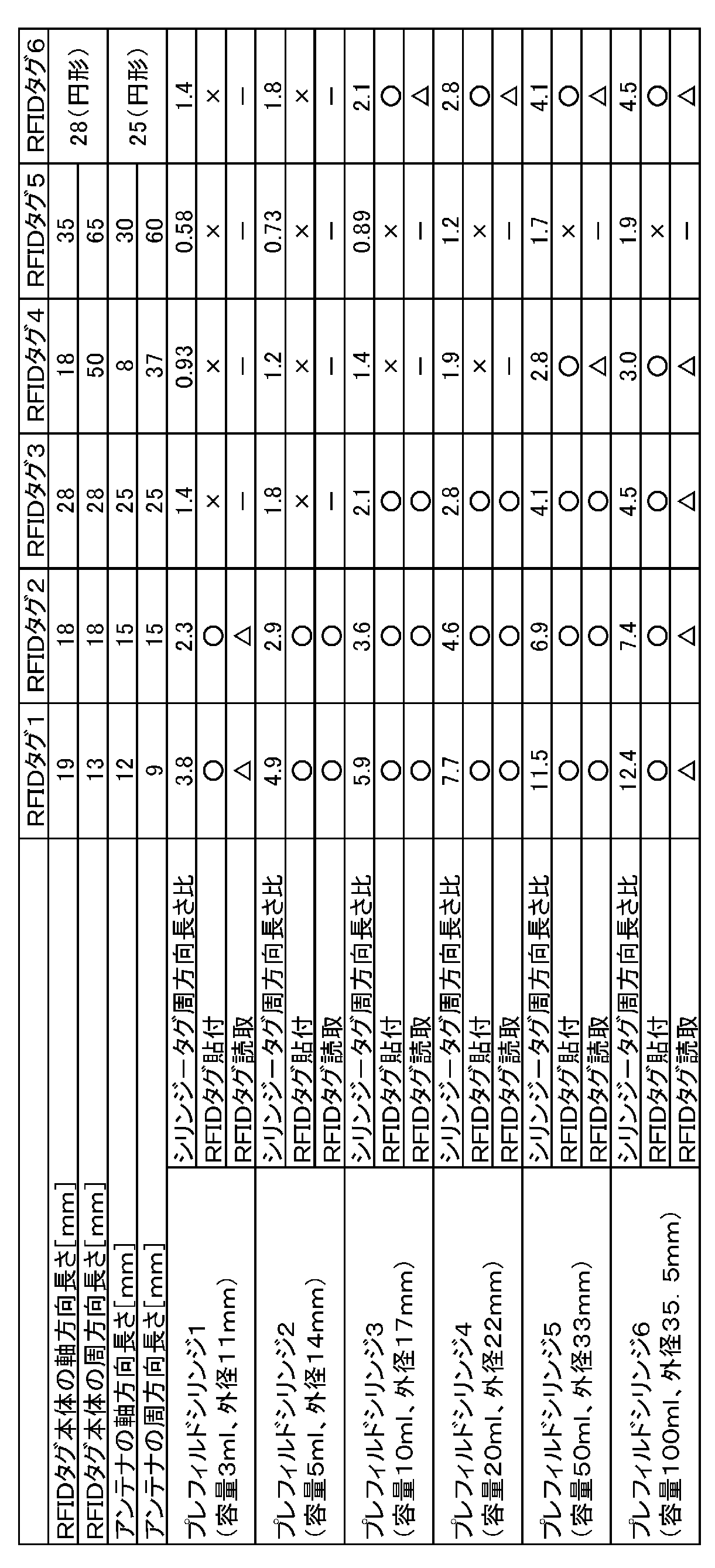
- prefilled syringes 1-6 with different outer diameters of barrel barrels were prototyped.
- the outer diameters of the barrels of the prefilled syringe 1-6 are 11 millimeters, 14 millimeters, 17 millimeters, 22 millimeters, 33 millimeters and 35.5 millimeters, respectively.
- the RFID tag 1-6 was affixed to the outer peripheral surface of the barrel portion of each barrel of the prefilled syringe 1-6, and then it was verified whether it was peeled off.
- the shape of the tag main body including the antenna, the memory, and the control unit of the RFID tag 1-5 and the outer edge of the antenna line are rectangular. Further, the shape of the tag body of the RFID tag 6 is a circle with an outer diameter of 28 mm, and the outer edge of the antenna line is a circle with an outer diameter of 25 mm.
- Table 1 shows the dimensions of the tag body of the RFID tag 1-6 and the dimensions of the antenna.
- Table 1 also shows a value obtained by dividing the circumferential length of the outer peripheral surface of the barrel portion of the barrel of the prefilled syringe by the maximum circumferential length of the RFID tag antenna (in Table 1, “the syringe-tag circumferential length ratio”). ”).
- the RFID tag 1-6 was affixed to the outer peripheral surface of the body portion of the prefilled syringe 1-6, and then it was verified whether or not it peeled off.
- “ ⁇ ” in Table 1 indicates a case where the RFID tag did not peel off.
- “X” indicates a case where the RFID tag is too large to be attached, or a case where the RFID tag is peeled off after being attached, in other words, a case where the RFID tag cannot be properly attached to the prefilled syringe. .
- Each prefilled syringe 1-6 was installed in the syringe pump 100 shown in FIG. 1 with the RFID tag 1-6 attached to the outer peripheral surface of the barrel of the outer peripheral surface of the barrel of the prefilled syringe 1-6.
- the attached RFID tag 1-6 was arranged at a position farthest from the reader 31 of the syringe pump 100, that is, with the RFID tag 206 facing the front side in FIG. In this state, it was verified a plurality of times whether the reader 31 of the syringe pump 100 can read the data of the RFID tag 1-6.
- “ ⁇ ” in Table 1 indicates that the RFID tag data could be read in all cases.
- “ ⁇ ” indicates that the RFID tag data could not be read.
- “ ⁇ ” indicates that the verification was not performed because the RFID tag could not be properly attached to the outer peripheral surface of the barrel portion of the barrel of the prefilled syringe.
- the antenna is constituted by an antenna wire wound in a rectangular shape, the outer diameter of the barrel body is set to 14 to 33 mm, and along the circumferential direction of the barrel body a.
- the maximum circumferential length Lc of the RFID tag antenna is 9 to 25 millimeters, and the circumferential length of the outer peripheral surface of the trunk is 2.0 to 7.0 times the maximum circumferential length of the RFID tag 206 antenna. It was found that the doubled prefilled syringe was easier for the syringe pump to acquire data and the attached RFID tag was harder to peel than any other prefilled syringe.
Landscapes
- Health & Medical Sciences (AREA)
- Vascular Medicine (AREA)
- Engineering & Computer Science (AREA)
- Anesthesiology (AREA)
- Biomedical Technology (AREA)
- Heart & Thoracic Surgery (AREA)
- Hematology (AREA)
- Life Sciences & Earth Sciences (AREA)
- Animal Behavior & Ethology (AREA)
- General Health & Medical Sciences (AREA)
- Public Health (AREA)
- Veterinary Medicine (AREA)
- Infusion, Injection, And Reservoir Apparatuses (AREA)
Abstract
Description
まず、プレフィルドシリンジ200の詳細について説明する。図2に示すように、プレフィルドシリンジ200は、薬液201と、バレル202と、キャップ203と、ガスケット204と、押子205と、RFIDタグ206と、を備えている。
次に、図1、図6及び図7を参照してシリンジポンプ100について説明する。
プレフィルドシリンジ1-6それぞれのバレルの胴部の外周面に、RFIDタグ1-6を貼付して、その後剥離しないか検証した。RFIDタグ1-5の、アンテナ、メモリ及び制御部を含むタグ本体の形状と、アンテナ線の外縁とは矩形である。また、RFIDタグ6のタグ本体の形状は外径28ミリメートルの円形であり、アンテナ線の外縁は外径25ミリメートルの円形である。RFIDタグ1-6のタグ本体の寸法と、アンテナの寸法とを表1に示す。また表1には、プレフィルドシリンジのバレルの胴部の外周面の周方向長さを、RFIDタグのアンテナの最大周方向長さで割った値(表1では「シリンジ-タグ周方向長さ比」と記載する)を示す。本実施例では、RFIDタグ1-6を、プレフィルドシリンジ1-6の胴部の外周面に貼付して、その後剥離しないか検証した。表1の「○」は、RFIDタグが剥離しなかった場合を示す。「×」は、RFIDタグのサイズが大きくて貼付できなかった場合や、RFIDタグを貼付した後に剥離した場合等であり、言い換えれば、RFIDタグをプレフィルドシリンジに適切に貼付できなかった場合を示す。
RFIDタグ1-6をプレフィルドシリンジ1-6のバレルの外周面の胴部の外周面に貼付した状態で、プレフィルドシリンジ1-6それぞれを図1に示すシリンジポンプ100に設置した。ここで、貼付されたRFIDタグ1-6は、シリンジポンプ100のリーダ31から最も離れた位置に、すなわち図1においてRFIDタグ206が手前側を向くように配置した。このような状態で、シリンジポンプ100のリーダ31が、RFIDタグ1-6のデータを読み取ることができるかを、複数回検証した。表1の「○」は全ての場合でRFIDタグのデータを読み取ることができたことを示す。「△」はRFIDタグのデータを読み取ることができない場合があったことを示す。さらに「-」は、プレフィルドシリンジのバレルの胴部の外周面にRFIDタグを適切に貼付できなかったため、本検証を行わなかったことを示す。
200,600:プレフィルドシリンジ
201:薬液
202:バレル
202a:胴部
202b:ノズル部
202b1:先端開口部
202c:フランジ部
203:キャップ
204:ガスケット
205:押子
205a:押子本体
205b:フランジ部
206:RFIDタグ
206a:アンテナ
206b:メモリ
206c:制御部
207:チューブ
208:留置針
209:クランプ当接部
100:シリンジポンプ
13:制御部
2:シリンジ押子駆動部
2a:押圧部
2b:フランジ固定部
3:本体部
31:リーダ
31a:リーダアンテナ
31b:メモリ
31c:制御部
32:表示部
33:操作パネル部
33A:電源スイッチ
33B:早送りスイッチ
33C:開始スイッチ
33D:停止スイッチ
33E:表示切替スイッチ
33F:消音スイッチ
33G:確認スイッチ
33H:動作インジケータ
3a1:第1領域
3a2:第2領域
4:支持部
5:クランプ部
6:ベース
7:フランジ受け溝
300,400:情報記載ラベル
301:目盛
302:情報領域
A:胴部の軸方向
B:胴部の径方向
C:胴部の周方向
D:胴部の外径
La:RFIDタグの軸方向長さ
Lc:RFIDタグの周方向長さ
O2:中心軸線
P:患者
lca:中心線
Claims (17)
- 薬液と、
前記薬液を内包する筒状の胴部と、前記胴部の先端側に設けられ、前記薬液を排出するノズル部と、を有するバレルと、
前記ノズル部の先端部に設けられた先端開口部を封止するキャップと、
前記胴部の内周面を摺動するガスケットと、
前記ガスケットに装着可能な押子と、
矩形状に巻き回されているアンテナ線により構成されている通信用のアンテナ及びメモリを有し、前記胴部の外周面に対して位置が固定されているRFIDタグと、を備え、
前記バレルの前記胴部の外径が14ミリメートル~33ミリメートルであり、
前記バレルの前記胴部の周方向に沿う、前記RFIDタグの前記アンテナの最大周方向長さが9ミリメートル~25ミリメートルであり、
前記バレルの前記胴部の外周面の周方向長さが、前記RFIDタグの前記アンテナの前記最大周方向長さの2.0倍~7.0倍である、プレフィルドシリンジ。 - 前記バレルの前記胴部の軸方向に沿う、前記RFIDタグの最大軸方向長さは、8ミリメートル~25ミリメートルである、請求項1に記載のプレフィルドシリンジ。
- 前記バレルは、前記胴部の基端部から突出するフランジ部を有し、
前記胴部は、前記フランジ部の近傍に、前記押子を駆動するシリンジポンプのクランプ部が当接するクランプ当接部を有し、
前記RFIDタグは、前記胴部の軸方向において、前記クランプ当接部よりも先端側に配置された、請求項1又は2に記載のプレフィルドシリンジ。 - 前記胴部の軸方向において、前記RFIDタグの基端と、前記バレルの前記フランジ部の先端との距離が、15ミリメートル~40ミリメートルである、請求項3に記載のプレフィルドシリンジ。
- 前記RFIDタグが、前記胴部の軸方向において、前記ガスケットの先端よりも基端側に配置された、請求項1乃至4のいずれか1つに記載のプレフィルドシリンジ。
- 前記バレルの前記胴部に貼付された情報記載ラベルを更に備え、
前記RFIDタグは、前記情報記載ラベルの内面又は外面に貼付されている、請求項1乃至5のいずれか1つに記載のプレフィルドシリンジ。 - 前記RFIDタグの外面を覆うように前記バレルの前記胴部に貼付された情報記載ラベルを更に備える、請求項1乃至5のいずれか1つに記載のプレフィルドシリンジ。
- 前記情報記載ラベルには、前記胴部の前記薬液の量を示す目盛が、前記バレルの前記胴部の軸方向に沿って設けられており、
前記RFIDタグの少なくとも一部は、前記目盛の少なくとも一部と、前記バレルの前記胴部の軸方向において重複し、かつ前記バレルの前記胴部の周方向にずれた位置に配置されている、請求項6又は7に記載のプレフィルドシリンジ。 - 前記目盛が複数設けられ、
前記RFIDタグは、少なくとも2つの前記目盛の間に配置されている、請求項8に記載のプレフィルドシリンジ。 - 前記少なくとも2つの目盛は、前記バレルの前記胴部の中心軸に対して対称である、請求項9に記載のプレフィルドシリンジ。
- シリンジポンプと、前記シリンジポンプに設置されるプレフィルドシリンジとを有する薬液投与システムであり、
前記プレフィルドシリンジは、
薬液と、
前記薬液を内包する筒状の胴部と、前記胴部の先端側に設けられ、前記薬液を排出するノズル部と、を有するバレルと、
前記ノズル部の先端部に設けられた先端開口部を封止するキャップと、
前記胴部の内周面を摺動するガスケットと、
前記ガスケットに装着可能な押子と、
矩形状に巻き回されているアンテナ線により構成されている通信用のアンテナ及びメモリを有し、前記胴部の外周面に対して位置が固定されているRFIDタグと、
を備えるプレフィルドシリンジであって、
前記バレルの前記胴部の外径が14ミリメートル~33ミリメートルであり、
前記バレルの前記胴部の周方向に沿う、前記RFIDタグの前記アンテナの最大周方向長さが9ミリメートル~25ミリメートルであり、
前記バレルの前記胴部の外周面の周方向長さが、前記RFIDタグの前記アンテナの前記最大周方向長さの2.0倍~7.0倍であり、
前記シリンジポンプは、
前記プレフィルドシリンジの前記押子を、前記胴部の先端側に向かう先端方向に駆動するシリンジ押子駆動部と、
前記プレフィルドシリンジの前記RFIDタグの前記メモリに記憶されたデータセットを読み取るリーダと前記シリンジ押子駆動部を制御する制御部とを備える本体部と、
前記プレフィルドシリンジの前記胴部の前記外周面を、前記胴部の軸に対して垂直な方向から支持する支持部と、
前記支持部と対向し、前記支持部との間で前記胴部をクランプするクランプ部と、を有する、薬液投与システム。 - 前記クランプ部が前記プレフィルドシリンジを前記支持部と前記クランプ部との間でクランプする際に、前記胴部の前記外周面のうち前記クランプ部がクランプする部分は、前記RFIDタグが貼付されている部分とは異なる、請求項11に記載の薬液投与システム。
- 前記バレルは、前記胴部の基端部から突出するフランジ部を有し、
前記胴部の軸方向において、前記RFIDタグの基端と、前記バレルの前記フランジ部の先端との距離が、15ミリメートル~40ミリメートルであり、
前記クランプ部は、前記胴部の前記フランジ部の近傍に当接することで、前記プレフィルドシリンジを前記支持部とともにクランプする、請求項12に記載の薬液投与システム。 - 前記シリンジポンプの前記本体部は、前記クランプ部と対向する第1領域と、前記胴部の軸方向において、前記第1領域に隣接して、前記シリンジ押子駆動部に対して反対側に配置された第2領域とを有し、
前記リーダは、前記RFIDタグのアンテナと通信する、リーダアンテナ線から形成されるリーダアンテナを含み、
前記リーダアンテナの少なくとも一部が、前記第2領域に配置されている、請求項13に記載の薬液投与システム。 - 前記支持部の正面視において前記バレルの前記胴部の軸方向と直交する、前記リーダアンテナの中心線が、前記第2領域に配置されているとともに、
前記支持部の正面視において、前記リーダアンテナの中心線が、前記RFIDタグの前記アンテナと重なる、請求項14に記載の薬液投与システム。 - プレフィルドシリンジが設置されるシリンジポンプであり、
前記プレフィルドシリンジは、
薬液と、
前記薬液を内包する筒状の胴部と、前記胴部の先端側に設けられ、前記薬液を排出するノズル部と、を有するバレルと、
前記ノズル部の先端部に設けられた先端開口部を封止するキャップと、
前記胴部の内周面を摺動するガスケットと、
前記ガスケットに装着可能な押子と、
矩形状に巻き回されているアンテナ線により構成されている通信用のアンテナ及びメモリを有し、前記胴部の外周面に対して位置が固定されているRFIDタグと、
を備えるプレフィルドシリンジであって、
前記シリンジポンプは、
前記プレフィルドシリンジの前記押子を、前記胴部の先端側に向かう先端方向に駆動するシリンジ押子駆動部と、
前記プレフィルドシリンジの前記RFIDタグの前記メモリに記憶されたデータセットを読み取るリーダと前記シリンジ押子駆動部を制御する制御部とを備える本体部と、
前記プレフィルドシリンジの前記胴部の前記外周面を、前記胴部の軸に対して垂直な方向から支持する支持部と、
前記支持部と対向し、前記支持部との間で前記プレフィルドシリンジの前記胴部をクランプするクランプ部と、を有し、
前記シリンジポンプの前記本体部は、クランプ部と対向する第1領域と、前記胴部の軸方向において、前記第1領域に隣接して、前記シリンジ押子駆動部に対して反対側に配置された第2領域とを有し、
前記リーダは、前記RFIDタグの前記アンテナと通信する、リーダアンテナ線から構成されているリーダアンテナを含み、
前記リーダアンテナの少なくとも一部が、前記第2領域に配置されている、シリンジポンプ。 - 前記支持部の正面視において前記バレルの前記胴部の軸方向と直交する、前記リーダアンテナの中心線が、前記第2領域に配置されている、請求項16に記載のシリンジポンプ。
Priority Applications (4)
| Application Number | Priority Date | Filing Date | Title |
|---|---|---|---|
| JP2020509244A JP7412330B2 (ja) | 2018-03-29 | 2019-03-27 | シリンジポンプ |
| EP19777032.4A EP3777924A4 (en) | 2018-03-29 | 2019-03-27 | PRE-FILLED SYRINGE, LIQUID MEDICATION DELIVERY SYSTEM AND SYRINGE PUMP |
| US17/037,212 US20210008275A1 (en) | 2018-03-29 | 2020-09-29 | Prefilled syringe, liquid medicine administration system, and syringe pump |
| JP2023219782A JP2024023933A (ja) | 2018-03-29 | 2023-12-26 | プレフィルドシリンジ |
Applications Claiming Priority (2)
| Application Number | Priority Date | Filing Date | Title |
|---|---|---|---|
| JP2018-066113 | 2018-03-29 | ||
| JP2018066113 | 2018-03-29 |
Related Child Applications (1)
| Application Number | Title | Priority Date | Filing Date |
|---|---|---|---|
| US17/037,212 Continuation US20210008275A1 (en) | 2018-03-29 | 2020-09-29 | Prefilled syringe, liquid medicine administration system, and syringe pump |
Publications (1)
| Publication Number | Publication Date |
|---|---|
| WO2019189449A1 true WO2019189449A1 (ja) | 2019-10-03 |
Family
ID=68059200
Family Applications (1)
| Application Number | Title | Priority Date | Filing Date |
|---|---|---|---|
| PCT/JP2019/013334 WO2019189449A1 (ja) | 2018-03-29 | 2019-03-27 | プレフィルドシリンジ、薬液投与システム及びシリンジポンプ |
Country Status (4)
| Country | Link |
|---|---|
| US (1) | US20210008275A1 (ja) |
| EP (1) | EP3777924A4 (ja) |
| JP (2) | JP7412330B2 (ja) |
| WO (1) | WO2019189449A1 (ja) |
Cited By (1)
| Publication number | Priority date | Publication date | Assignee | Title |
|---|---|---|---|---|
| EP4142836A4 (en) * | 2020-11-02 | 2023-09-27 | Becton, Dickinson and Company | RADIO FREQUENCY IDENTIFICATION (RFID) INLAYS FOR USE WITH MEDICAL INJECTION DEVICES |
Families Citing this family (3)
| Publication number | Priority date | Publication date | Assignee | Title |
|---|---|---|---|---|
| EP3971776A1 (en) * | 2020-09-18 | 2022-03-23 | Becton Dickinson France | Medical container comprising an rfid tag for remote identification |
| USD979764S1 (en) * | 2021-01-15 | 2023-02-28 | B. Braun Melsungen Ag | Rack for syringe pump and/or infusion pump |
| USD1006989S1 (en) * | 2021-06-28 | 2023-12-05 | Albert A. Mikhail | Medical syringe |
Citations (7)
| Publication number | Priority date | Publication date | Assignee | Title |
|---|---|---|---|---|
| JP2004092671A (ja) * | 2002-08-29 | 2004-03-25 | Terumo Corp | シリンジ用ガスケット、ガスケット付プランジャー、シリンジ及びプレフィルドシリンジ |
| WO2006006643A1 (ja) * | 2004-07-14 | 2006-01-19 | Nemoto Kyorindo Co., Ltd. | 薬液注入システム |
| WO2007032341A1 (ja) * | 2005-09-12 | 2007-03-22 | Nemoto Kyorindo Co., Ltd. | 薬液注入システム |
| JP2008535569A (ja) * | 2005-04-06 | 2008-09-04 | マリンクロッド・インコーポレイテッド | 医療流体及びその容器に関する情報を管理するシステム及び方法 |
| JP2015217176A (ja) | 2014-05-19 | 2015-12-07 | 株式会社根本杏林堂 | 薬液注入装置 |
| WO2017038483A1 (ja) * | 2015-09-04 | 2017-03-09 | テルモ株式会社 | シリンジポンプ |
| JP2017531459A (ja) * | 2014-08-28 | 2017-10-26 | ユニトラクト シリンジ プロプライエタリイ リミテッドUnitract Syringe Pty Ltd | 薬剤送達デバイス用センサシステム |
Family Cites Families (14)
| Publication number | Priority date | Publication date | Assignee | Title |
|---|---|---|---|---|
| US7501954B1 (en) * | 2000-10-11 | 2009-03-10 | Avante International Technology, Inc. | Dual circuit RF identification tags |
| JP4347692B2 (ja) * | 2001-09-12 | 2009-10-21 | テルモ株式会社 | 薬剤容器とこれを用いた薬剤注入装置 |
| WO2006054651A1 (ja) * | 2004-11-18 | 2006-05-26 | Nemoto Kyorindo Co., Ltd. | 薬液注入システム |
| US8753308B2 (en) * | 2006-01-06 | 2014-06-17 | Acelrx Pharmaceuticals, Inc. | Methods for administering small volume oral transmucosal dosage forms using a dispensing device |
| WO2007116863A1 (ja) * | 2006-04-05 | 2007-10-18 | Nemoto Kyorindo Co., Ltd. | 薬液注入システム |
| US9295790B2 (en) * | 2006-05-05 | 2016-03-29 | Retractable Technologies, Inc. | Syringe with recessed nose and protective guard for use with frontal attachments |
| US9326742B2 (en) * | 2007-01-01 | 2016-05-03 | Bayer Healthcare Llc | Systems for integrated radiopharmaceutical generation, preparation, transportation and administration |
| US20080243088A1 (en) * | 2007-03-28 | 2008-10-02 | Docusys, Inc. | Radio frequency identification drug delivery device and monitoring system |
| US20080306443A1 (en) * | 2007-06-06 | 2008-12-11 | Mallinckrodt Inc. | Medical Fluid Injector Having Wireless Pressure Monitoring Feature |
| EP2337595B1 (en) * | 2008-08-19 | 2012-07-04 | Mallinckrodt LLC | Power injector syringe clamp assembly with rfid antenna |
| EP2345441B1 (en) * | 2008-10-06 | 2018-11-21 | Terumo Kabushiki Kaisha | Syringe pump |
| US20170165427A1 (en) * | 2014-07-14 | 2017-06-15 | Bayer Healthcare Llc | Syringe and fluid injection system with an orientation independent identification code |
| WO2017125859A2 (en) * | 2016-01-20 | 2017-07-27 | Appelbaum Nicholas | Generating a dosing aid label for a syringe |
| US12064605B2 (en) * | 2018-03-29 | 2024-08-20 | Retractable Technologies, Inc. | Syringe with flat indicia display surface |
-
2019
- 2019-03-27 WO PCT/JP2019/013334 patent/WO2019189449A1/ja active Application Filing
- 2019-03-27 JP JP2020509244A patent/JP7412330B2/ja active Active
- 2019-03-27 EP EP19777032.4A patent/EP3777924A4/en active Pending
-
2020
- 2020-09-29 US US17/037,212 patent/US20210008275A1/en active Pending
-
2023
- 2023-12-26 JP JP2023219782A patent/JP2024023933A/ja active Pending
Patent Citations (7)
| Publication number | Priority date | Publication date | Assignee | Title |
|---|---|---|---|---|
| JP2004092671A (ja) * | 2002-08-29 | 2004-03-25 | Terumo Corp | シリンジ用ガスケット、ガスケット付プランジャー、シリンジ及びプレフィルドシリンジ |
| WO2006006643A1 (ja) * | 2004-07-14 | 2006-01-19 | Nemoto Kyorindo Co., Ltd. | 薬液注入システム |
| JP2008535569A (ja) * | 2005-04-06 | 2008-09-04 | マリンクロッド・インコーポレイテッド | 医療流体及びその容器に関する情報を管理するシステム及び方法 |
| WO2007032341A1 (ja) * | 2005-09-12 | 2007-03-22 | Nemoto Kyorindo Co., Ltd. | 薬液注入システム |
| JP2015217176A (ja) | 2014-05-19 | 2015-12-07 | 株式会社根本杏林堂 | 薬液注入装置 |
| JP2017531459A (ja) * | 2014-08-28 | 2017-10-26 | ユニトラクト シリンジ プロプライエタリイ リミテッドUnitract Syringe Pty Ltd | 薬剤送達デバイス用センサシステム |
| WO2017038483A1 (ja) * | 2015-09-04 | 2017-03-09 | テルモ株式会社 | シリンジポンプ |
Non-Patent Citations (1)
| Title |
|---|
| See also references of EP3777924A4 |
Cited By (2)
| Publication number | Priority date | Publication date | Assignee | Title |
|---|---|---|---|---|
| EP4142836A4 (en) * | 2020-11-02 | 2023-09-27 | Becton, Dickinson and Company | RADIO FREQUENCY IDENTIFICATION (RFID) INLAYS FOR USE WITH MEDICAL INJECTION DEVICES |
| US12067438B2 (en) | 2020-11-02 | 2024-08-20 | Becton, Dickinson And Company | Radio frequency identification (RFID) inlays for use with medical injection devices |
Also Published As
| Publication number | Publication date |
|---|---|
| JP2024023933A (ja) | 2024-02-21 |
| US20210008275A1 (en) | 2021-01-14 |
| EP3777924A4 (en) | 2022-05-04 |
| JP7412330B2 (ja) | 2024-01-12 |
| JPWO2019189449A1 (ja) | 2021-03-18 |
| EP3777924A1 (en) | 2021-02-17 |
Similar Documents
| Publication | Publication Date | Title |
|---|---|---|
| WO2019189449A1 (ja) | プレフィルドシリンジ、薬液投与システム及びシリンジポンプ | |
| US11730431B2 (en) | Injectable vascular access port with discernable markers for identification | |
| JP4769197B2 (ja) | 薬液注入システム | |
| JP5001158B2 (ja) | 薬液注入システム | |
| JP4925828B2 (ja) | 薬液注入システム | |
| JP2002011096A (ja) | シリンジ、シリンダホルダ、および薬液注入システム | |
| JP2017200617A5 (ja) | ||
| KR20220128323A (ko) | 약액 주입 장치 | |
| JPWO2007116864A1 (ja) | 薬液注入システム | |
| CN113164678B (zh) | 给药液装置 | |
| WO2019189451A1 (ja) | プレフィルドシリンジ | |
| WO2007114446A1 (ja) | 薬液注入システム | |
| WO2019187689A1 (ja) | シリンジポンプシステム及びシリンジポンプ | |
| JP7042280B2 (ja) | シリンジポンプ | |
| JP6947598B2 (ja) | シリンジポンプ | |
| JP4956219B2 (ja) | 薬液注入用具および薬液注入装置 | |
| JP2008200162A (ja) | 薬液注入用具および薬液注入装置 | |
| JP2019063253A (ja) | シリンジポンプ | |
| US20230256159A1 (en) | Drug delivery device cassette | |
| JP7183169B2 (ja) | 医療用ポンプ、医療用ポンプの制御方法、及び医療用ポンプシステム | |
| JP2024050282A (ja) | カニューレポート、クレードル装置及び薬液投与装置 | |
| JPS63164960A (ja) | 生体内流体注入装置 | |
| JP2011200430A (ja) | 血管外漏出検知装置及び輸液装置 |
Legal Events
| Date | Code | Title | Description |
|---|---|---|---|
| 121 | Ep: the epo has been informed by wipo that ep was designated in this application |
Ref document number: 19777032 Country of ref document: EP Kind code of ref document: A1 |
|
| ENP | Entry into the national phase |
Ref document number: 2020509244 Country of ref document: JP Kind code of ref document: A |
|
| NENP | Non-entry into the national phase |
Ref country code: DE |
|
| WWE | Wipo information: entry into national phase |
Ref document number: 2019777032 Country of ref document: EP |
|
| ENP | Entry into the national phase |
Ref document number: 2019777032 Country of ref document: EP Effective date: 20201029 |