WO2019189441A1 - 医療デバイス - Google Patents
医療デバイス Download PDFInfo
- Publication number
- WO2019189441A1 WO2019189441A1 PCT/JP2019/013317 JP2019013317W WO2019189441A1 WO 2019189441 A1 WO2019189441 A1 WO 2019189441A1 JP 2019013317 W JP2019013317 W JP 2019013317W WO 2019189441 A1 WO2019189441 A1 WO 2019189441A1
- Authority
- WO
- WIPO (PCT)
- Prior art keywords
- detection unit
- unit
- medical device
- needle
- puncture
- Prior art date
- Legal status (The legal status is an assumption and is not a legal conclusion. Google has not performed a legal analysis and makes no representation as to the accuracy of the status listed.)
- Ceased
Links
Images


Classifications
-
- A—HUMAN NECESSITIES
- A61—MEDICAL OR VETERINARY SCIENCE; HYGIENE
- A61B—DIAGNOSIS; SURGERY; IDENTIFICATION
- A61B5/00—Measuring for diagnostic purposes; Identification of persons
- A61B5/02—Detecting, measuring or recording for evaluating the cardiovascular system, e.g. pulse, heart rate, blood pressure or blood flow
- A61B5/021—Measuring pressure in heart or blood vessels
- A61B5/022—Measuring pressure in heart or blood vessels by applying pressure to close blood vessels, e.g. against the skin; Ophthalmodynamometers
-
- A—HUMAN NECESSITIES
- A61—MEDICAL OR VETERINARY SCIENCE; HYGIENE
- A61M—DEVICES FOR INTRODUCING MEDIA INTO, OR ONTO, THE BODY; DEVICES FOR TRANSDUCING BODY MEDIA OR FOR TAKING MEDIA FROM THE BODY; DEVICES FOR PRODUCING OR ENDING SLEEP OR STUPOR
- A61M5/00—Devices for bringing media into the body in a subcutaneous, intra-vascular or intramuscular way; Accessories therefor, e.g. filling or cleaning devices, arm-rests
- A61M5/42—Devices for bringing media into the body in a subcutaneous, intra-vascular or intramuscular way; Accessories therefor, e.g. filling or cleaning devices, arm-rests having means for desensitising skin, for protruding skin to facilitate piercing, or for locating point where body is to be pierced
Definitions
- the present invention relates to a medical device.
- various medical elongated bodies for example, medical devices such as introducers
- a procedure for treating or treating a lesion site has been performed.
- an operator or the like performs hemostasis of the puncture site when the medical long body is removed from the puncture site.
- a hemostatic device used for hemostasis of the puncture site a band for wrapping around a limb such as an arm, a fixing means for fixing the band in a state of being wrapped around the limb, and a fluid connected to the band And a pressing portion that expands and presses the puncture site is known (see Patent Document 1).
- the radial artery that runs on the human arm is connected to the palmar artery that bypasses the hand side (for example, the radial artery around the snuff box or the distal radial artery that runs on the fingertip side from the snuff box). Therefore, for example, an operator or the like can insert a medical long body into the radial artery running on the arm side by forming a puncture site in the palmar artery.
- the puncture site is formed on the hand instead of the arm or wrist, the patient can move the arm while hemostasis is being performed (while the compression force is being applied to the puncture site). Since it becomes possible, the degree of freedom of movement of the body is increased, and QOL (quality of life) is improved.
- an object of the present invention is to provide a medical device that enables accurate positioning of the puncture position with respect to the palmar artery.
- a medical device that achieves the above-described object is provided with a first detection unit that detects a blood pressure of a subject from the skin surface layer side, and is spaced apart from the first detection unit by a predetermined distance, A second detection unit that detects the blood pressure of the subject from the skin surface layer side at a position different from the first detection unit; a detection result of the first detection unit; and a detection result of the second detection unit.
- An output unit for outputting, and a guide unit for guiding a needle tip of a puncture device to be punctured by the subject between the first detection unit and the second detection unit.
- the detection result of the first detection unit and the detection result of the second detection unit are output to the output unit. Further, when the palm artery is punctured, the puncture site can be formed at an accurate position by guiding the needle tip of the puncture device to a desired position by the guide portion.
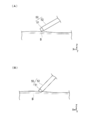
- FIG. 5A and FIG. 5B are diagrams showing a state when a puncture site is formed by a puncture device.
- 1 is a cross-sectional view perpendicular to an axis showing a needle assembly according to an embodiment of the present invention. It is a figure which shows the puncture site
- a direction in which the support bases 41 and 42 included in the medical device 100 are arranged is referred to as a “length direction X”.
- the width direction of each output part 30A, 30B with which the medical device 100 is provided and the guide part 40 is described as "width direction Y”.
- a height direction orthogonal to the length direction X and the width direction Y is referred to as a “height direction Z”.
- (First embodiment) 1 to 7 are views for explaining a medical device 100 according to an embodiment of the present invention.
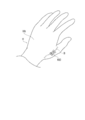
- the medical device 100 travels on the fingertip side of the radial artery (for example, the radial artery around the snuff box or the snuff box) of the palm artery (deep palm artery) B that travels on the back Hb of the hand H of the subject (patient).
- a medical long body such as a catheter or an introducer is introduced from a distal radial artery or the like, it is used to form a puncture site t1 at a desired position on the back of the hand Hb.
- the position at which the puncture site t1 is formed is not particularly limited as long as the medical elongated body can be inserted into the palmar artery B running on the hand H, and any of the left hand, the right hand, the back side of the hand, the palm side, etc. It may be the site of.
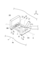
- the medical device 100 includes a first detection unit 10, a second detection unit 20, a first output unit 30A, a second output unit 30B, a guide unit 40, and A needle assembly (corresponding to a “puncture device”) 50 is included.
- the first detection unit 10 and the second detection unit 20 detect the blood pressure of the subject from the surface layer side of the skin.
- the first detection unit 10 includes a pressure sensor 11 and a support 12.
- the pressure sensor 11 is configured to detect the blood pressure of the subject at a constant interval in the width direction Y of the support bases 41 and 42 of the guide unit 40.
- the support 12 is disposed adjacent to the pressure sensor 11 and is disposed farther from the subject's skin than the pressure sensor 11.
- the pressure sensor 11 can be configured by, for example, a known sheet-type pressure sensitive sensor.
- the support 12 is made of a flexible material, so that the first detection unit 10 can be flexibly deformed in accordance with the wearing site of the subject.
- Examples of the material of the support 12 include polyurethane and urethane elastomer.
- the second detection unit 20 is disposed at a predetermined distance from the first detection unit 10 in the length direction X, and the blood pressure of the subject is measured from the skin surface side at a position different from the first detection unit 10. To detect.
- the 2nd detection part 20 is provided with the pressure sensor 21 and the support body 22 as shown in FIG.
- the pressure sensor 21 is the same as the pressure sensor 11 of the first detection unit 10, and the support 22 is the same as the support 12 of the first detection unit 10, and thus description thereof is omitted.
- the first output unit 30 ⁇ / b> A is disposed on the support base 41.
- the first output unit 30A outputs the detection result of the first detection unit 10.
- the second output unit 30B is disposed on the support base 42.
- the second output unit 30B outputs the detection result of the second detection unit 20. Since the first output unit 30A and the second output unit 30B have substantially the same configuration, the first output unit 30A will be described, and the description of the second output unit 30B will be omitted as appropriate.
- the first output unit 30A includes a display unit 31 and an instruction unit 32.
- the display unit 31 is configured to visually display the pressure distribution in the direction intersecting the blood vessel traveling as a detection result of the first detection unit 10 on the support base 41. As shown in FIG. 4, the display unit 31 displays the detected pressure value detected by the pressure sensor 11 of the first detection unit 10 as an example with a histogram having no numerical value.
- the display unit 31 is configured to display a pressure detection result at every predetermined interval in the width direction Y of the support base 41 constituting the guide unit 40. With this configuration, it is possible to grasp which position in the width direction Y of the support base 41 the palm artery B is close to.
- the display unit 31 is provided on the support base 42 in the same manner as the support base 41. In addition, you may comprise the display part 31 so that the detected pressure may be displayed with a numerical value, a symbol, a character, these combinations, etc.
- the instruction unit 32 is configured to display the center position of the display unit 31 in the width direction Y of the support base 41. As shown in FIG. 4, the instruction unit 32 is displayed by a substantially triangular mark pointing upward at the lower portion of the display unit 31 in the present embodiment.
- the second output unit 30B displays the pressure detection result at predetermined intervals in the width direction Y of the support base 42.
- the instruction unit 32 of the second output unit 30 ⁇ / b> B displays the center position of the display unit 31 in the width direction Y of the support base 41.
- the guide unit 40 is between the first detection unit 10 and the second detection unit 20 (substantially the central position between the first detection unit 10 and the second detection unit 20 in the length direction X).
- the needle tip of the needle assembly 50 to be punctured by the subject is guided.
- the guide unit 40 includes support bases 41 and 42 and rod-shaped members 43 and 44.
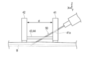
- the support base 41 is attached to the upper part of the first detection unit 10 in the height direction Z. As shown in FIG. 2, the support base 41 is configured to include a concave guide groove 41 a on which the needle tip of the needle assembly 50 is placed. As shown in FIG. 3, the medical device 100 is aligned with the subject by the first detection unit 10, the second detection unit 20, the first output unit 30 ⁇ / b> A, and the second output unit 30 ⁇ / b> B. Further, by placing the needle portion of the needle assembly 50 in the guide groove 41a, the puncture can be performed while the palm artery B to be punctured is observed.
- the needle portion of the needle assembly 50 is placed in the guide groove 41a so as to be inclined, for example, by 30 degrees from the horizontal plane, and the needle tip has an angle suitable for puncture. be able to. Further, the puncture can be performed so as to follow the traveling direction of the palm artery B and aiming at the approximate center of the palm artery B.
- the support base 42 is attached to the upper part of the second detection unit 20.
- the support base 42 is arranged at an interval in the length direction X from the support base 41, thereby guiding the tip of the needle portion of the needle assembly 50 between the support bases 41 and 42.
- the distance d between the support base 41 and the support base 42 is, for example, a guide groove 41a formed so as to insert the needle assembly 50 at about 30 degrees, and puncture at a depth of about 2 mm from the body surface. When doing so, it can be set to 5 mm to 10 mm.
- the rod-shaped members 43 and 44 are configured to connect support bases 41 and 42 that are arranged at intervals in the length direction X.
- the rod-shaped members 43 and 44 leave a predetermined space in the width direction Y of the support bases 41 and 42 so that the needle tip of the needle assembly 50 can be guided between the support base 41 and the support base 42. Arranged.
- the needle assembly 50 includes an inner needle 51 and an outer tube 52.
- the tips of the inner needle 51 and the outer tube 52 are formed in a substantially rectangular shape as shown in FIG.
- the wound (the shape in plan view of the puncture site t1) at the time of puncture can be formed in a shape extending along the running direction of the palm artery B as shown in FIG. Since blood vessels generally have elasticity, even when a wound is formed along the running direction of the palmar artery B, the medical elongated body having a substantially circular cross section is allowed to pass smoothly. Can do.
- the wound formed by the inner needle 51 can be expected to act in a direction that naturally closes after the elongate medical body is removed.
- part t1 as mentioned above does not push a wound out forcibly, it can make a wound easy to close.
- recesses 53 a and 53 b are formed on the outer surface of the inner needle 51 so as to form a blood flow path between the outer needle 52 and the outer needle 52.
- the recesses 53a and 53b are provided at two different positions in the height direction of the inner needle 51 (the vertical direction in FIG. 6).
- the operator confirms through which concave portion 53 and 53b the blood is flowing, whereby the needle assembly It can be grasped to what depth 50 has punctured the palm artery B.
- the risk of unintentional double wall puncture can be reduced, and the palmar artery B can be captured by single wall puncture (puncture of only the blood vessel wall on the near side from the body surface of the palmar artery B).
- outer surface of the inner needle 51 may be subjected to pear processing or embossing processing in order to prevent the inner needle 51 and the skin from adhering to each other.
- the surgeon places the medical device 100 in the vicinity of the palm arteries B of the hand H as shown in FIG. 1, displays the detection result of the first detection unit 10 on the first output unit 30A, and performs the second detection.
- the detection result of the unit 20 is displayed on the second output unit 30B.
- the surgeon adjusts the position of the medical device 100 so that the pressure distribution indicated by the first output unit 30A and the pressure distribution indicated by the second output unit 30B are substantially the same.
- the surgeon outputs the pressure distribution displayed on the first output unit 30A from which the detection result of the first detection unit 10 is output and the second output from which the detection result of the second detection unit 20 is output.
- the pressure distribution displayed on the part 30B is visually confirmed, and the orientation of the medical device 100 is adjusted so as to follow the blood vessel traveling of the subject.
- puncture is performed in consideration of a change in position in the length direction X between the insertion position into the palm arteries B and the insertion position into the body surface.
- the surgeon confirms the pressure distribution indicated by the first output unit 30A and the pressure distribution indicated by the second output unit 30B, and is substantially centered between the support base 41 and the support base 42 in the length direction X. Set the puncture position to the position.
- the needle assembly 50 shown in FIG. 6 is used to form a wound having a shape along the running direction of the palmar artery B as shown in FIG.
- the introducer is inserted into the palmar artery B. Since the blood vessel wall is stretchable, the wound formed in the palmar artery B has a nearly circular shape in accordance with the introducer. For this reason, the wall surface of the palmar artery B is not further expanded, or is hardly in a state.
- the puncture site t1 can be expected to act in a natural closing direction due to the elasticity of the palmar artery B.
- the wound cannot be forcibly spread, so that the tissue is relatively clean and the wound is easily closed.
- the medical device 100 is separated from the first detection unit 10 that detects the blood pressure of the subject from the skin surface layer side and the first detection unit 10 by a predetermined distance.
- a second detection unit 20 that is disposed and detects the blood pressure of the subject from the skin surface layer side at a position different from the first detection unit 10, and the detection result of the first detection unit 10 and the second detection unit 20 Output sections 30A and 30B that output the detection results of the above, and a guide section that guides the needle tip of the needle assembly 50 that is punctured by the subject between the first detection section 10 and the second detection section 20 40.
- the medical device 100 can cause the output units 30A and 30B to output the detection result of the first detection unit 10 and the detection result of the second detection unit 20.
- the surgeon can guide the needle tip of the needle assembly 50 to a desired position by the guide portion 40 when puncturing the palm artery B. Therefore, the surgeon can form the puncture site t1 at an accurate position. Further, since the puncture needle normally performs puncture from an angle inclined with respect to the puncture site, the puncture position on the body surface and the puncture position on the blood vessel are somewhat shifted in the longitudinal direction of the upper limb or the like.
- the output units 30A and 30B are configured to include a display unit 31 that displays a pressure distribution in a direction that intersects the blood vessel traveling, and an instruction unit 32 that indicates the center position of the display unit 31. Therefore, the medical device 100 can be aligned with the subject so that the needle assembly 50 can be punctured in accordance with blood vessel travel.
- first detection unit 10 and the second detection unit 20 are configured to include flexible supports 12 and 22 on which the pressure sensors 11 and 21 are arranged. Therefore, the medical device 100 can be placed so as to be along the body surface of the patient's hand H.
- the medical device 100 further includes a needle assembly 50 that includes an inner needle 51 and an outer tube 52 that houses the inner needle 51.
- the needle tip of the inner needle 51 is configured to have a rectangular shape.
- the inner needle 51 is configured to have a concave portion 53 that forms a blood flow path between the inner needle 51 and the outer cylinder tube 52 in a state of being inserted into the outer cylinder tube 52. Therefore, when the needle assembly 50 is punctured, it can be estimated how much the needle assembly 50 has been punctured into the palm artery B by blood flowing from the recess 53 by capillary action. As a result, the risk of double wall puncture can be reduced and the palmar artery B can be captured even with single wall puncture.
- the instruction unit 32 indicates the center position of the display unit 31.
- the position indicated by the instruction unit may not be the center position of the display unit.
- the indication unit 32 is configured by a substantially triangular mark, and the medical device 100 is positioned by matching the pressure distribution displayed on the display unit 31 with the mark of the indication unit 32.
- the present invention is not limited to this as long as the medical device 100 can be positioned with respect to the palmar artery B of the subject.
- sound or the like it may be configured to notify the user that the position is aligned.
Landscapes
- Health & Medical Sciences (AREA)
- Life Sciences & Earth Sciences (AREA)
- Vascular Medicine (AREA)
- Veterinary Medicine (AREA)
- Cardiology (AREA)
- Biomedical Technology (AREA)
- Heart & Thoracic Surgery (AREA)
- Public Health (AREA)
- Engineering & Computer Science (AREA)
- Animal Behavior & Ethology (AREA)
- General Health & Medical Sciences (AREA)
- Biophysics (AREA)
- Surgery (AREA)
- Ophthalmology & Optometry (AREA)
- Anesthesiology (AREA)
- Physiology (AREA)
- Physics & Mathematics (AREA)
- Medical Informatics (AREA)
- Pathology (AREA)
- Dermatology (AREA)
- Molecular Biology (AREA)
- Hematology (AREA)
- Measuring Pulse, Heart Rate, Blood Pressure Or Blood Flow (AREA)
- Infusion, Injection, And Reservoir Apparatuses (AREA)
- Media Introduction/Drainage Providing Device (AREA)
Abstract
【課題】手掌動脈に対する穿刺位置を正確に位置決めすることを可能にする医療デバイスを提供する。 【解決手段】医療デバイス100は、被検者の血圧を皮膚表層側から検出する第1の検出部10と、第1の検出部と所定の距離だけ離間して配置され、第1の検出部とは異なる位置で被検者の血圧を皮膚表層側から検出する第2の検出部20と、第1の検出部の検出結果及び第2の検出部の検出結果を出力する出力部30と、第1の検出部と第2の検出部との間へ、被検者に穿刺される穿刺器具の針先を誘導するガイド部40と、を有する。
Description
本発明は、医療デバイスに関する。
従来から、患者の腕の血管に形成した穿刺部位を介して各種の医療用長尺体(例えば、イントロデューサー等の医療デバイス)を血管内に導入し、病変部位に対する処置や治療を行う手技が知られている。このような手技を行った場合、術者等は、穿刺部位から医療用長尺体を抜去する際に穿刺部位の止血を行う。
穿刺部位の止血に使用される止血器具として、腕等の肢体に巻き付けるための帯体と、帯体を肢体に巻き付けた状態で固定する固定手段と、帯体に連結されており、流体を注入することにより拡張して、穿刺部位を圧迫する押圧部と、を備えたものが知られている(特許文献1参照)。
人体の腕を走行する橈骨動脈は、手側を迂回する手掌動脈(例えば、スナッフボックス周辺の橈骨動脈やスナッフボックスよりも指先側を走行する遠位橈骨動脈等)と繋がっている。そのため、例えば、術者等は、手掌動脈に穿刺部位を形成することにより、腕側を走行している橈骨動脈へ医療用長尺体を挿入することが可能になる。また、患者は、穿刺部位が腕や手首ではなく手に形成されると、止血が行われている最中(穿刺部位に対して圧迫力を付与している最中)に腕を動かすことが可能になるため、身体の動作の自由度が増して、QOL(quality of life)が向上する。
手掌動脈周辺には、腱や骨が集まっており、腱や骨を避けて穿刺を行う必要がある。しかし、腱や骨を避けて穿刺する際、穿刺位置の目安が無いと、正確な位置に穿刺を行うことができない。仮に、穿刺位置にずれ等が生じると、穿刺した際に血管の手前側だけでなく奥側も意図せずに穿刺してしまう可能性がある。
そこで本発明は、手掌動脈に対する穿刺位置を正確に位置決めすることを可能にする医療デバイスを提供することを目的とする。
上記目的を達成する本発明に係る医療デバイスは、被検者の血圧を皮膚表層側から検出する第1の検出部と、前記第1の検出部と所定の距離だけ離間して配置され、前記第1の検出部とは異なる位置で前記被検者の血圧を皮膚表層側から検出する第2の検出部と、前記第1の検出部の検出結果及び前記第2の検出部の検出結果を出力する出力部と、前記第1の検出部と前記第2の検出部との間へ、前記被検者に穿刺される穿刺器具の針先を誘導するガイド部と、を有する。
本発明に係る医療デバイスによれば、出力部に第1の検出部の検出結果と第2の検出部の検出結果が出力される。また、手掌動脈への穿刺を行う際に、ガイド部により穿刺器具の針先を所望の位置へ誘導することによって、正確な位置に穿刺部位を形成することが可能になる。
以下、添付した図面を参照しながら、本発明の実施形態を説明する。なお、以下の記載は特許請求の範囲に記載される技術的範囲や用語の意義を限定するものではない。また、図面の寸法比率は説明の都合上誇張されており、実際の比率とは異なる場合がある。
本明細書の説明において、医療デバイス100が備える支持台41、42が並ぶ方向を「長さ方向X」とする。また、医療デバイス100が備える各出力部30A、30B及びガイド部40の幅方向を「幅方向Y」と記載する。また、長さ方向X及び幅方向Yと直交する高さ方向を「高さ方向Z」と記載する。
(第1実施形態)
図1~図7は、本発明の実施形態に係る医療デバイス100の説明に供する図である。
図1~図7は、本発明の実施形態に係る医療デバイス100の説明に供する図である。
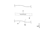
医療デバイス100は、被検者(患者)の手Hの手の甲Hbを走行する手掌動脈(深掌動脈)Bの橈骨動脈(例えば、スナッフボックス周辺の橈骨動脈やスナッフボックスよりも指先側を走行する遠位橈骨動脈等)からカテーテルやイントロデューサー等の医療用長尺体を導入するにあたり、手の甲Hbの所望の位置に穿刺部位t1を形成するために使用される。なお、穿刺部位t1を形成する位置は、手Hを走行する手掌動脈Bに医療用長尺体を挿入可能な位置であれば特に限定されず、左手、右手、手の甲側、掌側等のいずれの部位であってもよい。
本実施形態に係る医療デバイス100は、図2に示すように、第1の検出部10、第2の検出部20、第1の出力部30A、第2の出力部30B、ガイド部40、及び針組立体(「穿刺器具」に相当する)50を有する。
(第1の検出部、第2の検出部)
第1の検出部10及び第2の検出部20は、被検者の血圧を皮膚の表層側から検出する。第1の検出部10は、圧力センサ11と、支持体12と、を備える。圧力センサ11は、被検者の血圧をガイド部40の支持台41、42の幅方向Yにおいて一定の間隔で検出できるように構成している。
第1の検出部10及び第2の検出部20は、被検者の血圧を皮膚の表層側から検出する。第1の検出部10は、圧力センサ11と、支持体12と、を備える。圧力センサ11は、被検者の血圧をガイド部40の支持台41、42の幅方向Yにおいて一定の間隔で検出できるように構成している。
支持体12は、圧力センサ11に隣接して配置されるとともに圧力センサ11よりも被検者の皮膚から離間して配置している。圧力センサ11は、例えば、公知のシート型の感圧式センサにより構成することが可能である。
支持体12は、柔軟な材料で構成されることによって、被検者の装着部位に合わせて第1の検出部10を柔軟に変形可能に構成している。支持体12の材料としては、例えば、ポリウレタンやウレタン系エラストマー等を挙げることができる。
第2の検出部20は、長さ方向Xにおいて第1の検出部10と所定の距離だけ離間して配置され、第1の検出部10と異なる位置で被検者の血圧を皮膚表層側から検出する。第2の検出部20は、図2に示すように圧力センサ21及び支持体22を備える。圧力センサ21は第1の検出部10の圧力センサ11と同様であり、支持体22は第1の検出部10の支持体12と同様であるため、説明を省略する。
(出力部)
図2に示すように、支持台41には第1の出力部30Aが配置されている。第1の出力部30Aは、第1の検出部10の検出結果を出力する。
図2に示すように、支持台41には第1の出力部30Aが配置されている。第1の出力部30Aは、第1の検出部10の検出結果を出力する。
支持台42には第2の出力部30Bが配置されている。第2の出力部30Bは、第2の検出部20の検出結果を出力する。なお、第1の出力部30Aと第2の出力部30Bは実質的に同一の構成を有するため、第1の出力部30Aについて説明し、第2の出力部30Bについての説明は適宜省略する。
第1の出力部30Aは、図4に示すように、表示部31と、指示部32と、を備える。
表示部31は、支持台41において第1の検出部10の検出結果として血管走行と交差する方向の圧力分布を視覚的に表示するように構成している。表示部31は、図4に示すように第1の検出部10の圧力センサ11が検出した圧力の検出値を一例として数値のないヒストグラムにより表示する。表示部31は、ガイド部40を構成する支持台41の幅方向Yにおいて所定の間隔毎における圧力の検出結果を表示するように構成している。このように構成することによって手掌動脈Bが支持台41の幅方向Yにおけるどの位置に近接しているかを把握することができる。表示部31は、支持台41と同様に支持台42にも設けられる。なお、表示部31は、検出した圧力を数値、記号、文字、これらの組み合わせ等で表示するように構成してもよい。
指示部32は、支持台41の幅方向Yにおいて表示部31の中心位置を表示するように構成している。指示部32は、図4に示すように本実施形態において表示部31の下部において上向きの略三角形のマークにより表示される。
第2の出力部30Bは、支持台42の幅方向Yにおいて所定の間隔毎における圧力の検出結果を表示する。また、第2の出力部30Bの指示部32は、支持台41の幅方向Yにおいて表示部31の中心位置を表示する。
(ガイド部)
ガイド部40は、第1の検出部10と第2の検出部20との間(長さ方向Xにおける第1の検出部10と第2の検出部20との間の略中心位置)へ、被検者に穿刺される針組立体50の針先を誘導する。ガイド部40は、図2に示すように支持台41、42と、棒状部材43、44と、を備える。
ガイド部40は、第1の検出部10と第2の検出部20との間(長さ方向Xにおける第1の検出部10と第2の検出部20との間の略中心位置)へ、被検者に穿刺される針組立体50の針先を誘導する。ガイド部40は、図2に示すように支持台41、42と、棒状部材43、44と、を備える。
支持台41は、高さ方向Zにおいて第1の検出部10の上部に取り付けられる。支持台41は、図2に示すように針組立体50の針先を載置する凹状のガイド溝41aを備えるように構成している。第1の検出部10、第2の検出部20、第1の出力部30A、第2の出力部30Bによって被検者に対して医療デバイス100の位置合わせをした状態で、図3に示すように針組立体50の針部をガイド溝41aに載置することで、穿刺対象となる手掌動脈Bを目視した状態で穿刺できる。また、ガイド溝41aには傾斜を設けることで、針組立体50の針部をガイド溝41aに載置した状態で水平面から例えば30度傾斜した状態とし、針先を穿刺に適した角度とすることができる。また、手掌動脈Bの走行方向に沿うように、かつ、手掌動脈Bの略中央を狙って穿刺することができる。
支持台42は、第2の検出部20の上部に取り付けられる。支持台42は、支持台41から長さ方向Xに間隔を空けて配置することによって、針組立体50の針部の先端を各支持台41、42の間に誘導する。支持台41と支持台42との間の距離dは例えば、針組立体50を約30度で刺入するようにガイド溝41aが形成され、かつ、体表面から約2mmの深さで穿刺するようにする場合、5mm~10mmに設定することができる。
棒状部材43、44は、図2に示すように、長さ方向Xに間隔を空けて配置した支持台41、42を連結するように構成している。棒状部材43、44は、支持台41と支持台42の間に針組立体50の針先を誘導することが可能となるように、支持台41、42の幅方向Yに所定のスペースを空けて配置している。
(針組立体)
針組立体50は、図6に示すように、内針51と、外筒管52と、を備える。内針51及び外筒管52の先端は、図6に示すように略矩形状に形成している。これにより、穿刺した際の傷口(穿刺部位t1の平面視の形状)を図7に示すように手掌動脈Bの走行方向に沿うように延びた形状に形成することができる。血管は、一般的に伸縮性を備えるため、手掌動脈Bの走行方向に沿うように傷口を形成した場合においても、断面形状が略円形で形成された医療用長尺体を円滑に通過させることができる。また、内針51により形成された傷口は、医療用長尺体の抜去後には自然に閉じる方向に作用することが期待できる。また、上記のような穿刺部位t1の形成方法は、傷口を無理に押し広げないため、傷口を塞ぎ易くすることができる。
針組立体50は、図6に示すように、内針51と、外筒管52と、を備える。内針51及び外筒管52の先端は、図6に示すように略矩形状に形成している。これにより、穿刺した際の傷口(穿刺部位t1の平面視の形状)を図7に示すように手掌動脈Bの走行方向に沿うように延びた形状に形成することができる。血管は、一般的に伸縮性を備えるため、手掌動脈Bの走行方向に沿うように傷口を形成した場合においても、断面形状が略円形で形成された医療用長尺体を円滑に通過させることができる。また、内針51により形成された傷口は、医療用長尺体の抜去後には自然に閉じる方向に作用することが期待できる。また、上記のような穿刺部位t1の形成方法は、傷口を無理に押し広げないため、傷口を塞ぎ易くすることができる。
内針51の外側面には、図6に示すように、外筒管52に挿入された状態で外筒管52との間に血液流路を形成する凹部53a、53bが形成されている。本実施形態では、内針51の高さ方向(図6の上下方向)の異なる2箇所の位置に凹部53a、53bを設けている。内針51と外筒管52を用いて穿刺を行うと、各凹部53a、53bに手掌動脈Bからの血液が毛細管現象によって流通する。各凹部53a、53bを内針51の高さ方向の異なる位置に配置しているため、術者は、いずれの凹部53、53bを介して血液が流れているかを確認することにより、針組立体50が手掌動脈Bに対してどの程度の深さまで穿刺を行ったかが把握できる。これによって、意図せずにダブルウォールパンクチャーとなるリスクを低減し、シングルウォールパンクチャー(手掌動脈Bの体表面から手前側の血管壁のみに対する穿刺)により手掌動脈Bを捉えることができる。
なお、内針51の外表面には、内針51と皮膚との付着を防止するために、ナシジ加工やシボ加工を施してもよい。
(使用例)
次に本実施形態に係る医療デバイス100の使用例について説明する。
次に本実施形態に係る医療デバイス100の使用例について説明する。
術者は、医療デバイス100を図1に示すように手Hの手掌動脈B付近に載置し、第1の検出部10の検出結果を第1の出力部30Aに表示させ、第2の検出部20の検出結果を第2の出力部30Bに表示させる。
次に、術者は、第1の出力部30Aが示す圧力分布と第2の出力部30Bが示す圧力分布とが略同一となるように、医療デバイス100の位置を調整する。この際、術者は、第1の検出部10の検出結果が出力された第1の出力部30Aに表示された圧力分布と、第2の検出部20検出結果が出力された第2の出力部30Bに表示された圧力分布とを目視により確認し、被検者の血管走行に沿うように医療デバイス100の向き等を調整する。
術者は、上記の作業を終えた後、針組立体50を用いて穿刺を行う。この際、図3に示すように手掌動脈Bへの刺入位置と体表面への刺入位置とは、長さ方向Xに位置が変わることを考慮して穿刺を行う。また、術者は、第1の出力部30Aが示す圧力分布と第2の出力部30Bが示す圧力分布を確認しながら、長さ方向Xにおける支持台41と支持台42との間の略中心位置に穿刺位置を設定する。
穿刺の際には、図6に示す針組立体50を用いて、図7に示すように手掌動脈Bの走行方向に沿うような形状の傷口を形成する。
針組立体50が手掌動脈Bに穿刺されると、針組立体50の凹部53の中でも穿刺時に下側に位置する凹部53aから毛細管現象によって血液が流通する。そこからさらに針先を進めると、穿刺時に上側に位置する凹部53bにも逆血が見られるようになる。これにより、外筒管52の先端が手掌動脈B内を確保したことが確認できる。術者は逆血を確認した後、外筒管52を残し、内針51を引き抜く。
次に、イントロデューサーを手掌動脈Bに挿入する。血管壁には伸縮性があるため、手掌動脈Bに形成した傷口はイントロデューサーに合わせて円形に近い形になる。そのため、手掌動脈Bの壁面がさらに押し広げられることはないか、又はほとんどない状態となる。
治療等の処置が終了した後、イントロデューサーを手掌動脈Bから抜去する。穿刺部位t1は手掌動脈Bの伸縮性によって自然に閉じる方向に作用することが期待できる。また、本実施形態に係る医療デバイス100を使用すれば、傷口は無理に押し広げられないため、組織の状態は比較的きれいな状態であり、傷口が塞がり易くなる。
以上、説明したように本実施形態に係る医療デバイス100は、被検者の血圧を皮膚表層側から検出する第1の検出部10と、第1の検出部10と所定の距離だけ離間して配置され、第1の検出部10とは異なる位置で被検者の血圧を皮膚表層側から検出する第2の検出部20と、第1の検出部10の検出結果及び第2の検出部20の検出結果を出力する出力部30A、30Bと、第1の検出部10と第2の検出部20との間へ、被検者に穿刺される針組立体50の針先を誘導するガイド部40と、を有するように構成している。
医療デバイス100は、出力部30A、30Bに第1の検出部10の検出結果と第2の検出部20の検出結果を出力させることができる。そして、術者は、手掌動脈Bへの穿刺を行う際に、ガイド部40により針組立体50の針先を所望の位置へ誘導することができる。そのため、術者は、正確な位置に穿刺部位t1を形成することが可能になる。また、穿刺針は通常、穿刺部位に対して傾いた角度から穿刺を行うため、体表における穿刺位置と血管における穿刺位置は上肢等の長手方向に幾分ずれる。さらに、手掌動脈から医療用長尺体を挿入する場合、手掌動脈周辺には腱等が複雑に接近しており、穿刺部位が腱等の下方に位置した場合、体表から止血部位への圧迫が不完全になる場合がある。これに対して、本実施形態に係る医療デバイス100を使用することによって、穿刺位置を正確に検出することで止血部位への圧迫を確実に行うことができる。
また、出力部30A、30Bは、血管走行と交差する方向の圧力分布を表示する表示部31と、表示部31の中心位置を指示する指示部32と、を有するように構成している。そのため、針組立体50が血管走行に合わせて穿刺できるように医療デバイス100を被検者に対して位置合わせすることができる。
また、第1の検出部10及び第2の検出部20は、圧力センサ11、21が配置された柔軟な支持体12、22を備えるように構成している。そのため、医療デバイス100を患者の手Hの体表面に沿わせるように載置することができる。
また、医療デバイス100は、内針51と、内針51を収容する外筒管52と、を備えた針組立体50をさらに有する。内針51の針先は矩形形状を有するように構成している。このように構成することによって、針組立体50で穿刺部位t1を形成した際に傷口を無理に押し広げないようにでき、傷口を塞がり易くすることができる。
また、内針51は、外筒管52に挿入された状態で、外筒管52との間に血液流路を形成する凹部53を有するように構成している。そのため、針組立体50を穿刺した際に凹部53から毛細管現象によって血液が流通することをもって針組立体50が手掌動脈Bに対してどの程度穿刺されたのかを推測することができる。これにより、ダブルウォールパンクチャーとなるリスクを低減するとともにシングルウォールパンクチャーでも手掌動脈Bを捉えることができる。
なお、本発明は上述した実施形態にのみ限定されず、特許請求の範囲に応じて種々の変更が可能である。上記では指示部32が表示部31の中心位置を指示すると説明した。しかし、医療デバイス100を被検者の血管走行に沿うように位置合わせできれば、指示部が示す位置は表示部の中心位置でなくてもよい。
また、上記では指示部32を略三角形状のマークにて構成し、表示部31に表示された圧力分布と指示部32のマークとを合わせることで医療デバイス100の位置合わせを行うと説明した。しかし、医療デバイス100を被検者の手掌動脈Bに対して位置合わせできればこれに限定されず、上記以外にも圧力分布がガイド部40によって誘導される針先の予定穿刺位置にきたら、音等によって位置合わせされたことを使用者に通知するように構成してもよい。
本出願は、2018年3月30日に出願された日本国特許出願第2018-068192号に基づいており、その開示内容は、参照により全体として引用されている。
100 医療デバイス、
10 第1の検出部、
11、21 圧力センサ、
12、22 支持体、
20 第2の検出部、
30A 第1の出力部(出力部)、
30B 第2の出力部(出力部)、
53a、53b 凹部、
40 ガイド部、
41a ガイド溝、
50 針組立体(穿刺器具)、
51 内針、
52 外筒管、
H 手、
Hb 手の甲、
B 手掌動脈、
t1 穿刺部位。
10 第1の検出部、
11、21 圧力センサ、
12、22 支持体、
20 第2の検出部、
30A 第1の出力部(出力部)、
30B 第2の出力部(出力部)、
53a、53b 凹部、
40 ガイド部、
41a ガイド溝、
50 針組立体(穿刺器具)、
51 内針、
52 外筒管、
H 手、
Hb 手の甲、
B 手掌動脈、
t1 穿刺部位。
Claims (5)
- 被検者の血圧を皮膚表層側から検出する第1の検出部と、
前記第1の検出部と所定の距離だけ離間して配置され、前記第1の検出部とは異なる位置で前記被検者の血圧を皮膚表層側から検出する第2の検出部と、
前記第1の検出部の検出結果及び前記第2の検出部の検出結果を出力する出力部と、
前記第1の検出部と前記第2の検出部との間へ、前記被検者に穿刺される穿刺器具の針先を誘導するガイド部と、を有する医療デバイス。 - 前記出力部は、血管走行と交差する方向の圧力分布を表示する表示部と、前記表示部の中心位置を指示する指示部と、を有する請求項1に記載の医療デバイス。
- 前記第1の検出部及び前記第2の検出部は、圧力センサが配置された柔軟な支持体を有する、請求項1又は2に記載の医療デバイス。
- 内針と、前記内針を収容する外筒管と、を備えた針組立体をさらに有し、
前記内針の針先は、矩形形状を有する、請求項1~3のいずれか1項に医療デバイス。 - 前記内針は、前記外筒管に挿入された状態で、前記外筒管の内面との間に血液流路を形成する凹部を有する、請求項4に記載の医療デバイス。
Priority Applications (1)
| Application Number | Priority Date | Filing Date | Title |
|---|---|---|---|
| JP2020509238A JP7197564B2 (ja) | 2018-03-30 | 2019-03-27 | 医療デバイス |
Applications Claiming Priority (2)
| Application Number | Priority Date | Filing Date | Title |
|---|---|---|---|
| JP2018068192 | 2018-03-30 | ||
| JP2018-068192 | 2018-03-30 |
Publications (1)
| Publication Number | Publication Date |
|---|---|
| WO2019189441A1 true WO2019189441A1 (ja) | 2019-10-03 |
Family
ID=68059110
Family Applications (1)
| Application Number | Title | Priority Date | Filing Date |
|---|---|---|---|
| PCT/JP2019/013317 Ceased WO2019189441A1 (ja) | 2018-03-30 | 2019-03-27 | 医療デバイス |
Country Status (2)
| Country | Link |
|---|---|
| JP (1) | JP7197564B2 (ja) |
| WO (1) | WO2019189441A1 (ja) |
Citations (6)
| Publication number | Priority date | Publication date | Assignee | Title |
|---|---|---|---|---|
| JPH0520709U (ja) * | 1991-09-03 | 1993-03-19 | コーリン電子株式会社 | 脈波検出装置 |
| JPH067309A (ja) * | 1992-05-12 | 1994-01-18 | Nippon Colin Co Ltd | 非観血的大動脈血流測定装置とその方法 |
| JPH105199A (ja) * | 1996-06-21 | 1998-01-13 | Dainippon Printing Co Ltd | 体液分析装置 |
| US7736330B2 (en) * | 2000-08-24 | 2010-06-15 | Bardy Gust H | Subcutaneous implantation instrument with dissecting tool and method of construction |
| JP2012045156A (ja) * | 2010-08-26 | 2012-03-08 | Nihon Covidien Kk | 穿刺針及びその穿刺針を備えた穿刺針導入具 |
| JP2017006184A (ja) * | 2015-06-17 | 2017-01-12 | 株式会社日立ハイテクノロジーズ | 採血装置 |
-
2019
- 2019-03-27 WO PCT/JP2019/013317 patent/WO2019189441A1/ja not_active Ceased
- 2019-03-27 JP JP2020509238A patent/JP7197564B2/ja active Active
Patent Citations (6)
| Publication number | Priority date | Publication date | Assignee | Title |
|---|---|---|---|---|
| JPH0520709U (ja) * | 1991-09-03 | 1993-03-19 | コーリン電子株式会社 | 脈波検出装置 |
| JPH067309A (ja) * | 1992-05-12 | 1994-01-18 | Nippon Colin Co Ltd | 非観血的大動脈血流測定装置とその方法 |
| JPH105199A (ja) * | 1996-06-21 | 1998-01-13 | Dainippon Printing Co Ltd | 体液分析装置 |
| US7736330B2 (en) * | 2000-08-24 | 2010-06-15 | Bardy Gust H | Subcutaneous implantation instrument with dissecting tool and method of construction |
| JP2012045156A (ja) * | 2010-08-26 | 2012-03-08 | Nihon Covidien Kk | 穿刺針及びその穿刺針を備えた穿刺針導入具 |
| JP2017006184A (ja) * | 2015-06-17 | 2017-01-12 | 株式会社日立ハイテクノロジーズ | 採血装置 |
Also Published As
| Publication number | Publication date |
|---|---|
| JP7197564B2 (ja) | 2022-12-27 |
| JPWO2019189441A1 (ja) | 2021-04-22 |
Similar Documents
| Publication | Publication Date | Title |
|---|---|---|
| JP4790713B2 (ja) | 生体管路に術前処置を施すための装置 | |
| JP4928540B2 (ja) | 体内の生理学的な測定値を検出するための装置 | |
| JP6499961B2 (ja) | バスキュラーアクセスシステム | |
| JP6062643B2 (ja) | テーパ針を有するマイクロアクセスキット | |
| US20170281142A1 (en) | Sheath-dilator system and uses thereof | |
| JP2013176534A (ja) | 方向転換デバイス及びそれを備えた医療機器組立体 | |
| AU2016201598A1 (en) | Device for forming tracts in tissue | |
| JP2009528876A (ja) | 針誘導装置 | |
| JP2001527431A (ja) | 血管創傷閉鎖装置 | |
| DE60045163D1 (de) | Gerät zur bestimmung der tiefe eines einschnittes | |
| JP2008540017A (ja) | カニューレ挿入システム | |
| CN112638294A (zh) | 用于经皮松解程序的医疗器械 | |
| US20260000872A1 (en) | Indwelling cannula | |
| JP5274740B2 (ja) | ハンドルアセンブリ | |
| CN106852116B (zh) | 带有用于导向线的引入辅助部的气囊导管 | |
| US20150080792A1 (en) | Operating member | |
| CN103876872A (zh) | 一种更小海波管快速交换置入器 | |
| JP2015144750A (ja) | 尿道狭窄症の治療方法 | |
| US9452269B2 (en) | Method, retention device and medical treatment device for stable support of a needle to be inserted into a patient | |
| CN109661205A (zh) | 导管装置、针组件和试剂盒 | |
| JP5191823B2 (ja) | 留置針及び穿刺針 | |
| US20140187943A1 (en) | Angled needle entry | |
| KR20150101957A (ko) | 오버튜브 및 그 사용법 | |
| JP7197564B2 (ja) | 医療デバイス | |
| JP2015144752A (ja) | 尿道狭窄症の治療方法 |
Legal Events
| Date | Code | Title | Description |
|---|---|---|---|
| 121 | Ep: the epo has been informed by wipo that ep was designated in this application |
Ref document number: 19777922 Country of ref document: EP Kind code of ref document: A1 |
|
| ENP | Entry into the national phase |
Ref document number: 2020509238 Country of ref document: JP Kind code of ref document: A |
|
| 122 | Ep: pct application non-entry in european phase |
Ref document number: 19777922 Country of ref document: EP Kind code of ref document: A1 |