WO2019188656A1 - 医療デバイスの制御装置及び流体の流量を制御する方法 - Google Patents
医療デバイスの制御装置及び流体の流量を制御する方法 Download PDFInfo
- Publication number
- WO2019188656A1 WO2019188656A1 PCT/JP2019/011689 JP2019011689W WO2019188656A1 WO 2019188656 A1 WO2019188656 A1 WO 2019188656A1 JP 2019011689 W JP2019011689 W JP 2019011689W WO 2019188656 A1 WO2019188656 A1 WO 2019188656A1
- Authority
- WO
- WIPO (PCT)
- Prior art keywords
- medical device
- flow rate
- fluid
- treatment
- suction
- Prior art date
- Legal status (The legal status is an assumption and is not a legal conclusion. Google has not performed a legal analysis and makes no representation as to the accuracy of the status listed.)
- Ceased
Links
Images





Classifications
-
- A—HUMAN NECESSITIES
- A61—MEDICAL OR VETERINARY SCIENCE; HYGIENE
- A61B—DIAGNOSIS; SURGERY; IDENTIFICATION
- A61B17/00—Surgical instruments, devices or methods
- A61B17/32—Surgical cutting instruments
- A61B17/3205—Excision instruments
- A61B17/3207—Atherectomy devices working by cutting or abrading; Similar devices specially adapted for non-vascular obstructions
- A61B17/320758—Atherectomy devices working by cutting or abrading; Similar devices specially adapted for non-vascular obstructions with a rotating cutting instrument, e.g. motor driven
-
- A—HUMAN NECESSITIES
- A61—MEDICAL OR VETERINARY SCIENCE; HYGIENE
- A61B—DIAGNOSIS; SURGERY; IDENTIFICATION
- A61B90/00—Instruments, implements or accessories specially adapted for surgery or diagnosis and not covered by any of the groups A61B1/00 - A61B50/00, e.g. for luxation treatment or for protecting wound edges
- A61B90/03—Automatic limiting or abutting means, e.g. for safety
-
- A—HUMAN NECESSITIES
- A61—MEDICAL OR VETERINARY SCIENCE; HYGIENE
- A61M—DEVICES FOR INTRODUCING MEDIA INTO, OR ONTO, THE BODY; DEVICES FOR TRANSDUCING BODY MEDIA OR FOR TAKING MEDIA FROM THE BODY; DEVICES FOR PRODUCING OR ENDING SLEEP OR STUPOR
- A61M1/00—Suction or pumping devices for medical purposes; Devices for carrying-off, for treatment of, or for carrying-over, body-liquids; Drainage systems
- A61M1/71—Suction drainage systems
- A61M1/74—Suction control
-
- A—HUMAN NECESSITIES
- A61—MEDICAL OR VETERINARY SCIENCE; HYGIENE
- A61M—DEVICES FOR INTRODUCING MEDIA INTO, OR ONTO, THE BODY; DEVICES FOR TRANSDUCING BODY MEDIA OR FOR TAKING MEDIA FROM THE BODY; DEVICES FOR PRODUCING OR ENDING SLEEP OR STUPOR
- A61M1/00—Suction or pumping devices for medical purposes; Devices for carrying-off, for treatment of, or for carrying-over, body-liquids; Drainage systems
- A61M1/71—Suction drainage systems
- A61M1/77—Suction-irrigation systems
-
- A—HUMAN NECESSITIES
- A61—MEDICAL OR VETERINARY SCIENCE; HYGIENE
- A61B—DIAGNOSIS; SURGERY; IDENTIFICATION
- A61B90/00—Instruments, implements or accessories specially adapted for surgery or diagnosis and not covered by any of the groups A61B1/00 - A61B50/00, e.g. for luxation treatment or for protecting wound edges
- A61B90/03—Automatic limiting or abutting means, e.g. for safety
- A61B2090/033—Abutting means, stops, e.g. abutting on tissue or skin
-
- A—HUMAN NECESSITIES
- A61—MEDICAL OR VETERINARY SCIENCE; HYGIENE
- A61B—DIAGNOSIS; SURGERY; IDENTIFICATION
- A61B2217/00—General characteristics of surgical instruments
- A61B2217/002—Auxiliary appliance
- A61B2217/005—Auxiliary appliance with suction drainage system
-
- A—HUMAN NECESSITIES
- A61—MEDICAL OR VETERINARY SCIENCE; HYGIENE
- A61B—DIAGNOSIS; SURGERY; IDENTIFICATION
- A61B2217/00—General characteristics of surgical instruments
- A61B2217/002—Auxiliary appliance
- A61B2217/007—Auxiliary appliance with irrigation system
-
- A—HUMAN NECESSITIES
- A61—MEDICAL OR VETERINARY SCIENCE; HYGIENE
- A61B—DIAGNOSIS; SURGERY; IDENTIFICATION
- A61B2562/00—Details of sensors; Constructional details of sensor housings or probes; Accessories for sensors
- A61B2562/02—Details of sensors specially adapted for in-vivo measurements
- A61B2562/0247—Pressure sensors
-
- A—HUMAN NECESSITIES
- A61—MEDICAL OR VETERINARY SCIENCE; HYGIENE
- A61M—DEVICES FOR INTRODUCING MEDIA INTO, OR ONTO, THE BODY; DEVICES FOR TRANSDUCING BODY MEDIA OR FOR TAKING MEDIA FROM THE BODY; DEVICES FOR PRODUCING OR ENDING SLEEP OR STUPOR
- A61M2205/00—General characteristics of the apparatus
- A61M2205/13—General characteristics of the apparatus with means for the detection of operative contact with patient, e.g. lip sensor
-
- A—HUMAN NECESSITIES
- A61—MEDICAL OR VETERINARY SCIENCE; HYGIENE
- A61M—DEVICES FOR INTRODUCING MEDIA INTO, OR ONTO, THE BODY; DEVICES FOR TRANSDUCING BODY MEDIA OR FOR TAKING MEDIA FROM THE BODY; DEVICES FOR PRODUCING OR ENDING SLEEP OR STUPOR
- A61M2205/00—General characteristics of the apparatus
- A61M2205/18—General characteristics of the apparatus with alarm
-
- A—HUMAN NECESSITIES
- A61—MEDICAL OR VETERINARY SCIENCE; HYGIENE
- A61M—DEVICES FOR INTRODUCING MEDIA INTO, OR ONTO, THE BODY; DEVICES FOR TRANSDUCING BODY MEDIA OR FOR TAKING MEDIA FROM THE BODY; DEVICES FOR PRODUCING OR ENDING SLEEP OR STUPOR
- A61M2205/00—General characteristics of the apparatus
- A61M2205/33—Controlling, regulating or measuring
- A61M2205/3331—Pressure; Flow
- A61M2205/3344—Measuring or controlling pressure at the body treatment site
-
- A—HUMAN NECESSITIES
- A61—MEDICAL OR VETERINARY SCIENCE; HYGIENE
- A61M—DEVICES FOR INTRODUCING MEDIA INTO, OR ONTO, THE BODY; DEVICES FOR TRANSDUCING BODY MEDIA OR FOR TAKING MEDIA FROM THE BODY; DEVICES FOR PRODUCING OR ENDING SLEEP OR STUPOR
- A61M2205/00—General characteristics of the apparatus
- A61M2205/50—General characteristics of the apparatus with microprocessors or computers
Definitions
- the present invention relates to a medical device control apparatus for causing a fluid to flow through a long tubular medical device inserted into a living body and a method for controlling the flow rate of the fluid.
- a medical device having a long tubular shaft portion to be inserted into a living body and a treatment portion provided at a tip portion of the shaft portion is known.
- a medical device for example, an atherectomy that cuts a stenosis such as a thrombus by using a rotating body that is rotated by a drive shaft provided in a shaft portion as a treatment portion and rotating the rotating body in a living body lumen.
- a suction source such as a pump or a syringe for sucking an internal fluid is connected to the shaft portion in order to remove the cut constriction.
- a liquid supply source such as a pump or a syringe for supplying fluid to the inside is connected to the shaft portion.
- the medical device When the medical device is inserted into the living body, blood is present inside the medical device. While the treatment portion is not performing treatment, such as while the treatment portion is being delivered to the target site, blood stays inside the medical device. This can cause a thrombus within the medical device. When a thrombus is generated inside the medical device, the suction force by the suction source is reduced, and there is a risk that the generated thrombus may cause peripheral embolism and a risk that the rotation of the drive shaft is hindered to reduce the treatment effect. In addition, a decrease in suction force in the medical device reduces the efficiency of excluding the living tissue piece generated as a result of the treatment by the treatment unit, and increases the risk of peripheral embolization by the living tissue piece.
- the present invention has been made to solve the above-described problems, and provides a control device for a medical device and a method for controlling the flow rate of a fluid capable of suppressing the occurrence of a thrombus inside the medical device during a time other than during treatment.
- the purpose is to do.
- a medical device control device that achieves the above object is a control device for a long tubular medical device that is inserted into a living body and is provided with a treatment section for treating an object of a living body lumen at a distal end portion.
- a suction source or a liquid supply source connected to the medical device, and a control unit that controls a flow rate of a fluid flowing through the medical device, wherein the control unit is (1) the medical device. If the suction source is connected to the device, the suction source is controlled, and during the treatment by the treatment section, the fluid inside the medical device is sucked at the first flow rate, and the medical device is inserted into the living body.
- the fluid inside the medical device is sucked at a second flow rate that is smaller than the first flow rate during the period other than during the treatment, or (2) the liquid supply source is in the medical device If connected
- the liquid supply source is controlled, and at the time of treatment by the treatment section, a fluid is fed into the medical device at a third flow rate, and the medical device is inserted into the living body and at the time of the treatment.
- the fluid is fed into the medical device at a fourth flow rate smaller than the third flow rate.
- the medical device control apparatus that achieves the above object is a long tubular medical device control apparatus that is inserted into a living body and is provided with a treatment section that treats a body lumen object at a distal end portion.
- a suction source connected to the medical device, a liquid supply source connected to the medical device, and a control unit for controlling a flow rate of a fluid flowing inside the medical device,
- the control unit controls (1) the suction source, and during the treatment by the treatment unit, the fluid inside the medical device is sucked at the first flow rate, and the medical device is inserted into the living body.
- the fluid inside the medical device is aspirated at a second flow rate smaller than the first flow rate except during the treatment, and (2) the liquid supply source is controlled and treatment by the treatment unit Sometimes within the medical device
- the fluid is fed at a third flow rate, and the fluid is smaller than the third flow rate inside the medical device while the medical device is inserted into the living body and not during the treatment.
- the liquid is fed at a flow rate of 4.
- a method for controlling the flow rate of a fluid according to the present invention that achieves the above object is to suck a liquid supply source or a fluid for feeding a fluid to the inside of the medical device to a medical device provided with a treatment portion at a distal end portion.
- a fluid source is connected to the liquid supply source or the suction source at a constant flow rate while the medical device is stopped by connecting a suction source to be operated and operating a control unit that controls the flow rate of the fluid.
- fluid is caused to flow to the liquid supply source or suction source at a flow rate greater than the constant flow rate.
- the control device for a medical device configured as described above allows fluid to flow inside the medical device while the medical device is inserted into the living body and not during treatment. Can prevent thrombus formation.
- the fluid flows to the liquid supply source or the suction source at a constant flow rate even while the medical device is stopped. Generation can be suppressed.
- the side of the medical device 10 that is inserted into the living body lumen is referred to as “tip” or “tip side”
- the proximal side for operation is referred to as “base end” or “base end side”.
- the medical device system according to the embodiment of the present invention is used for a procedure of cutting a stenosis or occlusion due to plaque or thrombus in a blood vessel.
- the medical device system includes a medical device 10 that is inserted into a living body and a control device 11 that causes fluid to flow inside the medical device 10.
- the medical device 10 is an atherectomy device that cuts a stenosis or occlusion in a blood vessel by a rotating operation.
- the medical device 10 includes a long shaft portion 20, a rotatable treatment portion 21 provided at a distal end portion of the shaft portion 20, and an operation portion 22 provided at a proximal end portion of the shaft portion 20. And have.
- the operation unit 22 includes a housing 40 that is operated by a surgeon with a hand, and the housing 40 is provided with a rotation switch 41 that performs operations to start and stop the rotation of the treatment unit 21.
- the control device 11 has a suction pump 53 that is a suction source that sucks fluid from the medical device 10 and a liquid feed pump 54 that is a liquid feed source that sends fluid to the medical device 10.
- the suction pump 53 is connected to the medical device 10 by a suction tube 45 so that fluid can flow therethrough.
- the liquid feed pump 54 is connected to the medical device 10 by a liquid feed tube 47 so that fluid can flow.
- the suction pump 53 discharges the fluid sucked from the medical device 10 to a discharge unit (not shown).
- the liquid feeding pump 54 receives a supply of fluid from the fluid source 60 and sends the liquid to the medical device 10.
- the fluid source 60 stores physiological saline as a fluid.
- the control device 11 further includes a priming switch 56 for performing a priming start operation, and a display unit 57 for displaying the state of suction or liquid feeding.
- the display unit 57 can display the state of suction or liquid feeding with light using an LED.
- the control device 11 includes a fluid control unit 50 and a drive control unit 52.
- the fluid control unit 50 and the drive control unit 52 are combined to be a control unit.
- the drive control unit 52 is connected to each of the suction pump 53 and the liquid feeding pump 54 of the control device 11 and a rotation motor 49 provided in the operation unit 22 of the medical device 10, and can perform rotation control thereof.
- the fluid control unit 50 can control the drive control unit 52.
- the fluid control unit 50 controls the start and stop of rotation of the treatment unit 21 in the medical device 10 and controls the flow rate of suction by the suction pump 53 and the flow rate of liquid feed by the liquid feed pump 54 in the control device 11. it can.
- the control device 11 includes a power supply unit 55 that supplies power to the fluid control unit 50 and the drive control unit 52, and an input / output unit 51 that inputs and outputs signals to and from the fluid control unit 50.
- the input / output unit 51 is connected to the priming switch 56 and the display unit 57 described above and a bubble detector 58 that detects bubbles in the fluid from the fluid source 60.
- the bubble detector 58 detects the bubbles mixed in the liquid from the fluid source 60 and the state in which the liquid stored in the fluid source 60 is exhausted, and stops fluid control so that air is mixed into the blood vessel. To prevent.
- the fluid control unit 50 is connected to a rotation switch 41 provided in the operation unit 22 of the medical device 10.
- the shaft portion 20 of the medical device 10 includes a rotatable drive shaft 30 having a treatment portion 21 at a distal end portion, an outer sheath 31 that covers the outer side of the drive shaft 30, and an outer side of the drive shaft 30. And an inner sheath 32 provided inside the outer sheath 31.
- the drive shaft 30, the inner sheath 32, and the outer sheath 31 are disposed concentrically.
- Inside the drive shaft 30 is a guide wire lumen 33 through which a guide wire (not shown) is inserted.
- a liquid feeding lumen 34 through which fluid fed from the liquid feeding pump 54 circulates.
- Outside the inner sheath 32 and inside the outer sheath 31 is a suction lumen 35 through which the fluid sucked by the suction pump 53 flows.
- the distal end portion of the treatment portion 21 has a cutting portion 21a for cutting the narrowed portion or the closed portion.
- the proximal end portion of the treatment portion 21 extends to the inside of the outer sheath 31, is fixed to the drive shaft 30, and a bearing portion 21b is provided between the outer sheath 31 and the outer peripheral side.
- the drive shaft 30 has a proximal end extending to the inside of the housing 40 and is fixed to a rotary motor 49 provided in the housing 40.
- a drive shaft holding portion 48 is provided inside the housing 40 on the tip side of the rotary motor 49, and the housing 40 rotatably holds the drive shaft 30 via a seal portion 48a.
- the proximal end portion of the outer sheath 31 extends into the housing 40.
- the housing 40 has an outer sheath holding portion 42 that holds the outer sheath 31, and the housing 40 holds the outer sheath 31 or makes the lumen liquid-tight through a seal portion 42a.
- the tip of the inner sheath 32 is located in the middle of the outer sheath 31. For this reason, the tip of the liquid feeding lumen 34 is located in the middle part of the outer sheath 31.
- the fluid fed to the liquid feeding lumen 34 is turned back at the tip of the inner sheath 32 and flows toward the suction lumen 35.
- a proximal end portion of the inner sheath 32 extends into the housing 40.
- the housing 40 includes an inner sheath holding portion 43 that holds the inner sheath 32, and a proximal end portion of the inner sheath 32 is fixed to the inner sheath holding portion 43.
- the housing 40 has a suction port 44 to which a suction tube 45 is connected and a liquid feeding port 46 to which a liquid feeding tube 47 is connected.
- the suction port 44 communicates with the suction lumen 35 of the shaft portion 20.
- the liquid supply port 46 communicates with the liquid supply lumen 34 of the shaft portion 20.
- the narrowed portion in the blood vessel is cut by the medical device 10.
- an introducer sheath (not shown) is inserted percutaneously into the blood vessel upstream of the stenosis of the blood vessel, and a guide wire (not shown) is inserted through the introducer sheath. Is inserted into the blood vessel.
- priming is first performed on the medical device 10 (S1).
- the priming is started by operating the priming switch 56 of the control device 11.
- Priming is performed by suction and liquid feeding from the control device 11 to the medical device 10, and the shaft portion 20 is filled with fluid. Even when the priming is completed, the suction and liquid feeding to the shaft portion 20 are continued in a low flow rate state (S2).
- the medical device 10 is inserted into the blood vessel while the suction and liquid feeding to the shaft portion 20 are maintained, and the treatment portion 21 is delivered to the target site while being guided by the guide wire.
- the surgeon When the treatment unit 21 is delivered to the target site, the surgeon operates the rotary switch 41 of the operation unit 22 to rotate the drive shaft 30 (S4). Simultaneously with the start of rotation of the drive shaft 30, the flow rate of suction and liquid delivery to the medical device 10 is increased. The treatment portion 21 is rotated by the drive shaft 30 to cut the narrowed portion. The cut plaque or thrombus is drawn into the outer sheath 31 in which the inside is sucked, and is discharged from the suction port 44 through the suction lumen 35. It should be noted that the start of rotation of the drive shaft 30 and the timing of suction and liquid feeding with respect to the medical device 10 do not have to be the same, and either one may precede for a certain time.
- the operator After completing the cutting of the constricted portion, the operator operates the rotary switch 41 of the operation portion 22 to stop the drive shaft 30 (S6).
- the drive shaft 30 When the drive shaft 30 is stopped, the flow rate of suction and liquid feeding to the shaft portion 20 is reduced to a low flow rate state (S7).
- the time from the stop of the drive shaft 30 to the reduction of the flow rate of suction and liquid feeding to the shaft portion 20 may be the same, or by shifting for a certain time, the shaved lesion portion is discharged out of the body without being lost. You may do it. For example, when another stenosis part is treated, the treatment part 21 is moved within the blood vessel, and the steps from S4 are repeated.
- the medical device 10 When the treatment is completed (S8), the medical device 10 is removed from the blood vessel (S9). Also at this time, suction and liquid feeding to the shaft portion 20 are continued at a low flow rate. When the medical device 10 is removed from the living body, suction and liquid feeding to the shaft portion 20 are stopped (S10).
- the control of the suction pump 53 and the liquid feed pump 54 by the fluid control unit 50 in such treatment will be described.
- the priming switch 56 of the control device 11 is operated at time T 1.
- the fluid control unit 50 activates the suction pump 53 is rotated at a rotational speed R 1.
- the fluid control unit 50 starts the liquid feed pump 54 with a slight delay from the suction pump 53 and rotates it at the rotation speed R 4 .
- physiological saline is injected into the medical device 10 from the liquid supply port 46, flows through the shaft portion 20 at a constant flow rate, and is discharged from the suction port 44.
- the priming automatically ends after a predetermined time has elapsed since the priming switch 56 was operated.
- the fluid control unit 50 reduces the rotational speed of the suction pump 53 from R 1 to R 2 at time T 2 . Further, the fluid control unit 50 reduces the rotational speed of the liquid feed pump 54 from R 4 to R 5 at time T 3 . Thereby, although the flow volume of the fluid which flows through the inside of the shaft part 20 falls from the time of priming, the flow at a low flow volume is continued. In this state, the medical device 10 is inserted in S3 described above. Even while the treatment portion 21 is being delivered to the target site, it is possible to prevent blood from staying inside the shaft portion 20 and causing thrombus to occur due to the fluid flowing inside the shaft portion 20.
- Rotational speed R 2 of the suction pump 53 at the time of a low flow rate is larger than the rotation speed R 5 of the liquid supply pump 54. For this reason, the amount of suction by the suction pump 53 becomes larger than the amount of liquid fed from the liquid feed pump 54, and blood in the blood vessel is sucked. Since blood pressure is present in the blood vessel, the fluid in the shaft portion 20 can be caused to flow while suppressing the pressure applied to the seal portion 48a and securing the sealing performance by giving priority to suction over the liquid feeding. Moreover, by giving priority to suction over liquid feeding, the thrombus in the shaft portion 20 can be pushed into the blood vessel, and the risk of peripheral embolization can be reduced.
- the liquid conveyance amount per rotation of the suction pump 53 and the liquid feed pump 54 is equal.
- the magnitude of the suction amount / liquid feeding amount here corresponds to the flow direction of the liquid in the shaft portion 20. If the suction amount is larger than the liquid feeding amount, the liquid flows in the proximal direction near the tip of the shaft portion 20, and conversely, if the liquid feeding amount is larger than the suction amount, it is near the tip of the shaft portion 20 in the distal direction. It means that the liquid flows.
- Treatment portion 21 is delivered to the target site, the operator operates the rotary switch 41 of the operation section 22 at time T 4, as described above, the drive shaft 30 and the treatment portion 21 is rotated by the rotary motor 49.
- the fluid control unit 50 increases the rotational speed of the suction pump 53 from R 2 to R 3 .
- the fluid control unit 50 increases the rotation speed of the liquid feed pump 54 from R 5 to R 6 .
- Treatment portion 21 cutting is completed by, operator by operating the rotary switch 41 of the operation section 22 at time T 5, the rotation motor 49 is stopped, the drive shaft 30 and the treatment portion 21 is also stopped.
- the fluid control unit 50 reduces the rotation speed of the suction pump 53 from R 3 to R 2 .
- the fluid control unit 50 reduces the rotational speed of the liquid feed pump 54 from R 6 to R 5 .
- the medical device 10 is removed in S9 described above, or the treatment portion 21 is rearranged in the blood vessel. Even after the treatment by the treatment portion 21, until the medical device 10 is removed from the blood vessel, the fluid is flowing inside the shaft portion 20, so that blood stays inside the shaft portion 20 and a thrombus is generated. Can be suppressed.
- the stop of the liquid flow at time T 8 it is detected that the medical device 10 is removed from the vessel by a sensor or the like, may be performed automatically by the fluid control part 50, located in a control device 11
- the switch or the like may be manually performed by an operator or a user inputting and operating the switch.
- Figure 4 at time T 8, but shows a flow of actions when stopping the liquid flow, without stopping the fluid flow after device removal (S9), it may be continued.
- the fluid control unit 50 sucks at a large flow rate (first flow rate) and sends a liquid at a large flow rate (third flow rate). While 21 is not performing treatment, suction is performed at a second flow rate smaller than the first flow rate, and liquid is fed at a fourth flow rate smaller than the third flow rate.
- the second flow rate and the fourth flow rate are minimum flow rates in the suction pump 53 and the liquid feed pump 54, respectively.
- the thrombus generation in the shaft portion 20 can be suppressed by setting the flow rate of the fluid in the suction lumen 35 to 5 ml / min.
- the flow rate is not limited to this, and can be 1 to 50 ml / min, preferably 1 to 10 ml / min when an atherectomy procedure time is assumed.
- insertion into the blood vessel is started in a state where suction and liquid feeding are performed at a low flow rate with respect to the shaft portion 20, but after the insertion into the blood vessel is started, the shaft portion 20 is started.
- Suction and liquid feeding at a low flow rate may be started. Specifically, it may be automatically started by detecting the insertion state of the shaft portion 20 into the blood vessel with a sensor or the like, or automatically after the first treatment operation is completed (S8). May be. The configuration for detecting the insertion state into the blood vessel with a sensor will be described later.
- an operation unit such as a switch may be provided in either or both of the control device 11 and the housing 40 and may be manually started by an operation by an operator or a user.
- suction and liquid feeding at a low flow rate to the shaft portion 20 are stopped, but before the removal of the medical device 10 from the blood vessel is completed, the shaft portion 20 is removed. Suction and liquid feeding at a low flow rate may be stopped.
- the suction and liquid feeding before and after the medical device 10 is removed from the blood vessel may be automatically stopped by detecting the state of insertion into the blood vessel with a sensor or the like, as in the above-described insertion.
- 11 or the housing 40 may be provided with an operation unit such as a switch and manually stopped by an operation by an operator or a user.
- suction and liquid feeding at a low flow rate with respect to the shaft portion 20 may be continued without stopping.
- priming may be performed, and the medical device 10 may be inserted into the blood vessel again.
- the fluid is allowed to flow at a low flow rate so that the inside of the shaft unit 20 Therefore, it is possible to prevent blood from staying and causing thrombus.
- you may perform priming in the state in which the medical device 10 exists in a body.
- both the suction pump 53 and the liquid feeding pump 54 are operated at a constant rotational speed. Yes.
- the suction pump 53 may be operated intermittently at the rotational speed R 2 ′ while the liquid feed pump 54 is operated at a constant rotational speed.
- the suction pump 53 is set to R 7 smaller than R 2
- the rotation speed of the liquid feeding pump 54 is set to R 8 larger than R 5.
- the rotation speed may be greater than 53.
- the amount of liquid fed by the liquid feed pump 54 is larger than the amount of suction by the suction pump 53, and physiological saline is injected into the blood vessel. For this reason, the amount of blood sucked can be reduced, and the blood loss in the treatment can be suppressed.
- liquid feeding is prioritized over suction, the physiological saline concentration in the shaft portion 20 can be increased and the blood concentration can be decreased, so that thrombus generation in the shaft portion 20 can be further suppressed.
- the suction pump 53 is operated at a constant rotational speed, while the liquid feeding pump 54 is intermittent at a rotational speed R 8 ′. You may make it drive
- the suction pump 53 performs intermittent operation of the rotational speed R 9, it may be also liquid supply pump 54 performs an intermittent operation of the rotational speed R 10.
- the suction pump 53 and the liquid feed pump 54 operate alternately, but may be synchronized or may be operated at a certain interval. Thereby, the quantity of the physiological saline which flows into a patient's body can be reduced, suppressing a patient's blood loss amount.
- the control device 11 may have a notification unit and an operation unit for that purpose.
- a notification unit that measures the time after the medical device 10 is inserted into the living body and the treatment time, and notifies the operator by voice or light when a certain time has elapsed.
- a notifying unit that measures the blood loss after the medical device 10 is inserted into the living body at or near the suction pump 53 and notifies by voice or light when the blood loss exceeds a certain value. it can.
- the control device 11 or the housing 40 may emit sound (such as a beep at a constant interval) or light (such as blinking light) during suction and liquid feeding at a low flow rate with respect to the shaft portion 20. .
- sound such as a beep at a constant interval
- light such as blinking light
- a pause operation unit that temporarily stops the suction by the suction pump 53 may be provided in the control device 11 or the housing 40.
- the operator or the user can easily and immediately cope with the operation of the pause operation unit.
- the sound or light may be notified, or the suction or liquid feeding may be forcibly restarted.
- a sensor unit 70 composed of a pressure sensor can be provided in the housing 40 of the unit 22.
- the sensor unit 70 is provided at a position communicating with the suction lumen 35.
- the fluid control unit 50 starts suction and liquid feeding at a low flow rate with respect to the shaft unit 20 as described above. Further, when the sensor unit 70 detects a pressure drop corresponding to the blood pressure, the fluid control unit 50 stops suction and liquid feeding at a low flow rate with respect to the shaft unit 20 assuming that the shaft unit 20 is removed from the blood vessel.
- the arrangement position of the sensor unit 70 which is a pressure sensor, is not limited to the example in FIG. 9, and may be a position where blood pressure due to reverse blood can be detected.
- the blood pressure from the blood vessel is detected by the sensor unit 70 via the suction lumen 35, but a pressure detection lumen is separately provided on the shaft unit 20 or another shaft member, and the lumen is passed through this lumen.
- the sensor unit 70 may detect the pressure.
- the sensor unit 71 may be formed of a push button switch exposed to the outside of the operation unit 22.
- the sensor unit 71 can detect whether or not the operation unit 22 is placed on a table or a holder.
- the fluid control unit 50 performs suction and liquid feeding on the shaft unit 20 on the assumption that the medical device is not inserted into the blood vessel. Absent.
- the sensor unit 71 detects that the operation unit 22 has moved away from the table or the like, it is assumed that the medical device has been inserted into the blood vessel, and the fluid control unit 50 starts suction and liquid feeding to the shaft unit 20.
- the medical device control apparatus is a control apparatus for the long tubular medical device 10 that is inserted into a living body and is provided with a treatment unit that treats a body lumen object at the distal end. 11, a suction source 53 or a liquid supply source 54 connected to the medical device 10, and a control unit 50 that controls the flow rate of the fluid that flows inside the medical device 10.
- the suction source 53 is connected to the medical device 10
- the suction source 53 is controlled, and during the treatment by the treatment unit 21, the fluid inside the medical device 10 is sucked at the first flow rate so that the medical device 10 is in vivo.
- the fluid inside the medical device 10 is aspirated at a second flow rate that is smaller than the first flow rate, or the liquid supply source 54 is connected to the medical device 10.
- the liquid supply source 54 is controlled, and at the time of the treatment by the treatment unit 21, the fluid is fed into the medical device 10 at the third flow rate, and the treatment is performed while the medical device 10 is inserted into the living body.
- the fluid is supplied into the medical device 10 at a fourth flow rate smaller than the third flow rate.
- control device 11 of the medical device 10 is inserted into the living body, and the control device of the long tubular medical device 10 provided with the treatment portion 21 that treats the object of the living body lumen at the distal end portion. 11, a suction source 53 connected to the medical device 10, a liquid supply source 54 connected to the medical device 10, and a control unit 50 that controls the flow rate of the fluid flowing inside the medical device 10.
- the control unit 50 controls the suction source 53 when the medical device 10 is connected to the medical device 10, and sucks the fluid inside the medical device 10 at the first flow rate during the treatment by the treatment unit 21.
- the fluid inside the medical device 10 is aspirated at a second flow rate smaller than the first flow rate, and the medical device 10 Sent to
- the liquid supply source 54 is controlled, and at the time of the treatment by the treatment unit 21, the fluid is fed into the medical device 10 at the third flow rate, and the medical device 10 is inserted into the living body.
- the fluid is fed into the medical device 10 at a fourth flow rate smaller than the third flow rate during the period other than the treatment.
- control unit 50 can control the suction source 53 and the liquid supply source 54 so that the second flow rate is larger than the fourth flow rate.
- suction is prioritized over liquid feeding, and the fluid in the medical device 10 can be flowed while ensuring the sealing performance with respect to the drive shaft 30.
- the thrombus in the medical device 10 can be prevented from being pushed out into the blood vessel.
- control unit 50 can control the suction source 53 and the liquid supply source 54 so that the fourth flow rate is larger than the second flow rate.
- the control unit 50 can cause the suction source 53 to suck at a flow rate larger than the second flow rate when the medical device 10 is primed. Thereby, while shortening the priming time of the medical device 10, the fluid can flow through the inside of the medical device 10 at a low flow rate except during treatment.
- the control unit 50 can cause the liquid supply source 54 to supply liquid at the fourth flow rate when the medical device 10 is primed. Thereby, while shortening the priming time of the medical device 10, the fluid can flow through the inside of the medical device 10 at a low flow rate except during treatment.
- control unit 51 can rotate the medical device 10 at a lower speed than during the treatment while the medical device 10 is being inserted into the living body and other than during the treatment.
- the fluid inside the medical device 10 can be made to flow by the low-speed rotation of the medical device 10, and the flow of the fluid inside the medical device 10 during the time other than during the treatment can be promoted, and thrombus formation can be suppressed.
- the control unit 50 uses the sensor unit 70 to generate the medical device 10. If the fluid inside the shaft portion 20 is allowed to flow at the second flow rate during detection of the state of being inserted into the body and other than during treatment, the medical device 10 becomes in vivo. The fluid can be automatically flowed at the second flow rate while being inserted into the.
- the control unit 50 uses the sensor unit 70 to connect the medical device 10. If the fluid inside the medical device 10 is allowed to flow at the fourth flow rate while it is being detected that it is inserted into the living body and not during the treatment, the medical device 10 will be live. While inserted into the body, the fluid can automatically flow at the fourth flow rate.
- the control unit 50 temporarily stops the suction when the fluid inside the medical device 10 is sucked at the second flow rate. If the operation unit is further provided, the operator or the user can easily and immediately cope with the operation of the pause operation unit when it is desired to reduce the blood loss during the treatment.
- control unit 50 temporarily stops the liquid supply when the fluid is supplied into the medical device 10 at the fourth flow rate. If a temporary stop operation unit is further provided, an operator or user can easily and immediately cope with the operation of the temporary stop operation unit when it is desired to reduce the blood loss during the treatment.
- control unit 50 When the suction source 53 is connected to the medical device 10, the control unit 50 is sucking the fluid inside the medical device 10 at the second flow rate, or the liquid supply source 54 is connected to the medical device 10. If connected, the control unit 50 may further include a notifying unit for notifying by voice or light that the fluid is being fed into the medical device 10 at the fourth flow rate. An informing part can be used for the control.
- the medical device system control method includes a medical device 10 having a long tubular shaft portion 20 that can be inserted into a living body, a treatment portion 21 provided at a distal end portion of the shaft portion 20, and a shaft. And a fluid control unit 50 that controls the flow rate of the fluid flowing inside the unit 20.
- the fluid control unit 50 inserts the shaft unit 20 into a living body and inserts the treatment unit 21 into the living body.
- the fluid is flowed at a constant flow rate in the shaft unit 20 until the treatment by the fluid control unit 50 is started, and the fluid control unit 50 starts the treatment by the treatment unit 21 and ends the treatment.
- the fluid is flowed at a flow rate greater than a certain flow rate, and the fluid control unit 50 performs the shaft portion until the treatment by the treatment portion 21 is completed and the shaft portion 20 is removed from the living body.
- the fluid control unit 50 performs the shaft portion until the treatment by the treatment portion 21 is completed and the shaft portion 20 is removed from the living body.
- Inside of 0 flowing the fluid at a constant flow rate.
- Fluid flow during times other than during treatment may be realized by automatic control by software, or may be realized by detecting a state in which the medical device 10 is in the body using a sensor, or the control device 11 or a housing.
- An operation unit may be provided in either or both of the 40, and the operation may be realized by an operation by an operator or a user.
- the method for controlling the flow rate of the fluid in the present embodiment is a method of sucking the fluid supply source 54 or the fluid for feeding the fluid to the inside of the medical device 10 to the medical device 10 in which the treatment portion 21 is provided at the distal end portion.
- the medical device 10 is stopped by connecting the suction source 53 to be operated and operating the control unit 50 that controls the flow rate of the fluid, the fluid is caused to flow to the liquid supply source 54 or the suction source 53 at a constant flow rate.
- the device 10 is operating, the fluid is flowed to the liquid supply source 54 or the suction source 53 at a flow rate larger than a constant flow rate.
- the fluid is caused to flow to the liquid supply source 54 or the suction source 53 at a constant flow rate, so that thrombus generation can be suppressed inside the medical device 10.
- suction is performed by the suction pump 53 and liquid feeding is performed by the liquid feeding pump 54.
- suction or liquid feeding may be performed by other means.
- suction or liquid feeding may be performed using a syringe.
- blood may be discharged to the outside through the shaft portion 20 by the blood pressure in the blood vessel.
- the fluid control unit 50 controls the number of rotations of the suction pump 53 and the liquid feeding pump 54, so that the suction amount and the liquid feeding amount while the treatment by the treatment unit 21 is not performed are set.
- the difference between the suction amount and the liquid feeding amount may be controlled by other means.
- the number of rotations of the suction pump 53 and the liquid feeding pump 54 are the same, and the amount of suction and the amount of feeding during the time when the treatment by the treatment unit 21 is not performed due to the difference in inner diameter between the suction tube 45 and the liquid feeding tube 47.
- the difference from the liquid volume may be controlled.
- the difference between the suction amount and the liquid feed amount may be controlled by the suction pump 53 and the liquid feed pump 54 having different fluid discharge amounts per unit time. Moreover, these combinations may be sufficient.
- the drive shaft 30 may be rotated at a low speed while the treatment by the treatment unit 21 is not performed.
- the drive shaft 30 can be formed as a coiled tubular body having a certain winding direction. In this case, by rotating the drive shaft 30 in one direction, an axial flow directed in one direction can be generated around the drive shaft 30.
- the drive shaft 30 is rotated in one direction at a lower speed than during the treatment while the shaft portion 20 is inserted into the living body and not during the treatment by the treatment portion 21, so that the inside of the shaft portion 20
- a flow in the suction direction can be generated, and the movement of the fluid by suction can be further promoted.
- the fluid control unit 50 performs both suction and liquid feeding with respect to the shaft unit 20, but may perform either suction or liquid feeding.
- the shaft portion 20 includes the drive shaft 30 and the suction lumen 35 and the liquid feeding lumen 34.
- the shaft portion 20 includes only one lumen used for suction or liquid feeding. May be.
- the shaft portion 20 may include the suction lumen 35 and the liquid feeding lumen 34 and may not include the drive shaft 30.
- the target of thrombus suppression is not limited to the shaft portion 20. Also in the housing 40 and the suction tube 45, the formation of a thrombus can be suppressed by causing the fluid to flow. Even if the medical device is other than the atherectomy device as in the above-described embodiment, the present invention can be applied.
Landscapes
- Health & Medical Sciences (AREA)
- Heart & Thoracic Surgery (AREA)
- Life Sciences & Earth Sciences (AREA)
- Public Health (AREA)
- Engineering & Computer Science (AREA)
- Biomedical Technology (AREA)
- Veterinary Medicine (AREA)
- Animal Behavior & Ethology (AREA)
- General Health & Medical Sciences (AREA)
- Surgery (AREA)
- Vascular Medicine (AREA)
- Anesthesiology (AREA)
- Hematology (AREA)
- Nuclear Medicine, Radiotherapy & Molecular Imaging (AREA)
- Medical Informatics (AREA)
- Molecular Biology (AREA)
- Pulmonology (AREA)
- Oral & Maxillofacial Surgery (AREA)
- Pathology (AREA)
- Surgical Instruments (AREA)
- External Artificial Organs (AREA)
Abstract
処置時以外の間に医療デバイスの内部における血栓の発生を抑制できる制御装置及び制御方法を提供する。 生体管腔の物体を処置する処置部が設けられた長尺管状の医療デバイスの制御装置(11)であって、医療デバイス(10)に接続される吸引源53または送液源(54)と、医療デバイス(10)の内部を流動する流体の流量を制御する制御部(50)と、を有し、制御部(50)は、処置部(21)による処置時には、医療デバイス(10)の内部に流体を一定の流量で流動させ、医療デバイス(10)が生体内に挿入されている間であって処置時以外の間、医療デバイス(10)の内部に流体を一定の流量より小さい流量で流動させる医療デバイスの制御装置(11)である。
Description
本発明は、生体内に挿入される長尺管状の医療デバイスに流体を流動させる医療デバイスの制御装置及び流体の流量を制御する方法に関する。
生体内に挿入される長尺管状のシャフト部と、このシャフト部の先端部に設けられる処置部とを有する医療デバイスが知られている。このような医療デバイスとしては、例えば、シャフト部に設けられる駆動シャフトによって回転する回転体を処置部とし、生体管腔内でこの回転体を回転させることにより、血栓などの狭窄物を切削するアテレクトミーデバイスがある。このようなアテレクトミーデバイスにおいては、切削した狭窄物を除去するため、シャフト部には、内部の流体を吸引するためのポンプやシリンジ等の吸引源が接続される。また、シャフト部には、内部に流体を送液するためのポンプやシリンジ等の送液源が接続される。
アテレクトミーデバイスでは、駆動シャフトを回転させている間、吸引源でシャフト部の内部の血液を吸引しつつ、送液源からシャフト部の内部に生理食塩水を送液する。このような医療デバイスとして、例えば特許文献1に挙げるようなものがある。
医療デバイスを生体内に挿入した状態では、医療デバイスの内部に血液が存在している。処置部を目的部位に送達している間など、処置部が処置を行っていない間、血液は医療デバイスの内部に滞留する。これにより、医療デバイスの内部に血栓を生じる可能性がある。医療デバイスの内部に血栓を生じると、吸引源による吸引力が低下すると共に、生じた血栓が末梢塞栓の原因となるリスクや、駆動シャフトの回転を妨げ、処置効果を下げるリスクがある。また、医療デバイスにおける吸引力の低下は、処置部による処置の結果生み出される生体組織片の体外排出効率を下げ、生体組織片による末梢塞栓リスクを高める。
本発明は、上述した課題を解決するためになされたものであり、処置時以外の間に医療デバイスの内部における血栓の発生を抑制できる医療デバイスの制御装置及び流体の流量を制御する方法を提供することを目的とする。
上記目的を達成する本発明に係る医療デバイスの制御装置は、生体内に挿入され、先端部に生体管腔の物体を処置する処置部が設けられた長尺管状の医療デバイスの制御装置であって、前記医療デバイスに接続される吸引源または送液源と、前記医療デバイスの内部を流動する流体の流量を制御する制御部と、を有し、前記制御部は、(1)前記医療デバイスに前記吸引源が接続されている場合、前記吸引源を制御し、前記処置部による処置時には、前記医療デバイスの内部の流体を第1の流量で吸引させ、前記医療デバイスが生体内に挿入されている間であって前記処置時以外の間、前記医療デバイスの内部の流体を前記第1の流量より小さい第2の流量で吸引させ、または、(2)前記医療デバイスに前記送液源が接続されている場合、前記送液源を制御し、前記処置部による処置時には、前記医療デバイスの内部に流体を第3の流量で送液させ、前記医療デバイスが生体内に挿入されている間であって前記処置時以外の間、前記医療デバイスの内部に流体を前記第3の流量より小さい第4の流量で送液させる。
また、上記目的を達成する本発明に係る医療デバイスの制御装置は、生体内に挿入され、先端部に生体管腔の物体を処置する処置部が設けられた長尺管状の医療デバイスの制御装置であって、前記医療デバイスに接続される吸引源と、前記医療デバイスに接続される送液源と、前記医療デバイスの内部を流動する流体の流量を制御する制御部と、を有し、前記制御部は、(1)前記吸引源を制御し、前記処置部による処置時には、前記医療デバイスの内部の流体を第1の流量で吸引させ、前記医療デバイスが生体内に挿入されている間であって前記処置時以外の間、前記医療デバイスの内部の流体を前記第1の流量より小さい第2の流量で吸引させ、かつ、(2)前記送液源を制御し、前記処置部による処置時には、前記医療デバイスの内部に流体を第3の流量で送液させ、前記医療デバイスが生体内に挿入されている間であって前記処置時以外の間、前記医療デバイスの内部に流体を前記第3の流量より小さい第4の流量で送液させる。
上記目的を達成する本発明に係る流体の流量を制御する方法は、先端部に処置部が設けられる医療デバイスに、該医療デバイスの内部に対して流体を送液する送液源または流体を吸引する吸引源を接続し、流体の流量を制御する制御部を作動させ、前記医療デバイスを停止させている間、前記送液源または吸引源に流体を一定の流量で流動させ、前記医療デバイスを作動させている間、前記送液源または吸引源に流体を前記一定の流量より大きい流量で流動させる。
上記のように構成した医療デバイスの制御装置は、医療デバイスが生体内に挿入されている間であって処置時以外の間にも、医療デバイスの内部に流体が流動するので、医療デバイスの内部において血栓の発生を抑制できる。
上記のように構成した流体の流量を制御する方法は、医療デバイスを停止させている間にも、送液源または吸引源に流体を一定の流量で流動させるので、医療デバイスの内部において血栓の発生を抑制できる。
以下、図面を参照して、本発明の実施の形態を説明する。なお、図面の寸法比率は、説明の都合上、誇張されて実際の比率とは異なる場合がある。本明細書では、医療デバイス10の生体管腔に挿入する側を「先端」若しくは「先端側」、操作する手元側を「基端」若しくは「基端側」と称することとする。本発明の実施形態に係る医療デバイスシステムは、血管内のプラークや血栓などによる狭窄部または閉塞部を切削する処置に用いられる。
医療デバイスシステムは、生体内に挿入される医療デバイス10と、医療デバイス10の内部に流体を流動させるための制御装置11とを有して構成されている。医療デバイス10は、血管内の狭窄部または閉塞部を回転動作により切削するアテレクトミーデバイスである。
医療デバイス10は、図1に示すように、長尺なシャフト部20と、シャフト部20の先端部に設けられ回転可能な処置部21と、シャフト部20の基端部に設けられる操作部22とを有している。操作部22は、術者が手で持って操作する筐体40を有し、筐体40には、処置部21を回転開始及び回転停止させる操作を行う回転スイッチ41が設けられている。
制御装置11は、医療デバイス10から流体を吸引する吸引源である吸引ポンプ53と、医療デバイス10に流体を送液する送液源である送液ポンプ54とを有している。吸引ポンプ53は、吸引チューブ45により医療デバイス10との間で流体が流通可能に接続されている。また、送液ポンプ54は、送液チューブ47により医療デバイス10との間で流体が流通可能に接続されている。吸引ポンプ53は、医療デバイス10から吸引した流体を排出部(図示しない)に排出する。送液ポンプ54は、流体源60から流体の供給を受け、医療デバイス10に送液する。流体源60には、流体として生理食塩水が貯留されている。
制御装置11は、プライミングの開始操作を行うためのプライミングスイッチ56と、吸引や送液の状態などを表示する表示部57をさらに有している。表示部57は、LEDにより、光で吸引や送液の状態などを表示することができる。
図2に示すように、制御装置11は、流体制御部50と駆動制御部52を有している。流体制御部50と駆動制御部52とを合わせて制御部であるものとする。駆動制御部52は、制御装置11の吸引ポンプ53と送液ポンプ54、医療デバイス10の操作部22に設けられる回転モーター49にそれぞれ接続されており、これらの回転制御を行うことができる。流体制御部50は、駆動制御部52に対する制御を行うことができる。これにより、流体制御部50は、医療デバイス10において処置部21の回転開始や回転停止をコントロールすると共に、制御装置11において吸引ポンプ53による吸引の流量や送液ポンプ54による送液の流量をコントロールできる。
制御装置11には、流体制御部50や駆動制御部52に対して電源を供給する電源部55と、流体制御部50に対する信号の入出力を行う入出力部51とが設けられる。入出力部51には、前述のプライミングスイッチ56と及び表示部57と、流体源60からの流体中における気泡を検出する気泡検出器58とが接続される。気泡検出器58は、流体源60からの液体に混入する気泡や、流体源60に貯留された液体がなくなった状態を検出し、流体制御を停止することで、血管内に空気が混入することを防止する。また、流体制御部50には、医療デバイス10の操作部22に設けられる回転スイッチ41が接続されている。
次に、医療デバイス10の構造について説明する。図3に示すように、医療デバイス10のシャフト部20は、先端部に処置部21を有し回転可能な駆動シャフト30と、駆動シャフト30の外側を覆う外側シース31と、駆動シャフト30の外側であって外側シース31の内側に設けられる内側シース32とを有している。駆動シャフト30と内側シース32及び外側シース31は、同心円状に配置される。駆動シャフト30の内側は、ガイドワイヤ(図示しない)を挿通させるガイドワイヤルーメン33である。駆動シャフト30の外側であって内側シース32の内側は、送液ポンプ54から送液される流体を流通させる送液ルーメン34である。内側シース32の外側であって外側シース31の内側は、吸引ポンプ53に吸引される流体を流通させる吸引ルーメン35である。
処置部21の先端部は、狭窄部または閉塞部を切削する切削部21aを有している。処置部21の基端部は、外側シース31の内部まで延び、駆動シャフト30に固定されると共に、外周側には外側シース31との間に軸受部21bが設けられる。
駆動シャフト30は、基端部が筐体40の内部まで延びており、筐体40内に設けられる回転モーター49に固定されている。筐体40の内部には、回転モーター49より先端側に、駆動シャフト保持部48が設けられ、シール部48aを介して筐体40が駆動シャフト30を回転可能に保持する。
外側シース31は、基端部が筐体40の内部に延びている。筐体40は、外側シース31を保持する外側シース保持部42を有しており、シール部42aを介して筐体40が外側シース31を保持または内腔を液密化する。
内側シース32は、先端部が外側シース31の中間部に位置している。このため、送液ルーメン34の先端は外側シース31の中間部に位置する。送液ルーメン34に送液された流体は、内側シース32の先端部で折り返し、吸引ルーメン35に向かって流動する。内側シース32の基端部は、筐体40の内部に延びている。筐体40は、内側シース32を保持する内側シース保持部43を有し、この内側シース保持部43に内側シース32の基端部が固定されている。
筐体40は、吸引チューブ45が接続される吸引口44と、送液チューブ47が接続される送液口46とを有している。吸引口44は、シャフト部20の吸引ルーメン35と連通している。また、送液口46は、シャフト部20の送液ルーメン34と連通している。
次に、本実施形態の医療デバイスシステムによる処置について説明する。本処置は、医療デバイス10により血管内の狭窄部を切削するものである。医療デバイス10の使用に先立ち、血管の狭窄部よりも上流側において、血管内へ経皮的にイントロデューサシース(図示しない)を挿入し、このイントロデューサシースを介して、ガイドワイヤ(図示しない)を血管内へ挿入しておく。
図4に示すように、医療デバイス10に対し、まずプライミングが実施される(S1)。プライミングは、制御装置11のプライミングスイッチ56を操作することにより、開始される。プライミングは、制御装置11から医療デバイス10に対する吸引及び送液によって実施され、シャフト部20の内部に流体が満たされた状態となる。プライミングが終了しても、シャフト部20に対する吸引及び送液は、低流量の状態で継続される(S2)。シャフト部20に対する吸引及び送液が維持されつつ、医療デバイス10は血管内に挿入され、ガイドワイヤに案内されながら処置部21が目的部位まで送達される。
処置部21が目的部位まで送達されたら、術者は操作部22の回転スイッチ41を操作し、駆動シャフト30を回転させる(S4)。駆動シャフト30の回転開始と同時に、医療デバイス10に対する吸引及び送液の流量を増加させる。駆動シャフト30により処置部21は回転し、狭窄部を切削する。切削されたプラークあるいは血栓は、内部が吸引されている外側シース31内に引き込まれ、吸引ルーメン35を経て吸引口44から排出される。なお、駆動シャフト30の回転開始と医療デバイス10に対する吸引及び送液のタイミングは同時である必要はなく、いずれかが一定の時間、先行してもよい。
術者は、狭窄部の切削が完了したら、操作部22の回転スイッチ41を操作し、駆動シャフト30を停止させる(S6)。駆動シャフト30を停止させたら、シャフト部20に対する吸引及び送液の流量を減少させ、低流量の状態とする(S7)。この駆動シャフト30の停止からシャフト部20に対する吸引及び送液の低流量化までの時間は、同時であってもよいし、一定の時間ずらすことで、削った病変部を取りこぼしなく体外に排出するようにしてもよい。他の狭窄部の処置を行う場合などは、処置部21を血管内で移動させ、再度S4からのステップを繰り返す。処置が完了したら(S8)、医療デバイス10は血管内から抜去される(S9)。この際にも、シャフト部20に対する吸引及び送液は、低流量にて継続される。医療デバイス10が生体から抜去されたら、シャフト部20に対する吸引及び送液が停止される(S10)。
かかる処置における流体制御部50による吸引ポンプ53及び送液ポンプ54の制御について説明する。図5に示すように、時間T1で制御装置11のプライミングスイッチ56が操作されたものとする。プライミングスイッチ56が操作されたら、流体制御部50は、吸引ポンプ53を起動し、回転数R1で回転させる。流体制御部50は、吸引ポンプ53から少し遅れて、送液ポンプ54を起動し、回転数R4で回転させる。これらにより、医療デバイス10には、送液口46から生理食塩水が注入され、シャフト部20内を一定の流量で流動し、吸引口44から排出される。
プライミングは、プライミングスイッチ56の操作から一定の時間経過後に自動的に終了する。流体制御部50は、時間T2において吸引ポンプ53の回転数をR1からR2に低下させる。また、流体制御部50は、時間T3において送液ポンプ54の回転数をR4からR5に低下させる。これにより、シャフト部20の内部を流動する流体の流量はプライミング時より低下するが、低流量での流動は継続される。この状態で、前述のS3における医療デバイス10の挿入がなされる。処置部21が目的部位まで送達されている間にも、シャフト部20の内部を流体が流動していることにより、シャフト部20の内部で血液が滞留して血栓が発生することを抑制できる。
低流量とした際の吸引ポンプ53の回転数R2は、送液ポンプ54の回転数R5より大きい。このため、送液ポンプ54からの送液量より吸引ポンプ53での吸引量の方が大きくなり、血管内の血液が吸引される。血管内には血圧があるため、送液より吸引を優先することで、シール部48aにかかる圧力を抑えてシール性を確保しつつ、シャフト部20内の流体を流動させることができる。また、送液より吸引を優先することで、シャフト部20内の血栓を血管内に押し出し、末梢塞栓リスクを低減することができる。なお、ここでは吸引ポンプ53及び送液ポンプ54の1回転あたりの液体搬送量が等しいことを前提としている。ここでの吸引量・送液量の大小は、シャフト部20内での液体の流動方向に対応する。吸引量が送液量より大きいことは、シャフト部20の先端付近で基端方向に液体が流動し、反対に送液量が吸引量より大きいことは、シャフト部20の先端付近で先端方向に液体が流動することを意味している。
処置部21が目的部位に送達され、術者が操作部22の回転スイッチ41を時間T4で操作すると、前述のように、回転モーター49により駆動シャフト30及び処置部21が回転する。このとき、流体制御部50は、吸引ポンプ53の回転数をR2からR3に増加させる。また、流体制御部50は、送液ポンプ54の回転数をR5からR6に増加させる。これにより、シャフト部20の内部における吸引の流量と送液の流量が共に増加し、処置部21が切削したプラークあるいは血栓が外側シース31内に吸引されて排出される。
処置部21による切削が完了し、術者が操作部22の回転スイッチ41を時間T5で操作すると、回転モーター49が停止して、駆動シャフト30及び処置部21も停止する。このとき、流体制御部50は、吸引ポンプ53の回転数をR3からR2に低下させる。また、流体制御部50は、送液ポンプ54の回転数をR6からR5に低下させる。これにより、シャフト部20の内部を流動する流体の流量は低下するが、低流量での流動は継続される。この状態で、前述のS9における医療デバイス10の抜去、あるいは処置部21の血管内における再配置などが行われる。処置部21による処置後にも、医療デバイス10が血管から抜去されるまでの間、シャフト部20の内部を流体が流動していることにより、シャフト部20の内部で血液が滞留して血栓が発生することが抑制できる。
図5では、時間T6で、術者が操作部22の回転スイッチ41を再度操作し、回転モーター49により駆動シャフト30及び処置部21が回転し、時間T7で回転スイッチ41の操作により回転が停止する。回転モーター49が回転している間、流体制御部50は、吸引ポンプ53の回転数及び送液ポンプ54の回転数を増加させる。その後、医療デバイス10を血管から抜去したら、時間T8において、吸引ポンプ53及び送液ポンプ54が停止され、シャフト部20における流体の流動は停止される。なお、時間T8における液体流動の停止は、センサ等によって医療デバイス10が血管から抜去されたことを検出して、流体制御部50により自動的に行ってもよいし、制御装置11に配置されたスイッチなどを術者またはユーザが入力・操作することで手動的に行ってもよい。図4では、時間T8において、液体流動を停止させる場合の処置のフローを示しているが、デバイス抜去(S9)後に流体流動を停止させず、継続させてもよい。この場合、医療デバイス10が血管から抜去された後、医療デバイス10の先端を生理食塩水などで満たされた容器に浸し続けたり、その状態で再度プライミング操作を行うことが好ましい。これにより、医療デバイス10内に残存する血液が大気に接触し、血栓化することを予防できる。医療デバイス10が血管から抜去された後も、流体流動を継続させることで、センサによる装置の複雑化や術者またはユーザによる操作の手間がなくなり、システム全体を単純化できる。
このように、流体制御部50は、処置部21が処置を行っている間は、大きい流量(第1の流量)で吸引して、大きい流量(第3の流量)で送液し、処置部21が処置を行っていない間には、第1の流量より小さい第2の流量で吸引して、第3の流量より小さい第4の流量で送液する。第2の流量及び第4の流量は、それぞれ吸引ポンプ53と送液ポンプ54における最低流量である。処置を行っていない間にもシャフト部20の内部に低流量で流体を流動させることにより、シャフト部20の内部で血液が滞留して血栓が発生することを抑制できる。本願出願人は、吸引ルーメン35における流体の流量を5ml/minとすることで、シャフト部20内における血栓の発生を抑制できることを確認した。ただし、流量はこれに限られず、1~50ml/min、アテレクトミーの手技時間を想定した場合、好ましくは1~10ml/minとすることができる。
上述の処置方法においては、シャフト部20に対する低流量での吸引及び送液が行われている状態で、血管への挿入が開始されるが、血管への挿入を開始してから、シャフト部20に対する低流量での吸引及び送液を開始してもよい。具体的には、シャフト部20の血管への挿入状態をセンサ等で検出することにより、自動的に開始してもよいし、初めの処置操作が終わった後(S8)、自動的に開始してもよい。血管への挿入状態をセンサで検出する構成については、後で説明する。このほか、制御装置11または筐体40のいずれかまたは両方にスイッチなどの操作部を設けて、術者やユーザによる操作により手動的に開始してもよい。また、医療デバイス10を血管から完全に抜去してから、シャフト部20に対する低流量での吸引及び送液を停止するが、医療デバイス10の血管からの抜去が完了する前に、シャフト部20に対する低流量での吸引及び送液を停止してもよい。医療デバイス10を血管から抜去する前後の吸引及び送液も、上述の挿入時と同様に、血管への挿入状態をセンサ等で検出することにより、自動的に停止してもよいし、制御装置11または筐体40のいずれかまたは両方にスイッチなどの操作部を設けて、術者やユーザによる操作により手動的に停止してもよい。また、医療デバイス10を血管から完全に抜去した後も、シャフト部20に対する低流量での吸引及び送液を停止することなく、継続してもよい。いずれの場合も、血管から抜去後は、再度プライミング操作を行うことで、シャフト部20内の血液を排出し、内部を生理食塩水に置換することが望ましい。これにより再度、医療デバイス10を血管に挿入する場合も、吸引力を低下させることなく、繰り返し同様の処置を行うことができる。
また、医療デバイス10を血管から抜去した後、プライミングを実施し、再度、医療デバイス10を血管に挿入する処置を行ってもよい。この場合にも、医療デバイス10を生体内に挿入している間であって、処置部21が処置を行っている間以外にも、低流量で流体を流動させることにより、シャフト部20の内部で血液が滞留して血栓が発生することを抑制できる。また、プライミングを医療デバイス10が体内にある状態で行ってもよい。
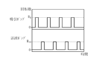
シャフト部20に対する低流量での吸引及び送液について、上述の実施形態では、図6(a)に示すように、吸引ポンプ53及び送液ポンプ54の両方とも、一定の回転数で運転している。一方、図6(b)に示すように、送液ポンプ54は一定の回転数で運転しつつ、吸引ポンプ53は、回転数R2’の間欠的な運転を行うようにしてもよい。これにより、患者の失血量を抑えたり、医療デバイス10内に滞留した血液または血栓を効率的に体外に排出することができる。
図7(a)に示すように、吸引ポンプ53の回転数をR2より小さいR7とし、送液ポンプ54の回転数をR5より大きいR8として、送液ポンプ54の方が吸引ポンプ53より大きい回転数となるようにしてもよい。この場合、吸引ポンプ53による吸引量より送液ポンプ54による送液量の方が大きくなり、血管内には生理食塩水が注入される。このため、血液を吸引する量を少なくし、処置における失血量を抑えることができる。また、吸引より送液が優先されることで、シャフト部20内における生理食塩水の濃度を高く、血液の濃度を低くできるため、シャフト部20内における血栓の発生をより抑えることができる。
また、図7(b)に示すように、吸引より送液を優先する場合において、吸引ポンプ53は一定の回転数で運転しつつ、送液ポンプ54は、回転数R8’の間欠的な運転を行うようにしてもよい。これにより、患者の体内に流れる生理食塩水の量を低減することができる。
図8に示すように、吸引ポンプ53が回転数R9の間欠的な運転を行い、送液ポンプ54も回転数R10の間欠的な運転を行うようにしてもよい。図8では、吸引ポンプ53と送液ポンプ54は、交互に動作しているが、同期させてもよいし、一定間隔ずらして動作させてもよい。これにより、患者の失血量を抑えながら、患者の体内に流れる生理食塩水の量を低減することができる。
本実施形態の医療デバイス10は、血管からの吸引や送液を行うため、処置においては、患者の失血量をコントロールすることが必要である。制御装置11は、そのための報知部や操作部を有していてもよい。例えば、医療デバイス10を生体内に挿入してからの時間や処置時間を計測し、一定の時間が経過したら音声または光で術者に通知を行う報知部を設けることができる。また、医療デバイス10を生体内に挿入してからの失血量を、吸引ポンプ53またはその近傍で計測し、失血量が一定の値を超えたら音声または光で通知を行う報知部を設けることができる。また、吸引ポンプ53またはその近傍で吸引量を計測し、その吸引量に応じて音声または光の強さを変化させる報知部を設けることができる。上記の通知を、処置時間、処置時間以外の吸引時間、失血量を液晶表示することで行ってもよいし、通知と同時に強制的に吸引や送液を停止させてもよい。このほかに、シャフト部20に対する低流量での吸引及び送液時に、制御装置11または筐体40が、音声(一定間隔のビープ音など)または光(点滅光など)を発するようにしてもよい。これにより、術者またはユーザに、シャフト部20に対して低流量での吸引及び送液が行われている事実を継続的に認識させることができる。上記の方法により、手技中の患者の失血量を低減することができる。
また、制御装置11または筐体40に吸引ポンプ53による吸引を一時的に停止させる一時停止操作部を設けてもよい。これにより、処置中に失血量を減らしたい場合などに、術者またはユーザが一時停止操作部を操作することで、簡単かつ即座に対応することができる。一時停止操作により吸引の一時停止が一定時間を経過したら、音声または光で通知させてもよいし、強制的に吸引や送液を再開させてもよい。これにより、術者またはユーザが一時停止操作を再開し忘れた場合も、血栓形成を回避できる。
上述の処置方法において、シャフト部20の血管への挿入状態をセンサ部70で検出することで、シャフト部20に対する低流量での吸引及び送液を行うために、図9に示すように、操作部22の筐体40内に、圧力センサからなるセンサ部70を設けることができる。センサ部70は、吸引ルーメン35と連通する位置に設けられる。シャフト部20が動脈内に挿入されると、逆血による血圧がシャフト部20の内部にかかる。この血圧をセンサ部70で検出することにより、シャフト部20が血管内に挿入されたことを検出できる。シャフト部20が血管内に挿入されたことをセンサ部70で検出したら、上述のように、流体制御部50は、シャフト部20に対する低流量での吸引及び送液を開始する。また、センサ部70において、血圧分の圧力低下を検出したら、シャフト部20が血管から抜去されたものとして、流体制御部50は、シャフト部20に対する低流量での吸引及び送液を停止する。
なお、圧力センサであるセンサ部70の配置位置は、図9の例には限られず、逆血による血圧を検出できる位置であればよい。また、図9では、吸引ルーメン35を介して血管からの血圧をセンサ部70で検出しているが、シャフト部20あるいは別のシャフト部材に圧力検出用のルーメンを別途設け、このルーメンを介してセンサ部70で圧力検出するようにしてもよい。
図10に示すように、センサ部71は、操作部22の外部に露出する押釦スイッチで形成してもよい。センサ部71は、操作部22が台あるいはホルダ等に置かれているか否かを検出することができる。センサ部71により、操作部22が台等に置かれていると検出された場合、医療デバイスは血管内に挿入されていないものとして、流体制御部50はシャフト部20に対する吸引及び送液を行わない。センサ部71により、操作部22が台等から離れたと検出された場合、医療デバイスは血管内に挿入されたものとして、流体制御部50はシャフト部20に対する吸引及び送液を開始する。
以上のように、本実施形態に係る医療デバイスの制御装置は、生体内に挿入され、先端部に生体管腔の物体を処置する処置部が設けられた長尺管状の医療デバイス10の制御装置11であって、医療デバイス10に接続される吸引源53または送液源54と、医療デバイス10の内部を流動する流体の流量を制御する制御部50と、を有し、制御部50は、医療デバイス10に吸引源53が接続されている場合、吸引源53を制御し、処置部21による処置時には、医療デバイス10の内部の流体を第1の流量で吸引させ、医療デバイス10が生体内に挿入されている間であって処置時以外の間、医療デバイス10の内部の流体を第1の流量より小さい第2の流量で吸引させること、または、医療デバイス10に送液源54が接続されている場合、送液源54を制御し、処置部21による処置時には、医療デバイス10の内部に流体を第3の流量で送液させ、医療デバイス10が生体内に挿入されている間であって処置時以外の間、医療デバイス10の内部に流体を第3の流量より小さい第4の流量で送液させること、のいずれかを行う。これにより、医療デバイス10が生体内に挿入されている間であって処置時以外の間にも、医療デバイス10の内部に流体が流動するので、医療デバイス10の内部において血栓の発生を抑制できる。
また、本実施形態に係る医療デバイス10の制御装置11は、生体内に挿入され、先端部に生体管腔の物体を処置する処置部21が設けられた長尺管状の医療デバイス10の制御装置11であって、医療デバイス10に接続される吸引源53と、医療デバイス10に接続される送液源54と、医療デバイス10の内部を流動する流体の流量を制御する制御部50と、を有し、制御部50は、医療デバイス10に吸引源53が接続されている場合、吸引源53を制御し、処置部21による処置時には、医療デバイス10の内部の流体を第1の流量で吸引させ、医療デバイス10が生体内に挿入されている間であって処置時以外の間、医療デバイス10の内部の流体を第1の流量より小さい第2の流量で吸引させ、かつ、医療デバイス10に送液源54が接続されている場合、送液源54を制御し、処置部21による処置時には、医療デバイス10の内部に流体を第3の流量で送液させ、医療デバイス10が生体内に挿入されている間であって処置時以外の間、医療デバイス10の内部に流体を第3の流量より小さい第4の流量で送液させる。これにより、医療デバイス10が生体内に挿入されている間であって処置時以外の間にも、医療デバイス10の内部に流体が流動するので、医療デバイス10の内部において血栓の発生を抑制できる。
また、制御部50は、第2の流量が第4の流量より大きくなるように、吸引源53及び送液源54を制御することができる。これにより、送液より吸引が優先され、駆動シャフト30に対するシール性を確保しつつ、医療デバイス10内の流体を流動させることができる。また、送液より吸引を優先することで、医療デバイス10内の血栓を血管内に押し出すことがないようにすることができる。
また、制御部50は、第4の流量が第2の流量より大きくなるように、吸引源53及び送液源54を制御することができる。これにより、吸引より送液が優先されるので、血液を吸引する量を少なくし、処置における失血量を抑えることができる。また、吸引より送液が優先されることで、医療デバイス10内における生理食塩水の濃度を高く、血液の濃度を低くできるため、医療デバイス10内における血栓の発生をより抑えることができる。
また、制御部50は、医療デバイス10に吸引源53が接続されている場合、医療デバイス10のプライミング時には、第2の流量より大きい流量で、吸引源53に吸引させるようにすることができる。これにより、医療デバイス10のプライミング時間を短縮しながら、処置時以外の間には、医療デバイス10の内部を低流量で流体を流動させることができる。
また、制御部50は、医療デバイス10に送液源54が接続されている場合、医療デバイス10のプライミング時には、第4の流量で、送液源54に送液させるようにすることができる。これにより、医療デバイス10のプライミング時間を短縮しながら、処置時以外の間には、医療デバイス10の内部を低流量で流体を流動させることができる。
また、制御部51は、医療デバイス10が生体内に挿入されている間であって処置時以外の間に、医療デバイス10を処置時より低速で回転させるようにすることができる。これにより、医療デバイス10の低速回転によって医療デバイス10内部の流体を流動させることができ、処置時以外の間における医療デバイス10内部の流体の流動を促進し、血栓形成を抑制することができる。
また、医療デバイス10の生体内に対する挿入状態を検出するセンサ部70をさらに有し、医療デバイス10に吸引源53が接続されている場合、制御部50は、センサ部70で医療デバイス10が生体内に挿入された状態であることを検出している間であって処置時以外の間、シャフト部20の内部の流体を第2の流量で流動させるようにすれば、医療デバイス10が生体内に挿入されている間、自動的に第2の流量にて流体を流動させることができる。
また、医療デバイス10の生体内に対する挿入状態を検出するセンサ部70をさらに有し、医療デバイス10に送液源54が接続されている場合、制御部50は、センサ部70で医療デバイス10が生体内に挿入された状態であることを検出している間であって処置時以外の間、医療デバイス10の内部の流体を第4の流量で流動させるようにすれば、医療デバイス10が生体内に挿入されている間、自動的に第4の流量にて流体を流動させることができる。
また、医療デバイス10に吸引源53が接続されている場合、制御部50が医療デバイス10の内部の流体を第2の流量で吸引させている際に、当該吸引を一時的に停止させる一時停止操作部をさらに有するようにすれば、処置中に失血量を減らしたい場合などに、術者またはユーザが一時停止操作部を操作することで、簡単かつ即座に対応することができる。
また、医療デバイス10に送液源54が接続されている場合、制御部50が医療デバイス10の内部に流体を第4の流量で送液させている際に、当該送液を一時的に停止させる一時停止操作部をさらに有するようにすれば、処置中に失血量を減らしたい場合などに、術者またはユーザが一時停止操作部を操作することで、簡単かつ即座に対応することができる。
また、医療デバイス10に吸引源53が接続されている場合、制御部50が医療デバイス10の内部の流体を第2の流量で吸引させていること、または、医療デバイス10に送液源54が接続されている場合、制御部50が医療デバイス10の内部に流体を第4の流量で送液させていることを音声または光で報知する報知部をさらに有するようにすれば、患者の失血量のコントロールに報知部を利用することができる。
また、本実施形態における医療デバイスシステムの制御方法は、生体内に挿入可能な長尺管状のシャフト部20と、シャフト部20の先端部に設けられる処置部21とを有する医療デバイス10と、シャフト部20の内部を流動する流体の流量を制御する流体制御部50と、を有する医療デバイスシステムの制御方法であって、流体制御部50は、シャフト部20を生体内に挿入して処置部21による処置を開始するまでの間、シャフト部20の内部に流体を一定の流量で流動させ、流体制御部50は、処置部21による処置を開始して終了するまでの間、シャフト部20の内部に流体を一定の流量より大きい流量で流動させ、流体制御部50は、処置部21による処置が終了してシャフト部20を生体から抜去するまでの間、シャフト部20の内部に流体を一定の流量で流動させる。これにより、シャフト部20が生体内に挿入されている間であって処置時以外の間にも、シャフト部20の内部に流体を流動させるので、シャフト部20の内部において血栓の発生を抑制できる。処置時以外の間における流体の流動は、ソフトウェアによる自動制御により実現してもよいし、医療デバイス10が体内にある状態をセンサにより検出して実現してもよいし、制御装置11または筐体40のいずれかまたは両方に操作部を設けて、術者やユーザによる操作により実現してもよい。
また、本実施形態における流体の流量を制御する方法は、先端部に処置部21が設けられる医療デバイス10に、医療デバイス10の内部に対して流体を送液する送液源54または流体を吸引する吸引源53を接続し、流体の流量を制御する制御部50を作動させ、医療デバイス10を停止させている間、送液源54または吸引源53に流体を一定の流量で流動させ、医療デバイス10を作動させている間、送液源54または吸引源53に流体を一定の流量より大きい流量で流動させる。これにより、医療デバイス10を停止させている間にも、送液源54または吸引源53に流体を一定の流量で流動させるので、医療デバイス10の内部において血栓の発生を抑制できる。
なお、本発明は、上述した実施形態のみに限定されるものではなく、本発明の技術的思想内において当業者により種々変更が可能である。例えば、上述の実施形態では、吸引ポンプ53で吸引を行い、送液ポンプ54で送液を行っているが、それ以外の手段で吸引や送液を行ってもよい。例えば、シリンジを用いて吸引や送液を行ってもよい。また、吸引については、血管内の血圧によって、血液がシャフト部20内を通じて外部に排出されるようにしてもよい。
また、上述の実施形態では、吸引ポンプ53や送液ポンプ54の回転数を流体制御部50が制御することにより、処置部21による処置が行われていない間の吸引量と送液量との差をコントロールしているが、それ以外の手段で吸引量と送液量との差をコントロールしてもよい。例えば、吸引ポンプ53と送液ポンプ54の回転数は同じで、吸引チューブ45と送液チューブ47の内径の大きさの差により、処置部21による処置が行われていない間の吸引量と送液量との差をコントロールしてもよい。また、単位時間当たりの流体排出量が異なる吸引ポンプ53および送液ポンプ54により、吸引量と送液量との差をコントロールしてもよい。また、これらの組み合わせであってもよい。
また、処置部21による処置が行われていない間において、駆動シャフト30を低速で回転させるようにしてもよい。駆動シャフト30は、一定の巻き方向を有するコイル状の管状体として形成することができる。この場合に、駆動シャフト30を一方に回転させることにより、駆動シャフト30の周囲に一方向に向かう軸方向流を生じさせることができる。これを利用し、シャフト部20が生体内に挿入されている間であって処置部21による処置時以外の間に、駆動シャフト30を処置時より低速で一方向に回転させ、シャフト部20内に吸引方向の流れを生じさせて、吸引による流体の移動をより促進させることができる。また、駆動シャフト30を前述の一方向と反対方向に回転させることで、シャフト部20内に送液方向の流れを生じさせて、送液による流体の移動をより促進させることもできる。さらに、駆動シャフト30の一方向への回転と反対方向への回転とを一定の周期で交互に行うようにしてもよい。これにより、シャフト部20内に吸引方向の流れと送液方向の流れを交互に生じさせることができる。
また、上述の実施形態において流体制御部50は、シャフト部20に対して吸引及び送液の両方を行っているが、吸引と送液のいずれか一方を行うようにしてもよい。また、上述の実施形態においてシャフト部20は、駆動シャフト30を有すると共に、吸引ルーメン35と送液ルーメン34とを有しているが、吸引または送液に使用する1つのルーメンのみ有するものであってもよい。また、シャフト部20は、吸引ルーメン35と送液ルーメン34とを有し、駆動シャフト30を有しないものであってもよい。また、上述の実施形態において、血栓抑制の対象はシャフト部20に限定されない。筐体40内及び吸引チューブ45においても、流体の流動を生じさせることで、血栓形成を抑制できる。医療デバイスは、上述の実施形態のようなアテレクトミーデバイス以外であっても、本発明を適用することができる。
なお、本出願は、2018年3月29日に出願された日本特許出願番号2018-064009号に基づいており、それらの開示内容は、参照され、全体として、組み入れられている。
10 医療デバイス
11 制御装置
20 シャフト部
21 処置部
21a 切削部
21b 軸受部
22 操作部
30 駆動シャフト
31 外側シース
32 内側シース
33 ガイドワイヤルーメン
34 送液ルーメン
35 吸引ルーメン
40 筐体
41 回転スイッチ
42 外側シース保持部
42a シール部
43 内側シース保持部
44 吸引口
45 吸引チューブ
46 送液口
47 送液チューブ
48 駆動シャフト保持部
48a シール部
49 回転モーター
50 流体制御部
51 入出力部
52 駆動制御部
53 吸引ポンプ
54 送液ポンプ
55 電源部
56 プライミングスイッチ
57 表示部
58 気泡検出器
60 流体源
11 制御装置
20 シャフト部
21 処置部
21a 切削部
21b 軸受部
22 操作部
30 駆動シャフト
31 外側シース
32 内側シース
33 ガイドワイヤルーメン
34 送液ルーメン
35 吸引ルーメン
40 筐体
41 回転スイッチ
42 外側シース保持部
42a シール部
43 内側シース保持部
44 吸引口
45 吸引チューブ
46 送液口
47 送液チューブ
48 駆動シャフト保持部
48a シール部
49 回転モーター
50 流体制御部
51 入出力部
52 駆動制御部
53 吸引ポンプ
54 送液ポンプ
55 電源部
56 プライミングスイッチ
57 表示部
58 気泡検出器
60 流体源
Claims (13)
- 生体内に挿入され、先端部に生体管腔の物体を処置する処置部が設けられた長尺管状の医療デバイスの制御装置であって、
前記医療デバイスに接続される吸引源または送液源と、
前記医療デバイスの内部を流動する流体の流量を制御する制御部と、を有し、
前記制御部は、
(1)前記医療デバイスに前記吸引源が接続されている場合には、前記吸引源を制御し、前記処置部による処置時には、前記医療デバイスの内部の流体を第1の流量で吸引させ、前記医療デバイスが生体内に挿入されている間であって前記処置時以外の間、前記医療デバイスの内部の流体を前記第1の流量より小さい第2の流量で吸引させ、または、
(2)前記医療デバイスに前記送液源が接続されている場合には、前記送液源を制御し、前記処置部による処置時には、前記医療デバイスの内部に流体を第3の流量で送液させ、前記医療デバイスが生体内に挿入されている間であって前記処置時以外の間、前記医療デバイスの内部に流体を前記第3の流量より小さい第4の流量で送液させる制御装置。 - 生体内に挿入され、先端部に生体管腔の物体を処置する処置部が設けられた長尺管状の医療デバイスの制御装置であって、
前記医療デバイスに接続される吸引源と、
前記医療デバイスに接続される送液源と、
前記医療デバイスの内部を流動する流体の流量を制御する制御部と、を有し、
前記制御部は、
(1)前記吸引源を制御し、前記処置部による処置時には、前記医療デバイスの内部の流体を第1の流量で吸引させ、前記医療デバイスが生体内に挿入されている間であって前記処置時以外の間、前記医療デバイスの内部の流体を前記第1の流量より小さい第2の流量で吸引させ、かつ、
(2)前記送液源を制御し、前記処置部による処置時には、前記医療デバイスの内部に流体を第3の流量で送液させ、前記医療デバイスが生体内に挿入されている間であって前記処置時以外の間、前記医療デバイスの内部に流体を前記第3の流量より小さい第4の流量で送液させる制御装置。 - 前記制御部は、前記第2の流量が前記第4の流量より大きくなるように、前記吸引源及び送液源を制御する請求項2に記載の制御装置。
- 前記制御部は、前記第4の流量が前記第2の流量より大きくなるように、前記吸引源及び送液源を制御する請求項2に記載の制御装置。
- 前記制御部は、前記医療デバイスに前記吸引源が接続されている場合、前記医療デバイスのプライミング時には、前記第2の流量より大きい流量で、前記吸引源に吸引させる請求項1~4のいずれか1項に記載の制御装置。
- 前記制御部は、前記医療デバイスに前記送液源が接続されている場合、前記医療デバイスのプライミング時には、前記第4の流量より大きい流量で、前記送液源に送液させる請求項1~4のいずれか1項に記載の制御装置。
- 前記制御部は、前記医療デバイスが生体内に挿入されている間であって前記処置時以外の間、前記医療デバイスを前記処置時より低速で回転させる請求項1~6のいずれか1項に記載の制御装置。
- 前記医療デバイスの生体内に対する挿入状態を検出するセンサ部をさらに有し、
前記医療デバイスに前記吸引源が接続されている場合、前記制御部は、前記センサ部で前記医療デバイスが生体内に挿入された状態であることを検出している間であって前記処置時以外の間、前記医療デバイスの内部の流体を前記第2の流量で流動させる請求項1~7のいずれか1項に記載の制御装置。 - 前記医療デバイスの生体内に対する挿入状態を検出するセンサ部をさらに有し、
前記医療デバイスに前記送液源が接続されている場合、前記制御部は、前記センサ部で前記医療デバイスが生体内に挿入された状態であることを検出している間であって前記処置時以外の間、前記医療デバイスの内部の流体を前記第4の流量で流動させる請求項1~7のいずれか1項に記載の制御装置。 - 前記医療デバイスに前記吸引源が接続されている場合、前記制御部が前記医療デバイスの内部の流体を前記第2の流量で吸引させている際に、当該吸引を一時的に停止させる一時停止操作部をさらに有する請求項1~7のいずれか1項に記載の制御装置。
- 前記医療デバイスに前記送液源が接続されている場合、前記制御部が前記医療デバイスの内部に流体を前記第4の流量で送液させている際に、当該送液を一時的に停止させる一時停止操作部をさらに有する請求項1~7のいずれか1項に記載の制御装置。
- 前記医療デバイスに前記吸引源が接続されている場合、前記制御部が前記医療デバイスの内部の流体を前記第2の流量で吸引させていること、または、前記医療デバイスに前記送液源が接続されている場合、前記制御部が前記医療デバイスの内部に流体を前記第4の流量で送液させていることを、音声または光で報知する報知部をさらに有する請求項1~11のいずれか1項に記載の制御装置。
- 流体の流量を制御する方法であって、
先端部に処置部が設けられる医療デバイスに、該医療デバイスの内部に対して流体を送液する送液源または流体を吸引する吸引源を接続し、
流体の流量を制御する制御部を作動させ、前記医療デバイスを停止させている間、前記送液源または吸引源に流体を一定の流量で流動させ、
前記医療デバイスを作動させている間、前記送液源または吸引源に流体を前記一定の流量より大きい流量で流動させる方法。
Priority Applications (2)
| Application Number | Priority Date | Filing Date | Title |
|---|---|---|---|
| JP2020510780A JP7241064B2 (ja) | 2018-03-29 | 2019-03-20 | 医療デバイスの制御装置及び流体の流量を制御する方法 |
| US17/009,910 US20200397465A1 (en) | 2018-03-29 | 2020-09-02 | Control apparatus for medical device and method of controlling flow rate of fluid |
Applications Claiming Priority (2)
| Application Number | Priority Date | Filing Date | Title |
|---|---|---|---|
| JP2018064009 | 2018-03-29 | ||
| JP2018-064009 | 2018-03-29 |
Related Child Applications (1)
| Application Number | Title | Priority Date | Filing Date |
|---|---|---|---|
| US17/009,910 Continuation US20200397465A1 (en) | 2018-03-29 | 2020-09-02 | Control apparatus for medical device and method of controlling flow rate of fluid |
Publications (1)
| Publication Number | Publication Date |
|---|---|
| WO2019188656A1 true WO2019188656A1 (ja) | 2019-10-03 |
Family
ID=68058144
Family Applications (1)
| Application Number | Title | Priority Date | Filing Date |
|---|---|---|---|
| PCT/JP2019/011689 Ceased WO2019188656A1 (ja) | 2018-03-29 | 2019-03-20 | 医療デバイスの制御装置及び流体の流量を制御する方法 |
Country Status (3)
| Country | Link |
|---|---|
| US (1) | US20200397465A1 (ja) |
| JP (1) | JP7241064B2 (ja) |
| WO (1) | WO2019188656A1 (ja) |
Cited By (3)
| Publication number | Priority date | Publication date | Assignee | Title |
|---|---|---|---|---|
| WO2021199210A1 (ja) * | 2020-03-30 | 2021-10-07 | テルモ株式会社 | 医療デバイス |
| EP4209191A1 (en) * | 2020-01-17 | 2023-07-12 | Axon Therapies, Inc. | Catheter and computer for calculation of accumulated volume of liquid delivered into a patient |
| US12349966B2 (en) | 2019-06-20 | 2025-07-08 | Axon Therapies, Inc. | Methods and devices for endovascular ablation of a splanchnic nerve |
Families Citing this family (6)
| Publication number | Priority date | Publication date | Assignee | Title |
|---|---|---|---|---|
| US10716880B2 (en) * | 2018-06-15 | 2020-07-21 | Incuvate, Llc | Systems and methods for aspiration and monitoring |
| CN110141303B (zh) * | 2019-06-06 | 2022-09-02 | 赛诺神畅医疗科技有限公司 | 用于碎栓并抽吸血栓的器械 |
| EP4329643A4 (en) | 2021-04-27 | 2025-03-12 | Contego Medical, Inc. | Thrombus aspiration system and methods for controlling blood loss |
| US12551609B2 (en) * | 2021-10-04 | 2026-02-17 | Olympus Medical Systems Corp. | Medical solid-matter collection apparatus and medical suction system |
| US12280222B2 (en) | 2023-08-28 | 2025-04-22 | Incuvate, Llc | Systems and methods for injection and aspiration |
| US12544500B2 (en) | 2023-08-28 | 2026-02-10 | Incuvate, Llc | Systems and methods for injection and aspiration |
Citations (4)
| Publication number | Priority date | Publication date | Assignee | Title |
|---|---|---|---|---|
| JPS6340541A (ja) * | 1986-06-09 | 1988-02-20 | ザ・リ−ジエンツ・オブ・ザ・ユニバ−シテイ・オブ・カリフオルニア | 生体器官或は腔内の障害物を除去する為の装置 |
| JP2011500151A (ja) * | 2007-10-12 | 2011-01-06 | ザ スペクトラネティックス コーポレイション | 血栓切除および軟質残屑物を除去する装置 |
| JP2013154171A (ja) * | 2012-01-26 | 2013-08-15 | Covidien Lp | 血栓摘出カテーテルシステム |
| JP2016156608A (ja) * | 2015-01-28 | 2016-09-01 | ゼネラル エレクトリック テクノロジー ゲゼルシャフト ミット ベシュレンクテル ハフツングGeneral Electric Technology GmbH | 混合器を備えた2段燃焼器配列 |
Family Cites Families (7)
| Publication number | Priority date | Publication date | Assignee | Title |
|---|---|---|---|---|
| US5213571A (en) * | 1989-07-27 | 1993-05-25 | Olympus Optical Co., Ltd. | Litholysis apparatus provided with safe stop function |
| US5395312A (en) * | 1991-10-18 | 1995-03-07 | Desai; Ashvin | Surgical tool |
| US5417703A (en) * | 1993-07-13 | 1995-05-23 | Scimed Life Systems, Inc. | Thrombectomy devices and methods of using same |
| US9474848B2 (en) * | 2009-03-09 | 2016-10-25 | Thermedx, Llc | Fluid management system |
| EP2695632A1 (en) | 2012-08-10 | 2014-02-12 | Irras AB | Fluid exchange catheter and process for unblocking a fluid exchange catheter |
| US10052122B2 (en) * | 2014-01-17 | 2018-08-21 | Cardiovascular Systems, Inc. | Spin-to-open atherectomy device with electric motor control |
| US11160602B2 (en) * | 2017-08-29 | 2021-11-02 | Cilag Gmbh International | Control of surgical field irrigation |
-
2019
- 2019-03-20 JP JP2020510780A patent/JP7241064B2/ja active Active
- 2019-03-20 WO PCT/JP2019/011689 patent/WO2019188656A1/ja not_active Ceased
-
2020
- 2020-09-02 US US17/009,910 patent/US20200397465A1/en active Pending
Patent Citations (4)
| Publication number | Priority date | Publication date | Assignee | Title |
|---|---|---|---|---|
| JPS6340541A (ja) * | 1986-06-09 | 1988-02-20 | ザ・リ−ジエンツ・オブ・ザ・ユニバ−シテイ・オブ・カリフオルニア | 生体器官或は腔内の障害物を除去する為の装置 |
| JP2011500151A (ja) * | 2007-10-12 | 2011-01-06 | ザ スペクトラネティックス コーポレイション | 血栓切除および軟質残屑物を除去する装置 |
| JP2013154171A (ja) * | 2012-01-26 | 2013-08-15 | Covidien Lp | 血栓摘出カテーテルシステム |
| JP2016156608A (ja) * | 2015-01-28 | 2016-09-01 | ゼネラル エレクトリック テクノロジー ゲゼルシャフト ミット ベシュレンクテル ハフツングGeneral Electric Technology GmbH | 混合器を備えた2段燃焼器配列 |
Cited By (4)
| Publication number | Priority date | Publication date | Assignee | Title |
|---|---|---|---|---|
| US12349966B2 (en) | 2019-06-20 | 2025-07-08 | Axon Therapies, Inc. | Methods and devices for endovascular ablation of a splanchnic nerve |
| EP4209191A1 (en) * | 2020-01-17 | 2023-07-12 | Axon Therapies, Inc. | Catheter and computer for calculation of accumulated volume of liquid delivered into a patient |
| WO2021199210A1 (ja) * | 2020-03-30 | 2021-10-07 | テルモ株式会社 | 医療デバイス |
| US12484928B2 (en) | 2020-03-30 | 2025-12-02 | Terumo Kabushiki Kaisha | Medical device |
Also Published As
| Publication number | Publication date |
|---|---|
| US20200397465A1 (en) | 2020-12-24 |
| JPWO2019188656A1 (ja) | 2021-04-01 |
| JP7241064B2 (ja) | 2023-03-16 |
Similar Documents
| Publication | Publication Date | Title |
|---|---|---|
| JP7241064B2 (ja) | 医療デバイスの制御装置及び流体の流量を制御する方法 | |
| US11490911B2 (en) | Catheter assembly for blood clot removal | |
| US11771445B2 (en) | Aspiration monitoring system and method | |
| US7174240B2 (en) | Control system for rotational angioplasty device | |
| US7842009B2 (en) | Interventional catheters incorporating aspiration and/or infusion systems | |
| JP5284344B2 (ja) | 血栓摘出システムのための方法および装置 | |
| CN112384150A (zh) | 抽吸及监控的系统和方法 | |
| CN107920748A (zh) | 抽吸监控系统和方法 | |
| TW201517890A (zh) | 眼科潤滑系統及相關設備、系統及方法 | |
| JPH07108296B2 (ja) | 生体器官或は腔内の障害物を除去する為の装置 | |
| US12053193B2 (en) | Aspiration pump for removal of fluids, blood clots and other materials from human body | |
| WO2014033781A1 (ja) | 制御装置、循環装置及び制御方法 | |
| JP2013150711A (ja) | 瘤治療デバイス及び瘤治療方法 | |
| JP3544185B2 (ja) | 携帯式治療ユニット | |
| WO2014162358A1 (ja) | 体外循環装置 | |
| JP2024534512A (ja) | 眼科手術システムを操作するための方法、及び眼科手術システム | |
| KR20250171289A (ko) | 심실 보조 시스템, 의료용 카테터 펌프 시스템의 플러싱 방법, 소모품 및 장치 | |
| WO2025049600A1 (en) | Systems and methods for injection and aspiration | |
| JP2014200356A (ja) | 治療用デバイスおよびその使用方法 | |
| JP2015196026A (ja) | 血流障害の治療方法、治療装置および治療システム |
Legal Events
| Date | Code | Title | Description |
|---|---|---|---|
| 121 | Ep: the epo has been informed by wipo that ep was designated in this application |
Ref document number: 19775148 Country of ref document: EP Kind code of ref document: A1 |
|
| ENP | Entry into the national phase |
Ref document number: 2020510780 Country of ref document: JP Kind code of ref document: A |
|
| NENP | Non-entry into the national phase |
Ref country code: DE |
|
| 122 | Ep: pct application non-entry in european phase |
Ref document number: 19775148 Country of ref document: EP Kind code of ref document: A1 |