WO2019188232A1 - コネクタ、及びコネクタ付き機器 - Google Patents
コネクタ、及びコネクタ付き機器 Download PDFInfo
- Publication number
- WO2019188232A1 WO2019188232A1 PCT/JP2019/009868 JP2019009868W WO2019188232A1 WO 2019188232 A1 WO2019188232 A1 WO 2019188232A1 JP 2019009868 W JP2019009868 W JP 2019009868W WO 2019188232 A1 WO2019188232 A1 WO 2019188232A1
- Authority
- WO
- WIPO (PCT)
- Prior art keywords
- connector
- valve body
- peripheral surface
- outer peripheral
- along
- Prior art date
- Legal status (The legal status is an assumption and is not a legal conclusion. Google has not performed a legal analysis and makes no representation as to the accuracy of the status listed.)
- Ceased
Links
Images

Classifications
-
- H—ELECTRICITY
- H01—ELECTRIC ELEMENTS
- H01R—ELECTRICALLY-CONDUCTIVE CONNECTIONS; STRUCTURAL ASSOCIATIONS OF A PLURALITY OF MUTUALLY-INSULATED ELECTRICAL CONNECTING ELEMENTS; COUPLING DEVICES; CURRENT COLLECTORS
- H01R13/00—Details of coupling devices of the kinds covered by groups H01R12/70 or H01R24/00 - H01R33/00
- H01R13/648—Protective earth or shield arrangements on coupling devices, e.g. anti-static shielding
- H01R13/658—High frequency shielding arrangements, e.g. against EMI [Electro-Magnetic Interference] or EMP [Electro-Magnetic Pulse]
- H01R13/6581—Shield structure
-
- H—ELECTRICITY
- H01—ELECTRIC ELEMENTS
- H01R—ELECTRICALLY-CONDUCTIVE CONNECTIONS; STRUCTURAL ASSOCIATIONS OF A PLURALITY OF MUTUALLY-INSULATED ELECTRICAL CONNECTING ELEMENTS; COUPLING DEVICES; CURRENT COLLECTORS
- H01R13/00—Details of coupling devices of the kinds covered by groups H01R12/70 or H01R24/00 - H01R33/00
- H01R13/46—Bases; Cases
- H01R13/516—Means for holding or embracing insulating body, e.g. casing, hoods
- H01R13/518—Means for holding or embracing insulating body, e.g. casing, hoods for holding or embracing several coupling parts, e.g. frames
-
- H—ELECTRICITY
- H01—ELECTRIC ELEMENTS
- H01R—ELECTRICALLY-CONDUCTIVE CONNECTIONS; STRUCTURAL ASSOCIATIONS OF A PLURALITY OF MUTUALLY-INSULATED ELECTRICAL CONNECTING ELEMENTS; COUPLING DEVICES; CURRENT COLLECTORS
- H01R13/00—Details of coupling devices of the kinds covered by groups H01R12/70 or H01R24/00 - H01R33/00
- H01R13/62—Means for facilitating engagement or disengagement of coupling parts or for holding them in engagement
- H01R13/639—Additional means for holding or locking coupling parts together, after engagement, e.g. separate keylock, retainer strap
-
- H—ELECTRICITY
- H01—ELECTRIC ELEMENTS
- H01R—ELECTRICALLY-CONDUCTIVE CONNECTIONS; STRUCTURAL ASSOCIATIONS OF A PLURALITY OF MUTUALLY-INSULATED ELECTRICAL CONNECTING ELEMENTS; COUPLING DEVICES; CURRENT COLLECTORS
- H01R13/00—Details of coupling devices of the kinds covered by groups H01R12/70 or H01R24/00 - H01R33/00
- H01R13/64—Means for preventing incorrect coupling
-
- F—MECHANICAL ENGINEERING; LIGHTING; HEATING; WEAPONS; BLASTING
- F16—ENGINEERING ELEMENTS AND UNITS; GENERAL MEASURES FOR PRODUCING AND MAINTAINING EFFECTIVE FUNCTIONING OF MACHINES OR INSTALLATIONS; THERMAL INSULATION IN GENERAL
- F16H—GEARING
- F16H61/00—Control functions within control units of change-speed- or reversing-gearings for conveying rotary motion ; Control of exclusively fluid gearing, friction gearing, gearings with endless flexible members or other particular types of gearing
- F16H61/0003—Arrangement or mounting of elements of the control apparatus, e.g. valve assemblies or snapfittings of valves; Arrangements of the control unit on or in the transmission gearbox
- F16H61/0006—Electronic control units for transmission control, e.g. connectors, casings or circuit boards
-
- H—ELECTRICITY
- H01—ELECTRIC ELEMENTS
- H01R—ELECTRICALLY-CONDUCTIVE CONNECTIONS; STRUCTURAL ASSOCIATIONS OF A PLURALITY OF MUTUALLY-INSULATED ELECTRICAL CONNECTING ELEMENTS; COUPLING DEVICES; CURRENT COLLECTORS
- H01R13/00—Details of coupling devices of the kinds covered by groups H01R12/70 or H01R24/00 - H01R33/00
- H01R13/62—Means for facilitating engagement or disengagement of coupling parts or for holding them in engagement
- H01R13/627—Snap or like fastening
- H01R13/6271—Latching means integral with the housing
- H01R13/6272—Latching means integral with the housing comprising a single latching arm
-
- H—ELECTRICITY
- H01—ELECTRIC ELEMENTS
- H01R—ELECTRICALLY-CONDUCTIVE CONNECTIONS; STRUCTURAL ASSOCIATIONS OF A PLURALITY OF MUTUALLY-INSULATED ELECTRICAL CONNECTING ELEMENTS; COUPLING DEVICES; CURRENT COLLECTORS
- H01R2103/00—Two poles
-
- H—ELECTRICITY
- H01—ELECTRIC ELEMENTS
- H01R—ELECTRICALLY-CONDUCTIVE CONNECTIONS; STRUCTURAL ASSOCIATIONS OF A PLURALITY OF MUTUALLY-INSULATED ELECTRICAL CONNECTING ELEMENTS; COUPLING DEVICES; CURRENT COLLECTORS
- H01R24/00—Two-part coupling devices, or either of their cooperating parts, characterised by their overall structure
- H01R24/66—Two-part coupling devices, or either of their cooperating parts, characterised by their overall structure with pins, blades or analogous contacts and secured to apparatus or structure, e.g. to a wall
Definitions
- the present invention relates to a connector attached to a device having a cylindrical shape, and a device with a connector including the connector.
- a device connector described in Patent Document 1 is shown as a device connector used by being attached to a device disposed in an automatic transmission of a vehicle.
- a connector housing protrudes from the outer peripheral surface of a cylindrical device.
- the connector housing has a hood portion, and terminals that are electrically connected to the device protrude from the hood portion.
- arranged inside is mentioned, for example.
- a lock hole for locking the mating connector is provided at a position above the terminal so as to penetrate the upper wall of the device connector.
- the locking portion of the counterpart connector is elastically fitted into the lock hole, so that the counterpart connector and the device connector are held in a fitted state.
- the lock hole is arranged above the terminal, so that there is a problem that the device connector is enlarged upward.
- the technology disclosed in the present specification has been completed based on the above circumstances, and an object thereof is to provide a technology relating to a reduction in the height of a connector.
- the technology disclosed in the present specification is a connector disposed on an outer peripheral surface of a cylindrical device, the leg projecting outward in the radial direction of the device, and the device from the tip of the leg A plurality of terminals formed along the outer peripheral surface of the device and embedded in the leg portion, and formed along the outer peripheral surface of the device. And a locking portion that is disposed between the plurality of terminals and that locks the counterpart connector.
- locking part is distribute
- the leg portion is provided at a central position of the hood portion in a direction along the outer peripheral surface of the device.
- the force received by the hood portion from the mating connector can be equally received by the leg portion in the direction along the outer peripheral surface of the device.
- the other party connector is fitted, it is possible to suppress the force in the direction in which the hood portion is twisted about the leg portion as an axis.
- the locking portion is provided at a central position of the hood portion in a direction along the outer peripheral surface of the device.
- the height of the connector can be further reduced.
- the technology disclosed in the present specification includes a cylindrical device extending along an axial direction, a connector disposed on an outer peripheral surface of the device, an outer portion of the device, and one end portion.
- a metal magnetic shield member having a cylindrical shape with an opening, and a connector-equipped device, wherein the magnetic shield member is formed in a concave shape from the opening end of the one end portion, and the leg portion It has an avoidance recess that avoids interference.
- the leg portion protruding from the side wall of the device provides a gap between the device and the hood portion, and the magnetic shield member is inserted into this gap.
- a portion of the device that is not covered with the magnetic shield member is an area where the magnetic shield member is provided with an avoidance recess.
- the device has a front wall located on the front side in the axial direction and a rear wall located on the rear side, and the magnetic shield member includes a front shield portion along the front wall of the device, and the device.
- a side shield part extending along the side wall of the side shield part, and an end part of the side shield part is bent along the rear wall to be a bent part connected to the side shield part.
- the rear wall of the device is covered with the bent portion.
- the height of the connector can be reduced.
- Embodiment 1 in which the technology disclosed in the present specification is applied to a solenoid 10 (an example of a device with a connector) disposed inside an automatic transmission (not shown) mounted on a vehicle (not shown). This will be described with reference to FIGS. In the following description, it is assumed that the Z direction is upward, the Y direction is front, and the X direction is left.
- valve body 11 As shown in FIGS. 3 and 4, the valve body 11 (an example of a device) has a cylindrical shape that extends in the front-rear direction (an example of an axial direction). A front wall is provided at the front end of the valve body 11, and a rear wall 13 is provided at the rear end of the valve body 11. The side wall 14 and the front wall of the valve body 11 are orthogonal to each other, and the side wall 14 and the rear wall 13 of the valve body 11 are orthogonal to each other.
- a coil (not shown) is accommodated in the valve body 11.
- the rear wall 13 of the valve body 11 is provided with a valve portion 15 that protrudes rearward.
- the valve portion 15 has a cylindrical shape with a smaller diameter than the valve body 11.
- a connector 16 is provided on the side wall 14 of the valve body 11 so as to protrude upward from a position near the rear end.
- the connector 16 has leg portions 17 that protrude outward from the side wall 14 of the valve body 11 in the radial direction of the valve body 11 with an interval in the circumferential direction of the valve body 11.
- a hood 18 is formed integrally with the leg 17 at the end of the leg 17 opposite to the valve body 11.
- the hood part 18 is opened forward, and a mating connector (not shown) can be fitted from the front.
- the leg portion 17 and the hood portion 18 are formed by injection molding an insulating synthetic resin.
- a gap 19 is formed by the leg portion 17 between the side wall 14 of the valve body 11 and the hood portion 18.
- the leg portion 17 is provided at the center position of the hood portion 18 in the direction along the outer peripheral surface of the valve body 11 when viewed from the front.
- the central position of the hood portion 18 in the direction along the outer peripheral surface of the valve body 11 may be a completely central position, or an area that is substantially recognized as the central position even if it is not the central position. May be.
- a plurality (two in this embodiment) of terminals 21 are arranged inside the hood portion 18.
- a portion of the terminal 21 disposed in the hood portion 18 is formed in a tab shape extending forward.
- the terminal 21 is made of a conductive metal and has a rod shape.
- the metal which comprises the terminal 21 can select suitably arbitrary metals as needed, such as copper and a copper alloy.
- a plating layer made of a metal such as tin or nickel may be formed on the surface of the terminal 21.
- the rear end portion of the terminal 21 is embedded in the rear wall 33 of the hood portion 18. Although not shown in detail, the rear end portion of the terminal 21 is bent in a direction approaching each other in the rear wall 33 of the hood portion 18 and is bent inward in the radial direction of the valve body 11. Are electrically connected to the coil in the valve body 11.
- the terminal 21 includes a first terminal 21A located on the left side and a second terminal 21B located on the right side.
- the first terminal 21 ⁇ / b> A protrudes outward in the radial direction of the valve body 11 from the side wall 14 of the valve body 11, bends in the clockwise direction when viewed from the front, and then bends forward.
- the second terminal 21B protrudes from the side wall 14 of the valve body 11 outward in the radial direction of the valve body 11, then bends counterclockwise as viewed from the rear, and then bends forward.
- the first terminal 21 ⁇ / b> A and the second terminal 21 ⁇ / b> B protrude from the side wall 14 of the valve body 11 and then bend in a direction away from each other along the circumferential direction of the valve body 11.
- a locking portion 24 is formed at a position between the first terminal 21 ⁇ / b> A and the second terminal 21 ⁇ / b> B, as viewed from the front, on the upper wall of the hood portion 18.
- the locking portion 24 and the lock receiving portion formed on the locking portion 24 are elastically locked, so that the mating connector fitted in the hood portion 18 is held in a retaining state. .
- the tab-shaped terminal 21 of the connector 16 and the female terminal (not shown) of the mating connector are electrically connected.
- the locking portion 24, the front end portion of the first terminal 21 ⁇ / b> A, and the front end portion of the second terminal 21 ⁇ / b> B are arranged on the outer peripheral surface of the side wall 14 of the valve body 11 along the circumferential direction of the valve body 11. They are arranged side by side along the space.
- the locking portion 24 is provided at the center position of the hood portion 18 in the direction along the outer peripheral surface of the valve body 11 when viewed from the front.
- the central position of the hood portion 18 in the direction along the outer peripheral surface of the valve body 11 may be a completely central position, or an area that is substantially recognized as the central position even if it is not the central position. May be.
- Magnetic shield member 26 As shown in FIG. 3, a metal magnetic shield member 26 is attached to the outside of the valve body 11 from the front. As a metal constituting the magnetic shield member 26, any metal such as copper, copper alloy, iron, iron alloy, or the like can be appropriately selected as necessary.
- the magnetic shield member 26 has a cylindrical shape that extends in the front-rear direction and is closed on the front side and opened on the rear side.
- the inner diameter dimension of the magnetic shield member 26 is set to be substantially the same as the outer dimension of the valve body 11.
- the opening end 34 of the magnetic shield member 26 is provided with an avoidance recess 27 that is concave toward the front.
- the avoidance recess 27 is provided at a position corresponding to the leg portion 17 of the connector 16 in a state where the magnetic shield member 26 is externally fitted to the valve body 11.
- the width dimension of the avoiding recess 27 in the left-right direction is set to be the same as or slightly larger than the width dimension of the leg portion 17 in the left-right direction.
- a side shield portion 32 of the magnetic shield member 26, which will be described later, is also disposed in the gap 19 between the hood portion 18 and the valve body 11.
- the region near the opening end 34 in the side wall 14 of the magnetic shield member 26 is bent inward in the radial direction of the valve body 11 to be a bent portion 29 along the rear wall 13 of the valve body 11.
- the lower end edge of the bent portion 29 is set at a position where it does not interfere with the valve portion 15.
- the magnetic shield member 26 has the front shield part 31 positioned in front of the front wall of the valve body 11 and the side wall 14 of the valve body 11 from the outside in the radial direction of the valve body 11 in a state where the valve body 11 is externally fitted. And a side shield part 32 for covering.
- the bent portion 29 is bent along the rear wall 13 of the valve body 11 and continues to the side shield portion 32.
- All areas of the front wall of the valve body 11 are covered with the front shield part 31.
- the side wall 14 of the valve body 11 is covered with a side shield portion 32 except for a region corresponding to the avoidance recess 27 of the magnetic shield member 26.
- the side wall 14 of the valve body 11 is exposed to the outside.
- a part of the rear wall 13 of the valve body 11 is covered with a bent portion 29 of the magnetic shield member 26.
- the front side of the valve body 11 is magnetically shielded by the front shield part 31, and the side of the valve body 11 is magnetically shielded by the side shield part 32 except for the region corresponding to the avoidance recess 27.
- the area corresponding to the bent portion 29 is magnetically shielded behind the valve body 11.
- the first terminal 21A and the second terminal 21B are formed in a predetermined shape by pressing a metal bar.
- the connector 16 is formed integrally with the valve body 11 by insert molding with an insulating synthetic resin.
- the magnetic shield member 26 is formed by pressing a metal plate material into a predetermined shape.
- the magnetic shield member 26 is fitted from the front of the valve body 11. At this time, the legs 17 are arranged inside the avoidance recess 27 of the magnetic shield member 26.
- the bent portion 29 is formed by bending the rear end edge of the magnetic shield member 26 inward in the radial direction of the valve body 11. Thereby, the solenoid 10 is completed.
- the present embodiment is a connector 16 disposed on the outer peripheral surface of a cylindrical valve body 11, and includes a leg portion 17 projecting outward in the radial direction of the valve body 11, and a valve body from the tip end portion of the leg portion 17. 1 is formed along the outer peripheral surface of 1, and is embedded in the hood portion 18 that can be fitted into the mating connector and the leg portion 17, and is disposed along the outer peripheral surface of the valve body 11 in the hood portion 18.
- a plurality of terminals 21A, 21B and a locking portion 24 for locking the mating connector are provided between the plurality of terminals 21A, 21B.
- locking part 24 is distribute
- the leg portion 17 is provided at the center position of the hood portion 18 in the direction along the outer peripheral surface of the valve body 11.
- the locking portion 24 is provided at the center position of the hood portion 18 in the direction along the outer peripheral surface of the valve body 11.
- the height of the connector 16 can be further reduced.
- the solenoid 10 is attached to the outside of the valve body 11, the valve body 11 having a cylindrical shape extending along the axial direction, the connector 16 disposed on the outer peripheral surface of the valve body 11, A solenoid 10 having a cylindrical metal shield member 26 with one end opened, and the magnetic shield member 26 is formed in a concave shape from the open end 34 of one end and is a leg. An avoidance recess 27 for avoiding interference with the portion 17 is provided.
- the gap 17 is provided between the valve body 11 and the hood portion 18 by the leg portion 17 protruding from the side wall of the valve body 11, and the magnetic shield member 26 is disposed in the gap 19. Inserted.
- a portion of the valve body 11 that is not covered by the magnetic shield member 26 is an area where the avoidance recess 27 is provided in the magnetic shield member 26.
- the valve body 11 has the front wall positioned on the front side in the front-rear direction (axial direction) and the rear wall 13 positioned on the rear side
- the magnetic shield member 26 includes the valve It has a front shield part 31 along the front wall of the body 11 and a side shield part 32 along the side wall 14 of the valve body 11, and the end of the side shield part 32 is bent along the rear wall 13.
- the bent portion 29 is connected to the side shield portion 32.
- the connector has two terminals 21A and 21B.
- the present invention is not limited to this, and the number of terminals may be three or more.
- Embodiment 1 although the latching
- locking part 24 is The left end or the right end of the hood 18 may be used, and is not limited to the center position.
- the leg portion 17 is arranged at the central position of the hood portion 18 in the direction along the outer peripheral surface of the valve body 11.
- the leg portion 17 is not limited to this.
- the left end portion or the right end portion of the portion 18 may be used, and is not limited to the center position.
- the magnetic shield member 26 is externally fitted to the valve body 11 in the first embodiment, the magnetic shield member 26 may be omitted.
- the magnetic shield member 26 has the bent portion 29.
- the present invention is not limited to this, and the bent portion 29 may be omitted.
- the connector 16 is provided with the tab-shaped terminal 21 and the mating connector is provided with the female terminal.
- the present invention is not limited to this, and the connector is provided with the female terminal.
- a tab-shaped terminal may be arranged on the mating connector.
Landscapes
- Engineering & Computer Science (AREA)
- General Engineering & Computer Science (AREA)
- Mechanical Engineering (AREA)
- Details Of Connecting Devices For Male And Female Coupling (AREA)
- Connector Housings Or Holding Contact Members (AREA)
Abstract
円筒形状のバルブボディ11の外周面に配されるコネクタ16であって、バルブボディ11の径方向について外方に突出する脚部17と、脚部17の先端部からバルブボディ11の外周面に沿って形成されると共に、相手方コネクタに嵌合可能なフード部18と、脚部17に埋設されると共に、フード部18内においてバルブボディ11の外周面に沿って配された複数の端子21A,21Bと、複数の端子21A,21Bの間に配されると共に、相手方コネクタを係止するための係止部24と、を備える。
Description
本発明は、円筒形状をなす機器に取り付けられるコネクタ、及びこのコネクタを備えたコネクタ付き機器に関する。
従来、車両のオートマチックトランスミッション内に配された機器に取り付けられて使用される機器コネクタとして、例えば特許文献1に記載されたものが示されている。
この技術においては、筒状をなす機器の外周面に、コネクタハウジングが突設されている。コネクタハウジングはフード部を有しており、このフード部内に機器と電気的に接続された端子が突出して配されている。上記の機器としては、例えば、内部にコイルが配されたソレノイドが挙げられる。
機器コネクタには、端子の上方の位置に、相手方コネクタを係止するロック孔が機器コネクタの上壁を貫通して設けられている。このロック孔に、相手方コネクタの係止部が弾性的に嵌り込むことにより、相手方コネクタと機器コネクタとが嵌合状態に保持されるようになっている。
しかしこの技術においては、ロック孔は端子の上方に配されているので、機器コネクタが上方に大型化するという問題があった。
本明細書に開示された技術は上記のような事情に基づいて完成されたものであって、コネクタの低背化に関する技術を提供することを目的とする。
本明細書に開示された技術は、円筒形状の機器の外周面に配されるコネクタであって、前記機器の径方向について外方に突出する脚部と、前記脚部の先端部から前記機器の外周面に沿って形成されると共に、相手方コネクタに嵌合可能なフード部と、前記脚部に埋設されると共に、前記フード部内において前記機器の外周面に沿って配された複数の端子と、前記複数の端子の間に配されると共に、前記相手方コネクタを係止するための係止部と、を備える。
上記の構成によれば、係止部は、複数の端子の間に配されているので、係止部が、複数の端子の上方に配される場合に比べて、コネクタを低背化することができる。
本明細書に開示された技術の実施態様としては以下の態様が好ましい。
前記脚部は、前記機器の外周面に沿った方向について、前記フード部の中央位置に設けられている。
上記の構成によれば、フード部に相手方コネクタが嵌合した場合に、フード部が相手方コネクタから受ける力は、脚部によって、機器の外周面に沿った方向について均等に受けることができる。これにより、相手方コネクタが嵌合した場合に、脚部を軸にしてフード部がねじれる方向の力が加わることを抑制することができる。
前記係止部は、前記機器の外周面に沿った方向について、前記フード部の中央位置に設けられている。
上記の構成によれば、複数の端子の間のスペースを有効に利用することができるので、コネクタを一層低背化することができる。
また、本明細書に開示された技術は、軸線方向に沿って延びる円筒形状をなす機器と、前記機器の外周面に配されるコネクタと、前記機器の外側に取り付けられると共に、一方の端部が開口した筒状をなす金属製の磁気シールド部材と、を備えたコネクタ付き機器であって、前記磁気シールド部材は、前記一方の端部の開口端から凹状に形成されて前記脚部との干渉を回避する回避凹部を有する。
上記の構成によれば、機器の側壁から突出する脚部によって、機器とフード部との間に隙間が設けられており、この隙間内に、磁気シールド部材が挿入される。機器のうち磁気シールド部材に覆われない部分は、磁気シールド部材に回避凹部が設けられた領域となっている。これにより、機器のうち、磁気シールド部材で覆われない部分を小さくすることができるので、機器の磁界効率を向上させることができる。
前記機器は、前記軸線方向について前側に位置する前壁と、後側に位置する後壁と、を有し、前記磁気シールド部材は、前記機器の前記前壁に沿う前方シールド部と、前記機器の側壁に沿う側方シールド部と、を有し、前記側方シールド部の端部は、前記後壁に沿って折り曲がって前記側方シールド部に連なる屈曲部とされる。
上記の構成によれば、屈曲部によって機器の後壁の少なくとも一部が覆われる。これにより、磁気シールド部材の前方シールド部、側方シールド部、及び屈曲部が磁気的に接続されるので、機器の磁界効率を一層向上させることができる。
本明細書に開示された技術によれば、コネクタを低背化することができる。
<実施形態1>
本明細書に開示された技術を、車両(図示せず)に搭載されたオートマチックトランスミッション(図示せず)の内部に配されたソレノイド10(コネクタ付き機器の一例)に適用した実施形態1を、図1から図4を参照しつつ説明する。以下の説明では、Z方向を上方とし、Y方向を前方とし、X方向を左方として説明する。
本明細書に開示された技術を、車両(図示せず)に搭載されたオートマチックトランスミッション(図示せず)の内部に配されたソレノイド10(コネクタ付き機器の一例)に適用した実施形態1を、図1から図4を参照しつつ説明する。以下の説明では、Z方向を上方とし、Y方向を前方とし、X方向を左方として説明する。
バルブボディ11
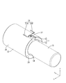
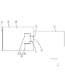
図3及び図4に示すように、バルブボディ11(機器の一例)は、前後方向(軸線方向の一例)に延びる円筒形状をなしている。バルブボディ11の前端部には前壁が設けられており、バルブボディ11の後端部には後壁13が設けられている。バルブボディ11の側壁14と前壁とは直交しており、また、バルブボディ11の側壁14と後壁13とは直交している。
図3及び図4に示すように、バルブボディ11(機器の一例)は、前後方向(軸線方向の一例)に延びる円筒形状をなしている。バルブボディ11の前端部には前壁が設けられており、バルブボディ11の後端部には後壁13が設けられている。バルブボディ11の側壁14と前壁とは直交しており、また、バルブボディ11の側壁14と後壁13とは直交している。
バルブボディ11の内部には図示しないコイルが収容されている。バルブボディ11の後壁13には後方に突出する弁部15が設けられている。弁部15は、バルブボディ11よりも小径な円筒形状をなしている。
コネクタ16
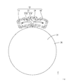
図1に示すように、バルブボディ11の側壁14には、後端部寄りの位置から上方に突出してコネクタ16が設けられている。コネクタ16は、バルブボディ11の周方向に間隔を空けて、バルブボディ11の側壁14から、バルブボディ11の径方向について外方に突出する脚部17を有する。脚部17のうち、バルブボディ11と反対側の端部には、脚部17と一体にフード部18が形成されている。フード部18は前方に開口しており、図示しない相手方コネクタが前方から嵌合可能になっている。脚部17とフード部18とは、絶縁性の合成樹脂を射出成型してなる。バルブボディ11の側壁14と、フード部18との間には、脚部17によって、隙間19が形成されている。
図1に示すように、バルブボディ11の側壁14には、後端部寄りの位置から上方に突出してコネクタ16が設けられている。コネクタ16は、バルブボディ11の周方向に間隔を空けて、バルブボディ11の側壁14から、バルブボディ11の径方向について外方に突出する脚部17を有する。脚部17のうち、バルブボディ11と反対側の端部には、脚部17と一体にフード部18が形成されている。フード部18は前方に開口しており、図示しない相手方コネクタが前方から嵌合可能になっている。脚部17とフード部18とは、絶縁性の合成樹脂を射出成型してなる。バルブボディ11の側壁14と、フード部18との間には、脚部17によって、隙間19が形成されている。
脚部17は、前方から見て、バルブボディ11の外周面に沿った方向についてフード部18の中央位置に設けられている。バルブボディ11の外周面に沿った方向についてフード部18の中央位置とは、完全に中央位置であってもよく、また、中央位置でなくとも実質的に中央位置と認められる程度の領域であってもよい。
フード部18の内部には、複数(本実施形態では2個)の端子21が配されている。端子21のうち、フード部18内に配された部分は、前方に延びるタブ状に形成されている。端子21は導電性の金属製であって、棒状をなしている。端子21を構成する金属は、銅、銅合金等、必要に応じて任意の金属を適宜に選択することができる。端子21の表面には、スズ、ニッケル等の金属からなるメッキ層が形成されていてもよい。
端子21の後端部は、フード部18の後壁33内に埋設されている。詳細には図示しないが、端子21の後端部は、フード部18の後壁33内において、互いに接近する方向に曲がると共に、バルブボディ11の径方向の内方に曲がった状態で脚部17の内部に埋設されて、バルブボディ11内のコイルと電気的に接続されている。
図2に示すように、端子21は、左側に位置する第1端子21Aと、右側に位置する第2端子21Bと、を含む。なお、以下の記述において、第1端子21Aと第2端子21Bとを区別せずに説明する場合には、単に端子21と記載する場合がある。第1端子21Aは、バルブボディ11の側壁14から、バルブボディ11の径方向の外方に突出した後、前方から見て時計回り方向に屈曲した後、前方へ屈曲している。一方、第2端子21Bは、バルブボディ11の側壁14から、バルブボディ11の径方向の外方に突出した後、後方から見て反時計回り方向に屈曲した後、前方へ屈曲している。第1端子21Aと第2端子21Bは、バルブボディ11の側壁14から突出した後、バルブボディ11の周方向に沿って互いに離間する方向に屈曲している。
図1に示すように、フード部18の上壁のうち、前方から見て、第1端子21Aと第2端子21Bとの間の位置には、係止部24が形成されている。この係止部24と、に形成されたロック受け部とが、弾性的に係止することにより、フード部18内に嵌合した相手方コネクタが、抜け止め状態で保持されるようになっている。フード部18内に相手方コネクタが嵌合した状態で、コネクタ16のタブ状をなす端子21と、相手方コネクタの雌端子(図示せず)とが、電気的に接続されるようになっている。
コネクタ16においては、係止部24と、第1端子21Aの前端部と、第2端子21Bの前端部とが、バルブボディ11の周方向に沿って、バルブボディ11の側壁14の外周面に沿って間隔を空けて並んで配されている。
係止部24は、前方から見て、バルブボディ11の外周面に沿った方向についてフード部18の中央位置に設けられている。バルブボディ11の外周面に沿った方向についてフード部18の中央位置とは、完全に中央位置であってもよく、また、中央位置でなくとも実質的に中央位置と認められる程度の領域であってもよい。
磁気シールド部材26
図3に示すように、バルブボディ11の外側には、金属製の磁気シールド部材26が、前方から取り付けられている。磁気シールド部材26を構成する金属としては、銅、銅合金、鉄、鉄合金等、必要に応じて任意の金属を適宜に選択することができる。
図3に示すように、バルブボディ11の外側には、金属製の磁気シールド部材26が、前方から取り付けられている。磁気シールド部材26を構成する金属としては、銅、銅合金、鉄、鉄合金等、必要に応じて任意の金属を適宜に選択することができる。
磁気シールド部材26は、前後方向に延びると共に、前側が塞がれて後側が開口した円筒形状をなしている。磁気シールド部材26の内径寸法は、バルブボディ11の外形寸法と略同じに設定されている。磁気シールド部材26の開口端34には、前方について凹状をなす回避凹部27が設けられている。回避凹部27は、磁気シールド部材26がバルブボディ11に外嵌された状態で、コネクタ16の脚部17に対応する位置に設けられている。回避凹部27の左右方向の幅寸法は、脚部17の左右方向の幅寸法と、同じか、又はやや大きく設定されている。これにより、磁気シールド部材26がバルブボディ11の外嵌された状態で、コネクタ16の脚部17と、磁気シールド部材26とが干渉しないようになっている。フード部18と、バルブボディ11との間の隙間19にも、後述する、磁気シールド部材26の側方シールド部32が配されるようになっている。
磁気シールド部材26の側壁14のうち開口端34寄りの領域は、バルブボディ11の径方向について内方に折れ曲がって、バルブボディ11の後壁13に沿う屈曲部29とされる。屈曲部29の下端縁は、弁部15と干渉しない位置に設定されている。
磁気シールド部材26は、バルブボディ11の外嵌された状態で、バルブボディ11の前壁の前方に位置する前方シールド部31と、バルブボディ11の側壁14をバルブボディ11の径方向の外側から覆う側方シールド部32と、を有する。屈曲部29は、バルブボディ11の後壁13に沿って折れ曲がって側方シールド部32に連なっている。
バルブボディ11の前壁の全ての領域は、前方シールド部31によって覆われている。図4に示すように、バルブボディ11の側壁14は、磁気シールド部材26の回避凹部27に対応する領域を除いて、側方シールド部32によって覆われている。磁気シールド部材26の回避凹部27が設けられた領域においては、バルブボディ11の側壁14が外部に露出している。図3に示すように、バルブボディ11の後壁13の一部は、磁気シールド部材26の屈曲部29によって覆われている。
上記の構成により、バルブボディ11の前方は前方シールド部31によって磁気的にシールドされており、バルブボディ11の側方は回避凹部27に対応する領域を除いて側方シールド部32によって磁気的にシールドされており、バルブボディ11の後方は屈曲部29に対応する領域が磁気的にシールドされている。
実施形態の製造工程
続いて、本実施形態に係るソレノイド10の製造工程の一例について説明する。なお、ソレノイド10の製造工程は以下の記載に限定されない。
続いて、本実施形態に係るソレノイド10の製造工程の一例について説明する。なお、ソレノイド10の製造工程は以下の記載に限定されない。
金属製の棒材をプレス加工することにより、第1端子21A、及び第2端子21Bを所定の形状に形成する。コイルに端子21を接続した後、絶縁性の合成樹脂でインサート成型することにより、バルブボディ11にコネクタ16を一体に形成する。金属板材を所定の形状にプレス加工することにより、磁気シールド部材26を形成する。
磁気シールド部材26を、バルブボディ11の前方から外嵌させる。このとき、磁気シールド部材26の回避凹部27の内部に脚部17が配されるようにする。
次に、磁気シールド部材26の後端縁をバルブボディ11の径方向について内方に折り曲げることにより屈曲部29を形成する。これにより、ソレノイド10が完成する。
その後、相手方コネクタをフード部18内に嵌合させることにより、ソレノイド10と、相手方コネクタとが電気的に接続される。
実施形態の作用効果
続いて、本実施形態の作用効果について説明する。本実施形態は、円筒形状のバルブボディ11の外周面に配されるコネクタ16であって、バルブボディ11の径方向について外方に突出する脚部17と、脚部17の先端部からバルブボディ1の外周面に沿って形成されると共に、相手方コネクタに嵌合可能なフード部18と、脚部17に埋設されると共に、フード部18内においてバルブボディ11の外周面に沿って配された複数の端子21A,21Bと、複数の端子21A,21Bの間に配されると共に、相手方コネクタを係止するための係止部24と、を備える。
続いて、本実施形態の作用効果について説明する。本実施形態は、円筒形状のバルブボディ11の外周面に配されるコネクタ16であって、バルブボディ11の径方向について外方に突出する脚部17と、脚部17の先端部からバルブボディ1の外周面に沿って形成されると共に、相手方コネクタに嵌合可能なフード部18と、脚部17に埋設されると共に、フード部18内においてバルブボディ11の外周面に沿って配された複数の端子21A,21Bと、複数の端子21A,21Bの間に配されると共に、相手方コネクタを係止するための係止部24と、を備える。
上記の構成によれば、係止部24は、第1端子21Aと第2端子21Bとの間に配されているので、係止部24が、第1端子21A及び第2端子21Bの上方に配される場合に比べて、コネクタ16を低背化することができる。
また、本実施形態によれば、脚部17は、バルブボディ11の外周面に沿った方向について、フード部18の中央位置に設けられている。
上記の構成によれば、フード部18に相手方コネクタが嵌合した場合に、フード部18が相手方コネクタから受ける力は、脚部17によって、バルブボディ11の外周面に沿った方向について均等に受けることができる。これにより、相手方コネクタが嵌合した場合に、脚部17を軸にしてフード部18がねじれる方向の力が加わることを抑制することができる。
また、本実施形態によれば、係止部24は、バルブボディ11の外周面に沿った方向について、フード部18の中央位置に設けられている。
上記の構成によれば、複数の端子21A,21Bの間のスペースを有効に利用することができるので、コネクタ16を一層低背化することができる。
また、本実施形態に係るソレノイド10は、軸線方向に沿って延びる円筒形状をなすバルブボディ11と、バルブボディ11の外周面に配されるコネクタ16と、バルブボディ11の外側に取り付けられると共に、一方の端部が開口した筒状をなす金属製の磁気シールド部材26と、を備えたソレノイド10であって、磁気シールド部材26は、一方の端部の開口端34から凹状に形成されて脚部17との干渉を回避する回避凹部27を有する。
上記の構成によれば、バルブボディ11の側壁から突出する脚部17によって、バルブボディ11とフード部18との間に隙間19が設けられており、この隙間19内に、磁気シールド部材26が挿入される。バルブボディ11のうち磁気シールド部材26に覆われない部分は、磁気シールド部材26に回避凹部27が設けられた領域となっている。これにより、バルブボディ11のうち、磁気シールド部材26で覆われない部分を小さくすることができるので、バルブボディ11の磁界効率を向上させることができる。
また、本実施形態によれば、バルブボディ11は、前後方向(軸線方向)について前側に位置する前壁と、後側に位置する後壁13と、を有し、磁気シールド部材26は、バルブボディ11の前壁に沿う前方シールド部31と、バルブボディ11の側壁14に沿う側方シールド部32と、を有し、側方シールド部32の端部は、後壁13に沿って折り曲がって側方シールド部32に連なる屈曲部29とされる。
上記の構成によれば、屈曲部29によってバルブボディ11の後壁13の少なくとも一部が覆われる。これにより、磁気シールド部材26の前方シールド部31、側方シールド部32、及び屈曲部29が磁気的に接続されるので、バルブボディ11の磁界効率を一層向上させることができる。
<他の実施形態>
本明細書に開示された技術は上記記述及び図面によって説明した実施形態に限定されるものではなく、例えば次のような実施形態も本明細書に開示された技術の技術的範囲に含まれる。
本明細書に開示された技術は上記記述及び図面によって説明した実施形態に限定されるものではなく、例えば次のような実施形態も本明細書に開示された技術の技術的範囲に含まれる。
(1)実施形態1においては、コネクタには2個の端子21A,21Bが配される構成としたが、これに限られず、端子は、3個以上でもよい。
(2)実施形態1においては、係止部24は、バルブボディ11の外周面に沿う方向についてフード部18の中央位置に配される構成としたが、これに限られず、係止部24は、フード部18の左端部、又は右端部でもよく、中央位置に限られない。
(3)実施形態1においては、脚部17は、バルブボディ11の外周面に沿う方向についてフード部18の中央位置に配される構成としたが、これに限られず、脚部17は、フード部18の左端部、又は右端部でもよく、中央位置に限られない。
(4)実施形態1においては、バルブボディ11には磁気シールド部材26が外嵌される構成としたが、磁気シールド部材26は省略してもよい。
(5)実施形態1においては、磁気シールド部材26は屈曲部29を有する構成としたが、これに限られず、屈曲部29は省略してもよい。
(6)実施形態1においては、コネクタ16にはタブ状をなす端子21が配され、相手方コネクタには雌端子が配される構成としたが、これに限られず、コネクタに雌端子が配されて、相手方コネクタにタブ状をなす端子が配される構成としてもよい。
10: ソレノイド
11: バルブボディ
13: 後壁
14: 側壁
15: 弁部
16: コネクタ
17: 脚部
18: フード部
19: 隙間
20: 開口部
21: 端子
21A: 第1端子
21B: 第2端子
24: 係止部
26: 磁気シールド部材
27: 回避凹部
29: 屈曲部
31: 前方シールド部
32: 側方シールド部
33: 後壁
34: 開口端
11: バルブボディ
13: 後壁
14: 側壁
15: 弁部
16: コネクタ
17: 脚部
18: フード部
19: 隙間
20: 開口部
21: 端子
21A: 第1端子
21B: 第2端子
24: 係止部
26: 磁気シールド部材
27: 回避凹部
29: 屈曲部
31: 前方シールド部
32: 側方シールド部
33: 後壁
34: 開口端
Claims (5)
- 円筒形状の機器の外周面に配されるコネクタであって、
前記機器の径方向について外方に突出する脚部と、
前記脚部の先端部から前記機器の外周面に沿って形成されると共に、相手方コネクタに嵌合可能なフード部と、
前記脚部に埋設されると共に、前記フード部内において前記機器の外周面に沿って配された複数の端子と、
前記複数の端子の間に配されると共に、前記相手方コネクタを係止するための係止部と、を備えたコネクタ。 - 前記脚部は、前記機器の外周面に沿った方向について、前記フード部の中央位置に設けられている、請求項1に記載のコネクタ。
- 前記係止部は、前記機器の外周面に沿った方向について、前記フード部の中央位置に設けられている、請求項1または請求項2に記載のコネクタ。
- 軸線方向に沿って延びる円筒形状をなす機器と、
前記機器の外周面に配される、請求項1から請求項3のいずれか一項に記載のコネクタと、
前記機器の外側に取り付けられると共に、一方の端部が開口した筒状をなす金属製の磁気シールド部材と、を備えたコネクタ付き機器であって、
前記磁気シールド部材は、前記一方の端部の開口端から凹状に形成されて前記脚部との干渉を回避する回避凹部を有する、コネクタ付き機器。 - 前記機器は、前記軸線方向について前側に位置する前壁と、後側に位置する後壁と、を有し、
前記磁気シールド部材は、前記機器の前記前壁に沿う前方シールド部と、前記機器の側壁に沿う側方シールド部と、を有し、
前記側方シールド部の端部は、前記後壁に沿って折り曲がって前記側方シールド部に連なる屈曲部とされる、請求項4に記載のコネクタ付き機器。
Priority Applications (2)
| Application Number | Priority Date | Filing Date | Title |
|---|---|---|---|
| US17/041,083 US11462862B2 (en) | 2018-03-30 | 2019-03-12 | Connector, and device with connector |
| CN201980021184.0A CN111903008B (zh) | 2018-03-30 | 2019-03-12 | 连接器及带连接器机器 |
Applications Claiming Priority (2)
| Application Number | Priority Date | Filing Date | Title |
|---|---|---|---|
| JP2018-066980 | 2018-03-30 | ||
| JP2018066980A JP7004215B2 (ja) | 2018-03-30 | 2018-03-30 | コネクタ付き機器 |
Publications (1)
| Publication Number | Publication Date |
|---|---|
| WO2019188232A1 true WO2019188232A1 (ja) | 2019-10-03 |
Family
ID=68061606
Family Applications (1)
| Application Number | Title | Priority Date | Filing Date |
|---|---|---|---|
| PCT/JP2019/009868 Ceased WO2019188232A1 (ja) | 2018-03-30 | 2019-03-12 | コネクタ、及びコネクタ付き機器 |
Country Status (4)
| Country | Link |
|---|---|
| US (1) | US11462862B2 (ja) |
| JP (1) | JP7004215B2 (ja) |
| CN (1) | CN111903008B (ja) |
| WO (1) | WO2019188232A1 (ja) |
Citations (3)
| Publication number | Priority date | Publication date | Assignee | Title |
|---|---|---|---|---|
| JPH0541193A (ja) * | 1991-03-20 | 1993-02-19 | Hitachi Ltd | ウエーハ搬送装置を備えた走査電子顕微鏡 |
| JP2015035386A (ja) * | 2013-08-09 | 2015-02-19 | 株式会社オートネットワーク技術研究所 | コネクタ |
| JP2015153661A (ja) * | 2014-02-17 | 2015-08-24 | 株式会社オートネットワーク技術研究所 | コネクタ |
Family Cites Families (5)
| Publication number | Priority date | Publication date | Assignee | Title |
|---|---|---|---|---|
| JP2001266996A (ja) | 2000-03-23 | 2001-09-28 | Yazaki Corp | 連結コネクタ |
| CN202308401U (zh) * | 2011-09-28 | 2012-07-04 | 富士康(昆山)电脑接插件有限公司 | 电连接器及其端子 |
| JP5688063B2 (ja) * | 2012-11-02 | 2015-03-25 | ヒロセ電機株式会社 | 電気コネクタ |
| JP5920376B2 (ja) * | 2014-02-21 | 2016-05-18 | 株式会社デンソー | ソレノイド |
| JP6245526B2 (ja) | 2014-10-17 | 2017-12-13 | 株式会社オートネットワーク技術研究所 | コネクタ |
-
2018
- 2018-03-30 JP JP2018066980A patent/JP7004215B2/ja active Active
-
2019
- 2019-03-12 CN CN201980021184.0A patent/CN111903008B/zh active Active
- 2019-03-12 WO PCT/JP2019/009868 patent/WO2019188232A1/ja not_active Ceased
- 2019-03-12 US US17/041,083 patent/US11462862B2/en active Active
Patent Citations (3)
| Publication number | Priority date | Publication date | Assignee | Title |
|---|---|---|---|---|
| JPH0541193A (ja) * | 1991-03-20 | 1993-02-19 | Hitachi Ltd | ウエーハ搬送装置を備えた走査電子顕微鏡 |
| JP2015035386A (ja) * | 2013-08-09 | 2015-02-19 | 株式会社オートネットワーク技術研究所 | コネクタ |
| JP2015153661A (ja) * | 2014-02-17 | 2015-08-24 | 株式会社オートネットワーク技術研究所 | コネクタ |
Also Published As
| Publication number | Publication date |
|---|---|
| US20210098941A1 (en) | 2021-04-01 |
| US11462862B2 (en) | 2022-10-04 |
| CN111903008B (zh) | 2022-05-24 |
| JP7004215B2 (ja) | 2022-01-21 |
| JP2019179620A (ja) | 2019-10-17 |
| CN111903008A (zh) | 2020-11-06 |
Similar Documents
| Publication | Publication Date | Title |
|---|---|---|
| JP5008492B2 (ja) | シールドコネクタ | |
| JP5333632B2 (ja) | シールドコネクタ | |
| US6461184B2 (en) | Connector | |
| JP6879647B2 (ja) | シールド端子及びシールドコネクタ | |
| JP6847016B2 (ja) | 同軸ケーブル用コネクタ | |
| JP2023028712A (ja) | コネクタ組立体 | |
| JP5459351B2 (ja) | シールドコネクタ | |
| CN114586245A (zh) | 缆线连接器组件 | |
| WO2019181530A1 (ja) | コネクタ付き機器 | |
| WO2019188232A1 (ja) | コネクタ、及びコネクタ付き機器 | |
| US11322895B2 (en) | Connector shielding with a circumferential retention element | |
| JP2021099931A (ja) | シールドコネクタ | |
| JP6813726B2 (ja) | コネクタ | |
| JP4392381B2 (ja) | シールドコネクタ | |
| JP5128359B2 (ja) | シールドコネクタ | |
| JP4830738B2 (ja) | コネクタ | |
| JP5058869B2 (ja) | 同軸コネクタ及び同軸コネクタの組み付け方法 | |
| JP2007141753A (ja) | シールドコネクタ | |
| JP2021015700A (ja) | シールドコネクタ | |
| JP6212775B2 (ja) | コネクタ | |
| JP7590186B2 (ja) | コネクタ | |
| JP7315730B2 (ja) | コンタクトデバイス、特に同軸コンタクトデバイス | |
| JP2019169524A5 (ja) | ||
| JP7004554B2 (ja) | 電気コネクタ | |
| JP2006012498A (ja) | 同軸プラグ |
Legal Events
| Date | Code | Title | Description |
|---|---|---|---|
| 121 | Ep: the epo has been informed by wipo that ep was designated in this application |
Ref document number: 19777511 Country of ref document: EP Kind code of ref document: A1 |
|
| 122 | Ep: pct application non-entry in european phase |
Ref document number: 19777511 Country of ref document: EP Kind code of ref document: A1 |