WO2019181816A1 - Machine de traitement par laser et procédé de traitement par laser - Google Patents
Machine de traitement par laser et procédé de traitement par laser Download PDFInfo
- Publication number
- WO2019181816A1 WO2019181816A1 PCT/JP2019/011029 JP2019011029W WO2019181816A1 WO 2019181816 A1 WO2019181816 A1 WO 2019181816A1 JP 2019011029 W JP2019011029 W JP 2019011029W WO 2019181816 A1 WO2019181816 A1 WO 2019181816A1
- Authority
- WO
- WIPO (PCT)
- Prior art keywords
- laser processing
- laser
- processing
- wavelength band
- light
- Prior art date
Links
Images


Classifications
-
- B—PERFORMING OPERATIONS; TRANSPORTING
- B23—MACHINE TOOLS; METAL-WORKING NOT OTHERWISE PROVIDED FOR
- B23K—SOLDERING OR UNSOLDERING; WELDING; CLADDING OR PLATING BY SOLDERING OR WELDING; CUTTING BY APPLYING HEAT LOCALLY, e.g. FLAME CUTTING; WORKING BY LASER BEAM
- B23K26/00—Working by laser beam, e.g. welding, cutting or boring
- B23K26/20—Bonding
- B23K26/21—Bonding by welding
-
- B—PERFORMING OPERATIONS; TRANSPORTING
- B23—MACHINE TOOLS; METAL-WORKING NOT OTHERWISE PROVIDED FOR
- B23K—SOLDERING OR UNSOLDERING; WELDING; CLADDING OR PLATING BY SOLDERING OR WELDING; CUTTING BY APPLYING HEAT LOCALLY, e.g. FLAME CUTTING; WORKING BY LASER BEAM
- B23K26/00—Working by laser beam, e.g. welding, cutting or boring
- B23K26/02—Positioning or observing the workpiece, e.g. with respect to the point of impact; Aligning, aiming or focusing the laser beam
- B23K26/03—Observing, e.g. monitoring, the workpiece
- B23K26/032—Observing, e.g. monitoring, the workpiece using optical means
-
- B—PERFORMING OPERATIONS; TRANSPORTING
- B23—MACHINE TOOLS; METAL-WORKING NOT OTHERWISE PROVIDED FOR
- B23K—SOLDERING OR UNSOLDERING; WELDING; CLADDING OR PLATING BY SOLDERING OR WELDING; CUTTING BY APPLYING HEAT LOCALLY, e.g. FLAME CUTTING; WORKING BY LASER BEAM
- B23K26/00—Working by laser beam, e.g. welding, cutting or boring
- B23K26/14—Working by laser beam, e.g. welding, cutting or boring using a fluid stream, e.g. a jet of gas, in conjunction with the laser beam; Nozzles therefor
-
- B—PERFORMING OPERATIONS; TRANSPORTING
- B23—MACHINE TOOLS; METAL-WORKING NOT OTHERWISE PROVIDED FOR
- B23K—SOLDERING OR UNSOLDERING; WELDING; CLADDING OR PLATING BY SOLDERING OR WELDING; CUTTING BY APPLYING HEAT LOCALLY, e.g. FLAME CUTTING; WORKING BY LASER BEAM
- B23K26/00—Working by laser beam, e.g. welding, cutting or boring
- B23K26/36—Removing material
- B23K26/38—Removing material by boring or cutting
Definitions
- the present invention relates to a laser processing machine and a laser processing method.
- a laser processing machine includes a laser processing head that irradiates laser light toward a plate-shaped workpiece (metal plate).
- the laser processing head has a focusing lens [focal lens] that focuses laser light toward the workpiece.
- a bend mirror that reflects laser light toward the focusing lens side may be provided on the incident side of the focusing lens inside the laser processing head.
- a laser processing machine includes a monitoring unit [monitoring unit] that monitors a laser processing state using return light from a processing point toward a bend mirror in accordance with laser irradiation (see Patent Document 1 below).
- the return light from the processing point toward the bend mirror is reflected by the bend mirror or transmitted through the bend mirror.
- the light passing through the bend mirror includes scattered light such as light generated on the processing point side including the processing point and the vicinity of the processing point (for example, visible light due to thermal radiation).
- the monitoring unit uses light that passes through the bend mirror.
- a photodiode circuit [photodiode circuit] is provided as a detection unit [detector] for detecting the return light intensity.
- a photodiode circuit is provided as a detection unit for detecting the intensity of the return light transmitted through the bend mirror on the transmission side of the bend mirror (back side of the reflection surface) inside the laser processing head.
- the photodiode circuit receives light and outputs a voltage corresponding to the light intensity.
- the monitoring unit includes a monitoring section that monitors the laser processing state based on the output voltage of the photodiode circuit. For example, the monitoring unit determines whether or not a multiplication value obtained by multiplying the output voltage of the photodiode circuit by a predetermined gain exceeds a threshold value [threshold value] (threshold voltage [threshold voltage]).
- the predetermined gain is a magnification obtained by dividing the reference voltage (for example, 1 V) by the output voltage of the photodiode circuit when performing satisfactory cutting processing.
- the predetermined gain is set by gain adjustment for each processing condition including the material of the workpiece, the thickness of the workpiece, the type of assist gas, and the like.
- the threshold value (threshold voltage) for cutting quality is a threshold value (threshold voltage) for determining the quality of the cutting process, and is one of threshold values (threshold voltage) for determining the laser processing state.
- Patent Documents 2 to 4 are also exemplified as related technologies.
- Japanese Unexamined Patent Publication No. 2011-79037 Japanese Unexamined Patent Publication No. 2012-24778 Japanese Patent Laid-Open No. 2015-148483 Japanese Unexamined Patent Publication No. 2013-86115
- the monitoring unit monitors the laser processing state using a part of the return light intensity (output voltage) in the visible wavelength range and the near infrared wavelength range that can be detected by the photodiode circuit as the detection unit.
- the photodiode circuit when the wavelength at which a photodiode can generate a photocurrent is visible light and some near infrared rays, the photodiode circuit generates a photocurrent from the light generated by laser processing and converts it to a voltage, and the voltage is converted into a light. Output as intensity.
- the normal range of the return light intensity in the wide wavelength band is also various.
- the monitoring unit of the conventional monitoring unit cannot accurately monitor the actual laser processing state under extreme processing conditions. That is, it was difficult to perform stable laser processing under various processing conditions.
- An object of the present invention is to provide a laser processing machine and a laser processing method capable of accurately monitoring an actual laser processing state under various processing conditions.
- a first feature of the present invention is a laser processing machine, which is a laser oscillator that outputs laser light in a 1 ⁇ m wavelength band, and is optically connected to the laser oscillator, while injecting an assist gas toward a workpiece material
- a second feature of the present invention is a laser processing method for performing laser processing on a workpiece material, from a laser processing head optically connected to a laser oscillator that outputs laser light in a 1 ⁇ m wavelength band, to a workpiece material
- a laser beam is emitted while injecting an assist gas toward the laser beam, and along with the irradiation of the laser beam, a return light from the machining point side including the machining point and the vicinity of the machining point to the laser machining head is detected and detected.
- a laser processing method for monitoring a laser processing state by selecting a light level in a specific wavelength band corresponding to a processing condition in a time series from the returned light.
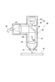
- FIG. 1 is a schematic perspective view of a laser beam machine according to the embodiment.
- FIG. 2 is a schematic cross-sectional view of the processing head of the laser processing machine.
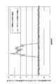
- FIG. 3 is a graph showing the transmittance-wavelength characteristics (transmission characteristics) of the bend mirror.
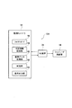
- FIG. 4 is a block diagram of the laser processing machine.
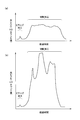
- FIG. 5 is a graph showing the relationship between the ratio of the light level in the 470 nm wavelength band to the light level in the 800 nm wavelength band and the elapsed time when a workpiece material made of iron-based metal is cut.
- FIG. 1 is a schematic perspective view of a laser beam machine according to the embodiment.
- FIG. 2 is a schematic cross-sectional view of the processing head of the laser processing machine.
- FIG. 3 is a graph showing the transmittance-wavelength characteristics (transmission characteristics) of the bend mirror.
- FIG. 4 is a block diagram of the laser processing machine.
- FIG. 5 is a graph showing the relationship between the
- FIG. 6 is a graph showing the relationship between the elapsed time and the ratio of the light level in the 470 nm wavelength band to the light level in the 800 nm wavelength band when a workpiece material made of an aluminum alloy is cut.
- FIG. 7 is a schematic cross-sectional view of a machining head of a laser beam machine according to another embodiment.
- FIG. 8 is a block diagram of the laser beam machine.
- FIG. 9A is a graph showing the test results of the first machining pass / fail judgment when the piercing process and the cutting process are good under the machining condition 1, and FIG. And it is a graph which shows the test result of the 1st process quality determination in case gouging and burning are mixed by the defect of a cutting process.
- FIG. 9A is a graph showing the test results of the first machining pass / fail judgment when the piercing process and the cutting process are good under the machining condition 1
- FIG. And it is a graph which shows the test result of the 1st process quality
- FIG. 10A is a graph showing the test result of the first machining pass / fail judgment when the piercing process is good under the machining condition 2
- FIG. It is a graph which shows the test result of the 1st processing quality determination in case processing is favorable.
- FIG. 11 is a graph showing a test result of the first machining pass / fail judgment when gouging occurs due to a defective cutting process under the machining condition 2.
- FIG. 12 is a graph showing a test result of the first machining pass / fail judgment in the case where burning occurs due to defective cutting under the machining condition 2.
- FIG. 13 is a flowchart of the laser method according to the embodiment.
- the “X-axis direction” is the horizontal direction that is one of the horizontal directions
- the “Y-axis direction” is the front-rear direction that is a horizontal direction perpendicular to the left-right direction
- the “Z-axis direction” is the vertical direction. is there.
- FF indicates the forward direction
- FR indicates the backward direction
- L indicates the left direction
- R indicates the right direction
- U indicates the upward direction
- D indicates the downward direction.
- the laser beam machine 10 irradiates a laser beam (laser beam) of 1 ⁇ m wavelength band [laser) light (laser beam) having a 1 ⁇ m-band wavelength] LB.
- This is a processing machine that performs laser processing (including piercing and cutting) on a material (metal plate) W.
- a specific configuration of the laser processing machine 10 will be described below.
- the laser beam machine 10 includes a machining table 12 that supports the workpiece material W.
- the processing table 12 extends in the X-axis direction.
- the processing table 12 has a plurality of work support plates (skid plates: not shown) extending in the Y-axis direction, and supports the work material W by point contact on the top of each work support plate.
- a plurality of pin holders are formed at intervals in the Y-axis direction.
- a plurality of clamp members [clamper] (not shown) for holding the workpiece W are provided at appropriate positions on the processing table 12.
- the pin holder referred to here is a point support configured by combining a mountain-shaped point support portion and a body portion that prevents the mountain-shaped point support portion from falling down.
- a fiber laser oscillator 14 is disposed as a laser oscillator that outputs (oscillates) laser light LB in the 1 ⁇ m wavelength band.
- the fiber laser oscillator 14 is a laser oscillator having a known configuration as shown in Patent Document 2 above. In the case of a Yb fiber laser, laser light having a wavelength band of approximately 1060 nm to 1100 nm is output.
- a disk laser oscillator, a direct diode laser oscillator (DDL oscillator), or the like may be used as a laser oscillator that outputs laser light LB in the 1 ⁇ m wavelength band.
- DDL oscillator direct diode laser oscillator
- the DDL oscillator can output laser light having a wavelength of 900 nm to 990 nm. That is, the laser beam LB in the 1 ⁇ m wavelength band is a laser beam LB in the wavelength range of 900 nm to 1100 nm.
- a portal-shaped movable frame 16 is provided on the processing table 12 so as to be movable in the X-axis direction.
- the movable frame 16 extends in the Y-axis direction (front-rear direction) so as to straddle the processing table 12.
- the movable frame 16 moves in the X-axis direction by driving an X-axis motor (not shown) provided at an appropriate position on the processing table 12.
- a carriage 18 is provided on the horizontal portion 16a of the movable frame 16 so as to be movable in the Y-axis direction.
- the carriage 18 moves in the Y-axis direction by driving a Y-axis motor (not shown) provided at an appropriate position of the movable frame 16.
- the carriage 18 is provided with a cylindrical laser processing head 20 that can move in the Z-axis direction.
- the carriage 18 includes a Z-axis motor that moves the laser processing head 20 in the Z-axis direction.
- the laser processing head 20 irradiates the laser beam LB while injecting an assist gas toward the workpiece material W from above.
- the laser processing head 20 is provided so as to be movable in the X to Z axis directions above the processing table 12 by driving an X to Z axis motor via a carriage 18 and a movable frame 16.
- the laser processing head 20 is provided with a nozzle 24 at the tip (lower end) of the processing head main body 22 in a detachable manner. Further, the output end of the process fiber 26 that transmits the laser beam LB is connected to the base end portion of the processing head main body 22. The incident end of the process fiber 26 is connected to the emission end of the fiber laser oscillator 14. In other words, the laser processing head 20 is optically connected to the fiber laser oscillator 14 via the process fiber 26. Further, the nozzle 24 side in the processing head main body 22 is connected to an assist gas supply source (not shown) for supplying an assist gas such as oxygen and nitrogen via a pipe (not shown).
- an assist gas supply source not shown
- a collimate lens [collimate lens] 28 for collimating the laser beam LB emitted from the emission end of the process fiber 26 is provided on the proximal end side inside the processing head main body 22.
- a focusing lens [focal lens] 30 that focuses the laser beam LB toward the workpiece is provided on the exit side of the collimating lens 28 inside the processing head body 22.
- the bend mirror 32 that reflects the laser beam LB toward the focusing lens 30 is provided between the collimating lens 28 and the focusing lens 30 inside the processing head main body 22 (on the incident side of the focusing lens 30).
- the transmittance-wavelength characteristic of the bend mirror 32 is shown in FIG.
- the bend mirror 32 substantially totally reflects the laser light LB in the 1 ⁇ m wavelength band used for laser processing, and also substantially reflects the visible light (for example, the red 630 nm wavelength band) used for the guide light of the laser processing machine 10.
- the bend mirror 32 can be designed by changing its transmittance wavelength characteristic according to the wavelength band of an arbitrary laser beam LB used for laser processing.
- the laser beam machine 10 includes an NC (numerical control) device 34 that controls the fiber laser oscillator 14, the X to Z axis motor, the assist gas supply source, and the like based on the machining program.
- the NC device 34 is configured by a computer, and includes a memory that stores a machining program and the like, and a CPU (Central Processing Unit) that interprets and executes the machining program.
- a CPU Central Processing Unit
- the NC device 34 controls the Z-axis motor to move the laser processing head 20 in the Z-axis direction, and controls the lens motor (not shown) to move the focusing lens 30 in the Z-axis direction. By moving, the focal point [focal ⁇ point] of the laser beam LB with respect to the workpiece W is adjusted.
- the NC device 34 controls one or both of the X-axis motor and the Y-axis motor to position the irradiation position of the laser processing head 20 at a predetermined position on the remaining material portion [marginal portion] Wb of the workpiece material W. .
- the NC device 34 controls the fiber laser oscillator 14 and the assist gas supply source, and irradiates the laser beam LB while ejecting the assist gas from the nozzle 24 (the tip of the laser processing head 20) toward the workpiece material W.
- the laser beam machine 10 forms a piercing hole (not shown) at a predetermined position of the remaining material portion Wb of the workpiece W based on the machining program (piercing process).
- the NC device 34 controls the X-axis motor or the Y-axis motor and controls the laser processing head 20 in a state where the laser beam LB is irradiated while jetting the assist gas from the nozzle 24 toward the workpiece material W after the piercing hole is formed. Is moved from the pierced hole to the outline [outline] of the product part [product portion] Wm of the workpiece W. Thereby, the laser beam machine 10 forms a slit from the pierced hole on the remaining material portion Wb to a part of the product portion Wm (approaching process in cutting).
- the NC device 34 moves the laser processing head 20 along the contour of the product portion Wm in a state where the laser beam LB is irradiated while injecting the assist gas after the approach processing. Thereby, the laser beam machine 10 cuts out a product from the workpiece material W (product-cutting process).
- the laser processing machine 10 includes a monitoring unit 36.
- the monitoring unit 36 detects the return light BR ′ transmitted through the bend mirror 32 from the return light BR directed to the bend mirror 32 from the processing point SP side including the vicinity of the processing point SP and the vicinity of the processing point SP. Monitor the laser processing status.
- the cutting point SP side includes a cutting front (an inclined portion that receives the laser beam LB in the processing direction in the cutting groove) and its vicinity. That is, the light detected as the return light BR includes scattered light. In the scattered light, the heat radiation emitted from the material of the workpiece W heated by the laser beam LB and the molecules constituting the gas (assist gas or sublimated metal gas) in the vicinity of the cutting front are generated by the laser beam LB. It contains plasma light that is ionized and moving into cations and electrons.
- the return light BR includes laser light LB reflected by the cutting front, Raman light of the laser light LB, and the like.
- the return light to be detected is the return light BR ′ on the transmission side (the back side of the reflection surface) that has passed through the bend mirror 32 out of the return light BR on the reflection side of the bend mirror 32 inside the processing head body 22.
- a spectroscope 38 that splits the return light BR ′ with a diffraction grating or the like and detects the light intensity of each wavelength band is provided on the transmission side of the bend mirror 32 inside the processing head main body 22.
- the spectroscope 38 is a spectroscope having a known configuration as shown in Patent Document 3 above.
- the spectroscope 38 extracts (selects) light of a plurality of specific wavelength bands according to a processing condition from the return light BR ′ transmitted through the bend mirror 32. Further, the spectroscope 38 detects [in temporal sequence] in time series with the light intensity level of the selected light in the specific wavelength band as the light level (A / D count value [A / D count value]).
- the spectroscope 38 corresponds to a detection unit that detects, in time series, light levels in a plurality of specific wavelength bands in accordance with processing conditions in the return light BR ′ transmitted through the bend mirror 32. Since the spectroscope 38 performs digital processing, the sampling period and data smoothing processing can be changed according to the internal settings.
- the inventors of the present invention have a processing condition that the material of the workpiece material W is an iron-based metal such as mild steel or stainless steel.
- a band (800 ⁇ 20 nm) and a 470 nm wavelength band (470 ⁇ 20 nm) were selected.
- the main component of visible light (red to near infrared) generated by radiant heat on the machining point SP side of the workpiece W It is light in the 800 nm wavelength band.
- the light level in the 800 nm wavelength band changes stably in a time series, so that a normal processing state can be monitored by distinguishing from an abnormal processing state. For this reason, the 800 nm wavelength band was selected (see Example 1 described later).
- the cutting process is good under the processing conditions in which the material of the workpiece W is an iron-based metal, the thickness of the workpiece W is 3 mm or less, and the assist gas is nitrogen (low oxygen concentration or oxygen-free).
- the assist gas is nitrogen (low oxygen concentration or oxygen-free).
- pale visible light is generated on the processing point SP side of the workpiece W.
- the main component of the visible light is light in the 470 nm wavelength band.
- the light level in the 470 nm wavelength band increases when an abnormality occurs due to nitrogen being mixed into the assist gas.
- a normal machining state can be monitored by distinguishing from an abnormal machining state (see Example 2 described later).
- the light level in the 800 nm wavelength band and the light level in the 470 nm wavelength band change stably in time series, but 470 nm.
- the light level in the wavelength band is higher than the light level in the 800 nm wavelength band. Therefore, by comparing the light level in the 800 nm wavelength band and the light level in the 470 nm wavelength band, the normal processing state can be more accurately monitored as distinguished from the abnormal processing state.
- either one of the 800 nm wavelength band and the 470 nm wavelength band may be selected as the specific wavelength band according to the processing conditions, or both may be selected.
- the specific wavelength band according to the processing conditions can be arbitrarily set, and a 510 nm wavelength band other than the 800 nm wavelength band and the 470 nm wavelength band and other wavelength bands may be selected.
- a monitoring controller 40 is provided as a monitoring unit for monitoring the presence or absence of (abnormality of purity). Note that the monitoring controller 40 may be installed in the casing of the NC device 34.
- the monitoring controller 40 has a memory that stores a monitoring program and the like, and a CPU (Central Processing Unit) that interprets and executes the monitoring program. Further, the monitoring controller 40 has a function as a determination information storage unit [judgement information memory] 42, a function as a stored data processing unit [stored data processing section] 44, a function as a judgment unit [judging section] 46, and a signal It has a function as an output section [signal output section] 48.
- a determination information storage unit [judgement information memory] 42
- a function as a stored data processing unit [stored data processing section] 44 a function as a judgment unit [judging section] 46
- a signal It has a function as an output section [signal output section] 48.
- the determination information storage unit 42 stores a threshold value (threshold count value) for determining a laser processing state for each processing condition as determination information.
- the threshold value for determining the laser processing state includes a workpiece material presence threshold value for determining the presence / absence of the workpiece material W on the processing table 12, and piercing processing pass / fail for determining piercing processing quality. Including the threshold value.
- the threshold value for determining the laser processing state includes a threshold value for penetrating a hole for determining the formation of a pierced hole, and a cutting process quality for determining pass / fail during cutting (including approach processing). Includes threshold for Furthermore, the threshold for determining the laser processing state may include a threshold for assist gas abnormality detection for determining whether or not the assist gas is abnormal.
- the determination information storage unit 42 stores a reference transition pattern [reference transition pattern] as determination information for each processing condition.
- the reference transition pattern indicates a temporal transition of the light level in a specific wavelength band that is assumed when the laser processing state is good.
- the reference transition pattern includes a reference transition pattern for piercing processing that is assumed when the piercing processing is good and a reference transition pattern for cutting processing that is assumed when the cutting processing (including approach processing) is good.
- the accumulated data processing unit 44 calculates a moving average value of a light level in a specific wavelength band corresponding to a processing condition as a detection result (detected value) from the spectroscope 38, and accumulates the calculated moving average value in time series. To do. Further, the accumulated data processing unit 44 can also output data obtained by accumulating light levels in a specific wavelength band corresponding to processing conditions in time series to the determination unit 46 as a detection result. The accumulated data processing unit 44 can also output a moving average value of data obtained by accumulating light levels in time series to the determination unit 46 as a detection result.
- the determination unit 46 When the piercing process is started, the determination unit 46 outputs the result of the light level in the specific wavelength band according to the processing conditions output from the accumulated data processing unit 44, and the workpiece material presence threshold stored in the determination information storage unit 42. Are compared to determine whether or not the workpiece W is present. When the result of the light level in the specific wavelength band according to the processing condition is equal to or greater than the threshold value for the presence of the workpiece material, the determination unit 46 determines that the workpiece material W exists on the processing table 12. On the other hand, when the result of the light level is less than the threshold value for presence of the workpiece material, the determination unit 46 determines that the workpiece material W does not exist on the processing table 12.
- the signal output unit 48 continues the predetermined time (for example, several 100 ms) or makes the same determination again after the predetermined time.
- the predetermined time for example, several 100 ms
- the determination unit 46 determines that the workpiece material W exists on the processing table 12, the piercing processing is continued.
- the determination unit 46 compares the result of the light level in the specific wavelength band according to the processing condition output from the accumulated data processing unit 44 with the threshold value for piercing processing quality described in the determination information storage unit 42, Judge the quality of the piercing process.
- the determination unit 46 determines that the piercing processing is normally performed if the result of the light level in the specific wavelength band corresponding to the processing condition is equal to or higher than the threshold for piercing processing, and then the result of the light level is determined. When it changes below the threshold for pierced hole penetration, it is determined that the piercing process has been completed normally.
- the signal output unit 48 interrupts the piercing process even when the piercing process is still being executed, and proceeds to the cutting process (approach process).
- a trigger signal for performing is immediately output to the NC device 34.
- the determination unit 46 determines that the piercing process is not completed or defective.
- the signal output unit 48 confirms that the state continues for a predetermined time (for example, several hundreds of milliseconds) or the same determination is made again after the predetermined time. If an alarm signal is received, an alarm signal is output to the NC device 34.
- the signal output unit 48 may immediately output an alarm signal to the NC device 34.
- the determination unit 46 separately obtains the result of the light level in the specific wavelength band corresponding to the predetermined processing condition output from the accumulated data processing unit 44 and the assist stored in the determination information storage unit 42.
- the presence or absence of an abnormality in the assist gas is determined by comparing with a threshold value for detecting a gas abnormality.
- the specific wavelength band according to predetermined processing conditions is, for example, a 470 nm wavelength band when the material of the workpiece W is an iron-based metal and the assist gas is oxygen.
- the determination unit 46 determines that there is an abnormality in the assist gas due to mixing of different gases.
- the signal output unit 48 When the determination unit 46 determines that there is an abnormality in the assist gas due to mixing of different gases, the signal output unit 48 immediately outputs an alarm signal to the NC device 34.
- the signal output unit 48 may output an alarm signal to the NC device 34 when it is confirmed that the state continues for a predetermined time (for example, several 100 ms) or the same determination is made again after the predetermined time. Good.
- the determination unit 46 compares the result of the light level in the specific wavelength band according to the processing condition output from the accumulated data processing unit 44 with the threshold value for quality of cutting processing stored in the determination information storage unit 42 and performs cutting. Judge the quality of processing. When the result of the light level in the specific wavelength band according to the processing condition exceeds the threshold value for quality of the cutting process, the determination unit 46 determines that the cutting process is defective. On the other hand, when the result of the light level is equal to or less than the threshold value for quality of the cutting process, the determination unit 46 determines that the cutting process is good.
- the signal output unit 48 confirms that the state continues for a predetermined time (for example, several 100 ms) or the same determination is made again after the predetermined time. Sometimes, an alarm signal is output to the NC device 34.
- the determination unit 46 does not determine the quality of the laser processing state based on the result of one light level, but instead of transition data (hereinafter, the light level of the light level) that accumulates the result of the light level from the spectroscope 38 in time series.
- the determination unit 46 may determine whether the laser processing state is good or bad using a temporal transition). This case will be described below, but redundant description will be omitted.
- the determination unit 46 compares the temporal transition of the light level with a reference transition pattern corresponding to the processing condition stored in the determination information storage unit 42 to determine whether the laser processing state is good or bad. That is, the determination unit 46 determines the upper limit value and lower limit value of the light intensity in the normal processing state indicated by the reference transition pattern, the transition cycle of the intensity of the light intensity, and the current processing state indicated by the temporal transition of the light level. The upper limit value and lower limit value of the light intensity and the transition period of the intensity of the light intensity are compared. The determination unit 46 determines whether the laser processing state is good or not based on how far the features are deviated.
- the determination unit 46 stores the reference transition for piercing processing stored in the determination information storage unit 42.
- the quality of the piercing process is judged by comparing the pattern and the temporal transition of the light level in the specific wavelength band according to the processing conditions. Specifically, when the temporal transition of the light level matches the reference transition pattern for piercing processing (these features match), the determination unit 46 determines that the piercing processing has been completed normally. On the other hand, when the temporal transition of the light level is different from the reference transition pattern for piercing processing (the features are different), the determination unit 46 determines that the piercing processing is defective.
- the signal output unit 48 interrupts the piercing process even when the piercing process is still being executed, and proceeds to the cutting process (approach process).
- a trigger signal for performing is immediately output to the NC device 34.
- the signal output unit 48 outputs an alarm signal to the NC device 34.
- the signal output unit 48 may output an alarm signal to the NC device 34 when it is confirmed that the state continues for a predetermined time (for example, several 100 ms) or the same determination is made again after the predetermined time. Good.
- the determination unit 46 compares the temporal transition of the light level in the specific wavelength band corresponding to the processing condition output from the accumulated data processing unit 44 with the reference transition pattern for cutting processing stored in the determination information storage unit 42. Then, the quality of the cutting process is determined. When the temporal transition of the light level matches the reference transition pattern for cutting (their characteristics match), the determination unit 46 determines that the cutting is good. On the other hand, when the temporal transition of the light level is different from the reference transition pattern for cutting process (the characteristics are different), the determination unit 46 determines that the cutting process is defective.
- the signal output unit 48 outputs an alarm signal to the NC device 34 when the determination unit 46 determines that the cutting process is defective.
- the signal output unit 48 may output an alarm signal to the NC device 34 when it is confirmed that the state continues for a predetermined time (for example, several 100 ms) or the same determination is made again after the predetermined time. Good.
- the determination unit 46 may include the material, thickness, and processing type (piercing processing, cutting processing, etc.) of the workpiece material W in the determination criteria for determining the laser processing state.
- the selection and setting of judgment criteria can be arbitrarily changed.
- the spectroscope 38 detects the return light BR ′ transmitted through the bend mirror 32 out of the return light BR from the processing point SP side toward the bend mirror 32, and according to the processing conditions.
- the light intensity of a plurality of specific wavelength bands is detected in time series.
- the determination part 46 is a result (or light level) of the light level of the specific wavelength band according to the threshold value (or reference transition pattern) for determining a laser processing state, and the processing conditions which are the detection results from the spectrometer 38.
- the laser processing state is determined.
- the signal output unit 48 outputs, to the NC device 34, a trigger signal and an alarm signal for shifting to cutting processing (approach processing) based on the determination result of the determination unit 46. Thereby, the laser processing machine 10 can monitor the laser processing state based on the monitoring program.
- the determination unit 46 calculates the ratio of the light level of the 470 nm wavelength band to the light level of the 800 nm wavelength band (hereinafter, appropriately referred to as the ratio of the light level). Thus, it can be determined whether or not gouging has occurred due to the processing failure. Note that gouging in laser processing is a state in which the laser beam LB does not penetrate the workpiece material W, and the molten metal is ejected to the surface of the workpiece material W and does not result in cutting.
- FIG. 5 shows the relationship between the ratio of the light level and the elapsed time when the work material W made of iron-based metal is cut.
- the light level ratio is higher than when the cutting process is not performed satisfactorily. That is, when cutting is performed satisfactorily, the return light BR to the laser processing head 20 has a light level in the 470 nm wavelength band higher than that in the 800 nm wavelength band.
- the return light BR to the laser processing head 20 has a light level in the 470 nm wavelength band higher than that in the 800 nm wavelength band.
- gouging occurs during the cutting process, light in the 800 nm wavelength band increases (or light in the 470 nm wavelength band decreases), so that the light levels in both wavelength bands become equal.
- the determination unit 46 determines whether the light level ratio is “about 1”, the light level ratio is significantly lower than normal, or is constant, or laser processing.
- the light level of the 800 nm wavelength band returning to the head 20 is substantially equal to the light level of the 470 nm wavelength band, it can be determined that a processing defect has occurred.
- FIG. 6 shows the relationship between the ratio of the light level and the elapsed time when the work material W made of an aluminum alloy is cut.
- the ratio of the light level is high both when cutting well and when not cutting well. However, the ratio of the light level is higher when the cutting process is not good than when the cutting process is good. That is, when cutting is performed satisfactorily, the return light BR to the laser processing head 20 has a light level in the 470 nm wavelength band higher than that in the 800 nm wavelength band. However, when it is not cut well (gouging is generated), light in the 470 nm wavelength band increases (or light in the 800 nm wavelength band decreases) compared to when it is cut well. ), The light level ratio is further increased.
- the determination unit 46 determines that the light level ratio is further increased even if the light level ratio is greater than “about 1”, or the light level of the 470 nm wavelength band is 800 nm wavelength band. When the light level is increased, it can be determined that a processing defect has occurred.
- the laser processing machine 10 monitors a laser processing state based on a monitoring program, and among the return light BR ′ to be detected that has passed through the bend mirror 32, a specific wavelength corresponding to the processing condition. Band light is limitedly detected. Therefore, the laser processing machine 10 can monitor the normal processing transition by monitoring the light level of the return light BR ′ to be detected under various processing conditions when the laser processing can be normally performed, and abnormally. It is possible to monitor a normal machining state by distinguishing it from a normal machining state.
- the actual laser processing state is monitored from the transition of the light level under various processing conditions, and stable laser processing can be performed by distinguishing between a normal processing state and an abnormal processing state. it can. Further, when the work material W is made of an iron-based metal and the assist gas is changed, it is possible to monitor the presence or absence of abnormality of the assist gas, and more stable laser processing can be performed.
- the NC device 34 may have a function as the determination information storage unit 42, a function as the accumulated data processing unit 44, a function as the determination unit 46, and a function as the signal output unit 48.
- the spectroscope 38 may detect the light level of the wavelength band used for laser processing in time series in addition to the light level of the specific wavelength band according to the processing conditions.
- a laser beam machine 10A As shown in FIGS. 1 and 7, a laser beam machine 10A according to another embodiment includes a monitoring unit 50 instead of the monitoring unit 36 (see FIG. 2). Other configurations are substantially the same as the configuration of the laser processing machine 10 of the above-described embodiment.
- the monitoring unit 50 of this embodiment will be described.
- symbol is attached
- An optical filter 52 is provided on the transmission side of the bend mirror 32 inside the processing head body 22.
- the optical filter 52 is configured to transmit only light in a plurality of specific wavelength bands corresponding to processing conditions, among the return light BR ′ transmitted through the bend mirror 32.
- a monitoring controller 54 is provided as a monitoring unit that monitors the laser processing state based on a monitoring program.
- the monitoring controller 54 has a photodiode circuit 56 that detects the light intensity of the light transmitted through the optical filter 52.
- the photodiode circuit 56 receives the light transmitted through the optical filter 52 and outputs a voltage corresponding to the light intensity.
- the optical filter 52 and the photodiode circuit 56 detect the light intensity of light in a specific wavelength band corresponding to the processing conditions, among the return light BR that travels from the processing point to the bend mirror 32 with the irradiation of the laser light LB. It corresponds to a detection unit.
- the light intensity may be A / D converted in the photodiode circuit 56 and output as a light level.
- the photodiode circuit 56 may further accumulate data in time series in accordance with the sampling period and output a temporal transition of the accumulated light level.
- the monitoring controller 54 has a memory for storing a monitoring program and the like, and a CPU (Central Processing Unit) that interprets and executes the monitoring program.
- the monitoring controller 54 has a function as a determination information storage unit 58, a function as an accumulated data processing unit 60, a function as a determination unit 62, and a function as a signal output unit 64.
- the determination information storage unit 58, the accumulated data processing unit 60, the determination unit 62, and the signal output unit 64 are respectively added to the above-described determination information storage unit 42, accumulated data processing unit 44, determination unit 46, and signal output unit 48. It corresponds.
- the determination information storage unit 58 stores a threshold value (light level) for determining the laser processing state for each processing condition as determination information. Further, the determination information storage unit 58 stores a reference transition pattern as determination information for each processing condition. The reference transition pattern indicates a temporal transition of the light level in a specific wavelength band that is assumed when the laser processing state is good.
- the accumulated data processing unit 60 accumulates the light level (or temporal transition of the light level) in a specific wavelength band according to the processing conditions as the detection result from the photodiode circuit 56.
- the accumulated data processing unit 60 may perform A / D conversion on the light intensity and accumulate it as a light level. In that case, the accumulated data processing unit 60 may further accumulate data in time series in accordance with the sampling period.
- the determination unit 62 compares the threshold value for determining the laser processing state stored in the determination information storage unit 58 with the result of the light level in the specific wavelength band corresponding to the processing condition output from the accumulated data processing unit 60. Then, the laser processing state is determined. Alternatively, the determination unit 62 compares the reference transition pattern stored in the determination information storage unit 58 with the temporal transition of the light level in the specific wavelength band corresponding to the processing condition output from the accumulated data processing unit 60. The laser processing state is determined. Then, the signal output unit 64 outputs a trigger signal and an alarm signal for shifting to cutting processing (approach processing) to the NC device 34 based on the determination result of the determination unit 62. Thereby, the laser processing machine 10 can monitor a laser processing state based on the monitoring program.
- the bend mirror 32 filters and cuts the laser beam LB and the guide beam. Therefore, if the laser beam LB and the guide light are filtered and cut in front of the spectroscope 38 or the photodiode circuit 56, the bend mirror 32 may not be used.
- the NC device 34 may have a function as the determination information storage unit 58, a function as the accumulated data processing unit 60, a function as the determination unit 62, and a function as the signal output unit 64.
- Example 1 Using the monitoring unit having the same configuration as the monitoring unit 36 (see FIG. 2), the piercing process and the cutting process are good and the cutting process is poor (gouging and burning (burnout)) under the first processing condition.
- the processing test of the first processing pass / fail judgment was performed by examining the light level (A / D count value) of the return light transmitted through the bend mirror.
- the piercing process is good, the cutting process is good, the cutting process is bad (gouging occurs), and the cutting process is bad (burning occurs) under the second processing condition.
- a processing test for determining whether or not the first processing was good was performed.
- the spectroscope of the monitoring unit extracted 20 different wavelengths at wavelength intervals in the 700 nm to 900 nm wavelength band, and detected their light levels in time series. .
- the material of the work material is mild steel, the thickness of the work material is 1 mm, and the assist gas is nitrogen.
- the workpiece material is mild steel, the workpiece thickness is 19 mm, and the assist gas is oxygen.
- the defective state of the cutting process was reproduced in a pseudo manner by defocusing the focused position of the laser beam upward from the surface of the workpiece material.
- Burning is self-burning of a mild steel workpiece having a medium or thick thickness. Self-burning is a state in which iron, which is the main component of mild steel, and oxygen in the assist gas are excessively reacted, and the cutting groove becomes large up to the spray range of the assist gas, so that the cut surface roughness is significantly reduced.
- FIG. 9 (a) and 9 (b) show the results of a machining test for determining the first machining quality under the first machining conditions.
- FIG. 9A and FIG. 9B show only the transition of the light level in the 800 nm wavelength band.
- FIGS. 10A, 10B, 11 and 12 show the results of the machining test for determining the quality of the first machining under the second machining conditions.
- FIGS. 10A, 10B, 11 and 12 show only the transition of the light level in the 800 nm wavelength band.
- the occurrence of gouging can also be monitored by using the ratio of the light level in the 470 nm wavelength band to the light level in the 800 nm wavelength band, as described above with reference to FIG. 5 (FIG. 6). Further, as shown in FIG. 12, when the cutting process is poor (burning occurs), it was confirmed that the light level in the 800 nm wavelength band greatly fluctuated in time series. This is presumably because the cutting front and its surroundings are excessively melted and irregular cut surfaces are formed on the workpiece.
- the same result was able to be obtained also when the material of the workpiece material was other ferrous metals such as stainless steel, and when the thickness of the workpiece material was changed.
- the monitoring program can be used under various processing conditions.
- the laser processing state can be monitored.
- the detection wavelength it was possible to obtain new knowledge that the light level can be stably detected without causing the light level to be excessively high or low.
- Example 2 Using the monitoring unit having the same configuration as the monitoring unit 36 (see FIG. 2), the second processing is performed by examining the light level of the return light transmitted through the bend mirror under the first processing condition when the cutting processing is good. A quality test was conducted. In addition, a processing test for determining whether or not the second processing is good is performed by examining the light level of the return light transmitted through the bend mirror when the assist gas abnormality occurs under the second processing conditions and when the cutting processing is good. It was. In the processing test of the second processing pass / fail judgment, the spectroscope of the monitoring unit extracts 10 different wavelengths with wavelength intervals in the 400 nm to 550 nm wavelength bands and detects their light levels in time series. did.
- the abnormal state of the assist gas is assumed to be a state in which nitrogen remains in the laser processing head after performing the step of switching the assist gas from nitrogen to oxygen. In that state, a piercing simulation was conducted.
- the assist gas is completely detected if the laser processing state is determined by limited detection of light in the 470 nm wavelength band that has passed through the bend mirror. We were able to obtain new knowledge that it was possible to detect that the switch was not made.
- the return light that is a detection target for monitoring the processing state of laser processing is limited to light of a specific wavelength band according to the processing conditions. For this reason, the light level of the return light to be detected does not become excessive (too small) under various processing conditions during normal laser processing. Therefore, by detecting that the light level of the return light stably changes in time series (upper limit value and lower limit value of the light intensity indicating a normal processing state, and a transition period of the intensity of the light intensity), A normal machining state can be monitored by distinguishing from an abnormal machining state.
- the workpiece material W is laser processed while monitoring the processing state as described above.
- the laser beam LB is irradiated from the laser processing head 20 optically connected to the laser oscillator 14 that outputs a laser beam having a wavelength band of 1 ⁇ m toward the workpiece W while ejecting an assist gas (step S1). That is, the workpiece material W is laser processed.
- return light BR ′ (BR) from the processing point side including the processing point and the vicinity of the processing point toward the laser processing head 20 is detected by the detection unit (spectrometer 38 or Detection is performed by the optical filter 52 + photodiode circuit 56) (step S2).
- the detection unit spectrometer 38 or Detection is performed by the optical filter 52 + photodiode circuit 56
- the light level of the specific wavelength band corresponding to the processing conditions is selected in time series (step S3). That is, a time-series transition is obtained for the light level in the specific wavelength band.
- the laser processing state is monitored (step S4). Steps S3 and S4 are performed by the monitoring unit (monitoring controllers 40 and 54), and can be integrated and executed in one process instead of two processes.
- the specific wavelength band according to the processing conditions is, for example, the 800 nm wavelength band, and it is possible to monitor processing defects of ferrous metal (piercing processing defects, cutting processing defects such as gouging and burning) (Example 1).
- the specific wavelength band according to processing conditions is a 470 nm wavelength band, for example, and it can monitor the assist gas defect at the time of iron-type metal processing (Example 2).
- both the 470 nm wavelength band and the 800 nm wavelength band may be simultaneously selected as the specific wavelength band according to the processing conditions. In this case, it is possible to monitor processing defects of iron-based metal and aluminum-based metal (FIGS. 5 and 6).
Landscapes
- Engineering & Computer Science (AREA)
- Physics & Mathematics (AREA)
- Optics & Photonics (AREA)
- Plasma & Fusion (AREA)
- Mechanical Engineering (AREA)
- Laser Beam Processing (AREA)
Abstract
La présente invention concerne une machine de traitement par laser munie : d'un oscillateur laser qui émet de la lumière laser sous une bande de longueur d'onde de 1 µm ; une tête de traitement laser qui est optiquement connectée à l'oscillateur laser et qui irradie la lumière laser tout en injectant un gaz d'assistance vers une pièce à travailler ; une unité de détection qui est disposée à l'intérieur de la tête de traitement laser et qui détecte la lumière renvoyée dirigée vers la tête de traitement laser, de manière concomitante à l'irradiation de la lumière laser, depuis un côté de point de traitement comprenant un point de traitement et une zone à proximité du point de traitement ; et une unité de surveillance qui surveille l'état du traitement laser en sélectionnant, comme série de temps, un niveau de lumière d'une bande de longueur d'onde spécifique correspondant à une condition de traitement, parmi la lumière renvoyée détectée par l'unité de détection. L'état du traitement laser est surveillé sur la base du niveau de lumière en série de temps de la bande de longueur d'onde spécifique.
Priority Applications (1)
| Application Number | Priority Date | Filing Date | Title |
|---|---|---|---|
| EP19770370.5A EP3769897B1 (fr) | 2018-03-23 | 2019-03-18 | Machine de traitement par laser et procédé de traitement par laser |
Applications Claiming Priority (2)
| Application Number | Priority Date | Filing Date | Title |
|---|---|---|---|
| JP2018-055668 | 2018-03-23 | ||
| JP2018055668A JP6725572B2 (ja) | 2018-03-23 | 2018-03-23 | レーザ加工機及びレーザ加工方法 |
Publications (1)
| Publication Number | Publication Date |
|---|---|
| WO2019181816A1 true WO2019181816A1 (fr) | 2019-09-26 |
Family
ID=67986267
Family Applications (1)
| Application Number | Title | Priority Date | Filing Date |
|---|---|---|---|
| PCT/JP2019/011029 WO2019181816A1 (fr) | 2018-03-23 | 2019-03-18 | Machine de traitement par laser et procédé de traitement par laser |
Country Status (3)
| Country | Link |
|---|---|
| EP (1) | EP3769897B1 (fr) |
| JP (1) | JP6725572B2 (fr) |
| WO (1) | WO2019181816A1 (fr) |
Families Citing this family (2)
| Publication number | Priority date | Publication date | Assignee | Title |
|---|---|---|---|---|
| US20230321750A1 (en) | 2020-08-27 | 2023-10-12 | Mitsubishi Electric Corporation | Laser machining apparatus |
| KR102592154B1 (ko) * | 2021-08-13 | 2023-10-23 | 한국원자력연구원 | 분광기를 이용한 레이저절단 모니터링 방법 및 장치 |
Citations (9)
| Publication number | Priority date | Publication date | Assignee | Title |
|---|---|---|---|---|
| JP2002210575A (ja) * | 2001-01-18 | 2002-07-30 | Nippon Steel Corp | レーザ溶接における溶接状態判定方法 |
| JP2003053568A (ja) * | 2001-08-09 | 2003-02-26 | Nippei Toyama Corp | レーザ切断加工制御方法及び装置 |
| JP2006521933A (ja) * | 2003-03-31 | 2006-09-28 | ハイパーサーム インコーポレイテッド | レーザ材料加工システムのための集中制御アーキテクチャ |
| JP2011079037A (ja) | 2009-10-09 | 2011-04-21 | Amada Co Ltd | レーザ加工装置及び同装置を用いたレーザ加工状態監視方法 |
| JP2012024778A (ja) | 2010-07-20 | 2012-02-09 | Amada Co Ltd | ファイバレーザ発振器及びファイバレーザ加工機 |
| JP2013086115A (ja) | 2011-10-17 | 2013-05-13 | Amada Co Ltd | 加工モニタリング装置及びその方法 |
| JP2015148483A (ja) | 2014-02-05 | 2015-08-20 | 浜松ホトニクス株式会社 | 分光器 |
| JP2017024046A (ja) * | 2015-07-23 | 2017-02-02 | 有限会社西原電子 | レーザ溶接監視装置とレーザ溶接監視方法 |
| JP2018055668A (ja) | 2016-09-26 | 2018-04-05 | 富士ゼロックス株式会社 | 画像処理装置及びプログラム |
Family Cites Families (6)
| Publication number | Priority date | Publication date | Assignee | Title |
|---|---|---|---|---|
| JP3511311B2 (ja) * | 1994-06-24 | 2004-03-29 | 三菱電機株式会社 | ピアス加工完了判定方法,それを用いたレーザ加工機およびそのレーザ加工方法 |
| IT1401726B1 (it) * | 2010-08-31 | 2013-08-02 | Consiglio Nazionale Ricerche | Metodo per l'individuazione di difettosita' nel processo di saldatura laser continua di parti metalliche. |
| JP6535480B2 (ja) * | 2015-02-24 | 2019-06-26 | 株式会社アマダホールディングス | レーザ加工状態判別方法及び装置 |
| JP6134805B2 (ja) * | 2015-03-10 | 2017-05-24 | 技術研究組合次世代3D積層造形技術総合開発機構 | 光加工ヘッドおよび3次元造形装置 |
| US9959613B2 (en) * | 2015-03-20 | 2018-05-01 | Technology Research Association For Future Additive Manufacturing | Optical Processing head, optical processing apparatus, and control method and control program of optical processing apparatus |
| DE102016208264A1 (de) * | 2016-05-13 | 2017-11-16 | Trumpf Werkzeugmaschinen Gmbh + Co. Kg | Verfahren und Vorrichtung zur Überwachung, insbesondere zur Regelung, eines Schneidprozesses |
-
2018
- 2018-03-23 JP JP2018055668A patent/JP6725572B2/ja active Active
-
2019
- 2019-03-18 WO PCT/JP2019/011029 patent/WO2019181816A1/fr active Application Filing
- 2019-03-18 EP EP19770370.5A patent/EP3769897B1/fr active Active
Patent Citations (9)
| Publication number | Priority date | Publication date | Assignee | Title |
|---|---|---|---|---|
| JP2002210575A (ja) * | 2001-01-18 | 2002-07-30 | Nippon Steel Corp | レーザ溶接における溶接状態判定方法 |
| JP2003053568A (ja) * | 2001-08-09 | 2003-02-26 | Nippei Toyama Corp | レーザ切断加工制御方法及び装置 |
| JP2006521933A (ja) * | 2003-03-31 | 2006-09-28 | ハイパーサーム インコーポレイテッド | レーザ材料加工システムのための集中制御アーキテクチャ |
| JP2011079037A (ja) | 2009-10-09 | 2011-04-21 | Amada Co Ltd | レーザ加工装置及び同装置を用いたレーザ加工状態監視方法 |
| JP2012024778A (ja) | 2010-07-20 | 2012-02-09 | Amada Co Ltd | ファイバレーザ発振器及びファイバレーザ加工機 |
| JP2013086115A (ja) | 2011-10-17 | 2013-05-13 | Amada Co Ltd | 加工モニタリング装置及びその方法 |
| JP2015148483A (ja) | 2014-02-05 | 2015-08-20 | 浜松ホトニクス株式会社 | 分光器 |
| JP2017024046A (ja) * | 2015-07-23 | 2017-02-02 | 有限会社西原電子 | レーザ溶接監視装置とレーザ溶接監視方法 |
| JP2018055668A (ja) | 2016-09-26 | 2018-04-05 | 富士ゼロックス株式会社 | 画像処理装置及びプログラム |
Non-Patent Citations (1)
| Title |
|---|
| See also references of EP3769897A4 |
Also Published As
| Publication number | Publication date |
|---|---|
| JP6725572B2 (ja) | 2020-07-22 |
| EP3769897B1 (fr) | 2022-07-27 |
| EP3769897A4 (fr) | 2021-05-26 |
| JP2019166543A (ja) | 2019-10-03 |
| EP3769897A1 (fr) | 2021-01-27 |
Similar Documents
| Publication | Publication Date | Title |
|---|---|---|
| US10888954B2 (en) | Method for monitoring and controlling a laser cutting process | |
| US20130068738A1 (en) | Laser cutting head and method for cutting a workpiece by means of a laser cutting head | |
| KR101515736B1 (ko) | 공작물에 대한 절삭 가공을 모니터링하는 절삭 가공의 모니터링 방법 | |
| US11491583B2 (en) | Methods and apparatuses for controlling cutting processes | |
| US11420292B2 (en) | Cutting a workpiece | |
| US20140021177A1 (en) | Method and Apparatus for Machining a Workpiece by Means of a Laser Beam | |
| CN113365774B (zh) | 用于自动化地求取激光加工参数对激光加工的影响的方法以及激光加工机和计算机程序产品 | |
| WO2019181816A1 (fr) | Machine de traitement par laser et procédé de traitement par laser | |
| US20170246708A1 (en) | Laser processing device capable of starting laser processing while reducing reflected laser beam | |
| JP7379542B2 (ja) | レーザによる自動材料認識 | |
| JP2005131645A (ja) | レーザ加工方法及び加工状態判断方法 | |
| JP2016155140A (ja) | レーザ加工判別方法及び装置 | |
| Wiesemann | 2.8 Process monitoring and closed-loop control: 2 Production engineering | |
| JP4719173B2 (ja) | レーザ溶接方法 | |
| US10928615B2 (en) | Laser processing device having approach function of processing head | |
| JP3287133B2 (ja) | レーザ加工機 | |
| JP2018202421A (ja) | レーザ加工ヘッド及びレーザ加工機 | |
| JPH07214357A (ja) | レーザ加工機 | |
| JP2021186816A (ja) | レーザ加工装置 | |
| JP2001071164A (ja) | 被加工部のモニタリング方法及びその装置 | |
| JPH08215869A (ja) | レーザ溶接方法およびその装置 | |
| JPH0691384A (ja) | レーザ加工機 | |
| JP6824092B2 (ja) | レーザ加工方法及びレーザ加工装置 | |
| JPH06246466A (ja) | レーザ加工方法 | |
| JP2017217675A (ja) | レーザクラッド加工装置 |
Legal Events
| Date | Code | Title | Description |
|---|---|---|---|
| 121 | Ep: the epo has been informed by wipo that ep was designated in this application |
Ref document number: 19770370 Country of ref document: EP Kind code of ref document: A1 |
|
| NENP | Non-entry into the national phase |
Ref country code: DE |
|
| WWE | Wipo information: entry into national phase |
Ref document number: 2019770370 Country of ref document: EP |