WO2019181816A1 - Laser processing machine and laser processing method - Google Patents
Laser processing machine and laser processing method Download PDFInfo
- Publication number
- WO2019181816A1 WO2019181816A1 PCT/JP2019/011029 JP2019011029W WO2019181816A1 WO 2019181816 A1 WO2019181816 A1 WO 2019181816A1 JP 2019011029 W JP2019011029 W JP 2019011029W WO 2019181816 A1 WO2019181816 A1 WO 2019181816A1
- Authority
- WO
- WIPO (PCT)
- Prior art keywords
- laser processing
- laser
- processing
- wavelength band
- light
- Prior art date
Links
Images


Classifications
-
- B—PERFORMING OPERATIONS; TRANSPORTING
- B23—MACHINE TOOLS; METAL-WORKING NOT OTHERWISE PROVIDED FOR
- B23K—SOLDERING OR UNSOLDERING; WELDING; CLADDING OR PLATING BY SOLDERING OR WELDING; CUTTING BY APPLYING HEAT LOCALLY, e.g. FLAME CUTTING; WORKING BY LASER BEAM
- B23K26/00—Working by laser beam, e.g. welding, cutting or boring
- B23K26/20—Bonding
- B23K26/21—Bonding by welding
-
- B—PERFORMING OPERATIONS; TRANSPORTING
- B23—MACHINE TOOLS; METAL-WORKING NOT OTHERWISE PROVIDED FOR
- B23K—SOLDERING OR UNSOLDERING; WELDING; CLADDING OR PLATING BY SOLDERING OR WELDING; CUTTING BY APPLYING HEAT LOCALLY, e.g. FLAME CUTTING; WORKING BY LASER BEAM
- B23K26/00—Working by laser beam, e.g. welding, cutting or boring
- B23K26/02—Positioning or observing the workpiece, e.g. with respect to the point of impact; Aligning, aiming or focusing the laser beam
- B23K26/03—Observing, e.g. monitoring, the workpiece
- B23K26/032—Observing, e.g. monitoring, the workpiece using optical means
-
- B—PERFORMING OPERATIONS; TRANSPORTING
- B23—MACHINE TOOLS; METAL-WORKING NOT OTHERWISE PROVIDED FOR
- B23K—SOLDERING OR UNSOLDERING; WELDING; CLADDING OR PLATING BY SOLDERING OR WELDING; CUTTING BY APPLYING HEAT LOCALLY, e.g. FLAME CUTTING; WORKING BY LASER BEAM
- B23K26/00—Working by laser beam, e.g. welding, cutting or boring
- B23K26/14—Working by laser beam, e.g. welding, cutting or boring using a fluid stream, e.g. a jet of gas, in conjunction with the laser beam; Nozzles therefor
-
- B—PERFORMING OPERATIONS; TRANSPORTING
- B23—MACHINE TOOLS; METAL-WORKING NOT OTHERWISE PROVIDED FOR
- B23K—SOLDERING OR UNSOLDERING; WELDING; CLADDING OR PLATING BY SOLDERING OR WELDING; CUTTING BY APPLYING HEAT LOCALLY, e.g. FLAME CUTTING; WORKING BY LASER BEAM
- B23K26/00—Working by laser beam, e.g. welding, cutting or boring
- B23K26/36—Removing material
- B23K26/38—Removing material by boring or cutting
Definitions
- the present invention relates to a laser processing machine and a laser processing method.
- a laser processing machine includes a laser processing head that irradiates laser light toward a plate-shaped workpiece (metal plate).
- the laser processing head has a focusing lens [focal lens] that focuses laser light toward the workpiece.
- a bend mirror that reflects laser light toward the focusing lens side may be provided on the incident side of the focusing lens inside the laser processing head.
- a laser processing machine includes a monitoring unit [monitoring unit] that monitors a laser processing state using return light from a processing point toward a bend mirror in accordance with laser irradiation (see Patent Document 1 below).
- the return light from the processing point toward the bend mirror is reflected by the bend mirror or transmitted through the bend mirror.
- the light passing through the bend mirror includes scattered light such as light generated on the processing point side including the processing point and the vicinity of the processing point (for example, visible light due to thermal radiation).
- the monitoring unit uses light that passes through the bend mirror.
- a photodiode circuit [photodiode circuit] is provided as a detection unit [detector] for detecting the return light intensity.
- a photodiode circuit is provided as a detection unit for detecting the intensity of the return light transmitted through the bend mirror on the transmission side of the bend mirror (back side of the reflection surface) inside the laser processing head.
- the photodiode circuit receives light and outputs a voltage corresponding to the light intensity.
- the monitoring unit includes a monitoring section that monitors the laser processing state based on the output voltage of the photodiode circuit. For example, the monitoring unit determines whether or not a multiplication value obtained by multiplying the output voltage of the photodiode circuit by a predetermined gain exceeds a threshold value [threshold value] (threshold voltage [threshold voltage]).
- the predetermined gain is a magnification obtained by dividing the reference voltage (for example, 1 V) by the output voltage of the photodiode circuit when performing satisfactory cutting processing.
- the predetermined gain is set by gain adjustment for each processing condition including the material of the workpiece, the thickness of the workpiece, the type of assist gas, and the like.
- the threshold value (threshold voltage) for cutting quality is a threshold value (threshold voltage) for determining the quality of the cutting process, and is one of threshold values (threshold voltage) for determining the laser processing state.
- Patent Documents 2 to 4 are also exemplified as related technologies.
- Japanese Unexamined Patent Publication No. 2011-79037 Japanese Unexamined Patent Publication No. 2012-24778 Japanese Patent Laid-Open No. 2015-148483 Japanese Unexamined Patent Publication No. 2013-86115
- the monitoring unit monitors the laser processing state using a part of the return light intensity (output voltage) in the visible wavelength range and the near infrared wavelength range that can be detected by the photodiode circuit as the detection unit.
- the photodiode circuit when the wavelength at which a photodiode can generate a photocurrent is visible light and some near infrared rays, the photodiode circuit generates a photocurrent from the light generated by laser processing and converts it to a voltage, and the voltage is converted into a light. Output as intensity.
- the normal range of the return light intensity in the wide wavelength band is also various.
- the monitoring unit of the conventional monitoring unit cannot accurately monitor the actual laser processing state under extreme processing conditions. That is, it was difficult to perform stable laser processing under various processing conditions.
- An object of the present invention is to provide a laser processing machine and a laser processing method capable of accurately monitoring an actual laser processing state under various processing conditions.
- a first feature of the present invention is a laser processing machine, which is a laser oscillator that outputs laser light in a 1 ⁇ m wavelength band, and is optically connected to the laser oscillator, while injecting an assist gas toward a workpiece material
- a second feature of the present invention is a laser processing method for performing laser processing on a workpiece material, from a laser processing head optically connected to a laser oscillator that outputs laser light in a 1 ⁇ m wavelength band, to a workpiece material
- a laser beam is emitted while injecting an assist gas toward the laser beam, and along with the irradiation of the laser beam, a return light from the machining point side including the machining point and the vicinity of the machining point to the laser machining head is detected and detected.
- a laser processing method for monitoring a laser processing state by selecting a light level in a specific wavelength band corresponding to a processing condition in a time series from the returned light.
- FIG. 1 is a schematic perspective view of a laser beam machine according to the embodiment.
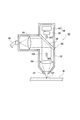
- FIG. 2 is a schematic cross-sectional view of the processing head of the laser processing machine.
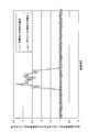
- FIG. 3 is a graph showing the transmittance-wavelength characteristics (transmission characteristics) of the bend mirror.
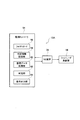
- FIG. 4 is a block diagram of the laser processing machine.
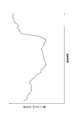
- FIG. 5 is a graph showing the relationship between the ratio of the light level in the 470 nm wavelength band to the light level in the 800 nm wavelength band and the elapsed time when a workpiece material made of iron-based metal is cut.
- FIG. 1 is a schematic perspective view of a laser beam machine according to the embodiment.
- FIG. 2 is a schematic cross-sectional view of the processing head of the laser processing machine.
- FIG. 3 is a graph showing the transmittance-wavelength characteristics (transmission characteristics) of the bend mirror.
- FIG. 4 is a block diagram of the laser processing machine.
- FIG. 5 is a graph showing the relationship between the
- FIG. 6 is a graph showing the relationship between the elapsed time and the ratio of the light level in the 470 nm wavelength band to the light level in the 800 nm wavelength band when a workpiece material made of an aluminum alloy is cut.
- FIG. 7 is a schematic cross-sectional view of a machining head of a laser beam machine according to another embodiment.
- FIG. 8 is a block diagram of the laser beam machine.
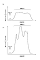
- FIG. 9A is a graph showing the test results of the first machining pass / fail judgment when the piercing process and the cutting process are good under the machining condition 1, and FIG. And it is a graph which shows the test result of the 1st process quality determination in case gouging and burning are mixed by the defect of a cutting process.
- FIG. 9A is a graph showing the test results of the first machining pass / fail judgment when the piercing process and the cutting process are good under the machining condition 1
- FIG. And it is a graph which shows the test result of the 1st process quality
- FIG. 10A is a graph showing the test result of the first machining pass / fail judgment when the piercing process is good under the machining condition 2
- FIG. It is a graph which shows the test result of the 1st processing quality determination in case processing is favorable.
- FIG. 11 is a graph showing a test result of the first machining pass / fail judgment when gouging occurs due to a defective cutting process under the machining condition 2.
- FIG. 12 is a graph showing a test result of the first machining pass / fail judgment in the case where burning occurs due to defective cutting under the machining condition 2.
- FIG. 13 is a flowchart of the laser method according to the embodiment.
- the “X-axis direction” is the horizontal direction that is one of the horizontal directions
- the “Y-axis direction” is the front-rear direction that is a horizontal direction perpendicular to the left-right direction
- the “Z-axis direction” is the vertical direction. is there.
- FF indicates the forward direction
- FR indicates the backward direction
- L indicates the left direction
- R indicates the right direction
- U indicates the upward direction
- D indicates the downward direction.
- the laser beam machine 10 irradiates a laser beam (laser beam) of 1 ⁇ m wavelength band [laser) light (laser beam) having a 1 ⁇ m-band wavelength] LB.
- This is a processing machine that performs laser processing (including piercing and cutting) on a material (metal plate) W.
- a specific configuration of the laser processing machine 10 will be described below.
- the laser beam machine 10 includes a machining table 12 that supports the workpiece material W.
- the processing table 12 extends in the X-axis direction.
- the processing table 12 has a plurality of work support plates (skid plates: not shown) extending in the Y-axis direction, and supports the work material W by point contact on the top of each work support plate.
- a plurality of pin holders are formed at intervals in the Y-axis direction.
- a plurality of clamp members [clamper] (not shown) for holding the workpiece W are provided at appropriate positions on the processing table 12.
- the pin holder referred to here is a point support configured by combining a mountain-shaped point support portion and a body portion that prevents the mountain-shaped point support portion from falling down.
- a fiber laser oscillator 14 is disposed as a laser oscillator that outputs (oscillates) laser light LB in the 1 ⁇ m wavelength band.
- the fiber laser oscillator 14 is a laser oscillator having a known configuration as shown in Patent Document 2 above. In the case of a Yb fiber laser, laser light having a wavelength band of approximately 1060 nm to 1100 nm is output.
- a disk laser oscillator, a direct diode laser oscillator (DDL oscillator), or the like may be used as a laser oscillator that outputs laser light LB in the 1 ⁇ m wavelength band.
- DDL oscillator direct diode laser oscillator
- the DDL oscillator can output laser light having a wavelength of 900 nm to 990 nm. That is, the laser beam LB in the 1 ⁇ m wavelength band is a laser beam LB in the wavelength range of 900 nm to 1100 nm.
- a portal-shaped movable frame 16 is provided on the processing table 12 so as to be movable in the X-axis direction.
- the movable frame 16 extends in the Y-axis direction (front-rear direction) so as to straddle the processing table 12.
- the movable frame 16 moves in the X-axis direction by driving an X-axis motor (not shown) provided at an appropriate position on the processing table 12.
- a carriage 18 is provided on the horizontal portion 16a of the movable frame 16 so as to be movable in the Y-axis direction.
- the carriage 18 moves in the Y-axis direction by driving a Y-axis motor (not shown) provided at an appropriate position of the movable frame 16.
- the carriage 18 is provided with a cylindrical laser processing head 20 that can move in the Z-axis direction.
- the carriage 18 includes a Z-axis motor that moves the laser processing head 20 in the Z-axis direction.
- the laser processing head 20 irradiates the laser beam LB while injecting an assist gas toward the workpiece material W from above.
- the laser processing head 20 is provided so as to be movable in the X to Z axis directions above the processing table 12 by driving an X to Z axis motor via a carriage 18 and a movable frame 16.
- the laser processing head 20 is provided with a nozzle 24 at the tip (lower end) of the processing head main body 22 in a detachable manner. Further, the output end of the process fiber 26 that transmits the laser beam LB is connected to the base end portion of the processing head main body 22. The incident end of the process fiber 26 is connected to the emission end of the fiber laser oscillator 14. In other words, the laser processing head 20 is optically connected to the fiber laser oscillator 14 via the process fiber 26. Further, the nozzle 24 side in the processing head main body 22 is connected to an assist gas supply source (not shown) for supplying an assist gas such as oxygen and nitrogen via a pipe (not shown).
- an assist gas supply source not shown
- a collimate lens [collimate lens] 28 for collimating the laser beam LB emitted from the emission end of the process fiber 26 is provided on the proximal end side inside the processing head main body 22.
- a focusing lens [focal lens] 30 that focuses the laser beam LB toward the workpiece is provided on the exit side of the collimating lens 28 inside the processing head body 22.
- the bend mirror 32 that reflects the laser beam LB toward the focusing lens 30 is provided between the collimating lens 28 and the focusing lens 30 inside the processing head main body 22 (on the incident side of the focusing lens 30).
- the transmittance-wavelength characteristic of the bend mirror 32 is shown in FIG.
- the bend mirror 32 substantially totally reflects the laser light LB in the 1 ⁇ m wavelength band used for laser processing, and also substantially reflects the visible light (for example, the red 630 nm wavelength band) used for the guide light of the laser processing machine 10.
- the bend mirror 32 can be designed by changing its transmittance wavelength characteristic according to the wavelength band of an arbitrary laser beam LB used for laser processing.
- the laser beam machine 10 includes an NC (numerical control) device 34 that controls the fiber laser oscillator 14, the X to Z axis motor, the assist gas supply source, and the like based on the machining program.
- the NC device 34 is configured by a computer, and includes a memory that stores a machining program and the like, and a CPU (Central Processing Unit) that interprets and executes the machining program.
- a CPU Central Processing Unit
- the NC device 34 controls the Z-axis motor to move the laser processing head 20 in the Z-axis direction, and controls the lens motor (not shown) to move the focusing lens 30 in the Z-axis direction. By moving, the focal point [focal ⁇ point] of the laser beam LB with respect to the workpiece W is adjusted.
- the NC device 34 controls one or both of the X-axis motor and the Y-axis motor to position the irradiation position of the laser processing head 20 at a predetermined position on the remaining material portion [marginal portion] Wb of the workpiece material W. .
- the NC device 34 controls the fiber laser oscillator 14 and the assist gas supply source, and irradiates the laser beam LB while ejecting the assist gas from the nozzle 24 (the tip of the laser processing head 20) toward the workpiece material W.
- the laser beam machine 10 forms a piercing hole (not shown) at a predetermined position of the remaining material portion Wb of the workpiece W based on the machining program (piercing process).
- the NC device 34 controls the X-axis motor or the Y-axis motor and controls the laser processing head 20 in a state where the laser beam LB is irradiated while jetting the assist gas from the nozzle 24 toward the workpiece material W after the piercing hole is formed. Is moved from the pierced hole to the outline [outline] of the product part [product portion] Wm of the workpiece W. Thereby, the laser beam machine 10 forms a slit from the pierced hole on the remaining material portion Wb to a part of the product portion Wm (approaching process in cutting).
- the NC device 34 moves the laser processing head 20 along the contour of the product portion Wm in a state where the laser beam LB is irradiated while injecting the assist gas after the approach processing. Thereby, the laser beam machine 10 cuts out a product from the workpiece material W (product-cutting process).
- the laser processing machine 10 includes a monitoring unit 36.
- the monitoring unit 36 detects the return light BR ′ transmitted through the bend mirror 32 from the return light BR directed to the bend mirror 32 from the processing point SP side including the vicinity of the processing point SP and the vicinity of the processing point SP. Monitor the laser processing status.
- the cutting point SP side includes a cutting front (an inclined portion that receives the laser beam LB in the processing direction in the cutting groove) and its vicinity. That is, the light detected as the return light BR includes scattered light. In the scattered light, the heat radiation emitted from the material of the workpiece W heated by the laser beam LB and the molecules constituting the gas (assist gas or sublimated metal gas) in the vicinity of the cutting front are generated by the laser beam LB. It contains plasma light that is ionized and moving into cations and electrons.
- the return light BR includes laser light LB reflected by the cutting front, Raman light of the laser light LB, and the like.
- the return light to be detected is the return light BR ′ on the transmission side (the back side of the reflection surface) that has passed through the bend mirror 32 out of the return light BR on the reflection side of the bend mirror 32 inside the processing head body 22.
- a spectroscope 38 that splits the return light BR ′ with a diffraction grating or the like and detects the light intensity of each wavelength band is provided on the transmission side of the bend mirror 32 inside the processing head main body 22.
- the spectroscope 38 is a spectroscope having a known configuration as shown in Patent Document 3 above.
- the spectroscope 38 extracts (selects) light of a plurality of specific wavelength bands according to a processing condition from the return light BR ′ transmitted through the bend mirror 32. Further, the spectroscope 38 detects [in temporal sequence] in time series with the light intensity level of the selected light in the specific wavelength band as the light level (A / D count value [A / D count value]).
- the spectroscope 38 corresponds to a detection unit that detects, in time series, light levels in a plurality of specific wavelength bands in accordance with processing conditions in the return light BR ′ transmitted through the bend mirror 32. Since the spectroscope 38 performs digital processing, the sampling period and data smoothing processing can be changed according to the internal settings.
- the inventors of the present invention have a processing condition that the material of the workpiece material W is an iron-based metal such as mild steel or stainless steel.
- a band (800 ⁇ 20 nm) and a 470 nm wavelength band (470 ⁇ 20 nm) were selected.
- the main component of visible light (red to near infrared) generated by radiant heat on the machining point SP side of the workpiece W It is light in the 800 nm wavelength band.
- the light level in the 800 nm wavelength band changes stably in a time series, so that a normal processing state can be monitored by distinguishing from an abnormal processing state. For this reason, the 800 nm wavelength band was selected (see Example 1 described later).
- the cutting process is good under the processing conditions in which the material of the workpiece W is an iron-based metal, the thickness of the workpiece W is 3 mm or less, and the assist gas is nitrogen (low oxygen concentration or oxygen-free).
- the assist gas is nitrogen (low oxygen concentration or oxygen-free).
- pale visible light is generated on the processing point SP side of the workpiece W.
- the main component of the visible light is light in the 470 nm wavelength band.
- the light level in the 470 nm wavelength band increases when an abnormality occurs due to nitrogen being mixed into the assist gas.
- a normal machining state can be monitored by distinguishing from an abnormal machining state (see Example 2 described later).
- the light level in the 800 nm wavelength band and the light level in the 470 nm wavelength band change stably in time series, but 470 nm.
- the light level in the wavelength band is higher than the light level in the 800 nm wavelength band. Therefore, by comparing the light level in the 800 nm wavelength band and the light level in the 470 nm wavelength band, the normal processing state can be more accurately monitored as distinguished from the abnormal processing state.
- either one of the 800 nm wavelength band and the 470 nm wavelength band may be selected as the specific wavelength band according to the processing conditions, or both may be selected.
- the specific wavelength band according to the processing conditions can be arbitrarily set, and a 510 nm wavelength band other than the 800 nm wavelength band and the 470 nm wavelength band and other wavelength bands may be selected.
- a monitoring controller 40 is provided as a monitoring unit for monitoring the presence or absence of (abnormality of purity). Note that the monitoring controller 40 may be installed in the casing of the NC device 34.
- the monitoring controller 40 has a memory that stores a monitoring program and the like, and a CPU (Central Processing Unit) that interprets and executes the monitoring program. Further, the monitoring controller 40 has a function as a determination information storage unit [judgement information memory] 42, a function as a stored data processing unit [stored data processing section] 44, a function as a judgment unit [judging section] 46, and a signal It has a function as an output section [signal output section] 48.
- a determination information storage unit [judgement information memory] 42
- a function as a stored data processing unit [stored data processing section] 44 a function as a judgment unit [judging section] 46
- a signal It has a function as an output section [signal output section] 48.
- the determination information storage unit 42 stores a threshold value (threshold count value) for determining a laser processing state for each processing condition as determination information.
- the threshold value for determining the laser processing state includes a workpiece material presence threshold value for determining the presence / absence of the workpiece material W on the processing table 12, and piercing processing pass / fail for determining piercing processing quality. Including the threshold value.
- the threshold value for determining the laser processing state includes a threshold value for penetrating a hole for determining the formation of a pierced hole, and a cutting process quality for determining pass / fail during cutting (including approach processing). Includes threshold for Furthermore, the threshold for determining the laser processing state may include a threshold for assist gas abnormality detection for determining whether or not the assist gas is abnormal.
- the determination information storage unit 42 stores a reference transition pattern [reference transition pattern] as determination information for each processing condition.
- the reference transition pattern indicates a temporal transition of the light level in a specific wavelength band that is assumed when the laser processing state is good.
- the reference transition pattern includes a reference transition pattern for piercing processing that is assumed when the piercing processing is good and a reference transition pattern for cutting processing that is assumed when the cutting processing (including approach processing) is good.
- the accumulated data processing unit 44 calculates a moving average value of a light level in a specific wavelength band corresponding to a processing condition as a detection result (detected value) from the spectroscope 38, and accumulates the calculated moving average value in time series. To do. Further, the accumulated data processing unit 44 can also output data obtained by accumulating light levels in a specific wavelength band corresponding to processing conditions in time series to the determination unit 46 as a detection result. The accumulated data processing unit 44 can also output a moving average value of data obtained by accumulating light levels in time series to the determination unit 46 as a detection result.
- the determination unit 46 When the piercing process is started, the determination unit 46 outputs the result of the light level in the specific wavelength band according to the processing conditions output from the accumulated data processing unit 44, and the workpiece material presence threshold stored in the determination information storage unit 42. Are compared to determine whether or not the workpiece W is present. When the result of the light level in the specific wavelength band according to the processing condition is equal to or greater than the threshold value for the presence of the workpiece material, the determination unit 46 determines that the workpiece material W exists on the processing table 12. On the other hand, when the result of the light level is less than the threshold value for presence of the workpiece material, the determination unit 46 determines that the workpiece material W does not exist on the processing table 12.
- the signal output unit 48 continues the predetermined time (for example, several 100 ms) or makes the same determination again after the predetermined time.
- the predetermined time for example, several 100 ms
- the determination unit 46 determines that the workpiece material W exists on the processing table 12, the piercing processing is continued.
- the determination unit 46 compares the result of the light level in the specific wavelength band according to the processing condition output from the accumulated data processing unit 44 with the threshold value for piercing processing quality described in the determination information storage unit 42, Judge the quality of the piercing process.
- the determination unit 46 determines that the piercing processing is normally performed if the result of the light level in the specific wavelength band corresponding to the processing condition is equal to or higher than the threshold for piercing processing, and then the result of the light level is determined. When it changes below the threshold for pierced hole penetration, it is determined that the piercing process has been completed normally.
- the signal output unit 48 interrupts the piercing process even when the piercing process is still being executed, and proceeds to the cutting process (approach process).
- a trigger signal for performing is immediately output to the NC device 34.
- the determination unit 46 determines that the piercing process is not completed or defective.
- the signal output unit 48 confirms that the state continues for a predetermined time (for example, several hundreds of milliseconds) or the same determination is made again after the predetermined time. If an alarm signal is received, an alarm signal is output to the NC device 34.
- the signal output unit 48 may immediately output an alarm signal to the NC device 34.
- the determination unit 46 separately obtains the result of the light level in the specific wavelength band corresponding to the predetermined processing condition output from the accumulated data processing unit 44 and the assist stored in the determination information storage unit 42.
- the presence or absence of an abnormality in the assist gas is determined by comparing with a threshold value for detecting a gas abnormality.
- the specific wavelength band according to predetermined processing conditions is, for example, a 470 nm wavelength band when the material of the workpiece W is an iron-based metal and the assist gas is oxygen.
- the determination unit 46 determines that there is an abnormality in the assist gas due to mixing of different gases.
- the signal output unit 48 When the determination unit 46 determines that there is an abnormality in the assist gas due to mixing of different gases, the signal output unit 48 immediately outputs an alarm signal to the NC device 34.
- the signal output unit 48 may output an alarm signal to the NC device 34 when it is confirmed that the state continues for a predetermined time (for example, several 100 ms) or the same determination is made again after the predetermined time. Good.
- the determination unit 46 compares the result of the light level in the specific wavelength band according to the processing condition output from the accumulated data processing unit 44 with the threshold value for quality of cutting processing stored in the determination information storage unit 42 and performs cutting. Judge the quality of processing. When the result of the light level in the specific wavelength band according to the processing condition exceeds the threshold value for quality of the cutting process, the determination unit 46 determines that the cutting process is defective. On the other hand, when the result of the light level is equal to or less than the threshold value for quality of the cutting process, the determination unit 46 determines that the cutting process is good.
- the signal output unit 48 confirms that the state continues for a predetermined time (for example, several 100 ms) or the same determination is made again after the predetermined time. Sometimes, an alarm signal is output to the NC device 34.
- the determination unit 46 does not determine the quality of the laser processing state based on the result of one light level, but instead of transition data (hereinafter, the light level of the light level) that accumulates the result of the light level from the spectroscope 38 in time series.
- the determination unit 46 may determine whether the laser processing state is good or bad using a temporal transition). This case will be described below, but redundant description will be omitted.
- the determination unit 46 compares the temporal transition of the light level with a reference transition pattern corresponding to the processing condition stored in the determination information storage unit 42 to determine whether the laser processing state is good or bad. That is, the determination unit 46 determines the upper limit value and lower limit value of the light intensity in the normal processing state indicated by the reference transition pattern, the transition cycle of the intensity of the light intensity, and the current processing state indicated by the temporal transition of the light level. The upper limit value and lower limit value of the light intensity and the transition period of the intensity of the light intensity are compared. The determination unit 46 determines whether the laser processing state is good or not based on how far the features are deviated.
- the determination unit 46 stores the reference transition for piercing processing stored in the determination information storage unit 42.
- the quality of the piercing process is judged by comparing the pattern and the temporal transition of the light level in the specific wavelength band according to the processing conditions. Specifically, when the temporal transition of the light level matches the reference transition pattern for piercing processing (these features match), the determination unit 46 determines that the piercing processing has been completed normally. On the other hand, when the temporal transition of the light level is different from the reference transition pattern for piercing processing (the features are different), the determination unit 46 determines that the piercing processing is defective.
- the signal output unit 48 interrupts the piercing process even when the piercing process is still being executed, and proceeds to the cutting process (approach process).
- a trigger signal for performing is immediately output to the NC device 34.
- the signal output unit 48 outputs an alarm signal to the NC device 34.
- the signal output unit 48 may output an alarm signal to the NC device 34 when it is confirmed that the state continues for a predetermined time (for example, several 100 ms) or the same determination is made again after the predetermined time. Good.
- the determination unit 46 compares the temporal transition of the light level in the specific wavelength band corresponding to the processing condition output from the accumulated data processing unit 44 with the reference transition pattern for cutting processing stored in the determination information storage unit 42. Then, the quality of the cutting process is determined. When the temporal transition of the light level matches the reference transition pattern for cutting (their characteristics match), the determination unit 46 determines that the cutting is good. On the other hand, when the temporal transition of the light level is different from the reference transition pattern for cutting process (the characteristics are different), the determination unit 46 determines that the cutting process is defective.
- the signal output unit 48 outputs an alarm signal to the NC device 34 when the determination unit 46 determines that the cutting process is defective.
- the signal output unit 48 may output an alarm signal to the NC device 34 when it is confirmed that the state continues for a predetermined time (for example, several 100 ms) or the same determination is made again after the predetermined time. Good.
- the determination unit 46 may include the material, thickness, and processing type (piercing processing, cutting processing, etc.) of the workpiece material W in the determination criteria for determining the laser processing state.
- the selection and setting of judgment criteria can be arbitrarily changed.
- the spectroscope 38 detects the return light BR ′ transmitted through the bend mirror 32 out of the return light BR from the processing point SP side toward the bend mirror 32, and according to the processing conditions.
- the light intensity of a plurality of specific wavelength bands is detected in time series.
- the determination part 46 is a result (or light level) of the light level of the specific wavelength band according to the threshold value (or reference transition pattern) for determining a laser processing state, and the processing conditions which are the detection results from the spectrometer 38.
- the laser processing state is determined.
- the signal output unit 48 outputs, to the NC device 34, a trigger signal and an alarm signal for shifting to cutting processing (approach processing) based on the determination result of the determination unit 46. Thereby, the laser processing machine 10 can monitor the laser processing state based on the monitoring program.
- the determination unit 46 calculates the ratio of the light level of the 470 nm wavelength band to the light level of the 800 nm wavelength band (hereinafter, appropriately referred to as the ratio of the light level). Thus, it can be determined whether or not gouging has occurred due to the processing failure. Note that gouging in laser processing is a state in which the laser beam LB does not penetrate the workpiece material W, and the molten metal is ejected to the surface of the workpiece material W and does not result in cutting.
- FIG. 5 shows the relationship between the ratio of the light level and the elapsed time when the work material W made of iron-based metal is cut.
- the light level ratio is higher than when the cutting process is not performed satisfactorily. That is, when cutting is performed satisfactorily, the return light BR to the laser processing head 20 has a light level in the 470 nm wavelength band higher than that in the 800 nm wavelength band.
- the return light BR to the laser processing head 20 has a light level in the 470 nm wavelength band higher than that in the 800 nm wavelength band.
- gouging occurs during the cutting process, light in the 800 nm wavelength band increases (or light in the 470 nm wavelength band decreases), so that the light levels in both wavelength bands become equal.
- the determination unit 46 determines whether the light level ratio is “about 1”, the light level ratio is significantly lower than normal, or is constant, or laser processing.
- the light level of the 800 nm wavelength band returning to the head 20 is substantially equal to the light level of the 470 nm wavelength band, it can be determined that a processing defect has occurred.
- FIG. 6 shows the relationship between the ratio of the light level and the elapsed time when the work material W made of an aluminum alloy is cut.
- the ratio of the light level is high both when cutting well and when not cutting well. However, the ratio of the light level is higher when the cutting process is not good than when the cutting process is good. That is, when cutting is performed satisfactorily, the return light BR to the laser processing head 20 has a light level in the 470 nm wavelength band higher than that in the 800 nm wavelength band. However, when it is not cut well (gouging is generated), light in the 470 nm wavelength band increases (or light in the 800 nm wavelength band decreases) compared to when it is cut well. ), The light level ratio is further increased.
- the determination unit 46 determines that the light level ratio is further increased even if the light level ratio is greater than “about 1”, or the light level of the 470 nm wavelength band is 800 nm wavelength band. When the light level is increased, it can be determined that a processing defect has occurred.
- the laser processing machine 10 monitors a laser processing state based on a monitoring program, and among the return light BR ′ to be detected that has passed through the bend mirror 32, a specific wavelength corresponding to the processing condition. Band light is limitedly detected. Therefore, the laser processing machine 10 can monitor the normal processing transition by monitoring the light level of the return light BR ′ to be detected under various processing conditions when the laser processing can be normally performed, and abnormally. It is possible to monitor a normal machining state by distinguishing it from a normal machining state.
- the actual laser processing state is monitored from the transition of the light level under various processing conditions, and stable laser processing can be performed by distinguishing between a normal processing state and an abnormal processing state. it can. Further, when the work material W is made of an iron-based metal and the assist gas is changed, it is possible to monitor the presence or absence of abnormality of the assist gas, and more stable laser processing can be performed.
- the NC device 34 may have a function as the determination information storage unit 42, a function as the accumulated data processing unit 44, a function as the determination unit 46, and a function as the signal output unit 48.
- the spectroscope 38 may detect the light level of the wavelength band used for laser processing in time series in addition to the light level of the specific wavelength band according to the processing conditions.
- a laser beam machine 10A As shown in FIGS. 1 and 7, a laser beam machine 10A according to another embodiment includes a monitoring unit 50 instead of the monitoring unit 36 (see FIG. 2). Other configurations are substantially the same as the configuration of the laser processing machine 10 of the above-described embodiment.
- the monitoring unit 50 of this embodiment will be described.
- symbol is attached
- An optical filter 52 is provided on the transmission side of the bend mirror 32 inside the processing head body 22.
- the optical filter 52 is configured to transmit only light in a plurality of specific wavelength bands corresponding to processing conditions, among the return light BR ′ transmitted through the bend mirror 32.
- a monitoring controller 54 is provided as a monitoring unit that monitors the laser processing state based on a monitoring program.
- the monitoring controller 54 has a photodiode circuit 56 that detects the light intensity of the light transmitted through the optical filter 52.
- the photodiode circuit 56 receives the light transmitted through the optical filter 52 and outputs a voltage corresponding to the light intensity.
- the optical filter 52 and the photodiode circuit 56 detect the light intensity of light in a specific wavelength band corresponding to the processing conditions, among the return light BR that travels from the processing point to the bend mirror 32 with the irradiation of the laser light LB. It corresponds to a detection unit.
- the light intensity may be A / D converted in the photodiode circuit 56 and output as a light level.
- the photodiode circuit 56 may further accumulate data in time series in accordance with the sampling period and output a temporal transition of the accumulated light level.
- the monitoring controller 54 has a memory for storing a monitoring program and the like, and a CPU (Central Processing Unit) that interprets and executes the monitoring program.
- the monitoring controller 54 has a function as a determination information storage unit 58, a function as an accumulated data processing unit 60, a function as a determination unit 62, and a function as a signal output unit 64.
- the determination information storage unit 58, the accumulated data processing unit 60, the determination unit 62, and the signal output unit 64 are respectively added to the above-described determination information storage unit 42, accumulated data processing unit 44, determination unit 46, and signal output unit 48. It corresponds.
- the determination information storage unit 58 stores a threshold value (light level) for determining the laser processing state for each processing condition as determination information. Further, the determination information storage unit 58 stores a reference transition pattern as determination information for each processing condition. The reference transition pattern indicates a temporal transition of the light level in a specific wavelength band that is assumed when the laser processing state is good.
- the accumulated data processing unit 60 accumulates the light level (or temporal transition of the light level) in a specific wavelength band according to the processing conditions as the detection result from the photodiode circuit 56.
- the accumulated data processing unit 60 may perform A / D conversion on the light intensity and accumulate it as a light level. In that case, the accumulated data processing unit 60 may further accumulate data in time series in accordance with the sampling period.
- the determination unit 62 compares the threshold value for determining the laser processing state stored in the determination information storage unit 58 with the result of the light level in the specific wavelength band corresponding to the processing condition output from the accumulated data processing unit 60. Then, the laser processing state is determined. Alternatively, the determination unit 62 compares the reference transition pattern stored in the determination information storage unit 58 with the temporal transition of the light level in the specific wavelength band corresponding to the processing condition output from the accumulated data processing unit 60. The laser processing state is determined. Then, the signal output unit 64 outputs a trigger signal and an alarm signal for shifting to cutting processing (approach processing) to the NC device 34 based on the determination result of the determination unit 62. Thereby, the laser processing machine 10 can monitor a laser processing state based on the monitoring program.
- the bend mirror 32 filters and cuts the laser beam LB and the guide beam. Therefore, if the laser beam LB and the guide light are filtered and cut in front of the spectroscope 38 or the photodiode circuit 56, the bend mirror 32 may not be used.
- the NC device 34 may have a function as the determination information storage unit 58, a function as the accumulated data processing unit 60, a function as the determination unit 62, and a function as the signal output unit 64.
- Example 1 Using the monitoring unit having the same configuration as the monitoring unit 36 (see FIG. 2), the piercing process and the cutting process are good and the cutting process is poor (gouging and burning (burnout)) under the first processing condition.
- the processing test of the first processing pass / fail judgment was performed by examining the light level (A / D count value) of the return light transmitted through the bend mirror.
- the piercing process is good, the cutting process is good, the cutting process is bad (gouging occurs), and the cutting process is bad (burning occurs) under the second processing condition.
- a processing test for determining whether or not the first processing was good was performed.
- the spectroscope of the monitoring unit extracted 20 different wavelengths at wavelength intervals in the 700 nm to 900 nm wavelength band, and detected their light levels in time series. .
- the material of the work material is mild steel, the thickness of the work material is 1 mm, and the assist gas is nitrogen.
- the workpiece material is mild steel, the workpiece thickness is 19 mm, and the assist gas is oxygen.
- the defective state of the cutting process was reproduced in a pseudo manner by defocusing the focused position of the laser beam upward from the surface of the workpiece material.
- Burning is self-burning of a mild steel workpiece having a medium or thick thickness. Self-burning is a state in which iron, which is the main component of mild steel, and oxygen in the assist gas are excessively reacted, and the cutting groove becomes large up to the spray range of the assist gas, so that the cut surface roughness is significantly reduced.
- FIG. 9 (a) and 9 (b) show the results of a machining test for determining the first machining quality under the first machining conditions.
- FIG. 9A and FIG. 9B show only the transition of the light level in the 800 nm wavelength band.
- FIGS. 10A, 10B, 11 and 12 show the results of the machining test for determining the quality of the first machining under the second machining conditions.
- FIGS. 10A, 10B, 11 and 12 show only the transition of the light level in the 800 nm wavelength band.
- the occurrence of gouging can also be monitored by using the ratio of the light level in the 470 nm wavelength band to the light level in the 800 nm wavelength band, as described above with reference to FIG. 5 (FIG. 6). Further, as shown in FIG. 12, when the cutting process is poor (burning occurs), it was confirmed that the light level in the 800 nm wavelength band greatly fluctuated in time series. This is presumably because the cutting front and its surroundings are excessively melted and irregular cut surfaces are formed on the workpiece.
- the same result was able to be obtained also when the material of the workpiece material was other ferrous metals such as stainless steel, and when the thickness of the workpiece material was changed.
- the monitoring program can be used under various processing conditions.
- the laser processing state can be monitored.
- the detection wavelength it was possible to obtain new knowledge that the light level can be stably detected without causing the light level to be excessively high or low.
- Example 2 Using the monitoring unit having the same configuration as the monitoring unit 36 (see FIG. 2), the second processing is performed by examining the light level of the return light transmitted through the bend mirror under the first processing condition when the cutting processing is good. A quality test was conducted. In addition, a processing test for determining whether or not the second processing is good is performed by examining the light level of the return light transmitted through the bend mirror when the assist gas abnormality occurs under the second processing conditions and when the cutting processing is good. It was. In the processing test of the second processing pass / fail judgment, the spectroscope of the monitoring unit extracts 10 different wavelengths with wavelength intervals in the 400 nm to 550 nm wavelength bands and detects their light levels in time series. did.
- the abnormal state of the assist gas is assumed to be a state in which nitrogen remains in the laser processing head after performing the step of switching the assist gas from nitrogen to oxygen. In that state, a piercing simulation was conducted.
- the assist gas is completely detected if the laser processing state is determined by limited detection of light in the 470 nm wavelength band that has passed through the bend mirror. We were able to obtain new knowledge that it was possible to detect that the switch was not made.
- the return light that is a detection target for monitoring the processing state of laser processing is limited to light of a specific wavelength band according to the processing conditions. For this reason, the light level of the return light to be detected does not become excessive (too small) under various processing conditions during normal laser processing. Therefore, by detecting that the light level of the return light stably changes in time series (upper limit value and lower limit value of the light intensity indicating a normal processing state, and a transition period of the intensity of the light intensity), A normal machining state can be monitored by distinguishing from an abnormal machining state.
- the workpiece material W is laser processed while monitoring the processing state as described above.
- the laser beam LB is irradiated from the laser processing head 20 optically connected to the laser oscillator 14 that outputs a laser beam having a wavelength band of 1 ⁇ m toward the workpiece W while ejecting an assist gas (step S1). That is, the workpiece material W is laser processed.
- return light BR ′ (BR) from the processing point side including the processing point and the vicinity of the processing point toward the laser processing head 20 is detected by the detection unit (spectrometer 38 or Detection is performed by the optical filter 52 + photodiode circuit 56) (step S2).
- the detection unit spectrometer 38 or Detection is performed by the optical filter 52 + photodiode circuit 56
- the light level of the specific wavelength band corresponding to the processing conditions is selected in time series (step S3). That is, a time-series transition is obtained for the light level in the specific wavelength band.
- the laser processing state is monitored (step S4). Steps S3 and S4 are performed by the monitoring unit (monitoring controllers 40 and 54), and can be integrated and executed in one process instead of two processes.
- the specific wavelength band according to the processing conditions is, for example, the 800 nm wavelength band, and it is possible to monitor processing defects of ferrous metal (piercing processing defects, cutting processing defects such as gouging and burning) (Example 1).
- the specific wavelength band according to processing conditions is a 470 nm wavelength band, for example, and it can monitor the assist gas defect at the time of iron-type metal processing (Example 2).
- both the 470 nm wavelength band and the 800 nm wavelength band may be simultaneously selected as the specific wavelength band according to the processing conditions. In this case, it is possible to monitor processing defects of iron-based metal and aluminum-based metal (FIGS. 5 and 6).
Abstract
This laser processing machine is provided with: a laser oscillator which outputs laser light in a 1 μm wavelength band; a laser processing head which is optically connected to the laser oscillator and which radiates the laser light while injecting an assisting gas toward a workpiece; a detecting unit which is provided inside the laser processing head and which detects returned light directed toward the laser processing head, concomitant with the radiation of the laser light, from a processing point side including a processing point and an area in the vicinity of the processing point; and a monitoring unit which monitors the state of the laser processing by selecting, as a time series, a light level of a specific wavelength band corresponding to a processing condition, among the returned light detected by the detecting unit. The state of the laser processing is monitored on the basis of the time-series light level of the specific wavelength band.
Description
本発明は、レーザ加工機[laser processing machine]及びレーザ加工方法[laser processing method]に関する。
The present invention relates to a laser processing machine and a laser processing method.
一般に、レーザ加工機は、板状のワーク材[workpiece](金属板)に向かってレーザ光を照射するレーザ加工ヘッドを具備している。レーザ加工ヘッドは、その内部に、レーザ光をワーク材に向かって集束させる集束レンズ[focal lens]を有している。レーザ加工ヘッドの内部における集束レンズの入射側には、レーザ光を集束レンズ側に向かって反射させるベンドミラーが設けられることがある。
Generally, a laser processing machine includes a laser processing head that irradiates laser light toward a plate-shaped workpiece (metal plate). The laser processing head has a focusing lens [focal lens] that focuses laser light toward the workpiece. A bend mirror that reflects laser light toward the focusing lens side may be provided on the incident side of the focusing lens inside the laser processing head.
従来から、レーザ加工機は、レーザ照射に伴って加工点からベンドミラーに向かう戻り光を利用してレーザ加工状態を監視する監視ユニット[monitoring unit]を具備している(下記特許文献1参照)。ここで、加工点からベンドミラーに向かう戻り光は、ベンドミラーによって反射されるか、ベンドミラーを透過する。ベンドミラーを通過する光には、加工点及び当該加工点近傍を含む加工点側にて発生した光等の散乱光(例えば、熱輻射による可視光)等が含まれる。監視ユニットは、ベンドミラーを通過する光を利用する。
2. Description of the Related Art Conventionally, a laser processing machine includes a monitoring unit [monitoring unit] that monitors a laser processing state using return light from a processing point toward a bend mirror in accordance with laser irradiation (see Patent Document 1 below). . Here, the return light from the processing point toward the bend mirror is reflected by the bend mirror or transmitted through the bend mirror. The light passing through the bend mirror includes scattered light such as light generated on the processing point side including the processing point and the vicinity of the processing point (for example, visible light due to thermal radiation). The monitoring unit uses light that passes through the bend mirror.
監視ユニットの構成について簡単に説明する。レーザ加工ヘッドの内部におけるベンドミラーの反射面の近傍には、戻り光強度[intensity of the returned light]を検出する検出部[detector]としてフォトダイオード回路[photodiode circuit]が設けられている。又は、レーザ加工ヘッドの内部におけるベンドミラーの透過側(反射面の裏側)には、ベンドミラーを透過した戻り光強度を検出する検出部としてフォトダイオード回路が設けられている。フォトダイオード回路は、光を受光して光強度に応じた電圧を出力する。
簡 単 Briefly explain the configuration of the monitoring unit. In the vicinity of the reflection surface of the bend mirror inside the laser processing head, a photodiode circuit [photodiode circuit] is provided as a detection unit [detector] for detecting the return light intensity. Alternatively, a photodiode circuit is provided as a detection unit for detecting the intensity of the return light transmitted through the bend mirror on the transmission side of the bend mirror (back side of the reflection surface) inside the laser processing head. The photodiode circuit receives light and outputs a voltage corresponding to the light intensity.
監視ユニットは、フォトダイオード回路の他に、フォトダイオード回路の出力電圧に基づいてレーザ加工状態を監視する監視部[monitoring section]を具備している。監視部は、例えば、フォトダイオード回路の出力電圧に所定ゲインを掛けた乗算値が切断良否用の閾値[threshold value](閾値電圧[threshold voltage])を超えているか否か判定する。所定ゲインとは、基準電圧(例えば1V)を、良好な切断加工を行う際におけるフォトダイオード回路の出力電圧で除した倍率のことである。所定ゲインは、ワーク材の材質、ワーク材の厚み、アシストガスの種類等を含む加工条件毎に、ゲイン調整によって設定される。切断良否用の閾値(閾値電圧)とは、切断加工の良否を判定するための閾値(閾値電圧)であり、レーザ加工状態を判定するための閾値(閾値電圧)の1つである。
In addition to the photodiode circuit, the monitoring unit includes a monitoring section that monitors the laser processing state based on the output voltage of the photodiode circuit. For example, the monitoring unit determines whether or not a multiplication value obtained by multiplying the output voltage of the photodiode circuit by a predetermined gain exceeds a threshold value [threshold value] (threshold voltage [threshold voltage]). The predetermined gain is a magnification obtained by dividing the reference voltage (for example, 1 V) by the output voltage of the photodiode circuit when performing satisfactory cutting processing. The predetermined gain is set by gain adjustment for each processing condition including the material of the workpiece, the thickness of the workpiece, the type of assist gas, and the like. The threshold value (threshold voltage) for cutting quality is a threshold value (threshold voltage) for determining the quality of the cutting process, and is one of threshold values (threshold voltage) for determining the laser processing state.
なお、関連技術として、下記特許文献2~4も例示される。
The following Patent Documents 2 to 4 are also exemplified as related technologies.
従来の監視ユニットでは、検出部としてのフォトダイオード回路によって検出可能な可視波長域及び近赤外線波長域の一部の戻り光強度(出力電圧)を用いて、監視部がレーザ加工状態を監視している。例えばフォトダイオードが光電流を発生できる波長が可視光と一部の近赤外線である場合、フォトダイオード回路は、レーザ加工で発生した光から光電流を生成して電圧に変換し、その電圧を光強度として出力する。一方、各種加工条件下で切断加工すると、その広域波長帯の戻り光強度の正常範囲も様々である。
In a conventional monitoring unit, the monitoring unit monitors the laser processing state using a part of the return light intensity (output voltage) in the visible wavelength range and the near infrared wavelength range that can be detected by the photodiode circuit as the detection unit. Yes. For example, when the wavelength at which a photodiode can generate a photocurrent is visible light and some near infrared rays, the photodiode circuit generates a photocurrent from the light generated by laser processing and converts it to a voltage, and the voltage is converted into a light. Output as intensity. On the other hand, when cutting is performed under various processing conditions, the normal range of the return light intensity in the wide wavelength band is also various.
そのため、戻り光強度が過小になる加工条件の下で、ゲイン調整時にフォトダイオード回路の出力電圧のゲインを最大限まで上げても基準電圧まで上げることができず、所定ゲインを適切に設定できないことがある。また、戻り光強度が過大になる加工条件の下で、ゲインを最小限まで下げても基準電圧を大幅に超えてしまい、所定ゲインを適切に設定できないことがある。その結果、従来の監視ユニットの監視部は、両極端な加工条件の下では、実際のレーザ加工状態を正確に監視できない。つまり、種々の加工条件の下で、安定したレーザ加工を行うことが困難であった。
Therefore, under the processing conditions where the return light intensity is too low, even if the gain of the output voltage of the photodiode circuit is increased to the maximum during gain adjustment, it cannot be increased to the reference voltage, and the predetermined gain cannot be set appropriately. There is. Further, under processing conditions in which the return light intensity is excessive, even if the gain is reduced to the minimum, the reference voltage may be greatly exceeded, and the predetermined gain may not be set appropriately. As a result, the monitoring unit of the conventional monitoring unit cannot accurately monitor the actual laser processing state under extreme processing conditions. That is, it was difficult to perform stable laser processing under various processing conditions.
本発明の目的は、種々の加工条件の下で、実際のレーザ加工状態を正確に監視することのできるレーザ加工機及びレーザ加工方法を提供することである。
An object of the present invention is to provide a laser processing machine and a laser processing method capable of accurately monitoring an actual laser processing state under various processing conditions.
本発明の第1の特徴は、レーザ加工機であって、1μm波長帯のレーザ光を出力するレーザ発振器と、前記レーザ発振器に光学的に接続され、ワーク材に向かってアシストガスを噴射しながらレーザ光を照射するレーザ加工ヘッドと、前記レーザ加工ヘッドの内部に設けられ、前記レーザ光の照射に伴う、加工点及び当該加工点近傍を含む加工点側から前記レーザ加工ヘッドに向かう戻り光を検出する検出部と、前記検出部によって検出された前記戻り光のうち、加工条件に応じた特定波長帯の光レベルを時系列的に選択して、レーザ加工状態を監視する監視部と、を備えたレーザ加工機を提供する。
A first feature of the present invention is a laser processing machine, which is a laser oscillator that outputs laser light in a 1 μm wavelength band, and is optically connected to the laser oscillator, while injecting an assist gas toward a workpiece material A laser processing head for irradiating a laser beam, and a return light that is provided inside the laser processing head and that returns to the laser processing head from the processing point side including the processing point and the vicinity of the processing point accompanying the irradiation of the laser light. A detection unit for detecting, and a monitoring unit for monitoring a laser processing state by selecting a light level of a specific wavelength band according to a processing condition in a time series from the return light detected by the detection unit, Provided with a laser beam machine.
本発明の第2の特徴は、ワーク材に対してレーザ加工を行うレーザ加工方法であって、1μm波長帯のレーザ光を出力するレーザ発振器に光学的に接続されたレーザ加工ヘッドから、ワーク材に向かってアシストガスを噴射しながらレーザ光を照射し、前記レーザ光の照射に伴って、加工点及び当該加工点近傍を含む加工点側から前記レーザ加工ヘッドに向かう戻り光を検出し、検出された前記戻り光のうち、加工条件に応じた特定波長帯の光レベルを時系列的に選択して、レーザ加工状態を監視する、レーザ加工方法を提供する。
A second feature of the present invention is a laser processing method for performing laser processing on a workpiece material, from a laser processing head optically connected to a laser oscillator that outputs laser light in a 1 μm wavelength band, to a workpiece material A laser beam is emitted while injecting an assist gas toward the laser beam, and along with the irradiation of the laser beam, a return light from the machining point side including the machining point and the vicinity of the machining point to the laser machining head is detected and detected. Provided is a laser processing method for monitoring a laser processing state by selecting a light level in a specific wavelength band corresponding to a processing condition in a time series from the returned light.
以下、実施形態及び他の実施形態ついて図1~図8を参照して説明する。「X軸方向」とは水平方向の1つである左右方向であり、「Y軸方向」とは左右方向に直角な水平方向である前後方向であり、「Z軸方向」とは鉛直方向である。図1中、「FF」は前方向、「FR」は後方向、「L」は左方向、「R」は右方向、「U」は上方向、「D」は下方向をそれぞれ指している。
Hereinafter, embodiments and other embodiments will be described with reference to FIGS. The “X-axis direction” is the horizontal direction that is one of the horizontal directions, the “Y-axis direction” is the front-rear direction that is a horizontal direction perpendicular to the left-right direction, and the “Z-axis direction” is the vertical direction. is there. In FIG. 1, “FF” indicates the forward direction, “FR” indicates the backward direction, “L” indicates the left direction, “R” indicates the right direction, “U” indicates the upward direction, and “D” indicates the downward direction. .
図1に示されるように、実施形態に係るレーザ加工機10は、1μm波長帯のレーザ光(レーザビーム)[laser light (laser beam) having a 1μm-band wavelength]LBの照射によって板状のワーク材(金属板)Wをレーザ加工[laser-processing](ピアシング加工[piercing]及び切断加工[cutting]を含む)を行う加工機である。レーザ加工機10の具体的な構成を以下に説明する。
As shown in FIG. 1, the laser beam machine 10 according to the embodiment irradiates a laser beam (laser beam) of 1 μm wavelength band [laser) light (laser beam) having a 1 μm-band wavelength] LB. This is a processing machine that performs laser processing (including piercing and cutting) on a material (metal plate) W. A specific configuration of the laser processing machine 10 will be described below.
レーザ加工機10は、ワーク材Wを支持する加工テーブル12を具備している。加工テーブル12は、X軸方向に延びている。加工テーブル12は、Y軸方向に延びた複数のワーク支持板(スキッド板:図示せず)を有しており、各ワーク支持板の上部には、ワーク材Wを点接触で支持するための複数のピンホルダがY軸方向に間隔を置いて形成されている。加工テーブル12の適宜位置には、ワーク材Wを把持する複数のクランプ部材[clamper](図示せず)が設けられている。なお、ここで言うピンホルダとは、山型点支持部と、該山型点支持部の倒れを防止する胴体部とを組み合わせて構成された点支持具である。
The laser beam machine 10 includes a machining table 12 that supports the workpiece material W. The processing table 12 extends in the X-axis direction. The processing table 12 has a plurality of work support plates (skid plates: not shown) extending in the Y-axis direction, and supports the work material W by point contact on the top of each work support plate. A plurality of pin holders are formed at intervals in the Y-axis direction. A plurality of clamp members [clamper] (not shown) for holding the workpiece W are provided at appropriate positions on the processing table 12. The pin holder referred to here is a point support configured by combining a mountain-shaped point support portion and a body portion that prevents the mountain-shaped point support portion from falling down.
加工テーブル12の近傍には、1μm波長帯のレーザ光LBを出力(発振)するレーザ発振器[laser oscillator]としてファイバレーザ発振器14が配設されている。ファイバレーザ発振器14は、上記特許文献2に示されるように公知の構成からなるレーザ発振器である。Ybファイバレーザの場合は、概ね1060nm~1100nmの波長帯のレーザ光が出力される。1μm波長帯のレーザ光LBを出力するレーザ発振器として、ファイバレーザ発振器14の代わりに、ディスクレーザ発振器又はダイレクトダイオードレーザ発振器(DDL発振器)等を用いてもよい。DDL発振器は、波長900nm~990nmのレーザ光を出力することができる。つまり、1μm波長帯のレーザ光LBとは、波長900nm~1100nmの範囲のレーザ光LBである。
In the vicinity of the processing table 12, a fiber laser oscillator 14 is disposed as a laser oscillator that outputs (oscillates) laser light LB in the 1 μm wavelength band. The fiber laser oscillator 14 is a laser oscillator having a known configuration as shown in Patent Document 2 above. In the case of a Yb fiber laser, laser light having a wavelength band of approximately 1060 nm to 1100 nm is output. Instead of the fiber laser oscillator 14, a disk laser oscillator, a direct diode laser oscillator (DDL oscillator), or the like may be used as a laser oscillator that outputs laser light LB in the 1 μm wavelength band. The DDL oscillator can output laser light having a wavelength of 900 nm to 990 nm. That is, the laser beam LB in the 1 μm wavelength band is a laser beam LB in the wavelength range of 900 nm to 1100 nm.
加工テーブル12上には、門型の可動フレーム16がX軸方向へ移動可能に設けられている。可動フレーム16は、加工テーブル12を跨ぐようにY軸方向(前後方向)に延びている。可動フレーム16は、加工テーブル12の適宜位置に設けられたX軸モータ(図示せず)の駆動によりX軸方向へ移動する。また、可動フレーム16の水平部16aには、キャリッジ18がY軸方向へ移動可能に設けられている。キャリッジ18は、可動フレーム16の適宜位置に設けられたY軸モータ(図示せず)の駆動によりY軸方向へ移動する。
A portal-shaped movable frame 16 is provided on the processing table 12 so as to be movable in the X-axis direction. The movable frame 16 extends in the Y-axis direction (front-rear direction) so as to straddle the processing table 12. The movable frame 16 moves in the X-axis direction by driving an X-axis motor (not shown) provided at an appropriate position on the processing table 12. A carriage 18 is provided on the horizontal portion 16a of the movable frame 16 so as to be movable in the Y-axis direction. The carriage 18 moves in the Y-axis direction by driving a Y-axis motor (not shown) provided at an appropriate position of the movable frame 16.
キャリッジ18には、筒状のレーザ加工ヘッド20をZ軸方向へ移動可能に設けられている。キャリッジ18は、レーザ加工ヘッド20をZ軸方向に移動するZ軸モータを備えている。レーザ加工ヘッド20は、上方からワーク材Wに向かってアシストガスを噴射しながらレーザ光LBを照射する。レーザ加工ヘッド20は、キャリッジ18及び可動フレーム16を介して、X~Z軸モータの駆動により加工テーブル12の上方でX~Z軸方向へ移動可能に設けられている。
The carriage 18 is provided with a cylindrical laser processing head 20 that can move in the Z-axis direction. The carriage 18 includes a Z-axis motor that moves the laser processing head 20 in the Z-axis direction. The laser processing head 20 irradiates the laser beam LB while injecting an assist gas toward the workpiece material W from above. The laser processing head 20 is provided so as to be movable in the X to Z axis directions above the processing table 12 by driving an X to Z axis motor via a carriage 18 and a movable frame 16.
図1及び図2に示されるように、レーザ加工ヘッド20は、加工ヘッド本体22の先端(下端)に、ノズル24を着脱可能に備えている。また、加工ヘッド本体22の基端部に、レーザ光LBを伝送するプロセスファイバ26の出射端が接続されている。プロセスファイバ26の入射端は、ファイバレーザ発振器14の出射端に接続されている。換言すれば、レーザ加工ヘッド20は、プロセスファイバ26を介してファイバレーザ発振器14に光学的に接続されている。更に、加工ヘッド本体22の内部におけるノズル24側は、酸素、窒素等のアシストガスを供給するアシストガス供給源(図示せず)に配管(図示せず)を介して接続されている。
As shown in FIGS. 1 and 2, the laser processing head 20 is provided with a nozzle 24 at the tip (lower end) of the processing head main body 22 in a detachable manner. Further, the output end of the process fiber 26 that transmits the laser beam LB is connected to the base end portion of the processing head main body 22. The incident end of the process fiber 26 is connected to the emission end of the fiber laser oscillator 14. In other words, the laser processing head 20 is optically connected to the fiber laser oscillator 14 via the process fiber 26. Further, the nozzle 24 side in the processing head main body 22 is connected to an assist gas supply source (not shown) for supplying an assist gas such as oxygen and nitrogen via a pipe (not shown).
プロセスファイバ26の出射端から出射されたレーザ光LBをコリメートするコリメートレンズ[collimate lens]28は、加工ヘッド本体22の内部における基端部側に設けられている。また、レーザ光LBをワーク材に向かって集束させる集束レンズ[focal lens]30は、加工ヘッド本体22の内部におけるコリメートレンズ28の射出側に設けられている。更に、レーザ光LBを集束レンズ30に向かって反射させるベンドミラー32は、加工ヘッド本体22の内部におけるコリメートレンズ28と集束レンズ30との間(集束レンズ30の入射側)に設けられている。
A collimate lens [collimate lens] 28 for collimating the laser beam LB emitted from the emission end of the process fiber 26 is provided on the proximal end side inside the processing head main body 22. A focusing lens [focal lens] 30 that focuses the laser beam LB toward the workpiece is provided on the exit side of the collimating lens 28 inside the processing head body 22. Further, the bend mirror 32 that reflects the laser beam LB toward the focusing lens 30 is provided between the collimating lens 28 and the focusing lens 30 inside the processing head main body 22 (on the incident side of the focusing lens 30).
ベンドミラー32の透過率-波長特性[transmittance-wavelength characteristic]を、図3に示す。即ち、ベンドミラー32は、レーザ加工に用いる1μm波長帯のレーザ光LBをほぼ全反射し、レーザ加工機10のガイド光に用いる可視光(例えば、赤色の630nm波長帯)もほぼ全反射する。なお、ベンドミラー32は、レーザ加工に用いる任意のレーザ光LBの波長帯に応じて、その透過率波長特性を変更して設計できる。
The transmittance-wavelength characteristic of the bend mirror 32 is shown in FIG. In other words, the bend mirror 32 substantially totally reflects the laser light LB in the 1 μm wavelength band used for laser processing, and also substantially reflects the visible light (for example, the red 630 nm wavelength band) used for the guide light of the laser processing machine 10. The bend mirror 32 can be designed by changing its transmittance wavelength characteristic according to the wavelength band of an arbitrary laser beam LB used for laser processing.
図4に示されるように、レーザ加工機10は、加工プログラムに基づいて、ファイバレーザ発振器14、X~Z軸モータ、アシストガス供給源等を制御するNC(numerical control)装置34を具備している。NC装置34は、コンピュータによって構成されており、加工プログラム等を記憶するメモリと、加工プログラムを解釈して実行するCPU(Central Processing Unit)とを有している。
As shown in FIG. 4, the laser beam machine 10 includes an NC (numerical control) device 34 that controls the fiber laser oscillator 14, the X to Z axis motor, the assist gas supply source, and the like based on the machining program. Yes. The NC device 34 is configured by a computer, and includes a memory that stores a machining program and the like, and a CPU (Central Processing Unit) that interprets and executes the machining program.
前述の構成により、NC装置34は、Z軸モータを制御してレーザ加工ヘッド20をZ軸方向へ移動させ、かつ、レンズモータ(図示せず)を制御して集束レンズ30をZ軸方向へ移動させることによって、ワーク材Wに対するレーザ光LBの集束点[focal point]を調整する。次に、NC装置34は、X軸モータ及びY軸モータの一方又は両方を制御してレーザ加工ヘッド20の照射位置をワーク材Wの残材部分[marginal portion]Wb上の所定位置に位置決めする。更に、NC装置34は、ファイバレーザ発振器14及びアシストガス供給源を制御し、ノズル24(レーザ加工ヘッド20の先端)からワーク材Wに向けてアシストガスを噴射しながらレーザ光LBを照射する。これにより、レーザ加工機10は、加工プログラムに基づいて、ワーク材Wの残材部分Wbの所定位置にピアス穴(図示せず)を形成する(ピアシング加工[piercing process])。
With the above-described configuration, the NC device 34 controls the Z-axis motor to move the laser processing head 20 in the Z-axis direction, and controls the lens motor (not shown) to move the focusing lens 30 in the Z-axis direction. By moving, the focal point [focal の point] of the laser beam LB with respect to the workpiece W is adjusted. Next, the NC device 34 controls one or both of the X-axis motor and the Y-axis motor to position the irradiation position of the laser processing head 20 at a predetermined position on the remaining material portion [marginal portion] Wb of the workpiece material W. . Further, the NC device 34 controls the fiber laser oscillator 14 and the assist gas supply source, and irradiates the laser beam LB while ejecting the assist gas from the nozzle 24 (the tip of the laser processing head 20) toward the workpiece material W. Thereby, the laser beam machine 10 forms a piercing hole (not shown) at a predetermined position of the remaining material portion Wb of the workpiece W based on the machining program (piercing process).
NC装置34は、ピアス穴の形成後に、ノズル24からワーク材Wに向かってアシストガスを噴射しながらレーザ光LBを照射した状態で、X軸モータ又はY軸モータを制御してレーザ加工ヘッド20の照射位置をピアス穴からワーク材Wの製品部分[product portion]Wmの輪郭[outline]まで移動させる。これにより、レーザ加工機10は、残材部分Wb上のピアス穴から製品部分Wm一部までスリットを形成する(切断加工におけるアプローチ加工[approaching process])。
The NC device 34 controls the X-axis motor or the Y-axis motor and controls the laser processing head 20 in a state where the laser beam LB is irradiated while jetting the assist gas from the nozzle 24 toward the workpiece material W after the piercing hole is formed. Is moved from the pierced hole to the outline [outline] of the product part [product portion] Wm of the workpiece W. Thereby, the laser beam machine 10 forms a slit from the pierced hole on the remaining material portion Wb to a part of the product portion Wm (approaching process in cutting).
NC装置34は、アプローチ加工後に、アシストガスを噴射しながらレーザ光LBを照射した状態で、レーザ加工ヘッド20を製品部分Wmの輪郭の輪郭に沿って移動させる。これにより、レーザ加工機10は、ワーク材Wから製品を切り出す(切断加工における製品加工[product-cutting process])。
The NC device 34 moves the laser processing head 20 along the contour of the product portion Wm in a state where the laser beam LB is irradiated while injecting the assist gas after the approach processing. Thereby, the laser beam machine 10 cuts out a product from the workpiece material W (product-cutting process).
図2に示されるように、レーザ加工機10は、監視ユニット36を具備する。監視ユニット36は、レーザ照射に伴う加工点SP及び当該加工点SP近傍を含む加工点SP側からベンドミラー32に向かう戻り光BRのうち、ベンドミラー32を透過した戻り光BR'を検出して、レーザ加工状態を監視する。なお、加工点SP側には、カッティングフロント(切断溝内の加工方向でレーザ光LBを受ける傾斜部)及びその近傍も含まれる。つまり、戻り光BRとして検出される光は、散乱光を含む。散乱光には、レーザ光LBによって加熱されたワーク材Wの材料から発する熱輻射の光や、カッティングフロント近傍に存在する気体(アシストガスや昇華した金属気体)を構成する分子がレーザ光LBによって電離して陽イオンと電子に分かれて運動している状態のプラズマの光を含む。その他、戻り光BRには、カッティングフロントで反射するレーザ光LBや、当該レーザ光LBのラマン光[Raman light]なども含む。
As shown in FIG. 2, the laser processing machine 10 includes a monitoring unit 36. The monitoring unit 36 detects the return light BR ′ transmitted through the bend mirror 32 from the return light BR directed to the bend mirror 32 from the processing point SP side including the vicinity of the processing point SP and the vicinity of the processing point SP. Monitor the laser processing status. Note that the cutting point SP side includes a cutting front (an inclined portion that receives the laser beam LB in the processing direction in the cutting groove) and its vicinity. That is, the light detected as the return light BR includes scattered light. In the scattered light, the heat radiation emitted from the material of the workpiece W heated by the laser beam LB and the molecules constituting the gas (assist gas or sublimated metal gas) in the vicinity of the cutting front are generated by the laser beam LB. It contains plasma light that is ionized and moving into cations and electrons. In addition, the return light BR includes laser light LB reflected by the cutting front, Raman light of the laser light LB, and the like.
本実施形態における監視ユニット36の具体的な構成について説明する。検出する戻り光は、加工ヘッド本体22の内部におけるベンドミラー32の反射側の戻り光BRのうち、ベンドミラー32を透過した透過側(反射面の裏側)の戻り光BR'である。戻り光BR’を回折格子等によって分光し、各波長帯の光強度を検出する分光器[spectrometer]38が、加工ヘッド本体22の内部におけるベンドミラー32の透過側に設けられている。分光器38は、上記特許文献3に示されるように公知の構成からなる分光器である。分光器38は、ベンドミラー32を透過した戻り光BR’から、加工条件[processing condition]に応じた複数の特定波長帯の光を抽出(選択)する。また、分光器38は、選択された特定波長帯の光の光強度のレベルを光レベル(A/Dカウント値[A/D count value])として時系列に[in temporal sequence]検出する。ここで、分光器38は、ベンドミラー32を透過した戻り光BR’のうち、加工条件に応じた複数の特定波長帯の光レベルを時系列にそれぞれ検出する検出部に相当する。なお、分光器38は、デジタル処理を行うので、その内部設定に応じて、サンプリング周期やデータの平滑化処理を変更できる。
A specific configuration of the monitoring unit 36 in the present embodiment will be described. The return light to be detected is the return light BR ′ on the transmission side (the back side of the reflection surface) that has passed through the bend mirror 32 out of the return light BR on the reflection side of the bend mirror 32 inside the processing head body 22. A spectroscope 38 that splits the return light BR ′ with a diffraction grating or the like and detects the light intensity of each wavelength band is provided on the transmission side of the bend mirror 32 inside the processing head main body 22. The spectroscope 38 is a spectroscope having a known configuration as shown in Patent Document 3 above. The spectroscope 38 extracts (selects) light of a plurality of specific wavelength bands according to a processing condition from the return light BR ′ transmitted through the bend mirror 32. Further, the spectroscope 38 detects [in temporal sequence] in time series with the light intensity level of the selected light in the specific wavelength band as the light level (A / D count value [A / D count value]). Here, the spectroscope 38 corresponds to a detection unit that detects, in time series, light levels in a plurality of specific wavelength bands in accordance with processing conditions in the return light BR ′ transmitted through the bend mirror 32. Since the spectroscope 38 performs digital processing, the sampling period and data smoothing processing can be changed according to the internal settings.
発明者らは、ワーク材Wの材質が軟鋼やステンレス鋼等の鉄系金属[iron-based metal]であるという加工条件において、当該加工条件に応じた複数の特定波長帯として、例えば、800nm波長帯(800±20nm)と470nm波長帯(470±20nm)を選択した。ワーク材Wの材質が鉄系金属である加工条件では、切断加工が良好な場合には、ワーク材Wの加工点SP側で輻射熱によって発生する可視光(赤~近赤外)の主成分が800nm波長帯の光である。切断加工が良好な場合には、800nm波長帯の光レベルは時系列的に安定的に推移するので、異常な加工状態と区別して正常な加工状態を監視できる。このため、800nm波長帯が選択された(後述の実施例1参照)。
The inventors of the present invention have a processing condition that the material of the workpiece material W is an iron-based metal such as mild steel or stainless steel. A band (800 ± 20 nm) and a 470 nm wavelength band (470 ± 20 nm) were selected. Under the machining conditions where the material of the workpiece W is ferrous metal, if the cutting process is good, the main component of visible light (red to near infrared) generated by radiant heat on the machining point SP side of the workpiece W It is light in the 800 nm wavelength band. When the cutting process is good, the light level in the 800 nm wavelength band changes stably in a time series, so that a normal processing state can be monitored by distinguishing from an abnormal processing state. For this reason, the 800 nm wavelength band was selected (see Example 1 described later).
また、ワーク材Wの材質が鉄系金属で、ワーク材Wの厚さが例えば3mm以下で、かつ、アシストガスが窒素である(低酸素濃度又は無酸素)加工条件では、切断加工が良好な場合に、ワーク材Wの加工点SP側で青白い可視光が発生する。その可視光の主成分が470nm波長帯の光である。切断加工が良好な場合には、470nm波長帯の光レベルも時系列的に安定的に推移するので、異常な加工状態と区別して正常な加工状態を監視できる。このため、470nm波長帯も選択された。更に、ワーク材Wの材質が鉄系金属で、かつ、アシストガスが酸素である加工条件では、アシストガスに窒素が混入して異常が生じた場合に、470nm波長帯の光レベルが高くなるので異常な加工状態と区別して正常な加工状態を監視できる(後述の実施例2参照)。
In addition, the cutting process is good under the processing conditions in which the material of the workpiece W is an iron-based metal, the thickness of the workpiece W is 3 mm or less, and the assist gas is nitrogen (low oxygen concentration or oxygen-free). In this case, pale visible light is generated on the processing point SP side of the workpiece W. The main component of the visible light is light in the 470 nm wavelength band. When the cutting process is good, the light level in the 470 nm wavelength band also changes stably in time series, so that the normal processing state can be monitored by distinguishing from the abnormal processing state. For this reason, the 470 nm wavelength band was also selected. Furthermore, under the processing conditions in which the material of the workpiece W is an iron-based metal and the assist gas is oxygen, the light level in the 470 nm wavelength band increases when an abnormality occurs due to nitrogen being mixed into the assist gas. A normal machining state can be monitored by distinguishing from an abnormal machining state (see Example 2 described later).
上述したように、ワーク材Wの材質が鉄系金属で切断加工が良好な場合には、800nm波長帯の光レベルも470nm波長帯の光レベルも時系列的に安定的に推移するが、470nm波長帯の光レベルが800nm波長帯の光レベルより高い。従って、800nm波長帯の光レベルと470nm波長帯の光レベルとを比較することで、異常な加工状態と区別して正常な加工状態をより正確に監視できる。
As described above, when the material of the workpiece W is an iron-based metal and the cutting process is good, the light level in the 800 nm wavelength band and the light level in the 470 nm wavelength band change stably in time series, but 470 nm. The light level in the wavelength band is higher than the light level in the 800 nm wavelength band. Therefore, by comparing the light level in the 800 nm wavelength band and the light level in the 470 nm wavelength band, the normal processing state can be more accurately monitored as distinguished from the abnormal processing state.
なお、加工条件に応じた特定波長帯として800nm波長帯又は470nm波長帯のいずれか1つの波長帯を選択してもよく、両方選択してもよい。加工条件に応じた特定波長帯は任意に設定でき、800nm波長帯及び470nm波長帯以外の510nm波長帯やその他の波長帯を選択してもよい。
Note that either one of the 800 nm wavelength band and the 470 nm wavelength band may be selected as the specific wavelength band according to the processing conditions, or both may be selected. The specific wavelength band according to the processing conditions can be arbitrarily set, and a 510 nm wavelength band other than the 800 nm wavelength band and the 470 nm wavelength band and other wavelength bands may be selected.
図2及び図4に示されるように、加工ヘッド本体22の内部の分光器38の出力側には、分光器38からの時系列的な検出結果に基づいて、レーザ加工状態及びアシストガスの異常(純度の異常)の有無を監視する監視部としての監視コントローラ40が設けられている。なお、監視コントローラ40は、NC装置34の筐体内に設置されてもよい。
As shown in FIGS. 2 and 4, on the output side of the spectroscope 38 inside the processing head body 22, the laser processing state and assist gas abnormality are based on the time-series detection results from the spectroscope 38. A monitoring controller 40 is provided as a monitoring unit for monitoring the presence or absence of (abnormality of purity). Note that the monitoring controller 40 may be installed in the casing of the NC device 34.
図1、図2、及び図4に示されるように、監視コントローラ40は、監視プログラム等を記憶するメモリと、監視プログラムを解釈して実行するCPU(Central Processing Unit)とを有している。また、監視コントローラ40は、判定情報記憶部[judgement information memory]42としての機能、蓄積データ処理部[stored data processing section]44としての機能、判定部[judging section]46としての機能、及び、信号出力部[signal output section]48としての機能を有している。
As shown in FIG. 1, FIG. 2, and FIG. 4, the monitoring controller 40 has a memory that stores a monitoring program and the like, and a CPU (Central Processing Unit) that interprets and executes the monitoring program. Further, the monitoring controller 40 has a function as a determination information storage unit [judgement information memory] 42, a function as a stored data processing unit [stored data processing section] 44, a function as a judgment unit [judging section] 46, and a signal It has a function as an output section [signal output section] 48.
判定情報記憶部42は、加工条件毎にレーザ加工状態を判定するための閾値(閾値カウント値)を判定情報として記憶する。レーザ加工状態を判定するための閾値は、加工テーブル12上におけるワーク材Wの存在の有無を判定するためのワーク材存在用の閾値、及び、ピアシング加工の良否を判定するためのピアシング加工良否用の閾値を含む。更に、レーザ加工状態を判定するための閾値は、ピアス穴の形成を判定するためのピアス穴貫通用の閾値、及び、切断加工(アプローチ加工を含む)中の良否を判定するための切断加工良否用の閾値を含む。更にまた、レーザ加工状態を判定するための閾値は、アシストガスの異常の有無を判定するためのアシストガス異常検出用の閾値を含んでいてもよい。
The determination information storage unit 42 stores a threshold value (threshold count value) for determining a laser processing state for each processing condition as determination information. The threshold value for determining the laser processing state includes a workpiece material presence threshold value for determining the presence / absence of the workpiece material W on the processing table 12, and piercing processing pass / fail for determining piercing processing quality. Including the threshold value. Further, the threshold value for determining the laser processing state includes a threshold value for penetrating a hole for determining the formation of a pierced hole, and a cutting process quality for determining pass / fail during cutting (including approach processing). Includes threshold for Furthermore, the threshold for determining the laser processing state may include a threshold for assist gas abnormality detection for determining whether or not the assist gas is abnormal.
判定情報記憶部42は、加工条件毎に基準遷移パターン[reference transition pattern]を判定情報として記憶する。基準遷移パターンは、レーザ加工状態が良好な場合に想定される、特定波長帯の光レベルの時間的遷移を示している。基準遷移パターンは、ピアシング加工が良好な場合に想定されるピアシング加工用の基準遷移パターンと、切断加工(アプローチ加工を含む)が良好な場合に想定される切断加工用の基準遷移パターンを含む。
The determination information storage unit 42 stores a reference transition pattern [reference transition pattern] as determination information for each processing condition. The reference transition pattern indicates a temporal transition of the light level in a specific wavelength band that is assumed when the laser processing state is good. The reference transition pattern includes a reference transition pattern for piercing processing that is assumed when the piercing processing is good and a reference transition pattern for cutting processing that is assumed when the cutting processing (including approach processing) is good.
蓄積データ処理部44は、分光器38からの検出結果(検出値)としての加工条件に応じた特定波長帯の光レベルの移動平均値を算出し、算出された移動平均値を時系列に蓄積する。また、蓄積データ処理部44は、加工条件に応じた特定波長帯の光レベルを時系列に蓄積したデータをそのまま検出結果として判定部46に出力することもできる。蓄積データ処理部44は、光レベルを時系列に蓄積したデータの移動平均値を検出結果として判定部46に出力することもできる。
The accumulated data processing unit 44 calculates a moving average value of a light level in a specific wavelength band corresponding to a processing condition as a detection result (detected value) from the spectroscope 38, and accumulates the calculated moving average value in time series. To do. Further, the accumulated data processing unit 44 can also output data obtained by accumulating light levels in a specific wavelength band corresponding to processing conditions in time series to the determination unit 46 as a detection result. The accumulated data processing unit 44 can also output a moving average value of data obtained by accumulating light levels in time series to the determination unit 46 as a detection result.
判定部46は、ピアシング加工開始時に、蓄積データ処理部44から出力された加工条件に応じた特定波長帯の光レベルの結果と、判定情報記憶部42に記憶されたワーク材存在用の閾値とを比較して、ワーク材Wの存在の有無を判定する。加工条件に応じた特定波長帯の光レベルの結果がワーク材存在用の閾値以上である場合、判定部46は、加工テーブル12上にワーク材Wが存在すると判定する。一方、光レベルの結果がワーク材存在用の閾値未満の場合、判定部46は、加工テーブル12上にワーク材Wは存在しないと判定する。そして、判定部46が加工テーブル12上にワーク材Wは存在しないと判定した場合、信号出力部48は、その状態が所定時間(例えば数100ms)継続するか、所定時間後に再度同じ判定となったことが確認されたときは、アラーム信号をNC装置34に出力する。
When the piercing process is started, the determination unit 46 outputs the result of the light level in the specific wavelength band according to the processing conditions output from the accumulated data processing unit 44, and the workpiece material presence threshold stored in the determination information storage unit 42. Are compared to determine whether or not the workpiece W is present. When the result of the light level in the specific wavelength band according to the processing condition is equal to or greater than the threshold value for the presence of the workpiece material, the determination unit 46 determines that the workpiece material W exists on the processing table 12. On the other hand, when the result of the light level is less than the threshold value for presence of the workpiece material, the determination unit 46 determines that the workpiece material W does not exist on the processing table 12. When the determination unit 46 determines that the workpiece W does not exist on the processing table 12, the signal output unit 48 continues the predetermined time (for example, several 100 ms) or makes the same determination again after the predetermined time. When it is confirmed that the alarm signal has been confirmed, an alarm signal is output to the NC device 34.
判定部46が加工テーブル12上にワーク材Wが存在していると判定した場合、ピアシング加工が続行される。判定部46は、蓄積データ処理部44から出力された加工条件に応じた特定波長帯の光レベルの結果と、判定情報記憶部42に記されたピアシング加工良否用の閾値とを比較して、ピアシング加工の良否を判定する。判定部46は、加工条件に応じた特定波長帯の光レベルの結果がピアシング加工良否用の閾値以上であれば、ピアシング加工は正常に行われていると判定し、その後、光レベルの結果がピアス穴貫通用の閾値未満に変化した場合に、ピアシング加工が正常に完了したと判定する。そして、ピアシング加工が正常に完了したと判定部46が判定した場合、信号出力部48は、未だピアシング加工のプログラム実施中であってもピアシング加工を中断して、切断加工(アプローチ加工)に移行するためのトリガー信号をNC装置34に即座に出力する。
When the determination unit 46 determines that the workpiece material W exists on the processing table 12, the piercing processing is continued. The determination unit 46 compares the result of the light level in the specific wavelength band according to the processing condition output from the accumulated data processing unit 44 with the threshold value for piercing processing quality described in the determination information storage unit 42, Judge the quality of the piercing process. The determination unit 46 determines that the piercing processing is normally performed if the result of the light level in the specific wavelength band corresponding to the processing condition is equal to or higher than the threshold for piercing processing, and then the result of the light level is determined. When it changes below the threshold for pierced hole penetration, it is determined that the piercing process has been completed normally. When the determination unit 46 determines that the piercing process has been normally completed, the signal output unit 48 interrupts the piercing process even when the piercing process is still being executed, and proceeds to the cutting process (approach process). A trigger signal for performing is immediately output to the NC device 34.
ピアシング加工中に光レベルの結果がピアシング加工良否用の閾値未満となるがピアス穴貫通用の閾値以上を維持するか、又は、ピアシング加工のプログラム実施の終了時点でも光レベルの結果がピアス穴貫通用の閾値以上を維持した場合、判定部46は、ピアシング加工は完了していない又は不良であると判定する。そして、ピアシング加工が不良であると判定部46が判定した場合、信号出力部48は、その状態が所定時間(例えば数100ms)継続するか、所定時間後に再度同じ判定となったことが確認されたときは、アラーム信号をNC装置34に出力する。なお、ピアシング加工が不良であると判定部46が判定したときに、信号出力部48がアラーム信号をNC装置34に即座に出力してもよい。
During the piercing process, the light level result is less than the threshold value for piercing process pass / fail, but the threshold value for the piercing hole penetration is maintained or more, or the light level result passes through the pierced hole even at the end of the implementation of the piercing process When the threshold value for use is maintained, the determination unit 46 determines that the piercing process is not completed or defective. When the determination unit 46 determines that the piercing process is defective, the signal output unit 48 confirms that the state continues for a predetermined time (for example, several hundreds of milliseconds) or the same determination is made again after the predetermined time. If an alarm signal is received, an alarm signal is output to the NC device 34. When the determination unit 46 determines that the piercing process is defective, the signal output unit 48 may immediately output an alarm signal to the NC device 34.
あるいは、判定部46は、ピアシング加工開始時に、別途、蓄積データ処理部44から出力された所定の加工条件に応じた特定波長帯の光レベルの結果と、判定情報記憶部42に記憶されたアシストガス異常検出用の閾値とを比較して、アシストガスの異常の有無を判定する。所定の加工条件に応じた特定波長帯とは、例えば、ワーク材Wの材質が鉄系金属でアシストガスが酸素である場合の470nm波長帯である。所定の加工条件に応じた特定波長帯の光レベルの結果がアシストガス異常検出用の閾値を超えている場合、判定部46は、異なるガスの混入によるアシストガスの異常有りと判定する。そして、判定部46が異なるガスの混入によるアシストガスの異常有りと判定した場合、信号出力部48は、即座にアラーム信号をNC装置34に出力する。なお、信号出力部48は、その状態が所定時間(例えば数100ms)継続するか、所定時間後に再度同じ判定となったことが確認されたときに、アラーム信号をNC装置34に出力してもよい。
Alternatively, when the piercing process is started, the determination unit 46 separately obtains the result of the light level in the specific wavelength band corresponding to the predetermined processing condition output from the accumulated data processing unit 44 and the assist stored in the determination information storage unit 42. The presence or absence of an abnormality in the assist gas is determined by comparing with a threshold value for detecting a gas abnormality. The specific wavelength band according to predetermined processing conditions is, for example, a 470 nm wavelength band when the material of the workpiece W is an iron-based metal and the assist gas is oxygen. When the result of the light level in the specific wavelength band according to the predetermined processing condition exceeds the assist gas abnormality detection threshold, the determination unit 46 determines that there is an abnormality in the assist gas due to mixing of different gases. When the determination unit 46 determines that there is an abnormality in the assist gas due to mixing of different gases, the signal output unit 48 immediately outputs an alarm signal to the NC device 34. The signal output unit 48 may output an alarm signal to the NC device 34 when it is confirmed that the state continues for a predetermined time (for example, several 100 ms) or the same determination is made again after the predetermined time. Good.
信号出力部48が切断加工(アプローチ加工)に移行するためのトリガー信号を出力した場合、切断加工が直ちに開始される。判定部46は、蓄積データ処理部44から出力された加工条件に応じた特定波長帯の光レベルの結果と、判定情報記憶部42に記憶された切断加工良否用の閾値とを比較して切断加工の良否を判定する。加工条件に応じた特定波長帯の光レベルの結果が切断加工良否用の閾値を超えている場合、判定部46は、切断加工が不良であると判定する。一方、光レベルの結果が切断加工良否用の閾値以下の場合、判定部46は、切断加工が良好であると判定する。そして、判定部46が切断加工不良であると判定した場合、信号出力部48は、その状態が所定時間(例えば数100ms)継続するか、所定時間後に再度同じ判定となったことが確認されたときに、アラーム信号をNC装置34に出力する。
When the signal output unit 48 outputs a trigger signal for shifting to cutting processing (approach processing), cutting processing is immediately started. The determination unit 46 compares the result of the light level in the specific wavelength band according to the processing condition output from the accumulated data processing unit 44 with the threshold value for quality of cutting processing stored in the determination information storage unit 42 and performs cutting. Judge the quality of processing. When the result of the light level in the specific wavelength band according to the processing condition exceeds the threshold value for quality of the cutting process, the determination unit 46 determines that the cutting process is defective. On the other hand, when the result of the light level is equal to or less than the threshold value for quality of the cutting process, the determination unit 46 determines that the cutting process is good. When the determination unit 46 determines that the cutting process is defective, the signal output unit 48 confirms that the state continues for a predetermined time (for example, several 100 ms) or the same determination is made again after the predetermined time. Sometimes, an alarm signal is output to the NC device 34.
続いて、判定部46が1つの光レベルの結果でレーザ加工状態の良否を判定するのではなく、分光器38からの光レベルの結果を時系列的に蓄積した遷移データ(以後、光レベルの時間的遷移と称す)を用いて判定部46がレーザ加工状態の良否を判定してもよい。この場合を以下に説明するが、重複する説明は省略する。
Subsequently, the determination unit 46 does not determine the quality of the laser processing state based on the result of one light level, but instead of transition data (hereinafter, the light level of the light level) that accumulates the result of the light level from the spectroscope 38 in time series. The determination unit 46 may determine whether the laser processing state is good or bad using a temporal transition). This case will be described below, but redundant description will be omitted.
判定部46は、光レベルの時間的遷移と、判定情報記憶部42に記憶された加工条件に応じた基準遷移パターンとを比較して、レーザ加工状態の良否を判定する。つまり、判定部46は、基準遷移パターンが示す正常な加工状態の光強度の上限値と下限値、及び、当該光強度の強弱の遷移周期と、光レベルの時間的遷移が示す現在の加工状態の光強度の上限値と下限値、及び、当該光強度の強弱の遷移周期とを比較する。判定部46は、それらの特徴がどの程度乖離しているかによってレーザ加工状態の良否を判定する。
The determination unit 46 compares the temporal transition of the light level with a reference transition pattern corresponding to the processing condition stored in the determination information storage unit 42 to determine whether the laser processing state is good or bad. That is, the determination unit 46 determines the upper limit value and lower limit value of the light intensity in the normal processing state indicated by the reference transition pattern, the transition cycle of the intensity of the light intensity, and the current processing state indicated by the temporal transition of the light level. The upper limit value and lower limit value of the light intensity and the transition period of the intensity of the light intensity are compared. The determination unit 46 determines whether the laser processing state is good or not based on how far the features are deviated.
例えば、ワーク材Wの厚さが10mm以上で、加工テーブル12上にワーク材Wが存在すると判定された場合に、判定部46は、判定情報記憶部42に記憶されたピアシング加工用の基準遷移パターンと、加工条件に応じた特定波長帯の光レベルの時間的遷移とを比較して、ピアシング加工の良否を判定する。具体的には、光レベルの時間的遷移がピアシング加工用の基準遷移パターンと一致する(それらの特徴が一致する)場合、判定部46は、ピアシング加工が正常に完了したと判定する。一方、光レベルの時間的遷移がピアシング加工用の基準遷移パターンと異なる(それらの特徴が異なる)場合、判定部46は、ピアシング加工が不良であると判定する。そして、ピアシング加工が正常に完了したと判定部46が判定した場合、信号出力部48は、未だピアシング加工のプログラム実施中であってもピアシング加工を中断して、切断加工(アプローチ加工)に移行するためのトリガー信号をNC装置34に即座に出力する。一方、ピアシング加工は不良であると判定部46が判定した場合、信号出力部48は、アラーム信号をNC装置34に出力する。なお、信号出力部48は、その状態が所定時間(例えば数100ms)継続するか、所定時間後に再度同じ判定となったことが確認されたときに、アラーム信号をNC装置34に出力してもよい。
For example, when it is determined that the workpiece material W has a thickness of 10 mm or more and the workpiece material W is present on the processing table 12, the determination unit 46 stores the reference transition for piercing processing stored in the determination information storage unit 42. The quality of the piercing process is judged by comparing the pattern and the temporal transition of the light level in the specific wavelength band according to the processing conditions. Specifically, when the temporal transition of the light level matches the reference transition pattern for piercing processing (these features match), the determination unit 46 determines that the piercing processing has been completed normally. On the other hand, when the temporal transition of the light level is different from the reference transition pattern for piercing processing (the features are different), the determination unit 46 determines that the piercing processing is defective. When the determination unit 46 determines that the piercing process has been normally completed, the signal output unit 48 interrupts the piercing process even when the piercing process is still being executed, and proceeds to the cutting process (approach process). A trigger signal for performing is immediately output to the NC device 34. On the other hand, when the determination unit 46 determines that the piercing process is defective, the signal output unit 48 outputs an alarm signal to the NC device 34. The signal output unit 48 may output an alarm signal to the NC device 34 when it is confirmed that the state continues for a predetermined time (for example, several 100 ms) or the same determination is made again after the predetermined time. Good.
信号出力部48が切断加工(アプローチ加工)に移行するためのトリガー信号を出力した場合に、切断加工が直ちに開始される。判定部46は、蓄積データ処理部44から出力された加工条件に応じた特定波長帯の光レベルの時間的遷移と、判定情報記憶部42に記憶された切断加工用の基準遷移パターンとを比較して切断加工の良否を判定する。光レベルの時間的遷移が切断加工用の基準遷移パターンと一致する(それらの特徴が一致する)場合、判定部46は、切断加工は良好であると判定する。一方、光レベルの時間的遷移が切断加工用の基準遷移パターンと異なる(それらの特徴が異なる)場合、判定部46は、切断加工は不良であると判定する。そして、信号出力部48は、判定部46が切断加工は不良であると判定した場合に、アラーム信号をNC装置34に出力する。なお、信号出力部48は、その状態が所定時間(例えば数100ms)継続するか、所定時間後に再度同じ判定となったことが確認されたときに、アラーム信号をNC装置34に出力してもよい。
When the signal output unit 48 outputs a trigger signal for shifting to cutting processing (approach processing), cutting processing is immediately started. The determination unit 46 compares the temporal transition of the light level in the specific wavelength band corresponding to the processing condition output from the accumulated data processing unit 44 with the reference transition pattern for cutting processing stored in the determination information storage unit 42. Then, the quality of the cutting process is determined. When the temporal transition of the light level matches the reference transition pattern for cutting (their characteristics match), the determination unit 46 determines that the cutting is good. On the other hand, when the temporal transition of the light level is different from the reference transition pattern for cutting process (the characteristics are different), the determination unit 46 determines that the cutting process is defective. The signal output unit 48 outputs an alarm signal to the NC device 34 when the determination unit 46 determines that the cutting process is defective. The signal output unit 48 may output an alarm signal to the NC device 34 when it is confirmed that the state continues for a predetermined time (for example, several 100 ms) or the same determination is made again after the predetermined time. Good.
なお、判定部46は、レーザ加工状態を判定するための判定基準に、ワーク材Wの材質、厚さ、加工種類(ピアシング加工、切断加工等)を含めてもよい。判定基準の選択や設定は任意に変更できる。
Note that the determination unit 46 may include the material, thickness, and processing type (piercing processing, cutting processing, etc.) of the workpiece material W in the determination criteria for determining the laser processing state. The selection and setting of judgment criteria can be arbitrarily changed.
続いて、実施形態の効果について説明する。
Subsequently, effects of the embodiment will be described.
ワーク材Wをレーザ加工する際、分光器38は、加工点SP側からベンドミラー32に向かう戻り光BRのうち、ベンドミラー32を透過した戻り光BR’を検出対象とし、加工条件に応じて複数の特定波長帯の光強度を時系列に検出する。そして、判定部46は、レーザ加工状態を判定するための閾値(又は基準遷移パターン)と、分光器38からの検出結果である加工条件に応じた特定波長帯の光レベルの結果(又は光レベルの時間的遷移)とを比較して、レーザ加工状態を判定する。信号出力部48は、判定部46の判定結果に基づいて、切断加工(アプローチ加工)に移行するためのトリガー信号やアラーム信号をNC装置34に出力する。これにより、レーザ加工機10は、監視プログラムに基づいて、レーザ加工状態を監視することができる。
When laser processing the workpiece W, the spectroscope 38 detects the return light BR ′ transmitted through the bend mirror 32 out of the return light BR from the processing point SP side toward the bend mirror 32, and according to the processing conditions. The light intensity of a plurality of specific wavelength bands is detected in time series. And the determination part 46 is a result (or light level) of the light level of the specific wavelength band according to the threshold value (or reference transition pattern) for determining a laser processing state, and the processing conditions which are the detection results from the spectrometer 38. And the laser processing state is determined. The signal output unit 48 outputs, to the NC device 34, a trigger signal and an alarm signal for shifting to cutting processing (approach processing) based on the determination result of the determination unit 46. Thereby, the laser processing machine 10 can monitor the laser processing state based on the monitoring program.
また、800nm波長帯および470nm波長帯の両波長を監視する場合、判定部46は、800nm波長帯の光レベルに対する470nm波長帯の光レベルの比率(以下、適宜、光レベルの比率という)を計算して、加工不良によってガウジング[gouging]が発生しているか否かを判定できる。なお、レーザ加工におけるガウジングとは、レーザ光LBがワーク材Wを貫通せず、溶解金属がワーク材Wの表面に噴出して切断に至らない状態である。
When both the 800 nm wavelength band and the 470 nm wavelength band are monitored, the determination unit 46 calculates the ratio of the light level of the 470 nm wavelength band to the light level of the 800 nm wavelength band (hereinafter, appropriately referred to as the ratio of the light level). Thus, it can be determined whether or not gouging has occurred due to the processing failure. Note that gouging in laser processing is a state in which the laser beam LB does not penetrate the workpiece material W, and the molten metal is ejected to the surface of the workpiece material W and does not result in cutting.
図5は、鉄系金属からなるワーク材Wを切断した場合の光レベルの比率と経過時間との関係を示している。良好に切断加工をしているときは、良好に切断加工していないときと比べると、光レベルの比率が高くなる。つまり、良好に切断加工をしているときは、レーザ加工ヘッド20への戻り光BRは、470nm波長帯の光レベルが800nm波長帯の光レベルより高い。一方、切断加工中にガウジングが発生すると、800nm波長帯の光が増加する(又は、470nm波長帯の光が減少する)ことで、両波長帯の光レベルが同等となる。よって、鉄系金属の切断加工時に、判定部46は、光レベルの比率が「約1」となるか、光レベルの比率が正常時よりも著しく低下して一定となるか、又は、レーザ加工ヘッド20へ戻る800nm波長帯の光レベルと470nm波長帯の光レベルとがほぼ同等になると、加工不良を起こしていると判定できる。
FIG. 5 shows the relationship between the ratio of the light level and the elapsed time when the work material W made of iron-based metal is cut. When the cutting process is performed satisfactorily, the light level ratio is higher than when the cutting process is not performed satisfactorily. That is, when cutting is performed satisfactorily, the return light BR to the laser processing head 20 has a light level in the 470 nm wavelength band higher than that in the 800 nm wavelength band. On the other hand, when gouging occurs during the cutting process, light in the 800 nm wavelength band increases (or light in the 470 nm wavelength band decreases), so that the light levels in both wavelength bands become equal. Therefore, at the time of cutting the iron-based metal, the determination unit 46 determines whether the light level ratio is “about 1”, the light level ratio is significantly lower than normal, or is constant, or laser processing. When the light level of the 800 nm wavelength band returning to the head 20 is substantially equal to the light level of the 470 nm wavelength band, it can be determined that a processing defect has occurred.
図6は、アルミ合金からなるワーク材Wを切断した場合の光レベルの比率と経過時間との関係を示している。良好に切断加工しているとき及び良好に切断加工していないときの両方で光レベルの比率は高くなる。ただし、良好に切断加工していないときは、良好に切断加工しているときと比べると、光レベルの比率が高くなる。つまり、良好に切断加工をしているときは、レーザ加工ヘッド20への戻り光BRは、470nm波長帯の光レベルが800nm波長帯の光レベルより高い。しかし、良好に切断加工していない(ガウジングが発生している)ときは、良好に切断しているときと比べると、470nm波長帯の光が増加する(又は、800nm波長帯の光が減少する)ことで、光レベルの比率が更に高くなる。よって、アルミ系金属の切断加工時に、判定部46は、光レベルの比率が「約1」より大きくても光レベルの比率が更に高くなるか、又は、470nm波長帯の光レベルが800nm波長帯の光レベルより増すと、加工不良を起こしていると判定できる。
FIG. 6 shows the relationship between the ratio of the light level and the elapsed time when the work material W made of an aluminum alloy is cut. The ratio of the light level is high both when cutting well and when not cutting well. However, the ratio of the light level is higher when the cutting process is not good than when the cutting process is good. That is, when cutting is performed satisfactorily, the return light BR to the laser processing head 20 has a light level in the 470 nm wavelength band higher than that in the 800 nm wavelength band. However, when it is not cut well (gouging is generated), light in the 470 nm wavelength band increases (or light in the 800 nm wavelength band decreases) compared to when it is cut well. ), The light level ratio is further increased. Therefore, at the time of cutting the aluminum-based metal, the determination unit 46 determines that the light level ratio is further increased even if the light level ratio is greater than “about 1”, or the light level of the 470 nm wavelength band is 800 nm wavelength band. When the light level is increased, it can be determined that a processing defect has occurred.
本実施形態によれば、レーザ加工機10は、監視プログラムに基づいてレーザ加工状態を監視するために、ベンドミラー32を透過した検出対象の戻り光BR’のうち、加工条件に応じた特定波長帯の光を限定的に検出している。そのため、レーザ加工機10は、正常にレーザ加工できているときの種々の加工条件で、検出対象の戻り光BR'の光レベルを監視することで、正常な加工推移を監視でき、かつ、異常な加工状態と区別して正常な加工状態を監視することができる。
According to this embodiment, the laser processing machine 10 monitors a laser processing state based on a monitoring program, and among the return light BR ′ to be detected that has passed through the bend mirror 32, a specific wavelength corresponding to the processing condition. Band light is limitedly detected. Therefore, the laser processing machine 10 can monitor the normal processing transition by monitoring the light level of the return light BR ′ to be detected under various processing conditions when the laser processing can be normally performed, and abnormally. It is possible to monitor a normal machining state by distinguishing it from a normal machining state.
よって、本実施形態によれば、種々の加工条件で、実際のレーザ加工状態を光レベルの推移から監視し、正常な加工状態と異常な加工状態とを区別して安定したレーザ加工を行うことができる。また、ワーク材Wの材質が鉄系金属であって、アシストガスを変更した場合には、アシストガスの異常の有無を監視することができ、より安定したレーザ加工を行うことができる。
Therefore, according to the present embodiment, the actual laser processing state is monitored from the transition of the light level under various processing conditions, and stable laser processing can be performed by distinguishing between a normal processing state and an abnormal processing state. it can. Further, when the work material W is made of an iron-based metal and the assist gas is changed, it is possible to monitor the presence or absence of abnormality of the assist gas, and more stable laser processing can be performed.
なお、NC装置34が、判定情報記憶部42としての機能、蓄積データ処理部44としての機能、判定部46としての機能、及び、信号出力部48としての機能を有してもよい。また、分光器38は、加工条件に応じた特定波長帯の光レベルの他に、レーザ加工に用いられる波長帯の光レベルを時系列に検出してもよい。
The NC device 34 may have a function as the determination information storage unit 42, a function as the accumulated data processing unit 44, a function as the determination unit 46, and a function as the signal output unit 48. The spectroscope 38 may detect the light level of the wavelength band used for laser processing in time series in addition to the light level of the specific wavelength band according to the processing conditions.
(他の実施形態)
図1及び図7に示されるように、他の実施形態に係るレーザ加工機10Aは、監視ユニット36(図2参照)に代えて、監視ユニット50を具備している。その他の構成は上述した実施形態のレーザ加工機10の構成とほぼ同じである。本実施形態の監視ユニット50について説明する。なお、上述した実施形態のレーザ加工機10の同一又は同等の構成には同一の符号が付されている。 (Other embodiments)
As shown in FIGS. 1 and 7, alaser beam machine 10A according to another embodiment includes a monitoring unit 50 instead of the monitoring unit 36 (see FIG. 2). Other configurations are substantially the same as the configuration of the laser processing machine 10 of the above-described embodiment. The monitoring unit 50 of this embodiment will be described. In addition, the same code | symbol is attached | subjected to the same or equivalent structure of the laser beam machine 10 of embodiment mentioned above.
図1及び図7に示されるように、他の実施形態に係るレーザ加工機10Aは、監視ユニット36(図2参照)に代えて、監視ユニット50を具備している。その他の構成は上述した実施形態のレーザ加工機10の構成とほぼ同じである。本実施形態の監視ユニット50について説明する。なお、上述した実施形態のレーザ加工機10の同一又は同等の構成には同一の符号が付されている。 (Other embodiments)
As shown in FIGS. 1 and 7, a
加工ヘッド本体22の内部におけるベンドミラー32の透過側には、光学フィルタ52が設けられている。光学フィルタ52は、ベンドミラー32を透過した戻り光BR’のうち、加工条件に応じた複数の特定波長帯のみの光を透過させるように構成されている。
An optical filter 52 is provided on the transmission side of the bend mirror 32 inside the processing head body 22. The optical filter 52 is configured to transmit only light in a plurality of specific wavelength bands corresponding to processing conditions, among the return light BR ′ transmitted through the bend mirror 32.
加工ヘッド本体22の内部における光学フィルタ52の射出側には、監視プログラムに基づいて、レーザ加工状態を監視する監視部としての監視コントローラ54が設けられている。監視コントローラ54は、光学フィルタ52を透過した光の光強度を検出するフォトダイオード回路56を有している。フォトダイオード回路56は、光学フィルタ52を透過した光を受光して光強度に応じた電圧を出力する。つまり、光学フィルタ52及びフォトダイオード回路56は、レーザ光LBの照射に伴って加工点からベンドミラー32に向かう戻り光BRのうち、加工条件に応じた特定波長帯の光の光強度を検出する検出部に相当する。なお、フォトダイオード回路56内で光強度をA/D変換して、光レベルとして出力してもよい。その場合、さらに、フォトダイオード回路56は、サンプリング周期に合わせてデータを時系列に蓄積して、蓄積された光レベルの時間的遷移を出力してもよい。
On the exit side of the optical filter 52 inside the processing head body 22, a monitoring controller 54 is provided as a monitoring unit that monitors the laser processing state based on a monitoring program. The monitoring controller 54 has a photodiode circuit 56 that detects the light intensity of the light transmitted through the optical filter 52. The photodiode circuit 56 receives the light transmitted through the optical filter 52 and outputs a voltage corresponding to the light intensity. In other words, the optical filter 52 and the photodiode circuit 56 detect the light intensity of light in a specific wavelength band corresponding to the processing conditions, among the return light BR that travels from the processing point to the bend mirror 32 with the irradiation of the laser light LB. It corresponds to a detection unit. The light intensity may be A / D converted in the photodiode circuit 56 and output as a light level. In that case, the photodiode circuit 56 may further accumulate data in time series in accordance with the sampling period and output a temporal transition of the accumulated light level.
図4及び図8に示されるように、監視コントローラ54は、監視プログラム等を記憶するメモリと、監視プログラムを解釈して実行するCPU(Central Processing Unit)とを有している。また、監視コントローラ54は、判定情報記憶部58としての機能、蓄積データ処理部60としての機能、判定部62としての機能、及び、信号出力部64としての機能を有している。判定情報記憶部58、蓄積データ処理部60、判定部62、及び、信号出力部64は、上述した判定情報記憶部42、蓄積データ処理部44、判定部46、及び、信号出力部48にそれぞれ対応している。
As shown in FIGS. 4 and 8, the monitoring controller 54 has a memory for storing a monitoring program and the like, and a CPU (Central Processing Unit) that interprets and executes the monitoring program. The monitoring controller 54 has a function as a determination information storage unit 58, a function as an accumulated data processing unit 60, a function as a determination unit 62, and a function as a signal output unit 64. The determination information storage unit 58, the accumulated data processing unit 60, the determination unit 62, and the signal output unit 64 are respectively added to the above-described determination information storage unit 42, accumulated data processing unit 44, determination unit 46, and signal output unit 48. It corresponds.
判定情報記憶部58は、加工条件毎にレーザ加工状態を判定するための閾値(光レベル)を判定情報として記憶する。また、判定情報記憶部58は、加工条件毎に基準遷移パターンを判定情報として記憶する。基準遷移パターンは、レーザ加工状態が良好な場合に想定される、特定波長帯の光レベルの時間的遷移を示している。
The determination information storage unit 58 stores a threshold value (light level) for determining the laser processing state for each processing condition as determination information. Further, the determination information storage unit 58 stores a reference transition pattern as determination information for each processing condition. The reference transition pattern indicates a temporal transition of the light level in a specific wavelength band that is assumed when the laser processing state is good.
蓄積データ処理部60は、フォトダイオード回路56からの検出結果としての加工条件に応じた特定波長帯の光レベル(又は、光レベルの時間的遷移)を蓄積する。なお、フォトダイオード回路56の出力がアナログ電圧である場合、蓄積データ処理部60で光強度をA/D変換して、光レベルとして蓄積してもよい。その場合、さらに、蓄積データ処理部60は、サンプリング周期に合わせてデータを時系列に蓄積してもよい。
The accumulated data processing unit 60 accumulates the light level (or temporal transition of the light level) in a specific wavelength band according to the processing conditions as the detection result from the photodiode circuit 56. When the output of the photodiode circuit 56 is an analog voltage, the accumulated data processing unit 60 may perform A / D conversion on the light intensity and accumulate it as a light level. In that case, the accumulated data processing unit 60 may further accumulate data in time series in accordance with the sampling period.
判定部62は、判定情報記憶部58に記憶されたレーザ加工状態を判定するための閾値と、蓄積データ処理部60から出力された加工条件に応じた特定波長帯の光レベルの結果とを比較して、レーザ加工状態を判定する。あるいは、判定部62は、判定情報記憶部58に記憶された基準遷移パターンと、蓄積データ処理部60から出力された加工条件に応じた特定波長帯の光レベルの時間的遷移とを比較して、レーザ加工状態を判定する。そして、信号出力部64は、判定部62の判定結果に基づいて、切断加工(アプローチ加工)に移行するためのトリガー信号やアラーム信号をNC装置34に出力する。これにより、レーザ加工機10は、監視プログラムに基づいてレーザ加工状態を監視することができる。
The determination unit 62 compares the threshold value for determining the laser processing state stored in the determination information storage unit 58 with the result of the light level in the specific wavelength band corresponding to the processing condition output from the accumulated data processing unit 60. Then, the laser processing state is determined. Alternatively, the determination unit 62 compares the reference transition pattern stored in the determination information storage unit 58 with the temporal transition of the light level in the specific wavelength band corresponding to the processing condition output from the accumulated data processing unit 60. The laser processing state is determined. Then, the signal output unit 64 outputs a trigger signal and an alarm signal for shifting to cutting processing (approach processing) to the NC device 34 based on the determination result of the determination unit 62. Thereby, the laser processing machine 10 can monitor a laser processing state based on the monitoring program.
本実施形態においても、上述した実施形態と同様の効果が奏される。
Also in the present embodiment, the same effects as those of the above-described embodiment are exhibited.
分光器38を用いる場合もフォトダイオード回路56を用いる場合も、特定の波長帯の光レベルが検出される。ベンドミラー32がレーザ光LBとガイド光をフィルタリングしてカットする。従って、分光器38またはフォトダイオード回路56の前面でレーザ光LBとガイド光をフィルタリングしてカットすれば、ベンドミラー32を用いなくてもよい。また、NC装置34が、判定情報記憶部58としての機能、蓄積データ処理部60としての機能、判定部62としての機能、及び、信号出力部64としての機能を有してもよい。
Whether the spectroscope 38 or the photodiode circuit 56 is used, the light level in a specific wavelength band is detected. The bend mirror 32 filters and cuts the laser beam LB and the guide beam. Therefore, if the laser beam LB and the guide light are filtered and cut in front of the spectroscope 38 or the photodiode circuit 56, the bend mirror 32 may not be used. The NC device 34 may have a function as the determination information storage unit 58, a function as the accumulated data processing unit 60, a function as the determination unit 62, and a function as the signal output unit 64.
以下、実施例について説明する。
Hereinafter, examples will be described.
(実施例1)
監視ユニット36(図2参照)と同様の構成の監視ユニットを用いて、第1加工条件で、ピアシング加工及び切断加工が良好な場合と切断加工が不良な場合(ガウジングとバーニング(焼損)とが混在する)とでベンドミラーを透過した戻り光の光レベル(A/Dカウント値)を調べることで、第1加工良否判定の加工試験を行った。また、第2加工条件で、ピアシング加工が良好な場合と、切断加工が良好な場合と、切断加工が不良の場合(ガウジングが生じる)と、切断加工の不良の場合(バーニングが生じる)とでベンドミラーを透過した戻り光の光レベルを調べることで、第1加工良否判定の加工試験を行った。なお、第1加工良否判定の加工試験では、監視ユニットの分光器によって、700nm波長~900nm波長帯で波長間隔をおいて20種類の異なる波長を抽出してそれらの光レベルを時系列に検出した。 (Example 1)
Using the monitoring unit having the same configuration as the monitoring unit 36 (see FIG. 2), the piercing process and the cutting process are good and the cutting process is poor (gouging and burning (burnout)) under the first processing condition. The processing test of the first processing pass / fail judgment was performed by examining the light level (A / D count value) of the return light transmitted through the bend mirror. In addition, when the piercing process is good, the cutting process is good, the cutting process is bad (gouging occurs), and the cutting process is bad (burning occurs) under the second processing condition. By examining the light level of the return light transmitted through the bend mirror, a processing test for determining whether or not the first processing was good was performed. In the processing test of the first processing pass / fail judgment, the spectroscope of the monitoring unit extracted 20 different wavelengths at wavelength intervals in the 700 nm to 900 nm wavelength band, and detected their light levels in time series. .
ここで、第1加工条件では、ワーク材の材質が軟鋼で、ワーク材の厚さが1mmで、アシストガスが窒素である。第2加工条件では、ワーク材の材質が軟鋼で、ワーク材の板厚が19mmで、アシストガスが酸素である。また、切断加工の不良の状態は、レーザ光の集束位置をワーク材の表面から上方にデフォーカスさせることで擬似的に再現した。なお、バーニングとは、厚さが中程度又は厚い軟鋼のワーク材のセルフバーニングである。セルフバーニングとは、軟鋼の主成分である鉄とアシストガスの酸素とが過剰反応して、切断溝がアシストガスの噴き付け範囲まで大きくなって切断面粗さが著しく低下する状態である。
Here, under the first processing condition, the material of the work material is mild steel, the thickness of the work material is 1 mm, and the assist gas is nitrogen. Under the second processing condition, the workpiece material is mild steel, the workpiece thickness is 19 mm, and the assist gas is oxygen. Further, the defective state of the cutting process was reproduced in a pseudo manner by defocusing the focused position of the laser beam upward from the surface of the workpiece material. Burning is self-burning of a mild steel workpiece having a medium or thick thickness. Self-burning is a state in which iron, which is the main component of mild steel, and oxygen in the assist gas are excessively reacted, and the cutting groove becomes large up to the spray range of the assist gas, so that the cut surface roughness is significantly reduced.
第1加工条件で第1加工良否判定の加工試験を行った結果を図9(a)及び図9(b)に示す。図9(a)及び図9(b)は、800nm波長帯の光レベルの推移のみを示している。
9 (a) and 9 (b) show the results of a machining test for determining the first machining quality under the first machining conditions. FIG. 9A and FIG. 9B show only the transition of the light level in the 800 nm wavelength band.
切断加工が良好な場合、図9(a)に示されるように、800nm波長帯の光は、他の波長帯の光に比べて、光レベルが安定的な推移を保つことが確認された。一方、切断加工が不良な場合(ガウジング及びバーニングが混在)、図9(b)に示されるように、800nm波長帯の光は、正常時の光レベルよりも過大な状態であって更に不安定に推移することが確認された。
When the cutting process was good, as shown in FIG. 9A, it was confirmed that the light level of the 800 nm wavelength band maintained a stable transition as compared with the light of other wavelength bands. On the other hand, when the cutting process is poor (gouging and burning are mixed), as shown in FIG. 9 (b), the light in the 800 nm wavelength band is in an excessive state and more unstable than the normal light level. It has been confirmed that
第2加工条件で第1加工良否判定の加工試験を行った結果を図10(a)、図10(b)、図11及び図12に示す。図10(a)、図10(b)、図11及び図12は、800nm波長帯の光レベルの推移のみを示している。
10A, 10B, 11 and 12 show the results of the machining test for determining the quality of the first machining under the second machining conditions. FIGS. 10A, 10B, 11 and 12 show only the transition of the light level in the 800 nm wavelength band.
ピアシング加工が良好な場合、図10(a)に示されるように、800nm波長帯の光レベルが時系列に高い状態と低い状態を繰り返して変動することが確認された。これは、加工窪み(加工孔)が貫通してピアス穴になる過程で、加工孔の内部でレーザ光のエネルギーによる金属の溶解とアシストガスのガス圧による溶解金属の吹飛ばしとが同時に連続して起きるためと考えられる。このとき、加工孔の内部のレーザ照射面が不規則に波打ち、不規則な散乱光が発生すると考えられる。また、図10(b)に示されるように、切断加工が良好な場合、800nm波長帯の光レベルが時系列に微小変動することが確認された(全体的には安定して推移)。これは、カッティングフロントがレーザ光のエネルギーによる金属の溶解とアシストガスのガス圧による溶解金属の押し流しとによって、不規則な溶解と溶解金属の除去が繰り返されることによるものと考えられる。
When the piercing process was good, it was confirmed that the light level in the 800 nm wavelength band repeatedly fluctuated between a high state and a low state in time series as shown in FIG. This is a process in which a machining recess (machining hole) penetrates into a piercing hole, and in the inside of the machining hole, melting of the metal by the energy of the laser beam and blowing of the molten metal by the gas pressure of the assist gas continue simultaneously. It is thought to be caused by At this time, it is considered that the laser irradiation surface inside the processing hole irregularly undulates and irregular scattered light is generated. Further, as shown in FIG. 10B, it was confirmed that the light level in the 800 nm wavelength band slightly fluctuated in time series when the cutting process was good (overall stable transition). This is presumably because the cutting front repeats irregular dissolution and removal of the molten metal by melting the metal by the energy of the laser light and pushing the molten metal by the gas pressure of the assist gas.
一方、図11に示されるように、切断加工が不良な場合(ガウジング発生)、800nm波長帯の光レベルの時系列変動が良好切断時よりも小さいことが確認された。これは、ワーク材にカッティングフロントが形成されずに盛り上がった面が形成されることで、800nm波長帯の光が材料表面で散乱して戻り光が安定してしまうためと考えられる。このように、800nmの波長帯の光レベルのみから、図10(b)に示される波形と図11に示される波形との違いに基づいてガウジング発生を監視することができる。なお、ガウジングの発生は、図5(図6)を参照して上述したように、800nmの波長帯の光レベルに対する470nmの波長帯の光レベルの比率を利用することでも監視することができる。また、図12に示されるように、切断加工が不良な場合(バーニング発生)、800nm波長帯の光レベルが時系列に大きく変動することが確認された。これは、カッティングフロントとその周囲が過剰溶解して、ワーク材に不規則な切断面が形成されるためと考えられる。
On the other hand, as shown in FIG. 11, when the cutting process is poor (gouging occurs), it was confirmed that the time series fluctuation of the light level in the 800 nm wavelength band is smaller than that at the time of good cutting. This is thought to be due to the fact that the raised surface is formed without forming the cutting front on the work material, so that the light in the 800 nm wavelength band is scattered on the material surface and the return light is stabilized. Thus, the occurrence of gouging can be monitored based only on the difference between the waveform shown in FIG. 10B and the waveform shown in FIG. 11 only from the light level in the wavelength band of 800 nm. The occurrence of gouging can also be monitored by using the ratio of the light level in the 470 nm wavelength band to the light level in the 800 nm wavelength band, as described above with reference to FIG. 5 (FIG. 6). Further, as shown in FIG. 12, when the cutting process is poor (burning occurs), it was confirmed that the light level in the 800 nm wavelength band greatly fluctuated in time series. This is presumably because the cutting front and its surroundings are excessively melted and irregular cut surfaces are formed on the workpiece.
なお、ワーク材の材質がステンレス等の他の鉄系金属である場合、及び、ワーク材の厚さを変えた場合にも、同様の結果を得ることができた。
In addition, the same result was able to be obtained also when the material of the workpiece material was other ferrous metals such as stainless steel, and when the thickness of the workpiece material was changed.
つまり、ワーク材が鉄系金属である場合、ベンドミラーを透過した800nm波長帯の波長帯の光を限定的に検出してレーザ加工状態を判定すれば、種々の加工条件で、監視プログラムに基づいて、レーザ加工状態を監視することができる。更に、検出波長を限定することで、光レベルが過大や過小になることはなく、光レベルを安定的に検出できる、という新たな知見を得ることができた。
That is, when the workpiece material is an iron-based metal, if the laser processing state is determined by limited detection of light in the 800 nm wavelength band that has been transmitted through the bend mirror, the monitoring program can be used under various processing conditions. Thus, the laser processing state can be monitored. Furthermore, by limiting the detection wavelength, it was possible to obtain new knowledge that the light level can be stably detected without causing the light level to be excessively high or low.
(実施例2)
監視ユニット36(図2参照)と同様の構成の監視ユニットを用いて、第1加工条件で、切断加工が良好な場合でベンドミラーを透過した戻り光の光レベルを調べることで、第2加工良否判定の加工試験を行った。また、第2加工条件で、アシストガスの異常が生じた場合と切断加工が良好な場合とでベンドミラーを透過した戻り光の光レベルを調べることで、第2加工良否判定の加工試験を行った。なお、第2加工良否判定の加工試験では、監視ユニットの分光器によって、400nm波長帯~550nm波長帯で波長間隔をおいた10種類の異なる波長を抽出してそれらの光レベルを時系列に検出した。 (Example 2)
Using the monitoring unit having the same configuration as the monitoring unit 36 (see FIG. 2), the second processing is performed by examining the light level of the return light transmitted through the bend mirror under the first processing condition when the cutting processing is good. A quality test was conducted. In addition, a processing test for determining whether or not the second processing is good is performed by examining the light level of the return light transmitted through the bend mirror when the assist gas abnormality occurs under the second processing conditions and when the cutting processing is good. It was. In the processing test of the second processing pass / fail judgment, the spectroscope of the monitoring unit extracts 10 different wavelengths with wavelength intervals in the 400 nm to 550 nm wavelength bands and detects their light levels in time series. did.
ここで、アシストガスの異常の状態は、アシストガスを窒素から酸素に切り替える工程を行った後にレーザ加工ヘッドの内部に窒素が残存している状態を想定した。その状態で、ピアス加工の擬似実験を行った。
Here, the abnormal state of the assist gas is assumed to be a state in which nitrogen remains in the laser processing head after performing the step of switching the assist gas from nitrogen to oxygen. In that state, a piercing simulation was conducted.
第1加工条件で第2加工良否判定の加工試験を行った結果、470nm波長帯の光は、通常(窒素混入無し)よりも高くなることが確認された。換言すれば、アシストガスとして酸素を用いて軟鋼のワーク材をピアス加工する際に、窒素が混入したアシストガスを用いてしまったことを検出できることが確認できた。
As a result of performing a processing test for determining the quality of the second processing under the first processing conditions, it was confirmed that the light in the 470 nm wavelength band was higher than normal (no nitrogen mixing). In other words, it was confirmed that it was possible to detect that the assist gas mixed with nitrogen was used when piercing a mild steel workpiece using oxygen as the assist gas.
つまり、ワーク材が軟鋼でアシストガス(酸素)に窒素が混入した場合には、ベンドミラーを透過した470nm波長帯の光を限定的に検出してレーザ加工状態を判定すれば、アシストガスが完全に切り替わっていないことを検出できる、という新たな知見を得ることができた。
In other words, if the workpiece material is mild steel and nitrogen is mixed into the assist gas (oxygen), the assist gas is completely detected if the laser processing state is determined by limited detection of light in the 470 nm wavelength band that has passed through the bend mirror. We were able to obtain new knowledge that it was possible to detect that the switch was not made.
上記実施形態によれば、レーザ加工の加工状態を監視するための検出対象である戻り光を、加工条件に応じた特定波長帯の光に限定している。そのため、正常にレーザ加工できているときの種々の加工条件の下で、検出対象である戻り光の光レベルは過大(過小)になることはない。従って、戻り光の光レベルが時系列的に安定的に推移(正常な加工状態を示す光強度の上限値と下限値、及び、光強度の強弱の遷移周期)するのを検出することで、異常な加工状態と区別して正常な加工状態を監視することができる。
According to the above-described embodiment, the return light that is a detection target for monitoring the processing state of laser processing is limited to light of a specific wavelength band according to the processing conditions. For this reason, the light level of the return light to be detected does not become excessive (too small) under various processing conditions during normal laser processing. Therefore, by detecting that the light level of the return light stably changes in time series (upper limit value and lower limit value of the light intensity indicating a normal processing state, and a transition period of the intensity of the light intensity), A normal machining state can be monitored by distinguishing from an abnormal machining state.
簡単に、上記実施形態におけるレーザ加工方法を図13に示されるフローチャートを参照しつつ説明する。本実施形態におけるレーザ加工方法では、上述したように加工状態を監視しつつワーク材Wをレーザ加工する。まず、1μm波長帯のレーザ光を出力するレーザ発振器14に光学的に接続されたレーザ加工ヘッド20から、ワーク材Wに向かってアシストガスを噴射しながらレーザ光LBを照射する(ステップS1)。即ち、ワーク材Wがレーザ加工される。レーザ加工中に、レーザ光LBの照射に伴って、加工点及び当該加工点近傍を含む加工点側からレーザ加工ヘッド20に向かう戻り光BR’(BR)を検出部(分光器38、又は、光学フィルタ52+フォトダイオード回路56)で検出する(ステップS2)。検出された戻り光BR’のうち、加工条件に応じた特定波長帯の光レベルが時系列的に選択される(ステップS3)。即ち、特定波長帯の光レベルを時系列的遷移が取得される。選択された光レベルに基づいて、レーザ加工状態が監視される(ステップS4)。ステップS3及びステップS4は、監視部(監視コントローラ40,54)によって行われ、二工程でなく一工程で統合実行され得る。
Briefly, the laser processing method in the above embodiment will be described with reference to the flowchart shown in FIG. In the laser processing method in the present embodiment, the workpiece material W is laser processed while monitoring the processing state as described above. First, the laser beam LB is irradiated from the laser processing head 20 optically connected to the laser oscillator 14 that outputs a laser beam having a wavelength band of 1 μm toward the workpiece W while ejecting an assist gas (step S1). That is, the workpiece material W is laser processed. During laser processing, along with the irradiation of the laser beam LB, return light BR ′ (BR) from the processing point side including the processing point and the vicinity of the processing point toward the laser processing head 20 is detected by the detection unit (spectrometer 38 or Detection is performed by the optical filter 52 + photodiode circuit 56) (step S2). Of the detected return light BR ', the light level of the specific wavelength band corresponding to the processing conditions is selected in time series (step S3). That is, a time-series transition is obtained for the light level in the specific wavelength band. Based on the selected light level, the laser processing state is monitored (step S4). Steps S3 and S4 are performed by the monitoring unit (monitoring controllers 40 and 54), and can be integrated and executed in one process instead of two processes.
加工条件に応じた特定波長帯とは、例えば、800nm波長帯であり、鉄系金属の加工不良(ピアシング加工不良やガウジング、バーニング等の切断加工不良)を監視できる(実施例1)。また、加工条件に応じた特定波長帯とは、例えば、470nm波長帯であり、鉄系金属加工時のアシストガス不良を監視できる(実施例2)。あるいは、加工条件に応じた特定波長帯として、例えば、470nm波長帯及び800nm波長帯の両方を同時に選択してもよい。この場合、鉄系金属やアルミ系金属の加工不良を監視できる(図5及び図6)。
The specific wavelength band according to the processing conditions is, for example, the 800 nm wavelength band, and it is possible to monitor processing defects of ferrous metal (piercing processing defects, cutting processing defects such as gouging and burning) (Example 1). Moreover, the specific wavelength band according to processing conditions is a 470 nm wavelength band, for example, and it can monitor the assist gas defect at the time of iron-type metal processing (Example 2). Alternatively, for example, both the 470 nm wavelength band and the 800 nm wavelength band may be simultaneously selected as the specific wavelength band according to the processing conditions. In this case, it is possible to monitor processing defects of iron-based metal and aluminum-based metal (FIGS. 5 and 6).
日本国特許出願第2018-55668号(2018年3月23日出願)の全ての内容は、ここに参照されることで本明細書に援用される。本発明の実施形態を参照することで上述のように本発明が説明されたが、本発明は上述した実施形態に限定されるものではない。本発明の範囲は、請求の範囲に照らして決定される。
The entire contents of Japanese Patent Application No. 2018-55668 (filed on Mar. 23, 2018) are incorporated herein by reference. Although the present invention has been described above with reference to embodiments of the present invention, the present invention is not limited to the above-described embodiments. The scope of the invention is determined in light of the claims.
Claims (13)
- レーザ加工機であって、
1μm波長帯のレーザ光を出力するレーザ発振器と、
前記レーザ発振器に光学的に接続され、ワーク材に向かってアシストガスを噴射しながらレーザ光を照射するレーザ加工ヘッドと、
前記レーザ加工ヘッドの内部に設けられ、前記レーザ光の照射に伴う、加工点及び当該加工点近傍を含む加工点側から前記レーザ加工ヘッドに向かう戻り光を検出する検出部と、
前記検出部によって検出された前記戻り光のうち、加工条件に応じた特定波長帯の光レベルを時系列的に選択して、レーザ加工状態を監視する監視部と、を備えたレーザ加工機。 A laser processing machine,
A laser oscillator that outputs laser light in a 1 μm wavelength band;
A laser processing head optically connected to the laser oscillator and irradiating a laser beam while injecting an assist gas toward the workpiece material;
A detection unit that is provided inside the laser processing head and detects return light that is directed to the laser processing head from a processing point side including a processing point and the vicinity of the processing point accompanying irradiation of the laser beam;
A laser processing machine comprising: a monitoring unit that selects a light level in a specific wavelength band corresponding to a processing condition in time series from the return light detected by the detection unit and monitors a laser processing state. - 請求項1に記載のレーザ加工機であって、
前記検出部が分光器である、レーザ加工機。 The laser processing machine according to claim 1,
A laser processing machine, wherein the detection unit is a spectroscope. - 請求項2に記載のレーザ加工機であって、
前記監視部が、加工条件に応じた複数の前記特定波長帯の光を抽出してそれらの光レベルを監視する、レーザ加工機。 The laser processing machine according to claim 2,
The laser processing machine, wherein the monitoring unit extracts a plurality of lights in the specific wavelength band according to processing conditions and monitors their light levels. - 請求項1に記載のレーザ加工機であって、
前記検出部が、加工条件に応じた前記特定波長帯の光をのみを透過させる光学フィルタと、前記光学フィルタを透過した光の光強度を検出するフォトダイオード回路と、を有している、レーザ加工機。 The laser processing machine according to claim 1,
The detection unit includes a laser having an optical filter that transmits only light in the specific wavelength band according to processing conditions, and a photodiode circuit that detects light intensity of the light transmitted through the optical filter. Processing machine. - 請求項1、2及び4の何れか一項に記載のレーザ加工機であって、
前記監視部が、加工条件に応じた前記特定波長帯として、800nm波長帯の光レベルを監視する、レーザ加工機。 The laser processing machine according to any one of claims 1, 2, and 4,
The laser processing machine, wherein the monitoring unit monitors an optical level in an 800 nm wavelength band as the specific wavelength band corresponding to a processing condition. - 請求項1、2及び4の何れか一項に記載のレーザ加工機であって、
前記監視部が、加工条件に応じた前記特定波長帯として、470nm波長帯の光レベルを監視する、レーザ加工機。 The laser processing machine according to any one of claims 1, 2, and 4,
The laser processing machine, wherein the monitoring unit monitors a light level of a 470 nm wavelength band as the specific wavelength band according to a processing condition. - 請求項3に記載のレーザ加工機であって、
前記監視部が、加工条件に応じた前記特定波長帯として、800nm波長帯及び470nm波長帯の光レベルを監視する、レーザ加工機。 The laser processing machine according to claim 3,
A laser processing machine in which the monitoring unit monitors light levels in an 800 nm wavelength band and a 470 nm wavelength band as the specific wavelength band according to processing conditions. - 請求項1、2及び4の何れか一項に記載のレーザ加工機であって、
前記監視部が、レーザ加工状態を判定するための閾値と前記検出部からの検出結果とを比較して、レーザ加工状態を判定する判定部を有している、レーザ加工機。 The laser processing machine according to any one of claims 1, 2, and 4,
The laser processing machine, wherein the monitoring unit includes a determination unit that determines a laser processing state by comparing a threshold for determining a laser processing state with a detection result from the detection unit. - 請求項1、3及び7の何れか一項に記載のレーザ加工機であって、
前記監視部が、レーザ加工状態が良好な場合に想定される前記特定波長帯の光レベルの時間的遷移を示す基準遷移パターンと前記検出部からの検出結果である加工条件に応じた前記特定波長帯の光レベルの時間的遷移とを比較して、レーザ加工状態を判定する判定部を有している、レーザ加工機。 The laser processing machine according to any one of claims 1, 3, and 7,
The specific wavelength according to the reference transition pattern indicating the temporal transition of the light level in the specific wavelength band assumed when the laser processing state is good and the processing condition which is the detection result from the detection unit The laser processing machine which has the determination part which compares the temporal transition of the optical level of a belt | band | zone, and determines a laser processing state. - ワーク材に対してレーザ加工を行うレーザ加工方法であって、
1μm波長帯のレーザ光を出力するレーザ発振器に光学的に接続されたレーザ加工ヘッドから、ワーク材に向かってアシストガスを噴射しながらレーザ光を照射し、
前記レーザ光の照射に伴って、加工点及び当該加工点近傍を含む加工点側から前記レーザ加工ヘッドに向かう戻り光を検出し、
検出された前記戻り光のうち、加工条件に応じた特定波長帯の光レベルを時系列的に選択して、レーザ加工状態を監視する、レーザ加工方法。 A laser processing method for performing laser processing on a workpiece material,
Laser light is emitted from a laser processing head optically connected to a laser oscillator that outputs laser light in a 1 μm wavelength band while jetting an assist gas toward a workpiece material,
Along with the irradiation of the laser beam, a return light directed to the laser processing head from the processing point side including the processing point and the vicinity of the processing point is detected,
A laser processing method for monitoring a laser processing state by selecting, in a time series, an optical level of a specific wavelength band corresponding to a processing condition from the detected return light. - 請求項10に記載のレーザ加工方法であって
加工条件に応じた前記特定波長帯として、800nm波長帯の光レベルを監視する、レーザ加工方法。 It is a laser processing method of Claim 10, Comprising: The laser processing method which monitors the light level of a 800 nm wavelength band as the said specific wavelength band according to processing conditions. - 請求項10に記載のレーザ加工方法であって
加工条件に応じた前記特定波長帯として、470nm波長帯の光レベルを監視する、レーザ加工方法。 It is a laser processing method of Claim 10, Comprising: The laser processing method which monitors the light level of a 470 nm wavelength band as the said specific wavelength band according to process conditions. - 請求項10に記載のレーザ加工方法であって、
加工条件に応じた前記特定波長帯として、800nm波長帯及び470nm波長帯の光レベルを監視する、レーザ加工方法。 The laser processing method according to claim 10,
A laser processing method for monitoring light levels in an 800 nm wavelength band and a 470 nm wavelength band as the specific wavelength band corresponding to processing conditions.
Priority Applications (1)
| Application Number | Priority Date | Filing Date | Title |
|---|---|---|---|
| EP19770370.5A EP3769897B1 (en) | 2018-03-23 | 2019-03-18 | Laser processing machine and laser processing method |
Applications Claiming Priority (2)
| Application Number | Priority Date | Filing Date | Title |
|---|---|---|---|
| JP2018-055668 | 2018-03-23 | ||
| JP2018055668A JP6725572B2 (en) | 2018-03-23 | 2018-03-23 | Laser processing machine and laser processing method |
Publications (1)
| Publication Number | Publication Date |
|---|---|
| WO2019181816A1 true WO2019181816A1 (en) | 2019-09-26 |
Family
ID=67986267
Family Applications (1)
| Application Number | Title | Priority Date | Filing Date |
|---|---|---|---|
| PCT/JP2019/011029 WO2019181816A1 (en) | 2018-03-23 | 2019-03-18 | Laser processing machine and laser processing method |
Country Status (3)
| Country | Link |
|---|---|
| EP (1) | EP3769897B1 (en) |
| JP (1) | JP6725572B2 (en) |
| WO (1) | WO2019181816A1 (en) |
Families Citing this family (2)
| Publication number | Priority date | Publication date | Assignee | Title |
|---|---|---|---|---|
| CN116157223A (en) | 2020-08-27 | 2023-05-23 | 三菱电机株式会社 | Laser processing device |
| KR102592154B1 (en) * | 2021-08-13 | 2023-10-23 | 한국원자력연구원 | Laser cutting monitroing method and device using a spectrometer |
Citations (9)
| Publication number | Priority date | Publication date | Assignee | Title |
|---|---|---|---|---|
| JP2002210575A (en) * | 2001-01-18 | 2002-07-30 | Nippon Steel Corp | Method for discriminating weld condition in laser welding |
| JP2003053568A (en) * | 2001-08-09 | 2003-02-26 | Nippei Toyama Corp | Method and device for controlling laser cutting |
| JP2006521933A (en) * | 2003-03-31 | 2006-09-28 | ハイパーサーム インコーポレイテッド | Centralized control architecture for laser material processing systems |
| JP2011079037A (en) | 2009-10-09 | 2011-04-21 | Amada Co Ltd | Laser beam machining apparatus and method for monitoring laser beam machining condition using the same |
| JP2012024778A (en) | 2010-07-20 | 2012-02-09 | Amada Co Ltd | Fiber laser oscillator, and fiber laser machine |
| JP2013086115A (en) | 2011-10-17 | 2013-05-13 | Amada Co Ltd | Working monitoring device and working monitoring method |
| JP2015148483A (en) | 2014-02-05 | 2015-08-20 | 浜松ホトニクス株式会社 | Spectrometer |
| JP2017024046A (en) * | 2015-07-23 | 2017-02-02 | 有限会社西原電子 | Laser welding monitoring device and laser welding monitoring method |
| JP2018055668A (en) | 2016-09-26 | 2018-04-05 | 富士ゼロックス株式会社 | Image processing apparatus and program |
Family Cites Families (6)
| Publication number | Priority date | Publication date | Assignee | Title |
|---|---|---|---|---|
| JP3511311B2 (en) * | 1994-06-24 | 2004-03-29 | 三菱電機株式会社 | Piercing completion determination method, laser processing machine using the same, and laser processing method therefor |
| IT1401726B1 (en) * | 2010-08-31 | 2013-08-02 | Consiglio Nazionale Ricerche | METHOD OF IDENTIFICATION OF DEFECTIVENESS IN THE CONTINUOUS LASER WELDING PROCESS OF METAL PARTS. |
| JP6535480B2 (en) * | 2015-02-24 | 2019-06-26 | 株式会社アマダホールディングス | Laser processing state determination method and apparatus |
| US9863803B2 (en) * | 2015-03-10 | 2018-01-09 | Technology Research Association For Future Additive Manufacturing | Optical processing head having a plurality of optical fibers arranged to surround the light guide and 3D shaping apparatus |
| JP6091652B2 (en) * | 2015-03-20 | 2017-03-08 | 技術研究組合次世代3D積層造形技術総合開発機構 | Optical processing head, optical processing apparatus, control method thereof, and control program |
| DE102016208264A1 (en) * | 2016-05-13 | 2017-11-16 | Trumpf Werkzeugmaschinen Gmbh + Co. Kg | Method and device for monitoring, in particular for controlling, a cutting process |
-
2018
- 2018-03-23 JP JP2018055668A patent/JP6725572B2/en active Active
-
2019
- 2019-03-18 EP EP19770370.5A patent/EP3769897B1/en active Active
- 2019-03-18 WO PCT/JP2019/011029 patent/WO2019181816A1/en active Application Filing
Patent Citations (9)
| Publication number | Priority date | Publication date | Assignee | Title |
|---|---|---|---|---|
| JP2002210575A (en) * | 2001-01-18 | 2002-07-30 | Nippon Steel Corp | Method for discriminating weld condition in laser welding |
| JP2003053568A (en) * | 2001-08-09 | 2003-02-26 | Nippei Toyama Corp | Method and device for controlling laser cutting |
| JP2006521933A (en) * | 2003-03-31 | 2006-09-28 | ハイパーサーム インコーポレイテッド | Centralized control architecture for laser material processing systems |
| JP2011079037A (en) | 2009-10-09 | 2011-04-21 | Amada Co Ltd | Laser beam machining apparatus and method for monitoring laser beam machining condition using the same |
| JP2012024778A (en) | 2010-07-20 | 2012-02-09 | Amada Co Ltd | Fiber laser oscillator, and fiber laser machine |
| JP2013086115A (en) | 2011-10-17 | 2013-05-13 | Amada Co Ltd | Working monitoring device and working monitoring method |
| JP2015148483A (en) | 2014-02-05 | 2015-08-20 | 浜松ホトニクス株式会社 | Spectrometer |
| JP2017024046A (en) * | 2015-07-23 | 2017-02-02 | 有限会社西原電子 | Laser welding monitoring device and laser welding monitoring method |
| JP2018055668A (en) | 2016-09-26 | 2018-04-05 | 富士ゼロックス株式会社 | Image processing apparatus and program |
Non-Patent Citations (1)
| Title |
|---|
| See also references of EP3769897A4 |
Also Published As
| Publication number | Publication date |
|---|---|
| JP2019166543A (en) | 2019-10-03 |
| EP3769897A1 (en) | 2021-01-27 |
| EP3769897A4 (en) | 2021-05-26 |
| EP3769897B1 (en) | 2022-07-27 |
| JP6725572B2 (en) | 2020-07-22 |
Similar Documents
| Publication | Publication Date | Title |
|---|---|---|
| US10888954B2 (en) | Method for monitoring and controlling a laser cutting process | |
| US20130068738A1 (en) | Laser cutting head and method for cutting a workpiece by means of a laser cutting head | |
| KR101515736B1 (en) | Method for monitoring cutting machining on a workpiece | |
| US11491583B2 (en) | Methods and apparatuses for controlling cutting processes | |
| US9387555B2 (en) | Method and apparatus for machining a workpiece by means of a laser beam | |
| US11420292B2 (en) | Cutting a workpiece | |
| CN113365774B (en) | Method for automatically determining the influence of laser processing parameters on laser processing, laser processing machine and computer program product | |
| WO2019181816A1 (en) | Laser processing machine and laser processing method | |
| US20170246708A1 (en) | Laser processing device capable of starting laser processing while reducing reflected laser beam | |
| JP7379542B2 (en) | Automatic material recognition by laser | |
| JP2005131645A (en) | Laser beam machining method and machined state determination method | |
| JP2016155140A (en) | Laser processing discrimination method and apparatus | |
| Wiesemann | 2.8 Process monitoring and closed-loop control: 2 Production engineering | |
| JP4719173B2 (en) | Laser welding method | |
| US10928615B2 (en) | Laser processing device having approach function of processing head | |
| JP3287133B2 (en) | Laser processing machine | |
| JP2018202421A (en) | Laser processing head and laser beam machine | |
| JPH07214357A (en) | Laser beam machine | |
| JP2021186816A (en) | Laser processing device | |
| JP2001071164A (en) | Method for monitoring of part to be worked and device therefor | |
| JPH08215869A (en) | Laser beam welding method and its device | |
| JPH0691384A (en) | Laser beam machine | |
| JP6824092B2 (en) | Laser processing method and laser processing equipment | |
| JPH06246466A (en) | Laser beam processing method | |
| JP2017217675A (en) | Laser cladding device |
Legal Events
| Date | Code | Title | Description |
|---|---|---|---|
| 121 | Ep: the epo has been informed by wipo that ep was designated in this application |
Ref document number: 19770370 Country of ref document: EP Kind code of ref document: A1 |
|
| NENP | Non-entry into the national phase |
Ref country code: DE |
|
| WWE | Wipo information: entry into national phase |
Ref document number: 2019770370 Country of ref document: EP |