WO2019181771A1 - 湿度検知装置 - Google Patents
湿度検知装置 Download PDFInfo
- Publication number
- WO2019181771A1 WO2019181771A1 PCT/JP2019/010787 JP2019010787W WO2019181771A1 WO 2019181771 A1 WO2019181771 A1 WO 2019181771A1 JP 2019010787 W JP2019010787 W JP 2019010787W WO 2019181771 A1 WO2019181771 A1 WO 2019181771A1
- Authority
- WO
- WIPO (PCT)
- Prior art keywords
- detection
- electrode
- humidity
- unit
- insulating layer
- Prior art date
- Legal status (The legal status is an assumption and is not a legal conclusion. Google has not performed a legal analysis and makes no representation as to the accuracy of the status listed.)
- Ceased
Links
Images




Classifications
-
- G—PHYSICS
- G01—MEASURING; TESTING
- G01N—INVESTIGATING OR ANALYSING MATERIALS BY DETERMINING THEIR CHEMICAL OR PHYSICAL PROPERTIES
- G01N27/00—Investigating or analysing materials by the use of electric, electrochemical, or magnetic means
- G01N27/02—Investigating or analysing materials by the use of electric, electrochemical, or magnetic means by investigating impedance
- G01N27/22—Investigating or analysing materials by the use of electric, electrochemical, or magnetic means by investigating impedance by investigating capacitance
Definitions
- the present invention relates to a humidity detection device, and more particularly to a humidity detection device that detects humidity at a detection unit with reference to a reference unit.
- a configuration is known in which a dielectric part is provided between two electrodes, and humidity is detected based on changes in electrical characteristics (capacitance, electrical resistance) of the dielectric part.
- a reference capacitor unit reference unit that is not affected by the humidity of the outside air
- a humidity whose capacitance changes depending on the humidity of the outside air and a detection capacitor (detector).
- the reference part is structured so that moisture does not enter from outside air, and has a constant capacity regardless of humidity.
- the detection unit has a structure in which moisture can enter from outside air, and has a configuration in which the capacity changes according to humidity.
- the relative humidity is calculated based on the difference between the output voltage from the detection unit and the output voltage from the reference unit.
- Patent Document 1 discloses a moisture-sensitive element that improves the connectivity between the upper electrode and the connection terminal of the upper electrode, and improves the quality and reliability.
- this moisture sensitive element an upper electrode connection terminal is provided on a substrate, and a single metal film is formed on the moisture sensitive film so as to cover the step portion of the moisture sensitive film from the upper electrode connection terminal.
- Patent Document 2 electrical connectivity between the upper electrode and the upper electrode electrode terminal and between the upper electrode electrode terminal and the lower electrode electrode terminal and the lead wire is improved, and quality and reliability are improved.
- a humidity detecting element that improves the above is disclosed.
- an extension portion composed of one end portion of the upper electrode is laminated on the electrode pad to constitute an upper electrode electrode terminal.
- Patent Documents 3 and 4 disclose humidity sensors in which a lower electrode of a reference unit (standard unit) and a lower electrode of a detection unit (sensor unit) are made conductive on a substrate.
- a humidity detection device having a reference unit and a detection unit
- the upper electrode when a common wiring is provided on the substrate to conduct the lower electrode of the reference unit and the lower electrode of the detection unit, the upper electrode is used to avoid contact between the upper electrode and the common wiring. It is necessary to provide a recess (opening).
- a leakage electric field is generated between the end portion of the concave portion and the lower electrode, which causes a drift of the measurement value.
- An object of the present invention is to provide a humidity detection apparatus capable of performing stable measurement while suppressing drift of measurement values of humidity detection.
- an embodiment of the present invention includes an insulating layer provided over a main surface of a base material, a detection unit provided over the insulating layer, and a detection unit provided over the insulating layer. And a reference line arranged in parallel, and a common wiring provided between the detection part and the reference part.
- the detection part is provided so as to surround the first detection electrode provided on the insulating layer, the detection dielectric part provided so as to surround the first detection electrode, and the detection dielectric part.
- a second electrode for detection provided with a through hole.
- the reference portion is provided so as to surround the first reference electrode provided on the insulating layer, the reference dielectric portion provided so as to surround the first reference electrode, and the reference dielectric portion.
- the common wiring is provided so as to be electrically connected to the first electrode for detection and the first electrode for reference via the insulating layer.
- the common wiring passes through the insulating layer, the common wiring can be provided without providing a concave portion (opening) in the second electrode for detection and the second electrode for reference.
- the second detection electrode can surround the entire detection dielectric portion
- the second reference electrode can surround the entire reference dielectric portion, and the end of each second electrode can be surrounded by the second detection electrode. It is possible to suppress generation of an unnecessary leakage electric field at the portion.
- the entire detection dielectric part is covered with the second detection electrode except for the through holes, and the entire reference dielectric part is It is covered with a second reference electrode.
- the second electrode for reference is not provided with a through hole. Thereby, an unnecessary leakage electric field does not occur between the first reference electrode and the second reference electrode due to the through hole.
- the humidity detection apparatus further includes a reference lead-out wiring that is electrically connected to the reference second electrode, and a detection lead-out wiring that is conductive to the second detection electrode.
- the detection lead-out wiring and the reference lead-out wiring are further provided. However, it may be provided in the insulating layer.
- the reference lead-out wiring and the detection lead-out wiring are provided in the same layer as the common wiring.
- the detection lead-out wiring, the reference lead-out wiring, and the common wiring can be formed in the same process.
- a protective layer having higher humidity resistance than the insulating layer may be provided around the detection unit and the reference unit on the insulating layer. Thereby, the moisture which permeates into the dielectric part from the side surface of the second electrode for reference and the side surface of the second electrode for detection can be suppressed.
- a protective layer is not provided on the second detection electrode. Therefore, the influence of the leakage electric field in the vicinity of the through hole of the second electrode for detection does not reach the protective layer, and the accuracy of the measurement value is improved.
- a humidity detection device capable of performing stable measurement while suppressing drift of measurement values of humidity detection.
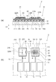
- (A) And (b) is a figure which illustrates the humidity detection apparatus which concerns on this embodiment.
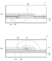
- (A) And (b) is a figure which illustrates the humidity detection apparatus which concerns on a reference example.
- (A) And (b) is a figure which illustrates the simulation result of electric field distribution.
- (A) And (b) is a figure which illustrates the simulation result of electric field distribution. It is a figure which illustrates the comparison result of drift characteristics.
- (A) And (b) is sectional drawing which shows the application example of a humidity detection apparatus.
- (A) And (b) is sectional drawing which shows the application example of a humidity detection apparatus.
- FIG. 1A and 1B are diagrams illustrating a humidity detection device according to the present embodiment.
- FIG. 1A shows a cross-sectional view of the humidity detection device 1
- FIG. 1B shows a plan view of the humidity detection device 1.
- the cross-sectional view shown in FIG. 1A is a cross-sectional view taken along line AA shown in FIG.
- the humidity detection device 1 is a device that detects the humidity of outside air as an electrical signal, and includes an insulating layer 30 provided on a base material 50, a detection unit 10, and a reference. Unit 20 and common wiring 70.
- the humidity detection device 1 detects humidity based on a capacity difference between the detection unit 10 and the reference unit 20.
- the base material 50 for example, silicon is used.
- An insulating layer 30 made of, for example, silicon oxide is formed on the main surface 50 a of the base material 50, and the detection unit 10 and the reference unit 20 are formed side by side on the insulating layer 30.
- a pad electrode 15 that is electrically connected to the detection unit 10 and the reference unit 20 is provided on the insulating layer 30.
- the detection unit 10 includes a first detection electrode 110 provided on the insulating layer 30, a detection dielectric unit 130 provided so as to surround the first detection electrode 110, and a detection dielectric unit 130. And a second electrode for detection 120 provided so as to surround the outer periphery.
- a capacitance in which the detection first electrode 110, the detection dielectric portion 130, and the detection second electrode 120 are stacked in this order in the first direction D1 orthogonal to the main surface 50a is configured.
- a refractory metal material such as ruthenium (Ru) or tantalum (Ta) is suitably used as a conductive material that is not easily oxidized.
- ruthenium (Ru) or tantalum (Ta) is suitably used as a conductive material that is not easily oxidized.
- polyimide resin is used for the detection dielectric portion 130.
- the second electrode 120 for detection is provided with a plurality of through holes 120h at predetermined intervals. External moisture reaches the detection dielectric portion 130 through the through-hole 120h.
- the dielectric constant of the detection dielectric portion 130 changes according to the amount of moisture contained in the detection dielectric portion 130. Thereby, the electrostatic capacitance between the 1st electrode 110 for a detection and the 2nd electrode 120 for a detection changes, and humidity can be detected based on the changed electrostatic capacitance.
- the reference unit 20 has a stacked structure similar to that of the detection unit 10. That is, the reference unit 20 includes a reference first electrode 210 provided on the insulating layer 30, a reference dielectric unit 230 provided so as to surround the reference first electrode 210, and a reference dielectric. A second reference electrode 220 provided so as to surround the portion 230.
- the capacitor in which the first reference electrode 210, the reference dielectric portion 230, and the second reference electrode 220 are stacked in this order in the first direction D1 is formed.
- the reference second electrode 220 is not provided with a through hole, and the reference dielectric portion 230 is surrounded by the reference second electrode 220, so that almost no moisture from the outside enters the reference portion 20. Absent. For this reason, the dielectric constant of the reference dielectric part 230 hardly changes. Therefore, the capacitance of the reference portion 20 constituted by the first reference electrode 210, the second reference electrode 220, and the reference dielectric portion 230 is substantially constant.
- the relative humidity can be detected from the difference between the output voltage based on the electrostatic capacity in the reference unit 20 and the output voltage based on the electrostatic capacity in the detection unit 10.
- a protective layer 40 may be provided around the detection unit 10 and the reference unit 20 on the insulating layer 30.
- a material having higher moisture resistance than the insulating layer 30 For example, silicon nitride (SiN) is used for the protective layer 40. Accordingly, moisture that enters the detection dielectric portion 130 and the reference dielectric portion 230 from the side surface of the detection second electrode 120 and the side surface of the reference second electrode 220 can be suppressed.
- the common wiring 70 is provided between the detection unit 10 and the reference unit 20.
- the common wiring 70 is provided so as to be electrically connected to the detection first electrode 110 and the reference first electrode 210 via the insulating layer 30. That is, the common wiring 70 is provided between the main surface 50 a of the base material 50 and the surface 30 a opposite to the main surface 50 a of the insulating layer 30.
- the common wiring 70, the first electrode for detection 110, and the first electrode for reference 210 are located in different layers. Therefore, the first electrode for detection 110 provided on the insulating layer 30 and the first electrode for reference 210 are brought into conduction by the common wire 70 through the through hole provided at the end of the common wire 70. .
- a detection lead-out wiring 12 is provided between the detection second electrode 120 and the pad electrode 15, and a reference lead-out wiring 13 is provided between the reference second electrode 220 and the pad electrode 15.
- the detection lead-out wiring 12 and the reference lead-out wiring 13 are provided in the insulating layer 30.
- the detection lead-out wiring 12 and the reference lead-out wiring 13 are preferably provided in the same layer as the common wiring 70. Thereby, the detection lead-out wiring 12, the reference lead-out wiring 13, and the common wiring 70 can be formed in the same process.
- the common wiring 70 is provided through the insulating layer 30, the detection second electrode 120 and the reference second electrode 220 are recessed ( The common wiring 70 can be provided without providing an opening. Since it is not necessary to provide a recess (opening) for the common wiring 70 to pass through the second detection electrode 120 and the second reference electrode 220, the outer peripheral position of the second detection electrode 120 is detected over the entire outer periphery. It is outside the outer peripheral position of the dielectric part 130 for use. Further, the outer peripheral position of the reference second electrode 220 is outside the outer peripheral position of the reference dielectric portion 230 over the entire outer periphery.
- the second detection electrode 120 can surround the entire detection dielectric portion 130 except for the through-hole 120h, and the second reference electrode 220 can surround the entire reference dielectric portion 230. Can do. Specifically, when viewed from the stacking direction (first direction D1), the entire detection dielectric portion 130 is covered by the detection second electrode 120 except for the through-hole 120h, and the reference dielectric portion 230 The whole is covered with the second reference electrode 220. Therefore, it is possible to suppress the occurrence of unnecessary leakage electric fields at the ends of the second detection electrode 120 and the second reference electrode 220.
- FIG. 2A and 2B are diagrams illustrating a humidity detection device according to a reference example.
- 2A shows a cross-sectional view of the humidity detection device 1
- FIG. 1B shows a plan view of the humidity detection device 2.
- the cross-sectional view shown in FIG. 2 (a) is a cross-sectional view taken along the line BB shown in FIG. 2 (b).
- the common wiring 75 is provided in the same layer as the first electrode 110 for detection and the first electrode 210 for reference. That is, the common wiring 75 is provided on the insulating layer 30 so as to connect between the first detection electrode 110 and the first reference electrode 210.
- the end of the second electrode for detection 120 and the end of the second electrode for reference 220 are prevented so that the common wiring 75, the second electrode for detection 120, and the second electrode for reference 220 are not short-circuited.
- the part is provided with a recess 90.
- the recess 90 is provided at a position overlapping the common wiring 75 in the first direction D1.
- the detection dielectric portion 130 and the reference dielectric portion 230 are exposed at the position of the recess 90, so that the portion other than the through hole 120h is covered with the protective layer 40. ing.
- the protective layer 40 covers the edge of the through hole 120h, the capacitance adjusting hole 220h may be provided in the reference second electrode 220 in order to reflect the change in the dielectric constant at this portion in the reference unit 20.
- FIG. 3A to FIG. 4B are diagrams illustrating simulation results of electric field distribution.
- FIGS. 3A and 3B show the simulation results of the electric field distribution at the center portion of the reference portion 20, and FIGS. 4A and 4B show the electric field distribution at the end portion of the reference portion 20. Simulation results are shown.
- (A) is the simulation result of the humidity detection apparatus 1 which concerns on this embodiment, respectively
- (b) is the simulation result of the humidity detection apparatus 2 which concerns on a reference example.
- a capacity adjustment hole 220h is provided in the central portion of the reference second electrode 220.
- the electric field distribution in the central portion of the reference second electrode 220 of the humidity detecting device 2 according to the reference example causes an electric field to leak at the end of the capacity adjustment hole 220h, and the protective layer 40 is also affected by the electric field. (See FIG. 3B).
- the capacitance adjusting hole 220h is not provided in the central portion of the second reference electrode 220, and is flat. For this reason, the electric field distribution in the central portion of the reference second electrode 220 of the humidity detection device 1 according to the present embodiment is uniform.
- a recess 90 for preventing a short circuit with the common wiring 70 is provided at the end of the reference second electrode 220.
- an electric field leaks in the vicinity of the recess 90, and the protective layer 40 is also affected by the electric field.
- no recess is provided at the end of the reference second electrode 220, and the end of the reference dielectric portion 230 is not provided. It is provided to cover up to.
- FIG. 3 and 4 show electric field distribution simulation results at the reference unit 20, but the electric field distribution at the end of the second detection electrode 120 is the same as that of the reference unit 20. Further, the electric field distribution in the vicinity of the through hole 120h is the same as the electric field distribution in the vicinity of the capacity adjustment hole 220h shown in FIG. 3B, but in this embodiment, the protection is provided on the detection second electrode 120. Since the layer 40 is not provided, it is not necessary to consider the influence of the electric field on the protective layer 40 in the vicinity of the through hole 120h.
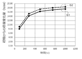
- FIG. 5 is a diagram illustrating a comparison result of drift characteristics.
- the horizontal axis represents time (hr), and the vertical axis represents the amount of change in capacity (% RH) from the initial measurement.
- FIG. 5 shows a drift characteristic G1 of the humidity detection device 1 according to the present embodiment and a drift characteristic G2 of the humidity detection device 2 according to the reference example.
- Drift characteristics G1 and G2 indicate changes in measured values of the humidity detection apparatuses 1 and 2 from the start of measurement until 1000 hours have passed. Due to the difference in structure as described above, the humidity detection drift amount in the humidity detection device 1 according to the present embodiment is suppressed by about 1% with respect to the humidity detection drift amount in the humidity detection device 2 according to the reference example. Is done.
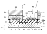
- FIG. 6 to 8B are cross-sectional views showing application examples of the humidity detection device.
- a frame portion 60 is provided around the detection unit 10.
- the frame portion 60 is formed, for example, by etching silicon into a frame shape, and is connected to the base material 50 via an adhesive 65.
- the frame portion 60 can be configured using the workability and hardness of silicon.
- the 7A has a structure in which the adhesive 65 for attaching the frame part 60 on the reference part 20 is not provided. Since the adhesive 65 is not provided on the reference unit 20, the capacity variation of the reference unit 20 can be suppressed. That is, the electric field formed by applying a voltage to the first reference electrode 210 and the second reference electrode 220 extends not only on the reference dielectric portion 230 side but also above the reference second electrode 220. Since the adhesive 65 is not provided above the second reference electrode 220, it is not affected by the change in the dielectric constant of the adhesive 65 due to the expansion of the electric field. can do.
- an opening 601 of the frame 60 is provided above the detection unit 10 and the reference unit 20. That is, the frame part 60 is not provided above the reference part 20 as well as above the detection part 10. As a result, the environment (structure) above the reference unit 20 matches the environment (structure) above the detection unit 10, and relative humidity can be calculated with high accuracy.
- the 8A has a structure in which the adhesive 65 for attaching the frame portion 60 on the reference portion 20 is not provided, similarly to the humidity detection device 1B.
- the difference from the humidity detection device 1 ⁇ / b> B is that an adhesive 65 is provided between the reference unit 20 and the detection unit 10.
- an adhesive 65 is provided between the reference unit 20 and the detection unit 10.
- each of the detection unit 10 and the reference unit 20 has a structure separated from the adhesive 65 for attaching the frame unit 60.
- the pillar 603 is provided on the frame 60, and when the frame 60 is attached, the detection unit 10 and the reference unit 20 are surrounded by the pillar 603.
- the adhesive 65 is attached to a portion without the pillar 603 except on the detection unit 10 and the reference unit 20. With such a structure, the detection unit 10 and the reference unit 20 and the adhesive 65 are not adjacent to each other.
- the adhesive 65 is made of a resin such as polyimide, it has a hygroscopic property.
- the dielectric constant of the adhesive 65 changes as the adhesive 65 absorbs moisture.
- the detection unit 10 and the reference unit 20 are easily affected by the change in the dielectric constant of the adhesive 65.
- the detection unit 10 and the reference unit 20 are separated from the adhesive 65 by the pillar 603, so that it is difficult to be affected by the dielectric constant of the adhesive 65, and the humidity detection is highly accurate. Can be performed.
- the humidity detectors 1, 1B, 1C, 1D, and 1E that can suppress the drift of the measurement value of the humidity detection and can perform stable measurement. It becomes possible.
- the detection method of the humidity in the detection unit 10 and the reference unit 20 may be a method of measuring and detecting the capacitance as described above, or a method of detecting the humidity by measuring a resistance value.
- the detection method of the humidity in the detection unit 10 and the reference unit 20 may be a method of measuring and detecting the capacitance as described above, or a method of detecting the humidity by measuring a resistance value.
- ruthenium (Ru) etc. as an electrode material
- a protective material such as a silicone gel material may be provided so as to cover the detection unit 10 and the reference unit 20.
Landscapes
- Chemical & Material Sciences (AREA)
- Chemical Kinetics & Catalysis (AREA)
- Electrochemistry (AREA)
- Physics & Mathematics (AREA)
- Health & Medical Sciences (AREA)
- Life Sciences & Earth Sciences (AREA)
- Analytical Chemistry (AREA)
- Biochemistry (AREA)
- General Health & Medical Sciences (AREA)
- General Physics & Mathematics (AREA)
- Immunology (AREA)
- Pathology (AREA)
- Investigating Or Analyzing Materials By The Use Of Electric Means (AREA)
- Investigating Or Analyzing Materials By The Use Of Fluid Adsorption Or Reactions (AREA)
Abstract
本発明の一態様は、湿度検知の測定値のドリフトを抑制して、安定した測定を行うことができる湿度検知装置であって、基材の主面上に設けられた絶縁層と、絶縁層の上に設けられた参照部と、絶縁層の上に設けられ、参照部と並置された検知部と、参照部と検知部との間に設けられた共通配線と、を備える。参照部は、基材の主面上に設けられた参照用第1電極と、参照用第1電極を包囲するように設けられた参照用誘電体部と、参照用誘電体部を包囲するように設けられた参照用第2電極と、を有する。検知部は、基材の主面上に設けられた検知用第1電極と、検知用第1電極を包囲するように設けられた検知用誘電体部と、検知用誘電体部を包囲するように設けられ、貫通孔が設けられた検知用第2電極と、を有する。共通配線は、絶縁層内を経由して参照用第1電極および検知用第1電極と導通するよう設けられる。
Description
本発明は湿度検知装置に関し、より詳しくは、参照部を基準として検知部で湿度の検知を行う湿度検知装置に関するものである。
湿度検知装置として、2つの電極間に誘電体部を設け、誘電体部の電気的特性(静電容量、電気抵抗)の変化に基づき湿度を検知する構成が知られている。例えば、静電容量の変化によって湿度を検知する装置(容量式の湿度検知装置)では、外気の湿度の影響を受けない参照用容量部(参照部)と、外気の湿度によって容量が変化する湿度検知用容量部(検知部)とを備えている。
参照部は外気から湿気が浸入しないような構造になっており、湿度にかかわらず一定の容量を構成している。一方、検知部は外気から湿気が浸入できる構造になっており、湿度に応じて容量が変化する構成となっている。このような容量式の湿度検知装置では、検知部からの出力電圧と、参照部からの出力電圧との差分に基づいて相対湿度が算出される。
特許文献1には、上部電極と上部電極の接続端子との接続性の向上を図り、品質および信頼性を向上させる感湿素子が開示される。この感湿素子は、基板上に上部電極の接続端子を設けるとともに、この上部電極接続端子から感湿膜の段差部を被覆する形で一層の金属膜が感湿膜上まで形成されている。
特許文献2には、上側電極と上側電極用電極端子との間および上側電極用電極端子、下側電極用電極端子とリード線との間の電気的接続性の向上を図り、品質および信頼性を向上させる湿度検出素子が開示される。この湿度検出素子では、電極用パッド上に、上側電極の一端部からなる延在部を積層形成して上側電極用電極端子を構成している。
特許文献3、4には、参照部(基準部)の下部電極と検知部(センサ部)の下部電極とを基板上で導通させた湿度センサが開示される。
参照部および検知部を備えた湿度検知装置において、参照部の下部電極と検知部の下部電極を導通させる共通配線を基板上に設ける場合、上部電極と共通配線との接触を避けるため上部電極に凹部(開口)を設けておく必要がある。上部電極に凹部が設けられていると、凹部の端部と下部電極との間で漏れ電界が生じ、測定値のドリフトの要因となる。
本発明は、湿度検知の測定値のドリフトを抑制して、安定した測定を行うことができる湿度検知装置を提供することを目的とする。
上記課題を解決するため、本発明の一態様は、基材の主面上に設けられた絶縁層と、絶縁層の上に設けられた検知部と、絶縁層の上に設けられ、検知部と並置された参照部と、検知部と参照部との間に設けられた共通配線と、を備えた湿度検知装置である。
検知部は、絶縁層の上に設けられた検知用第1電極と、検知用第1電極を包囲するように設けられた検知用誘電体部と、検知用誘電体部を包囲するように設けられ、貫通孔が設けられた検知用第2電極と、を有する。
参照部は、絶縁層の上に設けられた参照用第1電極と、参照用第1電極を包囲するように設けられた参照用誘電体部と、参照用誘電体部を包囲するように設けられた参照用第2電極と、を有する。
共通配線は、絶縁層内を経由して検知用第1電極および参照用第1電極と導通するように設けられる。
検知部は、絶縁層の上に設けられた検知用第1電極と、検知用第1電極を包囲するように設けられた検知用誘電体部と、検知用誘電体部を包囲するように設けられ、貫通孔が設けられた検知用第2電極と、を有する。
参照部は、絶縁層の上に設けられた参照用第1電極と、参照用第1電極を包囲するように設けられた参照用誘電体部と、参照用誘電体部を包囲するように設けられた参照用第2電極と、を有する。
共通配線は、絶縁層内を経由して検知用第1電極および参照用第1電極と導通するように設けられる。
このような構成によれば、共通配線が絶縁層内を経由しているため、検知用第2電極および参照用第2電極に凹部(開口)を設けることなく共通配線を設けることができる。これにより、検知用第2電極は検知用誘電体部の全体を包囲することができ、参照用第2電極は参照用誘電体部の全体を包囲することができ、それぞれの第2電極の端部での不要な漏れ電界の発生を抑制することができる。上記湿度検知装置は、一具体例において、積層方向からみたときに、貫通孔を除き、検知用誘電体部の全体は、検知用第2電極により覆われ、参照用誘電体部の全体は、参照用第2電極により覆われている。
上記湿度検知装置において、参照用第2電極には貫通孔が設けられていないことが好ましい。これにより、貫通孔による参照用第1電極と参照用第2電極との間での不要な漏れ電界は発生しない。
上記湿度検知装置において、参照用第2電極と導通しする参照用引き出し配線と、検知用第2電極と導通する検知用引き出し配線と、をさらに備えており、検知用引き出し配線および参照用引き出し配線が、絶縁層内に設けられていてもよい。
上記湿度検知装置において、参照用引き出し配線および検知用引き出し配線は、共通配線と同層に設けられていることが好ましい。これにより、検知用引き出し配線、参照用引き出し配線および共通配線を同一工程で形成することができる。
上記湿度検知装置において、絶縁層上における検知部および参照部の周囲には、絶縁層よりも耐湿性の高い保護層が設けられていてもよい。これにより、参照用第2電極の側面および検知用第2電極の側面から誘電体部へ浸入する湿気を抑制することができる。
上記湿度検知装置において、検知用第2電極の上に保護層は設けられていないことが好ましい。これにより、検知用第2電極の貫通孔の近傍での漏れ電界の影響が保護層に及ばず、測定値の精度が向上する。
本発明によれば、湿度検知の測定値のドリフトを抑制して、安定した測定を行うことができる湿度検知装置を提供することが可能になる。
以下、本発明の実施形態を図面に基づいて説明する。なお、以下の説明では、同一の部材には同一の符号を付し、一度説明した部材については適宜その説明を省略する。
(湿度検知装置の構成)
図1(a)および(b)は、本実施形態に係る湿度検知装置を例示する図である。
図1(a)には湿度検知装置1の断面図が示され、図1(b)には湿度検知装置1の平面図が示される。図1(a)に示す断面図は、図1(b)に示すA-A線断面図である。
図1(a)および(b)は、本実施形態に係る湿度検知装置を例示する図である。
図1(a)には湿度検知装置1の断面図が示され、図1(b)には湿度検知装置1の平面図が示される。図1(a)に示す断面図は、図1(b)に示すA-A線断面図である。
図1に示すように、本実施形態に係る湿度検知装置1は外気の湿度を電気信号として検知する装置であり、基材50の上に設けられた絶縁層30と、検知部10と、参照部20と、共通配線70と、を備える。湿度検知装置1は、検知部10と参照部20との容量差に基づいて湿度を検知する。
基材50としては、例えばシリコンが用いられる。基材50の主面50a上には例えば酸化シリコンの絶縁層30が形成されており、この絶縁層30の上に並置して検知部10および参照部20が形成される。また、絶縁層30の上には検知部10および参照部20と導通するパッド電極15が設けられる。
検知部10は、絶縁層30の上に設けられた検知用第1電極110と、検知用第1電極110を包囲するように設けられた検知用誘電体部130と、検知用誘電体部130を包囲するように設けられた検知用第2電極120と、を有する。これにより、主面50aと直交する第1方向D1に、検知用第1電極110、検知用誘電体部130および検知用第2電極120がこの順で積層された容量が構成される。
検知用第1電極110および検知用第2電極120には、酸化しにくい導電材料として、例えばルテニウム(Ru)、タンタル(Ta)などの高融点金属系材料が好適に用いられる。また、検知用誘電体部130には、例えばポリイミド系樹脂が用いられる。
検知用第2電極120には、所定の間隔で複数の貫通孔120hが設けられる。この貫通孔120hを通じて外部の湿気が検知用誘電体部130まで到達する。検知用誘電体部130に含まれる水分量に応じて検知用誘電体部130の誘電率が変化する。これにより、検知用第1電極110と検知用第2電極120との間の静電容量が変化して、変化した静電容量に基づき湿度を検知することができる。
参照部20は、検知部10と同様な積層構造を有する。すなわち、参照部20は、絶縁層30の上に設けられた参照用第1電極210と、参照用第1電極210を包囲するように設けられた参照用誘電体部230と、参照用誘電体部230を包囲するように設けられた参照用第2電極220と、を有する。
これにより、第1方向D1に、参照用第1電極210、参照用誘電体部230および参照用第2電極220がこの順で積層された容量が構成される。参照用第2電極220には貫通孔は設けられておらず、参照用第2電極220で参照用誘電体部230を包囲していることから、参照部20には外部からの湿気がほとんど入らない。このため、参照用誘電体部230の誘電率はほとんど変化しない。したがって、参照用第1電極210、参照用第2電極220および参照用誘電体部230によって構成される参照部20の静電容量はほぼ一定となる。この参照部20での静電容量に基づく出力電圧と、検知部10での静電容量に基づく出力電圧との差分から相対湿度を検知することができる。
絶縁層30の上における検知部10および参照部20の周囲には、保護層40が設けられていてもよい。保護層40を設ける場合、絶縁層30よりも耐湿性の高い材料を用いることが好ましい。保護層40には、例えば窒化シリコン(SiN)が用いられる。これにより、検知用第2電極120の側面および参照用第2電極220の側面から検知用誘電体部130および参照用誘電体部230へ浸入する湿気を抑制することができる。
共通配線70は、検知部10と参照部20との間に設けられる。本実施形態では、共通配線70は、絶縁層30内を経由して検知用第1電極110および参照用第1電極210と導通するように設けられる。すなわち、共通配線70は、基材50の主面50aと、絶縁層30の主面50aとは反対側の面30aとの間に設けられる。
共通配線70と、検知用第1電極110および参照用第1電極210とは、互いに異なるレイヤ(層)に位置する。したがって、共通配線70の端部に設けられたスルーホールを介して絶縁層30の上に設けられた検知用第1電極110と参照用第1電極210とが共通配線70によって導通する状態となる。
また、検知用第2電極120とパッド電極15との間には検知用引き出し配線12が設けられ、参照用第2電極220とパッド電極15との間には参照用引き出し配線13が設けられる。この検知用引き出し配線12および参照用引き出し配線13は、絶縁層30内に設けられている。検知用引き出し配線12および参照用引き出し配線13は、共通配線70と同層に設けられていることが好ましい。これにより、検知用引き出し配線12、参照用引き出し配線13および共通配線70を同一工程で形成することができる。
上記のように、本実施形態に係る湿度検知装置1では、共通配線70が絶縁層30内を経由して設けられているため、検知用第2電極120および参照用第2電極220に凹部(開口)を設けることなく共通配線70を設けることができる。検知用第2電極120および参照用第2電極220に、共通配線70を通すための凹部(開口)を設ける必要がないため、検知用第2電極120の外周位置は、外周の全周にわたり検知用誘電体部130の外周位置よりも外側となる。また、参照用第2電極220の外周位置は、外周の全周にわたり参照用誘電体部230の外周位置よりも外側となる。
これにより、検知用第2電極120は貫通孔120hを除き、検知用誘電体部130の全体を包囲することができ、参照用第2電極220は参照用誘電体部230の全体を包囲することができる。具体的には、積層方向(第1方向D1)からみたときに、貫通孔120hを除き、検知用誘電体部130の全体が検知用第2電極120により覆われ、参照用誘電体部230の全体が参照用第2電極220により覆われている。したがって、検知用第2電極120および参照用第2電極220のそれぞれの端部での不要な漏れ電界の発生を抑制することができる。
図2(a)および(b)は、参考例に係る湿度検知装置を例示する図である。
図2(a)には湿度検知装置1の断面図が示され、図1(b)には湿度検知装置2の平面図が示される。図2(a)に示す断面図は、図2(b)に示すB-B線断面図である。
図2(a)には湿度検知装置1の断面図が示され、図1(b)には湿度検知装置2の平面図が示される。図2(a)に示す断面図は、図2(b)に示すB-B線断面図である。
参考例に係る湿度検知装置2では、共通配線75が、検知用第1電極110および参照用第1電極210と同層に設けられる。すなわち、共通配線75は、絶縁層30の上において検知用第1電極110と参照用第1電極210との間を接続するように設けられる。
このような配線構造の場合、共通配線75と検知用第2電極120および参照用第2電極220とが短絡しないように、検知用第2電極120の端部および参照用第2電極220の端部には凹部90が設けられる。凹部90は、第1方向D1に共通配線75と重なる位置に設けられている。この凹部90の位置に合わせて共通配線75が設けられることで、共通配線75と検知用第2電極120および参照用第2電極220との距離が保たれ、両者の短絡を防止することができる。
また、参考例に係る湿度検知装置2では、凹部90の位置において検知用誘電体部130および参照用誘電体部230が露出することから、貫通孔120h以外の部分を保護層40で覆うようにしている。また、貫通孔120hの縁に保護層40が被ることから、この部分での誘電率変化分を参照部20に反映するため、参照用第2電極220に容量調整孔220hを設ける場合がある。
本実施形態に係る湿度検知装置1と、参考例に係る湿度検知装置2とでは、このような構造の相違から電界分布に差が生じる。
図3(a)~図4(b)は電界分布のシミュレーション結果を例示する図である。
図3(a)および(b)には参照部20の中央部分での電界分布のシミュレーション結果が示され、図4(a)および(b)には参照部20の端部での電界分布のシミュレーション結果が示される。それぞれ(a)が本実施形態に係る湿度検知装置1のシミュレーション結果であり、(b)が参考例に係る湿度検知装置2のシミュレーション結果である。
図3(a)~図4(b)は電界分布のシミュレーション結果を例示する図である。
図3(a)および(b)には参照部20の中央部分での電界分布のシミュレーション結果が示され、図4(a)および(b)には参照部20の端部での電界分布のシミュレーション結果が示される。それぞれ(a)が本実施形態に係る湿度検知装置1のシミュレーション結果であり、(b)が参考例に係る湿度検知装置2のシミュレーション結果である。
図3(b)に示すように、参考例に係る湿度検知装置2では、参照用第2電極220の中央部分に容量調整孔220hが設けられている。このため、参考例に係る湿度検知装置2の参照用第2電極220の中央部分の電界分布は、容量調整孔220hの端部において電界の漏れが生じ、保護層40にも電界の影響が及ぶ(図3(b)参照)。一方、図3(a)に示すように、本実施形態に係る湿度検知装置1では、参照用第2電極220の中央部分に容量調整孔220hは設けられておらず、フラットである。このため、本実施形態に係る湿度検知装置1の参照用第2電極220の中央部分での電界分布は一様となる。
また、図4(b)に示すように、参考例に係る湿度検知装置2では、参照用第2電極220の端部に共通配線70との短絡を防止するための凹部90が設けられている。このため、参考例に係る湿度検知装置2の参照用第2電極220の端部の電界分布は、凹部90近傍において電界の漏れが生じ、保護層40にも電界の影響が及ぶ。一方、図4(a)に示すように、本実施形態に係る湿度検知装置1では、参照用第2電極220の端部に凹部が設けられておらず、参照用誘電体部230の端部まで覆うように設けられている。このため、参照用第1電極210の端部や参照用第2電極220の端部での電界の漏れが少ない。特に、本実施形態に係る湿度検知装置1では、参照用第2電極220の上に保護層40が設けられていないため、保護層40への電界の影響を考慮せずに済む。
図3および図4では、参照部20での電界分布のシミュレーション結果を示しているが、検知用第2電極120の端部での電界分布は参照部20と同様である。また、貫通孔120hの近傍での電界分布は、図3(b)に示す容量調整孔220hの近傍での電界分布と同様であるが、本実施形態では検知用第2電極120の上に保護層40が設けられていないため、貫通孔120hの近傍での保護層40への電界の影響を考慮せずに済む。
図5は、ドリフト特性の比較結果を例示する図である。
図5の横軸は時間(hr)、縦軸は測定初期からの容量変化量(%RH)である。
図5には、本実施形態に係る湿度検知装置1のドリフト特性G1と、参考例に係る湿度検知装置2のドリフト特性G2とが示される。ドリフト特性G1およびG2は、湿度検知装置1および2について測定開始から1000時間を経過するまでの測定値の変化を示している。上記のような構造の相違によって、本実施形態に係る湿度検知装置1での湿度検知のドリフト量は、参考例に係る湿度検知装置2での湿度検知のドリフト量に対して約1%程度抑制される。
図5の横軸は時間(hr)、縦軸は測定初期からの容量変化量(%RH)である。
図5には、本実施形態に係る湿度検知装置1のドリフト特性G1と、参考例に係る湿度検知装置2のドリフト特性G2とが示される。ドリフト特性G1およびG2は、湿度検知装置1および2について測定開始から1000時間を経過するまでの測定値の変化を示している。上記のような構造の相違によって、本実施形態に係る湿度検知装置1での湿度検知のドリフト量は、参考例に係る湿度検知装置2での湿度検知のドリフト量に対して約1%程度抑制される。
(適用例)
図6~図8(b)は、湿度検知装置の適用例を示す断面図である。
図6に示す適用例では、検知部10の周囲に枠部60が設けられている。枠部60は、例えばシリコンをエッチングして枠型に形成したものであり、接着剤65を介して基材50上に接続される。枠部60としてシリコンを用いることで、シリコンの加工性および硬さを利用して枠部60を構成することができる。この枠部60の開口601内に検知部10が配置されることで、外部の湿気が開口601から検知用第2電極120の貫通孔120hを介して検知用誘電体部130に取り込まれる。検知用誘電体部130に取り込まれた湿気に応じて検知用誘電体部130の誘電率が変化し、この誘電率に基づき湿度を検知することができる。
図6~図8(b)は、湿度検知装置の適用例を示す断面図である。
図6に示す適用例では、検知部10の周囲に枠部60が設けられている。枠部60は、例えばシリコンをエッチングして枠型に形成したものであり、接着剤65を介して基材50上に接続される。枠部60としてシリコンを用いることで、シリコンの加工性および硬さを利用して枠部60を構成することができる。この枠部60の開口601内に検知部10が配置されることで、外部の湿気が開口601から検知用第2電極120の貫通孔120hを介して検知用誘電体部130に取り込まれる。検知用誘電体部130に取り込まれた湿気に応じて検知用誘電体部130の誘電率が変化し、この誘電率に基づき湿度を検知することができる。
図7(a)に示す湿度検知装置1Bでは、参照部20の上に枠部60を取り付けるための接着剤65が設けられていない構造を有する。参照部20の上に接着剤65が設けられていないことで、参照部20の容量変動を抑制することができる。すなわち、参照用第1電極210および参照用第2電極220への電圧印加によって形成される電界は、参照用誘電体部230側のほか、参照用第2電極220の上方にも拡がる。参照用第2電極220の上方に接着剤65が設けられていないことで、この電界の拡がりによる接着剤65での誘電率変化の影響を受けずに済むため、参照部20の容量変動を抑制することができる。
図7(b)に示す湿度検知装置1Cでは、検知部10および参照部20の上方に枠部60の開口601が設けられている。すなわち、検知部10の上方のみならず、参照部20の上方にも枠部60が設けられていない。これにより、参照部20の上方の環境(構造)が、検知部10の上方の環境(構造)と合致して、相対的な湿度を精度良く演算することが可能となる。
図8(a)に示す湿度検知装置1Dでは、湿度検知装置1Bと同様に、参照部20の上に枠部60を取り付けるための接着剤65が設けられていない構造を有する。湿度検知装置1Bとの相違は、参照部20と検知部10との間に接着剤65が設けられている点である。このような構造により、湿度検知装置1Bと同様に、参照部20の上方への電界の拡がりによる接着剤65での誘電率変化の影響を受けずに済む。さらに、参照部20の周辺が接着剤65によって囲まれているため、参照部20へのパーティクルの付着を防止することができる。これにより、接着剤65やパーティクル付着による参照部20の容量変動を抑制することができる。
図8(b)に示す湿度検知装置1Eでは、検知部10および参照部20のそれぞれについて、枠部60を取り付けるための接着剤65と分離した構造を有する。例えば、枠部60にピラー603を設け、枠部60を取り付ける際、ピラー603によって検知部10および参照部20を囲むようにする。接着剤65は、検知部10および参照部20の上を除くピラー603のない部分に付けられている。このような構造により、検知部10および参照部20と接着剤65とが隣接しないことになる。
接着剤65にはポリイミド等の樹脂が用いられるため、吸湿性を有している。接着剤65の吸湿によって接着剤65の誘電率は変化する。接着剤65と検知部10および参照部20が隣接していると、接着剤65の誘電率変化の影響を検知部10および参照部20で受けやすくなる。湿度検知装置1Eのように、検知部10および参照部20がピラー603によって接着剤65と分離していることで、接着剤65の誘電率片化の影響を受けにくくなり、精度の高い湿度検知を行うことが可能となる。
以上説明したように、本実施形態によれば、湿度検知の測定値のドリフトを抑制して、安定した測定を行うことができる湿度検知装置1、1B、1C、1Dおよび1Eを提供することが可能となる。
なお、上記に本実施形態を説明したが、本発明はこれらの例に限定されるものではない。例えば、検知部10および参照部20における湿度の検出方式は、上記のように容量を測定して検知する方式であってもよいし、抵抗値を測定して湿度を検知する方式であってもよい。また、電極材料としてルテニウム(Ru)などを用いる例を示したが、例えばアルミニウムや銅といった他の導電材料を用いてもよい。パーティクル対策として検知部10および参照部20を覆うようにシリコーン系のゲル材料などの保護材が設けられていてもよい。
また、前述の実施形態に対して、当業者が適宜、構成要素の追加、削除、設計変更を行ったものや、実施形態の構成例の特徴を適宜組み合わせたものも、本発明の要旨を備えている限り、本発明の範囲に含有される。
1,1B,1C,1D,1E…湿度検知装置
2…湿度検知装置
10…検知部
12…検知用引き出し配線
13…参照用引き出し配線
15…パッド電極
20…参照部
30…絶縁層
30a…面
40…保護層
50…基材
50a…主面
60…枠部
65…接着剤
70,75…共通配線
90…凹部
110…検知用第1電極
120…検知用第2電極
120h…貫通孔
130…検知用誘電体部
210…参照用第1電極
220…参照用第2電極
220h…容量調整孔
230…参照用誘電体部
601…開口
603…ピラー
D1…第1方向
G1…ドリフト特性
G2…ドリフト特性
2…湿度検知装置
10…検知部
12…検知用引き出し配線
13…参照用引き出し配線
15…パッド電極
20…参照部
30…絶縁層
30a…面
40…保護層
50…基材
50a…主面
60…枠部
65…接着剤
70,75…共通配線
90…凹部
110…検知用第1電極
120…検知用第2電極
120h…貫通孔
130…検知用誘電体部
210…参照用第1電極
220…参照用第2電極
220h…容量調整孔
230…参照用誘電体部
601…開口
603…ピラー
D1…第1方向
G1…ドリフト特性
G2…ドリフト特性
Claims (7)
- 基材の主面上に設けられた絶縁層と、
前記絶縁層の上に設けられた検知部と、
前記絶縁層の上に設けられ、前記検知部と並置された参照部と、
前記検知部と前記参照部との間に設けられた共通配線と、を備えた湿度検知装置であって、
前記検知部は、
前記絶縁層の上に設けられた検知用第1電極と、
前記検知用第1電極を包囲するように設けられた検知用誘電体部と、
前記検知用誘電体部を包囲するように設けられ、貫通孔が設けられた検知用第2電極と、を有し、
前記参照部は、
前記絶縁層の上に設けられた参照用第1電極と、
前記参照用第1電極を包囲するように設けられた参照用誘電体部と、
前記参照用誘電体部を包囲するように設けられた参照用第2電極と、を有し、
前記共通配線は、
前記絶縁層内を経由して前記検知用第1電極および前記参照用第1電極と導通するように設けられたことを特徴とする湿度検知装置。 - 積層方向からみたときに、
前記貫通孔を除き、前記検知用誘電体部の全体は、前記検知用第2電極により覆われ、
前記参照用誘電体部の全体は、前記参照用第2電極により覆われている、
請求項1に記載の湿度検知装置。 - 前記参照用第2電極には貫通孔が設けられていない、請求項1または請求項2に記載の湿度検知装置。
- 前記検知用第2電極と導通する検知用引き出し配線と、
前記参照用第2電極と導通する参照用引き出し配線と、をさらに備え、
前記検知用引き出し配線および前記参照用引き出し配線は、前記絶縁層内に設けられた、請求項1から請求項3のいずれか一項に記載の湿度検知装置。 - 前記検知用引き出し配線および前記参照用引き出し配線は、前記共通配線と同層に設けられた、請求項4に記載の湿度検知装置。
- 前記絶縁層上における前記検知部および前記参照部の周囲には、前記絶縁層よりも耐湿性の高い保護層が設けられた、請求項1から請求項5のいずれか一項に記載の湿度検知装置。
- 前記検知用第2電極の上に前記保護層は設けられていない、請求項6に記載の湿度検知装置。
Applications Claiming Priority (2)
| Application Number | Priority Date | Filing Date | Title |
|---|---|---|---|
| JP2018050852A JP2021089139A (ja) | 2018-03-19 | 2018-03-19 | 湿度検知装置 |
| JP2018-050852 | 2018-03-19 |
Publications (1)
| Publication Number | Publication Date |
|---|---|
| WO2019181771A1 true WO2019181771A1 (ja) | 2019-09-26 |
Family
ID=67987826
Family Applications (1)
| Application Number | Title | Priority Date | Filing Date |
|---|---|---|---|
| PCT/JP2019/010787 Ceased WO2019181771A1 (ja) | 2018-03-19 | 2019-03-15 | 湿度検知装置 |
Country Status (3)
| Country | Link |
|---|---|
| JP (1) | JP2021089139A (ja) |
| TW (1) | TW201939031A (ja) |
| WO (1) | WO2019181771A1 (ja) |
Citations (3)
| Publication number | Priority date | Publication date | Assignee | Title |
|---|---|---|---|---|
| JPS5437795A (en) * | 1977-08-30 | 1979-03-20 | Matsushita Electric Ind Co Ltd | Moisture detector |
| WO2010113711A1 (ja) * | 2009-03-31 | 2010-10-07 | アルプス電気株式会社 | 容量型湿度センサ及びその製造方法 |
| JP2017067445A (ja) * | 2014-02-17 | 2017-04-06 | アルプス電気株式会社 | 湿度センサ |
-
2018
- 2018-03-19 JP JP2018050852A patent/JP2021089139A/ja active Pending
- 2018-12-14 TW TW107145133A patent/TW201939031A/zh unknown
-
2019
- 2019-03-15 WO PCT/JP2019/010787 patent/WO2019181771A1/ja not_active Ceased
Patent Citations (3)
| Publication number | Priority date | Publication date | Assignee | Title |
|---|---|---|---|---|
| JPS5437795A (en) * | 1977-08-30 | 1979-03-20 | Matsushita Electric Ind Co Ltd | Moisture detector |
| WO2010113711A1 (ja) * | 2009-03-31 | 2010-10-07 | アルプス電気株式会社 | 容量型湿度センサ及びその製造方法 |
| JP2017067445A (ja) * | 2014-02-17 | 2017-04-06 | アルプス電気株式会社 | 湿度センサ |
Also Published As
| Publication number | Publication date |
|---|---|
| TW201939031A (zh) | 2019-10-01 |
| JP2021089139A (ja) | 2021-06-10 |
Similar Documents
| Publication | Publication Date | Title |
|---|---|---|
| FI126999B (en) | Improved pressure sensor | |
| TWI600887B (zh) | 一種改良的壓力感測器結構 | |
| EP2203738B1 (en) | Improved structure for capacitive balancing of integrated relative humidity sensor and manufacturing method | |
| CN105340025B (zh) | 导体组件 | |
| CN103748457A (zh) | 湿度传感器及其制造方法 | |
| US11435310B2 (en) | Humidity sensor | |
| JP4452526B2 (ja) | 歪検出素子及び圧力センサ | |
| JPH0755615A (ja) | 静電容量型力センサ | |
| CN116134625B (zh) | 压力传感器构造、压力传感器装置及压力传感器构造的制造方法 | |
| TW202237524A (zh) | 壓力感測器及操作壓力感測器的方法 | |
| JP5009867B2 (ja) | ガスセンサ | |
| CN116324363A (zh) | 压力传感器用芯片及压力传感器 | |
| TWI746571B (zh) | 應變檢測器及其製造方法 | |
| JP3815771B2 (ja) | 静電容量式ギャップセンサ、及びその信号検出方法 | |
| JP2010147227A (ja) | 電子デバイスパッケージ | |
| JP6970935B2 (ja) | 物理量センサ | |
| JP2021089139A (ja) | 湿度検知装置 | |
| JP2018059713A (ja) | 容量感知型湿度センサ | |
| JP2005127784A (ja) | 非接触電圧測定装置 | |
| JP2019158505A (ja) | 湿度検知装置 | |
| WO2019107282A1 (ja) | 湿度検知装置 | |
| JP5825181B2 (ja) | 湿度センサ | |
| JP2001208780A (ja) | 容量形分圧器 | |
| JP2017090082A (ja) | 圧力検出装置 | |
| WO2022163324A1 (ja) | 歪みセンサ |
Legal Events
| Date | Code | Title | Description |
|---|---|---|---|
| 121 | Ep: the epo has been informed by wipo that ep was designated in this application |
Ref document number: 19771857 Country of ref document: EP Kind code of ref document: A1 |
|
| NENP | Non-entry into the national phase |
Ref country code: DE |
|
| 122 | Ep: pct application non-entry in european phase |
Ref document number: 19771857 Country of ref document: EP Kind code of ref document: A1 |
|
| NENP | Non-entry into the national phase |
Ref country code: JP |