WO2019181648A1 - Procédé de fabrication d'article absorbant et dispositif de fabrication d'article absorbant - Google Patents
Procédé de fabrication d'article absorbant et dispositif de fabrication d'article absorbant Download PDFInfo
- Publication number
- WO2019181648A1 WO2019181648A1 PCT/JP2019/009983 JP2019009983W WO2019181648A1 WO 2019181648 A1 WO2019181648 A1 WO 2019181648A1 JP 2019009983 W JP2019009983 W JP 2019009983W WO 2019181648 A1 WO2019181648 A1 WO 2019181648A1
- Authority
- WO
- WIPO (PCT)
- Prior art keywords
- material coil
- coil
- absorbent article
- rotating shaft
- outer diameter
- Prior art date
Links
Images


Classifications
-
- B—PERFORMING OPERATIONS; TRANSPORTING
- B65—CONVEYING; PACKING; STORING; HANDLING THIN OR FILAMENTARY MATERIAL
- B65H—HANDLING THIN OR FILAMENTARY MATERIAL, e.g. SHEETS, WEBS, CABLES
- B65H23/00—Registering, tensioning, smoothing or guiding webs
- B65H23/02—Registering, tensioning, smoothing or guiding webs transversely
-
- B—PERFORMING OPERATIONS; TRANSPORTING
- B65—CONVEYING; PACKING; STORING; HANDLING THIN OR FILAMENTARY MATERIAL
- B65H—HANDLING THIN OR FILAMENTARY MATERIAL, e.g. SHEETS, WEBS, CABLES
- B65H19/00—Changing the web roll
- B65H19/10—Changing the web roll in unwinding mechanisms or in connection with unwinding operations
- B65H19/18—Attaching, e.g. pasting, the replacement web to the expiring web
- B65H19/1805—Flying splicing, i.e. the expiring web moving during splicing contact
- B65H19/181—Flying splicing, i.e. the expiring web moving during splicing contact taking place on the replacement roll
- B65H19/1821—Flying splicing, i.e. the expiring web moving during splicing contact taking place on the replacement roll the replacement web being accelerated or running prior to splicing contact
-
- A—HUMAN NECESSITIES
- A61—MEDICAL OR VETERINARY SCIENCE; HYGIENE
- A61F—FILTERS IMPLANTABLE INTO BLOOD VESSELS; PROSTHESES; DEVICES PROVIDING PATENCY TO, OR PREVENTING COLLAPSING OF, TUBULAR STRUCTURES OF THE BODY, e.g. STENTS; ORTHOPAEDIC, NURSING OR CONTRACEPTIVE DEVICES; FOMENTATION; TREATMENT OR PROTECTION OF EYES OR EARS; BANDAGES, DRESSINGS OR ABSORBENT PADS; FIRST-AID KITS
- A61F13/00—Bandages or dressings; Absorbent pads
- A61F13/15—Absorbent pads, e.g. sanitary towels, swabs or tampons for external or internal application to the body; Supporting or fastening means therefor; Tampon applicators
- A61F13/15577—Apparatus or processes for manufacturing
-
- B—PERFORMING OPERATIONS; TRANSPORTING
- B65—CONVEYING; PACKING; STORING; HANDLING THIN OR FILAMENTARY MATERIAL
- B65H—HANDLING THIN OR FILAMENTARY MATERIAL, e.g. SHEETS, WEBS, CABLES
- B65H2301/00—Handling processes for sheets or webs
- B65H2301/40—Type of handling process
- B65H2301/41—Winding, unwinding
- B65H2301/415—Unwinding
- B65H2301/41505—Preparing unwinding process
- B65H2301/41508—Preparing unwinding process the web roll being in the unwinding support / unwinding location
- B65H2301/415085—Preparing unwinding process the web roll being in the unwinding support / unwinding location by adjusting / registering the lateral position of the web roll
-
- B—PERFORMING OPERATIONS; TRANSPORTING
- B65—CONVEYING; PACKING; STORING; HANDLING THIN OR FILAMENTARY MATERIAL
- B65H—HANDLING THIN OR FILAMENTARY MATERIAL, e.g. SHEETS, WEBS, CABLES
- B65H2701/00—Handled material; Storage means
- B65H2701/10—Handled articles or webs
- B65H2701/11—Dimensional aspect of article or web
- B65H2701/113—Size
- B65H2701/1133—Size of webs
- B65H2701/11332—Size of webs strip, tape, narrow web
-
- B—PERFORMING OPERATIONS; TRANSPORTING
- B65—CONVEYING; PACKING; STORING; HANDLING THIN OR FILAMENTARY MATERIAL
- B65H—HANDLING THIN OR FILAMENTARY MATERIAL, e.g. SHEETS, WEBS, CABLES
- B65H2701/00—Handled material; Storage means
- B65H2701/10—Handled articles or webs
- B65H2701/18—Form of handled article or web
- B65H2701/184—Wound packages
- B65H2701/1848—Dimensional aspect
- B65H2701/18482—Proportion
- B65H2701/18483—Diameter much larger than width, e.g. audio/video tape bobbin
Definitions
- the present invention relates to an absorbent article manufacturing method and an absorbent article manufacturing apparatus.
- the succeeding material supplied from the succeeding material coil is joined to the preceding material, and the succeeding material is fed.
- the absorbent article manufacturing method which manufactures an absorbent article is already well known (for example, refer patent document 1).
- the materials when joining the preceding material and the succeeding material, the materials may be shifted in the width direction. In such a case, the preceding material and the succeeding material are joined in a state shifted in the width direction. Therefore, there is a problem that the material to be conveyed meanders greatly, or the joining is insufficient and the joining is peeled off during the transportation.
- the present invention has been made in view of the above-described problems, and an object of the present invention is to suppress a shift in joining a preceding material and a succeeding material.
- the main invention for achieving the above object is: Without stopping the feeding of the first material continuously fed from the preceding first material coil, the second material supplied from the succeeding second material coil is joined to the first material, and the second material is fed.
- the absorbent material manufacturing method for manufacturing the absorbent article wherein the first material coil mounting step of mounting the first material coil around which the first material is wound to a first rotating shaft; The second material coil wound around the second material coil is attached to the second rotating shaft, and the first material fed out from the first material coil is driven by the rotation of the first rotating shaft.
- Each of the first material coil and the second material coil has a larger dimension in the outer diameter direction than a dimension in the width direction, and in the first material coil mounting step, a predetermined position in the axial direction of the first rotating shaft.
- a first deformation suppressing member for suppressing deformation in the width direction of the first material coil from both sides of the first material coil in the width direction.
- the second positioning portion provided at a predetermined position in the axial direction of the second rotating shaft and the deformation in the width direction of the second material coil are suppressed in the second material coil mounting step.
- a second deformation suppressing member for attaching the second material coil, the second material coil being sandwiched from both sides in the width direction.
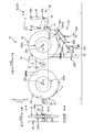
- FIG. 2 is a schematic front view of the material supply apparatus 10 that feeds out the preceding material 3ps from the preceding material coil 3p, and a diagram shown by arrows AA is a schematic side view of the preceding material coil 3p.
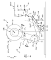
- FIG. 2 is a schematic front view of the material supply apparatus 10 to which the subsequent material coil 3f is attached, and a diagram shown by arrows BB is a schematic side view of the subsequent material coil 3f.
- It is the front schematic diagram of the material supply apparatus 10 which showed the state in which the turret rotation part 20 is turning.
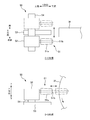
- FIG. 3 is a schematic top view of the correction device 50 shown by the arrow CC in FIG. 2B
- the lower diagram of FIG. 3 is a schematic front view of the correction device 50 shown by the arrow DD in FIG. It is.
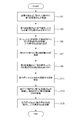
- FIG. 3 is a flowchart showing operation control of the material supply apparatus 10.
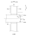
- FIG. 2B is a schematic cross-sectional view of the first positioning portion 25pa and the first pressing plate 25pb attached to the first rotating shaft 25p shown by the EE arrow in FIG. 2A.
- the second material supplied from the succeeding second material coil is joined to the first material, and the second material is fed.
- the absorbent material manufacturing method for manufacturing the absorbent article wherein the first material coil mounting step of mounting the first material coil around which the first material is wound to a first rotating shaft; The second material coil wound around the second material coil is attached to the second rotating shaft, and the first material fed out from the first material coil is driven by the rotation of the first rotating shaft.
- Each of the first material coil and the second material coil has a larger dimension in the outer diameter direction than a dimension in the width direction, and in the first material coil mounting step, a predetermined position in the axial direction of the first rotating shaft.
- a first deformation suppressing member for suppressing deformation in the width direction of the first material coil from both sides of the first material coil in the width direction.
- the second positioning portion provided at a predetermined position in the axial direction of the second rotating shaft and the deformation in the width direction of the second material coil are suppressed in the second material coil mounting step.
- a second deformation suppressing member for attaching the second material coil, the second material coil being sandwiched from both sides in the width direction.
- the first deformation suppressing member is a first pressing plate having a predetermined length in the outer diameter direction of the first rotating shaft, and the predetermined length of the first pressing plate. Is preferably smaller than the radial dimension of the first material coil before being fed out as the first material.
- the first deformation suppressing member is a first pressing plate having a predetermined length in the outer diameter direction of the first rotating shaft, and the predetermined length of the first pressing plate. However, it is desirable that it is larger than 1/3 times the radial dimension of the first material coil before being fed out as the first material.
- the second deformation suppressing member is a second pressing plate having a predetermined length in the outer diameter direction of the second rotating shaft, and the predetermined length of the second pressing plate. Is preferably smaller than the radial dimension of the second material coil before being fed out as the second material.
- the second deformation suppressing member is a second pressing plate having a predetermined length in the outer diameter direction of the second rotating shaft, and the predetermined length of the second pressing plate.
- the first positioning portion has a plate shape having a predetermined length in the outer diameter direction of the first rotating shaft, and the predetermined length of the first positioning portion is It is desirable that it is smaller than the radial dimension of the first material coil before being fed out as the first material.
- the second positioning portion has a plate shape having a predetermined length in the outer diameter direction of the second rotating shaft, and the predetermined length of the second positioning portion is It is desirable that it is smaller than the radial dimension of the second material coil before being fed out as the second material.
- the position where the first material is paid out in the axial direction of the first rotating shaft the position of the outer peripheral surface of the second material coil in the axial direction of the second rotating shaft, From the one side in the axial direction of the second rotary shaft to the other side while contacting the side surface of the outer peripheral portion of the second material coil attached to the second rotary shaft so that It is desirable to have a correction step of correcting the position of the outer peripheral surface in the axial direction of the second rotation axis by a correction device for correction.
- At least one of the correction devices is provided with respect to the second rotating shaft, and includes a moving unit for moving along the outer diameter direction of the second rotating shaft.
- the retracted position is located outside the outer peripheral surface of the second material coil to be attached so that the second material coil to be attached and the correction device do not contact each other.
- the straightening device is retracted, and in the straightening step, the straightening device moves from the retracted position to the inside in the outer diameter direction of the second rotating shaft so that the straightening device contacts the side surface of the outer peripheral portion of the second material coil. It is desirable to move the device.
- the contact portion of the correction device in contact with the second material coil is rotated by a rotating body that can rotate with the direction along the outer diameter direction of the second rotating shaft as the direction of the rotating shaft. It is desirable to be configured.
- the rotating body has a tapered shape in which the outer diameter of the rotating body increases from the inner side to the outer side in the outer diameter direction of the second rotating shaft.
- the straightening device in the straightening step, is a method of straightening the second material coil as a method of performing the straightening over the entire outer periphery of the second material coil.
- a method of rotating the second material coil around the second rotation axis in a state of being fixed at a predetermined position in the circumferential direction; and the correction device in the circumferential direction of the second material coil around the second rotation axis A method of moving the correction device along the circumferential direction of the second material coil in a state in which the second material coil is temporarily unable to rotate. It is desirable to use at least one of the methods.
- Such an absorbent article manufacturing method makes it possible to correct the entire circumference of the succeeding material coil.
- the method includes a detection step of detecting a position of an outer peripheral surface of the second material coil in the axial direction of the second rotation shaft by a detection unit, and in the correction step, the first step Based on information on the deviation between the position where the first material is fed out in the axial direction of the rotating shaft and the position of the outer peripheral surface of the second material coil in the axial direction of the second rotating shaft detected by the detecting step. Therefore, it is desirable to control the correction direction and correction amount of the correction device.
- the end portion of the second material located on the outer peripheral surface of the second material coil is set so that the end portion is not separated from the second material coil. It is desirable that the second material coil is fixed with a bonding material.
- the attachment robot attaches the first material coil to the first rotating shaft by contacting the first material coil, and the attachment Thereafter, the attachment robot attaches the first deformation suppressing member to the first rotating shaft, and attaches the first material coil to the first positioning portion and the first from both sides in the width direction of the first material coil.
- the attachment robot attaches the second material coil to the second positioning shaft by contacting the second material coil, and the attachment of the second material coil Later, the attachment robot attaches the second deformation suppressing member to the second rotation shaft, and the second material coil is applied from both sides in the width direction of the second material coil. It is desirable to interpose between the second deformation suppressing member and the second positioning portion.
- the second material supplied from the succeeding second material coil is joined to the first material, and the second material is fed.
- an absorbent article manufacturing apparatus for manufacturing an absorbent article, wherein a first rotating shaft for attaching the first material coil around which the first material is wound, and the second material are wound. The first material fed out from the first material coil is rotated by the driving rotation of the second rotating shaft by the second rotating shaft for mounting the second material coil and the driving rotation of the first rotating shaft.
- the second material coil has a joint portion that joins the second material to the first material by pressing toward the outer peripheral surface of the second material coil, and the first material coil and the second material coil are , Each width
- the dimension in the outer diameter direction is larger than the dimension in the direction, and a predetermined position in the axial direction of the first rotating shaft for mounting the first material coil sandwiching the first material coil from both sides in the width direction
- a first deformation suppressing member for suppressing deformation in the width direction of the first material coil, and from both sides in the width direction of the second material coil.
- a second positioning part provided at a predetermined position in the axial direction of the second rotating shaft for mounting with the second material coil interposed therebetween, and a second for suppressing deformation in the width direction of the second material coil.
- An apparatus for manufacturing an absorbent article comprising: a deformation suppressing member.
- the absorbent article manufacturing method according to the present embodiment is used for manufacturing absorbent articles in the material supply apparatus 10 of the absorbent article manufacturing apparatus 1. That is, the absorbent article manufacturing method (absorbent article manufacturing apparatus) according to the present embodiment is a method (apparatus) for manufacturing an absorbent article, and is a material supply method (material supply apparatus 10).
- FIG. 1 is a schematic view showing an example of a production line of the absorbent article production apparatus 1.
- FIG. 1 is a diagram in which some descriptions of the material supply device 10 and the processing unit 4 are omitted in order to explain the present invention in an easy-to-understand manner (hereinafter, the description of the omitted parts is also omitted).
- the horizontal direction of the paper surface is defined as the Y direction, and the left side (right side) of the paper surface is referred to as upstream (downstream).
- the absorbent article manufacturing apparatus 1 includes two material supply devices 10 (a material supply first device 10a and a material supply second device 10b) and two processing units 4 (an absorber processing unit 4a and an end cutter 4b). Yes. And the carrying-in of the material 3 to the material supply 1st apparatus 10a and the material supply 2nd apparatus 10b is made with the form of the material coil by which the continuous sheet-like material 3 was wound by the coil shape. That is, in the material supply 1st apparatus 10a and the material supply 2nd apparatus 10b, the continuous sheet-like material 3 is drawn out from the form of the material coil. In addition, the material supply 1st apparatus 10a and the material supply 2nd apparatus 10b are each provided corresponding to the kind of the material 3. FIG.
- a conveyance mechanism conveys the material 3a fed from the material supply first apparatus 10a to the downstream side in the Y direction, and absorber processing on the conveyance path
- the absorber 2 is attached (transferred) onto the material 3a.
- the material 3a in this state is further conveyed downstream in the Y direction, and the material 3b fed from the material supply second device 10b sandwiches the absorber 2, so that various thread rubbers can be attached and joined.
- a conveyance mechanism conveys until it reaches the installation position of the end cutter 4b on a conveyance path
- absorbent article examples include sanitary napkins, unfolded and pants-type disposable diapers, etc., but any article that absorbs the excretion fluid of the wearer may be used.
- an absorbent article is comprised by the absorbent body 2 comprised by the superabsorbent polymer (SAP) etc. which absorb excretion fluid, the liquid-permeable nonwoven fabric etc. which were distribute
- Such a configuration varies depending on the application as exemplified in the absorbent article, and the processing unit 4 and the material supply apparatus 10 provided in the absorbent article manufacturing apparatus 1 are appropriately changed according to the application.
- the material 3 according to the present embodiment has a continuous sheet shape, and is fed out from the form of a material coil around which the continuous sheet-shaped material 3 is wound.
- the material coil is formed by affixing the winding start end portion of the material 3 to the paper tube and spirally winding the material coil, and cuts the continuous sheet-shaped material 3 when reaching a predetermined outer diameter (depending on the type of the material 3). Is formed.
- the terminal part is fixed to the material coil by the bonding material 5 (see FIGS. 2B to 2D). .
- the material 3 is transported from the manufacturing location of the material 3 to the absorbent article manufacturing apparatus 1 in the form of a material coil having a predetermined outer diameter, and is transported into the material supply apparatus 10 after the transport.
- the form of the material coil of the material 3 according to the present embodiment is such that the dimension in the outer diameter direction is larger than the dimension in the width direction of the material coil.
- the dimension is about 10 to 20 times larger than the dimension in the width direction. That is, the dimension in the outer diameter direction is sufficiently larger than the dimension in the width direction of the material coil.
- the material 3 which concerns on this Embodiment is a continuous sheet form comprised with highly flexible nonwoven fabrics, such as an airlaid pulp nonwoven fabric, a spunlace nonwoven fabric, and an air through nonwoven fabric.
- the material coil is made of a highly flexible nonwoven fabric, and the dimension in the outer diameter direction is sufficiently larger than the dimension in the width direction. Therefore, the material coil is easily deformed in the width direction of the material coil due to vibration during transportation of the material coil or due to the weight of the material 3 when the width direction is directed in the vertical direction when the material coil is moved.
- the material supply apparatus 10 will be described with reference to FIGS. 2A and 2B.
- the material supply first device 10a and the material supply second device 10b are provided according to the type of the material 3, but in the present embodiment, the material supply first device 10a and the material supply second device.
- the basic configurations of 10b are the same. Therefore, below, one material supply apparatus 10 is demonstrated.
- FIG. 2A is a schematic front view of the material supply apparatus 10 that feeds out the preceding material 3ps (corresponding to the first material) from the preceding material coil 3p (corresponding to the first material coil), and is a view shown by arrows AA. These are the schematic side views of the preceding material coil 3p.
- the preceding material coil 3p is shown as an outer diameter before the preceding material 3ps is fed out.
- FIG. 2B is a schematic front view of the material supply apparatus 10 to which the succeeding material coil 3f (corresponding to the second material coil) is attached, and the view shown by arrows BB is a schematic side view of the succeeding material coil 3f.
- FIG. 2A is a schematic front view of the material supply apparatus 10 that feeds out the preceding material 3ps (corresponding to the first material) from the preceding material coil 3p (corresponding to the first material coil), and is a view shown by arrows AA.
- FIG. 2A is a schematic front view of the material supply apparatus 10 that feeds
- the X direction and the Y direction are each directed in the horizontal direction
- the Z direction is directed in the vertical direction.
- the left side (right side) of the paper surface is upstream (downstream) with the horizontal direction of the paper surface as the Y direction
- the back side (front side) of the paper surface is up (down) with the vertical direction of the paper surface as the Z direction.
- the horizontal direction of the paper surface is the X direction
- the left side (right side) of the paper surface is called the back (front).
- the positions of the first rotating shaft 25p and the second rotating shaft 25f are represented by a joint portion P1 and a mounting portion P2, as shown in FIGS. 2A and 2B.
- the first rotation shaft 25p is located at the joint P1
- the second rotation shaft 25f is located at the attachment portion P2.
- the attachment is performed.
- the first rotation shaft 25p is positioned at the part P2.
- the material supply device 10 includes a first rotation shaft 25p located at the joint P1, a second rotation shaft 25f located at the attachment portion P2, a first rotation shaft 25p, and a second rotation shaft.
- the turret rotation unit 20 for switching the position of the rotary shaft 25f, the joint 30 for joining the succeeding material 3fs (corresponding to the second material) to the preceding material 3ps, and the preceding material after joining the succeeding material 3fs to the preceding material 3ps.
- the first rotating shaft 25p located at the joint P1 includes a motor (not shown) that is a power source for driving and rotating in the direction along the X direction as a rotating shaft, and a predetermined position of the first rotating shaft 25p in the X direction.
- a motor not shown
- a predetermined position of the first rotating shaft 25p in the X direction are provided with a first positioning portion 25pa having a substantially circular plate shape.
- the preceding material coil 3p is attached to the front side in the X direction of the first positioning portion 25pa, and further, a substantially circular shape is formed on the near side in the X direction of the preceding material coil 3p.
- a first pressing plate 25pb (corresponding to a first deformation suppressing member) is attached.
- the first positioning portion 25pa and the first pressing plate 25pb according to the present embodiment are smaller than the outer diameter size of the preceding material coil 3p before the outer diameter size of the first positioning portion 25pa and the first pressing plate 25pb are extended.
- the diameter is larger than 1/3 of the outer diameter of the preceding material coil 3p before being fed out.
- the first deformation suppressing member is the first pressing plate 25pb having a predetermined length in the outer diameter direction of the first rotating shaft 25p
- the predetermined length of the first pressing plate 25pb is the first material (preceding). It is smaller than the radial dimension of the first material coil (preceding material coil 3p) before being fed out as the material 3ps), and more than 1/3 times the radial dimension.
- the first positioning portion 25pa has a plate shape having a predetermined length in the outer diameter direction of the first rotating shaft 25p, and the predetermined length of the first positioning portion 25pa is the first material (preceding material 3ps). Is smaller than the radial dimension of the first material coil (preceding material coil 3p) before being fed out.
- the preceding material coil 3p rotates counterclockwise, and the preceding material 3ps is fed out from the lower side in the Z direction of the preceding material coil 3p to the downstream side in the Y direction. It is.
- the advanced material 3ps thus fed is supplied from the material supply device 10 to the transport mechanism via the storage device 40.
- the second rotating shaft 25f located in the attachment portion P2 includes a motor (not shown) that is a power source for driving and rotating about the direction along the X direction as a rotating shaft, and a substantially circular plate at a predetermined position in the X direction.
- a second positioning portion 25fa having a shape is provided. As shown in the direction of arrow BB, the trailing material coil 3f is attached to the front side in the X direction of the second positioning portion 25fa, and further, the second material coil 3f is positioned on the near side in the X direction.
- a two pressing plate 25fb (corresponding to a second deformation suppressing member) is attached.
- the second positioning portion 25fa and the second pressing plate 25fb according to the present embodiment are smaller than the outer diameter size of the trailing material coil 3f before the outer diameter size of the second positioning plate 25fa and the second pressing plate 25fb are extended.
- the outer diameter dimension is larger than 1/3 of the outer diameter dimension of the succeeding material coil 3f before being fed out. That is, the second deformation suppressing member is the second pressing plate 25fb having a predetermined length in the outer diameter direction of the second rotating shaft 25f, and the predetermined length of the second pressing plate 25fb is the second material (rear). It is smaller than the radial dimension of the second material coil (following material coil 3f) before being fed out as the row material 3fs), and further larger than 1/3 times the radius dimension.
- the second positioning portion 25fa has a plate shape having a predetermined length in the outer diameter direction of the second rotating shaft 25f, and the predetermined length of the second positioning portion 25fa is equal to the second material (following material 3fs). ) Is smaller than the radial dimension of the second material coil (following material coil 3f) before being fed out.
- the turret rotating unit 20 is provided with a turret 21 on a belt plate.
- the turret 21 includes a motor (not shown) that is a power source for driving and rotating with a direction along the X direction as a rotation axis. It is supported by the shaft 21a.
- the first rotation shaft 25p and the second rotation shaft 25f are provided at positions where the turret shaft 21a is point-symmetric. Therefore, when the turret 21 turns around the turret shaft 21a, the positions of the first rotating shaft 25p and the second rotating shaft 25f (that is, the positions of the joint portion P1 and the attachment portion P2) can be switched. .
- the joint portion 30 is provided on the lower side in the Z direction of the preceding material 3ps fed out at the joining portion P1, and is a device for joining the succeeding material 3fs to the preceding material 3ps.
- the joint portion 30 includes a first rotating roller 30A that rotates about the first fixed shaft 30Aa along the X direction, a swing arm that swings about the first fixed shaft 30Aa, and a first fixed shaft of the swing arm.
- a second rotating roller 30B that rotates around a second fixed shaft 30Ba provided at the end opposite to 30Aa, and a rotatable endless belt that is stretched between the first rotating roller 30A and the second rotating roller 30B.
- the preceding material 3ps is pressed against the succeeding material coil 3f to join the succeeding material 3fs to the preceding material 3ps (specifically, the operation of the material supply device 10).
- the belt member 30C (including the first rotating roller 30A and the second rotating roller 30B that rotatably supports the belt member 30C) that contacts the preceding material 3ps at the time of joining is included in order to surely perform the joining.
- In the X direction is larger than the size of the preceding material 3 ps in the X direction as shown by arrows AA.
- the width of the belt member 30C is larger than the width of the preceding material 3ps, and the belt member 30C comes into contact with the entire width direction of the preceding material 3ps, so that the succeeding material coil 3f (same as the preceding material 3ps).
- the following material 3fs is joined to the preceding material 3ps by pressing the entire width direction).
- the cutting part 35 is provided on the lower side in the Z direction of the first material 3ps fed out in the joining part P1 and on the upstream side in the Y direction of the joint part 30, and joins the succeeding material 3fs to the preceding material 3ps.
- This is a device for cutting the preceding material 3 ps.
- the cutting portion 35 swings the arm member 35A supported so as to be swingable around the rotation shaft 35Aa along the X direction, the cutter blade 35B fixed to the swing end of the arm member 35A, and the arm member 35A.
- a cutting section actuator 35C such as an air cylinder to be moved.
- the accumulation device 40 is a so-called dancer unit that accumulates the material 3 to be fed out in a loop form so as to be supplied to the transport mechanism of the absorbent article manufacturing apparatus 1. And the tension
- the storage device 40 is located at the inlet of the storage device 40 and is rotatably supported around a rotation axis 41a along the X direction.
- the storage device 40 is positioned at the outlet of the storage device 40 and extends along the X direction.
- the outlet roll 42 supported rotatably around the rotation shaft 42a, and guided in a reciprocating manner in a predetermined direction (Y direction in FIGS.
- the correction device 50 is a device that corrects the position of the outer peripheral surface in the X direction of the subsequent material coil 3f attached to the attachment portion P2. And at least 1 is provided with respect to the attachment part P2, and it is provided so that it can be located in the outer side of an outer diameter direction rather than the outer diameter of the succeeding material coil 3f before extending
- the upper diagram of FIG. 3 is a schematic top view of the correction device 50 shown by the arrow CC in FIG. 2B
- the lower diagram of FIG. 3 is a schematic front view of the correction device 50 shown by the arrow DD in FIG. It is. Note that in both the schematic top view and the schematic front view, members may be omitted as appropriate in order to easily understand the present invention.
- the correction device 50 supports the contact portion 51 that contacts the outer peripheral portion of the succeeding material coil 3 f and the contact portion 51 so as to be rotatable around the rotation axis along the Y direction.
- a second moving unit 54 that is reciprocated by a motor is provided.
- the correction device 50 includes at least one second rotation shaft 25f and a moving unit (first moving unit 53) for moving along the outer diameter direction of the second rotation shaft 25f. .
- the contact portion 51 includes a rotator 51a and a rotator support portion 51b, and the rotator support portion 51b supports the contact portion so that the rotator 51a can rotate about the direction along the Y direction as a rotation axis. Supported by the portion 52.
- the rotating body 51a has a tapered shape in which the outer diameter increases from the inner side to the outer side in the outer diameter direction of the second rotating shaft 25f (from the front end to the end of the rotating body 51a). That is, the contact portion (contact portion 51) of the correction device 50 that is in contact with the second material coil (following material coil 3f) has a direction along the outer diameter direction of the second rotation shaft 25f as the rotation axis (rotary body support portion 51b). ), And the rotating body 51a has a tapered shape in which the outer diameter of the rotating body 51a increases from the inside to the outside in the outer diameter direction of the second rotating shaft 25f. .
- the detection unit 60 is a sensor that detects the position of the outer peripheral surface of the succeeding material coil 3f in the X direction before being fed out. And as shown in FIG. 2B, it is provided in the position of about 10:00 of the attaching part P2 in the back
- FIG. 2C is a schematic front view of the material supply apparatus 10 showing a state in which the turret rotation unit 20 is turning.
- FIG. 2D is a schematic front view of the material supply apparatus 10 showing a state in which the preceding material 3ps is joined to the succeeding material 3fs.
- FIG. 4 is a diagram illustrating a relationship between the control unit 100 and other devices.
- FIG. 5 is a flowchart showing the operation control of the material supply apparatus 10.
- FIG. 6 is a schematic cross-sectional view of the first positioning portion 25pa and the first pressing plate 25pb attached to the first rotation shaft 25p as shown by the arrows EE in FIG. 2A.
- the preceding material coil 3p is attached to the first rotating shaft 25p.
- the attachment is performed by the attachment robot 70.
- the attachment robot 70 according to the present embodiment is a so-called articulated robot, and includes an arm having a plurality of joints, and an insertion portion and a gripping portion at the tip of the arm.
- the insertion portion is inserted into the paper tube of the material coil (the preceding material coil 3p and the succeeding material coil 3f), and is provided to fix the material coil from the inside of the paper tube.
- the gripping portion is provided for gripping and fixing the pressing plates (first pressing plate 25pb and second pressing plate 25fb).
- the attachment robot 70 can move each of the fixed robots by rotating the arm or the like.
- the attachment robot 70 is located upstream of the attachment portion P2 in the Y direction, and can attach a material coil to a rotation shaft (second rotation shaft 25f in FIG. 2A) located at the attachment portion P2. That is, the arm can be extended). Therefore, as shown in FIG. 2A, when the first rotation shaft 25p is located at the joint P1, the control unit 100 turns the turret 21 to move the first rotation shaft 25p to the attachment portion P2 ( Step S1).
- the control unit 100 issues a command to the mounting robot 70, and the mounting robot 70 sets a new material coil in a material storage area (not shown) as the preceding material coil 3p (that is, the control unit 100 precedes the new material coil). Recognize as material coil 3p) and take it out from the material storage. Then, the preceding material coil 3p is moved to the attachment portion P2, and the preceding material coil 3p is attached to the first rotating shaft 25p (when the material coil is attached at the attachment portion P2, the correction device 50 is positioned at a retracted position described later. If not, the control unit 100 moves the correction device 50 to the retracted position before attachment (details will be described later). That is, the first material coil (preceding material coil 3p) around which the first material (preceding material 3ps) is wound is attached to the first rotating shaft 25p (corresponding to the first material coil attaching step).
- the attachment of the preceding material coil 3p by the attaching robot 70 is performed by aligning the coil center of the preceding material coil 3p from the near side in the X direction so as to follow the rotation axis of the first rotating shaft 25p, This is done by pushing the preceding material coil 3p from the near side in the X direction to the far side.
- the side surface on the back side of the preceding material coil 3p specifically, the paper tube of the preceding material coil 3p that is difficult to deform
- the attachment robot 70 grasps the first pressing plate 25pb by the grasping portion and attaches it to the first rotating shaft 25p.
- the first presser plate 25pb has a first presser plate hole H25pb that is a hole into which the first rotating shaft 25p is inserted, and is formed on the bottom surface of the first presser plate hole H25pb.
- the first pressing plate bottom surface B25pb further has a hole smaller than the outer diameter of the first rotating shaft 25p. Accordingly, in the mounting robot 70, the first pressing shaft bottom surface B25pb is the end surface on the near side of the first rotating shaft 25p in a state where the first rotating shaft 25p is inserted into the first pressing plate hole H25pb.
- the first pressing plate 25pb is attached to the first rotating shaft 25p by pushing from the near side in the X direction to the far side until it comes into contact with the end face 25pt (step S3).
- the first positioning portion 25pa provided at a predetermined position in the axial direction of the first rotating shaft 25p and the deformation in the width direction of the first material coil (preceding material coil 3p) are suppressed.
- the first material coil (preceding material coil 3p) is sandwiched and attached from both sides in the width direction of the first material coil (preceding material coil 3p) with the first deformation suppressing member (first pressing plate 25pb).
- the attachment robot 70 attaches the first material coil (preceding material coil 3p) to the first positioning shaft 25p in contact with the first positioning portion 25pa, and after the attachment, The attachment robot 70 attaches the first deformation suppressing member (first pressing plate 25pb) to the first rotating shaft 25p, and the first material coil (preceding material) from both sides in the width direction of the first material coil (preceding material coil 3p).
- the coil 3p) is sandwiched between the first positioning portion 25pa and the first deformation suppressing member (first pressing plate 25pb).
- the depth D of the hole portion of the first pressing plate 25pb is such that the first pressing plate 25pb does not come into contact with the front side surface of the preceding material coil 3p. That is, the preceding material coil 3p and the first pressing plate 25pb are attached with a gap in the X direction. By doing so, the preceding material coil 3p is fed out, and the preceding material that is fed out when the outer diameter size of the preceding material coil 3p becomes smaller than the outer diameter size of the first positioning portion 25pa and the first pressing plate 25pb. 3 ps can be prevented from excessively contacting the first positioning portion 25pa and the first pressing plate 25pb.
- the turret rotation unit 20 turns the turret 21 to move the first rotation shaft 25p located at the attachment portion P2. Move to the joint P1. Then, the preceding material 3ps is fed out from the preceding material coil 3p attached to the first rotating shaft 25p moved to the joint portion P1, and the material 3 is supplied to the transport mechanism of the absorbent article manufacturing apparatus 1 (step S5, FIG. 2A). ). Then, due to the turning of the turret 21, the second rotation shaft 25f located at the joint portion P1 is located at the attachment portion P2 (step S7).
- the succeeding material coil 3f is attached to the second rotating shaft 25f. That is, the second material coil (following material coil 3f) wound with the second material (following material 3fs) is attached to the second rotating shaft 25f (corresponding to the second material coil attaching step).
- the attachment is performed in the same manner as the attachment of the preceding material coil 3p and the first pressing plate 25pb to the first rotating shaft 25p described above. That is, the attachment robot 70 takes the new material coil as the subsequent material coil 3f (that is, the control unit 100 recognizes the new material coil as the subsequent material coil 3f) and removes it from the material storage, and the subsequent material coil 3f. Is attached so as to contact the second positioning portion 25fa of the second rotating shaft 25f.
- the mounting robot 70 grips the second pressing plate 25fb with the gripping portion, and mounts the bottom surface of the hole of the second pressing plate 25fb and the end surface of the second rotating shaft 25f in contact with each other ( Step S9, the state shown in FIG.
- the second positioning portion 25fa provided at a predetermined position in the axial direction of the second rotating shaft 25f and the deformation in the width direction of the second material coil (following material coil 3f) are deformed.
- the second deformation suppressing member second pressing plate 25fb
- the attachment robot 70 attaches the second material coil (following material coil 3f) to the second positioning shaft 25f by contacting the second material coil (following material coil 3f).
- the attachment robot 70 attaches the second deformation suppressing member (second pressing plate 25fb) to the second rotating shaft 25f, and the second material coil (from the both sides in the width direction of the second material coil (following material coil 3f)) The succeeding material coil 3f) is sandwiched between the second positioning portion 25fa and the second deformation suppressing member (second pressing plate 25fb).
- the second material positioning portion 25fa and the second presser plate 25fb are attached so that the subsequent material coil 3f is sandwiched from both sides in the width direction, thereby the width direction of the subsequent material coil 3f.
- the outer diameter of the second positioning portion 25fa and the second pressing plate 25fb is smaller than the outer diameter of the trailing material coil 3f before being fed out. Therefore, when the outer peripheral portion of the succeeding material coil 3f is greatly displaced in the width direction, the deformation is sufficiently suppressed only by mounting the succeeding material coil between the second positioning portion 25fa and the second pressing plate 25fb. (Correction) may not be possible.
- the position of the outer peripheral surface of the succeeding material coil 3f in the X direction is set to the position of the preceding material 3ps by the correcting device 50. Correction (adjustment) to be the same as (corresponds to the correction process).
- the correction by the correction device 50 is performed based on the detection result of the detection unit 60. That is, the control unit 100 drives and rotates the second rotation shaft 25f to rotate the subsequent material coil 3f counterclockwise, and the detection unit 60 rotates the outer material surface of the subsequent material coil 3f in the X direction. The position is continuously detected, and the detection result is immediately transmitted to the control unit 100 (corresponding to a detection step). Then, the control unit 100 recognizes the received detection result as the position of the outer peripheral surface of the succeeding material coil 3f in the X direction, and the calculation unit 102 calculates the amount of deviation from the position of the preceding material 3ps in the X direction. .
- Information on the position of the preceding material 3ps in the X direction may be stored in advance in the storage unit 101 as a predetermined position sandwiched between the first positioning portion 25pa and the first pressing plate 25pb, or the preceding material 3ps may be obtained by a sensor or the like. May be directly detected and the detection result may be used.
- the control part 100 will move the correction apparatus 50 (contact part support part 52) located in the outer position (henceforth a retracting position) of the outer diameter direction from the outer peripheral surface of the succeeding material coil 3f.
- the movement is performed based on the shift amount, and the control unit 100 moves the contact portion support unit 52 in the X direction by the second moving unit 54 at the retracted position. That is, if the shift amount is a shift to the back side (front side) in the X direction, the control unit 100 is the back side (front side) in the X direction and is positioned at a position corresponding to the shift amount.
- the contact portion support portion 52 is moved to a position where the side surface of the outer peripheral portion of the row material coil 3f can come into contact with the outer peripheral surface of the rotating body 51a. And the control part 100 moves the contact part support part 52 to the downstream of a Y direction by the 1st moving part 53 to the position where the rotary body 51a contacts the side surface of the outer peripheral surface of the subsequent material coil 3f. The contact portion support 52 moves to the position in the X direction where the rotating body 51a and the succeeding material coil 3f can contact, and then moves downstream in the Y direction. First, the rotating body 51a and the following material coil 3f are moved.
- the contact portion support portion 52 moves in the X direction so that the rotating body 51a and the succeeding material coil 3f come into contact with each other after the contact portion support portion 52 moves to a position in the X direction where no contact is made and moves downstream in the Y direction. May move).
- the control unit 100 detects the outer peripheral surface of the subsequent material coil 3f in the X direction continuously transmitted from the detection unit 60. Based on the position information, the calculation unit 102 sequentially calculates the shift amount, and moves the contact portion support unit 52 (the rotator 51a) so that the shift amount becomes zero. That is, the position of the contact portion support portion 52 (rotating body 51a) is adjusted so that the amount of deviation becomes zero. The position can be adjusted by moving the second moving portion 54 in the X direction. As described above, since the rotating body 51a has a tapered shape, the first moving portion 53 can adjust the position in the Y direction. It is also possible to move to.
- the contact part support part 52 is once retracted position Then, the contact portion support portion 52 is moved to the opposite side in the X direction of the succeeding material coil 3f, and correction is performed so that the above-described deviation amount becomes zero.
- the detection process which detects the position of the outer peripheral surface of the 2nd material coil (following material coil 3f) in the axial direction of the 2nd rotating shaft 25f by the detection part 60, and in a correction process, it is the 1st rotating shaft 25p.
- the control part 100 will move the contact part support part 52 to a retracted position, and will stop rotation of the subsequent material coil 3f (step S11).
- the movement of the contact portion support portion 52 to the retracted position is to prevent contact with the subsequent material coil 3f when the subsequent material coil 3f is attached next time. That is, in the second material coil attaching step, the second material coil to be attached (following material coil 3f) and the correction device 50 are prevented from contacting the outer peripheral surface of the second material coil to be attached (following material coil 3f).
- the correction device 50 is retracted to a retraction position located outside in the outer diameter direction, and in the correction process, the retraction position is such that the correction device 50 contacts the side surface of the outer peripheral portion of the second material coil (following material coil 3f).
- the correction device 50 is moved to the inside in the outer diameter direction of the second rotation shaft 25f.
- This “predetermined dimension for movement” is stored in the storage unit 101 in advance.
- the “information about the outer diameter of the preceding material coil 3p that is reduced by feeding” integrates the amount of the preceding material 3ps that has been fed by the calculation unit 102 based on the number of rotations of the first rotating shaft 25p and the rotation time. May be calculated from the remaining amount of the preceding material 3ps of the preceding material coil 3p, or a sensor or the like is provided to directly detect the outer diameter direction position of the outer peripheral surface of the preceding material coil 3p. Results may be used.
- the preceding material 3ps is further fed out from the preceding material coil 3p, and when the outer diameter dimension of the preceding material coil 3p becomes smaller than the “predetermined dimension for joining”, the control unit 100
- the succeeding material coil 3f located at the joint P1 is rotated counterclockwise. This “predetermined dimension for joining” is stored in the storage unit 101 in advance. Then, “information on the outer diameter dimension of the preceding material coil 3p that is reduced by feeding” is obtained by calculation or the like in the same manner as described above.
- the winding end portion of the subsequent material 3fs located on the outer peripheral surface of the subsequent material coil 3f is fixed to the subsequent material coil 3f by the bonding material 5.
- the winding end portion is fixed to the succeeding material coil 3 f by the joining material 5. That is, at the winding end portion of the second material (following material 3fs) located on the outer peripheral surface of the second material coil (following material coil 3f), the end portion is separated from the second material coil (following material coil 3f).
- the terminal portion is fixed to the second material coil (following material coil 3 f) by the bonding material 5 so as not to leave.
- the fixing of the winding end portion and the succeeding material coil 3f is released when the succeeding material 3fs is joined to the preceding material 3ps and the succeeding material 3fs is fed out from the succeeding material coil 3f ( The bonding material 5 is peeled off).
- the rotational speed of the second rotating shaft 25f is adjusted so that the rotational peripheral speed on the outer peripheral surface of the succeeding material coil 3f matches the feeding speed of the preceding material 3ps.
- the joint actuator 30D moves the swing arm in the Z direction.
- the belt member 30C is swung upward to contact the preceding material 3ps and pressed against the outer peripheral surface of the rotating succeeding material coil 3f as it is to join the succeeding material 3fs to the preceding material 3ps (this embodiment).
- the preceding material 3ps and the succeeding material 3fs are joined by the joining material provided outside the winding end portion of the succeeding material coil 3f). That is, the second material rotating the first material (preceding material 3ps) fed from the first material coil (preceding material coil 3p) by the driving rotation of the first rotating shaft 25p is rotated by the driving rotation of the second rotating shaft 25f.
- the second material (following material 3fs) is joined to the first material (preceding material 3ps) by pressing toward the outer peripheral surface of the material coil (following material coil 3f) (corresponding to the joining step).
- the cutting part actuator 35C swings the arm member 35A upward in the Z direction and cuts the preceding material 3ps by the cutter blade 35B (step) S15). That is, the preceding material 3ps supplied from the material supply device 10 to the transport mechanism is changed to the succeeding material 3fs fed from the succeeding material coil 3f without stopping the feeding of the preceding material 3ps. That is, without stopping the feeding of the first material (preceding material 3ps) continuously fed from the preceding first material coil (preceding material coil 3p), the succeeding second material coil (following material coil 3f). The second material (following material 3fs) supplied from is joined to the first material (previous material 3ps) to feed out the second material (following material 3fs).
- the control unit 100 precedes the succeeding material 3fs (following material coil 3f) fed out on the second rotating shaft 25f. Recognizing the material as 3 ps (preceding material coil 3 p), it is overwritten and stored in the storage unit 101. Therefore, if it is necessary to attach the subsequent material coil 3f further (necessary to join the subsequent material 3fs to the preceding material 3ps), the new material coil is moved to the first rotating shaft 25p located at the attachment portion P2. It is attached as a material coil 3f.
- the correction, bonding, and the like performed on the subsequent material coil 3f attached to the second rotating shaft 25f described above are similarly performed on the subsequent material coil 3f attached to the first rotating shaft 25p.
- the new material coil is alternately and repeatedly attached to the first rotating shaft 25p or the second rotating shaft 25f positioned at the attachment portion P2 as the subsequent material coil 3f, and the subsequent material coil 3f is subjected to correction or By performing the joining or the like, it is possible to continuously join the succeeding material 3fs to the preceding material 3ps and feed the succeeding material 3fs to the transport mechanism without stopping the feeding of the preceding material 3ps.
- the succeeding material coil 3f rotating the preceding material 3ps fed from the preceding material coil 3p by the driving rotation of the second rotating shaft 25f.
- the dimension in the direction is larger, and in the first material coil mounting step, the first positioning portion 25pa provided at a predetermined position in the axial direction of the first rotating shaft 25p and the deformation in the width direction of the preceding material coil 3p are suppressed.
- the first presser plate 25pb for mounting is attached with the preceding material coil 3p sandwiched from both sides in the width direction of the preceding material coil 3p, and in the second material coil attaching step, a predetermined position in the axial direction of the second rotating shaft 25f Of the subsequent material coil 3f and the second pressing plate 25fb for suppressing deformation in the width direction of the subsequent material coil 3f. It was attaching across the succeeding material coil 3f from both sides directions. For this reason, it is possible to suppress a shift in joining the preceding material 3ps and the succeeding material 3fs.
- the succeeding material 3ps supplied from the succeeding material coil 3f is joined to the preceding material 3ps without stopping the feeding of the preceding material 3ps continuously fed from the preceding material coil 3p.
- the phenomenon in which the preceding material 3ps and the succeeding material 3fs shift in the width direction at the time of feeding out is not considered at all. Therefore, as in the case of the material coil of the material 3 according to the present embodiment, in the case where it is configured only by a highly flexible material and the dimension in the outer diameter direction is sufficiently larger than the dimension in the width direction, the width There has been a frequent problem that the preceding material 3ps and the succeeding material 3fs are joined in a state shifted in the direction.
- the first positioning portion 25pa (second positioning) provided at a predetermined position in the axial direction of the first rotating shaft 25p (second rotating shaft 25f).
- the preceding material coil 3p (following material coil 3f) is sandwiched from both sides in the width direction of 3f).
- the first deformation suppressing member is a first pressing plate having a predetermined length in the outer diameter direction of the first rotating shaft 25p (second rotating shaft 25f).
- 25pb second presser plate 25fb
- the predetermined length of the first presser plate 25pb is the preceding material coil 3p (rear) before being fed out as the preceding material 3ps (following material 3fs) It was decided to be smaller than the radial dimension of the row material coil 3f).
- the first positioning portion 25pa (second positioning portion 25fa) has a plate shape having a predetermined length in the outer diameter direction of the first rotating shaft 25p (second rotating shaft 25f), and the first positioning portion 25pa ( The predetermined length of the second positioning portion 25fa) is smaller than the radial dimension of the preceding material coil 3p (following material coil 3f) before being fed as the preceding material 3ps (following material 3fs).
- the width of the belt member 30C is larger than the width of the preceding material 3ps and the following material coil 3f. .
- the preceding material coil 3p before the first presser plate 25pb (second presser plate 25fb) and the first positioning portion 25pa (second positioning portion 25fa) are fed out as the preceding material 3ps (following material 3fs).
- the belt member 30C swings upward in the Z direction to press the preceding material 3ps against the following material coil 3f, and the preceding material 3ps and the following material 3fs are When joining, it becomes possible to suppress that the belt member 30C contacts the first pressing plate 25pb (second pressing plate 25fb) and the first positioning portion 25pa (second positioning portion 25fa).
- the first deformation suppressing member is a first pressing plate having a predetermined length in the outer diameter direction of the first rotating shaft 25p (second rotating shaft 25f).
- 25pb second presser plate 25fb
- the predetermined length of the first presser plate 25pb is the preceding material coil 3p (rear) before being fed out as the preceding material 3ps (following material 3fs) It was decided that it was larger than 1/3 times the radial dimension of the row material coil 3f).
- the first pressing plate 25pb (second holding plate) effective for suppressing the deformation in the width direction of the preceding material coil 3p (following material coil 3f).
- the radial dimension of the plate 25fb is different, the preceding material coil 3p (following material coil 3f) before the radial size of the first pressing plate 25pb (second pressing plate 25fb) is fed out as the preceding material 3ps (following material 3fs).
- the correcting device 50 when the position of the outer peripheral surface of the succeeding material coil 3f is corrected by the correcting device 50, if the radius is smaller than 1/3 times as described above, the first rotating shaft 25p (the second rotating shaft 25f). ) May rotate so that the outer peripheral portion of the succeeding material coil 3f meanders in the width direction. In such a case, it is difficult to perform correction by the correction device 50. Therefore, by making the radial dimension of the first pressing plate 25pb (second pressing plate 25fb) larger than 1/3 times, it is possible to further suppress the shift in the width direction of the material coil.
- the position where the preceding material 3ps is fed out in the axial direction of the first rotating shaft 25p is the same as the position of the outer peripheral surface of the succeeding material coil 3f in the axial direction of the second rotating shaft 25f.
- the apparatus 50 includes a correction step of correcting the position of the outer peripheral surface in the axial direction of the second rotation shaft 25f.
- At least one correction device 50 is provided for the second rotating shaft 25f, and the first moving unit 53 for moving along the outer diameter direction of the second rotating shaft 25f is provided.
- the retracted position is located outside the outer peripheral surface of the attached succeeding material coil 3f in the outer diameter direction so that the attached succeeding material coil 3f and the correction device 50 do not come into contact with each other.
- the straightening device 50 is retracted, and in the straightening process, the straightening device 50 is moved from the retracted position to the inner side in the outer diameter direction of the second rotation shaft 25f so that the straightening device 50 contacts the side surface of the outer peripheral portion of the subsequent material coil 3f. It was decided to move.
- the correction device 50 can be moved in the outer diameter direction of the second rotation shaft 25f, and when the subsequent material coil 3f is attached, it is retracted to the outside in the outer diameter direction so as not to contact the subsequent material coil 3f.
- the position of the outer peripheral surface of the succeeding material coil 3f is corrected, it is moved inward in the outer diameter direction so as to come into contact with the outer peripheral portion of the succeeding material coil 3f. Therefore, it is possible to suppress the subsequent material coil 3 f from coming into contact with the correction device 50 when the subsequent material coil 3 f is attached.
- connects the subsequent material coil 3f is the rotary body 51a which can rotate by making the direction along the outer-diameter direction of the 2nd rotating shaft 25f into the direction of a rotating shaft. It was decided that it was comprised. That is, it is possible to reduce the frictional force generated between the contact portion 51 and the succeeding material coil 3f as compared with the case where the contact portion 51 cannot rotate.
- the rotating body 51a has a tapered shape in which the outer diameter of the rotating body 51a increases from the inner side to the outer side in the outer diameter direction of the second rotating shaft 25f. That is, the amount of correction is different between the inner side and the outer side of the outer diameter direction of the rotating body 51a, and the correction can be made larger as it goes from the inner side to the outer side in the outer peripheral direction of the subsequent material coil 3f.
- the larger the correction can be made from the inner side toward the outer side in the outer peripheral direction of the succeeding material coil 3f the more effectively the side closer to the outer peripheral surface (outer side in the outer diameter direction) in the outer peripheral portion of the subsequent material coil 3f. It becomes possible to do.
- this Embodiment has the detection process which detects the position of the outer peripheral surface of the succeeding material coil 3f in the axial direction of the 2nd rotating shaft 25f by the detection part 60, and a 1st rotating shaft is in a correction process. Correction based on information on the deviation between the position at which the preceding material 3ps is fed out in the axial direction of 25p and the position of the outer peripheral surface of the succeeding material coil 3f in the axial direction of the second rotating shaft 25f detected by the detection step The correction direction and correction amount of the device 50 were controlled.
- the calculation unit 102 can calculate the deviation amount from the detection result continuously detected from the detection unit 60 and the information on the position where the preceding material 3 ps is fed out, and the control unit 100 calculates the deviation amount. It is possible to adjust (control) the correction direction and correction amount of the correction device 50. That is, such adjustment can be performed promptly and accurately as compared with the case of manual operation, and the shift in joining the preceding material 3ps and the succeeding material 3fs can be further suppressed.
- the end portion of the succeeding material 3fs positioned on the outer peripheral surface of the succeeding material coil 3f the end portion is joined so as not to be separated from the succeeding material coil 3f.
- the material 5 is fixed to the succeeding material coil 3f. That is, the winding end portion of the succeeding material 3fs can be fixed to the succeeding material coil 3f until the succeeding material 3fs is joined to the preceding material 3ps and the succeeding material 3fs is fed out. It becomes possible to suppress shifting in the direction.
- the attachment robot 70 moves the preceding material coil 3p (following material coil 3f) to the first positioning portion 25pa (first 2 positioning part 25fa) is attached to the first rotary shaft 25p (second rotary shaft 25f), and after the attachment, the attachment robot 70 attaches the first presser plate 25pb (second presser plate 25fb) to the first. Attached to the rotary shaft 25p (second rotary shaft 25f), the preceding material coil 3p (following material coil 3f) is attached to the first positioning portion 25pa (first) from both sides in the width direction of the preceding material coil 3p (following material coil 3f). 2 positioning portion 25fa) and the first pressing plate 25pb (second pressing plate 25fb). That is, it is possible to quickly attach the material coil by sandwiching the material coil between the positioning portion and the pressing plate as compared with the case where such work is performed manually.
- the correction device 50 may move and correct along the circumferential direction of the succeeding material coil 3f around the second rotation shaft 25f. That is, in the straightening process, as a method in which the straightening device 50 straightens the entire outer periphery of the second material coil (following material coil 3f), the straightening device 50 is used as the second material coil (following material coil 3f).
- the correction device 50 In a state where the second material coil (following material coil 3f) is rotated around the second rotation shaft 25f in a state fixed at a predetermined position in the circumferential direction), and the correction device 50 is centered on the second rotation shaft 25f. In the state which provided the rotational movement part for moving along the circumferential direction of 2 material coils (following material coil 3f), and made the 2nd material coil (following material coil 3f) temporarily unrotatable, By using at least one of the method of moving the correction device 50 along the circumferential direction of the second material coil (following material coil 3f), the correction device 50 has an outer periphery of the following material coil 3f. All parts It may be corrected over.
- the second material rotation shaft 25f is driven to rotate in a state where the correction device 50 is in contact with the outer peripheral portion of the subsequent material coil 3f, so that the subsequent material coil 3f is rotated and the subsequent material is rotated.
- a motor or the like may be provided as a power source for driving and rotating the rotating body support 51b of the correction device 50, and the succeeding material coil 3f may be rotated by driving and rotating the rotating body 51a.
- the second rotating shaft 25f to which the second material coil (following material coil 3f) is attached is driven to rotate. Accordingly, the method of rotating the second material coil (following material coil 3f) and the contact portion (contact portion 51) of the correction device 50 in contact with the second material coil (following material coil 3f) are connected to the second rotating shaft.
- the rotating body 51a is configured to be rotatable with the direction along the outer diameter direction of 25f as the direction of the rotation axis.
- the correction device 50 can be used to rotate the second material coil by using at least one of the method of rotating the second material coil (following material coil 3f) by the frictional force with the material coil 3f). It may be corrected over the entire circumference of the outer peripheral portion of the Le 3f.
- the correction device 50 As a method for the correction device 50 to correct the entire circumference of the outer peripheral portion of the subsequent material coil 3f, a method in which the correction device 50 moves along the circumferential direction of the subsequent material coil 3f around the second rotation shaft 25f, Alternatively, by using the method of driving and rotating the rotating body 51a to rotate the subsequent material coil 3f, for example, as described above, the second pressing plate 26pb has a small outer diameter, so the second rotating shaft 25f When the subsequent material coil 3f is rotated by driving rotation, the outer peripheral portion of the subsequent material coil 3f rotates so as to meander in the width direction, and even if correction by the correction device 50 is difficult, the second Since the succeeding material coil 3f is not rotated by driving rotation of the rotating shaft 25f (because the outer peripheral portion meanders in the width direction and does not rotate), correction by the correction device 50 is possible. That is, the correction device 50 can correct the entire circumference of the outer peripheral portion of the succeeding material coil 3f.
- the predetermined lengths in the outer diameter direction of the first positioning portion 25pa, the second positioning portion 25fa, the first pressing plate 25pb, and the second pressing plate 25fb are the same in the entire circumference.
- it has a substantially circular shape as a length, it is not limited to this.
- an elliptical shape or a rectangular shape may be used, or a substantially circular shape in which a part of the circular shape protrudes or is recessed may be used.
- the predetermined lengths in the outer diameter direction of the first positioning portion 25pa, the second positioning portion 25fa, the first pressing plate 25pb, and the second pressing plate 25fb are set to be belt members at the time of joining.
- the radial dimension of the material coil before being fed out is set to be smaller than that, but this is not restrictive.
- the predetermined length may be larger than the radial dimension, and the width dimension of the belt member 30C may be smaller than the width dimension of each material coil.
- the above embodiment is preferable in that the succeeding material 3fs can be reliably joined to the preceding material 3ps.
- the material coil is made of a highly flexible nonwoven fabric, and the dimension in the outer diameter direction is larger than the dimension in the width direction.
- the present invention is not limited to this.
- a material coil composed of not only non-woven fabric but also materials such as films and non-non-woven fabric, and has a larger dimension in the outer diameter direction than the width dimension and is easily deformed in the width direction.
- the present invention can be applied to any coil.
- one correction device 50 is provided for the second rotating shaft 25f.
- the present invention is not limited to this. For example, you may provide one each on the both sides of the width direction of the succeeding material coil 3f.
- the correction apparatus 50 and the detection part 60 were provided in the attachment part P2, it is not restricted to this.
- the outer diameter dimension of the preceding material coil 3p is smaller than the “predetermined dimension for movement”, and the succeeding material coil 3f is turned by turning the turret 21.
- the correction device 50 may correct the position of the outer peripheral surface of the subsequent material coil 3f.
- the joint portion 30 and the cutting portion 35 are fixed at predetermined positions in the Z direction.
- the present invention is not limited to this.
- the predetermined length in the outer diameter direction of the first pressing plate 25pb is larger than that in the above embodiment, when the turret 21 turns as shown in FIG. 2C, the first pressing plate 25pb is connected to the joint portion 30 or the cutting portion. 35 may come into contact.
- the joint portion 30 and the cutting portion 35 are provided with a vertically moving portion that can reciprocate in the Z direction, and only when joining is performed (only in the state shown in FIG. 2D). You may make it move to upper side and adjoin to the preceding material 3ps.
- the position of the outer peripheral surface of the succeeding material coil 3f in the X direction is detected by the detection unit 60.
- this detection unit 60 a laser displacement sensor IL-S100 (stock) Company Keyence).
- the present invention is not limited to this.
- the preceding material coil 3p is attached to the first rotating shaft 25p in the attachment portion P2, but the present invention is not limited to this.
- the arm of the attachment robot 70 may reach the joint P1, and the preceding material coil 3p may be attached to the first rotating shaft 25p at the joint P1, or the attachment of the preceding material coil 3p may be manually performed. You can go on.
- the succeeding material 3fs is joined to the preceding material 3ps by the joining material provided on the outer peripheral surface of the succeeding material coil 3f.
- the present invention is not limited to this.
- a joining method such as heat sealing may be used.
Landscapes
- Absorbent Articles And Supports Therefor (AREA)
- Replacement Of Web Rolls (AREA)
Abstract
L'invention concerne un procédé de fabrication d'article absorbant destiné à fabriquer un article absorbant, dans lequel un matériau suivant (3fs) fourni à partir d'une bobine de matériau suivant (3f) est alimenté en joignant le matériau suivant (3fs) à un matériau précédent (3ps) étant alimenté en continu à partir d'une bobine de matériau précédent (3p) sans arrêter l'alimentation du matériau précédent (3ps), qui est caractérisé en ce que : la dimension de diamètre externe de la bobine de matériau précédent (3p) et de la bobine de matériau suivant (3f) est supérieure à la dimension de largeur ; lors du montage de la bobine de matériau précédent (3p), la bobine de matériau précédent (3p) est montée en étant prise en sandwich des deux côtés dans le sens de la largeur par une première unité de positionnement (25pa) et une première plaque de retenue (25pb) ; et lors du montage de la bobine de matériau suivant (3f), la bobine de matériau suivant (3f) est montée en étant prise en sandwich des deux côtés dans le sens de la largeur par une seconde unité de positionnement (25fa) et une seconde plaque de retenue (25fb).
Priority Applications (2)
| Application Number | Priority Date | Filing Date | Title |
|---|---|---|---|
| CN201980020197.6A CN111867950B (zh) | 2018-03-20 | 2019-03-12 | 吸收性物品制造方法以及吸收性物品制造装置 |
| EP19771563.4A EP3741718B1 (fr) | 2018-03-20 | 2019-03-12 | Procédé de fabrication d'article absorbant et dispositif de fabrication d'article absorbant |
Applications Claiming Priority (2)
| Application Number | Priority Date | Filing Date | Title |
|---|---|---|---|
| JP2018-052123 | 2018-03-20 | ||
| JP2018052123A JP7085376B2 (ja) | 2018-03-20 | 2018-03-20 | 吸収性物品製造方法及び吸収性物品製造装置 |
Publications (1)
| Publication Number | Publication Date |
|---|---|
| WO2019181648A1 true WO2019181648A1 (fr) | 2019-09-26 |
Family
ID=67987704
Family Applications (1)
| Application Number | Title | Priority Date | Filing Date |
|---|---|---|---|
| PCT/JP2019/009983 WO2019181648A1 (fr) | 2018-03-20 | 2019-03-12 | Procédé de fabrication d'article absorbant et dispositif de fabrication d'article absorbant |
Country Status (4)
| Country | Link |
|---|---|
| EP (1) | EP3741718B1 (fr) |
| JP (1) | JP7085376B2 (fr) |
| CN (1) | CN111867950B (fr) |
| WO (1) | WO2019181648A1 (fr) |
Citations (3)
| Publication number | Priority date | Publication date | Assignee | Title |
|---|---|---|---|---|
| JPH02188349A (ja) | 1989-01-12 | 1990-07-24 | Okazaki Kikai Kogyo Kk | ウエブ巻出し機の自動重ね継ぎ装置 |
| JPH09183542A (ja) * | 1993-09-20 | 1997-07-15 | Amal Ab | ロールスタンド |
| WO2017149610A1 (fr) * | 2016-02-29 | 2017-09-08 | ユニ・チャーム株式会社 | Dispositif d'alimentation en matériau pour article absorbant, et procédé d'alimentation en matériau |
Family Cites Families (6)
| Publication number | Priority date | Publication date | Assignee | Title |
|---|---|---|---|---|
| JPS5931244A (ja) * | 1982-08-09 | 1984-02-20 | Dainippon Printing Co Ltd | 給紙装置の紙継ぎ方法 |
| JPS6376750U (fr) * | 1986-11-07 | 1988-05-21 | ||
| ES2296125T3 (es) * | 2004-01-21 | 2008-04-16 | Ats Automatic Taping Systems Ag | Soporte de eje para un rollo de precinto. |
| JP2013220876A (ja) * | 2012-04-16 | 2013-10-28 | Sato Holdings Corp | ロールホルダ |
| US9919887B2 (en) * | 2014-08-28 | 2018-03-20 | The Procter & Gamble Company | Web material unwind stand |
| CN106516817A (zh) * | 2016-12-09 | 2017-03-22 | 桐乡市骏马植绒布艺有限公司 | 一种绒布卷提升放置机构 |
-
2018
- 2018-03-20 JP JP2018052123A patent/JP7085376B2/ja active Active
-
2019
- 2019-03-12 CN CN201980020197.6A patent/CN111867950B/zh active Active
- 2019-03-12 EP EP19771563.4A patent/EP3741718B1/fr active Active
- 2019-03-12 WO PCT/JP2019/009983 patent/WO2019181648A1/fr unknown
Patent Citations (3)
| Publication number | Priority date | Publication date | Assignee | Title |
|---|---|---|---|---|
| JPH02188349A (ja) | 1989-01-12 | 1990-07-24 | Okazaki Kikai Kogyo Kk | ウエブ巻出し機の自動重ね継ぎ装置 |
| JPH09183542A (ja) * | 1993-09-20 | 1997-07-15 | Amal Ab | ロールスタンド |
| WO2017149610A1 (fr) * | 2016-02-29 | 2017-09-08 | ユニ・チャーム株式会社 | Dispositif d'alimentation en matériau pour article absorbant, et procédé d'alimentation en matériau |
Non-Patent Citations (1)
| Title |
|---|
| See also references of EP3741718A4 |
Also Published As
| Publication number | Publication date |
|---|---|
| JP2019163132A (ja) | 2019-09-26 |
| EP3741718A4 (fr) | 2021-04-28 |
| EP3741718B1 (fr) | 2023-03-01 |
| JP7085376B2 (ja) | 2022-06-16 |
| CN111867950A (zh) | 2020-10-30 |
| EP3741718A1 (fr) | 2020-11-25 |
| CN111867950B (zh) | 2023-03-31 |
Similar Documents
| Publication | Publication Date | Title |
|---|---|---|
| JP5631876B2 (ja) | シートの搬送速度制御方法、着用物品の製造方法、及び着用物品の製造装置 | |
| JP5557626B2 (ja) | 吸収性物品に係るワークの受け渡し装置 | |
| JP5498083B2 (ja) | 折り装置及び吸収性物品の製造方法 | |
| JP2011508645A (ja) | おむつ/おしめブランクの折り畳み装置及び折り畳み方法 | |
| WO2011013822A1 (fr) | Dispositif et procédé de transport de bande | |
| JP5396131B2 (ja) | 吸収性物品製造装置、及び、吸収性物品を製造する方法 | |
| EP2460751B1 (fr) | Dispositif de coupe et de transfert et procédé de coupe et de transfert | |
| JP5210848B2 (ja) | 吸収性物品に係る連続シートの複合体の製造方法及び製造装置 | |
| JP5409454B2 (ja) | 連続シート状部材の複合体の製造装置 | |
| CN108472161B (zh) | 用于制造与吸收性物品关联的连续片状物的组合体的方法和装置 | |
| JP5514424B2 (ja) | 複合シートの製造方法、及び製造装置 | |
| JP6043896B1 (ja) | 吸収性物品に係る資材供給装置、及び資材供給方法 | |
| WO2019181648A1 (fr) | Procédé de fabrication d'article absorbant et dispositif de fabrication d'article absorbant | |
| US20190038476A1 (en) | Method for splicing material and device for supplying material | |
| JP6378835B2 (ja) | 搬送装置及びこれを用いた使い捨て着用物品の製造方法 | |
| JP6420904B2 (ja) | 搬送装置及びこれを用いた使い捨て着用物品の製造方法 | |
| WO2014103837A1 (fr) | Procédé et dispositif de production d'une bande étirable | |
| CN108697543B (zh) | 用于制造吸收性物品的方法及设备 |
Legal Events
| Date | Code | Title | Description |
|---|---|---|---|
| 121 | Ep: the epo has been informed by wipo that ep was designated in this application |
Ref document number: 19771563 Country of ref document: EP Kind code of ref document: A1 |
|
| ENP | Entry into the national phase |
Ref document number: 2019771563 Country of ref document: EP Effective date: 20200819 |
|
| NENP | Non-entry into the national phase |
Ref country code: DE |