WO2019181648A1 - Absorbent article manufacturing method and absorbent article manufacturing device - Google Patents
Absorbent article manufacturing method and absorbent article manufacturing device Download PDFInfo
- Publication number
- WO2019181648A1 WO2019181648A1 PCT/JP2019/009983 JP2019009983W WO2019181648A1 WO 2019181648 A1 WO2019181648 A1 WO 2019181648A1 JP 2019009983 W JP2019009983 W JP 2019009983W WO 2019181648 A1 WO2019181648 A1 WO 2019181648A1
- Authority
- WO
- WIPO (PCT)
- Prior art keywords
- material coil
- coil
- absorbent article
- rotating shaft
- outer diameter
- Prior art date
Links
Images


Classifications
-
- B—PERFORMING OPERATIONS; TRANSPORTING
- B65—CONVEYING; PACKING; STORING; HANDLING THIN OR FILAMENTARY MATERIAL
- B65H—HANDLING THIN OR FILAMENTARY MATERIAL, e.g. SHEETS, WEBS, CABLES
- B65H23/00—Registering, tensioning, smoothing or guiding webs
- B65H23/02—Registering, tensioning, smoothing or guiding webs transversely
-
- B—PERFORMING OPERATIONS; TRANSPORTING
- B65—CONVEYING; PACKING; STORING; HANDLING THIN OR FILAMENTARY MATERIAL
- B65H—HANDLING THIN OR FILAMENTARY MATERIAL, e.g. SHEETS, WEBS, CABLES
- B65H19/00—Changing the web roll
- B65H19/10—Changing the web roll in unwinding mechanisms or in connection with unwinding operations
- B65H19/18—Attaching, e.g. pasting, the replacement web to the expiring web
- B65H19/1805—Flying splicing, i.e. the expiring web moving during splicing contact
- B65H19/181—Flying splicing, i.e. the expiring web moving during splicing contact taking place on the replacement roll
- B65H19/1821—Flying splicing, i.e. the expiring web moving during splicing contact taking place on the replacement roll the replacement web being accelerated or running prior to splicing contact
-
- A—HUMAN NECESSITIES
- A61—MEDICAL OR VETERINARY SCIENCE; HYGIENE
- A61F—FILTERS IMPLANTABLE INTO BLOOD VESSELS; PROSTHESES; DEVICES PROVIDING PATENCY TO, OR PREVENTING COLLAPSING OF, TUBULAR STRUCTURES OF THE BODY, e.g. STENTS; ORTHOPAEDIC, NURSING OR CONTRACEPTIVE DEVICES; FOMENTATION; TREATMENT OR PROTECTION OF EYES OR EARS; BANDAGES, DRESSINGS OR ABSORBENT PADS; FIRST-AID KITS
- A61F13/00—Bandages or dressings; Absorbent pads
- A61F13/15—Absorbent pads, e.g. sanitary towels, swabs or tampons for external or internal application to the body; Supporting or fastening means therefor; Tampon applicators
- A61F13/15577—Apparatus or processes for manufacturing
-
- B—PERFORMING OPERATIONS; TRANSPORTING
- B65—CONVEYING; PACKING; STORING; HANDLING THIN OR FILAMENTARY MATERIAL
- B65H—HANDLING THIN OR FILAMENTARY MATERIAL, e.g. SHEETS, WEBS, CABLES
- B65H2301/00—Handling processes for sheets or webs
- B65H2301/40—Type of handling process
- B65H2301/41—Winding, unwinding
- B65H2301/415—Unwinding
- B65H2301/41505—Preparing unwinding process
- B65H2301/41508—Preparing unwinding process the web roll being in the unwinding support / unwinding location
- B65H2301/415085—Preparing unwinding process the web roll being in the unwinding support / unwinding location by adjusting / registering the lateral position of the web roll
-
- B—PERFORMING OPERATIONS; TRANSPORTING
- B65—CONVEYING; PACKING; STORING; HANDLING THIN OR FILAMENTARY MATERIAL
- B65H—HANDLING THIN OR FILAMENTARY MATERIAL, e.g. SHEETS, WEBS, CABLES
- B65H2701/00—Handled material; Storage means
- B65H2701/10—Handled articles or webs
- B65H2701/11—Dimensional aspect of article or web
- B65H2701/113—Size
- B65H2701/1133—Size of webs
- B65H2701/11332—Size of webs strip, tape, narrow web
-
- B—PERFORMING OPERATIONS; TRANSPORTING
- B65—CONVEYING; PACKING; STORING; HANDLING THIN OR FILAMENTARY MATERIAL
- B65H—HANDLING THIN OR FILAMENTARY MATERIAL, e.g. SHEETS, WEBS, CABLES
- B65H2701/00—Handled material; Storage means
- B65H2701/10—Handled articles or webs
- B65H2701/18—Form of handled article or web
- B65H2701/184—Wound packages
- B65H2701/1848—Dimensional aspect
- B65H2701/18482—Proportion
- B65H2701/18483—Diameter much larger than width, e.g. audio/video tape bobbin
Definitions
- the present invention relates to an absorbent article manufacturing method and an absorbent article manufacturing apparatus.
- the succeeding material supplied from the succeeding material coil is joined to the preceding material, and the succeeding material is fed.
- the absorbent article manufacturing method which manufactures an absorbent article is already well known (for example, refer patent document 1).
- the materials when joining the preceding material and the succeeding material, the materials may be shifted in the width direction. In such a case, the preceding material and the succeeding material are joined in a state shifted in the width direction. Therefore, there is a problem that the material to be conveyed meanders greatly, or the joining is insufficient and the joining is peeled off during the transportation.
- the present invention has been made in view of the above-described problems, and an object of the present invention is to suppress a shift in joining a preceding material and a succeeding material.
- the main invention for achieving the above object is: Without stopping the feeding of the first material continuously fed from the preceding first material coil, the second material supplied from the succeeding second material coil is joined to the first material, and the second material is fed.
- the absorbent material manufacturing method for manufacturing the absorbent article wherein the first material coil mounting step of mounting the first material coil around which the first material is wound to a first rotating shaft; The second material coil wound around the second material coil is attached to the second rotating shaft, and the first material fed out from the first material coil is driven by the rotation of the first rotating shaft.
- Each of the first material coil and the second material coil has a larger dimension in the outer diameter direction than a dimension in the width direction, and in the first material coil mounting step, a predetermined position in the axial direction of the first rotating shaft.
- a first deformation suppressing member for suppressing deformation in the width direction of the first material coil from both sides of the first material coil in the width direction.
- the second positioning portion provided at a predetermined position in the axial direction of the second rotating shaft and the deformation in the width direction of the second material coil are suppressed in the second material coil mounting step.
- a second deformation suppressing member for attaching the second material coil, the second material coil being sandwiched from both sides in the width direction.
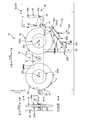
- FIG. 2 is a schematic front view of the material supply apparatus 10 that feeds out the preceding material 3ps from the preceding material coil 3p, and a diagram shown by arrows AA is a schematic side view of the preceding material coil 3p.
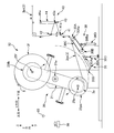
- FIG. 2 is a schematic front view of the material supply apparatus 10 to which the subsequent material coil 3f is attached, and a diagram shown by arrows BB is a schematic side view of the subsequent material coil 3f.
- It is the front schematic diagram of the material supply apparatus 10 which showed the state in which the turret rotation part 20 is turning.
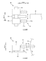
- FIG. 3 is a schematic top view of the correction device 50 shown by the arrow CC in FIG. 2B
- the lower diagram of FIG. 3 is a schematic front view of the correction device 50 shown by the arrow DD in FIG. It is.
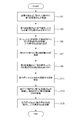
- FIG. 3 is a flowchart showing operation control of the material supply apparatus 10.
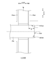
- FIG. 2B is a schematic cross-sectional view of the first positioning portion 25pa and the first pressing plate 25pb attached to the first rotating shaft 25p shown by the EE arrow in FIG. 2A.
- the second material supplied from the succeeding second material coil is joined to the first material, and the second material is fed.
- the absorbent material manufacturing method for manufacturing the absorbent article wherein the first material coil mounting step of mounting the first material coil around which the first material is wound to a first rotating shaft; The second material coil wound around the second material coil is attached to the second rotating shaft, and the first material fed out from the first material coil is driven by the rotation of the first rotating shaft.
- Each of the first material coil and the second material coil has a larger dimension in the outer diameter direction than a dimension in the width direction, and in the first material coil mounting step, a predetermined position in the axial direction of the first rotating shaft.
- a first deformation suppressing member for suppressing deformation in the width direction of the first material coil from both sides of the first material coil in the width direction.
- the second positioning portion provided at a predetermined position in the axial direction of the second rotating shaft and the deformation in the width direction of the second material coil are suppressed in the second material coil mounting step.
- a second deformation suppressing member for attaching the second material coil, the second material coil being sandwiched from both sides in the width direction.
- the first deformation suppressing member is a first pressing plate having a predetermined length in the outer diameter direction of the first rotating shaft, and the predetermined length of the first pressing plate. Is preferably smaller than the radial dimension of the first material coil before being fed out as the first material.
- the first deformation suppressing member is a first pressing plate having a predetermined length in the outer diameter direction of the first rotating shaft, and the predetermined length of the first pressing plate. However, it is desirable that it is larger than 1/3 times the radial dimension of the first material coil before being fed out as the first material.
- the second deformation suppressing member is a second pressing plate having a predetermined length in the outer diameter direction of the second rotating shaft, and the predetermined length of the second pressing plate. Is preferably smaller than the radial dimension of the second material coil before being fed out as the second material.
- the second deformation suppressing member is a second pressing plate having a predetermined length in the outer diameter direction of the second rotating shaft, and the predetermined length of the second pressing plate.
- the first positioning portion has a plate shape having a predetermined length in the outer diameter direction of the first rotating shaft, and the predetermined length of the first positioning portion is It is desirable that it is smaller than the radial dimension of the first material coil before being fed out as the first material.
- the second positioning portion has a plate shape having a predetermined length in the outer diameter direction of the second rotating shaft, and the predetermined length of the second positioning portion is It is desirable that it is smaller than the radial dimension of the second material coil before being fed out as the second material.
- the position where the first material is paid out in the axial direction of the first rotating shaft the position of the outer peripheral surface of the second material coil in the axial direction of the second rotating shaft, From the one side in the axial direction of the second rotary shaft to the other side while contacting the side surface of the outer peripheral portion of the second material coil attached to the second rotary shaft so that It is desirable to have a correction step of correcting the position of the outer peripheral surface in the axial direction of the second rotation axis by a correction device for correction.
- At least one of the correction devices is provided with respect to the second rotating shaft, and includes a moving unit for moving along the outer diameter direction of the second rotating shaft.
- the retracted position is located outside the outer peripheral surface of the second material coil to be attached so that the second material coil to be attached and the correction device do not contact each other.
- the straightening device is retracted, and in the straightening step, the straightening device moves from the retracted position to the inside in the outer diameter direction of the second rotating shaft so that the straightening device contacts the side surface of the outer peripheral portion of the second material coil. It is desirable to move the device.
- the contact portion of the correction device in contact with the second material coil is rotated by a rotating body that can rotate with the direction along the outer diameter direction of the second rotating shaft as the direction of the rotating shaft. It is desirable to be configured.
- the rotating body has a tapered shape in which the outer diameter of the rotating body increases from the inner side to the outer side in the outer diameter direction of the second rotating shaft.
- the straightening device in the straightening step, is a method of straightening the second material coil as a method of performing the straightening over the entire outer periphery of the second material coil.
- a method of rotating the second material coil around the second rotation axis in a state of being fixed at a predetermined position in the circumferential direction; and the correction device in the circumferential direction of the second material coil around the second rotation axis A method of moving the correction device along the circumferential direction of the second material coil in a state in which the second material coil is temporarily unable to rotate. It is desirable to use at least one of the methods.
- Such an absorbent article manufacturing method makes it possible to correct the entire circumference of the succeeding material coil.
- the method includes a detection step of detecting a position of an outer peripheral surface of the second material coil in the axial direction of the second rotation shaft by a detection unit, and in the correction step, the first step Based on information on the deviation between the position where the first material is fed out in the axial direction of the rotating shaft and the position of the outer peripheral surface of the second material coil in the axial direction of the second rotating shaft detected by the detecting step. Therefore, it is desirable to control the correction direction and correction amount of the correction device.
- the end portion of the second material located on the outer peripheral surface of the second material coil is set so that the end portion is not separated from the second material coil. It is desirable that the second material coil is fixed with a bonding material.
- the attachment robot attaches the first material coil to the first rotating shaft by contacting the first material coil, and the attachment Thereafter, the attachment robot attaches the first deformation suppressing member to the first rotating shaft, and attaches the first material coil to the first positioning portion and the first from both sides in the width direction of the first material coil.
- the attachment robot attaches the second material coil to the second positioning shaft by contacting the second material coil, and the attachment of the second material coil Later, the attachment robot attaches the second deformation suppressing member to the second rotation shaft, and the second material coil is applied from both sides in the width direction of the second material coil. It is desirable to interpose between the second deformation suppressing member and the second positioning portion.
- the second material supplied from the succeeding second material coil is joined to the first material, and the second material is fed.
- an absorbent article manufacturing apparatus for manufacturing an absorbent article, wherein a first rotating shaft for attaching the first material coil around which the first material is wound, and the second material are wound. The first material fed out from the first material coil is rotated by the driving rotation of the second rotating shaft by the second rotating shaft for mounting the second material coil and the driving rotation of the first rotating shaft.
- the second material coil has a joint portion that joins the second material to the first material by pressing toward the outer peripheral surface of the second material coil, and the first material coil and the second material coil are , Each width
- the dimension in the outer diameter direction is larger than the dimension in the direction, and a predetermined position in the axial direction of the first rotating shaft for mounting the first material coil sandwiching the first material coil from both sides in the width direction
- a first deformation suppressing member for suppressing deformation in the width direction of the first material coil, and from both sides in the width direction of the second material coil.
- a second positioning part provided at a predetermined position in the axial direction of the second rotating shaft for mounting with the second material coil interposed therebetween, and a second for suppressing deformation in the width direction of the second material coil.
- An apparatus for manufacturing an absorbent article comprising: a deformation suppressing member.
- the absorbent article manufacturing method according to the present embodiment is used for manufacturing absorbent articles in the material supply apparatus 10 of the absorbent article manufacturing apparatus 1. That is, the absorbent article manufacturing method (absorbent article manufacturing apparatus) according to the present embodiment is a method (apparatus) for manufacturing an absorbent article, and is a material supply method (material supply apparatus 10).
- FIG. 1 is a schematic view showing an example of a production line of the absorbent article production apparatus 1.
- FIG. 1 is a diagram in which some descriptions of the material supply device 10 and the processing unit 4 are omitted in order to explain the present invention in an easy-to-understand manner (hereinafter, the description of the omitted parts is also omitted).
- the horizontal direction of the paper surface is defined as the Y direction, and the left side (right side) of the paper surface is referred to as upstream (downstream).
- the absorbent article manufacturing apparatus 1 includes two material supply devices 10 (a material supply first device 10a and a material supply second device 10b) and two processing units 4 (an absorber processing unit 4a and an end cutter 4b). Yes. And the carrying-in of the material 3 to the material supply 1st apparatus 10a and the material supply 2nd apparatus 10b is made with the form of the material coil by which the continuous sheet-like material 3 was wound by the coil shape. That is, in the material supply 1st apparatus 10a and the material supply 2nd apparatus 10b, the continuous sheet-like material 3 is drawn out from the form of the material coil. In addition, the material supply 1st apparatus 10a and the material supply 2nd apparatus 10b are each provided corresponding to the kind of the material 3. FIG.
- a conveyance mechanism conveys the material 3a fed from the material supply first apparatus 10a to the downstream side in the Y direction, and absorber processing on the conveyance path
- the absorber 2 is attached (transferred) onto the material 3a.
- the material 3a in this state is further conveyed downstream in the Y direction, and the material 3b fed from the material supply second device 10b sandwiches the absorber 2, so that various thread rubbers can be attached and joined.
- a conveyance mechanism conveys until it reaches the installation position of the end cutter 4b on a conveyance path
- absorbent article examples include sanitary napkins, unfolded and pants-type disposable diapers, etc., but any article that absorbs the excretion fluid of the wearer may be used.
- an absorbent article is comprised by the absorbent body 2 comprised by the superabsorbent polymer (SAP) etc. which absorb excretion fluid, the liquid-permeable nonwoven fabric etc. which were distribute
- Such a configuration varies depending on the application as exemplified in the absorbent article, and the processing unit 4 and the material supply apparatus 10 provided in the absorbent article manufacturing apparatus 1 are appropriately changed according to the application.
- the material 3 according to the present embodiment has a continuous sheet shape, and is fed out from the form of a material coil around which the continuous sheet-shaped material 3 is wound.
- the material coil is formed by affixing the winding start end portion of the material 3 to the paper tube and spirally winding the material coil, and cuts the continuous sheet-shaped material 3 when reaching a predetermined outer diameter (depending on the type of the material 3). Is formed.
- the terminal part is fixed to the material coil by the bonding material 5 (see FIGS. 2B to 2D). .
- the material 3 is transported from the manufacturing location of the material 3 to the absorbent article manufacturing apparatus 1 in the form of a material coil having a predetermined outer diameter, and is transported into the material supply apparatus 10 after the transport.
- the form of the material coil of the material 3 according to the present embodiment is such that the dimension in the outer diameter direction is larger than the dimension in the width direction of the material coil.
- the dimension is about 10 to 20 times larger than the dimension in the width direction. That is, the dimension in the outer diameter direction is sufficiently larger than the dimension in the width direction of the material coil.
- the material 3 which concerns on this Embodiment is a continuous sheet form comprised with highly flexible nonwoven fabrics, such as an airlaid pulp nonwoven fabric, a spunlace nonwoven fabric, and an air through nonwoven fabric.
- the material coil is made of a highly flexible nonwoven fabric, and the dimension in the outer diameter direction is sufficiently larger than the dimension in the width direction. Therefore, the material coil is easily deformed in the width direction of the material coil due to vibration during transportation of the material coil or due to the weight of the material 3 when the width direction is directed in the vertical direction when the material coil is moved.
- the material supply apparatus 10 will be described with reference to FIGS. 2A and 2B.
- the material supply first device 10a and the material supply second device 10b are provided according to the type of the material 3, but in the present embodiment, the material supply first device 10a and the material supply second device.
- the basic configurations of 10b are the same. Therefore, below, one material supply apparatus 10 is demonstrated.
- FIG. 2A is a schematic front view of the material supply apparatus 10 that feeds out the preceding material 3ps (corresponding to the first material) from the preceding material coil 3p (corresponding to the first material coil), and is a view shown by arrows AA. These are the schematic side views of the preceding material coil 3p.
- the preceding material coil 3p is shown as an outer diameter before the preceding material 3ps is fed out.
- FIG. 2B is a schematic front view of the material supply apparatus 10 to which the succeeding material coil 3f (corresponding to the second material coil) is attached, and the view shown by arrows BB is a schematic side view of the succeeding material coil 3f.
- FIG. 2A is a schematic front view of the material supply apparatus 10 that feeds out the preceding material 3ps (corresponding to the first material) from the preceding material coil 3p (corresponding to the first material coil), and is a view shown by arrows AA.
- FIG. 2A is a schematic front view of the material supply apparatus 10 that feeds
- the X direction and the Y direction are each directed in the horizontal direction
- the Z direction is directed in the vertical direction.
- the left side (right side) of the paper surface is upstream (downstream) with the horizontal direction of the paper surface as the Y direction
- the back side (front side) of the paper surface is up (down) with the vertical direction of the paper surface as the Z direction.
- the horizontal direction of the paper surface is the X direction
- the left side (right side) of the paper surface is called the back (front).
- the positions of the first rotating shaft 25p and the second rotating shaft 25f are represented by a joint portion P1 and a mounting portion P2, as shown in FIGS. 2A and 2B.
- the first rotation shaft 25p is located at the joint P1
- the second rotation shaft 25f is located at the attachment portion P2.
- the attachment is performed.
- the first rotation shaft 25p is positioned at the part P2.
- the material supply device 10 includes a first rotation shaft 25p located at the joint P1, a second rotation shaft 25f located at the attachment portion P2, a first rotation shaft 25p, and a second rotation shaft.
- the turret rotation unit 20 for switching the position of the rotary shaft 25f, the joint 30 for joining the succeeding material 3fs (corresponding to the second material) to the preceding material 3ps, and the preceding material after joining the succeeding material 3fs to the preceding material 3ps.
- the first rotating shaft 25p located at the joint P1 includes a motor (not shown) that is a power source for driving and rotating in the direction along the X direction as a rotating shaft, and a predetermined position of the first rotating shaft 25p in the X direction.
- a motor not shown
- a predetermined position of the first rotating shaft 25p in the X direction are provided with a first positioning portion 25pa having a substantially circular plate shape.
- the preceding material coil 3p is attached to the front side in the X direction of the first positioning portion 25pa, and further, a substantially circular shape is formed on the near side in the X direction of the preceding material coil 3p.
- a first pressing plate 25pb (corresponding to a first deformation suppressing member) is attached.
- the first positioning portion 25pa and the first pressing plate 25pb according to the present embodiment are smaller than the outer diameter size of the preceding material coil 3p before the outer diameter size of the first positioning portion 25pa and the first pressing plate 25pb are extended.
- the diameter is larger than 1/3 of the outer diameter of the preceding material coil 3p before being fed out.
- the first deformation suppressing member is the first pressing plate 25pb having a predetermined length in the outer diameter direction of the first rotating shaft 25p
- the predetermined length of the first pressing plate 25pb is the first material (preceding). It is smaller than the radial dimension of the first material coil (preceding material coil 3p) before being fed out as the material 3ps), and more than 1/3 times the radial dimension.
- the first positioning portion 25pa has a plate shape having a predetermined length in the outer diameter direction of the first rotating shaft 25p, and the predetermined length of the first positioning portion 25pa is the first material (preceding material 3ps). Is smaller than the radial dimension of the first material coil (preceding material coil 3p) before being fed out.
- the preceding material coil 3p rotates counterclockwise, and the preceding material 3ps is fed out from the lower side in the Z direction of the preceding material coil 3p to the downstream side in the Y direction. It is.
- the advanced material 3ps thus fed is supplied from the material supply device 10 to the transport mechanism via the storage device 40.
- the second rotating shaft 25f located in the attachment portion P2 includes a motor (not shown) that is a power source for driving and rotating about the direction along the X direction as a rotating shaft, and a substantially circular plate at a predetermined position in the X direction.
- a second positioning portion 25fa having a shape is provided. As shown in the direction of arrow BB, the trailing material coil 3f is attached to the front side in the X direction of the second positioning portion 25fa, and further, the second material coil 3f is positioned on the near side in the X direction.
- a two pressing plate 25fb (corresponding to a second deformation suppressing member) is attached.
- the second positioning portion 25fa and the second pressing plate 25fb according to the present embodiment are smaller than the outer diameter size of the trailing material coil 3f before the outer diameter size of the second positioning plate 25fa and the second pressing plate 25fb are extended.
- the outer diameter dimension is larger than 1/3 of the outer diameter dimension of the succeeding material coil 3f before being fed out. That is, the second deformation suppressing member is the second pressing plate 25fb having a predetermined length in the outer diameter direction of the second rotating shaft 25f, and the predetermined length of the second pressing plate 25fb is the second material (rear). It is smaller than the radial dimension of the second material coil (following material coil 3f) before being fed out as the row material 3fs), and further larger than 1/3 times the radius dimension.
- the second positioning portion 25fa has a plate shape having a predetermined length in the outer diameter direction of the second rotating shaft 25f, and the predetermined length of the second positioning portion 25fa is equal to the second material (following material 3fs). ) Is smaller than the radial dimension of the second material coil (following material coil 3f) before being fed out.
- the turret rotating unit 20 is provided with a turret 21 on a belt plate.
- the turret 21 includes a motor (not shown) that is a power source for driving and rotating with a direction along the X direction as a rotation axis. It is supported by the shaft 21a.
- the first rotation shaft 25p and the second rotation shaft 25f are provided at positions where the turret shaft 21a is point-symmetric. Therefore, when the turret 21 turns around the turret shaft 21a, the positions of the first rotating shaft 25p and the second rotating shaft 25f (that is, the positions of the joint portion P1 and the attachment portion P2) can be switched. .
- the joint portion 30 is provided on the lower side in the Z direction of the preceding material 3ps fed out at the joining portion P1, and is a device for joining the succeeding material 3fs to the preceding material 3ps.
- the joint portion 30 includes a first rotating roller 30A that rotates about the first fixed shaft 30Aa along the X direction, a swing arm that swings about the first fixed shaft 30Aa, and a first fixed shaft of the swing arm.
- a second rotating roller 30B that rotates around a second fixed shaft 30Ba provided at the end opposite to 30Aa, and a rotatable endless belt that is stretched between the first rotating roller 30A and the second rotating roller 30B.
- the preceding material 3ps is pressed against the succeeding material coil 3f to join the succeeding material 3fs to the preceding material 3ps (specifically, the operation of the material supply device 10).
- the belt member 30C (including the first rotating roller 30A and the second rotating roller 30B that rotatably supports the belt member 30C) that contacts the preceding material 3ps at the time of joining is included in order to surely perform the joining.
- In the X direction is larger than the size of the preceding material 3 ps in the X direction as shown by arrows AA.
- the width of the belt member 30C is larger than the width of the preceding material 3ps, and the belt member 30C comes into contact with the entire width direction of the preceding material 3ps, so that the succeeding material coil 3f (same as the preceding material 3ps).
- the following material 3fs is joined to the preceding material 3ps by pressing the entire width direction).
- the cutting part 35 is provided on the lower side in the Z direction of the first material 3ps fed out in the joining part P1 and on the upstream side in the Y direction of the joint part 30, and joins the succeeding material 3fs to the preceding material 3ps.
- This is a device for cutting the preceding material 3 ps.
- the cutting portion 35 swings the arm member 35A supported so as to be swingable around the rotation shaft 35Aa along the X direction, the cutter blade 35B fixed to the swing end of the arm member 35A, and the arm member 35A.
- a cutting section actuator 35C such as an air cylinder to be moved.
- the accumulation device 40 is a so-called dancer unit that accumulates the material 3 to be fed out in a loop form so as to be supplied to the transport mechanism of the absorbent article manufacturing apparatus 1. And the tension
- the storage device 40 is located at the inlet of the storage device 40 and is rotatably supported around a rotation axis 41a along the X direction.
- the storage device 40 is positioned at the outlet of the storage device 40 and extends along the X direction.
- the outlet roll 42 supported rotatably around the rotation shaft 42a, and guided in a reciprocating manner in a predetermined direction (Y direction in FIGS.
- the correction device 50 is a device that corrects the position of the outer peripheral surface in the X direction of the subsequent material coil 3f attached to the attachment portion P2. And at least 1 is provided with respect to the attachment part P2, and it is provided so that it can be located in the outer side of an outer diameter direction rather than the outer diameter of the succeeding material coil 3f before extending
- the upper diagram of FIG. 3 is a schematic top view of the correction device 50 shown by the arrow CC in FIG. 2B
- the lower diagram of FIG. 3 is a schematic front view of the correction device 50 shown by the arrow DD in FIG. It is. Note that in both the schematic top view and the schematic front view, members may be omitted as appropriate in order to easily understand the present invention.
- the correction device 50 supports the contact portion 51 that contacts the outer peripheral portion of the succeeding material coil 3 f and the contact portion 51 so as to be rotatable around the rotation axis along the Y direction.
- a second moving unit 54 that is reciprocated by a motor is provided.
- the correction device 50 includes at least one second rotation shaft 25f and a moving unit (first moving unit 53) for moving along the outer diameter direction of the second rotation shaft 25f. .
- the contact portion 51 includes a rotator 51a and a rotator support portion 51b, and the rotator support portion 51b supports the contact portion so that the rotator 51a can rotate about the direction along the Y direction as a rotation axis. Supported by the portion 52.
- the rotating body 51a has a tapered shape in which the outer diameter increases from the inner side to the outer side in the outer diameter direction of the second rotating shaft 25f (from the front end to the end of the rotating body 51a). That is, the contact portion (contact portion 51) of the correction device 50 that is in contact with the second material coil (following material coil 3f) has a direction along the outer diameter direction of the second rotation shaft 25f as the rotation axis (rotary body support portion 51b). ), And the rotating body 51a has a tapered shape in which the outer diameter of the rotating body 51a increases from the inside to the outside in the outer diameter direction of the second rotating shaft 25f. .
- the detection unit 60 is a sensor that detects the position of the outer peripheral surface of the succeeding material coil 3f in the X direction before being fed out. And as shown in FIG. 2B, it is provided in the position of about 10:00 of the attaching part P2 in the back
- FIG. 2C is a schematic front view of the material supply apparatus 10 showing a state in which the turret rotation unit 20 is turning.
- FIG. 2D is a schematic front view of the material supply apparatus 10 showing a state in which the preceding material 3ps is joined to the succeeding material 3fs.
- FIG. 4 is a diagram illustrating a relationship between the control unit 100 and other devices.
- FIG. 5 is a flowchart showing the operation control of the material supply apparatus 10.
- FIG. 6 is a schematic cross-sectional view of the first positioning portion 25pa and the first pressing plate 25pb attached to the first rotation shaft 25p as shown by the arrows EE in FIG. 2A.
- the preceding material coil 3p is attached to the first rotating shaft 25p.
- the attachment is performed by the attachment robot 70.
- the attachment robot 70 according to the present embodiment is a so-called articulated robot, and includes an arm having a plurality of joints, and an insertion portion and a gripping portion at the tip of the arm.
- the insertion portion is inserted into the paper tube of the material coil (the preceding material coil 3p and the succeeding material coil 3f), and is provided to fix the material coil from the inside of the paper tube.
- the gripping portion is provided for gripping and fixing the pressing plates (first pressing plate 25pb and second pressing plate 25fb).
- the attachment robot 70 can move each of the fixed robots by rotating the arm or the like.
- the attachment robot 70 is located upstream of the attachment portion P2 in the Y direction, and can attach a material coil to a rotation shaft (second rotation shaft 25f in FIG. 2A) located at the attachment portion P2. That is, the arm can be extended). Therefore, as shown in FIG. 2A, when the first rotation shaft 25p is located at the joint P1, the control unit 100 turns the turret 21 to move the first rotation shaft 25p to the attachment portion P2 ( Step S1).
- the control unit 100 issues a command to the mounting robot 70, and the mounting robot 70 sets a new material coil in a material storage area (not shown) as the preceding material coil 3p (that is, the control unit 100 precedes the new material coil). Recognize as material coil 3p) and take it out from the material storage. Then, the preceding material coil 3p is moved to the attachment portion P2, and the preceding material coil 3p is attached to the first rotating shaft 25p (when the material coil is attached at the attachment portion P2, the correction device 50 is positioned at a retracted position described later. If not, the control unit 100 moves the correction device 50 to the retracted position before attachment (details will be described later). That is, the first material coil (preceding material coil 3p) around which the first material (preceding material 3ps) is wound is attached to the first rotating shaft 25p (corresponding to the first material coil attaching step).
- the attachment of the preceding material coil 3p by the attaching robot 70 is performed by aligning the coil center of the preceding material coil 3p from the near side in the X direction so as to follow the rotation axis of the first rotating shaft 25p, This is done by pushing the preceding material coil 3p from the near side in the X direction to the far side.
- the side surface on the back side of the preceding material coil 3p specifically, the paper tube of the preceding material coil 3p that is difficult to deform
- the attachment robot 70 grasps the first pressing plate 25pb by the grasping portion and attaches it to the first rotating shaft 25p.
- the first presser plate 25pb has a first presser plate hole H25pb that is a hole into which the first rotating shaft 25p is inserted, and is formed on the bottom surface of the first presser plate hole H25pb.
- the first pressing plate bottom surface B25pb further has a hole smaller than the outer diameter of the first rotating shaft 25p. Accordingly, in the mounting robot 70, the first pressing shaft bottom surface B25pb is the end surface on the near side of the first rotating shaft 25p in a state where the first rotating shaft 25p is inserted into the first pressing plate hole H25pb.
- the first pressing plate 25pb is attached to the first rotating shaft 25p by pushing from the near side in the X direction to the far side until it comes into contact with the end face 25pt (step S3).
- the first positioning portion 25pa provided at a predetermined position in the axial direction of the first rotating shaft 25p and the deformation in the width direction of the first material coil (preceding material coil 3p) are suppressed.
- the first material coil (preceding material coil 3p) is sandwiched and attached from both sides in the width direction of the first material coil (preceding material coil 3p) with the first deformation suppressing member (first pressing plate 25pb).
- the attachment robot 70 attaches the first material coil (preceding material coil 3p) to the first positioning shaft 25p in contact with the first positioning portion 25pa, and after the attachment, The attachment robot 70 attaches the first deformation suppressing member (first pressing plate 25pb) to the first rotating shaft 25p, and the first material coil (preceding material) from both sides in the width direction of the first material coil (preceding material coil 3p).
- the coil 3p) is sandwiched between the first positioning portion 25pa and the first deformation suppressing member (first pressing plate 25pb).
- the depth D of the hole portion of the first pressing plate 25pb is such that the first pressing plate 25pb does not come into contact with the front side surface of the preceding material coil 3p. That is, the preceding material coil 3p and the first pressing plate 25pb are attached with a gap in the X direction. By doing so, the preceding material coil 3p is fed out, and the preceding material that is fed out when the outer diameter size of the preceding material coil 3p becomes smaller than the outer diameter size of the first positioning portion 25pa and the first pressing plate 25pb. 3 ps can be prevented from excessively contacting the first positioning portion 25pa and the first pressing plate 25pb.
- the turret rotation unit 20 turns the turret 21 to move the first rotation shaft 25p located at the attachment portion P2. Move to the joint P1. Then, the preceding material 3ps is fed out from the preceding material coil 3p attached to the first rotating shaft 25p moved to the joint portion P1, and the material 3 is supplied to the transport mechanism of the absorbent article manufacturing apparatus 1 (step S5, FIG. 2A). ). Then, due to the turning of the turret 21, the second rotation shaft 25f located at the joint portion P1 is located at the attachment portion P2 (step S7).
- the succeeding material coil 3f is attached to the second rotating shaft 25f. That is, the second material coil (following material coil 3f) wound with the second material (following material 3fs) is attached to the second rotating shaft 25f (corresponding to the second material coil attaching step).
- the attachment is performed in the same manner as the attachment of the preceding material coil 3p and the first pressing plate 25pb to the first rotating shaft 25p described above. That is, the attachment robot 70 takes the new material coil as the subsequent material coil 3f (that is, the control unit 100 recognizes the new material coil as the subsequent material coil 3f) and removes it from the material storage, and the subsequent material coil 3f. Is attached so as to contact the second positioning portion 25fa of the second rotating shaft 25f.
- the mounting robot 70 grips the second pressing plate 25fb with the gripping portion, and mounts the bottom surface of the hole of the second pressing plate 25fb and the end surface of the second rotating shaft 25f in contact with each other ( Step S9, the state shown in FIG.
- the second positioning portion 25fa provided at a predetermined position in the axial direction of the second rotating shaft 25f and the deformation in the width direction of the second material coil (following material coil 3f) are deformed.
- the second deformation suppressing member second pressing plate 25fb
- the attachment robot 70 attaches the second material coil (following material coil 3f) to the second positioning shaft 25f by contacting the second material coil (following material coil 3f).
- the attachment robot 70 attaches the second deformation suppressing member (second pressing plate 25fb) to the second rotating shaft 25f, and the second material coil (from the both sides in the width direction of the second material coil (following material coil 3f)) The succeeding material coil 3f) is sandwiched between the second positioning portion 25fa and the second deformation suppressing member (second pressing plate 25fb).
- the second material positioning portion 25fa and the second presser plate 25fb are attached so that the subsequent material coil 3f is sandwiched from both sides in the width direction, thereby the width direction of the subsequent material coil 3f.
- the outer diameter of the second positioning portion 25fa and the second pressing plate 25fb is smaller than the outer diameter of the trailing material coil 3f before being fed out. Therefore, when the outer peripheral portion of the succeeding material coil 3f is greatly displaced in the width direction, the deformation is sufficiently suppressed only by mounting the succeeding material coil between the second positioning portion 25fa and the second pressing plate 25fb. (Correction) may not be possible.
- the position of the outer peripheral surface of the succeeding material coil 3f in the X direction is set to the position of the preceding material 3ps by the correcting device 50. Correction (adjustment) to be the same as (corresponds to the correction process).
- the correction by the correction device 50 is performed based on the detection result of the detection unit 60. That is, the control unit 100 drives and rotates the second rotation shaft 25f to rotate the subsequent material coil 3f counterclockwise, and the detection unit 60 rotates the outer material surface of the subsequent material coil 3f in the X direction. The position is continuously detected, and the detection result is immediately transmitted to the control unit 100 (corresponding to a detection step). Then, the control unit 100 recognizes the received detection result as the position of the outer peripheral surface of the succeeding material coil 3f in the X direction, and the calculation unit 102 calculates the amount of deviation from the position of the preceding material 3ps in the X direction. .
- Information on the position of the preceding material 3ps in the X direction may be stored in advance in the storage unit 101 as a predetermined position sandwiched between the first positioning portion 25pa and the first pressing plate 25pb, or the preceding material 3ps may be obtained by a sensor or the like. May be directly detected and the detection result may be used.
- the control part 100 will move the correction apparatus 50 (contact part support part 52) located in the outer position (henceforth a retracting position) of the outer diameter direction from the outer peripheral surface of the succeeding material coil 3f.
- the movement is performed based on the shift amount, and the control unit 100 moves the contact portion support unit 52 in the X direction by the second moving unit 54 at the retracted position. That is, if the shift amount is a shift to the back side (front side) in the X direction, the control unit 100 is the back side (front side) in the X direction and is positioned at a position corresponding to the shift amount.
- the contact portion support portion 52 is moved to a position where the side surface of the outer peripheral portion of the row material coil 3f can come into contact with the outer peripheral surface of the rotating body 51a. And the control part 100 moves the contact part support part 52 to the downstream of a Y direction by the 1st moving part 53 to the position where the rotary body 51a contacts the side surface of the outer peripheral surface of the subsequent material coil 3f. The contact portion support 52 moves to the position in the X direction where the rotating body 51a and the succeeding material coil 3f can contact, and then moves downstream in the Y direction. First, the rotating body 51a and the following material coil 3f are moved.
- the contact portion support portion 52 moves in the X direction so that the rotating body 51a and the succeeding material coil 3f come into contact with each other after the contact portion support portion 52 moves to a position in the X direction where no contact is made and moves downstream in the Y direction. May move).
- the control unit 100 detects the outer peripheral surface of the subsequent material coil 3f in the X direction continuously transmitted from the detection unit 60. Based on the position information, the calculation unit 102 sequentially calculates the shift amount, and moves the contact portion support unit 52 (the rotator 51a) so that the shift amount becomes zero. That is, the position of the contact portion support portion 52 (rotating body 51a) is adjusted so that the amount of deviation becomes zero. The position can be adjusted by moving the second moving portion 54 in the X direction. As described above, since the rotating body 51a has a tapered shape, the first moving portion 53 can adjust the position in the Y direction. It is also possible to move to.
- the contact part support part 52 is once retracted position Then, the contact portion support portion 52 is moved to the opposite side in the X direction of the succeeding material coil 3f, and correction is performed so that the above-described deviation amount becomes zero.
- the detection process which detects the position of the outer peripheral surface of the 2nd material coil (following material coil 3f) in the axial direction of the 2nd rotating shaft 25f by the detection part 60, and in a correction process, it is the 1st rotating shaft 25p.
- the control part 100 will move the contact part support part 52 to a retracted position, and will stop rotation of the subsequent material coil 3f (step S11).
- the movement of the contact portion support portion 52 to the retracted position is to prevent contact with the subsequent material coil 3f when the subsequent material coil 3f is attached next time. That is, in the second material coil attaching step, the second material coil to be attached (following material coil 3f) and the correction device 50 are prevented from contacting the outer peripheral surface of the second material coil to be attached (following material coil 3f).
- the correction device 50 is retracted to a retraction position located outside in the outer diameter direction, and in the correction process, the retraction position is such that the correction device 50 contacts the side surface of the outer peripheral portion of the second material coil (following material coil 3f).
- the correction device 50 is moved to the inside in the outer diameter direction of the second rotation shaft 25f.
- This “predetermined dimension for movement” is stored in the storage unit 101 in advance.
- the “information about the outer diameter of the preceding material coil 3p that is reduced by feeding” integrates the amount of the preceding material 3ps that has been fed by the calculation unit 102 based on the number of rotations of the first rotating shaft 25p and the rotation time. May be calculated from the remaining amount of the preceding material 3ps of the preceding material coil 3p, or a sensor or the like is provided to directly detect the outer diameter direction position of the outer peripheral surface of the preceding material coil 3p. Results may be used.
- the preceding material 3ps is further fed out from the preceding material coil 3p, and when the outer diameter dimension of the preceding material coil 3p becomes smaller than the “predetermined dimension for joining”, the control unit 100
- the succeeding material coil 3f located at the joint P1 is rotated counterclockwise. This “predetermined dimension for joining” is stored in the storage unit 101 in advance. Then, “information on the outer diameter dimension of the preceding material coil 3p that is reduced by feeding” is obtained by calculation or the like in the same manner as described above.
- the winding end portion of the subsequent material 3fs located on the outer peripheral surface of the subsequent material coil 3f is fixed to the subsequent material coil 3f by the bonding material 5.
- the winding end portion is fixed to the succeeding material coil 3 f by the joining material 5. That is, at the winding end portion of the second material (following material 3fs) located on the outer peripheral surface of the second material coil (following material coil 3f), the end portion is separated from the second material coil (following material coil 3f).
- the terminal portion is fixed to the second material coil (following material coil 3 f) by the bonding material 5 so as not to leave.
- the fixing of the winding end portion and the succeeding material coil 3f is released when the succeeding material 3fs is joined to the preceding material 3ps and the succeeding material 3fs is fed out from the succeeding material coil 3f ( The bonding material 5 is peeled off).
- the rotational speed of the second rotating shaft 25f is adjusted so that the rotational peripheral speed on the outer peripheral surface of the succeeding material coil 3f matches the feeding speed of the preceding material 3ps.
- the joint actuator 30D moves the swing arm in the Z direction.
- the belt member 30C is swung upward to contact the preceding material 3ps and pressed against the outer peripheral surface of the rotating succeeding material coil 3f as it is to join the succeeding material 3fs to the preceding material 3ps (this embodiment).
- the preceding material 3ps and the succeeding material 3fs are joined by the joining material provided outside the winding end portion of the succeeding material coil 3f). That is, the second material rotating the first material (preceding material 3ps) fed from the first material coil (preceding material coil 3p) by the driving rotation of the first rotating shaft 25p is rotated by the driving rotation of the second rotating shaft 25f.
- the second material (following material 3fs) is joined to the first material (preceding material 3ps) by pressing toward the outer peripheral surface of the material coil (following material coil 3f) (corresponding to the joining step).
- the cutting part actuator 35C swings the arm member 35A upward in the Z direction and cuts the preceding material 3ps by the cutter blade 35B (step) S15). That is, the preceding material 3ps supplied from the material supply device 10 to the transport mechanism is changed to the succeeding material 3fs fed from the succeeding material coil 3f without stopping the feeding of the preceding material 3ps. That is, without stopping the feeding of the first material (preceding material 3ps) continuously fed from the preceding first material coil (preceding material coil 3p), the succeeding second material coil (following material coil 3f). The second material (following material 3fs) supplied from is joined to the first material (previous material 3ps) to feed out the second material (following material 3fs).
- the control unit 100 precedes the succeeding material 3fs (following material coil 3f) fed out on the second rotating shaft 25f. Recognizing the material as 3 ps (preceding material coil 3 p), it is overwritten and stored in the storage unit 101. Therefore, if it is necessary to attach the subsequent material coil 3f further (necessary to join the subsequent material 3fs to the preceding material 3ps), the new material coil is moved to the first rotating shaft 25p located at the attachment portion P2. It is attached as a material coil 3f.
- the correction, bonding, and the like performed on the subsequent material coil 3f attached to the second rotating shaft 25f described above are similarly performed on the subsequent material coil 3f attached to the first rotating shaft 25p.
- the new material coil is alternately and repeatedly attached to the first rotating shaft 25p or the second rotating shaft 25f positioned at the attachment portion P2 as the subsequent material coil 3f, and the subsequent material coil 3f is subjected to correction or By performing the joining or the like, it is possible to continuously join the succeeding material 3fs to the preceding material 3ps and feed the succeeding material 3fs to the transport mechanism without stopping the feeding of the preceding material 3ps.
- the succeeding material coil 3f rotating the preceding material 3ps fed from the preceding material coil 3p by the driving rotation of the second rotating shaft 25f.
- the dimension in the direction is larger, and in the first material coil mounting step, the first positioning portion 25pa provided at a predetermined position in the axial direction of the first rotating shaft 25p and the deformation in the width direction of the preceding material coil 3p are suppressed.
- the first presser plate 25pb for mounting is attached with the preceding material coil 3p sandwiched from both sides in the width direction of the preceding material coil 3p, and in the second material coil attaching step, a predetermined position in the axial direction of the second rotating shaft 25f Of the subsequent material coil 3f and the second pressing plate 25fb for suppressing deformation in the width direction of the subsequent material coil 3f. It was attaching across the succeeding material coil 3f from both sides directions. For this reason, it is possible to suppress a shift in joining the preceding material 3ps and the succeeding material 3fs.
- the succeeding material 3ps supplied from the succeeding material coil 3f is joined to the preceding material 3ps without stopping the feeding of the preceding material 3ps continuously fed from the preceding material coil 3p.
- the phenomenon in which the preceding material 3ps and the succeeding material 3fs shift in the width direction at the time of feeding out is not considered at all. Therefore, as in the case of the material coil of the material 3 according to the present embodiment, in the case where it is configured only by a highly flexible material and the dimension in the outer diameter direction is sufficiently larger than the dimension in the width direction, the width There has been a frequent problem that the preceding material 3ps and the succeeding material 3fs are joined in a state shifted in the direction.
- the first positioning portion 25pa (second positioning) provided at a predetermined position in the axial direction of the first rotating shaft 25p (second rotating shaft 25f).
- the preceding material coil 3p (following material coil 3f) is sandwiched from both sides in the width direction of 3f).
- the first deformation suppressing member is a first pressing plate having a predetermined length in the outer diameter direction of the first rotating shaft 25p (second rotating shaft 25f).
- 25pb second presser plate 25fb
- the predetermined length of the first presser plate 25pb is the preceding material coil 3p (rear) before being fed out as the preceding material 3ps (following material 3fs) It was decided to be smaller than the radial dimension of the row material coil 3f).
- the first positioning portion 25pa (second positioning portion 25fa) has a plate shape having a predetermined length in the outer diameter direction of the first rotating shaft 25p (second rotating shaft 25f), and the first positioning portion 25pa ( The predetermined length of the second positioning portion 25fa) is smaller than the radial dimension of the preceding material coil 3p (following material coil 3f) before being fed as the preceding material 3ps (following material 3fs).
- the width of the belt member 30C is larger than the width of the preceding material 3ps and the following material coil 3f. .
- the preceding material coil 3p before the first presser plate 25pb (second presser plate 25fb) and the first positioning portion 25pa (second positioning portion 25fa) are fed out as the preceding material 3ps (following material 3fs).
- the belt member 30C swings upward in the Z direction to press the preceding material 3ps against the following material coil 3f, and the preceding material 3ps and the following material 3fs are When joining, it becomes possible to suppress that the belt member 30C contacts the first pressing plate 25pb (second pressing plate 25fb) and the first positioning portion 25pa (second positioning portion 25fa).
- the first deformation suppressing member is a first pressing plate having a predetermined length in the outer diameter direction of the first rotating shaft 25p (second rotating shaft 25f).
- 25pb second presser plate 25fb
- the predetermined length of the first presser plate 25pb is the preceding material coil 3p (rear) before being fed out as the preceding material 3ps (following material 3fs) It was decided that it was larger than 1/3 times the radial dimension of the row material coil 3f).
- the first pressing plate 25pb (second holding plate) effective for suppressing the deformation in the width direction of the preceding material coil 3p (following material coil 3f).
- the radial dimension of the plate 25fb is different, the preceding material coil 3p (following material coil 3f) before the radial size of the first pressing plate 25pb (second pressing plate 25fb) is fed out as the preceding material 3ps (following material 3fs).
- the correcting device 50 when the position of the outer peripheral surface of the succeeding material coil 3f is corrected by the correcting device 50, if the radius is smaller than 1/3 times as described above, the first rotating shaft 25p (the second rotating shaft 25f). ) May rotate so that the outer peripheral portion of the succeeding material coil 3f meanders in the width direction. In such a case, it is difficult to perform correction by the correction device 50. Therefore, by making the radial dimension of the first pressing plate 25pb (second pressing plate 25fb) larger than 1/3 times, it is possible to further suppress the shift in the width direction of the material coil.
- the position where the preceding material 3ps is fed out in the axial direction of the first rotating shaft 25p is the same as the position of the outer peripheral surface of the succeeding material coil 3f in the axial direction of the second rotating shaft 25f.
- the apparatus 50 includes a correction step of correcting the position of the outer peripheral surface in the axial direction of the second rotation shaft 25f.
- At least one correction device 50 is provided for the second rotating shaft 25f, and the first moving unit 53 for moving along the outer diameter direction of the second rotating shaft 25f is provided.
- the retracted position is located outside the outer peripheral surface of the attached succeeding material coil 3f in the outer diameter direction so that the attached succeeding material coil 3f and the correction device 50 do not come into contact with each other.
- the straightening device 50 is retracted, and in the straightening process, the straightening device 50 is moved from the retracted position to the inner side in the outer diameter direction of the second rotation shaft 25f so that the straightening device 50 contacts the side surface of the outer peripheral portion of the subsequent material coil 3f. It was decided to move.
- the correction device 50 can be moved in the outer diameter direction of the second rotation shaft 25f, and when the subsequent material coil 3f is attached, it is retracted to the outside in the outer diameter direction so as not to contact the subsequent material coil 3f.
- the position of the outer peripheral surface of the succeeding material coil 3f is corrected, it is moved inward in the outer diameter direction so as to come into contact with the outer peripheral portion of the succeeding material coil 3f. Therefore, it is possible to suppress the subsequent material coil 3 f from coming into contact with the correction device 50 when the subsequent material coil 3 f is attached.
- connects the subsequent material coil 3f is the rotary body 51a which can rotate by making the direction along the outer-diameter direction of the 2nd rotating shaft 25f into the direction of a rotating shaft. It was decided that it was comprised. That is, it is possible to reduce the frictional force generated between the contact portion 51 and the succeeding material coil 3f as compared with the case where the contact portion 51 cannot rotate.
- the rotating body 51a has a tapered shape in which the outer diameter of the rotating body 51a increases from the inner side to the outer side in the outer diameter direction of the second rotating shaft 25f. That is, the amount of correction is different between the inner side and the outer side of the outer diameter direction of the rotating body 51a, and the correction can be made larger as it goes from the inner side to the outer side in the outer peripheral direction of the subsequent material coil 3f.
- the larger the correction can be made from the inner side toward the outer side in the outer peripheral direction of the succeeding material coil 3f the more effectively the side closer to the outer peripheral surface (outer side in the outer diameter direction) in the outer peripheral portion of the subsequent material coil 3f. It becomes possible to do.
- this Embodiment has the detection process which detects the position of the outer peripheral surface of the succeeding material coil 3f in the axial direction of the 2nd rotating shaft 25f by the detection part 60, and a 1st rotating shaft is in a correction process. Correction based on information on the deviation between the position at which the preceding material 3ps is fed out in the axial direction of 25p and the position of the outer peripheral surface of the succeeding material coil 3f in the axial direction of the second rotating shaft 25f detected by the detection step The correction direction and correction amount of the device 50 were controlled.
- the calculation unit 102 can calculate the deviation amount from the detection result continuously detected from the detection unit 60 and the information on the position where the preceding material 3 ps is fed out, and the control unit 100 calculates the deviation amount. It is possible to adjust (control) the correction direction and correction amount of the correction device 50. That is, such adjustment can be performed promptly and accurately as compared with the case of manual operation, and the shift in joining the preceding material 3ps and the succeeding material 3fs can be further suppressed.
- the end portion of the succeeding material 3fs positioned on the outer peripheral surface of the succeeding material coil 3f the end portion is joined so as not to be separated from the succeeding material coil 3f.
- the material 5 is fixed to the succeeding material coil 3f. That is, the winding end portion of the succeeding material 3fs can be fixed to the succeeding material coil 3f until the succeeding material 3fs is joined to the preceding material 3ps and the succeeding material 3fs is fed out. It becomes possible to suppress shifting in the direction.
- the attachment robot 70 moves the preceding material coil 3p (following material coil 3f) to the first positioning portion 25pa (first 2 positioning part 25fa) is attached to the first rotary shaft 25p (second rotary shaft 25f), and after the attachment, the attachment robot 70 attaches the first presser plate 25pb (second presser plate 25fb) to the first. Attached to the rotary shaft 25p (second rotary shaft 25f), the preceding material coil 3p (following material coil 3f) is attached to the first positioning portion 25pa (first) from both sides in the width direction of the preceding material coil 3p (following material coil 3f). 2 positioning portion 25fa) and the first pressing plate 25pb (second pressing plate 25fb). That is, it is possible to quickly attach the material coil by sandwiching the material coil between the positioning portion and the pressing plate as compared with the case where such work is performed manually.
- the correction device 50 may move and correct along the circumferential direction of the succeeding material coil 3f around the second rotation shaft 25f. That is, in the straightening process, as a method in which the straightening device 50 straightens the entire outer periphery of the second material coil (following material coil 3f), the straightening device 50 is used as the second material coil (following material coil 3f).
- the correction device 50 In a state where the second material coil (following material coil 3f) is rotated around the second rotation shaft 25f in a state fixed at a predetermined position in the circumferential direction), and the correction device 50 is centered on the second rotation shaft 25f. In the state which provided the rotational movement part for moving along the circumferential direction of 2 material coils (following material coil 3f), and made the 2nd material coil (following material coil 3f) temporarily unrotatable, By using at least one of the method of moving the correction device 50 along the circumferential direction of the second material coil (following material coil 3f), the correction device 50 has an outer periphery of the following material coil 3f. All parts It may be corrected over.
- the second material rotation shaft 25f is driven to rotate in a state where the correction device 50 is in contact with the outer peripheral portion of the subsequent material coil 3f, so that the subsequent material coil 3f is rotated and the subsequent material is rotated.
- a motor or the like may be provided as a power source for driving and rotating the rotating body support 51b of the correction device 50, and the succeeding material coil 3f may be rotated by driving and rotating the rotating body 51a.
- the second rotating shaft 25f to which the second material coil (following material coil 3f) is attached is driven to rotate. Accordingly, the method of rotating the second material coil (following material coil 3f) and the contact portion (contact portion 51) of the correction device 50 in contact with the second material coil (following material coil 3f) are connected to the second rotating shaft.
- the rotating body 51a is configured to be rotatable with the direction along the outer diameter direction of 25f as the direction of the rotation axis.
- the correction device 50 can be used to rotate the second material coil by using at least one of the method of rotating the second material coil (following material coil 3f) by the frictional force with the material coil 3f). It may be corrected over the entire circumference of the outer peripheral portion of the Le 3f.
- the correction device 50 As a method for the correction device 50 to correct the entire circumference of the outer peripheral portion of the subsequent material coil 3f, a method in which the correction device 50 moves along the circumferential direction of the subsequent material coil 3f around the second rotation shaft 25f, Alternatively, by using the method of driving and rotating the rotating body 51a to rotate the subsequent material coil 3f, for example, as described above, the second pressing plate 26pb has a small outer diameter, so the second rotating shaft 25f When the subsequent material coil 3f is rotated by driving rotation, the outer peripheral portion of the subsequent material coil 3f rotates so as to meander in the width direction, and even if correction by the correction device 50 is difficult, the second Since the succeeding material coil 3f is not rotated by driving rotation of the rotating shaft 25f (because the outer peripheral portion meanders in the width direction and does not rotate), correction by the correction device 50 is possible. That is, the correction device 50 can correct the entire circumference of the outer peripheral portion of the succeeding material coil 3f.
- the predetermined lengths in the outer diameter direction of the first positioning portion 25pa, the second positioning portion 25fa, the first pressing plate 25pb, and the second pressing plate 25fb are the same in the entire circumference.
- it has a substantially circular shape as a length, it is not limited to this.
- an elliptical shape or a rectangular shape may be used, or a substantially circular shape in which a part of the circular shape protrudes or is recessed may be used.
- the predetermined lengths in the outer diameter direction of the first positioning portion 25pa, the second positioning portion 25fa, the first pressing plate 25pb, and the second pressing plate 25fb are set to be belt members at the time of joining.
- the radial dimension of the material coil before being fed out is set to be smaller than that, but this is not restrictive.
- the predetermined length may be larger than the radial dimension, and the width dimension of the belt member 30C may be smaller than the width dimension of each material coil.
- the above embodiment is preferable in that the succeeding material 3fs can be reliably joined to the preceding material 3ps.
- the material coil is made of a highly flexible nonwoven fabric, and the dimension in the outer diameter direction is larger than the dimension in the width direction.
- the present invention is not limited to this.
- a material coil composed of not only non-woven fabric but also materials such as films and non-non-woven fabric, and has a larger dimension in the outer diameter direction than the width dimension and is easily deformed in the width direction.
- the present invention can be applied to any coil.
- one correction device 50 is provided for the second rotating shaft 25f.
- the present invention is not limited to this. For example, you may provide one each on the both sides of the width direction of the succeeding material coil 3f.
- the correction apparatus 50 and the detection part 60 were provided in the attachment part P2, it is not restricted to this.
- the outer diameter dimension of the preceding material coil 3p is smaller than the “predetermined dimension for movement”, and the succeeding material coil 3f is turned by turning the turret 21.
- the correction device 50 may correct the position of the outer peripheral surface of the subsequent material coil 3f.
- the joint portion 30 and the cutting portion 35 are fixed at predetermined positions in the Z direction.
- the present invention is not limited to this.
- the predetermined length in the outer diameter direction of the first pressing plate 25pb is larger than that in the above embodiment, when the turret 21 turns as shown in FIG. 2C, the first pressing plate 25pb is connected to the joint portion 30 or the cutting portion. 35 may come into contact.
- the joint portion 30 and the cutting portion 35 are provided with a vertically moving portion that can reciprocate in the Z direction, and only when joining is performed (only in the state shown in FIG. 2D). You may make it move to upper side and adjoin to the preceding material 3ps.
- the position of the outer peripheral surface of the succeeding material coil 3f in the X direction is detected by the detection unit 60.
- this detection unit 60 a laser displacement sensor IL-S100 (stock) Company Keyence).
- the present invention is not limited to this.
- the preceding material coil 3p is attached to the first rotating shaft 25p in the attachment portion P2, but the present invention is not limited to this.
- the arm of the attachment robot 70 may reach the joint P1, and the preceding material coil 3p may be attached to the first rotating shaft 25p at the joint P1, or the attachment of the preceding material coil 3p may be manually performed. You can go on.
- the succeeding material 3fs is joined to the preceding material 3ps by the joining material provided on the outer peripheral surface of the succeeding material coil 3f.
- the present invention is not limited to this.
- a joining method such as heat sealing may be used.
Abstract
An absorbent article manufacturing method to manufacture an absorbent article, in which a following material (3fs) supplied from a following material coil (3f) is fed by joining the following material (3fs) to a preceding material (3ps) being continuously fed from a preceding material coil (3p) without stopping the feed of the preceding material (3ps), is characterized in that: the outer diameter dimension of each of the preceding material coil (3p) and the following material coil (3f) is larger than the width dimension; when mounting the preceding material coil (3p), the preceding material coil (3p) is mounted by being sandwiched from both sides in the width direction by a first positioning unit (25pa) and a first restraining plate (25pb); and when mounting the following material coil (3f), the following material coil (3f) is mounted by being sandwiched from both sides in the width direction by a second positioning unit (25fa) and a second restraining plate (25fb).
Description
本発明は、吸収性物品製造方法及び吸収性物品製造装置に関する。
The present invention relates to an absorbent article manufacturing method and an absorbent article manufacturing apparatus.
先行の資材コイルから連続して繰り出される先行の資材の繰り出しを停止することなく、後行の資材コイルから供給される後行の資材を先行の資材に接合して後行の資材を繰り出して、吸収性物品を製造する吸収性物品製造方法は、既によく知られている(例えば、特許文献1参照)。
Without stopping the feeding of the preceding material continuously fed from the preceding material coil, the succeeding material supplied from the succeeding material coil is joined to the preceding material, and the succeeding material is fed. The absorbent article manufacturing method which manufactures an absorbent article is already well known (for example, refer patent document 1).
しかしながら、先行の資材と後行の資材を接合する際に、互いの資材が幅方向にずれる場合があり、かかる場合には、先行の資材と後行の資材を幅方向にずれた状態で接合するため、搬送される資材が大きく蛇行したり、接合が不十分で搬送途中に接合が剥がれてしまうという問題があった。
However, when joining the preceding material and the succeeding material, the materials may be shifted in the width direction. In such a case, the preceding material and the succeeding material are joined in a state shifted in the width direction. Therefore, there is a problem that the material to be conveyed meanders greatly, or the joining is insufficient and the joining is peeled off during the transportation.
本発明は、上記のような問題を鑑みてなされたものであって、その目的とするところは、先行資材と後行資材を接合する際のずれを抑制することにある。
The present invention has been made in view of the above-described problems, and an object of the present invention is to suppress a shift in joining a preceding material and a succeeding material.
上記目的を達成するための主たる発明は、
先行の第1資材コイルから連続して繰り出される第1資材の繰り出しを停止することなく、後行の第2資材コイルから供給される第2資材を前記第1資材に接合して前記第2資材を繰り出して、吸収性物品を製造する吸収性物品製造方法であって、前記第1資材が巻き付けられた前記第1資材コイルを、第1回転軸に取り付ける第1資材コイル取り付け工程と、前記第2資材が巻き付けられた前記第2資材コイルを、第2回転軸に取り付ける第2資材コイル取り付け工程と、前記第1回転軸の駆動回転により、前記第1資材コイルから繰り出される前記第1資材を、前記第2回転軸の駆動回転により回転している前記第2資材コイルの外周面に向けて押し付けることにより、前記第1資材に前記第2資材を接合する、継ぎ工程と、を有し、前記第1資材コイル及び前記第2資材コイルは、各々幅方向における寸法よりも外径方向における寸法の方が大きく、前記第1資材コイル取り付け工程においては、前記第1回転軸の軸方向の所定位置に備えられた第1位置決め部と、前記第1資材コイルの前記幅方向の変形を抑制するための第1変形抑制部材とで、前記第1資材コイルの前記幅方向の両側から前記第1資材コイルを挟んで取り付け、前記第2資材コイル取り付け工程においては、前記第2回転軸の軸方向の所定位置に備えられた第2位置決め部と、前記第2資材コイルの前記幅方向の変形を抑制するための第2変形抑制部材とで、前記第2資材コイルの前記幅方向の両側から前記第2資材コイルを挟んで取り付ける、ことを特徴とする吸収性物品製造方法である。 The main invention for achieving the above object is:
Without stopping the feeding of the first material continuously fed from the preceding first material coil, the second material supplied from the succeeding second material coil is joined to the first material, and the second material is fed. The absorbent material manufacturing method for manufacturing the absorbent article, wherein the first material coil mounting step of mounting the first material coil around which the first material is wound to a first rotating shaft; The second material coil wound around the second material coil is attached to the second rotating shaft, and the first material fed out from the first material coil is driven by the rotation of the first rotating shaft. Joining the second material to the first material by pressing toward the outer peripheral surface of the second material coil rotating by the driving rotation of the second rotating shaft, in front Each of the first material coil and the second material coil has a larger dimension in the outer diameter direction than a dimension in the width direction, and in the first material coil mounting step, a predetermined position in the axial direction of the first rotating shaft. And a first deformation suppressing member for suppressing deformation in the width direction of the first material coil from both sides of the first material coil in the width direction. In the second material coil mounting step, the second positioning portion provided at a predetermined position in the axial direction of the second rotating shaft and the deformation in the width direction of the second material coil are suppressed in the second material coil mounting step. And a second deformation suppressing member for attaching the second material coil, the second material coil being sandwiched from both sides in the width direction.
本発明の他の特徴については、本明細書及び添付図面の記載により明らかにする。
Other features of the present invention will be clarified by the description of the present specification and the accompanying drawings.
本発明によれば、先行資材と後行資材を接合する際のずれを抑制することが可能となる。
According to the present invention, it is possible to suppress a shift in joining the preceding material and the succeeding material.
本明細書及び添付図面の記載により、少なくとも以下の事項が明らかとなる。
先行の第1資材コイルから連続して繰り出される第1資材の繰り出しを停止することなく、後行の第2資材コイルから供給される第2資材を前記第1資材に接合して前記第2資材を繰り出して、吸収性物品を製造する吸収性物品製造方法であって、前記第1資材が巻き付けられた前記第1資材コイルを、第1回転軸に取り付ける第1資材コイル取り付け工程と、前記第2資材が巻き付けられた前記第2資材コイルを、第2回転軸に取り付ける第2資材コイル取り付け工程と、前記第1回転軸の駆動回転により、前記第1資材コイルから繰り出される前記第1資材を、前記第2回転軸の駆動回転により回転している前記第2資材コイルの外周面に向けて押し付けることにより、前記第1資材に前記第2資材を接合する、継ぎ工程と、を有し、前記第1資材コイル及び前記第2資材コイルは、各々幅方向における寸法よりも外径方向における寸法の方が大きく、前記第1資材コイル取り付け工程においては、前記第1回転軸の軸方向の所定位置に備えられた第1位置決め部と、前記第1資材コイルの前記幅方向の変形を抑制するための第1変形抑制部材とで、前記第1資材コイルの前記幅方向の両側から前記第1資材コイルを挟んで取り付け、前記第2資材コイル取り付け工程においては、前記第2回転軸の軸方向の所定位置に備えられた第2位置決め部と、前記第2資材コイルの前記幅方向の変形を抑制するための第2変形抑制部材とで、前記第2資材コイルの前記幅方向の両側から前記第2資材コイルを挟んで取り付ける、ことを特徴とする吸収性物品製造方法。 At least the following matters will become apparent from the description of the present specification and the accompanying drawings.
Without stopping the feeding of the first material continuously fed from the preceding first material coil, the second material supplied from the succeeding second material coil is joined to the first material, and the second material is fed. The absorbent material manufacturing method for manufacturing the absorbent article, wherein the first material coil mounting step of mounting the first material coil around which the first material is wound to a first rotating shaft; The second material coil wound around the second material coil is attached to the second rotating shaft, and the first material fed out from the first material coil is driven by the rotation of the first rotating shaft. Joining the second material to the first material by pressing toward the outer peripheral surface of the second material coil rotating by the driving rotation of the second rotating shaft, in front Each of the first material coil and the second material coil has a larger dimension in the outer diameter direction than a dimension in the width direction, and in the first material coil mounting step, a predetermined position in the axial direction of the first rotating shaft. And a first deformation suppressing member for suppressing deformation in the width direction of the first material coil from both sides of the first material coil in the width direction. In the second material coil mounting step, the second positioning portion provided at a predetermined position in the axial direction of the second rotating shaft and the deformation in the width direction of the second material coil are suppressed in the second material coil mounting step. And a second deformation suppressing member for attaching the second material coil, the second material coil being sandwiched from both sides in the width direction.
このような吸収性物品製造方法によれば、先行資材と後行資材を接合する際のずれを抑制することが可能となる。
</ RTI> According to such an absorbent article manufacturing method, it is possible to suppress a shift in joining the preceding material and the succeeding material.
かかる吸収性物品製造方法であって、前記第1変形抑制部材は、前記第1回転軸の外径方向に所定の長さを有する第1押さえ板であり、前記第1押さえ板の所定の長さが、前記第1資材として繰り出される前の前記第1資材コイルの半径寸法よりも小さいことが望ましい。
In this absorbent article manufacturing method, the first deformation suppressing member is a first pressing plate having a predetermined length in the outer diameter direction of the first rotating shaft, and the predetermined length of the first pressing plate. Is preferably smaller than the radial dimension of the first material coil before being fed out as the first material.
このような吸収性物品製造方法によれば、先行資材と後行資材を接合する際に、ベルト部材が第1押さえ板と接触することを抑制することが可能となる。
According to such an absorbent article manufacturing method, it is possible to prevent the belt member from contacting the first pressing plate when joining the preceding material and the succeeding material.
かかる吸収性物品製造方法であって、前記第1変形抑制部材は、前記第1回転軸の外径方向に所定の長さを有する第1押さえ板であり、前記第1押さえ板の所定の長さが、前記第1資材として繰り出される前の前記第1資材コイルの半径寸法の1/3倍よりも大きいことが望ましい。
In this absorbent article manufacturing method, the first deformation suppressing member is a first pressing plate having a predetermined length in the outer diameter direction of the first rotating shaft, and the predetermined length of the first pressing plate. However, it is desirable that it is larger than 1/3 times the radial dimension of the first material coil before being fed out as the first material.
このような吸収性物品製造方法によれば、資材コイルの幅方向におけるずれをより一層抑制することが可能となる。
According to such an absorbent article manufacturing method, it is possible to further suppress the shift in the width direction of the material coil.
かかる吸収性物品製造方法であって、前記第2変形抑制部材は、前記第2回転軸の外径方向に所定の長さを有する第2押さえ板であり、前記第2押さえ板の所定の長さが、前記第2資材として繰り出される前の前記第2資材コイルの半径寸法よりも小さいことが望ましい。
In this absorbent article manufacturing method, the second deformation suppressing member is a second pressing plate having a predetermined length in the outer diameter direction of the second rotating shaft, and the predetermined length of the second pressing plate. Is preferably smaller than the radial dimension of the second material coil before being fed out as the second material.
このような吸収性物品製造方法によれば、先行資材と後行資材を接合する際に、ベルト部材が第2押さえ板と接触することを抑制することが可能となる。
According to such an absorbent article manufacturing method, it is possible to prevent the belt member from coming into contact with the second pressing plate when joining the preceding material and the succeeding material.
かかる吸収性物品製造方法であって、前記第2変形抑制部材は、前記第2回転軸の外径方向に所定の長さを有する第2押さえ板であり、前記第2押さえ板の所定の長さが、前記第2資材として繰り出される前の前記第2資材コイルの半径寸法の1/3倍よりも大きいことが望ましい。
In this absorbent article manufacturing method, the second deformation suppressing member is a second pressing plate having a predetermined length in the outer diameter direction of the second rotating shaft, and the predetermined length of the second pressing plate. However, it is desirable that it is larger than 1/3 times the radial dimension of the second material coil before being fed out as the second material.
このような吸収性物品製造方法によれば、資材コイルの幅方向におけるずれをより一層抑制することが可能となる。
According to such an absorbent article manufacturing method, it is possible to further suppress the shift in the width direction of the material coil.
かかる吸収性物品製造方法であって、前記第1位置決め部は、前記第1回転軸の外径方向に所定の長さを有する板形状であり、前記第1位置決め部の所定の長さが、前記第1資材として繰り出される前の前記第1資材コイルの半径寸法よりも小さいことが望ましい。
In this absorbent article manufacturing method, the first positioning portion has a plate shape having a predetermined length in the outer diameter direction of the first rotating shaft, and the predetermined length of the first positioning portion is It is desirable that it is smaller than the radial dimension of the first material coil before being fed out as the first material.
このような吸収性物品製造方法によれば、先行資材と後行資材を接合する際に、ベルト部材が第1位置決め部と接触することを抑制することが可能となる。
According to such an absorbent article manufacturing method, it is possible to prevent the belt member from coming into contact with the first positioning portion when joining the preceding material and the succeeding material.
かかる吸収性物品製造方法であって、前記第2位置決め部は、前記第2回転軸の外径方向に所定の長さを有する板形状であり、前記第2位置決め部の所定の長さが、前記第2資材として繰り出される前の前記第2資材コイルの半径寸法よりも小さいことが望ましい。
In this absorbent article manufacturing method, the second positioning portion has a plate shape having a predetermined length in the outer diameter direction of the second rotating shaft, and the predetermined length of the second positioning portion is It is desirable that it is smaller than the radial dimension of the second material coil before being fed out as the second material.
このような吸収性物品製造方法によれば、先行資材と後行資材を接合する際に、ベルト部材が第2位置決め部と接触することを抑制することが可能となる。
According to such an absorbent article manufacturing method, it is possible to suppress the belt member from coming into contact with the second positioning portion when joining the preceding material and the succeeding material.
かかる吸収性物品製造方法であって、前記第1回転軸の軸方向において前記第1資材が繰り出される位置と、前記第2回転軸の軸方向における前記第2資材コイルの外周面の位置と、が同じ位置となるように、前記第2回転軸に取り付けられた前記第2資材コイルの外周部の側面に接しつつ、前記外周部を前記第2回転軸の軸方向における一方側から他方側へ矯正する矯正装置により、前記第2回転軸の軸方向における前記外周面の位置を矯正する矯正工程を有することが望ましい。
In such an absorbent article manufacturing method, the position where the first material is paid out in the axial direction of the first rotating shaft, the position of the outer peripheral surface of the second material coil in the axial direction of the second rotating shaft, From the one side in the axial direction of the second rotary shaft to the other side while contacting the side surface of the outer peripheral portion of the second material coil attached to the second rotary shaft so that It is desirable to have a correction step of correcting the position of the outer peripheral surface in the axial direction of the second rotation axis by a correction device for correction.
このような吸収性物品製造方法によれば、先行資材と後行資材を接合する際のずれをより一層抑制することが可能となる。
</ RTI> According to such an absorbent article manufacturing method, it is possible to further suppress the deviation when joining the preceding material and the succeeding material.
かかる吸収性物品製造方法であって、前記矯正装置は、前記第2回転軸に対して少なくとも1つ備えられ、前記第2回転軸の外径方向に沿って移動するための移動部を備えており、前記第2資材コイル取り付け工程においては、取り付ける前記第2資材コイルと前記矯正装置が接触しないように、取り付ける前記第2資材コイルの外周面よりも外径方向における外側に位置する退避位置へ前記矯正装置を退避させ、前記矯正工程においては、前記矯正装置が前記第2資材コイルの外周部の側面と接するように、前記退避位置から前記第2回転軸の外径方向の内側へ前記矯正装置を移動させることが望ましい。
In this absorbent article manufacturing method, at least one of the correction devices is provided with respect to the second rotating shaft, and includes a moving unit for moving along the outer diameter direction of the second rotating shaft. In the second material coil attaching step, the retracted position is located outside the outer peripheral surface of the second material coil to be attached so that the second material coil to be attached and the correction device do not contact each other. The straightening device is retracted, and in the straightening step, the straightening device moves from the retracted position to the inside in the outer diameter direction of the second rotating shaft so that the straightening device contacts the side surface of the outer peripheral portion of the second material coil. It is desirable to move the device.
このような吸収性物品製造方法によれば、後行資材コイルを取り付ける際に、後行資材コイルが矯正装置と接触することを抑制することが可能となる。
According to such an absorbent article manufacturing method, it is possible to suppress the subsequent material coil from coming into contact with the correction device when the subsequent material coil is attached.
かかる吸収性物品製造方法であって、前記第2資材コイルと接する前記矯正装置の接触部分が、前記第2回転軸の外径方向に沿った方向を回転軸の方向として回転可能な回転体により構成されていることが望ましい。
In this absorbent article manufacturing method, the contact portion of the correction device in contact with the second material coil is rotated by a rotating body that can rotate with the direction along the outer diameter direction of the second rotating shaft as the direction of the rotating shaft. It is desirable to be configured.
このような吸収性物品製造方法によれば、接触部分が回転不能な場合に比べて、接触部分と後行資材コイルとの間に発生する摩擦力を低減することが可能となる。
According to such an absorbent article manufacturing method, it is possible to reduce the frictional force generated between the contact portion and the succeeding material coil as compared with the case where the contact portion cannot rotate.
かかる吸収性物品製造方法であって、前記回転体は、前記第2回転軸の外径方向の内側から外側に向けて前記回転体の外径が大きくなるテーパ形状であることが望ましい。
In this absorbent article manufacturing method, it is desirable that the rotating body has a tapered shape in which the outer diameter of the rotating body increases from the inner side to the outer side in the outer diameter direction of the second rotating shaft.
このような吸収性物品製造方法によれば、後行資材コイルの外周方向における内側から外側に向かうほどに大きく矯正することが可能となる。
According to such an absorbent article manufacturing method, it becomes possible to make a large correction from the inner side to the outer side in the outer circumferential direction of the succeeding material coil.
かかる吸収性物品製造方法であって、前記矯正工程において、前記矯正装置が前記第2資材コイルの外周部の全周に亘って前記矯正をする方法として、前記矯正装置を前記第2資材コイルの周方向における所定位置に固定した状態で、前記第2回転軸周りに前記第2資材コイルを回転させる方法と、前記矯正装置が前記第2回転軸を中心として前記第2資材コイルの周方向に沿って移動するための回転移動部を備えており、前記第2資材コイルを一時的に回転不能とした状態で、前記矯正装置を前記第2資材コイルの周方向に沿って移動させる方法と、のうちの少なくともいずれか1つの方法を用いることが望ましい。
In this absorbent article manufacturing method, in the straightening step, the straightening device is a method of straightening the second material coil as a method of performing the straightening over the entire outer periphery of the second material coil. A method of rotating the second material coil around the second rotation axis in a state of being fixed at a predetermined position in the circumferential direction; and the correction device in the circumferential direction of the second material coil around the second rotation axis A method of moving the correction device along the circumferential direction of the second material coil in a state in which the second material coil is temporarily unable to rotate. It is desirable to use at least one of the methods.
このような吸収性物品製造方法によれば、後行資材コイルの全周に亘って矯正することが可能となる。
Such an absorbent article manufacturing method makes it possible to correct the entire circumference of the succeeding material coil.
かかる吸収性物品製造方法であって、前記第2回転軸の軸方向における前記第2資材コイルの外周面の位置を検出部により検出する検出工程を有し、前記矯正工程においては、前記第1回転軸の軸方向において前記第1資材が繰り出される位置と、前記検出工程により検出された前記第2回転軸の軸方向における前記第2資材コイルの外周面の位置と、のずれの情報に基づいて、前記矯正装置の矯正方向及び矯正量を制御することが望ましい。
In this absorbent article manufacturing method, the method includes a detection step of detecting a position of an outer peripheral surface of the second material coil in the axial direction of the second rotation shaft by a detection unit, and in the correction step, the first step Based on information on the deviation between the position where the first material is fed out in the axial direction of the rotating shaft and the position of the outer peripheral surface of the second material coil in the axial direction of the second rotating shaft detected by the detecting step. Therefore, it is desirable to control the correction direction and correction amount of the correction device.
このような吸収性物品製造方法によれば、先行資材と後行資材を接合する際のずれをより一層抑制することが可能となる。
</ RTI> According to such an absorbent article manufacturing method, it is possible to further suppress the deviation when joining the preceding material and the succeeding material.
かかる吸収性物品製造方法であって、前記第2資材コイルの外周面に位置する前記第2資材の巻き付け終端部において、該終端部が前記第2資材コイルから離れないように、該終端部を接合材により前記第2資材コイルと固定していることが望ましい。
In this absorbent article manufacturing method, in the winding end portion of the second material located on the outer peripheral surface of the second material coil, the end portion is set so that the end portion is not separated from the second material coil. It is desirable that the second material coil is fixed with a bonding material.
このような吸収性物品製造方法によれば、巻き付け終端部が幅方向にずれることを抑制することが可能となる。
According to such an absorbent article manufacturing method, it is possible to suppress the winding end portion from shifting in the width direction.
かかる吸収性物品製造方法であって、前記第1資材コイル取り付け工程においては、取り付けロボットが、前記第1資材コイルを前記第1位置決め部と当接させて前記第1回転軸に取り付け、該取り付けの後に、前記取り付けロボットが、前記第1変形抑制部材を前記第1回転軸に取り付けて、前記第1資材コイルの前記幅方向の両側から前記第1資材コイルを前記第1位置決め部と前記第1変形抑制部材とで挟み、前記第2資材コイル取り付け工程においては、前記取り付けロボットが、前記第2資材コイルを前記第2位置決め部と当接させて前記第2回転軸に取り付け、該取り付けの後に、前記取り付けロボットが、前記第2変形抑制部材を前記第2回転軸に取り付けて、前記第2資材コイルの前記幅方向の両側から前記第2資材コイルを前記第2位置決め部と前記第2変形抑制部材とで挟むことが望ましい。
In this absorbent article manufacturing method, in the first material coil attachment step, the attachment robot attaches the first material coil to the first rotating shaft by contacting the first material coil, and the attachment Thereafter, the attachment robot attaches the first deformation suppressing member to the first rotating shaft, and attaches the first material coil to the first positioning portion and the first from both sides in the width direction of the first material coil. In the second material coil attachment step, the attachment robot attaches the second material coil to the second positioning shaft by contacting the second material coil, and the attachment of the second material coil Later, the attachment robot attaches the second deformation suppressing member to the second rotation shaft, and the second material coil is applied from both sides in the width direction of the second material coil. It is desirable to interpose between the second deformation suppressing member and the second positioning portion.
このような吸収性物品製造方法によれば、かかる作業を人手で行う場合に比べて、速やかに資材コイルを位置決め部と押さえ板で挟んで取り付けることが可能となる。
According to such an absorbent article manufacturing method, it is possible to quickly attach the material coil by sandwiching the material coil between the positioning portion and the holding plate as compared with the case where such work is performed manually.
先行の第1資材コイルから連続して繰り出される第1資材の繰り出しを停止することなく、後行の第2資材コイルから供給される第2資材を前記第1資材に接合して前記第2資材を繰り出して、吸収性物品を製造する吸収性物品製造装置であって、前記第1資材が巻き付けられた前記第1資材コイルを取り付けるための第1回転軸と、前記第2資材が巻き付けられた前記第2資材コイルを取り付けるための第2回転軸と、前記第1回転軸の駆動回転により、前記第1資材コイルから繰り出される前記第1資材を、前記第2回転軸の駆動回転により回転している前記第2資材コイルの外周面に向けて押し付けることにより、前記第1資材に前記第2資材を接合する、継ぎ部と、を有し、前記第1資材コイル及び前記第2資材コイルは、各々幅方向における寸法よりも外径方向における寸法の方が大きく、前記第1資材コイルの前記幅方向の両側から前記第1資材コイルを挟んで取り付けるための、前記第1回転軸の軸方向の所定位置に備えられた第1位置決め部と、前記第1資材コイルの前記幅方向の変形を抑制するための第1変形抑制部材と、を有し、前記第2資材コイルの前記幅方向の両側から前記第2資材コイルを挟んで取り付けるための、前記第2回転軸の軸方向の所定位置に備えられた第2位置決め部と、前記第2資材コイルの前記幅方向の変形を抑制するための第2変形抑制部材と、を有することを特徴とする吸収性物品製造装置。
Without stopping the feeding of the first material continuously fed from the preceding first material coil, the second material supplied from the succeeding second material coil is joined to the first material, and the second material is fed. Is an absorbent article manufacturing apparatus for manufacturing an absorbent article, wherein a first rotating shaft for attaching the first material coil around which the first material is wound, and the second material are wound. The first material fed out from the first material coil is rotated by the driving rotation of the second rotating shaft by the second rotating shaft for mounting the second material coil and the driving rotation of the first rotating shaft. The second material coil has a joint portion that joins the second material to the first material by pressing toward the outer peripheral surface of the second material coil, and the first material coil and the second material coil are , Each width The dimension in the outer diameter direction is larger than the dimension in the direction, and a predetermined position in the axial direction of the first rotating shaft for mounting the first material coil sandwiching the first material coil from both sides in the width direction And a first deformation suppressing member for suppressing deformation in the width direction of the first material coil, and from both sides in the width direction of the second material coil. A second positioning part provided at a predetermined position in the axial direction of the second rotating shaft for mounting with the second material coil interposed therebetween, and a second for suppressing deformation in the width direction of the second material coil. An apparatus for manufacturing an absorbent article, comprising: a deformation suppressing member.
このような吸収性物品製造装置によれば、前述した吸収性物品製造方法の場合と同様の作用効果を奏する。
According to such an absorbent article manufacturing apparatus, the same operational effects as those of the above-described absorbent article manufacturing method can be obtained.
===本実施の形態に係る吸収性物品製造方法について===
本実施の形態に係る吸収性物品製造方法は、吸収性物品製造装置1の資材供給装置10において吸収性物品の製造に用いられる。すなわち、本実施の形態に係る吸収性物品製造方法(吸収性物品製造装置)は、吸収性物品を製造する方法(装置)であり、資材供給方法(資材供給装置10)である。 === About the absorbent article manufacturing method which concerns on this Embodiment ===
The absorbent article manufacturing method according to the present embodiment is used for manufacturing absorbent articles in thematerial supply apparatus 10 of the absorbent article manufacturing apparatus 1. That is, the absorbent article manufacturing method (absorbent article manufacturing apparatus) according to the present embodiment is a method (apparatus) for manufacturing an absorbent article, and is a material supply method (material supply apparatus 10).
本実施の形態に係る吸収性物品製造方法は、吸収性物品製造装置1の資材供給装置10において吸収性物品の製造に用いられる。すなわち、本実施の形態に係る吸収性物品製造方法(吸収性物品製造装置)は、吸収性物品を製造する方法(装置)であり、資材供給方法(資材供給装置10)である。 === About the absorbent article manufacturing method which concerns on this Embodiment ===
The absorbent article manufacturing method according to the present embodiment is used for manufacturing absorbent articles in the
図1は、吸収性物品製造装置1の製造ラインの一例を示した模式図である。なお、図1については、本発明を分かり易く説明するために、資材供給装置10や加工ユニット4等の記載を幾つか省略した図としている(以降では、省略した部分の説明についても省略している)。また、紙面の横方向をY方向として、紙面の左側(右側)を上流(下流)と呼ぶ。
FIG. 1 is a schematic view showing an example of a production line of the absorbent article production apparatus 1. Note that FIG. 1 is a diagram in which some descriptions of the material supply device 10 and the processing unit 4 are omitted in order to explain the present invention in an easy-to-understand manner (hereinafter, the description of the omitted parts is also omitted). ) Further, the horizontal direction of the paper surface is defined as the Y direction, and the left side (right side) of the paper surface is referred to as upstream (downstream).
吸収性物品製造装置1には、2つの資材供給装置10(資材供給第1装置10a及び資材供給第2装置10b)と2つの加工ユニット4(吸収体加工ユニット4a及びエンドカッター4b)を示している。そして、資材供給第1装置10a及び資材供給第2装置10bへの資材3の搬入は、連続シート状の資材3がコイル状に巻かれた資材コイルの形態でなされる。すなわち、資材供給第1装置10a及び資材供給第2装置10bにおいては、資材コイルの形態から連続シート状の資材3を繰り出している。なお、資材供給第1装置10a及び資材供給第2装置10bは、資材3の種類に対応してそれぞれ設けられている。
The absorbent article manufacturing apparatus 1 includes two material supply devices 10 (a material supply first device 10a and a material supply second device 10b) and two processing units 4 (an absorber processing unit 4a and an end cutter 4b). Yes. And the carrying-in of the material 3 to the material supply 1st apparatus 10a and the material supply 2nd apparatus 10b is made with the form of the material coil by which the continuous sheet-like material 3 was wound by the coil shape. That is, in the material supply 1st apparatus 10a and the material supply 2nd apparatus 10b, the continuous sheet-like material 3 is drawn out from the form of the material coil. In addition, the material supply 1st apparatus 10a and the material supply 2nd apparatus 10b are each provided corresponding to the kind of the material 3. FIG.
本実施の形態に係る吸収性物品製造装置1においては、資材供給第1装置10aから繰り出された資材3aを不図示の搬送機構がY方向の下流側へ搬送し、搬送経路上の吸収体加工ユニット4aの設置位置に至ると、吸収体2が資材3aの上に取り付け(転写)される。そして、該状態の資材3aを搬送機構が更にY方向の下流側へ搬送し、資材供給第2装置10bから繰り出された資材3bが吸収体2を挟み込んで、各種糸ゴムの取り付けや接合等がなされる。そして、搬送機構が搬送経路上のエンドカッター4bの設置位置に至るまで搬送し、エンドカッター4bが個々の吸収性物品に切り分けることにより、完成品の吸収性物品が製造される。
In the absorbent article manufacturing apparatus 1 according to the present embodiment, a conveyance mechanism (not shown) conveys the material 3a fed from the material supply first apparatus 10a to the downstream side in the Y direction, and absorber processing on the conveyance path When the installation position of the unit 4a is reached, the absorber 2 is attached (transferred) onto the material 3a. Then, the material 3a in this state is further conveyed downstream in the Y direction, and the material 3b fed from the material supply second device 10b sandwiches the absorber 2, so that various thread rubbers can be attached and joined. Made. And a conveyance mechanism conveys until it reaches the installation position of the end cutter 4b on a conveyance path | route, and the end cutter 4b cuts into each absorbent article, and the absorptive article of a finished product is manufactured.
この吸収性物品の例としては、生理用ナプキン、展開型やパンツ型の使い捨ておむつ等を挙げることができるが、着用対象者の排泄液を吸収する物品であればどのようなものでも構わない。
Examples of this absorbent article include sanitary napkins, unfolded and pants-type disposable diapers, etc., but any article that absorbs the excretion fluid of the wearer may be used.
なお、吸収性物品は、排泄液を吸収する高吸収性ポリマー(SAP)等により構成された吸収体2、吸収体2の厚さ方向の肌側に配された液透過性の不織布等により構成されたトップシート、吸収体の非肌側に配されて非肌側への排泄液の漏れを防ぐ液不透過性のフィルム等により構成されたバックシート、脚回りの漏れを抑制するための不織布等により構成された立体ギャザーやレッグギャザー、吸収性物品を装着するための弾性部材の一例としての糸ゴム、等の複数種類の部材により構成されている。かかる構成は、吸収性物品の例に挙げたような用途により変わり、吸収性物品製造装置1に設けられる加工ユニット4や資材供給装置10は、該用途に応じて適宜変更される。
In addition, an absorbent article is comprised by the absorbent body 2 comprised by the superabsorbent polymer (SAP) etc. which absorb excretion fluid, the liquid-permeable nonwoven fabric etc. which were distribute | arranged to the skin side of the thickness direction of the absorber 2 Back sheet composed of a liquid-impermeable film that is disposed on the non-skin side of the absorbent body and prevents leakage of excretory fluid to the non-skin side, and a nonwoven fabric for suppressing leakage around the legs It is comprised by multiple types of members, such as the three-dimensional gathers and leg gathers comprised by the etc., the rubber thread as an example of the elastic member for mounting | wearing an absorbent article. Such a configuration varies depending on the application as exemplified in the absorbent article, and the processing unit 4 and the material supply apparatus 10 provided in the absorbent article manufacturing apparatus 1 are appropriately changed according to the application.
<<<資材3及び資材コイルについて>>>
本実施の形態に係る資材3は、前述したように、連続シート状であり、連続シート状の資材3が巻き付けられた資材コイルの形態から繰り出される。資材コイルは、紙管に資材3の巻き付け始端部を貼り付けて螺旋状に巻き付けていき、所定の外径寸法(資材3の種類で異なる)に至ったら、連続シート状の資材3を切断することにより形成される。ここで、資材コイルの外周面に位置する資材3の巻き付け終端部が資材コイルから離れないようにするため、該終端部が接合材5により資材コイルと固定される(図2B乃至図2D参照)。そして、資材3は、所定の外径寸法を有した資材コイルの形態で資材3の製造場所から吸収性物品製造装置1まで運送され、該運送後に資材供給装置10へと搬入される。 <<<About Material 3 and Material Coil >>>
As described above, thematerial 3 according to the present embodiment has a continuous sheet shape, and is fed out from the form of a material coil around which the continuous sheet-shaped material 3 is wound. The material coil is formed by affixing the winding start end portion of the material 3 to the paper tube and spirally winding the material coil, and cuts the continuous sheet-shaped material 3 when reaching a predetermined outer diameter (depending on the type of the material 3). Is formed. Here, in order to prevent the winding terminal part of the material 3 located on the outer peripheral surface of the material coil from being separated from the material coil, the terminal part is fixed to the material coil by the bonding material 5 (see FIGS. 2B to 2D). . The material 3 is transported from the manufacturing location of the material 3 to the absorbent article manufacturing apparatus 1 in the form of a material coil having a predetermined outer diameter, and is transported into the material supply apparatus 10 after the transport.
本実施の形態に係る資材3は、前述したように、連続シート状であり、連続シート状の資材3が巻き付けられた資材コイルの形態から繰り出される。資材コイルは、紙管に資材3の巻き付け始端部を貼り付けて螺旋状に巻き付けていき、所定の外径寸法(資材3の種類で異なる)に至ったら、連続シート状の資材3を切断することにより形成される。ここで、資材コイルの外周面に位置する資材3の巻き付け終端部が資材コイルから離れないようにするため、該終端部が接合材5により資材コイルと固定される(図2B乃至図2D参照)。そして、資材3は、所定の外径寸法を有した資材コイルの形態で資材3の製造場所から吸収性物品製造装置1まで運送され、該運送後に資材供給装置10へと搬入される。 <<<
As described above, the
また、本実施の形態に係る資材3の資材コイルの形態は、資材コイルの幅方向における寸法よりも外径方向における寸法の方が大きくなっており、本実施の形態においては、外径方向の寸法が幅方向の寸法に対して10~20倍程度大きい寸法としている。すなわち、資材コイルの幅方向の寸法よりも外径方向の寸法の方が十分に大きくなっている。そして、本実施の形態に係る資材3は、エアレイドパルプ不織布、スパンレース不織布、エアスルー不織布等の可撓性の高い不織布により構成された連続シート状である。
Moreover, the form of the material coil of the material 3 according to the present embodiment is such that the dimension in the outer diameter direction is larger than the dimension in the width direction of the material coil. The dimension is about 10 to 20 times larger than the dimension in the width direction. That is, the dimension in the outer diameter direction is sufficiently larger than the dimension in the width direction of the material coil. And the material 3 which concerns on this Embodiment is a continuous sheet form comprised with highly flexible nonwoven fabrics, such as an airlaid pulp nonwoven fabric, a spunlace nonwoven fabric, and an air through nonwoven fabric.
つまり、資材コイルは、可撓性の高い不織布により構成され、かつ、幅方向の寸法よりも外径方向の寸法の方が十分に大きくなっている。したがって、資材コイルは、資材コイルの運搬時の振動や、資材コイルを移動させる際に幅方向が鉛直方向へ向いた場合の資材3の自重等により、資材コイルの幅方向へ容易に変形する。
That is, the material coil is made of a highly flexible nonwoven fabric, and the dimension in the outer diameter direction is sufficiently larger than the dimension in the width direction. Therefore, the material coil is easily deformed in the width direction of the material coil due to vibration during transportation of the material coil or due to the weight of the material 3 when the width direction is directed in the vertical direction when the material coil is moved.
<<<資材供給装置10について>>>
次に資材供給装置10について図2A及び図2Bを用いて説明する。なお、上記では、資材3の種類に応じて資材供給第1装置10aと資材供給第2装置10bを設けているが、本実施の形態においては、資材供給第1装置10aと資材供給第2装置10bの互いの基本構成を同じとする。したがって、以下では1つの資材供給装置10について説明する。 <<< AboutMaterial Supply Device 10 >>>
Next, thematerial supply apparatus 10 will be described with reference to FIGS. 2A and 2B. In the above description, the material supply first device 10a and the material supply second device 10b are provided according to the type of the material 3, but in the present embodiment, the material supply first device 10a and the material supply second device. The basic configurations of 10b are the same. Therefore, below, one material supply apparatus 10 is demonstrated.
次に資材供給装置10について図2A及び図2Bを用いて説明する。なお、上記では、資材3の種類に応じて資材供給第1装置10aと資材供給第2装置10bを設けているが、本実施の形態においては、資材供給第1装置10aと資材供給第2装置10bの互いの基本構成を同じとする。したがって、以下では1つの資材供給装置10について説明する。 <<< About
Next, the
図2Aは、先行資材コイル3p(第1資材コイルに相当)から先行資材3ps(第1資材に相当)を繰り出している資材供給装置10の正面概略図であり、A-A矢視で示す図は、先行資材コイル3pの側面概略図である。なお、図2Aにおいては、本発明を分かり易く説明するために、先行資材コイル3pを先行資材3psが繰り出される前の外径寸法で示している。図2Bは、後行資材コイル3f(第2資材コイルに相当)が取り付けられた資材供給装置10の正面概略図であり、B-B矢視で示す図は、後行資材コイル3fの側面概略図である。なお、本実施の形態に係る図面においては、正面概略図と側面概略図のどちらの図も、本発明を解りやすく説明するため適宜部材を省略している場合がある。また、互いに直交する三方向のことを、それぞれX方向、Y方向、Z方向といい、X方向及びY方向がそれぞれ水平方向を向いており、Z方向が鉛直方向を向いている。そして、正面概略図においては、紙面の横方向をY方向として紙面の左側(右側)を上流(下流)、紙面の縦方向をZ方向として紙面の奥側(手前側)を上(下)と呼び、側面概略図においては、紙面の横方向をX方向として紙面の左側(右側)を奥(手前)と呼ぶ。
FIG. 2A is a schematic front view of the material supply apparatus 10 that feeds out the preceding material 3ps (corresponding to the first material) from the preceding material coil 3p (corresponding to the first material coil), and is a view shown by arrows AA. These are the schematic side views of the preceding material coil 3p. In FIG. 2A, in order to easily understand the present invention, the preceding material coil 3p is shown as an outer diameter before the preceding material 3ps is fed out. FIG. 2B is a schematic front view of the material supply apparatus 10 to which the succeeding material coil 3f (corresponding to the second material coil) is attached, and the view shown by arrows BB is a schematic side view of the succeeding material coil 3f. FIG. Note that, in the drawings according to the present embodiment, in both the schematic front view and the schematic side view, members may be omitted as appropriate for easy understanding of the present invention. The three directions orthogonal to each other are referred to as the X direction, the Y direction, and the Z direction, respectively. The X direction and the Y direction are each directed in the horizontal direction, and the Z direction is directed in the vertical direction. In the front schematic view, the left side (right side) of the paper surface is upstream (downstream) with the horizontal direction of the paper surface as the Y direction, and the back side (front side) of the paper surface is up (down) with the vertical direction of the paper surface as the Z direction. In the schematic side view, the horizontal direction of the paper surface is the X direction, and the left side (right side) of the paper surface is called the back (front).
また、本実施の形態においては、第1回転軸25pと第2回転軸25fの位置を、図2A及び図2Bに示すように、接合部P1と取り付け部P2とで表している。詳しくは後述するが、接合部P1に第1回転軸25pが位置する場合、取り付け部P2に第2回転軸25fが位置することとなり、接合部P1に第2回転軸25fが位置する場合、取り付け部P2に第1回転軸25pが位置することとなる。
Further, in the present embodiment, the positions of the first rotating shaft 25p and the second rotating shaft 25f are represented by a joint portion P1 and a mounting portion P2, as shown in FIGS. 2A and 2B. As will be described in detail later, when the first rotation shaft 25p is located at the joint P1, the second rotation shaft 25f is located at the attachment portion P2. When the second rotation shaft 25f is located at the joint P1, the attachment is performed. The first rotation shaft 25p is positioned at the part P2.
資材供給装置10は、図2A及び図2Bに示すように、接合部P1に位置する第1回転軸25pと、取り付け部P2に位置する第2回転軸25fと、第1回転軸25pと第2回転軸25fの位置を入れ替えるターレット回転部20と、先行資材3psに後行資材3fs(第2資材に相当)を接合する継ぎ部30と、先行資材3psに後行資材3fsを接合した後に先行資材3psを切断する切断部35と、資材3のテンション(張力)をコントロールする蓄積装置40と、X方向における後行資材コイル3fの外周面の位置を矯正する(調整する)矯正装置50と、X方向における後行資材コイル3fの外周面の位置を検出する検出部60と、先行資材コイル3p及び後行資材コイル3fを取り付け部P2において第1回転軸25p又は第2回転軸25fに取り付ける取り付けロボット70(図4参照)と、各部の動作を制御する制御部100(図4参照)とを備えている。
As shown in FIGS. 2A and 2B, the material supply device 10 includes a first rotation shaft 25p located at the joint P1, a second rotation shaft 25f located at the attachment portion P2, a first rotation shaft 25p, and a second rotation shaft. The turret rotation unit 20 for switching the position of the rotary shaft 25f, the joint 30 for joining the succeeding material 3fs (corresponding to the second material) to the preceding material 3ps, and the preceding material after joining the succeeding material 3fs to the preceding material 3ps. A cutting unit 35 for cutting 3 ps, a storage device 40 for controlling the tension of the material 3, a correction device 50 for correcting (adjusting) the position of the outer peripheral surface of the succeeding material coil 3f in the X direction, and X Detecting part 60 for detecting the position of the outer peripheral surface of the succeeding material coil 3f in the direction, and the first rotating shaft 25p or the first rotating shaft 25p or the first material coil 3p at the attaching part P2 A mounting robot 70 for attaching the rotary shaft 25f (see FIG. 4), and a control unit 100 for controlling the operation of each section (see FIG. 4).
接合部P1に位置する第1回転軸25pには、X方向に沿った方向を回転軸として駆動回転するための動力源である不図示のモータと、X方向における第1回転軸25pの所定位置に略円形状の板形状をした第1位置決め部25paが備えられている。そして、A-A矢視に示すように、第1位置決め部25paのX方向の手前側に先行資材コイル3pが取り付けられており、更に、先行資材コイル3pのX方向の手前側に略円形状の第1押さえ板25pb(第1変形抑制部材に相当)が取り付けられている。そして、本実施の形態に係る第1位置決め部25pa及び第1押さえ板25pbは、互いにその外径寸法が繰り出される前の先行資材コイル3pの外径寸法よりも小さく、第1押さえ板25pbの外径寸法においては、繰り出される前の先行資材コイル3pの外径寸法の1/3よりも大きい。すなわち、第1変形抑制部材は、第1回転軸25pの外径方向に所定の長さを有する第1押さえ板25pbであり、第1押さえ板25pbの所定の長さが、第1資材(先行資材3ps)として繰り出される前の第1資材コイル(先行資材コイル3p)の半径寸法よりも小さく、更に、該半径寸法の1/3倍よりも大きい。また、第1位置決め部25paは、第1回転軸25pの外径方向に所定の長さを有する板形状であり、第1位置決め部25paの所定の長さが、第1資材(先行資材3ps)として繰り出される前の第1資材コイル(先行資材コイル3p)の半径寸法よりも小さい。
The first rotating shaft 25p located at the joint P1 includes a motor (not shown) that is a power source for driving and rotating in the direction along the X direction as a rotating shaft, and a predetermined position of the first rotating shaft 25p in the X direction. Are provided with a first positioning portion 25pa having a substantially circular plate shape. As shown in the arrow AA, the preceding material coil 3p is attached to the front side in the X direction of the first positioning portion 25pa, and further, a substantially circular shape is formed on the near side in the X direction of the preceding material coil 3p. A first pressing plate 25pb (corresponding to a first deformation suppressing member) is attached. The first positioning portion 25pa and the first pressing plate 25pb according to the present embodiment are smaller than the outer diameter size of the preceding material coil 3p before the outer diameter size of the first positioning portion 25pa and the first pressing plate 25pb are extended. The diameter is larger than 1/3 of the outer diameter of the preceding material coil 3p before being fed out. That is, the first deformation suppressing member is the first pressing plate 25pb having a predetermined length in the outer diameter direction of the first rotating shaft 25p, and the predetermined length of the first pressing plate 25pb is the first material (preceding). It is smaller than the radial dimension of the first material coil (preceding material coil 3p) before being fed out as the material 3ps), and more than 1/3 times the radial dimension. The first positioning portion 25pa has a plate shape having a predetermined length in the outer diameter direction of the first rotating shaft 25p, and the predetermined length of the first positioning portion 25pa is the first material (preceding material 3ps). Is smaller than the radial dimension of the first material coil (preceding material coil 3p) before being fed out.
また、第1回転軸25pのモータが駆動回転することにより、先行資材コイル3pが反時計回りに回転し、先行資材コイル3pのZ方向の下側から先行資材3psがY方向の下流側へ繰り出される。繰り出された先行資材3psは、蓄積装置40を経由して、資材供給装置10から搬送機構へ供給される。
Further, when the motor of the first rotating shaft 25p is driven to rotate, the preceding material coil 3p rotates counterclockwise, and the preceding material 3ps is fed out from the lower side in the Z direction of the preceding material coil 3p to the downstream side in the Y direction. It is. The advanced material 3ps thus fed is supplied from the material supply device 10 to the transport mechanism via the storage device 40.
取り付け部P2に位置する第2回転軸25fには、X方向に沿った方向を回転軸として駆動回転するための動力源である不図示のモータと、X方向における所定位置に略円形状の板形状をした第2位置決め部25faが備えられている。そして、B-B矢視に示すように、第2位置決め部25faのX方向の手前側に後行資材コイル3fが取り付けられており、更に、後行資材コイル3fのX方向の手前側に第2押さえ板25fb(第2変形抑制部材に相当)が取り付けられている。そして、本実施の形態に係る第2位置決め部25fa及び第2押さえ板25fbは、互いにその外径寸法が繰り出される前の後行資材コイル3fの外径寸法よりも小さく、第2押さえ板25fbの外径寸法においては、繰り出される前の後行資材コイル3fの外径寸法の1/3よりも大きい。すなわち、第2変形抑制部材は、第2回転軸25fの外径方向に所定の長さを有する第2押さえ板25fbであり、第2押さえ板25fbの所定の長さが、第2資材(後行資材3fs)として繰り出される前の第2資材コイル(後行資材コイル3f)の半径寸法よりも小さく、更に、該半径寸法の1/3倍よりも大きい。また、第2位置決め部25faは、第2回転軸25fの外径方向に所定の長さを有する板形状であり、第2位置決め部25faの所定の長さが、第2資材(後行資材3fs)として繰り出される前の第2資材コイル(後行資材コイル3f)の半径寸法よりも小さい。
The second rotating shaft 25f located in the attachment portion P2 includes a motor (not shown) that is a power source for driving and rotating about the direction along the X direction as a rotating shaft, and a substantially circular plate at a predetermined position in the X direction. A second positioning portion 25fa having a shape is provided. As shown in the direction of arrow BB, the trailing material coil 3f is attached to the front side in the X direction of the second positioning portion 25fa, and further, the second material coil 3f is positioned on the near side in the X direction. A two pressing plate 25fb (corresponding to a second deformation suppressing member) is attached. The second positioning portion 25fa and the second pressing plate 25fb according to the present embodiment are smaller than the outer diameter size of the trailing material coil 3f before the outer diameter size of the second positioning plate 25fa and the second pressing plate 25fb are extended. The outer diameter dimension is larger than 1/3 of the outer diameter dimension of the succeeding material coil 3f before being fed out. That is, the second deformation suppressing member is the second pressing plate 25fb having a predetermined length in the outer diameter direction of the second rotating shaft 25f, and the predetermined length of the second pressing plate 25fb is the second material (rear). It is smaller than the radial dimension of the second material coil (following material coil 3f) before being fed out as the row material 3fs), and further larger than 1/3 times the radius dimension. The second positioning portion 25fa has a plate shape having a predetermined length in the outer diameter direction of the second rotating shaft 25f, and the predetermined length of the second positioning portion 25fa is equal to the second material (following material 3fs). ) Is smaller than the radial dimension of the second material coil (following material coil 3f) before being fed out.
ターレット回転部20には、帯板上のターレット21が備えられており、ターレット21は、X方向に沿った方向を回転軸として駆動回転するための動力源である不図示のモータを備えたターレット軸21aに支持されている。そして、ターレット21には、第1回転軸25pと第2回転軸25fがターレット軸21aを点対称とした位置に設けられている。したがって、ターレット21がターレット軸21a周りに旋回することにより、第1回転軸25pと第2回転軸25fの互いの位置(すなわち、接合部P1と取り付け部P2の位置)を入れ替えることが可能である。
The turret rotating unit 20 is provided with a turret 21 on a belt plate. The turret 21 includes a motor (not shown) that is a power source for driving and rotating with a direction along the X direction as a rotation axis. It is supported by the shaft 21a. In the turret 21, the first rotation shaft 25p and the second rotation shaft 25f are provided at positions where the turret shaft 21a is point-symmetric. Therefore, when the turret 21 turns around the turret shaft 21a, the positions of the first rotating shaft 25p and the second rotating shaft 25f (that is, the positions of the joint portion P1 and the attachment portion P2) can be switched. .
継ぎ部30は、接合部P1において繰り出される先行資材3psのZ方向の下側に設けられており、先行資材3psに後行資材3fsを接合するための装置である。継ぎ部30には、X方向に沿った第1固定軸30Aa周りに回転する第1回転ローラー30Aと、第1固定軸30Aa周りに揺動する揺動アームと、揺動アームの第1固定軸30Aaとは反対側の端部に設けられた第2固定軸30Ba周りに回転する第2回転ローラー30Bと、第1回転ローラー30Aと第2回転ローラー30Bに掛け渡された回転可能な無端のベルト部材30Cと、ベルト部材30C(揺動アーム)を揺動させるエアシリンダー等の継ぎ部アクチュエータ30Dと、第1回転ローラー30A又は第2回転ローラー30Bを駆動回転させる動力源として不図示のモータを有する。
The joint portion 30 is provided on the lower side in the Z direction of the preceding material 3ps fed out at the joining portion P1, and is a device for joining the succeeding material 3fs to the preceding material 3ps. The joint portion 30 includes a first rotating roller 30A that rotates about the first fixed shaft 30Aa along the X direction, a swing arm that swings about the first fixed shaft 30Aa, and a first fixed shaft of the swing arm. A second rotating roller 30B that rotates around a second fixed shaft 30Ba provided at the end opposite to 30Aa, and a rotatable endless belt that is stretched between the first rotating roller 30A and the second rotating roller 30B. A member 30C, a joint actuator 30D such as an air cylinder that swings the belt member 30C (swinging arm), and a motor (not shown) as a power source that drives and rotates the first rotating roller 30A or the second rotating roller 30B. .
また、本実施の形態に係る継ぎ部30においては、先行資材3psを後行資材コイル3fへ押し付けて先行資材3psに後行資材3fsを接合するが(詳しくは、資材供給装置10に係る動作の項で後述する)、該接合を確実に行うため、接合の際に先行資材3psと当接するベルト部材30C(ベルト部材30Cを回転可能に支持する第1回転ローラー30Aと第2回転ローラー30Bも含む)のX方向における大きさが、A-A矢視に示すように、先行資材3psのX方向における大きさより大きくなっている。つまり、先行資材3psの幅よりも、ベルト部材30Cの幅の方が大きく、先行資材3psの幅方向の全体に亘ってベルト部材30Cが当接して、後行資材コイル3f(先行資材3psと同じ幅寸法)の幅方向の全体に亘って押し付け、先行資材3psに後行資材3fsを接合するようにしている。
Further, in the joint portion 30 according to the present embodiment, the preceding material 3ps is pressed against the succeeding material coil 3f to join the succeeding material 3fs to the preceding material 3ps (specifically, the operation of the material supply device 10). In order to surely perform the joining, the belt member 30C (including the first rotating roller 30A and the second rotating roller 30B that rotatably supports the belt member 30C) that contacts the preceding material 3ps at the time of joining is included in order to surely perform the joining. ) In the X direction is larger than the size of the preceding material 3 ps in the X direction as shown by arrows AA. That is, the width of the belt member 30C is larger than the width of the preceding material 3ps, and the belt member 30C comes into contact with the entire width direction of the preceding material 3ps, so that the succeeding material coil 3f (same as the preceding material 3ps). The following material 3fs is joined to the preceding material 3ps by pressing the entire width direction).
切断部35は、接合部P1において繰り出される第1資材3psのZ方向の下側で、かつ、継ぎ部30のY方向の上流側に設けられており、先行資材3psに後行資材3fsを接合した後に、先行資材3psを切断するための装置である。切断部35には、X方向に沿った回転軸35Aa周りに揺動可能に支持されたアーム部材35Aと、アーム部材35Aの揺動端部に固定されたカッター刃35Bと、アーム部材35Aを揺動させるエアシリンダー等の切断部アクチュエータ35Cとを有する。
The cutting part 35 is provided on the lower side in the Z direction of the first material 3ps fed out in the joining part P1 and on the upstream side in the Y direction of the joint part 30, and joins the succeeding material 3fs to the preceding material 3ps. This is a device for cutting the preceding material 3 ps. The cutting portion 35 swings the arm member 35A supported so as to be swingable around the rotation shaft 35Aa along the X direction, the cutter blade 35B fixed to the swing end of the arm member 35A, and the arm member 35A. And a cutting section actuator 35C such as an air cylinder to be moved.
蓄積装置40は、繰り出される資材3を吸収性物品製造装置1の搬送機構へ供給可能にループの形態で蓄積する所謂ダンサーユニットである。そして、このループの大きさを調整することにより、資材3のテンションをコントロールして吸収性物品製造装置1の搬送機構へ供給する。
The accumulation device 40 is a so-called dancer unit that accumulates the material 3 to be fed out in a loop form so as to be supplied to the transport mechanism of the absorbent article manufacturing apparatus 1. And the tension | tensile_strength of the material 3 is controlled by adjusting the magnitude | size of this loop, and it supplies to the conveyance mechanism of the absorbent article manufacturing apparatus 1. FIG.
蓄積装置40には、蓄積装置40の入口に位置し、X方向に沿った回転軸41a周りに回転可能に支持された入口ロール41と、蓄積装置40の出口に位置し、X方向に沿った回転軸42a周りに回転可能に支持された出口ロール42と、資材3のループの大きさを変更可能な所定方向(図2A及び図2BにおいてはY方向)に往復移動可能に案内され、X方向に沿った回転軸43a周りに回転可能に支持された移動ロール43と、移動ロール43を上記所定方向に往復移動可能に案内すべくX方向に沿った回転軸44a周りに揺動可能に支持されたアーム部44とを有する。そして、資材3は、入口ロール41、移動ロール43、出口ロール42の順番で各ロールに掛け渡され(掛け回され)ており、これにより、資材3のループが形成されている。
The storage device 40 is located at the inlet of the storage device 40 and is rotatably supported around a rotation axis 41a along the X direction. The storage device 40 is positioned at the outlet of the storage device 40 and extends along the X direction. The outlet roll 42 supported rotatably around the rotation shaft 42a, and guided in a reciprocating manner in a predetermined direction (Y direction in FIGS. 2A and 2B) capable of changing the size of the loop of the material 3, and in the X direction And a movable roll 43 supported so as to be rotatable around a rotation axis 43a along the axis, and supported so as to be swingable around a rotation axis 44a along the X direction so as to guide the movable roll 43 so as to reciprocate in the predetermined direction. Arm portion 44. Then, the material 3 is passed over (rolled around) the rolls in the order of the entrance roll 41, the moving roll 43, and the exit roll 42, thereby forming a loop of the material 3.
矯正装置50は、取り付け部P2に取り付けられた後行資材コイル3fのX方向における外周面の位置を矯正する装置である。そして、取り付け部P2に対して少なくとも1つ設けられ、繰り出される前の後行資材コイル3fの外径よりも外径方向の外側に位置できるように設けられる。本実施の形態においては、図2Bに示すように、取り付け部P2の9時の方向であり、後述する接触部51がZ方向における第2回転軸25fと同じ位置(同じ高さ)で後行資材コイル3fと接触するように1つ設けられている。
The correction device 50 is a device that corrects the position of the outer peripheral surface in the X direction of the subsequent material coil 3f attached to the attachment portion P2. And at least 1 is provided with respect to the attachment part P2, and it is provided so that it can be located in the outer side of an outer diameter direction rather than the outer diameter of the succeeding material coil 3f before extending | stretching. In the present embodiment, as shown in FIG. 2B, it is the 9 o'clock direction of the attachment portion P2, and the contact portion 51 described later follows the same position (the same height) as the second rotation shaft 25f in the Z direction. One is provided so as to be in contact with the material coil 3f.
図3の上図は、図2BのC-C矢視で示す矯正装置50の上面概略図であり、図3の下図は、図2BのD-D矢視で示す矯正装置50の正面概略図である。なお、上面概略図と正面概略図のどちらの図も、本発明を解りやすく説明するため適宜部材を省略している場合がある。
The upper diagram of FIG. 3 is a schematic top view of the correction device 50 shown by the arrow CC in FIG. 2B, and the lower diagram of FIG. 3 is a schematic front view of the correction device 50 shown by the arrow DD in FIG. It is. Note that in both the schematic top view and the schematic front view, members may be omitted as appropriate in order to easily understand the present invention.
矯正装置50には、図3の上図及び下図に示すように、後行資材コイル3fの外周部と接触する接触部51、接触部51をY方向に沿った回転軸周りに回転可能に支持する接触部支持部52、接触部支持部52をY方向に沿った方向へ不図示のモータにより往復移動させる第1移動部53、接触部支持部52をX方向に沿った方向へ不図示のモータにより往復移動させる第2移動部54を備えている。すなわち、矯正装置50は、第2回転軸25fに対して少なくとも1つ備えられ、第2回転軸25fの外径方向に沿って移動するための移動部(第1移動部53)を備えている。
As shown in the upper and lower diagrams of FIG. 3, the correction device 50 supports the contact portion 51 that contacts the outer peripheral portion of the succeeding material coil 3 f and the contact portion 51 so as to be rotatable around the rotation axis along the Y direction. The contact portion support portion 52, the first moving portion 53 that reciprocates the contact portion support portion 52 in the direction along the Y direction by a motor (not shown), and the contact portion support portion 52 not shown in the direction along the X direction. A second moving unit 54 that is reciprocated by a motor is provided. In other words, the correction device 50 includes at least one second rotation shaft 25f and a moving unit (first moving unit 53) for moving along the outer diameter direction of the second rotation shaft 25f. .
そして、接触部51は、回転体51aと回転体支持部51bとで構成され、Y方向に沿った方向を回転軸として回転体51aが回転可能となるように回転体支持部51bが接触部支持部52に支持されている。また、回転体51aは、第2回転軸25fの外径方向の内側から外側へ向けて(回転体51aの先端から末端へ向けて)外径が大きくなるテーパ形状をしている。すなわち、第2資材コイル(後行資材コイル3f)と接する矯正装置50の接触部分(接触部51)が、第2回転軸25fの外径方向に沿った方向を回転軸(回転体支持部51b)の方向として回転可能な回転体51aにより構成されており、回転体51aは、第2回転軸25fの外径方向の内側から外側に向けて回転体51aの外径が大きくなるテーパ形状である。
The contact portion 51 includes a rotator 51a and a rotator support portion 51b, and the rotator support portion 51b supports the contact portion so that the rotator 51a can rotate about the direction along the Y direction as a rotation axis. Supported by the portion 52. The rotating body 51a has a tapered shape in which the outer diameter increases from the inner side to the outer side in the outer diameter direction of the second rotating shaft 25f (from the front end to the end of the rotating body 51a). That is, the contact portion (contact portion 51) of the correction device 50 that is in contact with the second material coil (following material coil 3f) has a direction along the outer diameter direction of the second rotation shaft 25f as the rotation axis (rotary body support portion 51b). ), And the rotating body 51a has a tapered shape in which the outer diameter of the rotating body 51a increases from the inside to the outside in the outer diameter direction of the second rotating shaft 25f. .
検出部60は、繰り出される前のX方向における後行資材コイル3fの外周面の位置を検出するセンサーである。そして、図2Bに示すように、繰り出される前の後行資材コイル3fの外周面の奥側で、取り付け部P2の10時ぐらいの位置に設けられている。この検出部60のセンサーとしては、例えば、レーザー式の変位センサーや超音波式の変位センサーを挙げることができる。検出部60は、センサーにより検出された後行資材コイル3fの外周面の位置を検出結果として制御部100へ送信する。
The detection unit 60 is a sensor that detects the position of the outer peripheral surface of the succeeding material coil 3f in the X direction before being fed out. And as shown in FIG. 2B, it is provided in the position of about 10:00 of the attaching part P2 in the back | inner side of the outer peripheral surface of the follower material coil 3f before feeding. Examples of the sensor of the detection unit 60 include a laser displacement sensor and an ultrasonic displacement sensor. The detection unit 60 transmits the position of the outer peripheral surface of the subsequent material coil 3f detected by the sensor to the control unit 100 as a detection result.
<<<資材供給装置10に係る動作について>>>
次に資材供給装置10に係る動作について、図2A乃至図2D、図4乃至図6を用いて説明する。図2Cは、ターレット回転部20が旋回している状態を示した資材供給装置10の正面概略図である。図2Dは、先行資材3psを後行資材3fsに接合している状態を示した資材供給装置10の正面概略図である。図4は、制御部100と他の装置との関係を示した図である。図5は、資材供給装置10の動作制御を示したフローチャートである。図6は、図2AのE-E矢視で示す第1回転軸25pに取り付けられた第1位置決め部25paと第1押さえ板25pbの断面概略図である。 <<< Operation related tomaterial supply apparatus 10 >>>
Next, the operation | movement which concerns on thematerial supply apparatus 10 is demonstrated using FIG. 2A thru | or FIG. 2D and FIG. 4 thru | or FIG. FIG. 2C is a schematic front view of the material supply apparatus 10 showing a state in which the turret rotation unit 20 is turning. FIG. 2D is a schematic front view of the material supply apparatus 10 showing a state in which the preceding material 3ps is joined to the succeeding material 3fs. FIG. 4 is a diagram illustrating a relationship between the control unit 100 and other devices. FIG. 5 is a flowchart showing the operation control of the material supply apparatus 10. FIG. 6 is a schematic cross-sectional view of the first positioning portion 25pa and the first pressing plate 25pb attached to the first rotation shaft 25p as shown by the arrows EE in FIG. 2A.
次に資材供給装置10に係る動作について、図2A乃至図2D、図4乃至図6を用いて説明する。図2Cは、ターレット回転部20が旋回している状態を示した資材供給装置10の正面概略図である。図2Dは、先行資材3psを後行資材3fsに接合している状態を示した資材供給装置10の正面概略図である。図4は、制御部100と他の装置との関係を示した図である。図5は、資材供給装置10の動作制御を示したフローチャートである。図6は、図2AのE-E矢視で示す第1回転軸25pに取り付けられた第1位置決め部25paと第1押さえ板25pbの断面概略図である。 <<< Operation related to
Next, the operation | movement which concerns on the
<資材コイルの取り付けについて>
先ず、先行資材コイル3pを第1回転軸25pに取り付けるが、本実施の形態においては、取り付けロボット70により当該取り付けが行われる。本実施の形態に係る取り付けロボット70は、所謂多関節ロボットであり、複数の関節を備えたアームと該アームの先端部に挿入部と把持部を備えている。挿入部は、資材コイル(先行資材コイル3p及び後行資材コイル3f)の紙管内部に挿入され、紙管内部から資材コイルを固定するために備えられている。把持部は、押さえ板(第1押さえ板25pb及び第2押さえ板25fb)を把持して固定するために備えられている。そして、取り付けロボット70は、固定した各々をアームの回転等により移動させることができる。 <Attaching the material coil>
First, the precedingmaterial coil 3p is attached to the first rotating shaft 25p. In the present embodiment, the attachment is performed by the attachment robot 70. The attachment robot 70 according to the present embodiment is a so-called articulated robot, and includes an arm having a plurality of joints, and an insertion portion and a gripping portion at the tip of the arm. The insertion portion is inserted into the paper tube of the material coil (the preceding material coil 3p and the succeeding material coil 3f), and is provided to fix the material coil from the inside of the paper tube. The gripping portion is provided for gripping and fixing the pressing plates (first pressing plate 25pb and second pressing plate 25fb). The attachment robot 70 can move each of the fixed robots by rotating the arm or the like.
先ず、先行資材コイル3pを第1回転軸25pに取り付けるが、本実施の形態においては、取り付けロボット70により当該取り付けが行われる。本実施の形態に係る取り付けロボット70は、所謂多関節ロボットであり、複数の関節を備えたアームと該アームの先端部に挿入部と把持部を備えている。挿入部は、資材コイル(先行資材コイル3p及び後行資材コイル3f)の紙管内部に挿入され、紙管内部から資材コイルを固定するために備えられている。把持部は、押さえ板(第1押さえ板25pb及び第2押さえ板25fb)を把持して固定するために備えられている。そして、取り付けロボット70は、固定した各々をアームの回転等により移動させることができる。 <Attaching the material coil>
First, the preceding
取り付けロボット70は、取り付け部P2のY方向の上流側に位置しており、取り付け部P2に位置する回転軸(図2Aにおいては第2回転軸25f)に対して資材コイルを取り付けることができる(すなわち、アームを伸ばすことができる)。そのため、図2Aに示すように、第1回転軸25pが接合部P1に位置している場合、制御部100は、ターレット21を旋回させて、取り付け部P2に第1回転軸25pを移動させる(ステップS1)。
The attachment robot 70 is located upstream of the attachment portion P2 in the Y direction, and can attach a material coil to a rotation shaft (second rotation shaft 25f in FIG. 2A) located at the attachment portion P2. That is, the arm can be extended). Therefore, as shown in FIG. 2A, when the first rotation shaft 25p is located at the joint P1, the control unit 100 turns the turret 21 to move the first rotation shaft 25p to the attachment portion P2 ( Step S1).
そうしたら、制御部100は、取り付けロボット70に指令を出し、取り付けロボット70が不図示の資材置き場にある新規の資材コイルを先行資材コイル3pとして(つまり、制御部100が新規の資材コイルを先行資材コイル3pと認識して)資材置き場から取り出す。そして、該先行資材コイル3pを取り付け部P2まで移動させ、該先行資材コイル3pを第1回転軸25pに取り付ける(取り付け部P2において資材コイルを取り付ける際に、矯正装置50が後述する退避位置に位置していない場合は、制御部100は、取り付ける前に矯正装置50を退避位置に移動させる。詳細は後述する)。すなわち、第1資材(先行資材3ps)が巻き付けられた第1資材コイル(先行資材コイル3p)を、第1回転軸25pに取り付ける(第1資材コイル取り付け工程に相当)。
Then, the control unit 100 issues a command to the mounting robot 70, and the mounting robot 70 sets a new material coil in a material storage area (not shown) as the preceding material coil 3p (that is, the control unit 100 precedes the new material coil). Recognize as material coil 3p) and take it out from the material storage. Then, the preceding material coil 3p is moved to the attachment portion P2, and the preceding material coil 3p is attached to the first rotating shaft 25p (when the material coil is attached at the attachment portion P2, the correction device 50 is positioned at a retracted position described later. If not, the control unit 100 moves the correction device 50 to the retracted position before attachment (details will be described later). That is, the first material coil (preceding material coil 3p) around which the first material (preceding material 3ps) is wound is attached to the first rotating shaft 25p (corresponding to the first material coil attaching step).
取り付けロボット70による先行資材コイル3pの取り付けは、先行資材コイル3pのコイル中心を第1回転軸25pの回転軸に沿うようにX方向の手前側から合わせ、取り付けロボット70に設けられた押し出し部により先行資材コイル3pをX方向の手前側から奥側へ押し出すことにより行われる。そして、この先行資材コイル3pを押し出す際には、先行資材コイル3p(詳しくは、変形しづらい先行資材コイル3pの紙管)の奥側の側面が第1位置決め部25paの手前側に当接するまで(押し出せなくなるまで)押し出すようにして行われる。
The attachment of the preceding material coil 3p by the attaching robot 70 is performed by aligning the coil center of the preceding material coil 3p from the near side in the X direction so as to follow the rotation axis of the first rotating shaft 25p, This is done by pushing the preceding material coil 3p from the near side in the X direction to the far side. When the preceding material coil 3p is pushed out, the side surface on the back side of the preceding material coil 3p (specifically, the paper tube of the preceding material coil 3p that is difficult to deform) abuts on the near side of the first positioning portion 25pa. This is done by extruding (until it can no longer be extruded).
そうしたら、取り付けロボット70は、把持部により第1押さえ板25pbを把持して、第1回転軸25pに取り付ける。この第1押さえ板25pbは、図6に示すように、第1回転軸25pを挿入する穴部である第1押さえ板穴部H25pbを有しており、第1押さえ板穴部H25pbの底面の第1押さえ板底面B25pbには、第1回転軸25pの外径寸法よりも小さい穴部を更に有している。したがって、取り付けロボット70は、第1押さえ板穴部H25pbに第1回転軸25pを挿入させた状態で、第1押さえ板底面B25pbが第1回転軸25pの手前側の端面である第1回転軸端面25ptと当接するまで、X方向の手前側から奥側へ押し込んで第1押さえ板25pbを第1回転軸25pに取り付ける(ステップS3)。
Then, the attachment robot 70 grasps the first pressing plate 25pb by the grasping portion and attaches it to the first rotating shaft 25p. As shown in FIG. 6, the first presser plate 25pb has a first presser plate hole H25pb that is a hole into which the first rotating shaft 25p is inserted, and is formed on the bottom surface of the first presser plate hole H25pb. The first pressing plate bottom surface B25pb further has a hole smaller than the outer diameter of the first rotating shaft 25p. Accordingly, in the mounting robot 70, the first pressing shaft bottom surface B25pb is the end surface on the near side of the first rotating shaft 25p in a state where the first rotating shaft 25p is inserted into the first pressing plate hole H25pb. The first pressing plate 25pb is attached to the first rotating shaft 25p by pushing from the near side in the X direction to the far side until it comes into contact with the end face 25pt (step S3).
すなわち、第1資材コイル取り付け工程においては、第1回転軸25pの軸方向の所定位置に備えられた第1位置決め部25paと、第1資材コイル(先行資材コイル3p)の幅方向の変形を抑制するための第1変形抑制部材(第1押さえ板25pb)とで、第1資材コイル(先行資材コイル3p)の幅方向の両側から第1資材コイル(先行資材コイル3p)を挟んで取り付ける。また、第1資材コイル取り付け工程においては、取り付けロボット70が、第1資材コイル(先行資材コイル3p)を第1位置決め部25paと当接させて第1回転軸25pに取り付け、該取り付けの後に、取り付けロボット70が、第1変形抑制部材(第1押さえ板25pb)を第1回転軸25pに取り付けて、第1資材コイル(先行資材コイル3p)の幅方向の両側から第1資材コイル(先行資材コイル3p)を第1位置決め部25paと第1変形抑制部材(第1押さえ板25pb)とで挟む。
That is, in the first material coil attachment process, the first positioning portion 25pa provided at a predetermined position in the axial direction of the first rotating shaft 25p and the deformation in the width direction of the first material coil (preceding material coil 3p) are suppressed. The first material coil (preceding material coil 3p) is sandwiched and attached from both sides in the width direction of the first material coil (preceding material coil 3p) with the first deformation suppressing member (first pressing plate 25pb). Further, in the first material coil attachment step, the attachment robot 70 attaches the first material coil (preceding material coil 3p) to the first positioning shaft 25p in contact with the first positioning portion 25pa, and after the attachment, The attachment robot 70 attaches the first deformation suppressing member (first pressing plate 25pb) to the first rotating shaft 25p, and the first material coil (preceding material) from both sides in the width direction of the first material coil (preceding material coil 3p). The coil 3p) is sandwiched between the first positioning portion 25pa and the first deformation suppressing member (first pressing plate 25pb).
ここで、図6に示すように、第1押さえ板25pbの穴部の深さDは、第1押さえ板25pbが先行資材コイル3pの手前側の側面と接触しないような深さとなっている。すなわち、先行資材コイル3pと第1押さえ板25pbとは、X方向に隙間を有して取り付けられる。こうすることにより、先行資材コイル3pが繰り出され、先行資材コイル3pの外径寸法が、第1位置決め部25paや第1押さえ板25pbの外径寸法よりも小さくなった際に、繰り出される先行資材3psが第1位置決め部25paや第1押さえ板25pbと過度に接触することを抑制することが可能となる。
Here, as shown in FIG. 6, the depth D of the hole portion of the first pressing plate 25pb is such that the first pressing plate 25pb does not come into contact with the front side surface of the preceding material coil 3p. That is, the preceding material coil 3p and the first pressing plate 25pb are attached with a gap in the X direction. By doing so, the preceding material coil 3p is fed out, and the preceding material that is fed out when the outer diameter size of the preceding material coil 3p becomes smaller than the outer diameter size of the first positioning portion 25pa and the first pressing plate 25pb. 3 ps can be prevented from excessively contacting the first positioning portion 25pa and the first pressing plate 25pb.
取り付けロボット70が第1回転軸25pに先行資材コイル3p及び第1押さえ板25pbを取り付けたら、ターレット回転部20によりターレット21を旋回させて、取り付け部P2に位置している第1回転軸25pを接合部P1に移動させる。そして、接合部P1に移動した第1回転軸25pに取り付けられた先行資材コイル3pから先行資材3psを繰り出して、吸収性物品製造装置1の搬送機構へ資材3を供給する(ステップS5。図2Aの状態となる)。そして、前記のターレット21の旋回により、接合部P1に位置していた第2回転軸25fが取り付け部P2に位置することとなる(ステップS7)。
When the attachment robot 70 attaches the preceding material coil 3p and the first pressing plate 25pb to the first rotation shaft 25p, the turret rotation unit 20 turns the turret 21 to move the first rotation shaft 25p located at the attachment portion P2. Move to the joint P1. Then, the preceding material 3ps is fed out from the preceding material coil 3p attached to the first rotating shaft 25p moved to the joint portion P1, and the material 3 is supplied to the transport mechanism of the absorbent article manufacturing apparatus 1 (step S5, FIG. 2A). ). Then, due to the turning of the turret 21, the second rotation shaft 25f located at the joint portion P1 is located at the attachment portion P2 (step S7).
次に後行資材コイル3fを第2回転軸25fに取り付ける。すなわち、第2資材(後行資材3fs)が巻き付けられた第2資材コイル(後行資材コイル3f)を、第2回転軸25fに取り付ける(第2資材コイル取り付け工程に相当)。そして、該取り付けは、前述した第1回転軸25pへの先行資材コイル3p及び第1押さえ板25pbの取り付けと同様に行われる。すなわち、取り付けロボット70が、新規の資材コイルを後行資材コイル3fとして(つまり、制御部100が新規の資材コイルを後行資材コイル3fと認識して)資材置き場から取り出し、後行資材コイル3fを第2回転軸25fの第2位置決め部25faと当接させるように取り付ける。そして、該取り付けの後に、取り付けロボット70が、第2押さえ板25fbを把持部で把持し、該第2押さえ板25fbの穴部の底面と第2回転軸25fの端面が当接するように取り付ける(ステップS9。図2Bの状態となる)。
Next, the succeeding material coil 3f is attached to the second rotating shaft 25f. That is, the second material coil (following material coil 3f) wound with the second material (following material 3fs) is attached to the second rotating shaft 25f (corresponding to the second material coil attaching step). The attachment is performed in the same manner as the attachment of the preceding material coil 3p and the first pressing plate 25pb to the first rotating shaft 25p described above. That is, the attachment robot 70 takes the new material coil as the subsequent material coil 3f (that is, the control unit 100 recognizes the new material coil as the subsequent material coil 3f) and removes it from the material storage, and the subsequent material coil 3f. Is attached so as to contact the second positioning portion 25fa of the second rotating shaft 25f. After the mounting, the mounting robot 70 grips the second pressing plate 25fb with the gripping portion, and mounts the bottom surface of the hole of the second pressing plate 25fb and the end surface of the second rotating shaft 25f in contact with each other ( Step S9, the state shown in FIG.
すなわち、第2資材コイル取り付け工程においては、第2回転軸25fの軸方向の所定位置に備えられた第2位置決め部25faと、第2資材コイル(後行資材コイル3f)の幅方向の変形を抑制するための第2変形抑制部材(第2押さえ板25fb)とで、第2資材コイル(後行資材コイル3f)の幅方向の両側から第2資材コイル(後行資材コイル3f)を挟んで取り付ける。また、第2資材コイル取り付け工程においては、取り付けロボット70が、第2資材コイル(後行資材コイル3f)を第2位置決め部25faと当接させて第2回転軸25fに取り付け、該取り付けの後に、取り付けロボット70が、第2変形抑制部材(第2押さえ板25fb)を第2回転軸25fに取り付けて、第2資材コイル(後行資材コイル3f)の幅方向の両側から第2資材コイル(後行資材コイル3f)を第2位置決め部25faと第2変形抑制部材(第2押さえ板25fb)とで挟む。
That is, in the second material coil attaching step, the second positioning portion 25fa provided at a predetermined position in the axial direction of the second rotating shaft 25f and the deformation in the width direction of the second material coil (following material coil 3f) are deformed. With the second deformation suppressing member (second pressing plate 25fb) for suppressing the second material coil (following material coil 3f) from both sides in the width direction of the second material coil (following material coil 3f). Install. Further, in the second material coil attachment process, the attachment robot 70 attaches the second material coil (following material coil 3f) to the second positioning shaft 25f by contacting the second material coil (following material coil 3f). The attachment robot 70 attaches the second deformation suppressing member (second pressing plate 25fb) to the second rotating shaft 25f, and the second material coil (from the both sides in the width direction of the second material coil (following material coil 3f)) The succeeding material coil 3f) is sandwiched between the second positioning portion 25fa and the second deformation suppressing member (second pressing plate 25fb).
<後行資材コイル3fの矯正について>
本実施の形態においては、前述したように、第2位置決め部25faと第2押さえ板25fbとで後行資材コイル3fを幅方向の両側から挟んで取り付けることにより、後行資材コイル3fの幅方向の変形を抑制(矯正)するが、第2位置決め部25fa及び第2押さえ板25fbの外径寸法が繰り出される前の後行資材コイル3fの外径寸法よりも小さくなっている。そのため、後行資材コイル3fの外周部が幅方向に大きくずれている場合、第2位置決め部25faと第2押さえ板25fbとで後行資材コイルを挟んで取り付けるだけでは、前記変形を十分に抑制(矯正)できない場合がある。したがって、前述した第2回転軸25fに後行資材コイル3f及び第2押さえ板25fbを取り付けた後に、矯正装置50により、X方向における後行資材コイル3fの外周面の位置を先行資材3psの位置と同じになるように矯正(調整)する(矯正工程に相当)。 <Regarding the correction of the trailingmaterial coil 3f>
In the present embodiment, as described above, the second material positioning portion 25fa and the second presser plate 25fb are attached so that thesubsequent material coil 3f is sandwiched from both sides in the width direction, thereby the width direction of the subsequent material coil 3f. However, the outer diameter of the second positioning portion 25fa and the second pressing plate 25fb is smaller than the outer diameter of the trailing material coil 3f before being fed out. Therefore, when the outer peripheral portion of the succeeding material coil 3f is greatly displaced in the width direction, the deformation is sufficiently suppressed only by mounting the succeeding material coil between the second positioning portion 25fa and the second pressing plate 25fb. (Correction) may not be possible. Therefore, after attaching the succeeding material coil 3f and the second pressing plate 25fb to the second rotating shaft 25f described above, the position of the outer peripheral surface of the succeeding material coil 3f in the X direction is set to the position of the preceding material 3ps by the correcting device 50. Correction (adjustment) to be the same as (corresponds to the correction process).
本実施の形態においては、前述したように、第2位置決め部25faと第2押さえ板25fbとで後行資材コイル3fを幅方向の両側から挟んで取り付けることにより、後行資材コイル3fの幅方向の変形を抑制(矯正)するが、第2位置決め部25fa及び第2押さえ板25fbの外径寸法が繰り出される前の後行資材コイル3fの外径寸法よりも小さくなっている。そのため、後行資材コイル3fの外周部が幅方向に大きくずれている場合、第2位置決め部25faと第2押さえ板25fbとで後行資材コイルを挟んで取り付けるだけでは、前記変形を十分に抑制(矯正)できない場合がある。したがって、前述した第2回転軸25fに後行資材コイル3f及び第2押さえ板25fbを取り付けた後に、矯正装置50により、X方向における後行資材コイル3fの外周面の位置を先行資材3psの位置と同じになるように矯正(調整)する(矯正工程に相当)。 <Regarding the correction of the trailing
In the present embodiment, as described above, the second material positioning portion 25fa and the second presser plate 25fb are attached so that the
矯正装置50による前記矯正は、検出部60の検出結果に基づいて行われる。つまり、制御部100は、第2回転軸25fを駆動回転させて後行資材コイル3fを反時計回りに回転させ、検出部60が回転している後行資材コイル3fのX方向における外周面の位置を連続して検出し、該検出結果を制御部100へ即座に送信する(検出工程に相当)。そうしたら、制御部100は、受信した該検出結果をX方向における後行資材コイル3fの外周面の位置として認識し、先行資材3psのX方向の位置とのずれ量を演算部102により演算する。この先行資材3psのX方向の位置の情報は、第1位置決め部25paと第1押さえ板25pbに挟まれた所定位置として予め記憶部101に記憶していてもよいし、センサー等により先行資材3psを直接的に検出して該検出結果を用いてもよい。
The correction by the correction device 50 is performed based on the detection result of the detection unit 60. That is, the control unit 100 drives and rotates the second rotation shaft 25f to rotate the subsequent material coil 3f counterclockwise, and the detection unit 60 rotates the outer material surface of the subsequent material coil 3f in the X direction. The position is continuously detected, and the detection result is immediately transmitted to the control unit 100 (corresponding to a detection step). Then, the control unit 100 recognizes the received detection result as the position of the outer peripheral surface of the succeeding material coil 3f in the X direction, and the calculation unit 102 calculates the amount of deviation from the position of the preceding material 3ps in the X direction. . Information on the position of the preceding material 3ps in the X direction may be stored in advance in the storage unit 101 as a predetermined position sandwiched between the first positioning portion 25pa and the first pressing plate 25pb, or the preceding material 3ps may be obtained by a sensor or the like. May be directly detected and the detection result may be used.
そうしたら、制御部100は、後行資材コイル3fの外周面より外径方向の外側の位置(以下、退避位置ともいう)に位置する矯正装置50(接触部支持部52)を移動させる。該移動は、前記ずれ量に基づいて行われ、制御部100は、退避位置において接触部支持部52を第2移動部54によりX方向に移動させる。すなわち、制御部100は、ずれ量がX方向の奥側(手前側)へのずれであれば、X方向の奥側(手前側)であり、かつ、該ずれ量分の位置に位置する後行資材コイル3fの外周部の側面と、回転体51aの外周面とが接触できる位置へ接触部支持部52を移動させる。そして、制御部100は、第1移動部53により、回転体51aが後行資材コイル3fの外周面の側面と接触する位置までY方向の下流側へ接触部支持部52を移動させる(前記では、回転体51aと後行資材コイル3fが接触できるX方向の位置へ接触部支持部52が移動してから、Y方向の下流側へ移動したが、先ず、回転体51aと後行資材コイル3fが接触しないX方向の位置まで接触部支持部52が移動して、Y方向の下流側へ移動後に、回転体51aと後行資材コイル3fが接触するように接触部支持部52がX方向へ移動してもよい)。
If it does so, the control part 100 will move the correction apparatus 50 (contact part support part 52) located in the outer position (henceforth a retracting position) of the outer diameter direction from the outer peripheral surface of the succeeding material coil 3f. The movement is performed based on the shift amount, and the control unit 100 moves the contact portion support unit 52 in the X direction by the second moving unit 54 at the retracted position. That is, if the shift amount is a shift to the back side (front side) in the X direction, the control unit 100 is the back side (front side) in the X direction and is positioned at a position corresponding to the shift amount. The contact portion support portion 52 is moved to a position where the side surface of the outer peripheral portion of the row material coil 3f can come into contact with the outer peripheral surface of the rotating body 51a. And the control part 100 moves the contact part support part 52 to the downstream of a Y direction by the 1st moving part 53 to the position where the rotary body 51a contacts the side surface of the outer peripheral surface of the subsequent material coil 3f. The contact portion support 52 moves to the position in the X direction where the rotating body 51a and the succeeding material coil 3f can contact, and then moves downstream in the Y direction. First, the rotating body 51a and the following material coil 3f are moved. The contact portion support portion 52 moves in the X direction so that the rotating body 51a and the succeeding material coil 3f come into contact with each other after the contact portion support portion 52 moves to a position in the X direction where no contact is made and moves downstream in the Y direction. May move).
回転している後行資材コイル3fの外周部の側面と回転体51aとが接触したら、制御部100は、検出部60から連続して送信されるX方向における後行資材コイル3fの外周面の位置情報に基づいて、演算部102でずれ量を逐次演算し、該ずれ量がゼロになるように、接触部支持部52(回転体51a)を移動させる。すなわち、ずれ量がゼロになるように接触部支持部52(回転体51a)の位置の調整を行う。該位置の調整は、第2移動部54によりX方向に移動させることで可能であり、また、前述したように、回転体51aはテーパ形状をしているため、第1移動部53によりY方向に移動させることでも可能である。そして、過度の調整(移動)により矯正しすぎた場合(例えば、奥側から矯正していたが、矯正しすぎてずれが手前側となった場合)は、接触部支持部52を一度退避位置に移動させ、後行資材コイル3fのX方向の反対側へ接触部支持部52を移動させて上記したずれ量がゼロになるように矯正を行う。
When the outer peripheral side surface of the rotating subsequent material coil 3f is in contact with the rotating body 51a, the control unit 100 detects the outer peripheral surface of the subsequent material coil 3f in the X direction continuously transmitted from the detection unit 60. Based on the position information, the calculation unit 102 sequentially calculates the shift amount, and moves the contact portion support unit 52 (the rotator 51a) so that the shift amount becomes zero. That is, the position of the contact portion support portion 52 (rotating body 51a) is adjusted so that the amount of deviation becomes zero. The position can be adjusted by moving the second moving portion 54 in the X direction. As described above, since the rotating body 51a has a tapered shape, the first moving portion 53 can adjust the position in the Y direction. It is also possible to move to. And when it corrects too much by excessive adjustment (movement) (for example, when it corrects from the back side, but it corrects too much and a shift | offset | difference comes to the near side), the contact part support part 52 is once retracted position Then, the contact portion support portion 52 is moved to the opposite side in the X direction of the succeeding material coil 3f, and correction is performed so that the above-described deviation amount becomes zero.
つまり、第1回転軸25pの軸方向において第1資材(先行資材3ps)が繰り出される位置と、第2回転軸25fの軸方向における第2資材コイル(後行資材コイル3f)の外周面の位置と、が同じ位置となるように、第2回転軸25fに取り付けられた第2資材コイル(後行資材コイル3f)の外周部の側面に接しつつ、外周部を第2回転軸25fの軸方向における一方側から他方側へ矯正する矯正装置50により、第2回転軸25fの軸方向における外周面の位置を矯正する矯正工程を有する。また、第2回転軸25fの軸方向における第2資材コイル(後行資材コイル3f)の外周面の位置を検出部60により検出する検出工程を有し、矯正工程においては、第1回転軸25pの軸方向において第1資材(先行資材3ps)が繰り出される位置と、検出工程により検出された第2回転軸25fの軸方向における第2資材コイル(後行資材コイル3f)の外周面の位置と、のずれの情報に基づいて、矯正装置50の矯正方向及び矯正量を制御する。
That is, the position where the first material (previous material 3ps) is fed in the axial direction of the first rotating shaft 25p and the position of the outer peripheral surface of the second material coil (following material coil 3f) in the axial direction of the second rotating shaft 25f. And the axial direction of the second rotating shaft 25f while the outer peripheral portion is in contact with the side surface of the outer peripheral portion of the second material coil (following material coil 3f) attached to the second rotating shaft 25f. And a correction step of correcting the position of the outer peripheral surface in the axial direction of the second rotation shaft 25f by the correction device 50 for correcting from one side to the other side. Moreover, it has the detection process which detects the position of the outer peripheral surface of the 2nd material coil (following material coil 3f) in the axial direction of the 2nd rotating shaft 25f by the detection part 60, and in a correction process, it is the 1st rotating shaft 25p. The position where the first material (preceding material 3ps) is fed in the axial direction of the second material coil and the position of the outer peripheral surface of the second material coil (following material coil 3f) in the axial direction of the second rotating shaft 25f detected by the detection process Based on the deviation information, the correction direction and correction amount of the correction device 50 are controlled.
そして、矯正により前記ずれ量がゼロになれば、制御部100は、接触部支持部52を退避位置へ移動させて、後行資材コイル3fの回転を停止する(ステップS11)。この接触部支持部52の退避位置への移動は、次に後行資材コイル3fを取り付ける際に、該後行資材コイル3fと接触しないようにするためである。すなわち、第2資材コイル取り付け工程においては、取り付ける第2資材コイル(後行資材コイル3f)と矯正装置50が接触しないように、取り付ける第2資材コイル(後行資材コイル3f)の外周面よりも外径方向における外側に位置する退避位置へ矯正装置50を退避させ、矯正工程においては、矯正装置50が第2資材コイル(後行資材コイル3f)の外周部の側面と接するように、退避位置から第2回転軸25fの外径方向の内側へ矯正装置50を移動させる。
And if the said deviation | shift amount becomes zero by correction, the control part 100 will move the contact part support part 52 to a retracted position, and will stop rotation of the subsequent material coil 3f (step S11). The movement of the contact portion support portion 52 to the retracted position is to prevent contact with the subsequent material coil 3f when the subsequent material coil 3f is attached next time. That is, in the second material coil attaching step, the second material coil to be attached (following material coil 3f) and the correction device 50 are prevented from contacting the outer peripheral surface of the second material coil to be attached (following material coil 3f). The correction device 50 is retracted to a retraction position located outside in the outer diameter direction, and in the correction process, the retraction position is such that the correction device 50 contacts the side surface of the outer peripheral portion of the second material coil (following material coil 3f). The correction device 50 is moved to the inside in the outer diameter direction of the second rotation shaft 25f.
<先行資材3psと後行資材3fsの接合について>
前述した後行資材コイル3fの矯正をしている間も、接合部P1においては、先行資材コイル3pから先行資材3psが連続して繰り出されている。そして、前記矯正後において、繰り出しにより先行資材コイル3pの外径寸法が「移動のための所定寸法」より小さくなると、図2Cに示すように、制御部100は、ターレット回転部20のターレット21を旋回させ、先行資材コイル3p(第1回転軸25p)を接合部P1から取り付け部P2の位置へ、後行資材コイル3f(第2回転軸25f)を取り付け部P2から接合部P1の位置へ移動させる(ステップS13)。この「移動のための所定寸法」は、予め記憶部101に記憶されている。そして、「繰り出しにより小さくなる先行資材コイル3pの外径寸法の情報」は、演算部102が第1回転軸25pの回転数と回転している時間等により繰り出された先行資材3psの量を積分等により演算して先行資材コイル3pの先行資材3psの残量から演算してもよいし、センサー等を設けて直接的に先行資材コイル3pの外周面の外径方向位置を検出して該検出結果を用いてもよい。 <Joining 3ps of preceding material and 3fs of following material>
Even while the followingmaterial coil 3f is being corrected, the preceding material 3ps is continuously fed out from the preceding material coil 3p at the joint P1. Then, after the correction, when the outer diameter dimension of the preceding material coil 3p becomes smaller than the “predetermined dimension for movement” by feeding, the control unit 100 moves the turret 21 of the turret rotation unit 20 as shown in FIG. 2C. Turn and move the preceding material coil 3p (first rotating shaft 25p) from the joint P1 to the position of the mounting portion P2, and move the following material coil 3f (second rotating shaft 25f) from the mounting portion P2 to the position of the joint P1. (Step S13). This “predetermined dimension for movement” is stored in the storage unit 101 in advance. The “information about the outer diameter of the preceding material coil 3p that is reduced by feeding” integrates the amount of the preceding material 3ps that has been fed by the calculation unit 102 based on the number of rotations of the first rotating shaft 25p and the rotation time. May be calculated from the remaining amount of the preceding material 3ps of the preceding material coil 3p, or a sensor or the like is provided to directly detect the outer diameter direction position of the outer peripheral surface of the preceding material coil 3p. Results may be used.
前述した後行資材コイル3fの矯正をしている間も、接合部P1においては、先行資材コイル3pから先行資材3psが連続して繰り出されている。そして、前記矯正後において、繰り出しにより先行資材コイル3pの外径寸法が「移動のための所定寸法」より小さくなると、図2Cに示すように、制御部100は、ターレット回転部20のターレット21を旋回させ、先行資材コイル3p(第1回転軸25p)を接合部P1から取り付け部P2の位置へ、後行資材コイル3f(第2回転軸25f)を取り付け部P2から接合部P1の位置へ移動させる(ステップS13)。この「移動のための所定寸法」は、予め記憶部101に記憶されている。そして、「繰り出しにより小さくなる先行資材コイル3pの外径寸法の情報」は、演算部102が第1回転軸25pの回転数と回転している時間等により繰り出された先行資材3psの量を積分等により演算して先行資材コイル3pの先行資材3psの残量から演算してもよいし、センサー等を設けて直接的に先行資材コイル3pの外周面の外径方向位置を検出して該検出結果を用いてもよい。 <Joining 3ps of preceding material and 3fs of following material>
Even while the following
取り付け部P2に移動した後も先行資材コイル3pからは先行資材3psが更に繰り出されており、先行資材コイル3pの外径寸法が「接合のための所定寸法」より小さくなると、制御部100は、接合部P1に位置する後行資材コイル3fを反時計回りに回転させる。この「接合のための所定寸法」は、予め記憶部101に記憶されている。そして、「繰り出しにより小さくなる先行資材コイル3pの外径寸法の情報」は、上記と同様な方法で演算等により取得する。
Even after moving to the attachment part P2, the preceding material 3ps is further fed out from the preceding material coil 3p, and when the outer diameter dimension of the preceding material coil 3p becomes smaller than the “predetermined dimension for joining”, the control unit 100 The succeeding material coil 3f located at the joint P1 is rotated counterclockwise. This “predetermined dimension for joining” is stored in the storage unit 101 in advance. Then, “information on the outer diameter dimension of the preceding material coil 3p that is reduced by feeding” is obtained by calculation or the like in the same manner as described above.
ここで、前述したように、後行資材コイル3fの外周面に位置する後行資材3fsの巻き付け終端部が接合材5により後行資材コイル3fと固定されている。そして、接合部P1において回転する後行資材コイル3fにおいても同様に、巻き付け終端部が接合材5により後行資材コイル3fと固定されている。すなわち、第2資材コイル(後行資材コイル3f)の外周面に位置する第2資材(後行資材3fs)の巻き付け終端部において、該終端部が第2資材コイル(後行資材コイル3f)から離れないように、該終端部を接合材5により第2資材コイル(後行資材コイル3f)と固定している。そして、この巻き付け終端部と後行資材コイル3fの固定は、先行資材3psに後行資材3fsが接合して、後行資材コイル3fから後行資材3fsが繰り出される際に、解除されるよう(接合材5が剥がれるよう)になっている。
Here, as described above, the winding end portion of the subsequent material 3fs located on the outer peripheral surface of the subsequent material coil 3f is fixed to the subsequent material coil 3f by the bonding material 5. Similarly, in the succeeding material coil 3 f that rotates at the joint portion P <b> 1, the winding end portion is fixed to the succeeding material coil 3 f by the joining material 5. That is, at the winding end portion of the second material (following material 3fs) located on the outer peripheral surface of the second material coil (following material coil 3f), the end portion is separated from the second material coil (following material coil 3f). The terminal portion is fixed to the second material coil (following material coil 3 f) by the bonding material 5 so as not to leave. The fixing of the winding end portion and the succeeding material coil 3f is released when the succeeding material 3fs is joined to the preceding material 3ps and the succeeding material 3fs is fed out from the succeeding material coil 3f ( The bonding material 5 is peeled off).
接合部P1に位置する後行資材コイル3fを反時計回りに回転させている制御部100は、繰り出されている先行資材3psに後行資材3fsを接合した際のテンションの変動を抑制するため、後行資材コイル3fの外周面における回転周速度が先行資材3psの繰り出し速度と一致するように第2回転軸25fの回転速度を調整する。そして、後行資材コイル3fの外周面における回転周速度が先行資材3psの繰り出し速度と一致したら、図2Dに示すように、継ぎ部30においては、継ぎ部アクチュエータ30Dが揺動アームをZ方向の上側へ搖動させてベルト部材30Cを先行資材3psに当接させ、そのまま回転している後行資材コイル3fの外周面に押し付けて、先行資材3psに後行資材3fsを接合する(本実施の形態においては、後行資材コイル3fの巻き付け終端部の外側に設けられた接合材により先行資材3psと後行資材3fsを接合している)。すなわち、第1回転軸25pの駆動回転により、第1資材コイル(先行資材コイル3p)から繰り出される第1資材(先行資材3ps)を、第2回転軸25fの駆動回転により回転している第2資材コイル(後行資材コイル3f)の外周面に向けて押し付けることにより、第1資材(先行資材3ps)に第2資材(後行資材3fs)を接合する(継ぎ工程に相当)。
The control unit 100 that rotates the succeeding material coil 3f located at the joint P1 counterclockwise suppresses a variation in tension when the succeeding material 3fs is joined to the preceding material 3ps that is being fed. The rotational speed of the second rotating shaft 25f is adjusted so that the rotational peripheral speed on the outer peripheral surface of the succeeding material coil 3f matches the feeding speed of the preceding material 3ps. When the rotational peripheral speed on the outer peripheral surface of the succeeding material coil 3f matches the feeding speed of the preceding material 3ps, as shown in FIG. 2D, in the joint portion 30, the joint actuator 30D moves the swing arm in the Z direction. The belt member 30C is swung upward to contact the preceding material 3ps and pressed against the outer peripheral surface of the rotating succeeding material coil 3f as it is to join the succeeding material 3fs to the preceding material 3ps (this embodiment). In FIG. 3, the preceding material 3ps and the succeeding material 3fs are joined by the joining material provided outside the winding end portion of the succeeding material coil 3f). That is, the second material rotating the first material (preceding material 3ps) fed from the first material coil (preceding material coil 3p) by the driving rotation of the first rotating shaft 25p is rotated by the driving rotation of the second rotating shaft 25f. The second material (following material 3fs) is joined to the first material (preceding material 3ps) by pressing toward the outer peripheral surface of the material coil (following material coil 3f) (corresponding to the joining step).
また、切断部35においては、先行資材3psに後行資材3fsを接合した後に、切断部アクチュエータ35Cがアーム部材35AをZ方向の上側に搖動させ、カッター刃35Bにより先行資材3psを切断する(ステップS15)。すなわち、資材供給装置10から搬送機構へ供給されていた先行資材3psが、先行資材3psの繰り出しを停止することなく、後行資材コイル3fから繰り出される後行資材3fsに変更されている。つまり、先行の第1資材コイル(先行資材コイル3p)から連続して繰り出される第1資材(先行資材3ps)の繰り出しを停止することなく、後行の第2資材コイル(後行資材コイル3f)から供給される第2資材(後行資材3fs)を第1資材(先行資材3ps)に接合して第2資材(後行資材3fs)を繰り出している。
In the cutting part 35, after joining the succeeding material 3fs to the preceding material 3ps, the cutting part actuator 35C swings the arm member 35A upward in the Z direction and cuts the preceding material 3ps by the cutter blade 35B (step) S15). That is, the preceding material 3ps supplied from the material supply device 10 to the transport mechanism is changed to the succeeding material 3fs fed from the succeeding material coil 3f without stopping the feeding of the preceding material 3ps. That is, without stopping the feeding of the first material (preceding material 3ps) continuously fed from the preceding first material coil (preceding material coil 3p), the succeeding second material coil (following material coil 3f). The second material (following material 3fs) supplied from is joined to the first material (previous material 3ps) to feed out the second material (following material 3fs).
搬送機構へと繰り出される資材3が先行資材3psから後行資材3fsに変更されたら、制御部100は、第2回転軸25fにおいて繰り出されている後行資材3fs(後行資材コイル3f)を先行資材3ps(先行資材コイル3p)と認識して記憶部101に上書きして記憶する。したがって、更に後行資材コイル3fの取り付けが必要(更に先行資材3psに後行資材3fsを接合する必要)があれば、取り付け部P2に位置する第1回転軸25pに新規の資材コイルを後行資材コイル3fとして取り付ける。そして、上記で説明した第2回転軸25fに取り付けられた後行資材コイル3fに対して行う矯正や接合等を第1回転軸25pに取り付けられた後行資材コイル3fに対して同様に行う。このように、取り付け部P2に位置する第1回転軸25p又は第2回転軸25fに新規の資材コイルを後行資材コイル3fして交互に繰り返し取り付け、該後行資材コイル3fに対して矯正や接合等を行うことにより、先行資材3psの繰り出しを停止することなく、連続して先行資材3psに後行資材3fsを接合して該後行資材3fsを搬送機構へ繰り出すことが可能となる。
When the material 3 fed to the transport mechanism is changed from the preceding material 3ps to the succeeding material 3fs, the control unit 100 precedes the succeeding material 3fs (following material coil 3f) fed out on the second rotating shaft 25f. Recognizing the material as 3 ps (preceding material coil 3 p), it is overwritten and stored in the storage unit 101. Therefore, if it is necessary to attach the subsequent material coil 3f further (necessary to join the subsequent material 3fs to the preceding material 3ps), the new material coil is moved to the first rotating shaft 25p located at the attachment portion P2. It is attached as a material coil 3f. Then, the correction, bonding, and the like performed on the subsequent material coil 3f attached to the second rotating shaft 25f described above are similarly performed on the subsequent material coil 3f attached to the first rotating shaft 25p. In this way, the new material coil is alternately and repeatedly attached to the first rotating shaft 25p or the second rotating shaft 25f positioned at the attachment portion P2 as the subsequent material coil 3f, and the subsequent material coil 3f is subjected to correction or By performing the joining or the like, it is possible to continuously join the succeeding material 3fs to the preceding material 3ps and feed the succeeding material 3fs to the transport mechanism without stopping the feeding of the preceding material 3ps.
<<<本実施の形態の有効性について>>>
前述したとおり、本実施の形態に係る吸収性物品製造方法においては、先行資材コイル3pから連続して繰り出される先行資材3psの繰り出しを停止することなく、後行資材コイル3fから供給される後行資材3fsを先行資材3psに接合して後行資材3fsを繰り出して、吸収性物品を製造する吸収性物品製造方法であって、先行資材3psが巻き付けられた先行資材コイル3pを、第1回転軸25pに取り付ける第1資材コイル取り付け工程と、後行資材3fsが巻き付けられた後行資材コイル3fを、第2回転軸25fに取り付ける第2資材コイル取り付け工程と、第1回転軸25pの駆動回転により、先行資材コイル3pから繰り出される先行資材3psを、第2回転軸25fの駆動回転により回転している後行資材コイル3fの外周面に向けて押し付けることにより、先行資材3psに後行資材3fsを接合する、継ぎ工程と、を有し、先行資材コイル3p及び後行資材コイル3fは、各々幅方向における寸法よりも外径方向における寸法の方が大きく、第1資材コイル取り付け工程においては、第1回転軸25pの軸方向の所定位置に備えられた第1位置決め部25paと、先行資材コイル3pの幅方向の変形を抑制するための第1押さえ板25pbとで、先行資材コイル3pの幅方向の両側から先行資材コイル3pを挟んで取り付け、第2資材コイル取り付け工程においては、第2回転軸25fの軸方向の所定位置に備えられた第2位置決め部25faと、後行資材コイル3fの幅方向の変形を抑制するための第2押さえ板25fbとで、後行資材コイル3fの幅方向の両側から後行資材コイル3fを挟んで取り付けることとした。そのため、先行資材3psと後行資材3fsを接合する際のずれを抑制することが可能となる。 <<< Effectiveness of the present embodiment >>>
As described above, in the absorbent article manufacturing method according to the present embodiment, the subsequent material supplied from thesubsequent material coil 3f without stopping the advancement of the preceding material 3ps continuously delivered from the preceding material coil 3p. An absorbent article manufacturing method for manufacturing an absorbent article by joining a material 3fs to a preceding material 3ps and feeding a succeeding material 3fs, wherein the preceding material coil 3p around which the preceding material 3ps is wound is connected to the first rotating shaft. The first material coil attaching step for attaching to 25p, the second material coil attaching step for attaching the succeeding material coil 3f wound with the succeeding material 3fs to the second rotating shaft 25f, and the drive rotation of the first rotating shaft 25p. The succeeding material coil 3f rotating the preceding material 3ps fed from the preceding material coil 3p by the driving rotation of the second rotating shaft 25f. A joining step for joining the succeeding material 3fs to the preceding material 3ps by pressing toward the outer peripheral surface, and each of the preceding material coil 3p and the succeeding material coil 3f has an outer diameter larger than the dimension in the width direction. The dimension in the direction is larger, and in the first material coil mounting step, the first positioning portion 25pa provided at a predetermined position in the axial direction of the first rotating shaft 25p and the deformation in the width direction of the preceding material coil 3p are suppressed. The first presser plate 25pb for mounting is attached with the preceding material coil 3p sandwiched from both sides in the width direction of the preceding material coil 3p, and in the second material coil attaching step, a predetermined position in the axial direction of the second rotating shaft 25f Of the subsequent material coil 3f and the second pressing plate 25fb for suppressing deformation in the width direction of the subsequent material coil 3f. It was attaching across the succeeding material coil 3f from both sides directions. For this reason, it is possible to suppress a shift in joining the preceding material 3ps and the succeeding material 3fs.
前述したとおり、本実施の形態に係る吸収性物品製造方法においては、先行資材コイル3pから連続して繰り出される先行資材3psの繰り出しを停止することなく、後行資材コイル3fから供給される後行資材3fsを先行資材3psに接合して後行資材3fsを繰り出して、吸収性物品を製造する吸収性物品製造方法であって、先行資材3psが巻き付けられた先行資材コイル3pを、第1回転軸25pに取り付ける第1資材コイル取り付け工程と、後行資材3fsが巻き付けられた後行資材コイル3fを、第2回転軸25fに取り付ける第2資材コイル取り付け工程と、第1回転軸25pの駆動回転により、先行資材コイル3pから繰り出される先行資材3psを、第2回転軸25fの駆動回転により回転している後行資材コイル3fの外周面に向けて押し付けることにより、先行資材3psに後行資材3fsを接合する、継ぎ工程と、を有し、先行資材コイル3p及び後行資材コイル3fは、各々幅方向における寸法よりも外径方向における寸法の方が大きく、第1資材コイル取り付け工程においては、第1回転軸25pの軸方向の所定位置に備えられた第1位置決め部25paと、先行資材コイル3pの幅方向の変形を抑制するための第1押さえ板25pbとで、先行資材コイル3pの幅方向の両側から先行資材コイル3pを挟んで取り付け、第2資材コイル取り付け工程においては、第2回転軸25fの軸方向の所定位置に備えられた第2位置決め部25faと、後行資材コイル3fの幅方向の変形を抑制するための第2押さえ板25fbとで、後行資材コイル3fの幅方向の両側から後行資材コイル3fを挟んで取り付けることとした。そのため、先行資材3psと後行資材3fsを接合する際のずれを抑制することが可能となる。 <<< Effectiveness of the present embodiment >>>
As described above, in the absorbent article manufacturing method according to the present embodiment, the subsequent material supplied from the
従来においては、先行資材コイル3pから連続して繰り出される先行資材3psの繰り出しを停止することなく、後行資材コイル3fから供給される後行資材3fsを先行資材3psに接合して後行資材3fsを繰り出す際に、先行資材3psと後行資材3fsとが幅方向にずれてしまう現象が全く考慮されていなかった。そのため、本実施の形態に係る資材3の資材コイルのように、可撓性の高い材料のみにより構成され、かつ、幅方向の寸法よりも外径方向の寸法が十分に大きい場合においては、幅方向にずれた状態で先行資材3psと後行資材3fsを接合してしまうという問題が頻繁に発生していた。
Conventionally, the succeeding material 3ps supplied from the succeeding material coil 3f is joined to the preceding material 3ps without stopping the feeding of the preceding material 3ps continuously fed from the preceding material coil 3p. The phenomenon in which the preceding material 3ps and the succeeding material 3fs shift in the width direction at the time of feeding out is not considered at all. Therefore, as in the case of the material coil of the material 3 according to the present embodiment, in the case where it is configured only by a highly flexible material and the dimension in the outer diameter direction is sufficiently larger than the dimension in the width direction, the width There has been a frequent problem that the preceding material 3ps and the succeeding material 3fs are joined in a state shifted in the direction.
これに対し、本実施の形態に係る吸収性物品製造方法においては、第1回転軸25p(第2回転軸25f)の軸方向の所定に位置に備えられた第1位置決め部25pa(第2位置決め部25fa)と、先行資材コイル3p(後行資材コイル3f)の幅方向の変形を抑制するための第1押さえ板25pb(第2押さえ板25fb)とで、先行資材コイル3p(後行資材コイル3f)の幅方向の両側から先行資材コイル3p(後行資材コイル3f)を挟んで取り付けることとした。つまり、第1回転軸25p(第2回転軸25f)に取り付けられた先行資材コイル3p(後行資材コイル3f)が幅方向へ変形しようとしても、第1位置決め部25pa(第2位置決め部25fa)若しくは第1押さえ板25pb(第2押さえ板25fb)と接してしまうため、先行資材コイル3p(後行資材コイル3f)の幅方向への変形が抑制される。そのため、本実施の形態においては、先行資材3psと後行資材3fsを接合する際のずれを抑制することが可能となる。
On the other hand, in the absorbent article manufacturing method according to the present embodiment, the first positioning portion 25pa (second positioning) provided at a predetermined position in the axial direction of the first rotating shaft 25p (second rotating shaft 25f). Part 25fa) and the first presser plate 25pb (second presser plate 25fb) for suppressing the deformation in the width direction of the preceding material coil 3p (following material coil 3f), the preceding material coil 3p (following material coil The preceding material coil 3p (following material coil 3f) is sandwiched from both sides in the width direction of 3f). That is, even if the preceding material coil 3p (following material coil 3f) attached to the first rotating shaft 25p (second rotating shaft 25f) attempts to deform in the width direction, the first positioning portion 25pa (second positioning portion 25fa). Or since it contacts the first pressing plate 25pb (second pressing plate 25fb), deformation of the preceding material coil 3p (following material coil 3f) in the width direction is suppressed. Therefore, in this Embodiment, it becomes possible to suppress the shift | offset | difference at the time of joining the preceding material 3ps and the succeeding material 3fs.
また、本実施の形態においては、第1変形抑制部材(第2変形抑制部材)は、第1回転軸25p(第2回転軸25f)の外径方向に所定の長さを有する第1押さえ板25pb(第2押さえ板25fb)であり、第1押さえ板25pb(第2押さえ板25fb)の所定の長さが、先行資材3ps(後行資材3fs)として繰り出される前の先行資材コイル3p(後行資材コイル3f)の半径寸法よりも小さいこととした。また、第1位置決め部25pa(第2位置決め部25fa)は、第1回転軸25p(第2回転軸25f)の外径方向に所定の長さを有する板形状であり、第1位置決め部25pa(第2位置決め部25fa)の所定の長さが、先行資材3ps(後行資材3fs)として繰り出される前の先行資材コイル3p(後行資材コイル3f)の半径寸法よりも小さいこととした。
In the present embodiment, the first deformation suppressing member (second deformation suppressing member) is a first pressing plate having a predetermined length in the outer diameter direction of the first rotating shaft 25p (second rotating shaft 25f). 25pb (second presser plate 25fb), and the predetermined length of the first presser plate 25pb (second presser plate 25fb) is the preceding material coil 3p (rear) before being fed out as the preceding material 3ps (following material 3fs) It was decided to be smaller than the radial dimension of the row material coil 3f). The first positioning portion 25pa (second positioning portion 25fa) has a plate shape having a predetermined length in the outer diameter direction of the first rotating shaft 25p (second rotating shaft 25f), and the first positioning portion 25pa ( The predetermined length of the second positioning portion 25fa) is smaller than the radial dimension of the preceding material coil 3p (following material coil 3f) before being fed as the preceding material 3ps (following material 3fs).
すなわち、本実施の形態においては、先行資材3psを後行資材コイル3fへ確実に押し付けて接合するため、ベルト部材30Cの幅が先行資材3ps及び後行資材コイル3fの幅よりも大きくなっている。そのため、第1押さえ板25pb(第2押さえ板25fb)及び第1位置決め部25pa(第2位置決め部25fa)の半径寸法を、先行資材3ps(後行資材3fs)として繰り出される前の先行資材コイル3p(後行資材コイル3f)の半径寸法よりも小さくすることにより、ベルト部材30CがZ方向の上側に搖動して先行資材3psを後行資材コイル3fへ押し付け、先行資材3psと後行資材3fsを接合する際に、ベルト部材30Cが第1押さえ板25pb(第2押さえ板25fb)及び第1位置決め部25pa(第2位置決め部25fa)と接触することを抑制することが可能となる。
That is, in the present embodiment, since the preceding material 3ps is surely pressed and joined to the succeeding material coil 3f, the width of the belt member 30C is larger than the width of the preceding material 3ps and the following material coil 3f. . For this reason, the preceding material coil 3p before the first presser plate 25pb (second presser plate 25fb) and the first positioning portion 25pa (second positioning portion 25fa) are fed out as the preceding material 3ps (following material 3fs). By making it smaller than the radial dimension of the (following material coil 3f), the belt member 30C swings upward in the Z direction to press the preceding material 3ps against the following material coil 3f, and the preceding material 3ps and the following material 3fs are When joining, it becomes possible to suppress that the belt member 30C contacts the first pressing plate 25pb (second pressing plate 25fb) and the first positioning portion 25pa (second positioning portion 25fa).
また、本実施の形態においては、第1変形抑制部材(第2変形抑制部材)は、第1回転軸25p(第2回転軸25f)の外径方向に所定の長さを有する第1押さえ板25pb(第2押さえ板25fb)であり、第1押さえ板25pb(第2押さえ板25fb)の所定の長さが、先行資材3ps(後行資材3fs)として繰り出される前の先行資材コイル3p(後行資材コイル3f)の半径寸法の1/3倍よりも大きいこととした。
In the present embodiment, the first deformation suppressing member (second deformation suppressing member) is a first pressing plate having a predetermined length in the outer diameter direction of the first rotating shaft 25p (second rotating shaft 25f). 25pb (second presser plate 25fb), and the predetermined length of the first presser plate 25pb (second presser plate 25fb) is the preceding material coil 3p (rear) before being fed out as the preceding material 3ps (following material 3fs) It was decided that it was larger than 1/3 times the radial dimension of the row material coil 3f).
つまり、先行資材3ps(後行資材3fs)に用いられる種類により、先行資材コイル3p(後行資材コイル3f)の幅方向の変形を抑制するために効果的な第1押さえ板25pb(第2押さえ板25fb)の半径寸法は異なるが、第1押さえ板25pb(第2押さえ板25fb)の半径寸法が先行資材3ps(後行資材3fs)として繰り出される前の先行資材コイル3p(後行資材コイル3f)の半径寸法の1/3倍より小さい場合には、先行資材3ps(後行資材3fs)に用いられる種類によらず、第1押さえ板25pb(第2押さえ板25fb)による先行資材3ps(後行資材3fs)の幅方向の変形を抑制するための十分な効果を期待できない。
That is, depending on the type used for the preceding material 3ps (following material 3fs), the first pressing plate 25pb (second holding plate) effective for suppressing the deformation in the width direction of the preceding material coil 3p (following material coil 3f). Although the radial dimension of the plate 25fb) is different, the preceding material coil 3p (following material coil 3f) before the radial size of the first pressing plate 25pb (second pressing plate 25fb) is fed out as the preceding material 3ps (following material 3fs). ) Is smaller than 1/3 times the radial dimension, the preceding material 3ps (rear side) by the first pressing plate 25pb (second pressing plate 25fb), regardless of the type used for the preceding material 3ps (following material 3fs). A sufficient effect for suppressing the deformation in the width direction of the row material 3fs) cannot be expected.
また、矯正装置50により後行資材コイル3fの外周面の位置を矯正する際に、上記のように半径寸法の1/3倍より小さい場合には、第1回転軸25p(第2回転軸25f)の駆動回転により後行資材コイル3fの外周部が幅方向へ蛇行するように回転してしまう場合があり、かかる場合には、矯正装置50による矯正を行うことが困難となる。そのため、第1押さえ板25pb(第2押さえ板25fb)の半径寸法を1/3倍より大きくすることにより、資材コイルの幅方向におけるずれをより一層抑制することが可能となる。
Further, when the position of the outer peripheral surface of the succeeding material coil 3f is corrected by the correcting device 50, if the radius is smaller than 1/3 times as described above, the first rotating shaft 25p (the second rotating shaft 25f). ) May rotate so that the outer peripheral portion of the succeeding material coil 3f meanders in the width direction. In such a case, it is difficult to perform correction by the correction device 50. Therefore, by making the radial dimension of the first pressing plate 25pb (second pressing plate 25fb) larger than 1/3 times, it is possible to further suppress the shift in the width direction of the material coil.
また、本実施の形態においては、第1回転軸25pの軸方向において先行資材3psが繰り出される位置と、第2回転軸25fの軸方向における後行資材コイル3fの外周面の位置と、が同じ位置となるように、第2回転軸25fに取り付けられた後行資材コイル3fの外周部の側面に接しつつ、外周部を第2回転軸25fの軸方向における一方側から他方側へ矯正する矯正装置50により、第2回転軸25fの軸方向における外周面の位置を矯正する矯正工程を有することとした。すなわち、直接的にX方向における後行資材コイル3fの外周面の位置を先行資材3psが繰り出される位置へと矯正することが可能となる。そのため、先行資材3psと後行資材3fsを接合する際のずれをより一層抑制することが可能となる。
In the present embodiment, the position where the preceding material 3ps is fed out in the axial direction of the first rotating shaft 25p is the same as the position of the outer peripheral surface of the succeeding material coil 3f in the axial direction of the second rotating shaft 25f. Correction that corrects the outer peripheral portion from one side to the other side in the axial direction of the second rotating shaft 25f while being in contact with the side surface of the outer peripheral portion of the succeeding material coil 3f attached to the second rotating shaft 25f so as to be positioned. The apparatus 50 includes a correction step of correcting the position of the outer peripheral surface in the axial direction of the second rotation shaft 25f. That is, it is possible to directly correct the position of the outer peripheral surface of the succeeding material coil 3f in the X direction to a position where the preceding material 3ps is fed out. For this reason, it is possible to further suppress the deviation when joining the preceding material 3ps and the succeeding material 3fs.
また、本実施の形態においては、矯正装置50は、第2回転軸25fに対して少なくとも1つ備えられ、第2回転軸25fの外径方向に沿って移動するための第1移動部53を備えており、第2資材コイル取り付け工程においては、取り付ける後行資材コイル3fと矯正装置50が接触しないように、取り付ける後行資材コイル3fの外周面よりも外径方向における外側に位置する退避位置へ矯正装置50を退避させ、矯正工程においては、矯正装置50が後行資材コイル3fの外周部の側面と接するように、退避位置から第2回転軸25fの外径方向の内側へ矯正装置50を移動させることとした。すなわち、矯正装置50を第2回転軸25fの外径方向に移動できるようにし、後行資材コイル3fを取り付ける際には後行資材コイル3fと接触しないように外径方向の外側へ退避させ、後行資材コイル3fの外周面の位置を矯正する際には後行資材コイル3fの外周部と接触するように外径方向の内側へ移動させる。そのため、後行資材コイル3fを取り付ける際に、後行資材コイル3fが矯正装置50と接触することを抑制することが可能となる。
In the present embodiment, at least one correction device 50 is provided for the second rotating shaft 25f, and the first moving unit 53 for moving along the outer diameter direction of the second rotating shaft 25f is provided. In the second material coil attaching step, the retracted position is located outside the outer peripheral surface of the attached succeeding material coil 3f in the outer diameter direction so that the attached succeeding material coil 3f and the correction device 50 do not come into contact with each other. The straightening device 50 is retracted, and in the straightening process, the straightening device 50 is moved from the retracted position to the inner side in the outer diameter direction of the second rotation shaft 25f so that the straightening device 50 contacts the side surface of the outer peripheral portion of the subsequent material coil 3f. It was decided to move. That is, the correction device 50 can be moved in the outer diameter direction of the second rotation shaft 25f, and when the subsequent material coil 3f is attached, it is retracted to the outside in the outer diameter direction so as not to contact the subsequent material coil 3f. When the position of the outer peripheral surface of the succeeding material coil 3f is corrected, it is moved inward in the outer diameter direction so as to come into contact with the outer peripheral portion of the succeeding material coil 3f. Therefore, it is possible to suppress the subsequent material coil 3 f from coming into contact with the correction device 50 when the subsequent material coil 3 f is attached.
また、本実施の形態においては、後行資材コイル3fと接する矯正装置50の接触部51が、第2回転軸25fの外径方向に沿った方向を回転軸の方向として回転可能な回転体51aにより構成されていることとした。すなわち、接触部51が回転不能な場合に比べて、接触部51と後行資材コイル3fとの間に発生する摩擦力を低減することが可能となる。
Moreover, in this Embodiment, the contact part 51 of the correction apparatus 50 which contact | connects the subsequent material coil 3f is the rotary body 51a which can rotate by making the direction along the outer-diameter direction of the 2nd rotating shaft 25f into the direction of a rotating shaft. It was decided that it was comprised. That is, it is possible to reduce the frictional force generated between the contact portion 51 and the succeeding material coil 3f as compared with the case where the contact portion 51 cannot rotate.
また、本実施の形態においては、回転体51aは、第2回転軸25fの外径方向の内側から外側に向けて回転体51aの外径が大きくなるテーパ形状であることとした。すなわち、回転体51aの外径方向の内側と外側で矯正量が異なり、後行資材コイル3fの外周方向における内側から外側に向かうほどに大きく矯正することが可能となる。つまり、後行資材コイル3fの外周方向における内側から外側に向かうほどに大きく矯正できることにより、後行資材コイル3fの外周部におけるより外周面に近い側(外径方向の外側)を効果的に矯正することが可能となる。
In the present embodiment, the rotating body 51a has a tapered shape in which the outer diameter of the rotating body 51a increases from the inner side to the outer side in the outer diameter direction of the second rotating shaft 25f. That is, the amount of correction is different between the inner side and the outer side of the outer diameter direction of the rotating body 51a, and the correction can be made larger as it goes from the inner side to the outer side in the outer peripheral direction of the subsequent material coil 3f. In other words, the larger the correction can be made from the inner side toward the outer side in the outer peripheral direction of the succeeding material coil 3f, the more effectively the side closer to the outer peripheral surface (outer side in the outer diameter direction) in the outer peripheral portion of the subsequent material coil 3f. It becomes possible to do.
また、本実施の形態においては、第2回転軸25fの軸方向における後行資材コイル3fの外周面の位置を検出部60により検出する検出工程を有し、矯正工程においては、第1回転軸25pの軸方向において先行資材3psが繰り出される位置と、検出工程により検出された第2回転軸25fの軸方向における後行資材コイル3fの外周面の位置と、のずれの情報に基づいて、矯正装置50の矯正方向及び矯正量を制御することとした。すなわち、検出部60から連続して検出される検出結果と、先行資材3psの繰り出される位置の情報から、演算部102でずれ量を演算することが可能となり、制御部100は、該ずれ量を用いて矯正装置50の矯正方向及び矯正量を調整(制御)できる。すなわち、かかる調整を人手による場合に比べて、速やかに、かつ、正確に行うことができ、先行資材3psと後行資材3fsを接合する際のずれをより一層抑制することが可能となる。
Moreover, in this Embodiment, it has the detection process which detects the position of the outer peripheral surface of the succeeding material coil 3f in the axial direction of the 2nd rotating shaft 25f by the detection part 60, and a 1st rotating shaft is in a correction process. Correction based on information on the deviation between the position at which the preceding material 3ps is fed out in the axial direction of 25p and the position of the outer peripheral surface of the succeeding material coil 3f in the axial direction of the second rotating shaft 25f detected by the detection step The correction direction and correction amount of the device 50 were controlled. In other words, the calculation unit 102 can calculate the deviation amount from the detection result continuously detected from the detection unit 60 and the information on the position where the preceding material 3 ps is fed out, and the control unit 100 calculates the deviation amount. It is possible to adjust (control) the correction direction and correction amount of the correction device 50. That is, such adjustment can be performed promptly and accurately as compared with the case of manual operation, and the shift in joining the preceding material 3ps and the succeeding material 3fs can be further suppressed.
また、本実施の形態においては、後行資材コイル3fの外周面に位置する後行資材3fsの巻き付け終端部において、該終端部が後行資材コイル3fから離れないように、該終端部を接合材5により後行資材コイル3fと固定していることとした。すなわち、先行資材3psに後行資材3fsを接合して後行資材3fsが繰り出されるまで、後行資材3fsの巻き付け終端部を後行資材コイル3fと固定することができるため、巻き付け終端部が幅方向にずれることを抑制することが可能となる。
Further, in the present embodiment, at the winding end portion of the succeeding material 3fs positioned on the outer peripheral surface of the succeeding material coil 3f, the end portion is joined so as not to be separated from the succeeding material coil 3f. The material 5 is fixed to the succeeding material coil 3f. That is, the winding end portion of the succeeding material 3fs can be fixed to the succeeding material coil 3f until the succeeding material 3fs is joined to the preceding material 3ps and the succeeding material 3fs is fed out. It becomes possible to suppress shifting in the direction.
また、本実施の形態においては、第1資材コイル取り付け工程(第2資材コイル取り付け工程)においては、取り付けロボット70が、先行資材コイル3p(後行資材コイル3f)を第1位置決め部25pa(第2位置決め部25fa)と当接させて第1回転軸25p(第2回転軸25f)に取り付け、該取り付けの後に、取り付けロボット70が、第1押さえ板25pb(第2押さえ板25fb)を第1回転軸25p(第2回転軸25f)に取り付けて、先行資材コイル3p(後行資材コイル3f)の幅方向の両側から先行資材コイル3p(後行資材コイル3f)を第1位置決め部25pa(第2位置決め部25fa)と第1押さえ板25pb(第2押さえ板25fb)とで挟むこととした。すなわち、かかる作業を人手で行う場合に比べて、速やかに資材コイルを位置決め部と押さえ板で挟んで取り付けることが可能となる。
In the present embodiment, in the first material coil attachment process (second material coil attachment process), the attachment robot 70 moves the preceding material coil 3p (following material coil 3f) to the first positioning portion 25pa (first 2 positioning part 25fa) is attached to the first rotary shaft 25p (second rotary shaft 25f), and after the attachment, the attachment robot 70 attaches the first presser plate 25pb (second presser plate 25fb) to the first. Attached to the rotary shaft 25p (second rotary shaft 25f), the preceding material coil 3p (following material coil 3f) is attached to the first positioning portion 25pa (first) from both sides in the width direction of the preceding material coil 3p (following material coil 3f). 2 positioning portion 25fa) and the first pressing plate 25pb (second pressing plate 25fb). That is, it is possible to quickly attach the material coil by sandwiching the material coil between the positioning portion and the pressing plate as compared with the case where such work is performed manually.
===その他の実施形態===
上記の実施形態は、本発明の理解を容易にするためのものであり、本発明を限定して解釈するためのものではない。本発明は、その趣旨を逸脱することなく、変更・改良され得ると共に、本発明には、その等価物が含まれることは言うまでもない。 === Other Embodiments ===
The above-described embodiments are for facilitating the understanding of the present invention, and are not intended to limit the present invention. The present invention can be modified and improved without departing from the gist thereof, and it goes without saying that the present invention includes equivalents thereof.
また、上記実施の形態においては、矯正装置50が後行資材コイル3fの外周部と接触した状態で後行資材コイル3fが回転することにより、後行資材コイル3fの外周部の全周に亘って矯正したが、これに限らない。例えば、矯正装置50が第2回転軸25fを中心として後行資材コイル3fの周方向に沿って移動して矯正しても構わない。すなわち、矯正工程において、矯正装置50が第2資材コイル(後行資材コイル3f)の外周部の全周に亘って矯正をする方法として、矯正装置50を第2資材コイル(後行資材コイル3f)の周方向における所定位置に固定した状態で、第2回転軸25f周りに第2資材コイル(後行資材コイル3f)を回転させる方法と、矯正装置50が第2回転軸25fを中心として第2資材コイル(後行資材コイル3f)の周方向に沿って移動するための回転移動部を備えており、第2資材コイル(後行資材コイル3f)を一時的に回転不能とした状態で、矯正装置50を第2資材コイル(後行資材コイル3f)の周方向に沿って移動させる方法と、のうちの少なくともいずれか1つの方法を用いて、矯正装置50が後行資材コイル3fの外周部の全周に亘って矯正しても構わない。
Moreover, in the said embodiment, when the succeeding material coil 3f rotates in the state which the correction apparatus 50 contacted the outer peripheral part of the succeeding material coil 3f, it covers the perimeter of the outer peripheral part of the succeeding material coil 3f. However, this is not a limitation. For example, the correction device 50 may move and correct along the circumferential direction of the succeeding material coil 3f around the second rotation shaft 25f. That is, in the straightening process, as a method in which the straightening device 50 straightens the entire outer periphery of the second material coil (following material coil 3f), the straightening device 50 is used as the second material coil (following material coil 3f). ) In a state where the second material coil (following material coil 3f) is rotated around the second rotation shaft 25f in a state fixed at a predetermined position in the circumferential direction), and the correction device 50 is centered on the second rotation shaft 25f. In the state which provided the rotational movement part for moving along the circumferential direction of 2 material coils (following material coil 3f), and made the 2nd material coil (following material coil 3f) temporarily unrotatable, By using at least one of the method of moving the correction device 50 along the circumferential direction of the second material coil (following material coil 3f), the correction device 50 has an outer periphery of the following material coil 3f. All parts It may be corrected over.
また、上記実施の形態においては、矯正装置50が後行資材コイル3fの外周部と接触した状態で第2回転軸25fが駆動回転することにより後行資材コイル3fが回転して、後行資材コイル3fの外周部の全周に亘って矯正したが、これに限らない。例えば、矯正装置50の回転体支持部51bに駆動回転するための動力源としてモータ等を備えて、回転体51aを駆動回転させて後行資材コイル3fを回転させても構わない。すなわち、第2回転軸25f周りに第2資材コイル(後行資材コイル3f)を回転させる方法として、第2資材コイル(後行資材コイル3f)が取り付けられた第2回転軸25fが駆動回転することにより、第2資材コイル(後行資材コイル3f)を回転させる方法と、第2資材コイル(後行資材コイル3f)と接する矯正装置50の接触部分(接触部51)が、第2回転軸25fの外径方向に沿った方向を回転軸の方向として回転可能な回転体51aにより構成されており、該回転体51aが駆動回転することにより、該回転体51aと第2資材コイル(後行資材コイル3f)との間の摩擦力により第2資材コイル(後行資材コイル3f)を回転させる方法と、のうちの少なくともいずれか1つの方法を用いて、矯正装置50が後行資材コイル3fの外周部の全周に亘って矯正しても構わない。
In the above embodiment, the second material rotation shaft 25f is driven to rotate in a state where the correction device 50 is in contact with the outer peripheral portion of the subsequent material coil 3f, so that the subsequent material coil 3f is rotated and the subsequent material is rotated. Although it corrected over the perimeter of the outer peripheral part of the coil 3f, it is not restricted to this. For example, a motor or the like may be provided as a power source for driving and rotating the rotating body support 51b of the correction device 50, and the succeeding material coil 3f may be rotated by driving and rotating the rotating body 51a. That is, as a method of rotating the second material coil (following material coil 3f) around the second rotating shaft 25f, the second rotating shaft 25f to which the second material coil (following material coil 3f) is attached is driven to rotate. Accordingly, the method of rotating the second material coil (following material coil 3f) and the contact portion (contact portion 51) of the correction device 50 in contact with the second material coil (following material coil 3f) are connected to the second rotating shaft. The rotating body 51a is configured to be rotatable with the direction along the outer diameter direction of 25f as the direction of the rotation axis. When the rotating body 51a is driven to rotate, the rotating body 51a and the second material coil (following) The correction device 50 can be used to rotate the second material coil by using at least one of the method of rotating the second material coil (following material coil 3f) by the frictional force with the material coil 3f). It may be corrected over the entire circumference of the outer peripheral portion of the Le 3f.
矯正装置50が後行資材コイル3fの外周部の全周に亘って矯正する方法として、矯正装置50が第2回転軸25fを中心として後行資材コイル3fの周方向に沿って移動する方法、又は、回転体51aを駆動回転させて後行資材コイル3fを回転させる方法を用いることにより、例えば、前述したように、第2押さえ板26pbの外径寸法が小さいため、第2回転軸25fの駆動回転により後行資材コイル3fを回転させると、後行資材コイル3fの外周部が幅方向へ蛇行するように回転してしまい、矯正装置50による矯正が困難な場合であっても、第2回転軸25fの駆動回転により後行資材コイル3fを回転させないため(外周部が幅方向へ蛇行して回転しないため)、矯正装置50による矯正が可能となる。すなわち、矯正装置50が後行資材コイル3fの外周部の全周に亘って矯正することが可能となる。
As a method for the correction device 50 to correct the entire circumference of the outer peripheral portion of the subsequent material coil 3f, a method in which the correction device 50 moves along the circumferential direction of the subsequent material coil 3f around the second rotation shaft 25f, Alternatively, by using the method of driving and rotating the rotating body 51a to rotate the subsequent material coil 3f, for example, as described above, the second pressing plate 26pb has a small outer diameter, so the second rotating shaft 25f When the subsequent material coil 3f is rotated by driving rotation, the outer peripheral portion of the subsequent material coil 3f rotates so as to meander in the width direction, and even if correction by the correction device 50 is difficult, the second Since the succeeding material coil 3f is not rotated by driving rotation of the rotating shaft 25f (because the outer peripheral portion meanders in the width direction and does not rotate), correction by the correction device 50 is possible. That is, the correction device 50 can correct the entire circumference of the outer peripheral portion of the succeeding material coil 3f.
また、上記実施の形態においては、第1位置決め部25pa、第2位置決め部25fa、第1押さえ板25pb、及び第2押さえ板25fbの外径方向の所定の長さを、全周が同程度の長さである略円形状としたが、これに限らない。例えば、楕円形状や矩形状であってもよいし、円形状の一部が突出していたり凹んでいたりするような略円形状であってもよい。
In the above embodiment, the predetermined lengths in the outer diameter direction of the first positioning portion 25pa, the second positioning portion 25fa, the first pressing plate 25pb, and the second pressing plate 25fb are the same in the entire circumference. Although it has a substantially circular shape as a length, it is not limited to this. For example, an elliptical shape or a rectangular shape may be used, or a substantially circular shape in which a part of the circular shape protrudes or is recessed may be used.
また、上記実施の形態においては、第1位置決め部25pa、第2位置決め部25fa、第1押さえ板25pb、及び第2押さえ板25fbの外径方向の所定の長さを、接合の際のベルト部材30Cと接触しないようにするため、繰り出される前の資材コイルの半径寸法よりも小さいこととしたが、これに限らない。例えば、かかる所定の長さを該半径寸法よりも大きくし、ベルト部材30Cの幅寸法を各々の資材コイルの幅寸法よりも小さくしてもよい。しかしながら、確実に先行資材3psに後行資材3fsを接合できる点で、上記実施の形態の方が望ましい。
In the above embodiment, the predetermined lengths in the outer diameter direction of the first positioning portion 25pa, the second positioning portion 25fa, the first pressing plate 25pb, and the second pressing plate 25fb are set to be belt members at the time of joining. In order not to come into contact with 30C, the radial dimension of the material coil before being fed out is set to be smaller than that, but this is not restrictive. For example, the predetermined length may be larger than the radial dimension, and the width dimension of the belt member 30C may be smaller than the width dimension of each material coil. However, the above embodiment is preferable in that the succeeding material 3fs can be reliably joined to the preceding material 3ps.
また、上記実施の形態においては、資材コイルが可撓性の高い不織布により構成され、かつ、幅方向の寸法よりも外径方向の寸法の方が大きくなっていたが、これに限らない。例えば、不織布だけではなくフィルム等を含んだ材料や不織布を含んでいない材料により構成された資材コイルで、幅方向の寸法よりも外径方向の寸法の方が大きく、幅方向に変形しやすい資材コイルであれば、本発明を適用することが可能である。
In the above embodiment, the material coil is made of a highly flexible nonwoven fabric, and the dimension in the outer diameter direction is larger than the dimension in the width direction. However, the present invention is not limited to this. For example, a material coil composed of not only non-woven fabric but also materials such as films and non-non-woven fabric, and has a larger dimension in the outer diameter direction than the width dimension and is easily deformed in the width direction. The present invention can be applied to any coil.
また、上記実施の形態においては、第2回転軸25fに対して矯正装置50が1つ設けられていたが、これに限らない。例えば、後行資材コイル3fの幅方向の両側に1つずつ設けても構わない。
In the above-described embodiment, one correction device 50 is provided for the second rotating shaft 25f. However, the present invention is not limited to this. For example, you may provide one each on the both sides of the width direction of the succeeding material coil 3f.
また、上記実施の形態においては、矯正装置50と検出部60が取り付け部P2に設けられていたが、これに限らない。例えば、矯正装置50と検出部60を接合部P1に設けて、前記した先行資材コイル3pの外径寸法が「移動のための所定寸法」より小さくなり、ターレット21の旋回により後行資材コイル3fが接合部P1へ移動した後に、矯正装置50が後行資材コイル3fの外周面の位置を矯正しても構わない。
Moreover, in the said embodiment, although the correction apparatus 50 and the detection part 60 were provided in the attachment part P2, it is not restricted to this. For example, when the correction device 50 and the detection unit 60 are provided in the joint P1, the outer diameter dimension of the preceding material coil 3p is smaller than the “predetermined dimension for movement”, and the succeeding material coil 3f is turned by turning the turret 21. After the movement to the joint P1, the correction device 50 may correct the position of the outer peripheral surface of the subsequent material coil 3f.
また、上記実施の形態においては、継ぎ部30と切断部35がZ方向の所定位置に固定されていたが、これに限らない。例えば、第1押さえ板25pbの外径方向の所定の長さが上記実施の形態よりも大きい場合、図2Cに示すようにターレット21が旋回すると、第1押さえ板25pbが継ぎ部30や切断部35と接触してしまうおそれがある。かかる場合には、例えば、継ぎ部30と切断部35にZ方向に往復移動を可能とする上下移動部を設けて、接合が行われる際にのみ(図2Dに示す状態でのみ)Z方向の上側へ移動させて先行資材3psに近接するようにしてもよい。
In the above embodiment, the joint portion 30 and the cutting portion 35 are fixed at predetermined positions in the Z direction. However, the present invention is not limited to this. For example, when the predetermined length in the outer diameter direction of the first pressing plate 25pb is larger than that in the above embodiment, when the turret 21 turns as shown in FIG. 2C, the first pressing plate 25pb is connected to the joint portion 30 or the cutting portion. 35 may come into contact. In such a case, for example, the joint portion 30 and the cutting portion 35 are provided with a vertically moving portion that can reciprocate in the Z direction, and only when joining is performed (only in the state shown in FIG. 2D). You may make it move to upper side and adjoin to the preceding material 3ps.
また、上記の実施形態においては、X方向における後行資材コイル3fの外周面の位置を検出部60により検出したが、この検出部60の具体例としては、レーザー式変位センサーIL-S100(株式会社キーエンス)を挙げることができる。但し、これに限るものではない。
In the above embodiment, the position of the outer peripheral surface of the succeeding material coil 3f in the X direction is detected by the detection unit 60. As a specific example of this detection unit 60, a laser displacement sensor IL-S100 (stock) Company Keyence). However, the present invention is not limited to this.
また、上記実施の形態においては、取り付け部P2において先行資材コイル3pを第1回転軸25pに取り付けたが、これに限らない。例えば、取り付けロボット70のアームを接合部P1まで届くようにして、接合部P1において先行資材コイル3pを第1回転軸25pに取り付けても構わないし、人手によって先行資材コイル3pの取り付けを接合部P1で行っても構わない。
In the above embodiment, the preceding material coil 3p is attached to the first rotating shaft 25p in the attachment portion P2, but the present invention is not limited to this. For example, the arm of the attachment robot 70 may reach the joint P1, and the preceding material coil 3p may be attached to the first rotating shaft 25p at the joint P1, or the attachment of the preceding material coil 3p may be manually performed. You can go on.
また、上記実施の形態においては、後行資材コイル3fの外周面に設けられた接合材により先行資材3psに後行資材3fsを接合したが、これに限らない。例えば、ヒートシール等の接合方法を用いても構わない。
In the above embodiment, the succeeding material 3fs is joined to the preceding material 3ps by the joining material provided on the outer peripheral surface of the succeeding material coil 3f. However, the present invention is not limited to this. For example, a joining method such as heat sealing may be used.
1 吸収性物品製造装置、2 吸収体、3 資材、3p 先行資材コイル
3ps 先行資材、3f 後行資材コイル、3fs 後行資材、4 加工ユニット
5 接合材、10 資材供給装置、20 ターレット回転部、21 ターレット
21a ターレット軸、25p 第1回転軸、25pt 第1回転軸端面
25pa 第1位置決め部、25pb 第1押さえ板、H25pb 第1押さえ板穴部
B25pb 第1押さえ板底面、25f 第2回転軸、25fa 第2位置決め部
25pb 第2押さえ板、30 継ぎ部、35 切断部、40 蓄積装置
50 矯正装置、51 接触部、51a 回転体、51b 回転体支持部
52 接触部支持部、53 第1移動部、54 第2移動部、60 検出部
70 取り付けロボット、100 制御部、101 記憶部、102 演算部
P1 接合部、P2 取り付け部 DESCRIPTION OFSYMBOLS 1 Absorbent article manufacturing apparatus, 2 absorber, 3 materials, 3p preceding material coil 3ps preceding material, 3f following material coil, 3fs following material, 4 processing unit 5 joining material, 10 material supply apparatus, 20 turret rotation part, 21 turret 21a turret shaft, 25p first rotating shaft, 25pt first rotating shaft end surface 25pa first positioning portion, 25pb first pressing plate, H25pb first pressing plate hole B25pb first pressing plate bottom surface, 25f second rotating shaft, 25fa 2nd positioning part 25pb 2nd pressing plate, 30 joint part, 35 cutting part, 40 accumulating device 50 correction device, 51 contact part, 51a rotating body, 51b rotating body support part 52 contact part support part, 53 1st moving part , 54 Second moving unit, 60 Detecting unit 70 Attaching robot, 100 control unit, 101 storage unit, 102 computing unit P1 joining unit, P Mounting portion
3ps 先行資材、3f 後行資材コイル、3fs 後行資材、4 加工ユニット
5 接合材、10 資材供給装置、20 ターレット回転部、21 ターレット
21a ターレット軸、25p 第1回転軸、25pt 第1回転軸端面
25pa 第1位置決め部、25pb 第1押さえ板、H25pb 第1押さえ板穴部
B25pb 第1押さえ板底面、25f 第2回転軸、25fa 第2位置決め部
25pb 第2押さえ板、30 継ぎ部、35 切断部、40 蓄積装置
50 矯正装置、51 接触部、51a 回転体、51b 回転体支持部
52 接触部支持部、53 第1移動部、54 第2移動部、60 検出部
70 取り付けロボット、100 制御部、101 記憶部、102 演算部
P1 接合部、P2 取り付け部 DESCRIPTION OF
Claims (16)
- 先行の第1資材コイルから連続して繰り出される第1資材の繰り出しを停止することなく、後行の第2資材コイルから供給される第2資材を前記第1資材に接合して前記第2資材を繰り出して、吸収性物品を製造する吸収性物品製造方法であって、
前記第1資材が巻き付けられた前記第1資材コイルを、第1回転軸に取り付ける第1資材コイル取り付け工程と、
前記第2資材が巻き付けられた前記第2資材コイルを、第2回転軸に取り付ける第2資材コイル取り付け工程と、
前記第1回転軸の駆動回転により、前記第1資材コイルから繰り出される前記第1資材を、前記第2回転軸の駆動回転により回転している前記第2資材コイルの外周面に向けて押し付けることにより、前記第1資材に前記第2資材を接合する、継ぎ工程と、
を有し、
前記第1資材コイル及び前記第2資材コイルは、各々幅方向における寸法よりも外径方向における寸法の方が大きく、
前記第1資材コイル取り付け工程においては、前記第1回転軸の軸方向の所定位置に備えられた第1位置決め部と、前記第1資材コイルの前記幅方向の変形を抑制するための第1変形抑制部材とで、前記第1資材コイルの前記幅方向の両側から前記第1資材コイルを挟んで取り付け、
前記第2資材コイル取り付け工程においては、前記第2回転軸の軸方向の所定位置に備えられた第2位置決め部と、前記第2資材コイルの前記幅方向の変形を抑制するための第2変形抑制部材とで、前記第2資材コイルの前記幅方向の両側から前記第2資材コイルを挟んで取り付ける、
ことを特徴とする吸収性物品製造方法。 Without stopping the feeding of the first material continuously fed from the preceding first material coil, the second material supplied from the succeeding second material coil is joined to the first material, and the second material is fed. Is an absorbent article manufacturing method for manufacturing an absorbent article,
A first material coil attaching step for attaching the first material coil around which the first material is wound to a first rotating shaft;
A second material coil attaching step for attaching the second material coil around which the second material is wound to a second rotating shaft;
The first material fed from the first material coil is pressed against the outer peripheral surface of the second material coil rotated by the drive rotation of the second rotation shaft by the drive rotation of the first rotation shaft. A joining step of joining the second material to the first material;
Have
Each of the first material coil and the second material coil has a dimension in the outer diameter direction larger than a dimension in the width direction,
In the first material coil attaching step, a first positioning portion provided at a predetermined position in the axial direction of the first rotating shaft, and a first deformation for suppressing deformation in the width direction of the first material coil. With the restraining member, the first material coil is sandwiched from both sides in the width direction of the first material coil,
In the second material coil attaching step, a second positioning portion provided at a predetermined position in the axial direction of the second rotating shaft, and a second deformation for suppressing deformation in the width direction of the second material coil. With the restraining member, the second material coil is sandwiched and attached from both sides in the width direction of the second material coil.
An absorbent article manufacturing method characterized by the above. - 請求項1に記載の吸収性物品製造方法であって、
前記第1変形抑制部材は、前記第1回転軸の外径方向に所定の長さを有する第1押さえ板であり、
前記第1押さえ板の所定の長さが、前記第1資材として繰り出される前の前記第1資材コイルの半径寸法よりも小さいことを特徴とする吸収性物品製造方法。 The absorbent article manufacturing method according to claim 1,
The first deformation suppressing member is a first pressing plate having a predetermined length in the outer diameter direction of the first rotating shaft,
The method for manufacturing an absorbent article, wherein a predetermined length of the first pressing plate is smaller than a radial dimension of the first material coil before being fed out as the first material. - 請求項1又は請求項2に記載の吸収性物品製造方法であって、
前記第1変形抑制部材は、前記第1回転軸の外径方向に所定の長さを有する第1押さえ板であり、
前記第1押さえ板の所定の長さが、前記第1資材として繰り出される前の前記第1資材コイルの半径寸法の1/3倍よりも大きいことを特徴とする吸収性物品製造方法。 The absorbent article manufacturing method according to claim 1 or 2,
The first deformation suppressing member is a first pressing plate having a predetermined length in the outer diameter direction of the first rotating shaft,
The method for manufacturing an absorbent article, wherein a predetermined length of the first pressing plate is greater than 1/3 times a radial dimension of the first material coil before being fed out as the first material. - 請求項1乃至請求項3のいずれか1項に記載の吸収性物品製造方法であって、
前記第2変形抑制部材は、前記第2回転軸の外径方向に所定の長さを有する第2押さえ板であり、
前記第2押さえ板の所定の長さが、前記第2資材として繰り出される前の前記第2資材コイルの半径寸法よりも小さいことを特徴とする吸収性物品製造方法。 An absorbent article manufacturing method according to any one of claims 1 to 3,
The second deformation suppressing member is a second pressing plate having a predetermined length in the outer diameter direction of the second rotating shaft,
The method for manufacturing an absorbent article, wherein a predetermined length of the second pressing plate is smaller than a radial dimension of the second material coil before being fed out as the second material. - 請求項1乃至請求項4のいずれか1項に記載の吸収性物品製造方法であって、
前記第2変形抑制部材は、前記第2回転軸の外径方向に所定の長さを有する第2押さえ板であり、
前記第2押さえ板の所定の長さが、前記第2資材として繰り出される前の前記第2資材コイルの半径寸法の1/3倍よりも大きいことを特徴とする吸収性物品製造方法。 The absorbent article manufacturing method according to any one of claims 1 to 4,
The second deformation suppressing member is a second pressing plate having a predetermined length in the outer diameter direction of the second rotating shaft,
The method for manufacturing an absorbent article, wherein a predetermined length of the second pressing plate is greater than 1/3 times a radial dimension of the second material coil before being fed out as the second material. - 請求項1乃至請求項5のいずれか1項に記載の吸収性物品製造方法であって、
前記第1位置決め部は、前記第1回転軸の外径方向に所定の長さを有する板形状であり、
前記第1位置決め部の所定の長さが、前記第1資材として繰り出される前の前記第1資材コイルの半径寸法よりも小さいことを特徴とする吸収性物品製造方法。 An absorbent article manufacturing method according to any one of claims 1 to 5,
The first positioning portion has a plate shape having a predetermined length in the outer diameter direction of the first rotating shaft,
The method for manufacturing an absorbent article, wherein a predetermined length of the first positioning portion is smaller than a radial dimension of the first material coil before being fed out as the first material. - 請求項1乃至請求項6のいずれか1項に記載の吸収性物品製造方法であって、
前記第2位置決め部は、前記第2回転軸の外径方向に所定の長さを有する板形状であり、
前記第2位置決め部の所定の長さが、前記第2資材として繰り出される前の前記第2資材コイルの半径寸法よりも小さいことを特徴とする吸収性物品製造方法。 The absorbent article manufacturing method according to any one of claims 1 to 6,
The second positioning portion has a plate shape having a predetermined length in the outer diameter direction of the second rotation shaft,
The method for manufacturing an absorbent article, wherein a predetermined length of the second positioning portion is smaller than a radial dimension of the second material coil before being fed out as the second material. - 請求項1乃至請求項7のいずれか1項に記載の吸収性物品製造方法であって、
前記第1回転軸の軸方向において前記第1資材が繰り出される位置と、前記第2回転軸の軸方向における前記第2資材コイルの外周面の位置と、が同じ位置となるように、
前記第2回転軸に取り付けられた前記第2資材コイルの外周部の側面に接しつつ、前記外周部を前記第2回転軸の軸方向における一方側から他方側へ矯正する矯正装置により、前記第2回転軸の軸方向における前記外周面の位置を矯正する矯正工程を有することを特徴とする吸収性物品製造方法。 The absorbent article manufacturing method according to any one of claims 1 to 7,
The position where the first material is paid out in the axial direction of the first rotating shaft and the position of the outer peripheral surface of the second material coil in the axial direction of the second rotating shaft are the same position.
The correction device corrects the outer peripheral portion from one side to the other side in the axial direction of the second rotating shaft while contacting the side surface of the outer peripheral portion of the second material coil attached to the second rotating shaft. A method for producing an absorbent article, comprising a correcting step of correcting the position of the outer peripheral surface in the axial direction of the two rotation axes. - 請求項8に記載の吸収性物品製造方法であって、
前記矯正装置は、前記第2回転軸に対して少なくとも1つ備えられ、前記第2回転軸の外径方向に沿って移動するための移動部を備えており、
前記第2資材コイル取り付け工程においては、取り付ける前記第2資材コイルと前記矯正装置が接触しないように、取り付ける前記第2資材コイルの外周面よりも外径方向における外側に位置する退避位置へ前記矯正装置を退避させ、
前記矯正工程においては、前記矯正装置が前記第2資材コイルの外周部の側面と接するように、前記退避位置から前記第2回転軸の外径方向の内側へ前記矯正装置を移動させることを特徴とする吸収性物品製造方法。 The absorbent article manufacturing method according to claim 8,
The correction device includes at least one for the second rotation axis, and includes a moving unit for moving along the outer diameter direction of the second rotation axis.
In the second material coil attachment step, the correction is made to a retracted position located outside the outer peripheral surface of the second material coil to be attached so that the second material coil to be attached and the correction device do not contact each other. Evacuate the device,
In the correction step, the correction device is moved from the retracted position to the inner side in the outer diameter direction of the second rotation shaft so that the correction device contacts the side surface of the outer peripheral portion of the second material coil. Absorbent article manufacturing method. - 請求項8又は請求項9に記載の吸収性物品製造方法であって、
前記第2資材コイルと接する前記矯正装置の接触部分が、前記第2回転軸の外径方向に沿った方向を回転軸の方向として回転可能な回転体により構成されていることを特徴とする吸収性物品製造方法。 The absorbent article manufacturing method according to claim 8 or 9,
Absorption characterized in that the contact portion of the correction device in contact with the second material coil is constituted by a rotating body that is rotatable with the direction along the outer diameter direction of the second rotating shaft as the direction of the rotating shaft. A method for producing a functional article. - 請求項10に記載の吸収性物品製造方法であって、
前記回転体は、前記第2回転軸の外径方向の内側から外側に向けて前記回転体の外径が大きくなるテーパ形状であることを特徴とする吸収性物品製造方法。 The absorbent article manufacturing method according to claim 10,
The method of manufacturing an absorbent article, wherein the rotating body has a tapered shape in which the outer diameter of the rotating body increases from the inside toward the outside in the outer diameter direction of the second rotating shaft. - 請求項8乃至請求項11のいずれか1項に記載の吸収性物品製造方法であって、
前記矯正工程において、前記矯正装置が前記第2資材コイルの外周部の全周に亘って前記矯正をする方法として、
前記矯正装置を前記第2資材コイルの周方向における所定位置に固定した状態で、前記第2回転軸周りに前記第2資材コイルを回転させる方法と、
前記矯正装置が前記第2回転軸を中心として前記第2資材コイルの周方向に沿って移動するための回転移動部を備えており、前記第2資材コイルを一時的に回転不能とした状態で、前記矯正装置を前記第2資材コイルの周方向に沿って移動させる方法と、
のうちの少なくともいずれか1つの方法を用いることを特徴とする吸収性物品製造方法。 The absorbent article manufacturing method according to any one of claims 8 to 11,
In the correction step, as a method in which the correction device corrects the entire circumference of the outer peripheral portion of the second material coil,
A method of rotating the second material coil around the second rotation axis in a state where the correction device is fixed at a predetermined position in the circumferential direction of the second material coil;
The correction device includes a rotation moving unit for moving along the circumferential direction of the second material coil around the second rotation axis, and the second material coil is temporarily unable to rotate. , A method of moving the correction device along a circumferential direction of the second material coil;
A method for producing an absorbent article, comprising using at least one of the methods. - 請求項8乃至請求項12のいずれか1項に記載の吸収性物品製造方法であって、
前記第2回転軸の軸方向における前記第2資材コイルの外周面の位置を検出部により検出する検出工程を有し、
前記矯正工程においては、前記第1回転軸の軸方向において前記第1資材が繰り出される位置と、前記検出工程により検出された前記第2回転軸の軸方向における前記第2資材コイルの外周面の位置と、のずれの情報に基づいて、前記矯正装置の矯正方向及び矯正量を制御することを特徴とする吸収性物品製造方法。 The absorbent article manufacturing method according to any one of claims 8 to 12,
A detection step of detecting the position of the outer peripheral surface of the second material coil in the axial direction of the second rotation axis by a detection unit;
In the correction step, the position of the first material being fed out in the axial direction of the first rotation shaft and the outer peripheral surface of the second material coil in the axial direction of the second rotation shaft detected by the detection step. An absorbent article manufacturing method, comprising: controlling a correction direction and a correction amount of the correction device based on positional deviation information. - 請求項1乃至請求項13のいずれか1項に記載の吸収性物品製造方法であって、
前記第2資材コイルの外周面に位置する前記第2資材の巻き付け終端部において、該終端部が前記第2資材コイルから離れないように、該終端部を接合材により前記第2資材コイルと固定していることを特徴とする吸収性物品製造方法。 The absorbent article manufacturing method according to any one of claims 1 to 13,
At the winding end portion of the second material located on the outer peripheral surface of the second material coil, the end portion is fixed to the second material coil with a bonding material so that the end portion is not separated from the second material coil. An absorbent article manufacturing method characterized by comprising: - 請求項1乃至請求項14のいずれか1項に記載の吸収性物品製造方法であって、
前記第1資材コイル取り付け工程においては、取り付けロボットが、前記第1資材コイルを前記第1位置決め部と当接させて前記第1回転軸に取り付け、該取り付けの後に、前記取り付けロボットが、前記第1変形抑制部材を前記第1回転軸に取り付けて、前記第1資材コイルの前記幅方向の両側から前記第1資材コイルを前記第1位置決め部と前記第1変形抑制部材とで挟み、
前記第2資材コイル取り付け工程においては、前記取り付けロボットが、前記第2資材コイルを前記第2位置決め部と当接させて前記第2回転軸に取り付け、該取り付けの後に、前記取り付けロボットが、前記第2変形抑制部材を前記第2回転軸に取り付けて、前記第2資材コイルの前記幅方向の両側から前記第2資材コイルを前記第2位置決め部と前記第2変形抑制部材とで挟むことを特徴とする吸収性物品製造方法。 The absorbent article manufacturing method according to any one of claims 1 to 14,
In the first material coil attachment step, an attachment robot attaches the first material coil to the first rotating shaft by contacting the first material coil, and after the attachment, the attachment robot 1 deformation suppression member is attached to the first rotating shaft, the first material coil is sandwiched between the first positioning portion and the first deformation suppression member from both sides in the width direction of the first material coil,
In the second material coil attachment step, the attachment robot attaches the second material coil to the second positioning shaft in contact with the second positioning portion, and after the attachment, the attachment robot A second deformation suppressing member is attached to the second rotating shaft, and the second material coil is sandwiched between the second positioning portion and the second deformation suppressing member from both sides in the width direction of the second material coil. A method for producing an absorbent article. - 先行の第1資材コイルから連続して繰り出される第1資材の繰り出しを停止することなく、後行の第2資材コイルから供給される第2資材を前記第1資材に接合して前記第2資材を繰り出して、吸収性物品を製造する吸収性物品製造装置であって、
前記第1資材が巻き付けられた前記第1資材コイルを取り付けるための第1回転軸と、
前記第2資材が巻き付けられた前記第2資材コイルを取り付けるための第2回転軸と、
前記第1回転軸の駆動回転により、前記第1資材コイルから繰り出される前記第1資材を、前記第2回転軸の駆動回転により回転している前記第2資材コイルの外周面に向けて押し付けることにより、前記第1資材に前記第2資材を接合する、継ぎ部と、
を有し、
前記第1資材コイル及び前記第2資材コイルは、各々幅方向における寸法よりも外径方向における寸法の方が大きく、
前記第1資材コイルの前記幅方向の両側から前記第1資材コイルを挟んで取り付けるための、
前記第1回転軸の軸方向の所定位置に備えられた第1位置決め部と、
前記第1資材コイルの前記幅方向の変形を抑制するための第1変形抑制部材と、を有し、
前記第2資材コイルの前記幅方向の両側から前記第2資材コイルを挟んで取り付けるための、
前記第2回転軸の軸方向の所定位置に備えられた第2位置決め部と、
前記第2資材コイルの前記幅方向の変形を抑制するための第2変形抑制部材と、を有することを特徴とする吸収性物品製造装置。 Without stopping the feeding of the first material continuously fed from the preceding first material coil, the second material supplied from the succeeding second material coil is joined to the first material, and the second material is fed. Is an absorbent article manufacturing apparatus for manufacturing an absorbent article,
A first rotating shaft for attaching the first material coil around which the first material is wound;
A second rotating shaft for attaching the second material coil around which the second material is wound;
The first material fed from the first material coil is pressed against the outer peripheral surface of the second material coil rotated by the drive rotation of the second rotation shaft by the drive rotation of the first rotation shaft. A joint portion for joining the second material to the first material;
Have
Each of the first material coil and the second material coil has a dimension in the outer diameter direction larger than a dimension in the width direction,
For sandwiching and attaching the first material coil from both sides in the width direction of the first material coil,
A first positioning portion provided at a predetermined position in the axial direction of the first rotation shaft;
A first deformation suppressing member for suppressing deformation in the width direction of the first material coil,
For sandwiching and attaching the second material coil from both sides in the width direction of the second material coil,
A second positioning portion provided at a predetermined position in the axial direction of the second rotating shaft;
An absorbent article manufacturing apparatus, comprising: a second deformation suppressing member for suppressing deformation in the width direction of the second material coil.
Priority Applications (2)
| Application Number | Priority Date | Filing Date | Title |
|---|---|---|---|
| EP19771563.4A EP3741718B1 (en) | 2018-03-20 | 2019-03-12 | Absorbent article manufacturing method and absorbent article manufacturing device |
| CN201980020197.6A CN111867950B (en) | 2018-03-20 | 2019-03-12 | Method and apparatus for manufacturing absorbent article |
Applications Claiming Priority (2)
| Application Number | Priority Date | Filing Date | Title |
|---|---|---|---|
| JP2018-052123 | 2018-03-20 | ||
| JP2018052123A JP7085376B2 (en) | 2018-03-20 | 2018-03-20 | Absorbent article manufacturing method and absorbent article manufacturing equipment |
Publications (1)
| Publication Number | Publication Date |
|---|---|
| WO2019181648A1 true WO2019181648A1 (en) | 2019-09-26 |
Family
ID=67987704
Family Applications (1)
| Application Number | Title | Priority Date | Filing Date |
|---|---|---|---|
| PCT/JP2019/009983 WO2019181648A1 (en) | 2018-03-20 | 2019-03-12 | Absorbent article manufacturing method and absorbent article manufacturing device |
Country Status (4)
| Country | Link |
|---|---|
| EP (1) | EP3741718B1 (en) |
| JP (1) | JP7085376B2 (en) |
| CN (1) | CN111867950B (en) |
| WO (1) | WO2019181648A1 (en) |
Citations (3)
| Publication number | Priority date | Publication date | Assignee | Title |
|---|---|---|---|---|
| JPH02188349A (en) | 1989-01-12 | 1990-07-24 | Okazaki Kikai Kogyo Kk | Automatic superposed relaying device of web rewinding machine |
| JPH09183542A (en) * | 1993-09-20 | 1997-07-15 | Amal Ab | Roll stand |
| WO2017149610A1 (en) * | 2016-02-29 | 2017-09-08 | ユニ・チャーム株式会社 | Material supply device for absorbent article, and material supply method |
Family Cites Families (6)
| Publication number | Priority date | Publication date | Assignee | Title |
|---|---|---|---|---|
| JPS5931244A (en) * | 1982-08-09 | 1984-02-20 | Dainippon Printing Co Ltd | Paper feeder with automatic paper connection |
| JPS6376750U (en) * | 1986-11-07 | 1988-05-21 | ||
| DE502005001628D1 (en) * | 2004-01-21 | 2007-11-15 | Automatic Taping Systems | AXLE BEARING FOR A BOLTROLLE |
| JP2013220876A (en) * | 2012-04-16 | 2013-10-28 | Sato Holdings Corp | Roll holder |
| US9919887B2 (en) * | 2014-08-28 | 2018-03-20 | The Procter & Gamble Company | Web material unwind stand |
| CN106516817A (en) * | 2016-12-09 | 2017-03-22 | 桐乡市骏马植绒布艺有限公司 | Lint roll lifting and placing mechanism |
-
2018
- 2018-03-20 JP JP2018052123A patent/JP7085376B2/en active Active
-
2019
- 2019-03-12 CN CN201980020197.6A patent/CN111867950B/en active Active
- 2019-03-12 EP EP19771563.4A patent/EP3741718B1/en active Active
- 2019-03-12 WO PCT/JP2019/009983 patent/WO2019181648A1/en unknown
Patent Citations (3)
| Publication number | Priority date | Publication date | Assignee | Title |
|---|---|---|---|---|
| JPH02188349A (en) | 1989-01-12 | 1990-07-24 | Okazaki Kikai Kogyo Kk | Automatic superposed relaying device of web rewinding machine |
| JPH09183542A (en) * | 1993-09-20 | 1997-07-15 | Amal Ab | Roll stand |
| WO2017149610A1 (en) * | 2016-02-29 | 2017-09-08 | ユニ・チャーム株式会社 | Material supply device for absorbent article, and material supply method |
Non-Patent Citations (1)
| Title |
|---|
| See also references of EP3741718A4 |
Also Published As
| Publication number | Publication date |
|---|---|
| CN111867950A (en) | 2020-10-30 |
| JP7085376B2 (en) | 2022-06-16 |
| CN111867950B (en) | 2023-03-31 |
| EP3741718A1 (en) | 2020-11-25 |
| JP2019163132A (en) | 2019-09-26 |
| EP3741718B1 (en) | 2023-03-01 |
| EP3741718A4 (en) | 2021-04-28 |
Similar Documents
| Publication | Publication Date | Title |
|---|---|---|
| JP5631876B2 (en) | Sheet conveying speed control method, wearing article manufacturing method, and wearing article manufacturing apparatus | |
| JP5557626B2 (en) | Workpiece transfer device for absorbent articles | |
| JP5498083B2 (en) | Folding device and method for manufacturing absorbent article | |
| JP2011508645A (en) | Diaper / diaper blank folding apparatus and folding method | |
| WO2011013822A1 (en) | Web conveying device and web conveying method | |
| JP5396131B2 (en) | Absorbent article manufacturing apparatus and method for manufacturing absorbent article | |
| EP2460751B1 (en) | Cutting and transfer device and cutting and transfer method | |
| JP5210848B2 (en) | Manufacturing method and manufacturing apparatus for composite of continuous sheet for absorbent article | |
| JP5409454B2 (en) | Manufacturing apparatus for composite of continuous sheet-like member | |
| CN108472161B (en) | Method and device for manufacturing a combination of continuous sheets associated with absorbent articles | |
| JP5514424B2 (en) | Composite sheet manufacturing method and manufacturing apparatus | |
| JP6043896B1 (en) | Material supply apparatus and material supply method for absorbent article | |
| WO2019181648A1 (en) | Absorbent article manufacturing method and absorbent article manufacturing device | |
| JP6378835B2 (en) | Conveying apparatus and method for producing disposable wearing article using the same | |
| JP6420904B2 (en) | Conveying apparatus and method for producing disposable wearing article using the same | |
| WO2014103837A1 (en) | Stretchable sheet production method and stretchable sheet production device | |
| US20190038476A1 (en) | Method for splicing material and device for supplying material | |
| CN108697543B (en) | Method and apparatus for manufacturing absorbent article |
Legal Events
| Date | Code | Title | Description |
|---|---|---|---|
| 121 | Ep: the epo has been informed by wipo that ep was designated in this application |
Ref document number: 19771563 Country of ref document: EP Kind code of ref document: A1 |
|
| ENP | Entry into the national phase |
Ref document number: 2019771563 Country of ref document: EP Effective date: 20200819 |
|
| NENP | Non-entry into the national phase |
Ref country code: DE |