WO2019176604A1 - オートライトシステム - Google Patents
オートライトシステム Download PDFInfo
- Publication number
- WO2019176604A1 WO2019176604A1 PCT/JP2019/008272 JP2019008272W WO2019176604A1 WO 2019176604 A1 WO2019176604 A1 WO 2019176604A1 JP 2019008272 W JP2019008272 W JP 2019008272W WO 2019176604 A1 WO2019176604 A1 WO 2019176604A1
- Authority
- WO
- WIPO (PCT)
- Prior art keywords
- vehicle
- light
- brightness
- mode information
- light mode
- Prior art date
- Legal status (The legal status is an assumption and is not a legal conclusion. Google has not performed a legal analysis and makes no representation as to the accuracy of the status listed.)
- Ceased
Links
Images










Classifications
-
- B—PERFORMING OPERATIONS; TRANSPORTING
- B60—VEHICLES IN GENERAL
- B60Q—ARRANGEMENT OF SIGNALLING OR LIGHTING DEVICES, THE MOUNTING OR SUPPORTING THEREOF OR CIRCUITS THEREFOR, FOR VEHICLES IN GENERAL
- B60Q1/00—Arrangement of optical signalling or lighting devices, the mounting or supporting thereof or circuits therefor
- B60Q1/02—Arrangement of optical signalling or lighting devices, the mounting or supporting thereof or circuits therefor the devices being primarily intended to illuminate the way ahead or to illuminate other areas of way or environments
- B60Q1/04—Arrangement of optical signalling or lighting devices, the mounting or supporting thereof or circuits therefor the devices being primarily intended to illuminate the way ahead or to illuminate other areas of way or environments the devices being headlights
- B60Q1/14—Arrangement of optical signalling or lighting devices, the mounting or supporting thereof or circuits therefor the devices being primarily intended to illuminate the way ahead or to illuminate other areas of way or environments the devices being headlights having dimming means
- B60Q1/1415—Dimming circuits
- B60Q1/1423—Automatic dimming circuits, i.e. switching between high beam and low beam due to change of ambient light or light level in road traffic
- B60Q1/143—Automatic dimming circuits, i.e. switching between high beam and low beam due to change of ambient light or light level in road traffic combined with another condition, e.g. using vehicle recognition from camera images or activation of wipers
-
- B—PERFORMING OPERATIONS; TRANSPORTING
- B60—VEHICLES IN GENERAL
- B60Q—ARRANGEMENT OF SIGNALLING OR LIGHTING DEVICES, THE MOUNTING OR SUPPORTING THEREOF OR CIRCUITS THEREFOR, FOR VEHICLES IN GENERAL
- B60Q1/00—Arrangement of optical signalling or lighting devices, the mounting or supporting thereof or circuits therefor
- B60Q1/02—Arrangement of optical signalling or lighting devices, the mounting or supporting thereof or circuits therefor the devices being primarily intended to illuminate the way ahead or to illuminate other areas of way or environments
- B60Q1/04—Arrangement of optical signalling or lighting devices, the mounting or supporting thereof or circuits therefor the devices being primarily intended to illuminate the way ahead or to illuminate other areas of way or environments the devices being headlights
- B60Q1/06—Arrangement of optical signalling or lighting devices, the mounting or supporting thereof or circuits therefor the devices being primarily intended to illuminate the way ahead or to illuminate other areas of way or environments the devices being headlights adjustable, e.g. remotely-controlled from inside vehicle
- B60Q1/08—Arrangement of optical signalling or lighting devices, the mounting or supporting thereof or circuits therefor the devices being primarily intended to illuminate the way ahead or to illuminate other areas of way or environments the devices being headlights adjustable, e.g. remotely-controlled from inside vehicle automatically
-
- B—PERFORMING OPERATIONS; TRANSPORTING
- B60—VEHICLES IN GENERAL
- B60Q—ARRANGEMENT OF SIGNALLING OR LIGHTING DEVICES, THE MOUNTING OR SUPPORTING THEREOF OR CIRCUITS THEREFOR, FOR VEHICLES IN GENERAL
- B60Q1/00—Arrangement of optical signalling or lighting devices, the mounting or supporting thereof or circuits therefor
- B60Q1/02—Arrangement of optical signalling or lighting devices, the mounting or supporting thereof or circuits therefor the devices being primarily intended to illuminate the way ahead or to illuminate other areas of way or environments
- B60Q1/04—Arrangement of optical signalling or lighting devices, the mounting or supporting thereof or circuits therefor the devices being primarily intended to illuminate the way ahead or to illuminate other areas of way or environments the devices being headlights
- B60Q1/06—Arrangement of optical signalling or lighting devices, the mounting or supporting thereof or circuits therefor the devices being primarily intended to illuminate the way ahead or to illuminate other areas of way or environments the devices being headlights adjustable, e.g. remotely-controlled from inside vehicle
- B60Q1/08—Arrangement of optical signalling or lighting devices, the mounting or supporting thereof or circuits therefor the devices being primarily intended to illuminate the way ahead or to illuminate other areas of way or environments the devices being headlights adjustable, e.g. remotely-controlled from inside vehicle automatically
- B60Q1/085—Arrangement of optical signalling or lighting devices, the mounting or supporting thereof or circuits therefor the devices being primarily intended to illuminate the way ahead or to illuminate other areas of way or environments the devices being headlights adjustable, e.g. remotely-controlled from inside vehicle automatically due to special conditions, e.g. adverse weather, type of road, badly illuminated road signs or potential dangers
-
- G—PHYSICS
- G06—COMPUTING OR CALCULATING; COUNTING
- G06T—IMAGE DATA PROCESSING OR GENERATION, IN GENERAL
- G06T7/00—Image analysis
- G06T7/90—Determination of colour characteristics
-
- G—PHYSICS
- G06—COMPUTING OR CALCULATING; COUNTING
- G06V—IMAGE OR VIDEO RECOGNITION OR UNDERSTANDING
- G06V10/00—Arrangements for image or video recognition or understanding
- G06V10/40—Extraction of image or video features
- G06V10/60—Extraction of image or video features relating to illumination properties, e.g. using a reflectance or lighting model
-
- G—PHYSICS
- G06—COMPUTING OR CALCULATING; COUNTING
- G06V—IMAGE OR VIDEO RECOGNITION OR UNDERSTANDING
- G06V20/00—Scenes; Scene-specific elements
- G06V20/50—Context or environment of the image
- G06V20/56—Context or environment of the image exterior to a vehicle by using sensors mounted on the vehicle
-
- B—PERFORMING OPERATIONS; TRANSPORTING
- B60—VEHICLES IN GENERAL
- B60Q—ARRANGEMENT OF SIGNALLING OR LIGHTING DEVICES, THE MOUNTING OR SUPPORTING THEREOF OR CIRCUITS THEREFOR, FOR VEHICLES IN GENERAL
- B60Q2300/00—Indexing codes for automatically adjustable headlamps or automatically dimmable headlamps
- B60Q2300/10—Indexing codes relating to particular vehicle conditions
- B60Q2300/11—Linear movements of the vehicle
- B60Q2300/112—Vehicle speed
-
- B—PERFORMING OPERATIONS; TRANSPORTING
- B60—VEHICLES IN GENERAL
- B60Q—ARRANGEMENT OF SIGNALLING OR LIGHTING DEVICES, THE MOUNTING OR SUPPORTING THEREOF OR CIRCUITS THEREFOR, FOR VEHICLES IN GENERAL
- B60Q2300/00—Indexing codes for automatically adjustable headlamps or automatically dimmable headlamps
- B60Q2300/10—Indexing codes relating to particular vehicle conditions
- B60Q2300/12—Steering parameters
- B60Q2300/122—Steering angle
-
- B—PERFORMING OPERATIONS; TRANSPORTING
- B60—VEHICLES IN GENERAL
- B60Q—ARRANGEMENT OF SIGNALLING OR LIGHTING DEVICES, THE MOUNTING OR SUPPORTING THEREOF OR CIRCUITS THEREFOR, FOR VEHICLES IN GENERAL
- B60Q2300/00—Indexing codes for automatically adjustable headlamps or automatically dimmable headlamps
- B60Q2300/30—Indexing codes relating to the vehicle environment
- B60Q2300/31—Atmospheric conditions
- B60Q2300/314—Ambient light
-
- B—PERFORMING OPERATIONS; TRANSPORTING
- B60—VEHICLES IN GENERAL
- B60Q—ARRANGEMENT OF SIGNALLING OR LIGHTING DEVICES, THE MOUNTING OR SUPPORTING THEREOF OR CIRCUITS THEREFOR, FOR VEHICLES IN GENERAL
- B60Q2300/00—Indexing codes for automatically adjustable headlamps or automatically dimmable headlamps
- B60Q2300/40—Indexing codes relating to other road users or special conditions
- B60Q2300/41—Indexing codes relating to other road users or special conditions preceding vehicle
-
- B—PERFORMING OPERATIONS; TRANSPORTING
- B60—VEHICLES IN GENERAL
- B60Q—ARRANGEMENT OF SIGNALLING OR LIGHTING DEVICES, THE MOUNTING OR SUPPORTING THEREOF OR CIRCUITS THEREFOR, FOR VEHICLES IN GENERAL
- B60Q2400/00—Special features or arrangements of exterior signal lamps for vehicles
- B60Q2400/30—Daytime running lights [DRL], e.g. circuits or arrangements therefor
-
- G—PHYSICS
- G06—COMPUTING OR CALCULATING; COUNTING
- G06T—IMAGE DATA PROCESSING OR GENERATION, IN GENERAL
- G06T2207/00—Indexing scheme for image analysis or image enhancement
- G06T2207/10—Image acquisition modality
- G06T2207/10024—Color image
-
- G—PHYSICS
- G06—COMPUTING OR CALCULATING; COUNTING
- G06T—IMAGE DATA PROCESSING OR GENERATION, IN GENERAL
- G06T2207/00—Indexing scheme for image analysis or image enhancement
- G06T2207/30—Subject of image; Context of image processing
- G06T2207/30248—Vehicle exterior or interior
- G06T2207/30252—Vehicle exterior; Vicinity of vehicle
Definitions
- the present invention relates to an auto light system that automatically turns on or off a vehicle according to the surrounding environment.
- the safety standards for road transport vehicles revised in October 2016 require that the “auto light function” be installed in new passenger cars that will be on sale after April 2020.
- the “auto light function” required by the standard is automatically turned on within 2 seconds when the ambient illuminance is less than 1000 [lx], and automatically within 5 to 300 seconds when it exceeds 7000 [lx]. It turns off.
- the abstract of Patent Document 1 states that “the autolight device 1 has an imaging unit 2 that images the front of the vehicle, and lights such as a headlight based on an image in front of the vehicle that is captured by the imaging unit 2.
- the light control means 3 for turning on or off the light is recognized, and the brightness in front of the host vehicle viewed by the driver is recognized based on the image in front of the host vehicle imaged by the imaging unit 2, and the front of the host vehicle is recognized. Based on the brightness, the light control for turning on or off the lights 101 is performed.
- the technology for automatically turning on or off the lights according to the brightness in front of the host vehicle is disclosed. Yes.
- Patent Document 1 predicts the brightness of ambient ambient light mainly based on road surface imaging data, as described in, for example, Claim 8 and FIG. is there.
- the calculated brightness changes every moment due to the influence of road surface paint conditions, shadows under buildings and overpasses, or the presence of preceding vehicles.
- the influence of noise has been removed, the following items still remain as challenges.
- the auto light may malfunction.
- the road area such as the road condition, color, and the influence of the preceding vehicle cannot be detected correctly.
- the road surface state captured by the in-vehicle camera changes significantly in a short period of time. May be delayed.
- the present invention has been made in view of the above problems, and an auto light that can set an appropriate light mode even when the vehicle travels on a sharp curve or the distance between the vehicle and the preceding vehicle amount is small.
- the purpose is to provide a system.
- an autolight system automatically turns on or off a vehicle according to the surrounding environment, and captures the front of the vehicle and generates image data.
- An image processing unit that generates light mode information that controls turning on or off of the illumination based on the brightness of the upper region and the lower region of the image data, and illumination that controls the illumination based on the light mode information
- a control unit wherein the image processing unit increases the weight of the measurement region in the traveling direction of the vehicle among the plurality of measurement regions set in the upper region, and reduces the weight of the other measurement regions. Then, the brightness of the upper region is calculated, and the light mode information is generated based on the brightness of the upper region.
- an appropriate light mode can be set even when the vehicle travels on a sharp curve or the distance between the vehicle and the preceding vehicle amount is small.
- Functional block diagram according to the first embodiment. 1 is a block diagram of an image processing unit according to the first embodiment.
- Flow chart showing the outline of auto light control Flow chart for recognition of ambient light
- Example of upper and lower regions Example of weighting calculation of upper measurement area based on own vehicle traveling direction
- Write mode decision flowchart Flow chart of hunting prevention processing for each area
- An example of the weighting calculation of the upper judgment area when the preceding vehicle approaches Flow chart of determination processing at low speed running Flow-out control flowchart Configuration of Camera Device according to Embodiment 2 Diagram showing inter-vehicle distance measurement using a stereo camera Flow chart of embodiment 2 Flow chart of embodiment 2 Functional block diagram according to embodiment 3 Block diagram of image
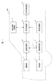
- FIG. 1 is a functional block diagram of the auto light system of the present embodiment mounted on the vehicle 100.
- the autolight system includes an imaging unit 1, an image processing unit 2, a vehicle information acquisition unit 3, a vehicle control unit 4, an illumination switching unit 5, an illumination control unit 6, and an illumination unit. 7 and a traveling system control unit 8 are connected to each other via a CAN (Controller (Area Network) which is a kind of vehicle bus.
- CAN Controller (Area Network) which is a kind of vehicle bus.
- the imaging unit 1 generates the same image data 10 when the driver of the vehicle 100 visually recognizes during driving, and is, for example, a monocular camera installed at the tip of the vehicle 100. Image data 10 captured by the imaging unit 1 is transmitted to the image processing unit 2 and recorded.
- the image processing unit 2 also functions as a camera control ECU (Electronic Control Unit), and controls the behavior of the imaging unit 1 by transmitting setting information such as imaging timing and imaging time of the imaging unit 1. .
- the image processing unit 2 generates light mode information corresponding to the image data 10 and transmits the light mode information to the illumination control unit 6. Details of these processes will be described later.
- the vehicle information acquisition unit 3 acquires vehicle information such as the speed and steering angle of the vehicle 100 via the above-described CAN and transmits the vehicle information to the vehicle control unit 4.
- the vehicle control unit 4 is based on various information (steering angle, speed, inter-vehicle distance, brake, etc.) acquired from the image processing unit 2, the vehicle information acquisition unit 3, the illumination control unit 6, and the travel system control unit 8. Output an appropriate command.
- the illumination switching unit 5 generates desired light mode information according to the driver's operation and transmits it to the illumination control unit 6.
- the illumination control unit 6 is also referred to as a lamp control ECU (Electronic Control Unit), and receives light mode information from the image processing unit 2 and the illumination switching unit 5. Further, the vehicle control unit 4 receives light mode information based on a control state such as a traveling state of the vehicle 100. The illumination control unit 6 sets the illumination unit 7 to an appropriate light mode based on any light mode information.
- a lamp control ECU Electronic Control Unit
- the illumination unit 7 is a headlight or a small light of the vehicle 100 and is set to a light mode corresponding to the light mode information input to the illumination control unit 6.
- the headlight is set to one of low beam, high beam, and extinguished, and the small light is set to either on or off.
- the illumination unit 7 may use a halogen lamp or a plurality of LEDs (light emitting diodes). When an LED is used, the irradiation region may be divided into small portions to define the irradiation region in detail. .
- the traveling system control unit 8 is connected to an engine, a motor, a steering mechanism, a brake mechanism, and the like (not shown), and transmits a driver's steering operation and acceleration / deceleration operation to the vehicle control unit 4 and also includes a vehicle control unit. In accordance with the steering command and acceleration / deceleration command from 4, the steering mechanism, the brake mechanism and the like are operated.
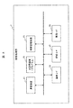
- FIG. 2 is a functional block diagram of the image processing unit 2 described above.
- the image processing unit 2 includes an arithmetic device 21, a main storage device 22 that stores a program and the like to be described later, an auxiliary storage device 23, and an imaging interface connected to the imaging unit 1 (hereinafter referred to as “imaging”).
- imaging an imaging interface connected to the imaging unit 1 (hereinafter referred to as “imaging”).
- a lighting interface connected to the lighting control unit 6 hereinafter referred to as” lighting I / F 25 "
- vehicle I / F 26 vehicle interface connected to the vehicle control unit 4
- the auxiliary storage device 23 of the image processing unit 2 stores the image data 10 in front of the vehicle imaged by the imaging unit 1 via the imaging I / F 24, and the arithmetic unit 21 performs the operation on the stored image data 10. Perform the processing specified by the program.
- the arithmetic unit 21 generates light mode information corresponding to the recognition result of the brightness in front of the vehicle 100 and transmits the light mode information to the illumination control unit 6 via the illumination I / F 25.
- the lighting control unit 6 in FIG. 1 that has received the light mode information controls the lighting unit 7 based on the received information.
- the light mode of the illumination unit 7 can be automatically switched according to the image data 10 captured by the imaging unit 1.
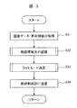
- FIG. 3 is a flowchart showing an outline of processing in the image processing unit 2.
- the image processing unit 2 first acquires the image data 10 and the vehicle information (S31), and then recognizes the brightness of ambient ambient light of the vehicle 100 from them (S32). The corresponding light mode is determined (S33), and the corresponding light mode information is transmitted to the illumination control unit 6 (S34).
- S31 “Acquisition of Image Data / Vehicle Information”>
- the image processing unit 2 acquires the image data 10 from the imaging unit 1 via the imaging I / F 25, and the vehicle information from the vehicle information acquisition unit 3 via the vehicle control unit 4 and the vehicle I / F 27.
- the image processing unit 2 recognizes ambient ambient light in front of the host vehicle using the image data 10 and vehicle information acquired in S31 (S32).
- ambient light can be estimated based on exposure characteristics and exposure values (brightness of acquired image, shutter speed, gain), and the brightness value is the same as that of a luminance meter. It can be detected.
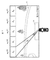
- FIG. 5 is an example of a determination area set in the image data 10, and an example in which an upper area 11 that mainly detects brightness at a long distance and a lower area 12 that mainly detects brightness at a short distance is set. Show.
- the image data 10 is equally divided, and the upper half is the upper region 11 and the lower half is the lower region 12.
- the ratio of each may be changed as appropriate.
- the upper region 11 is a region for measuring ambient light at a long distance based on the brightness of the sky, it is desirable that the upper region 11 can be processed so as to capture only the sky without capturing surrounding trees, signboards, buildings, and the like. . Therefore, in this embodiment, a plurality of upper measurement areas A 0 to A 4 having a height of about 1/5 of the vertical size of the image are installed above the upper area 11 so that surrounding trees, signboards, buildings, etc. It is possible to extract only the brightness of the sky in front of the vehicle. However, if the vertical size of each upper measurement area is made too small (for example, 1/10, 1/20), the accuracy in calculating the brightness of the sky may deteriorate, so the height of the entire measurement area It is about 1/5 of the vertical size.
- the lower area 12 is an area for measuring ambient ambient light at a short distance based on the brightness of the road surface 3 to 5 m ahead of the vehicle 100, so that it does not show surrounding trees or white lines, etc. It is desirable to be able to process so that only a short-distance road located in Therefore, in the present embodiment, the lower measurement area 120 having a height of about 1/7 of the vertical image size and a width of about 1/3 of the horizontal image size is provided below the lower area 12 to thereby The influence of trees, white lines, etc. has been reduced so that only the brightness of the road surface in front of the vehicle can be extracted.
- the steering angle ⁇ is acquired from the vehicle information, and the traveling direction of the vehicle 100 is determined.
- the traveling direction of the vehicle 100 is taken into consideration, and a weight w considering the deviation from the traveling direction is assigned to each of the upper measurement areas A 0 to A 4 .
- the environmental light in the traveling direction of the vehicle 100 is weighted and calculated.
- the steering angle ⁇ that the vehicle 100 can take can be classified into any of the steering angles ⁇ 0 to ⁇ 4 each having a predetermined width as shown in FIG.
- Each of the upper measurement areas A 0 to A 4 set in the upper area 11 corresponds to each of the steering angles ⁇ 0 to ⁇ 4. Therefore, if the steering angle ⁇ indicating the current traveling direction is obtained from the vehicle information, Any of the upper measurement areas corresponding to the traveling direction can be specified.
- the steering angle ⁇ is included in the steering angle ⁇ 2 , so that the upper measurement area A 2 can be specified as an area corresponding to the traveling direction.
- the steering angle ⁇ is included in the steering angle ⁇ 0, and therefore the upper measurement area A 0 can be specified as an area corresponding to the traveling direction.
- a weight considering the deviation from the traveling direction of the vehicle 100 is assigned to each upper measurement area. This assigns the maximum weight to the region corresponding to the traveling direction, and assigns a small weight to the region away from the traveling direction.
- the weight w is assigned to the other areas.
- the ambient light at a long distance is calculated from the brightness of the upper region 11 of the image data 10, and the ambient light at a short distance is calculated from the brightness of the lower region 12.
- the brightness of each measurement area can be calculated from the brightness, shutter speed, gain, and the like of the image data 10, but the brightness may be obtained by other methods.
- Equation 1 The specific calculation of ambient light at a long distance in S44 is according to Equation 1.
- Equation 1 the left side is the brightness of ambient ambient light, the right side x i is the average value of the brightness of each measurement area, w i is the weight of each measurement area, n is the number of upper measurement areas, and mi is the darkest This is a noise removal coefficient for excluding the upper measurement region.
- Equation 1 the weight w i is defined by Equation 2, and the noise removal coefficient m i is defined by Equation 3.
- the image data 10 may be calculated in consideration of the lower measurement region 120 corresponding to the short-distance ambient light and ignoring the depth component of the light. As a result, even when the vehicle 100 is traveling on a sharp curve, it is possible to avoid over-evaluation of the upper measurement area corresponding to the traveling direction and to appropriately estimate the ambient environment light.
- FIGS. 5 to 7 illustrate an example in which five upper measurement areas are provided
- the number of upper measurement areas may be increased or decreased according to the accuracy required for detecting ambient light.
- the weight w may be a binary value of “1” and “2”, and the weight w of each area may be assigned according to Equation 4.
- the brightness is calculated by the luminance average value of the lower measurement region 120.
- the light mode corresponding to the brightness of each ambient environment light is individually determined in S45.
- FIG. 8A is a schematic diagram showing the relationship between the brightness [cd / m 2 ] of the upper region 11 and the light mode, and when the brightness exceeds the upper threshold th_u1, “light OFF” is selected, “Small light ON” is selected between the upper threshold th_u1 and the upper threshold th_u2, and “headlight ON” is selected below the upper threshold th_u2.
- FIG. 8B is a schematic diagram showing the relationship between the brightness [cd / m 2 ] of the lower region 12 and the light mode, and “light OFF” is selected when the brightness exceeds the lower threshold th_d1, “Small light ON” is selected between the lower threshold th_d1 and the lower threshold th_d2, and “headlight ON” is selected below the lower threshold th_d2.
- the upper threshold value th_u1 of FIG. 8A is set to 150 [cd / m 2 ], taking into account the lens, shutter speed, gain, and the like of the imaging unit 1.
- th_u2 is set to 70 [cd / m 2 ]
- the lower threshold th_d1 of FIG. 8B is set to 100 [cd / m 2 ]
- the lower threshold th_d2 is set to 40 [cd / m 2 ].
- FIG. 9 is a flowchart showing another method of determining the write mode of the upper region 11
- FIG. 10 is a flowchart showing another method of determining the write mode of the lower region 12.
- FIG. 9 is a flowchart for determining the light mode based on the ambient ambient light obtained in the upper region 11.
- S91 it is determined whether the brightness of the ambient ambient light is equal to or higher than the upper threshold th_u1, and when this is satisfied, the average hue of the upper measurement areas A 0 to A 4 is calculated in S92.
- S93 it is determined whether the obtained average hue is within a predetermined hue range (180 ⁇ H ⁇ 270). If the average hue is satisfied, it is determined that the ambient ambient light is blue, that is, daytime and clear sky. The light mode is set to “light OFF” (S97). If the condition of S93 is not satisfied, it is determined that the ambient environment light is red or orange, that is, it is estimated to be evening, and the light mode is set to “small light ON” (S98).
- S94 it is determined whether the brightness of the ambient environment light is equal to or higher than the upper threshold th_u2 which is smaller than the upper threshold th_u1, and if this is satisfied, it is determined that the ambient environment light is dim, that is, it is estimated to be rainy weather or the like. Then, the light mode is set to “small light ON” (S98). If the condition of S94 is not satisfied, it is determined that the ambient light is slight, that is, it is estimated that it is nighttime, and the light mode is set to “headlight ON” (S99).
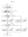
- FIG. 10 is a flowchart for determining the light mode based on the ambient environment light obtained in the lower region 12.
- S101 it is determined whether the brightness of the ambient environment light is equal to or higher than the lower threshold th_d1, and when this is satisfied, the light mode is set to “light OFF” (S103). If the condition of S101 is not satisfied, it is determined in S102 whether the brightness of the ambient ambient light is equal to or greater than the lower threshold th_d2 smaller than the lower threshold th_d1, and if this is satisfied, the light mode is set to “Small Light ON”. (S104). If the condition of S102 is not satisfied, the write mode is set to “headlight ON” (S105).
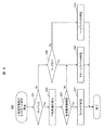
- FIG. 11 is a flowchart showing details of the S33 “write mode determination” process of FIG. Here, based on the light mode based on each of the upper region 11 and the lower region 12 obtained in S32, the light mode actually set for the illumination unit 7 is determined.
- FIG. 12 is a flowchart showing details of the S111 “light mode hunting prevention” process of FIG. 11, and the light mode of the illumination unit 7 is shortened by applying the hunting prevention process to the light mode in the upper and lower regions according to this. Avoid the problem of switching from time to time.
- the safety standard revised in October 2016 requires automatic lighting within 2 seconds when the ambient illuminance is less than 1000 [lx], so the determination period of whether lighting is necessary is 2 seconds. There is no problem even if fixed to. However, if the determination cycle is fixed to 2 seconds, for example, even if you enter a tunnel when driving on a highway, the headlights will not light up unless after traveling a considerable distance. Is also possible. Therefore, in this embodiment, the determination cycle is shortened during high-speed traveling, the response of the illumination unit 7 is accelerated, and the driver is not given a sense of incongruity.
- a determination cycle t that is approximately inversely proportional to the speed of the vehicle 100 is calculated. Note that the determination period t calculated here becomes shorter as the vehicle speed increases, and approaches 2 seconds as the vehicle speed decreases, and is calculated by, for example, Expression 5.
- s on the right side is vehicle speed [m / second]
- T is 2 [seconds]
- ⁇ is a variable for adjusting the shortest cycle
- t on the left side is a set determination cycle.
- the determination cycle t corresponding to the speed is calculated in S121, it is determined in S122 whether the light mode has changed in the upper and lower regions within the determination cycle t. If the light mode changes, it is determined that the determination in that region is unstable, and the light mode of the previous determination cycle is maintained (S123). On the other hand, if the write mode does not change within the determination cycle t, it is determined that the determination in that region is stable, and the write mode is updated to the current determination cycle (S124). Since the determination in S122 is performed independently for each of the upper and lower regions, one may maintain the write mode of the previous cycle and the other may be updated to the write mode of the current cycle.
- the write modes in the upper and lower areas after the processing in S122 to S124 are compared to determine whether they are the same. If both are the same, the write mode is set as the output of S111 (S126). On the other hand, if they are different, the write mode of the previous determination cycle is set as the output of S111 (S127).
- the light mode is determined using thresholds based on the inter-vehicle distance from the preceding vehicle (upper thresholds th_u1, th_u2, etc. in FIG. 8A).
- the threshold for determining the light mode is adjusted in consideration of the inter-vehicle distance so that an appropriate light mode can be set regardless of the inter-vehicle distance.
- FIG. 14 is a flowchart showing the detailed processing of S112 “light mode determination at short vehicle distance”.
- S141 it is determined whether the conditional statement 1 is satisfied. Since the conditional statement 1 is a conditional statement for avoiding accidental lighting of the light during a traffic jam, its contents are defined in the following two parts.
- Conditional statement 1a The vehicle speed is stopped, low speed, or decelerating.
- Conditional statement 1b The current light mode is “light OFF”. Since the ratio of the preceding vehicle 13 is small and the ambient environment light can be accurately detected from the upper and lower regions, or it can be estimated that the ambient environment is dark and the illumination unit 7 is already lit, the process of S112 is not performed.
- the number of low luminance pixels referred to here is the number of low luminance pixels having a pixel value of 40 (8 bits) or less included in the upper measurement regions A 0 to A 4 .
- the reason for correcting the determination threshold in consideration of the number of low-luminance pixels is that when the vehicle color of the preceding vehicle 13 is white or light color with high reflectance, the light mode determination is performed even if the vehicle is close to the preceding vehicle 13 due to traffic jams or the like.
- the inter-vehicle distance from the black or dark preceding vehicle 13 is estimated from the number of low-luminance pixels in the upper measurement areas A 0 to A 4 , and the upper thresholds th_u1 and th_u2 are corrected according to the predicted inter-vehicle distance (S142). ).
- the correction formula for the determination threshold used here is as shown in Expression 6.
- th_new is the corrected determination threshold
- th is the initial determination threshold
- s is the vehicle speed
- R is the threshold adjustment range
- D is the number of low luminance pixels in the upper measurement area A 0 to A 4
- ⁇ is the adjustment variable. is there.
- the determination threshold th is corrected in S142, the light mode for the upper region 11 is determined by the same method as in S45 of FIG. 9, and then the light mode hunting prevention processing is performed by the same method as in S111 of FIG. In this way, when the vehicle color of the preceding vehicle 13 and the distance between the preceding vehicle 13 are taken into consideration and the threshold value used for the determination of the light mode is corrected, it seems that the vehicle stopped immediately after the black preceding vehicle 13 in a traffic jam. Even in situations, it is possible to avoid malfunctions such as accidentally turning on the headlights.
- FIG. 15 is a flowchart showing the detailed processing of “write mode confirmation” in S113.
- S151 it is determined whether the conditional statement 2 is satisfied.
- Conditional sentence 2 is a conditional sentence for determining whether the lighting unit 7 needs to be turned off, and is defined by the following two sentences.
- Conditional statement 2a The last final determination is “Small light ON” or “Head light ON” ⁇
- Condition 2b This time the final decision is “light off”
- the turn-off time calculated here can be calculated using Equation 5 in the same way as the turn-on time.
- the initial value T of the turn-off time is any one of 5 to 300 seconds in consideration of the automatic turn-off time determined by the safety standard. Value is set.
- the illumination unit 7 After the processing of S152, or when the conditional statement 2 is not satisfied (maintenance of light extinction, maintenance of lighting, or lighting from extinction), it is determined whether or not the final determination of this time is “light OFF” (S153). When the final determination is “light OFF”, the elapsed time is counted up (S154), and when the elapsed time matches the extinguishing time set in S152 (S155), the extinguishing time is initialized (S156), “Light OFF” is output (S157). Thereby, the illumination unit 7 can be kept on before the predetermined time elapses, and the illumination unit 7 can be turned off when the predetermined time elapses.
- the brightness of ambient light cannot be accurately evaluated according to the conventional method, when driving on a sharp curve, or when the distance between the preceding vehicle is small, etc. Even in such a case, the brightness of the ambient environment light can be accurately evaluated, so that appropriate automatic light control can be realized without causing the driver to feel uncomfortable.
- the example in which the brightness of the ambient environment light is measured using the imaging unit 1 that captures the front is described.
- the brightness of the ambient environment light is measured using the rear camera of the vehicle 100.
- the light mode information may be generated.
- a monocular camera is used as the imaging unit 1.
- a stereo camera is used as the imaging unit 1, and the inter-vehicle distance from the preceding vehicle is accurately measured using the stereo camera.
- the light mode is determined based on this.
- duplication description is abbreviate
- the vehicle 100 according to the present embodiment has a configuration including two cameras 1a and 1b (hereinafter referred to as “stereo cameras”) having the same optical system.
- stereo cameras two cameras 1a and 1b
- FIG. 16A is an example in which a stereo camera is built in the illumination unit 7 of the vehicle 100
- FIG. 16B is an example in which the stereo camera is attached to the indoor ceiling of the vehicle 100.
- the vehicle 100 according to the present embodiment can record information on the measurement distance by simultaneously imaging the front from a plurality of different directions.
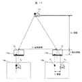
- the principle of triangulation is used as shown in FIG. That is, when the measurement object 171 is imaged, the image data 10a of the measurement object 171 is imaged by the two-dimensional sensor 172a of the left camera 1a, and the image data of the measurement object 171 is acquired by the two-dimensional sensor 172b of the right camera 1b. 10b is imaged.
- the baseline distance is B (m)
- the focal length is f (pixel)
- the imaging positions of the same part of the measurement object 171 on each image data are respectively X
- the distance Ds from the stereo camera to the measurement object 171 can be calculated by Equation 7.
- the distance Ds to the preceding vehicle is measured with the stereo camera, and when the distance Ds is less than the predetermined threshold, it is determined that the preceding vehicle amount is close and the lighting or extinguishing is determined.
- the threshold values of the brightness of the ambient environment light (upper threshold values th_u1, th_u2) used for the correction are corrected.
- the image data 10 and the vehicle information are acquired (S31) and ambient light is recognized (S32), as in FIG. 3 of the first embodiment. Then, the light mode determination process (S33) of the present embodiment shown in FIG. 18 is performed, and finally the lighting unit 7 is controlled to be turned on / off according to the light mode determined by the method of the present embodiment (S34). .
- the “write mode determination” process of the present embodiment shown in FIG. 18 explains S112 “determination of low speed” in FIG. 11 for explaining “write mode determination” of the first embodiment, and S181 “determination of adjacent preceding vehicle” in FIG. ". Note that the processing in S111 in FIG. 18 and the processing in S113 are the same as those in FIG.
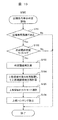
- FIG. 19 is a flowchart showing details of the “determination of a proximity vehicle” process in S181.
- S191 it is determined whether the inter-vehicle distance Ds is within the range of a preset close inter-vehicle distance (for example, 15 m). If not, the threshold for determining the light mode is changed. The process of S181 is terminated without doing so. If the inter-vehicle distance Ds is within the preset approaching inter-vehicle distance range, in S192, it is determined whether the light mode determined in the previous determination cycle is “light OFF”. Is “Headlight ON” or “Small Light ON”), the process of S181 ends without changing the threshold value for determining the write mode.
- the determination threshold is recalculated using Equation 8 in S193.
- Th_new of formula 8 recalculated determination threshold
- th the original determination threshold value
- R represents the adjustment range of the threshold
- Ds is the inter-vehicle distance
- D f is a preset distance range (the timing of the approaching vehicle determination process)
- ⁇ are calculation adjustment variables.
- Equation 9 the left side is the upper ambient ambient light, the right side x i is the average brightness of each measurement area, w i is the weight distribution of each measurement area by the approaching vehicle, and n is the number of installation measurement areas.
- the weight distribution w i of each measurement region is defined by Equation 10.
- the light mode of the upper region 11 is selected using the threshold value recalculated in S193 and the upper ambient light calculated in S194.
- the anti-hunting process is performed by the same method as in FIG. Then, the process of S181 ends, and the process proceeds to the write mode determination process (S113) of FIG.
- the inter-vehicle distance is estimated by calculation, and the light mode is determined.
- the inter-vehicle distance is determined by using a stereo camera. It is possible to accurately measure and set the light mode more appropriately based on this accurate inter-vehicle distance. As a result, it is possible to suppress the situation where the light is turned on unnecessarily as compared with the first embodiment, it is possible to suppress the waste of the battery, and it is possible to perform the light control that matches the sense of the driver.
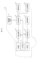
- FIG. 20 is a block diagram of the auto light system of this embodiment.
- the inter-vehicle distance from the preceding vehicle is measured using a stereo camera, and the light mode is determined using a threshold value corresponding thereto.
- the radar distance measuring unit 1A is used to The inter-vehicle distance is measured, and the light mode is determined using a threshold value corresponding thereto. Since the processing routine of the present embodiment is the same as that described in FIGS. 18 and 19 of the second embodiment, the duplicate description is omitted.
- the radar ranging unit 1A performs ranging by receiving light such as millimeter wave radar or LIDAR (LightIDDetection and Ranging) and receiving the reflected light.
- the image processing unit 2a of the present embodiment is obtained by adding a radar ranging I / F 27 for connection to the radar ranging unit 1A to the configuration of the image processing unit 2 shown in FIG.
- the inter-vehicle distance is accurately measured, and the light mode is more appropriately determined based on the accurate inter-vehicle distance. Can be set. As a result, it is possible to suppress battery waste and to perform light control that matches the driver's feeling.
- Embodiment 4 of the present invention is different from the above-described embodiment in that map information and in-house position information are used when determining the light mode.
- duplication description is abbreviate
- FIG. 22 is a block diagram of the auto light system of the present embodiment. As shown here, the auto light system of the present embodiment is obtained by adding a map cooperation unit 3a to the configuration of the first embodiment, and correspondingly, the image processing unit 2 is replaced with an image processing unit 2b. is there.
- FIG. 23 is a functional block diagram showing the image processing unit 2b of the present embodiment.
- the image processing unit 2b according to the present embodiment is substantially the same as the image processing unit 2 according to the first embodiment, but includes a map cooperation I / F 28 for connecting to the map cooperation unit 3a.
- FIG. 24 is a functional block diagram of the map linkage unit 3a.
- the map linkage unit 3a includes an arithmetic device 241, a main storage device 242 storing a map database and a program, an auxiliary storage device 243, an image / display I / F 244, and a GPS receiver (not shown).
- a positioning I / F 245 for receiving a positioning signal from the camera, a sensing I / F 246 for receiving outside information from the imaging unit 1 and the radar ranging 1A, and a vehicle I / F 247.
- This map linkage unit 3a transfers the vehicle information (speed, etc.), GPS satellite reception information, and other sensing information (for example, image data in front of the vehicle, radar ranging, etc.) to the auxiliary storage device 243 for storage. At the same time, the vehicle position / traveling direction is estimated based on the information stored there. In addition, the arithmetic device 241 transmits a control signal to a desired interface based on a program stored in the main storage device 242. The own vehicle position and the traveling direction estimated by the arithmetic unit 241 are transmitted to the image / display I / F 234 together with the map information.
- the map linkage unit 3a calculates (positions) the vehicle position as an absolute coordinate based on the positioning signal, and calculates the vehicle position as a relative change from the position based on the outside information. Further, using the map database, a map matching process for correcting the calculated vehicle position to a position on the map road is performed. As a result of these processes, the map cooperation unit 3a can estimate the traveling direction with high accuracy based on the estimated position of the vehicle on the road and the direction information.
- the illumination position in the tunnel is input to the image processing unit 2b via the map cooperation I / F 28.
- the weight of the upper measurement area and the threshold for determining the light mode can be switched in advance, or the headlight can be turned on in advance in places where lighting such as tunnels is mandatory. Further, the switching of the light mode can be made more appropriate, and the driver's comfort can be further enhanced.
- this invention is not limited to the above-mentioned Example, Various modifications are included.
- the above-described embodiments have been described in detail for easy understanding of the present invention, and are not necessarily limited to those having all the configurations described.
- a part of the configuration of one embodiment can be replaced with the configuration of another embodiment, and the configuration of another embodiment can be added to the configuration of one embodiment.
Landscapes
- Engineering & Computer Science (AREA)
- Physics & Mathematics (AREA)
- General Physics & Mathematics (AREA)
- Theoretical Computer Science (AREA)
- Mechanical Engineering (AREA)
- Multimedia (AREA)
- Software Systems (AREA)
- Computer Vision & Pattern Recognition (AREA)
- Lighting Device Outwards From Vehicle And Optical Signal (AREA)
- Traffic Control Systems (AREA)
Abstract
車速、操舵角度など情報を用いて周囲の明るさを判定し、運転者に違和感を与えないオートライト制御を実現する。また、車両走行中に急激な環境変換や及び先行車の影響による誤動作を防止する。周囲環境に応じて車両の照明を自動的に点灯または消灯するオートライトシステムであって、前記車両の前方を撮像し画像データを生成する撮像装置と、該画像データの上部領域と下部領域の明るさに基づいて前記照明の点灯又は消灯を制御するライトモード情報を生成する画像処理部と、該ライトモード情報に基づいて前記照明を制御する照明制御部と、を備えており、前記画像処理部は、前記上部領域に設定した複数の測定領域のうち、前記車両の進行方向の測定領域の重みを重く、他の測定領域の重みを軽くして、前記上部領域の明るさを演算し、該上部領域の明るさに基づいて前記ライトモード情報を生成するオートライトシステム。
Description
本発明は、周囲環境に応じて車両の照明を自動的に点灯または消灯するオートライトシステムに関する。
2016年10月に改正された道路運送車両の保安基準では、2020年4月以降に販売を開始する新型乗用車への「オートライト機能」の搭載を義務付けている。同基準が義務付ける「オートライト機能」は、周囲環境の照度が1000[lx]未満の場合に2秒以内に自動点灯し、7000[lx]を超えた場合に5~300秒の範囲内で自動消灯するというものである。
ここで、従来の自動車用オートライトシステムとしては、車載カメラを利用して車外照度を検出し、それに応じてライトを自動点灯、または、自動消灯するものがある。
例えば、特許文献1の要約書には、「オートライト装置1は、自車前方を撮像する撮像手段2と、その撮像手段2により撮像した自車前方の画像に基づいてヘッドライト等のライト類を点灯又は消灯するライト制御手段3を有する。そして、撮像手段2により撮像した自車前方の画像に基づいて、運転者が見ている自車前方の明るさを認識し、その自車前方の明るさに基づいて、ライト類101を点灯又は消灯させるライト制御を行う。」と記載されており、自車前方の明るさに応じて、ライト類を自動点灯または自動消灯させる技術が開示されている。
ここで、特許文献1の従来技術は、例えば、同文献の請求項8や図7で説明されるように、主に路面の撮像データを基に、周囲環境光の明るさを予測するものである。この場合、路面ペイントの状態や、建物や高架下の影、或いは、先行車の存在などの影響で、算出される明るさが刻々と変化するため、所定時間の平均化処理などにより、それらのノイズの影響を除去しているが、以下の項目が依然課題として残っている。
まず、通常走行中、道路の状況、色や先行車両の影響など道路領域を正しく検知できないとオートライトの誤動作を起こす可能性がある。例えば、急カーブの走行時のように操舵角度が大きい場合は、車載カメラが撮像する路面状態が短時間で大きく変化するため、周囲環境の明るさの判定が不適切となり、ヘッドライトの点灯タイミングが遅れる恐れがある。
また、先行車との車間距離が小さく、車載カメラの画像データに占める先行車の割合が大きい場合も、路面を十分に撮像できず、その画像データに基づいて設定したライトモードが適切でなくなる場合がある。
本発明は、以上の問題を鑑みてなされたものであり、車両が急カーブを走行する場合や、先行車量との車間距離が小さい場合であっても、適切なライトモードを設定できるオートライトシステムを提供することを目的とする。
上記課題を解決するため、本発明のオートライトシステムは、周囲環境に応じて車両の照明を自動的に点灯または消灯するものであって、前記車両の前方を撮像し画像データを生成する撮像装置と、該画像データの上部領域と下部領域の明るさに基づいて前記照明の点灯又は消灯を制御するライトモード情報を生成する画像処理部と、該ライトモード情報に基づいて前記照明を制御する照明制御部と、を備えており、前記画像処理部は、前記上部領域に設定した複数の測定領域のうち、前記車両の進行方向の測定領域の重みを重く、他の測定領域の重みを軽くして、前記上部領域の明るさを演算し、該上部領域の明るさに基づいて前記ライトモード情報を生成するものとした。
本発明のオートライトシステムによれば、車両が急カーブを走行する場合や、先行車量との車間距離が小さい場合であっても、適切なライトモードを設定することができる。
以下、図面に基づき、本発明のオートライトシステムの実施例について詳細に説明する。
本発明の実施例1のオートライトシステムについて、図1~図15を用いて説明する。
図1は、車両100に搭載される、本実施例のオートライトシステムの機能ブロック図である。ここに示すように、本オートライトシステムは、撮像部1と、画像処理部2と、車両情報取得部3と、車両制御部4と、照明切換部5と、照明制御部6と、照明部7と、走行系制御部8を備えており、各々は、ビークルバスの一種であるCAN(Controller Area Network)等を介して相互に接続されている。
撮像部1は、車両100の運転者が運転中に視認すると同様の画像データ10を生成するものであり、例えば、車両100の先端に設置した単眼カメラである。撮像部1が撮像した画像データ10は、画像処理部2に送信され記録される。
画像処理部2は、カメラ制御用ECU(Electronic Control Unit)としても機能するものであり、撮像部1の撮像タイミングや撮像時間等の設定情報を送信することで、撮像部1の挙動を制御する。また、画像処理部2では、画像データ10に応じたライトモード情報を生成し、照明制御部6に送信するが、これらの処理の詳細は後述する。
車両情報取得部3は、上述したCAN等を介して車両100の速度や舵角等の車両情報を取得し、車両制御部4に送信する。
車両制御部4は、画像処理部2、車両情報取得部3、照明制御部6、走行系制御部8より取得した各種情報(舵角、速度、車間距離、ブレーキなど)に基づいて、各部に適切な指令を出力する。
照明切換部5は、運転者の操作に応じて、所望のライトモード情報を生成し、照明制御部6に送信する。
照明制御部6は、ランプ制御用ECU(Electronic Control Unit)とも称され、画像処理部2や照明切換部5からのライトモード情報を受信する。また、車両制御部4からは車両100の走行状態等の制御状態に基づくライトモード情報を受信する。照明制御部6は何れかのライトモード情報に基づき、照明部7を適切なライトモードに設定する。
照明部7は、車両100のヘッドライトやスモールライトであり、照明制御部6に入力されたライトモード情報に応じたライトモードに設定される。例えば、ヘッドライトは、ロービーム、ハイビーム、消灯の何れかに設定され、スモールライトは点灯、消灯の何れかに設定される。なお、照明部7は、ハロゲンランプを用いても、複数のLED(発光ダイオード)を用いてもよく、LEDを用いる場合は、照射領域を細かく分割し、照射領域を詳細に規定してもよい。
走行系制御部8は、図示しない、エンジン、モータ、ステアリング機構、ブレーキ機構等に接続されたものであり、運転者の操舵操作や加減速操作を車両制御部4に伝達するとともに、車両制御部4からの操舵指令や加減速指令に従って、ステアリング機構、ブレーキ機構等を操作するものである。
図2は、上述した画像処理部2の機能ブロック図である。ここに示すように、画像処理部2は、演算装置21と、後述するプログラム等を記憶した主記憶装置22と、補助記憶装置23と、撮像部1と接続される撮像インターフェース(以下、「撮像I/F24」)と、照明制御部6と接続される照明インターフェース(以下、「照明I/F25」)と、車両制御部4と接続される車両インターフェース(以下、車両I/F26」)を備えており、主記憶装置22から読み出したプログラムを、演算装置21が補助記憶装置23内で実行することで、後述する諸機能が実現される。
画像処理部2の補助記憶装置23には、撮像I/F24を介して、撮像部1が撮像した車両前方の画像データ10が記憶され、演算装置21は、記憶された画像データ10に対してプログラムが規定する処理を施す。その結果、演算装置21は、車両100の前方の明るさの認識結果に応じたライトモード情報を生成し、照明I/F25を介して照明制御部6に送信する。ライトモード情報を受信した図1の照明制御部6は、受信した情報に基づいて照明部7を制御する。このようにして、本実施例のオートライトシステムでは、撮像部1が撮像した画像データ10に応じて照明部7のライトモードを自動的に切り替えることができる。
次に、図3から図15を用いて、本実施例の画像処理部2での処理内容を詳細に説明する。
図3は、画像処理部2での処理の概略を示すフローチャートである。ここに示すように、画像処理部2では、先ず、画像データ10と車両情報を取得した後(S31)、それらから車両100の周囲環境光の明るさを認識し(S32)、その明るさに応じたライトモードを決定し(S33)、それに対応するライトモード情報を照明制御部6に送信する(S34)。以下、各々の処理を具体的に説明する。
<S31「画像データ・車両情報の取得」の処理>
S31では、画像処理部2は、撮像I/F25を介して撮像部1からの画像データ10を取得し、車両制御部4と車両I/F27を介して、車両情報取得部3からの車両情報(速度や舵角等)を取得する。
<S32「周囲環境光の認識」の処理>
続いて、S32では、画像処理部2は、S31で取得した画像データ10と車両情報を利用し、自車前方の周囲環境光を認識する(S32)。ここでの周囲環境光の認識は、露光特性と露光値(取得した画像の輝度、シャッタ速度、ゲイン)を基に輝度値を推定することが可能であり、その輝度値は輝度計と同様に検知可能である。
<S31「画像データ・車両情報の取得」の処理>
S31では、画像処理部2は、撮像I/F25を介して撮像部1からの画像データ10を取得し、車両制御部4と車両I/F27を介して、車両情報取得部3からの車両情報(速度や舵角等)を取得する。
<S32「周囲環境光の認識」の処理>
続いて、S32では、画像処理部2は、S31で取得した画像データ10と車両情報を利用し、自車前方の周囲環境光を認識する(S32)。ここでの周囲環境光の認識は、露光特性と露光値(取得した画像の輝度、シャッタ速度、ゲイン)を基に輝度値を推定することが可能であり、その輝度値は輝度計と同様に検知可能である。
S32の処理を、図4のフローチャートを用いて詳細に説明する。
まず、S41では、画像データ10の上部と下部のそれぞれに判定領域を設定する。図5は、画像データ10に設定した判定領域の一例であり、主に遠距離の明るさを検出する上部領域11と、主に近距離の明るさを検出する下部領域12を設定した例を示している。なお、この例では、画像データ10を等分し、上半分を上部領域11とし、下半分を下部領域12としているが、各々の割合は適宜変更しても良い。
上部領域11は、空の明るさ等に基づいて遠距離の周囲環境光を測定する領域であるため、周囲の木、看板、建物等を写さず、空のみを写すように処理できることが望ましい。そこで、本実施例では、上部領域11の上部に、画像縦サイズの1/5程度の高さの複数の上部測定領域A0~A4を設置することで、周囲の木、看板、建物等の影響を低減し、車両前方の空の明るさのみを抽出できるようにした。ただし、各上部測定領域の縦サイズをあまり小さくすると(例えば、1/10、1/20)、空の明るさを演算する際の精度が劣化する可能性があるので、その高さを全体画像縦サイズの1/5程度としている。
一方、下部領域12は、車両100の前方3~5mの路面の明るさ等に基づいて近距離の周囲環境光を測定する領域であるため、周囲の木や白線等を写さず、進行方向にある近距離の道路のみを写すように処理できることが望ましい。そこで、本実施例では、下部領域12の下部に、画像縦サイズの1/7程度の高さ、かつ、画像横サイズの1/3程度の幅の下部測定領域120を設置することで、周囲の木や白線等の影響を低減し、車両前方の路面の明るさのみを抽出できるようにした。
続いて、S42では、車両情報から舵角θを取得し、車両100の進行方向を判定する。S43では、車両100の進行方向を考慮し、上部測定領域A0~A4の各々に進行方向とのずれを考慮した重みwを割り当てる。S44では、車両100の進行方向の環境光を重み付けて計算する。
ここで、図6、図7を用いて、S42とS43の処理を具体的に説明する。車両100が取りうる舵角θは、図6に示す、各々所定の幅を持つ舵角θ0~θ4の何れかに分類できる。上部領域11に設定した上部測定領域A0~A4の夫々は、舵角θ0~θ4の夫々と対応するため、車両情報から現在の進行方向を示す舵角θを取得すれば、現在の進行方向に対応する何れかの上部測定領域を特定することができる。
例えば、図6の矢印に示すように、車両100が略直進走行している場合、舵角θは舵角θ2に含まれるため、上部測定領域A2を進行方向に対応する領域として特定できる。一方、図7のように、車両100が左向きの急カーブを走行している場合、舵角θは舵角θ0に含まれるため、上部測定領域A0を進行方向に対応する領域として特定できる。
進行方向に対応する上部測定領域を特定すると、各上部測定領域に対し、車両100の進行方向とのずれを考慮した重みを割り当てる。これは、進行方向に対応する領域に最大の重みを割り当て、進行方向から離れる領域には小さな重みを割り当てるというものである。例えば、図6の例では、進行方向と一致する上部測定領域A2に重みw=3を、これに隣接する上部測定領域A1、A3に重みw=2を、その他の領域に重みw=1を割り当てる。また、図7の例では、進行方向と一致する上部測定領域A0に重みw=3を、これに隣接する上部測定領域A1に重みw=2を、その他の領域に重みw=1を割り当てる。
図4のS44では、画像データ10の上部領域11の明るさから遠距離の周囲環境光を算出し、下部領域12の明るさから近距離の周囲環境光を算出する。なお、各測定領域の明るさは、画像データ10の輝度、シャッタ速度、ゲイン等から算出できるが、他の方法により明るさを求めても良い。
S44で遠距離の周囲環境光を推定する場合、まず、上部測定領域A0~A4の各々の明るさの通常平均値を求め、最も暗い領域を除外してから、加重平均値を算出し、それを遠距離の周囲環境光の明るさとする。このように、最も暗い領域のデータを除外することでノイズの影響を排除でき、また、進行方向からのずれの大きさを考慮して加重平均値を求めることで、遠距離の周囲環境光の計算精度を高めることができる。
S44での遠距離の周囲環境光の具体的な演算は、式1による。

式1において、左辺は周囲環境光の明るさ、右辺のxiは各測定領域の明るさの平均値、wiは各測定領域の重み、nは上部測定領域の数、miは最も暗い上部測定領域を除外するためのノイズ除去係数である。
また、式1中の、重みwiは式2で定義され、ノイズ除去係数miは式3で定義される。


また、図7の急カーブ走行例のように、5個の上部測定領域のうち、3個に重みw=1を割り当てる場合、あるいは1個にのみ重みw=2を割り当てる場合は、画像データ10の奥行成分を無視し、近距離の周囲環境光に相当する下部測定領域120も考慮して周囲環境光を計算しても良い。これにより、車両100が急カーブを走行中であっても、進行方向に相当する上部測定領域の過大評価を避け、周囲環境光を適切に推定できる。
なお、図5~図7では、上部測定領域を5個とした例を説明したが、周囲環境光の検出に求められる精度に応じて上部測定領域の設定数を増減させても良い。例えば、上部測定領域を3個とする場合、重みwを「1」と「2」の二値とし、各領域の重みwを式4に従って割り当てても良い。

一方、S44で画像データ10の下部領域12に基づいて近距離の周囲環境光を推定する場合、その明るさは下部測定領域120の輝度平均値で算出される。
S44で上部、下部の各領域について、周囲環境光の明るさを算出すると、S45では、それぞれの周囲環境光の明るさに応じたライトモードを個々に判定する。
ここで、図8Aは、上部領域11の明るさ[cd/m2]とライトモードの関係を示す概略図であり、その明るさが上閾値th_u1を超えるときに「ライトOFF」が選択され、上閾値th_u1と上閾値th_u2の間では「スモールライトON」が選択され、上閾値th_u2未満では「ヘッドライトON」が選択されることを示している。
同様に、図8Bは、下部領域12の明るさ[cd/m2]とライトモードの関係を示す概略図であり、その明るさが下閾値th_d1を超えるときに「ライトOFF」が選択され、下閾値th_d1と下閾値th_d2の間では「スモールライトON」が選択され、下閾値th_d2未満では「ヘッドライトON」が選択されることを示している。
すなわち、図8Aと図8Bの何れの場合も、周囲環境が明るければ「ライトOFF」が、暗ければ「ヘッドライトON」が選択され、その中間であれば「スモールライトON」が選択される。なお、上下の閾値は同値である必要はなく、本実施例では、撮像部1のレンズ、シャッタ速度、ゲイン等を考慮し、図8Aの上閾値th_u1を150[cd/m2]、上閾値th_u2を70[cd/m2]に設定し、図8Bの下閾値th_d1を100[cd/m2]、下閾値th_d2を40[cd/m2]に設定している。
また、S45で実行される上部領域11と下部領域12のライトモード判定には、図8A、図8B以外の手法を採用しても良い。図9は上部領域11のライトモード判定の他手法を示すフローチャートであり、図10は下部領域12のライトモード判定の他手法を示すフローチャートである。
図9は、上部領域11で求めた周囲環境光に基づいて、ライトモードを判定するフローチャートである。まず、S91では、周囲環境光の明るさが上閾値th_u1以上かを判定し、これを満たすときは、S92で、上部測定領域A0~A4の平均色相を算出する。平均色相の計算は上部測定領域A0~A4内の全画素数の色相平均ではなく、空を含む画像領域の色相のみを算出する。つまり、上部測定領域A0~A4内の飽和画素数(R=max, G=255, B=255)を除いて、平均色相を求める。
その後、S93では、求めた平均色相が所定の色相範囲(180<H<270)かを判定し、これを満たす場合には、周囲環境光が青色であると判定し、すなわち、日中かつ晴天であると推定し、ライトモードを「ライトOFF」とする(S97)。また、S93の条件を満たさない場合は、周囲環境光が赤色またはオレンジ色であると判定し、すなわち、夕方であると推定し、ライトモードを「スモールライトON」とする(S98)。
また、S94では、周囲環境光の明るさが、上閾値th_u1より小さい上閾値th_u2以上かを判定し、これを満たすときは、周囲環境光が薄暗いと判定し、すなわち、雨天等であると推定し、ライトモードを「スモールライトON」とする(S98)。S94の条件を満たさない場合は、周囲環境光が僅かと判定し、すなわち、夜間であると推定し、ライトモードを「ヘッドライトON」とする(S99)。
一方、図10は、下部領域12で求めた周囲環境光に基づいて、ライトモードを判定するフローチャートである。まず、S101では、周囲環境光の明るさが下閾値th_d1以上かを判定し、これを満たすときは、ライトモードを「ライトOFF」とする(S103)。また、S101の条件を満たさない場合は、S102で、周囲環境光の明るさが、下閾値th_d1より小さい下閾値th_d2以上かを判定し、これを満たすときは、ライトモードを「スモールライトON」とする(S104)。S102の条件を満たさない場合は、ライトモードを「ヘッドライトON」とする(S105)。
上述した何れかの手法により、上部領域11、下部領域12の夫々について、ライトモードを判別し、S45の処理が完了すると、図3のS32の全ての処理が完了し、S33の「ライトモード決定」の処理へと進む。
<S33「ライトモード決定」の処理>
図11は、図3のS33「ライトモード決定」処理の詳細を示すフローチャートである。ここでは、S32で求めた上部領域11と下部領域12の夫々に基づくライトモードを踏まえ、照明部7に実際に設定するライトモードを決定する。
<S33「ライトモード決定」の処理>
図11は、図3のS33「ライトモード決定」処理の詳細を示すフローチャートである。ここでは、S32で求めた上部領域11と下部領域12の夫々に基づくライトモードを踏まえ、照明部7に実際に設定するライトモードを決定する。
まず、S111の「ライトモードのハンチング防止」では、車両100の車速を考慮して、ライトモードのハンチング(ライトモードが短期間で次々と切り替わる事象)防止処理を行う。
図12は、図11のS111「ライトモードのハンチング防止」処理の詳細を示すフローチャートであり、これに従って、上下領域でのライトモードにハンチング防止処理を施すことで、照明部7のライトモードが短時間で次々に切り替わる不具合を回避する。
上述したように、2016年10月改正の保安基準は、周囲の照度が1000[lx]未満となった場合、2秒以内の自動点灯を求めているため、点灯要否の判定周期は2秒に固定しても問題はない。しかしながら、判定周期を2秒に固定すると、例えば、高速道路走行時にトンネルに進入しても、相当距離の走行後でなければヘッドライトが点灯しない等、安全面や運転者の感覚面での問題も考えられる。そこで、本実施例では、高速走行中は判定周期を短くし、照明部7の応答を早め、運転者に違和感を与えないようにしている。
これを実現するため、図12のS121では、車両100の速度に略反比例するような判定周期tを算出する。なお、ここで算出される判定周期tは、車速が増すほど短くなり、車速が遅くなるほど2秒に近づくものであり、例えば、式5により算出される。

ここで、右辺のsは車速[m/秒]、Tは2[秒]、αは最短周期を調整するための変数であり、左辺のtは設定される判定周期である。
S121で速度に応じた判定周期tを算出すると、S122では、その判定周期t内に、上下領域についてライトモードの変化があったかを判断する。そして、ライトモードが変化した場合は、その領域での判定が不安定と判断し、前回の判定周期のライトモードを維持する(S123)。一方、判定周期t内にライトモードが変化しない場合は、その領域での判定が安定していると判断し、今回の判定周期のライトモードに更新する(S124)。なお、S122の判断は、上下領域の各々に対し独立して行われるため、一方は前周期のライトモードを維持、他方は今周期のライトモードに更新、となる場合もある。
次に、S125では、S122~S124の処理後の上下部領のライトモードを比較し、両者が同一かを判断する。両者が同一であれば、そのライトモードをS111の出力とする(S126)。一方、両者が相違すれば、前回の判定周期のライトモードをS111の出力とする(S127)。
次に、図11のS112の「短車間距離時ライトモード判定」では、先行車との車間距離を踏まえた閾値(図8Aの上閾値th_u1、th_u2等)を用いて、ライトモードを判定する。
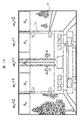
一般的に、車両100の速度と車間距離には関係があり、速度が速ければ車間距離が長くなり、遅ければ車間距離が短くなる傾向がある。図5のように先行車がおらず速度が速い状況では、上部測定領域A0~A4と下部測定領域120の何れにおいても周囲環境光を正確に検出できるが、図13のように先行車との車間距離が短い状況では、撮像部1が撮像した画像データ10の大部分が先行車13で占められ、本来の周囲環境光を正確に検出することが難しい。このため、渋滞時には、晴天時であるにもかかわらず、ライトモードが「ヘッドライトON」に設定される可能性もある。そこで、S112では、車間距離を考慮してライトモードを判定する際の閾値を調整し、車間距離の大小に拘わらず適当なライトモードを設定できるようにした。
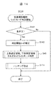
図14は、S112「短車間距離時ライトモード判定」の詳細処理を示すフローチャートである。まず、S141では、条件文1を満たすか否かを判定する。条件文1は、渋滞中に誤ってライトが点灯するのを避けるための条件文であるため、その内容は、次の二分で定義される。
・条件文1a:車速は、停止、低速、または、減速中であること
・条件文1b:現状のライトモードが「ライトOFF」であること
条件文1を満たさないときは、画像データ10に占める先行車13の割合は小さく、上下領域から周囲環境光を正確に検出できるか、周囲環境が暗く既に照明部7が点灯している状態と推測できるため、S112の処理が行われない。一方、条件文1を共に満たすときは、渋滞により画像データ10に占める先行車13の割合が大きくなっている可能性もあるため、誤って照明部7を点灯しないように、ライトモードを判定するための閾値を補正する(S142)。
・条件文1a:車速は、停止、低速、または、減速中であること
・条件文1b:現状のライトモードが「ライトOFF」であること
条件文1を満たさないときは、画像データ10に占める先行車13の割合は小さく、上下領域から周囲環境光を正確に検出できるか、周囲環境が暗く既に照明部7が点灯している状態と推測できるため、S112の処理が行われない。一方、条件文1を共に満たすときは、渋滞により画像データ10に占める先行車13の割合が大きくなっている可能性もあるため、誤って照明部7を点灯しないように、ライトモードを判定するための閾値を補正する(S142)。
S142での判定閾値の補正時には、車両100の速度と画像データ10中の低輝度画素数を考慮する。ここで言う低輝度画素数とは、上部測定領域A0~A4に含まれる画素値40(8bit)以下の低輝度のピクセルの数である。低輝度画素数を考慮して判定閾値を補正する理由は、先行車13の車体色が反射率の高い白色や明色である場合、渋滞等により先行車13と近接してもライトモード判定に悪影響がないのに対し、先行車13の車体色が反射率の低い黒色や暗色である場合は、車間距離がライトモード判定の適否に大きく影響するからである。このため、黒色または暗色の先行車13との車間距離を上部測定領域A0~A4中の低輝度画素数から推測し、予測した車間距離に応じて上閾値th_u1、th_u2を補正する(S142)。ここで用いる判定閾値の補正式は式6に示すとおりである。

ここで、th_newは補正した判定閾値、thは初期の判定閾値、sは車速、Rは閾値の調整範囲、Dは上部測定領域A0~A4内の低輝度画素数、αは調整変数である。
S142で判定閾値thを補正すると、図9のS45と同様の手法により上部領域11に対するライトモードを判定し、その後、図12のS111と同様の手法によりライトモードのハンチング防止の処理を行う。このようにして先行車13の車体色、および、先行車13との車間距離を考慮し、ライトモードの判定に利用する閾値を補正すると、渋滞時に黒色の先行車13の直後に停止したような状況であっても、誤ってヘッドライトを点灯するような誤動作を回避できる。
次に、図11のS113の「ライトモード確定」では、S111,S112の処理の出力であるライトモードを基に、照明部7に設定するライトモードを最終的に確定する。
図15は、S113の「ライトモード確定」の詳細処理を示すフローチャートである。ここに示すように、S151では条件文2を満たすか判定する。条件文2は、照明部7を消灯する必要があるかを判断するための条件文であり、次の二文で定義される。
・条件文2a:前回最終判定は「スモールライトON」か「ヘッドライトON」
・条件文2b:今回最終判定は「ライトOFF」
条件文2を共に満たすときは、照明部7を点灯から消灯に切り替えるタイミングであるため、車速に応じた消灯までの所要時間を計算する(S152)。ここで計算する消灯時間も点灯時間と同様に、式5を用いて演算できるが、消灯時間の初期値Tには、保安基準が定める自動消灯時間を考慮し、5~300秒の何れかの値が設定される。
・条件文2a:前回最終判定は「スモールライトON」か「ヘッドライトON」
・条件文2b:今回最終判定は「ライトOFF」
条件文2を共に満たすときは、照明部7を点灯から消灯に切り替えるタイミングであるため、車速に応じた消灯までの所要時間を計算する(S152)。ここで計算する消灯時間も点灯時間と同様に、式5を用いて演算できるが、消灯時間の初期値Tには、保安基準が定める自動消灯時間を考慮し、5~300秒の何れかの値が設定される。
S152の処理後、或いは、条件文2を満たさないとき(消灯維持、点灯維持、または、消灯から点灯)には、今回の最終判定が「ライトOFF」かを判定する(S153)。最終判定が「ライトOFF」である場合は、経過時間をカウントアップし(S154)、経過時間がS152で設定した消灯時間に一致したときに(S155)、消灯時間を初期化(S156)し、「ライトOFF」を出力する(S157)。これにより、所定時間の経過前は照明部7を点灯維持し、所定時間の経過時は照明部7を消灯できる。
一方、S153の判定がNoである場合、すなわち、最終判定が「スモールライトON」、「ヘッドライトON」の何れかである場合には、当面消灯は必要ないので、S152で消灯時間を設定していた場合であってもそれを初期化(S158)し、「スモールライトON」か「ヘッドライトON」の何れかを出力する(S159)。
図15の一連の処理(S113)を終えライトモードが確定すると、図11の一連の処理(S33)も終了し、図3のS34の処理に進む。
<S34「照明制御部に送信」の処理>
図3のS34の「照明制御部に送信」の処理では、S33の「ライトモード決定」処理の出力結果である、「ライトOFF」、「スモールライトON」、「ヘッドライトON」の何れかのライトモード情報を照明制御部6に転送し、照明制御部6はそれに応じて、照明部7を点灯または消灯する。
<S34「照明制御部に送信」の処理>
図3のS34の「照明制御部に送信」の処理では、S33の「ライトモード決定」処理の出力結果である、「ライトOFF」、「スモールライトON」、「ヘッドライトON」の何れかのライトモード情報を照明制御部6に転送し、照明制御部6はそれに応じて、照明部7を点灯または消灯する。
以上で説明した本実施例のオートライトシステムによれば、従来方法によれば周囲環境光の明るさを正確に評価できない、急カーブの走行時や、先行車との車間距離が小さい場合等であっても、周囲環境光の明るさを正確に評価できるため、運転者に違和感を与えない、適切なオートライト制御を実現することができる。
なお、本実施例では、前方を撮像する撮像部1を用いて、周囲環境光の明るさを測定する例を説明したが、車両100のリアカメラを用いて、周囲環境光の明るさを測定し、ライトモード情報を生成する構成としても良い。
次に、本発明の実施例2のオートライトシステムについて説明する。実施例1では撮像部1として単眼カメラを用いたが、本実施例では撮像部1としてステレオカメラを使用し、これを用いて先行車との車間距離を正確に測定し、測定した車間距離を基にライトモードを決定している点が実施例1と異なっている。なお、実施例1との共通点は重複説明を省略する。
本実施例の車両100は、図16(a)、(b)のように、同一の光学系からなる2台のカメラ1a、1b(以下「ステレオカメラ」と称する)を備えた構成になっている。図16(a)は車両100の照明部7にステレオカメラを内蔵した例であり、図16(b)は車両100の室内天井部にステレオカメラを取り付けた例である。これら何れかの構成により、本実施例の車両100では、複数の異なる方向から前方を同時撮像することにより、計測距離の情報も記録できるようにした。
このステレオカメラで先行車等の計測対象物171までの距離を求めるには、図17に示すように、三角測量の原理を利用する。すなわち、計測対象物171を撮像する場合、左側のカメラ1aの二次元センサー172aでは計測対象物171の画像データ10aが撮像され、右側のカメラ1bの二次元センサー172bでは計測対象物171の画像データ10bが撮像される。カメラ1aとカメラ1bが、光軸が平行、基線距離がB(m)、焦点距離がf(画素)であるとき、各画像データ上での計測対象物171の同じ部分の撮像位置をそれぞれXL、XRとすると、ステレオカメラから計測対象物171までの距離Dsは式7で演算できる。

このように、本実施例ではステレオカメラで先行車両との距離Dsを測定し、この距離Dsが所定の閾値未満の場合に、先行車量が近接していると判断し、点灯又は消灯の判断に用いる周囲環境光の明るさの閾値(上閾値th_u1、th_u2)を補正する。
本実施例における具体的な制御を、図18、図19を用いて説明する。
実施例2のオートライトシステムでも、実施例1の図3と同様に、画像データ10と車両情報を取得し(S31)、周囲環境光を認識する(S32)。その後、図18に示す本実施例のライトモード決定処理(S33)を実施し、最後に、本実施例の手法により決定したライトモードに応じて照明部7の点灯/消灯を制御する(S34)。
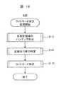
図18に示す本実施例の「ライトモード決定」処理は、実施例1の「ライトモード決定」を説明する、図11のS112「低速の判定」を、図18のS181「近接先行車の判定」に置換したものである。なお、図18のS111の処理、および、S113の処理は、実施例1の図11と同様であるので以下では重複説明は省略する。
図19は、S181の「近接先行車の判定」処理の詳細を示すフローチャートである。ここに示すように、まず、S191では、車間距離Dsが予め設定された近接車間距離(例えば15m)の範囲内であるかを判定し、該当しない場合は、ライトモード決定のための閾値を変更することなくS181の処理を終了する。また、車間距離Dsが予め設定された接近車間距離範囲内である場合、S192では、前回の判定周期に判定されたライトモードが「ライトOFF」であるかを判定し、該当しない場合(ライトモードが「ヘッドライトON」、「スモールライトON」の何れかの場合)は、ライトモード決定のための閾値を変更することなくS181の処理を終了する。
一方、S192で、前回の判定周期で判定されたライトモードが「ライトOFF」である場合には、S193にて、式8を用いて、判定閾値を再計算する。

ここで、式8のth_newは再計算した判定閾値、thは当初の判定閾値、Rは閾値の調整範囲、Dsは車間距離、Dfは予め設定された距離範囲(接近車判断処理のタイミング)、αは計算の調整変数である。
続いて、S194では、式9を用いて、先行車近接時の上部周囲環境光を再計算する。
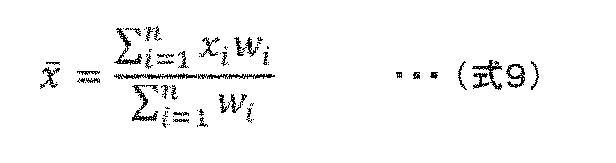
式9において、左辺は上部周囲環境光、右辺のxiは各測定領域の平均明るさ、wiは接近車による各測定領域の重み分布、nは設置の測定領域数である。
なお、本実施例では、各測定領域の重み分布wiを式10で定義する。

その後、S195では、S193で再計算された閾値と、S194で演算された上部周囲環境光を用いて、上部領域11のライトモードを選択し、S196では、図12と同様の手法によりハンチング防止処理を施した後、S181の処理を終了し、図18のライトモード決定処理(S113)に移行する。
実施例1の図14の処理などでは、単一のカメラを用い、車間距離を演算によって推測し、ライトモードを決定していたが、本実施例では、ステレオカメラを利用することで車間距離を正確に測定し、この正確な車間距離を踏まえて、ライトモードをより適切に設定できる。この結果、実施例1に比べても、ライトを不要に点灯させる状況を抑制でき、バッテリーの浪費を抑制できるとともに、運転者の感覚と一致したライト制御を行うことができる。
次に、本発明の実施例3のオートライトシステムについて説明する。なお、上述した実施例との共通点は重複説明を省略する。
図20は本実施例のオートライトシステムのブロック図である。実施例2では、ステレオカメラを用いて先行車との車間距離を測定し、それに応じた閾値を用いてライトモードを決定したが、本実施例ではレーダ測距部1Aを用いて、先行車との車間距離を測定し、それに応じた閾値を用いてライトモードを決定する。本実施例の処理ルーチンは、実施例2の図18、図19で説明したものと同様であるため、重複説明は省略する。
レーダ測距部1Aは、ミリ波レーダやLIDAR(Light Detection and Ranging)等の光照射とその反射光の受光による測距を行うものである。なお、本実施例の画像処理部2aは、図2に示した画像処理部2の構成に、レーダ測距部1Aとの接続のためのレーダ測距I/F27を付加したものである。
以上のように、レーダ測距部1Aを用いる本実施例の構成においても、実施例2と同様に、車間距離を正確に測定し、この正確な車間距離を踏まえて、ライトモードをより適切に設定できる。この結果、バッテリーの浪費を抑制できるとともに、運転者の感覚と一致したライト制御を行うことができる。
次に、本発明の実施例4のオートライトシステムについて説明する。本実施例は、ライトモードを決定する際に、地図情報と自社位置情報を用いる点で上述の実施例と相違する。なお、上述した実施例との共通点は重複説明を省略する。
図22は、本実施例のオートライトシステムのブロック図である。ここに示すように、本実施例のオートライトシステムは、実施例1の構成に地図連携部3aを付加したものであり、それに対応し、画像処理部2を画像処理部2bに置換したものである。
図23は、本実施例の画像処理部2bを示す機能ブロック図である。本実施例の画像処理部2bは、実施例1における画像処理部2とほぼ同等であるが、地図連携部3aと接続するための地図連携I/F28を備えている。
図24は、地図連携部3aの機能ブロック図である。ここに示すように、地図連携部3aには、演算装置241と、地図データベースやプログラムを記憶した主記憶装置242と、補助記憶装置243と、画像・表示I/F244と、図示しないGPS受信機からの測位信号を受信する測位I/F245と、撮像部1やレーダ測距1Aからの社外情報を受信するセンシングI/F246と、車両I/F247を備えている。
この地図連携部3aは、自車情報(速度等)やGPS衛星受信情報や他のセンシング情報(例えば、自車前方の画像データやレーダ測距等)を補助記憶装置243に転送して記憶させるとともに、そこに記憶した情報を基に自車位置・進行方向を推定する。また、演算装置241は、主記憶装置242に記憶されるプログラムを基に、所望のインターフェースに制御信号を送信する。演算装置241が推定した自車位置と進行方向は、地図情報とともに画像・表示I/F234に送信される。
そして、地図連携部3aでは、測位信号に基づいて自車位置を絶対座標として算出(測位)するとともに、車外情報に基づいて測位位置からの相対的な変化分として自車位置を算出する。さらに、地図データベースを用いて、算出された自車位置を地図の道路上の位置に補正するマップマッチング処理を行う。これらの処理の結果、地図連携部3aでは、道路上の自車推定位置と方向情報に基づいて、進行方向を高精度に推定できる。
画像処理部2bには、地図連携I/F28を介して、車両100の進行方向の道路形状や、トンネルの位置に加え、トンネル内の照明位置が入力されるため、これらを用いて、複数の上部測定領域の重みや、ライトモード判定のための閾値を事前に切り替えたり、トンネルなどの点灯が義務付けられる場所で、事前にヘッドライトを点灯しておくこともできるため、上述した実施例に比べ、ライトモードの切り替えを更に適切なものにすることができ、運転者の快適性を更に高めることができる。
なお、本発明は上記した実施例に限定されるものではなく、様々な変形例が含まれる。例えば、上記した実施例は本発明を分かりやすく説明するために詳細に説明したものであり、必ずしも説明した全ての構成を備えるものに限定されるものではない。また、ある実施例の構成の一部を他の実施例の構成に置き換えることが可能であり、また、ある実施例の構成に他の実施例の構成を加えることも可能である。また、各実施例の構成について、他の構成の追加、削除、置換をすることが可能である。
100 車両、
1 撮像部、
1a、1b カメラ、
1A レーダ測距部、
2、2a、2b 画像処理部、
3 車両情報取得部、
3a 地図連携部、
4 車両制御部、
5 照明切換部、
6 照明制御部、
7 照明部、
8 走行系制御部、
10、10a、10b 画像データ、
11 上部領域、
A0~A4 上部測定領域、
12 下部領域、
120 下部測定領域、
13 先行車、
21 演算装置
22 主記憶装置、
23 補助記憶装置、
24 撮像インターフェース、
25 照明制御インターフェース、
26 車両インターフェース、
27 レーダ測距インターフェース、
28 地図連携インターフェース、
171 計測対象物、
172a、172b 二次元センサー
1 撮像部、
1a、1b カメラ、
1A レーダ測距部、
2、2a、2b 画像処理部、
3 車両情報取得部、
3a 地図連携部、
4 車両制御部、
5 照明切換部、
6 照明制御部、
7 照明部、
8 走行系制御部、
10、10a、10b 画像データ、
11 上部領域、
A0~A4 上部測定領域、
12 下部領域、
120 下部測定領域、
13 先行車、
21 演算装置
22 主記憶装置、
23 補助記憶装置、
24 撮像インターフェース、
25 照明制御インターフェース、
26 車両インターフェース、
27 レーダ測距インターフェース、
28 地図連携インターフェース、
171 計測対象物、
172a、172b 二次元センサー
Claims (9)
- 周囲環境に応じて車両の照明を自動的に点灯または消灯するオートライトシステムであって、
前記車両の前方を撮像し画像データを生成する撮像装置と、
該画像データの上部領域と下部領域の明るさに基づいて前記照明の点灯又は消灯を制御するライトモード情報を生成する画像処理部と、
該ライトモード情報に基づいて前記照明を制御する照明制御部と、を備えており、
前記画像処理部は、前記上部領域に設定した複数の測定領域のうち、前記車両の進行方向の測定領域の重みを重く、他の測定領域の重みを軽くして、前記上部領域の明るさを演算し、該上部領域の明るさに基づいて前記ライトモード情報を生成することを特徴とするオートライトシステム。 - 前記画像処理部は、
演算した上部領域の明るさが第一の閾値より明るいときに、ライトOFFのライトモード情報を生成し、
演算した上部領域の明るさが第一の閾値より暗く第二の閾値より明るいときに、スモールライトONのライトモード情報を生成し、
演算した上部領域の明るさが第二の閾値より暗いときに、ヘッドライトONのライトモード情報を生成することを特徴とする請求項1に記載のオートライトシステム。 - 前記画像処理部は、
前記上部領域の平均色相を算出し、
演算した上部領域の明るさが第一の閾値より明るく、かつ、前記平均色相が基準範囲内にあるときに、ライトOFFのライトモード情報を生成し、
演算した上部領域の明るさが第一の閾値より明るく、かつ、前記平均色相が基準範囲外にあるときに、スモールライトONのライトモード情報を生成し、
演算した上部領域の明るさが第一の閾値より暗く第二の閾値より明るいときに、スモールライトONのライトモード情報を生成し、
演算した上部領域の明るさが第二の閾値より暗いときに、ヘッドライトONのライトモード情報を生成することを特徴とする請求項1に記載のオートライトシステム。 - 前記画像処理部は、
前記車両の車速が、停止、低速、減速中の何れかであり、かつ、
現状のライトモード情報がライトOFFであるときに、
前記第一の閾値または前記第二の閾値を小さくすることを特徴とする請求項2または請求項3に記載のオートライトシステム。 - 前記画像処理部は、
前記画像データに含まれる先行車の車体色が黒色または暗色であるときに、
前記第一の閾値または前記第二の閾値を小さくすることを特徴とする請求項2または請求項3に記載のオートライトシステム。 - さらに、先行車との車間距離を測定する車間距離測定装置を備えており、
前記画像処理部は、
前記車間距離が所定距離より小さいときに、
前記第一の閾値または前記第二の閾値を小さくすることを特徴とする請求項2または請求項3に記載のオートライトシステム。 - 前記車間距離測定装置は、
ステレオカメラ、または、レーダ測距装置であることを特徴とする請求項6に記載のオートライトシステム。 - さらに、地図データベースを内蔵した地図連携部を備えており、
前記画像処理部は、前記地図データベース内の道路情報を基に判定された前記車両の進行方向に応じて、各判定領域に対し重み付けを行うことを特徴とする請求項1に記載のオートライトシステム。 - 前記ライトモード情報の判定周期は、前記車両の車速が速ければ短くなる周期であることを特徴とする請求項1から請求項8の何れか一項に記載のオートライトシステム。
Priority Applications (4)
| Application Number | Priority Date | Filing Date | Title |
|---|---|---|---|
| DE112019000339.9T DE112019000339T5 (de) | 2018-03-14 | 2019-03-04 | Automatisches beleuchtungssystem |
| CN201980013701.XA CN111727135B (zh) | 2018-03-14 | 2019-03-04 | 自动照明系统 |
| JP2020506406A JP6924325B2 (ja) | 2018-03-14 | 2019-03-04 | オートライトシステム |
| US16/976,613 US11325522B2 (en) | 2018-03-14 | 2019-03-04 | Automatic light system |
Applications Claiming Priority (2)
| Application Number | Priority Date | Filing Date | Title |
|---|---|---|---|
| JP2018046236 | 2018-03-14 | ||
| JP2018-046236 | 2018-03-14 |
Publications (1)
| Publication Number | Publication Date |
|---|---|
| WO2019176604A1 true WO2019176604A1 (ja) | 2019-09-19 |
Family
ID=67906978
Family Applications (1)
| Application Number | Title | Priority Date | Filing Date |
|---|---|---|---|
| PCT/JP2019/008272 Ceased WO2019176604A1 (ja) | 2018-03-14 | 2019-03-04 | オートライトシステム |
Country Status (5)
| Country | Link |
|---|---|
| US (1) | US11325522B2 (ja) |
| JP (1) | JP6924325B2 (ja) |
| CN (1) | CN111727135B (ja) |
| DE (1) | DE112019000339T5 (ja) |
| WO (1) | WO2019176604A1 (ja) |
Cited By (4)
| Publication number | Priority date | Publication date | Assignee | Title |
|---|---|---|---|---|
| CN112154715A (zh) * | 2019-09-24 | 2020-12-29 | 深圳市大疆创新科技有限公司 | 智能辅助照明系统、方法、装置及可移动平台 |
| JP2021133823A (ja) * | 2020-02-27 | 2021-09-13 | 株式会社小糸製作所 | 車両用前照灯 |
| CN114572102A (zh) * | 2022-01-28 | 2022-06-03 | 上海康耐司信号设备有限公司 | 一种适用于车灯的智能调节系统及方法 |
| JP2024131362A (ja) * | 2023-03-16 | 2024-09-30 | トヨタ自動車株式会社 | 赤外線投光制御装置、赤外線投光制御方法及び赤外線投光制御プログラム |
Families Citing this family (10)
| Publication number | Priority date | Publication date | Assignee | Title |
|---|---|---|---|---|
| US11560083B2 (en) * | 2020-08-20 | 2023-01-24 | Pony Ai Inc. | Autonomous headlamp encapsulated with camera and artificial intelligence processor to adjust illumination |
| CN113212292A (zh) * | 2021-05-13 | 2021-08-06 | 蔚来汽车科技(安徽)有限公司 | 车辆的控制方法及装置、车载设备、车辆、介质 |
| CN113438765B (zh) * | 2021-06-25 | 2022-08-05 | 深圳市皓丽软件有限公司 | 一种平衡感应灯及其灯光控制方法、存储介质 |
| CN113739090B (zh) * | 2021-08-20 | 2023-06-30 | 扬州市职业大学(扬州市广播电视大学) | 一种自动化照明装置 |
| CN114771398A (zh) * | 2022-03-22 | 2022-07-22 | 合众新能源汽车有限公司 | 车灯控制方法、系统、装置和计算机可读介质 |
| DE102022120937A1 (de) | 2022-08-18 | 2024-02-29 | Bayerische Motoren Werke Aktiengesellschaft | Verfahren zu einer helligkeitsabhängigen Steuerung einer visuellen Inszenierung eines Fahrzeugs für dessen Nutzer |
| JP2024125880A (ja) * | 2023-03-06 | 2024-09-19 | ラピステクノロジー株式会社 | 暗所判定装置、暗所判定方法、及び暗所判定プログラム |
| DE102023203280A1 (de) | 2023-04-11 | 2024-10-17 | Robert Bosch Gesellschaft mit beschränkter Haftung | Verfahren und Vorrichtung zur Steuerung eines Lichtassistenten eines Kraftfahrzeugs |
| CN117656986B (zh) * | 2024-01-31 | 2024-04-16 | 成都赛力斯科技有限公司 | 一种基于障碍物的车灯控制方法、装置、设备及存储介质 |
| CN119255442B (zh) * | 2024-07-30 | 2025-09-30 | 云南华尔贝光电技术有限公司 | 一种照明用具的自动控制方法、装置、设备及存储介质 |
Citations (6)
| Publication number | Priority date | Publication date | Assignee | Title |
|---|---|---|---|---|
| JP2005075304A (ja) * | 2003-09-03 | 2005-03-24 | Denso Corp | 車両用ライト点灯制御装置 |
| JP2008110715A (ja) * | 2006-10-31 | 2008-05-15 | Mitsubishi Electric Corp | 車両用オートライトシステム |
| JP2009255722A (ja) * | 2008-04-16 | 2009-11-05 | Denso Corp | 走行環境検出方法および車両用灯火制御装置 |
| JP2010006172A (ja) * | 2008-06-25 | 2010-01-14 | Hitachi Ltd | オートライト装置 |
| WO2012066609A1 (ja) * | 2010-11-19 | 2012-05-24 | 三菱電機株式会社 | 環境推定装置及び車両制御装置 |
| JP2015071403A (ja) * | 2013-09-04 | 2015-04-16 | 株式会社デンソー | 光センサ |
Family Cites Families (7)
| Publication number | Priority date | Publication date | Assignee | Title |
|---|---|---|---|---|
| US7482756B2 (en) * | 2003-10-21 | 2009-01-27 | Raymond Kesterson | Directional lamp daytime running light module and vehicular turn signal control system |
| TWM270954U (en) * | 2004-10-26 | 2005-07-21 | Yung-Cheng Chen | Light-sensitive lamp-controlling structure of scooter |
| JP4798125B2 (ja) * | 2007-12-13 | 2011-10-19 | 株式会社デンソー | 照度センサ |
| JP5481074B2 (ja) * | 2009-01-23 | 2014-04-23 | 株式会社豊田中央研究所 | 照明環境判定装置及びプログラム |
| JP5251680B2 (ja) * | 2009-03-31 | 2013-07-31 | 株式会社豊田中央研究所 | 照明制御装置及びプログラム |
| JP5197484B2 (ja) * | 2009-05-21 | 2013-05-15 | ナイルス株式会社 | 車両用ライト制御装置 |
| JP6680095B2 (ja) * | 2016-06-10 | 2020-04-15 | スズキ株式会社 | ポジション照明装置 |
-
2019
- 2019-03-04 CN CN201980013701.XA patent/CN111727135B/zh active Active
- 2019-03-04 JP JP2020506406A patent/JP6924325B2/ja active Active
- 2019-03-04 WO PCT/JP2019/008272 patent/WO2019176604A1/ja not_active Ceased
- 2019-03-04 US US16/976,613 patent/US11325522B2/en active Active
- 2019-03-04 DE DE112019000339.9T patent/DE112019000339T5/de active Pending
Patent Citations (6)
| Publication number | Priority date | Publication date | Assignee | Title |
|---|---|---|---|---|
| JP2005075304A (ja) * | 2003-09-03 | 2005-03-24 | Denso Corp | 車両用ライト点灯制御装置 |
| JP2008110715A (ja) * | 2006-10-31 | 2008-05-15 | Mitsubishi Electric Corp | 車両用オートライトシステム |
| JP2009255722A (ja) * | 2008-04-16 | 2009-11-05 | Denso Corp | 走行環境検出方法および車両用灯火制御装置 |
| JP2010006172A (ja) * | 2008-06-25 | 2010-01-14 | Hitachi Ltd | オートライト装置 |
| WO2012066609A1 (ja) * | 2010-11-19 | 2012-05-24 | 三菱電機株式会社 | 環境推定装置及び車両制御装置 |
| JP2015071403A (ja) * | 2013-09-04 | 2015-04-16 | 株式会社デンソー | 光センサ |
Cited By (7)
| Publication number | Priority date | Publication date | Assignee | Title |
|---|---|---|---|---|
| CN112154715A (zh) * | 2019-09-24 | 2020-12-29 | 深圳市大疆创新科技有限公司 | 智能辅助照明系统、方法、装置及可移动平台 |
| CN112154715B (zh) * | 2019-09-24 | 2024-01-26 | 深圳市大疆创新科技有限公司 | 智能辅助照明系统、方法、装置及可移动平台 |
| JP2021133823A (ja) * | 2020-02-27 | 2021-09-13 | 株式会社小糸製作所 | 車両用前照灯 |
| JP7458820B2 (ja) | 2020-02-27 | 2024-04-01 | 株式会社小糸製作所 | 車両用前照灯 |
| CN114572102A (zh) * | 2022-01-28 | 2022-06-03 | 上海康耐司信号设备有限公司 | 一种适用于车灯的智能调节系统及方法 |
| CN114572102B (zh) * | 2022-01-28 | 2023-07-14 | 上海康耐司信号设备有限公司 | 一种适用于车灯的智能调节系统及方法 |
| JP2024131362A (ja) * | 2023-03-16 | 2024-09-30 | トヨタ自動車株式会社 | 赤外線投光制御装置、赤外線投光制御方法及び赤外線投光制御プログラム |
Also Published As
| Publication number | Publication date |
|---|---|
| JPWO2019176604A1 (ja) | 2020-12-03 |
| DE112019000339T5 (de) | 2020-09-17 |
| CN111727135B (zh) | 2023-04-07 |
| CN111727135A (zh) | 2020-09-29 |
| JP6924325B2 (ja) | 2021-08-25 |
| US20210001767A1 (en) | 2021-01-07 |
| US11325522B2 (en) | 2022-05-10 |
Similar Documents
| Publication | Publication Date | Title |
|---|---|---|
| JP6924325B2 (ja) | オートライトシステム | |
| CN104210421B (zh) | 周围环境判定装置 | |
| JP6310899B2 (ja) | 車外環境認識装置 | |
| US10442343B2 (en) | Vehicle exterior environment recognition apparatus | |
| JP5409929B2 (ja) | 車両用ヘッドライト装置の制御方法およびヘッドライト装置 | |
| JP5097648B2 (ja) | 前照灯制御装置および車両用前照灯装置 | |
| US9827956B2 (en) | Method and device for detecting a braking situation | |
| US9527429B2 (en) | Method and device for controlling a light emission of at least one headlight of a vehicle | |
| EP2537709A2 (en) | Image processing apparatus and light distribution control method | |
| US9404630B2 (en) | Method and device for operating a headlamp for a motor vehicle | |
| CN105835753A (zh) | 用于调节车辆的驾驶员辅助设备的至少一个参数的方法和控制设备 | |
| JP2014231301A (ja) | 画像処理装置 | |
| JP6151569B2 (ja) | 周囲環境判定装置 | |
| JP2023506519A (ja) | 自動車両の照明システムを制御するための方法 | |
| JP7378673B2 (ja) | 前照灯制御装置、前照灯制御システム、及び前照灯制御方法 | |
| JP5873372B2 (ja) | ヘッドライトの配光制御装置 | |
| JP2006146754A (ja) | 先行車検出方法及び先行車検出装置 | |
| JP6539191B2 (ja) | 車外環境認識装置 | |
| JP6549974B2 (ja) | 車外環境認識装置 | |
| JP5859897B2 (ja) | 車載カメラ装置 | |
| KR102962206B1 (ko) | 차량의 이벤트 기반 센서를 이용한 지능형 프론트 라이팅 시스템 | |
| JP6549973B2 (ja) | 車外環境認識装置 | |
| KR20260007756A (ko) | 램프 제어 시스템, 램프 제어 방법 및 차량 | |
| JP2013086739A (ja) | ヘッドライト制御装置、ヘッドライトシステム、及びヘッドライトシステムの制御方法 |
Legal Events
| Date | Code | Title | Description |
|---|---|---|---|
| 121 | Ep: the epo has been informed by wipo that ep was designated in this application |
Ref document number: 19767401 Country of ref document: EP Kind code of ref document: A1 |
|
| ENP | Entry into the national phase |
Ref document number: 2020506406 Country of ref document: JP Kind code of ref document: A |
|
| 122 | Ep: pct application non-entry in european phase |
Ref document number: 19767401 Country of ref document: EP Kind code of ref document: A1 |