WO2019176600A1 - 放電灯を含む光源装置、照射装置、および放電灯の判定方法 - Google Patents
放電灯を含む光源装置、照射装置、および放電灯の判定方法 Download PDFInfo
- Publication number
- WO2019176600A1 WO2019176600A1 PCT/JP2019/008241 JP2019008241W WO2019176600A1 WO 2019176600 A1 WO2019176600 A1 WO 2019176600A1 JP 2019008241 W JP2019008241 W JP 2019008241W WO 2019176600 A1 WO2019176600 A1 WO 2019176600A1
- Authority
- WO
- WIPO (PCT)
- Prior art keywords
- discharge lamp
- light source
- ultraviolet light
- switch
- turned
- Prior art date
Links
Images


Classifications
-
- G—PHYSICS
- G01—MEASURING; TESTING
- G01R—MEASURING ELECTRIC VARIABLES; MEASURING MAGNETIC VARIABLES
- G01R31/00—Arrangements for testing electric properties; Arrangements for locating electric faults; Arrangements for electrical testing characterised by what is being tested not provided for elsewhere
- G01R31/24—Testing of discharge tubes
- G01R31/245—Testing of gas discharge tubes
-
- H—ELECTRICITY
- H01—ELECTRIC ELEMENTS
- H01J—ELECTRIC DISCHARGE TUBES OR DISCHARGE LAMPS
- H01J61/00—Gas-discharge or vapour-discharge lamps
- H01J61/82—Lamps with high-pressure unconstricted discharge having a cold pressure > 400 Torr
- H01J61/822—High-pressure mercury lamps
-
- G—PHYSICS
- G03—PHOTOGRAPHY; CINEMATOGRAPHY; ANALOGOUS TECHNIQUES USING WAVES OTHER THAN OPTICAL WAVES; ELECTROGRAPHY; HOLOGRAPHY
- G03F—PHOTOMECHANICAL PRODUCTION OF TEXTURED OR PATTERNED SURFACES, e.g. FOR PRINTING, FOR PROCESSING OF SEMICONDUCTOR DEVICES; MATERIALS THEREFOR; ORIGINALS THEREFOR; APPARATUS SPECIALLY ADAPTED THEREFOR
- G03F7/00—Photomechanical, e.g. photolithographic, production of textured or patterned surfaces, e.g. printing surfaces; Materials therefor, e.g. comprising photoresists; Apparatus specially adapted therefor
- G03F7/20—Exposure; Apparatus therefor
- G03F7/2002—Exposure; Apparatus therefor with visible light or UV light, through an original having an opaque pattern on a transparent support, e.g. film printing, projection printing; by reflection of visible or UV light from an original such as a printed image
- G03F7/2004—Exposure; Apparatus therefor with visible light or UV light, through an original having an opaque pattern on a transparent support, e.g. film printing, projection printing; by reflection of visible or UV light from an original such as a printed image characterised by the use of a particular light source, e.g. fluorescent lamps or deep UV light
-
- G—PHYSICS
- G03—PHOTOGRAPHY; CINEMATOGRAPHY; ANALOGOUS TECHNIQUES USING WAVES OTHER THAN OPTICAL WAVES; ELECTROGRAPHY; HOLOGRAPHY
- G03F—PHOTOMECHANICAL PRODUCTION OF TEXTURED OR PATTERNED SURFACES, e.g. FOR PRINTING, FOR PROCESSING OF SEMICONDUCTOR DEVICES; MATERIALS THEREFOR; ORIGINALS THEREFOR; APPARATUS SPECIALLY ADAPTED THEREFOR
- G03F7/00—Photomechanical, e.g. photolithographic, production of textured or patterned surfaces, e.g. printing surfaces; Materials therefor, e.g. comprising photoresists; Apparatus specially adapted therefor
- G03F7/20—Exposure; Apparatus therefor
- G03F7/2002—Exposure; Apparatus therefor with visible light or UV light, through an original having an opaque pattern on a transparent support, e.g. film printing, projection printing; by reflection of visible or UV light from an original such as a printed image
- G03F7/2008—Exposure; Apparatus therefor with visible light or UV light, through an original having an opaque pattern on a transparent support, e.g. film printing, projection printing; by reflection of visible or UV light from an original such as a printed image characterised by the reflectors, diffusers, light or heat filtering means or anti-reflective means used
-
- H—ELECTRICITY
- H01—ELECTRIC ELEMENTS
- H01J—ELECTRIC DISCHARGE TUBES OR DISCHARGE LAMPS
- H01J61/00—Gas-discharge or vapour-discharge lamps
- H01J61/02—Details
- H01J61/54—Igniting arrangements, e.g. promoting ionisation for starting
- H01J61/548—Igniting arrangements, e.g. promoting ionisation for starting using radioactive means to promote ionisation
-
- H—ELECTRICITY
- H05—ELECTRIC TECHNIQUES NOT OTHERWISE PROVIDED FOR
- H05B—ELECTRIC HEATING; ELECTRIC LIGHT SOURCES NOT OTHERWISE PROVIDED FOR; CIRCUIT ARRANGEMENTS FOR ELECTRIC LIGHT SOURCES, IN GENERAL
- H05B35/00—Electric light sources using a combination of different types of light generation
-
- H—ELECTRICITY
- H05—ELECTRIC TECHNIQUES NOT OTHERWISE PROVIDED FOR
- H05K—PRINTED CIRCUITS; CASINGS OR CONSTRUCTIONAL DETAILS OF ELECTRIC APPARATUS; MANUFACTURE OF ASSEMBLAGES OF ELECTRICAL COMPONENTS
- H05K3/00—Apparatus or processes for manufacturing printed circuits
- H05K3/02—Apparatus or processes for manufacturing printed circuits in which the conductive material is applied to the surface of the insulating support and is thereafter removed from such areas of the surface which are not intended for current conducting or shielding
- H05K3/027—Apparatus or processes for manufacturing printed circuits in which the conductive material is applied to the surface of the insulating support and is thereafter removed from such areas of the surface which are not intended for current conducting or shielding the conductive material being removed by irradiation, e.g. by photons, alpha or beta particles
-
- H—ELECTRICITY
- H05—ELECTRIC TECHNIQUES NOT OTHERWISE PROVIDED FOR
- H05B—ELECTRIC HEATING; ELECTRIC LIGHT SOURCES NOT OTHERWISE PROVIDED FOR; CIRCUIT ARRANGEMENTS FOR ELECTRIC LIGHT SOURCES, IN GENERAL
- H05B41/00—Circuit arrangements or apparatus for igniting or operating discharge lamps
- H05B41/02—Details
- H05B41/04—Starting switches
-
- H—ELECTRICITY
- H05—ELECTRIC TECHNIQUES NOT OTHERWISE PROVIDED FOR
- H05B—ELECTRIC HEATING; ELECTRIC LIGHT SOURCES NOT OTHERWISE PROVIDED FOR; CIRCUIT ARRANGEMENTS FOR ELECTRIC LIGHT SOURCES, IN GENERAL
- H05B45/00—Circuit arrangements for operating light-emitting diodes [LED]
Definitions
- the present invention relates to a light source device including a discharge lamp that emits light used for exposure of a printed wiring board or the like, an irradiation device, and a method for determining whether or not the discharge lamp is a genuine product.
- a printed wiring board in which a wiring pattern is formed of a metal such as copper on a substrate made of resin or glass epoxy material has been used to mount components on an electronic device.
- Photo-etching technology is used to form wiring patterns on these printed wiring boards. Photo-etching is performed by applying a photoresist, which is a photosensitive chemical, to the entire surface of the substrate on which the metal layer that will be the wiring is formed, and irradiating light from the exposure device through the same photomask as the wiring pattern.
- photoresists There are two types of photoresists: a negative type photoresist whose solubility is reduced by irradiation light and a positive type photoresist whose solubility is increased by irradiation light.
- the photoresist portion whose solubility has been relatively increased by irradiation light is removed by chemical treatment, and when the exposed metal layer is removed by etching, only the metal layer under the portion where the photoresist remains is left, and the photoresist is removed.
- a wiring pattern is formed on the substrate.
- a discharge lamp with a large light emission amount per lamp is used as a light source in order to ensure a uniform exposure amount over the entire irradiation surface. ing.
- a discharge lamp generates an arc discharge between a pair of electrodes that are spaced apart from each other in an airtight inner space of an arc tube, thereby exciting mercury enclosed in the inner space to emit ultraviolet light. Is made to emit light.
- a glow discharge is started between a pair of electrodes, and then the arc discharge is started.
- a vacuum environment is used. Therefore, it is necessary to cause dielectric breakdown between electrodes that are physically separated. In order to cause this dielectric breakdown, it is necessary to apply a high-frequency high voltage between the electrodes.
- a power supply device that applies such a high voltage is very expensive, and the generated high-frequency voltage is around the surroundings. The possibility of inducing machine malfunctions has also been pointed out. For this reason, various ideas have been proposed in order to start discharge at a low voltage or low frequency, that is, to improve the startability of the discharge lamp.
- Patent Document 1 describes a technique for improving startability by enclosing a startability promoting substance such as krypton 85 in the inner space of the arc tube.
- the present invention has been made in view of the above-mentioned problems, and its purpose is to obtain good startability without enclosing a startability promoting substance in the inner space of the arc tube in the discharge lamp, and Another object of the present invention is to provide a light source device, an irradiating device, and a method for determining whether or not the discharge lamp is a genuine product.
- a discharge lamp as a light source An irradiation apparatus is provided that includes an ultraviolet light source that irradiates the discharge lamp with ultraviolet light in order to detect whether the discharge lamp is a genuine product when the discharge lamp is started.
- the irradiation device includes a plurality of the discharge lamps, and the ultraviolet light source irradiates the plurality of discharge lamps with the ultraviolet light.
- the ultraviolet light source is attached in the vicinity of the discharge lamp, and one ultraviolet light source irradiates the ultraviolet light to one discharge lamp.
- the ultraviolet light source is an LED.
- the irradiation device comprises: A discharge lamp power supply for supplying lighting power to the discharge lamp; A power source for an ultraviolet light source that supplies power for lighting to the ultraviolet light source; A discharge lamp switch for turning on and off the power from the discharge lamp power supply; An ultraviolet light source switch for turning on and off the power from the ultraviolet light source; The discharge lamp switch and the ultraviolet light source switch have a function of turning on and off. The first time, the discharge lamp switch is turned on while the ultraviolet light source switch is turned off.
- the power for turning on the discharge lamp supplied from the power supply for the discharge lamp is turned off with the switch for turning on and off the power for turning on the ultraviolet light source supplied from the power supply for the ultraviolet light source turned off.
- Second time with the ultraviolet light source switch turned on, turn on the discharge lamp switch,
- the discharge lamp switch is turned on the second time. Only when the discharge lamp is lit, it is determined that the discharge lamp is a genuine product.
- FIG. 10 is a cross-sectional view illustrating an example of a light source device 100 according to Modification 3.
- FIG. 1 shows an exposure apparatus 10 according to a first embodiment to which the present invention is applied.
- the exposure machine 10 is generally composed of an irradiation device 50, an integrator 12, a concave mirror 14, and an irradiation surface 16.
- the irradiation device 50 emits light including a wavelength suitable for exposure of the exposure object X.
- the details of the irradiation apparatus 50 will be described after the configuration of the exposure apparatus 10 is described.
- the concave mirror 14 has a reflective concave surface 22 inside thereof.
- the concave mirror 14 reflects the light emitted from the integrator 12 by the reflecting concave surface 22 to make parallel light.
- FIG. 2 is a diagram showing an irradiation apparatus 50 according to the first embodiment to which the present invention is applied.
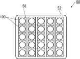
- FIG. 3 is a plan view of the irradiation device 50.
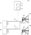
- the irradiation device 50 includes a plurality of light source devices 100, an ultraviolet light source 200, a frame 52, a discharge lamp switch 53, a discharge lamp power source 54, an ultraviolet light source switch 55, and an ultraviolet light source power source 56.
- Device 57 is a plurality of light source devices 100, an ultraviolet light source 200, a frame 52, a discharge lamp switch 53, a discharge lamp power source 54, an ultraviolet light source switch 55, and an ultraviolet light source power source 56.
- the ultraviolet light source 200 is an LED that emits ultraviolet light, and is incorporated in each light source device 100. Therefore, the description of the ultraviolet light source 200 in this embodiment will be made together with the description of the light source device 100.
- the ultraviolet light source 200 is not limited to an LED, and a high-pressure mercury lamp, a metal halide lamp, or the like may be used as long as it can emit ultraviolet light.
- a high-pressure mercury lamp, a metal halide lamp, or the like may be used as long as it can emit ultraviolet light.
- Modification 1 described later when irradiating a plurality of discharge lamps 110 with ultraviolet light, it is preferable to select a lamp with a large amount of light emission per unit.
- the discharge lamp 110 has an arc tube portion 112 and a pair of seal portions 114 extending from the arc tube portion 112.
- the arc tube portion 112 and the pair of seal portions 114 are integrally formed of quartz glass. Furthermore, an inner space 116 sealed by a seal portion 114 is formed in the arc tube portion 112.
- each seal portion 114 of the discharge lamp 110 an embedded molybdenum foil 118 and one end made of tungsten having one end connected to one end of the foil 118 and the other end disposed in the internal space 116.
- a pair of electrodes 120 and a pair of lead rods 122 each having one end connected to the other end of the foil 118 and the other end extending from the seal portion 114 to the outside are provided.
- the internal space 116 is filled with a predetermined amount of mercury 124 and halogen (for example, bromine).
- one seal portion 114 is inserted into the seal portion insertion hole 156 of the reflector 150.
- the discharge lamp 110 may be for AC lighting or DC lighting.
- the reflector 150 has a bowl-shaped reflecting surface 152 on its inner surface.
- the reflecting surface 152 reflects a part of the light from the discharge lamp 110 arranged so that the arc tube portion 112 is located inside the reflector 150.
- the reflecting surface 152 is defined by a rotating paraboloid.
- the light emitting point generally, the center position of the arc formed between the pair of electrodes 120 in the internal space 116 in the discharge lamp 110 coincides with the focal point of the rotating paraboloid. Thereby, the light emitted from the light emitting point of the discharge lamp 110 and reflected by the reflecting surface 152 and then exiting the opening 154 of the reflector 150 becomes substantially parallel light.
- the shape of the reflecting surface 152 is not limited to this, and may be a spheroidal surface, another rotating surface, or a shape other than the rotating surface. Further, it is not essential to make the light emitting point coincide with the focal point, and the light emitting point may be shifted from the focal point as necessary.
- the light emitted from the discharge lamp 110 has a predetermined angle (opening angle) centered on the light traveling along the central axis CL of the reflecting surface 152. It will come ahead of the reflector 150 in the range with.
- the insulating base 170 is formed of an electrical insulator such as ceramic, and one seal portion in the discharge lamp 110 inserted in the bottom neck portion 155 and the seal portion insertion hole 156 of the reflector 150.
- a reflector insertion hole 172 into which 114 is inserted is formed.
- the insulating base 170 is formed with an inner space 174 communicating with the reflector insertion hole 172 described above, and further, a power cable insertion hole through which the power cable A is inserted by communicating the inner space 174 with the outer side. 176 is formed.
- the insulating base 170 and the discharge lamp 110 are fixed to each other by an inorganic adhesive C having electrical insulation and high thermal conductivity. More specifically, the end of the bottom neck portion 155 of the reflector 150 and one seal portion 114 of the discharge lamp 110 are inserted into the reflector insertion hole 172 of the insulating base 170, and the inner space 174 of the insulating base 170 is further inserted. In the state where the ultraviolet light source 200 and the power cable A are arranged, the inner space 174 is filled with the inorganic adhesive C.
- the ultraviolet light source 200 is attached in the vicinity of the discharge lamp 110, and more specifically, the end surface of the seal portion 114 on the side where the ultraviolet light from the ultraviolet light source 200 is inserted into the reflector insertion hole 172 in the discharge lamp 110. It is preferable to provide it at a position where it is emitted toward
- the frame 52 is a substantially rectangular parallelepiped member having a plurality of recesses 58 in which the plurality of light source devices 100 are mounted.
- the discharge lamp power supply 54 supplies necessary electric power (direct current or alternating current) to the discharge lamp 110 of each light source device 100 attached to the frame 52.
- the ultraviolet light source power source 56 is a power source that supplies a direct current to the ultraviolet light source 200 incorporated in each light source device 100, and the ultraviolet light source switch 55 turns on a constant DC current supplied to the ultraviolet light source 200. Turn off.
- the direct current supplied by the ultraviolet light source power supply 56 flows in the forward direction of the LEDs constituting the ultraviolet light source 200.
- the control unit 60 operates the discharge lamp switch 53 and the ultraviolet light source switch 55 to turn on / off the current supplied from the discharge lamp power supply 54 to the discharge lamp 110 and from the ultraviolet light source power supply 56 to the ultraviolet light source.
- 200 has a function of turning on and off the current supplied to the circuit 200.
- the control unit 60 basically performs two operations. That is, the control unit 60 turns on the discharge lamp switch 53 with the ultraviolet light source switch 55 turned off for the first time, and turns on the ultraviolet light source switch 55 for the second time. 53 is turned on.
- the determination unit 66 determines whether or not the discharge lamp 110 is lit in the first and second operations, and determines whether or not the discharge lamp 110 is a genuine product based on the determination result as described above. judge.
- the control unit 60 After the genuine product determination in the first light source device 100 is completed, the control unit 60 starts supplying current to the discharge lamp 110 in the other light source device 100. Thereafter, the genuine product determination is performed in the same manner as in the case of the first light source device 100 described above, and the same is performed until the determination of all the light source devices 100 is completed or the inspection of the light source devices 100 in a predetermined range is completed. Repeat the determination.
- the determination device 57 was able to determine whether or not the discharge lamp 110 was a genuine product. Thereby, it is possible to avoid erroneous use of the non-genuine discharge lamp 110 that is used for a long period of time and has a risk of explosion.
- the ultraviolet light source (LED) 200 is attached to each of the plurality of discharge lamps 110.
- the discharge lamp 110 in the plurality of light source devices 100 attached to the frame 52 is provided.
- One ultraviolet light source 200 may be arranged so that ultraviolet light can be irradiated toward the surface.
- the ultraviolet light from the ultraviolet light source 200 directly irradiates the arc tube portion 112 of the discharge lamp 110 through the opening 154 of each reflector 150 in the light source device 100.
- the number of ultraviolet light sources 200 to be arranged may be plural.
- the method for determining whether or not the discharge lamp 110 is a genuine product is the same as in the first embodiment.
- the discharge lamp switch 53 that supplies power to the discharge lamp 110 to be determined is turned on and the discharge lamp 110 lights up. Check whether or not.
- the discharge lamp switch 53 is turned on to check whether the discharge lamp 110 is lit.
- the discharge lamp 110 is turned on when both the discharge lamp switch 53 is turned on as a result of the first operation and the second operation, it is determined that the discharge lamp 110 is not a genuine product. If the discharge lamp 110 is turned on only when the discharge lamp switch 53 is turned on for the second time (that is, when the ultraviolet light source switch 55 is turned on), it is determined that the discharge lamp 110 is a genuine product. To do.
- the ultraviolet light source 200 of the light source device 100 in the above-described embodiment is composed of only LEDs, as shown in FIG. 8, the ultraviolet light source 200 is connected to the LED 202 and the incandescent lamp connected in series to the LED 202. 204, and may be provided in the light source device 100 (more precisely, in the inner space 174 of the insulating base 170 as in the first embodiment). Note that a fuse may be attached in series with the LED 202 or the incandescent lamp 204 for circuit protection or the like.
- the genuine product determination of the light source device 100 can be combined with the method using the ultraviolet light source 200 and the method using the incandescent lamp 204 as in the first embodiment described above. Both methods may be performed simultaneously, or either one may be performed.
- the both-ends voltage of the ultraviolet light source 200 is measured by a measurement unit (not shown; the same applies hereinafter) of the determination device 57 (first time).
- the measurement unit again measures the voltage across the ultraviolet light source 200 (second time).
- the measured voltage values at both ends are sent to the determination unit 66 of the determination device 57.
- the constant current flowing through the ultraviolet light source 200 is a direct current corresponding to the forward current of the LED 202.
- the determination unit 66 that has received the two voltage values at both ends checks whether or not the difference between the two voltage values at the two times is within a predetermined voltage range, and the difference between the two voltage values is within the predetermined voltage range. In this case, the determination unit 66 determines that the discharge lamp 110 to be inspected is a genuine product. Conversely, when the difference between the voltage values at both ends is not within the predetermined voltage range, the determination unit 66 determines that the discharge lamp 110 to be inspected is not a genuine product.
- the incandescent lamp 204 tends to increase in resistance value for a while (ten seconds) due to the characteristics of the filament contained therein. For this reason, the voltage value (for example, 8.5 V) of the ultraviolet light source 200 measured for the second time is larger than the value (for example, 2.0 V) of the same voltage measured for the first time. As a result, if the difference between the voltage values at both ends of the two measurements described above is within a predetermined voltage range (for example, between 6 and 7 V), it is determined that the discharge lamp 110 is a genuine product including the incandescent lamp 204. can do.
- a predetermined voltage range for example, between 6 and 7 V
- the ultraviolet light source 200 does not include the incandescent lamp 204. Therefore, the difference between the first measured value and the second measured value in the voltage value across the ultraviolet light source 200 is as follows. Nearly zero. Therefore, when the difference between the voltage values at both ends is not within the predetermined voltage range, the determination unit 66 determines that the discharge lamp 110 to be inspected is not a genuine product.
- the ultraviolet light source 200 that irradiates the ultraviolet light toward the discharge lamp 110 in the plurality of light source devices 100 attached to the frame 52 as in the first modification described above, not the LED 202 as shown in FIG. Only the incandescent lamp 204 may be provided in the light source device 100.
- the incandescent lamp 204 may be disposed in any of the insulating bases 170, or may be attached to the reflector container 151 by being disposed on the outer surface of the insulating base 170, the outer surface of the reflector 150, or the like. Also, a fuse may be attached in series with the incandescent lamp 204 for circuit protection or the like.
- the genuine product determination of the light source device 100 can combine the method using the ultraviolet light source 200 and the method using the incandescent lamp 204 as in the first modification. Both methods may be performed simultaneously, in sequence, or either one may be performed.
- the controller 60 continues to supply a constant current (either AC or DC) to the incandescent lamp 204 from the ultraviolet light source 56 or another power source (not shown). In this state, the measurement is performed by measuring the voltage across the pair of power cables A connected to the incandescent lamp 204 twice with a predetermined time (for example, 10 seconds).
- the voltage at both ends of the incandescent lamp 204 is measured by a measuring unit (not shown; the same applies hereinafter) of the determination device 57 (first time).
- the measurement unit again measures the voltage across the incandescent lamp 204 (second time). The measured voltage values at both ends are sent to the determination unit 66 of the determination device 57.
- the determination unit 66 that has received the two voltage values at both ends checks whether or not the difference between the two voltage values at the two times is within a predetermined voltage range, and the difference between the two voltage values is within the predetermined voltage range. In this case, the determination unit 66 determines that the discharge lamp 110 to be inspected is a genuine product. Conversely, when the difference between the voltage values at both ends is not within the predetermined voltage range, the determination unit 66 determines that the discharge lamp 110 to be inspected is not a genuine product.
- the discharge lamp 110 is a genuine product provided with the incandescent lamp 204
- the voltage value at the both ends of the incandescent lamp 204 is larger at the second measured value than at the first measured value.
- the reason for this is the same as that described in the second modification, and is omitted here.
- the discharge lamp 110 is a genuine product including the incandescent lamp 204. Can be determined.
- the determination unit 66 determines that the discharge lamp 110 to be inspected is not a genuine product.
Abstract
放電灯における発光管の内部空間に始動性促進物質を封入しなくても良好な始動性を得ることができ、かつ、その放電灯が純正品か否かを見分けることのできる照射装置を提供する。 照射装置(50)を、光源となる放電灯(110)と、放電灯(110)の始動時において、放電灯(110)が純正品であるかどうかを検出するために放電灯(110)に対して紫外光を照射する紫外線光源(200)とで構成する。
Description
本発明は、例えば、プリント配線基板等の露光に用いる光を発する放電灯を含む光源装置、照射装置、および当該放電灯が純正品であるか否かの判定方法に関する。
従来、電子機器に部品を実装するために樹脂やガラスエポキシ材の基板上に銅等の金属で配線パターンを形成したプリント配線基板が用いられている。これらのプリント配線基板上への配線パターンの形成にはフォトエッチング技術が用いられている。フォトエッチングは、配線となる金属層が全面に形成された基板上全面に、感光性の薬剤であるフォトレジストを塗布し、これに配線パターンと同一のフォトマスクを通して露光装置からの照射光を照射することによって行う。
フォトレジストには、照射光によりフォトレジストの溶解性が低下するネガ型フォトレジストと、逆に照射光によりフォトレジストの溶解性が増大するポジ型フォトレジストがある。照射光により溶解性が相対的に増大したフォトレジスト部分を化学処理して取り除き、露出した金属層をエッチングにより除去するとフォトレジストが残った部分の下にある金属層だけが残り、フォトレジストを除去することで配線パターンが基板上に形成される。ポジ型、ネガ型いずれのフォトレジストに照射光を照射する場合でも、照射面全面に亘って均一な露光量を確保するために、光源として、1灯当りの発光量が多い放電灯が使用されている。
放電灯は、発光管における気密された内部空間において互いに離間対向して配置された一対の電極同士の間でアーク放電を生じさせることにより、当該内部空間に封入された水銀を励起させて紫外光を発光させるようになっている。
放電灯の点灯を開始させるためには、一対の電極同士の間でグロー放電を開始させ、然る後、アーク放電に移行させることになるが、グロー放電を開始させるためには、真空環境下で物理的に離間している電極間で絶縁破壊を生じさせる必要がある。この絶縁破壊を生じさせるためには電極間に高周波の大電圧を印加させる必要があるが、そのような大電圧を印加させる電源装置は非常に高額であり、また、発生させた高周波が周囲の機械の誤動作を誘引する可能性も指摘されている。このため、少しでも低い電圧や低い周波数で放電を開始させるため、つまり放電灯の始動性を高めるために様々な工夫が提案されている。
例えば、特許文献1には、発光管の内部空間にクリプトン85などの始動性促進物質を封入することによって始動性を高める技術が記載されている。
しかしながら、発光管の内部空間にクリプトン85を封入した場合、放電灯の始動性は良好になるものの、当該放電灯を廃棄する際には環境への影響が懸念されるおそれがあった。
加えて、クリプトン85が封入されていない放電灯の始動性を高める工夫を施した照射装置を開発した場合、クリプトン85が封入されていない純正品の放電灯に紛れて、クリプトン85が封入された純正品ではない放電灯が照射装置に取り付けられる可能性があり、照射装置にはこのような純正品でない放電灯を排除できるような工夫が求められていた。
本発明は、前述した課題に鑑みてなされたものであり、その目的は、放電灯における発光管の内部空間に始動性促進物質を封入しなくても良好な始動性を得ることができ、かつ、その放電灯が純正品か否かを見分けることのできる光源装置、照射装置、および当該放電灯が純正品であるか否かの判定方法を提供することにある。
本発明の一局面によれば、
光源となる放電灯と、
前記放電灯が純正品であるかどうかを検出するための白熱灯と、
前記放電灯および前記白熱灯が取り付けられたリフレクタ容器とを備える光源装置であって、
前記放電灯は、外部に設けられた紫外線光源からの紫外線の照射を受けて点灯することを特徴とする光源装置が提供される。
光源となる放電灯と、
前記放電灯が純正品であるかどうかを検出するための白熱灯と、
前記放電灯および前記白熱灯が取り付けられたリフレクタ容器とを備える光源装置であって、
前記放電灯は、外部に設けられた紫外線光源からの紫外線の照射を受けて点灯することを特徴とする光源装置が提供される。
本発明の一局面によれば、
光源となる放電灯と、
前記放電灯の始動時において、前記放電灯が純正品であるかどうかを検出するために前記放電灯に対して紫外光を照射する紫外線光源とを備える照射装置が提供される。
光源となる放電灯と、
前記放電灯の始動時において、前記放電灯が純正品であるかどうかを検出するために前記放電灯に対して紫外光を照射する紫外線光源とを備える照射装置が提供される。
好適には、前記照射装置は複数の前記放電灯を備えており、前記紫外線光源は複数の前記放電灯に対して前記紫外光を照射する。
好適には、前記紫外線光源は前記放電灯の近傍に取り付けられており、ひとつの前記紫外線光源は、ひとつの前記放電灯に対して前記紫外光を照射する。
好適には、前記紫外線光源は、LEDである。
好適には、前記紫外線光源は、LEDと、前記LEDに対して直列に接続された白熱灯とを有している。
好適には、前記照射装置は、
前記放電灯に点灯用の電力を供給する放電灯用電源と、
前記紫外線光源に点灯用の電力を供給する紫外線光源用電源と、
前記放電灯用電源からの前記電力をオン・オフする放電灯用スイッチと、
前記紫外線光源用電源からの前記電力をオン・オフする紫外線光源用スイッチと、
前記放電灯用スイッチおよび前記紫外線光源用スイッチをオン・オフする機能を有しており、1回目は前記紫外線光源用スイッチをオフにしたままで前記放電灯用スイッチをオンにして、2回目は前記紫外線光源用スイッチをオンにした状態で前記放電灯用スイッチをオンにする制御部と、
1回目および2回目ともに前記放電灯用スイッチをオンにしたときに前記放電灯が点灯した場合は前記放電灯が純正品ではないと判定し、2回目に前記放電灯用スイッチをオンにしたときだけ前記放電灯が点灯した場合は前記放電灯が純正品であると判定する判定部とをさらに備えている。
本発明の他の局面によれば、
1回目は、紫外線光源用電源から供給された紫外線光源の点灯用の電力をオン・オフする紫外線光源用スイッチをオフにしたままで、放電灯用電源から供給された放電灯の点灯用の電力をオン・オフする放電灯用スイッチをオンにして、
2回目は、前記紫外線光源用スイッチをオンにした状態で、前記放電灯用スイッチをオンにして、
1回目および2回目ともに前記放電灯用スイッチをオンにしたときに前記放電灯が点灯した場合は前記放電灯が純正品ではないと判定し、2回目に前記放電灯用スイッチをオンにしたときだけ前記放電灯が点灯した場合は前記放電灯が純正品であると判定する
放電灯の判定方法が提供される。
1回目は、紫外線光源用電源から供給された紫外線光源の点灯用の電力をオン・オフする紫外線光源用スイッチをオフにしたままで、放電灯用電源から供給された放電灯の点灯用の電力をオン・オフする放電灯用スイッチをオンにして、
2回目は、前記紫外線光源用スイッチをオンにした状態で、前記放電灯用スイッチをオンにして、
1回目および2回目ともに前記放電灯用スイッチをオンにしたときに前記放電灯が点灯した場合は前記放電灯が純正品ではないと判定し、2回目に前記放電灯用スイッチをオンにしたときだけ前記放電灯が点灯した場合は前記放電灯が純正品であると判定する
放電灯の判定方法が提供される。
本発明によれば、放電灯における発光管の内部空間に始動性促進物質を封入しなくても良好な始動性を得ることができ、かつ、その放電灯が純正品か否かを見分けることのできる光源装置、照射装置、および当該放電灯が純正品であるか否かの判定方法を提供できた。
(実施例1)
実施例1では、一例として、本発明が適用された照射装置50をプリント配線基板等の露光を行う露光機10に用いた場合について説明する。もちろん、照射装置50は露光機10だけでなく、他の照明用途に使用することができる。また、放電灯110から放射される光の波長も照明用途に応じたものが選択される。
実施例1では、一例として、本発明が適用された照射装置50をプリント配線基板等の露光を行う露光機10に用いた場合について説明する。もちろん、照射装置50は露光機10だけでなく、他の照明用途に使用することができる。また、放電灯110から放射される光の波長も照明用途に応じたものが選択される。
(露光機10の構成)
図1は、本発明が適用された実施例1に係る露光機10を示す。露光機10は、大略、照射装置50と、インテグレータ12と、凹面鏡14と、照射面16とで構成されている。
図1は、本発明が適用された実施例1に係る露光機10を示す。露光機10は、大略、照射装置50と、インテグレータ12と、凹面鏡14と、照射面16とで構成されている。
照射装置50は、露光対象物Xの露光に適した波長を含む光を放射する。照射装置50の詳細については、露光機10の構成を説明した後で説明する。
インテグレータ12は、照射装置50からの光を受け入れる入射面18、および、受け入れた光の均一性を高めたうえで当該光を出射する出射面20を有している。入射面18および出射面20には、それぞれ、複数のフライアイレンズ21が形成されている。
凹面鏡14は、その内側に反射凹面22を有している。この凹面鏡14は、インテグレータ12から出射された光を反射凹面22で反射させて平行光にする。
照射面16は、凹面鏡14からの平行光を受ける光であり、当該平行光に対して略直交する向きに配置されている。この照射面16には、露光対象物Xが載置される。露光対象物Xの表面には、例えば感光剤が塗布されている。凹面鏡14からの平行光が露光対象物Xにおける所望の領域を照射することにより、露光対象物Xの表面に所望の回路パターン等が形成される。
(照射装置50の構成)
図2は、本発明が適用された実施例1に係る照射装置50を示す図である。また、図3は、照射装置50の平面図である。照射装置50は、複数の光源装置100と、紫外線光源200と、フレーム52と、放電灯用スイッチ53と、放電灯用電源54と、紫外線光源用スイッチ55と、紫外線光源用電源56と、判定装置57とを備えている。
図2は、本発明が適用された実施例1に係る照射装置50を示す図である。また、図3は、照射装置50の平面図である。照射装置50は、複数の光源装置100と、紫外線光源200と、フレーム52と、放電灯用スイッチ53と、放電灯用電源54と、紫外線光源用スイッチ55と、紫外線光源用電源56と、判定装置57とを備えている。
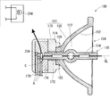
光源装置100は、露光対象物Xの露光に適した波長を含む光を放射する。光源装置100は、図4に示すように、大略、放電灯110と、リフレクタ150と、絶縁ベース170とで構成されている。なお、リフレクタ150と絶縁ベース170とをまとめてリフレクタ容器151と記載することがある。
紫外線光源200は、本実施例の場合、紫外光を放射するLEDであり、各光源装置100に組み込まれている。そこで、本実施例における紫外線光源200の説明は、光源装置100の説明と併せて行う。なお、紫外線光源200はLEDに限定されるものではなく、紫外光を放射できるものであれば、高圧水銀ランプやメタルハライドランプ等を使用してもよい。とりわけ、後述する変形例1に示すように、複数の放電灯110に対して紫外光を照射する場合には、1個あたりの発光量が多いランプを選択するのが好適である。
放電灯110は、図5に示すように、発光管部112と、当該発光管部112から延出する一対のシール部114とを有している。発光管部112および一対のシール部114は、石英ガラスで一体的に形成されている。さらに、発光管部112内にはシール部114によって密閉された内部空間116が形成されている。
放電灯110の各シール部114内には、埋設されたモリブデン製の箔118と、一端が箔118の一方端部に接続されているとともに他端が内部空間116内に配置されたタングステン製の一対の電極120と、一端が箔118の他方端部に接続されているとともに他端がシール部114から外部へ延出する一対のリード棒122とがそれぞれ設けられている。また、内部空間116には、所定量の水銀124およびハロゲン(例えば臭素)が封入されている。
放電灯110に設けられた一対のリード棒122に所定の高電圧を印加すると、発光管部112の内部空間116に設けられた一対の電極120間で開始したグロー放電がアーク放電に移行し、このアークによって蒸発および励起された水銀124によって光(主に紫外線)が放射される。
図4に戻って、本実施例にかかる光源装置100では、一方のシール部114がリフレクタ150のシール部挿設孔156に挿設されている。なお、放電灯110は、交流点灯用でも直流点灯用でもよい。
リフレクタ150は、椀状の反射面152をその内側表面に有している。この反射面152は、リフレクタ150の内側に発光管部112が位置するように配置された放電灯110からの光の一部を反射させる。本実施例では、この反射面152は回転放物面で規定されている。また、放電灯110における発光点(概略、内部空間116における一対の電極120間に形成されたアークの中央位置)は当該回転放物面の焦点に一致している。これにより、放電灯110の発光点から放射され、反射面152で反射した後、リフレクタ150の開口154から出た光は、ほぼ平行光となる。もちろん、反射面152の形状はこれに限定されるものではなく、回転楕円面やその他の回転面、あるいは回転面以外の形状であってもよい。また、発光点を焦点に一致させることは必須ではなく、必要に応じて、発光点を焦点からずらしてもよい。
また、リフレクタ150における開口154とは反対側からは、底頸部155が突設されている。さらに、リフレクタ150の反射面152には、放電灯110にける一方のシール部114が挿設されるシール部挿設孔156が形成されている。このシール部挿設孔156は、反射面152の底から底頸部155の先端にかけて形成されている。
図1に示すように、放電灯110にリフレクタ150を組み合わせることにより、放電灯110から放射された光は、反射面152の中心軸CLに沿って進む光を中心として所定の角度(開き角)をもった範囲でリフレクタ150の前方に進むようになる。
図4に戻り、絶縁ベース170は、セラミック等の電気的絶縁体で形成されており、リフレクタ150の底頸部155およびシール部挿設孔156に挿設された放電灯110における一方のシール部114が挿入されるリフレクタ挿入穴172が形成されている。底頸部155およびシール部114がリフレクタ挿入穴172に挿入されることにより、絶縁ベース170がシール部挿設孔156を外側から覆うことになる。
また、絶縁ベース170には、上述したリフレクタ挿入穴172に連通する内側空間174が形成されており、さらに当該内側空間174と外側とを互いに連通して電源ケーブルAが挿通される電源ケーブル挿通穴176が形成されている。
さらに、絶縁ベース170および放電灯110は、電気絶縁性および高い熱伝導性を有する無機接着剤Cによって互いに固定されている。具体的に説明すると、絶縁ベース170のリフレクタ挿入穴172にリフレクタ150の底頸部155の端部、および、放電灯110の一方のシール部114を挿入し、さらに、絶縁ベース170の内側空間174に紫外線光源200および電源ケーブルAを配置した状態で、当該内側空間174に無機接着剤Cが充填されている。なお、紫外線光源200は、放電灯110の近傍に取り付けられており、さらに言えば、当該紫外線光源200からの紫外光が放電灯110におけるリフレクタ挿入穴172に挿入された側のシール部114の端面に向けて放射される位置に設けるのが好適である。
図3に戻り、フレーム52は、複数の光源装置100が装着される複数の凹所58が形成された略直方体状の部材である。
図2に戻り、放電灯用電源54は、フレーム52に取り付けられた各光源装置100の放電灯110に必要な電力(直流あるいは交流)を供給する。また、紫外線光源用電源56は、各光源装置100に組み込まれた紫外線光源200に直流の電流を供給する電源であり、紫外線光源用スイッチ55は紫外線光源200に供給する直流の定電流をオン・オフする。紫外線光源用電源56が供給する直流は、紫外線光源200を構成するLEDの順方向に流れるようになっている。
判定装置57は、各光源装置100(放電灯110)が純正品か否かを判定するための装置であり、図6に示すように、大略、制御部60と、判定部66とを有している。
制御部60は、放電灯用スイッチ53および紫外線光源用スイッチ55を操作して、放電灯用電源54から放電灯110に供給される電流をオン・オフするとともに、紫外線光源用電源56から紫外線光源200に供給される電流をオン・オフする機能を有する。
制御部60は基本的に2つの動作を行う。すなわち、制御部60は、1回目は紫外線光源用スイッチ55をオフにしたままで放電灯用スイッチ53をオンにして、2回目は紫外線光源用スイッチ55をオンにした状態で前記放電灯用スイッチ53をオンにする。
判定部66は、上述した制御部60による1回目の動作の結果、および、2回目の動作の結果、ともに放電灯用スイッチ53をオンにしたときに放電灯110が点灯した場合は放電灯110が純正品ではないと判定し、2回目に放電灯用スイッチ53をオンにしたとき(つまり、紫外線光源用スイッチ55をオンにした状態のとき)だけ放電灯110が点灯した場合は放電灯110が純正品であると判定する。
なお、判定部66における、放電灯110が点灯したか否かの判断は、例えば、放電灯用電源54から放電灯110に対して供給される電圧が高電圧(点灯[絶縁破壊]前)からより低い電圧(点灯[絶縁破壊]後)に変化したことをもって「放電灯110が点灯した」と判断してもよい。あるいは、放電灯110からの光を受けられる位置に光センサーを設け、当該光センサーが放電灯110からの光を受けたことをもって「放電灯110が点灯した」と判断することもできる。もちろん、他の手法をもって「放電灯110が点灯した」と判断してもよい。
(照射装置50における純正品判定の動作)
照射装置50の電源スイッチ(図示せず)が投入されると、判定装置57における制御部60が動作を開始し、フレーム52に取り付けられたいずれか1つの光源装置100における紫外線光源200に電力を供給する紫外線光源用スイッチ55をオフにしたままで、当該光源装置100における放電灯110に電力を供給する放電灯用スイッチ53をオンにして、当該放電灯110の点灯を試みる(1回目)。然る後、制御部60は、一旦、放電灯用スイッチ53をオフにする。そして、紫外線光源用スイッチ55をオンにするとともに、放電灯用スイッチ53を再びオンにする(2回目)。なお、判定装置57が動作するタイミングはこれに限定されるものではない。
照射装置50の電源スイッチ(図示せず)が投入されると、判定装置57における制御部60が動作を開始し、フレーム52に取り付けられたいずれか1つの光源装置100における紫外線光源200に電力を供給する紫外線光源用スイッチ55をオフにしたままで、当該光源装置100における放電灯110に電力を供給する放電灯用スイッチ53をオンにして、当該放電灯110の点灯を試みる(1回目)。然る後、制御部60は、一旦、放電灯用スイッチ53をオフにする。そして、紫外線光源用スイッチ55をオンにするとともに、放電灯用スイッチ53を再びオンにする(2回目)。なお、判定装置57が動作するタイミングはこれに限定されるものではない。
判定部66は、1回目および2回目の動作でそれぞれ放電灯110が点灯したか否かを判断し、その判断結果に基づいて上述のように当該放電灯110が純正品であるか否かを判定する。
1つ目の光源装置100における純正品判定が完了した後、制御部60は他の光源装置100における放電灯110への電流の供給を開始する。以降、上述した1つ目の光源装置100の場合と同様に純正品判定を行い、すべての光源装置100の判定を終了するまで、あるいは所定の範囲の光源装置100の検査を終了するまで同様の判定を繰り返す。
(照射装置50の特徴)
本実施例によれば、放電灯110における発光管部112の内部空間116にクリプトン85等の始動性促進物質を封入しなくても、紫外線光源200からの紫外光を照射することにより、当該放電灯110の始動性を改善することができた。
本実施例によれば、放電灯110における発光管部112の内部空間116にクリプトン85等の始動性促進物質を封入しなくても、紫外線光源200からの紫外光を照射することにより、当該放電灯110の始動性を改善することができた。
また、判定装置57により、放電灯110が純正品か否かを判定することができた。これにより、長期間使用して破裂の危険性がある純正品でない放電灯110が誤って使用され続けるのを回避できる。
(変形例1)
上述の実施例1では、複数の放電灯110のそれぞれに紫外線光源(LED)200が取り付けられていたが、図7に示すように、フレーム52に取り付けられた複数の光源装置100における放電灯110に向けて紫外光を照射できるように1つの紫外線光源200を配置してもよい。この場合、紫外線光源200からの紫外光は、光源装置100における各リフレクタ150の開口154を通って放電灯110の発光管部112を直接照射することになる。これにより、実施例1の場合と同様、放電灯110の始動性を改善することができる。なお、配置する紫外線光源200の数は、複数であってもよい。
上述の実施例1では、複数の放電灯110のそれぞれに紫外線光源(LED)200が取り付けられていたが、図7に示すように、フレーム52に取り付けられた複数の光源装置100における放電灯110に向けて紫外光を照射できるように1つの紫外線光源200を配置してもよい。この場合、紫外線光源200からの紫外光は、光源装置100における各リフレクタ150の開口154を通って放電灯110の発光管部112を直接照射することになる。これにより、実施例1の場合と同様、放電灯110の始動性を改善することができる。なお、配置する紫外線光源200の数は、複数であってもよい。
また、この変形例1の場合であっても放電灯110が純正品か否かを判定する方法は実施例1と同じである。1回目の動作では、紫外線光源200に給電する紫外線光源用スイッチ55をオフにしたままで、判定対象とする放電灯110に給電する放電灯用スイッチ53をオンにして当該放電灯110が点灯するか否かを確認する。そして、2回目の動作では、紫外線光源用スイッチ55をオンにした状態で、放電灯用スイッチ53をオンにして当該放電灯110が点灯するか否かを確認する。
然る後、1回目の動作の結果、および、2回目の動作の結果、ともに放電灯用スイッチ53をオンにしたときに放電灯110が点灯した場合は放電灯110が純正品ではないと判定し、2回目に放電灯用スイッチ53をオンにしたとき(つまり、紫外線光源用スイッチ55をオンにした状態のとき)だけ放電灯110が点灯した場合は放電灯110が純正品であると判定する。
(変形例2)
上述の実施例における光源装置100の紫外線光源200は、LEDのみで構成されていたが、図8に示すように、紫外線光源200を、LED202と、当該LED202に対して直列に接続された白熱灯204とで構成し、光源装置100(より正確には、実施例1と同様に絶縁ベース170の内側空間174)に設けてもよい。なお、回路保護等のため、LED202や白熱灯204に対して直列にフューズを取り付けてもよい。
上述の実施例における光源装置100の紫外線光源200は、LEDのみで構成されていたが、図8に示すように、紫外線光源200を、LED202と、当該LED202に対して直列に接続された白熱灯204とで構成し、光源装置100(より正確には、実施例1と同様に絶縁ベース170の内側空間174)に設けてもよい。なお、回路保護等のため、LED202や白熱灯204に対して直列にフューズを取り付けてもよい。
この場合、光源装置100の純正品判定は、最初に説明した実施例1と同様に紫外線光源200を用いるやり方と、白熱灯204を用いるやり方とを組み合わせることが可能となる。両方のやり方を同時に実施してもよいし、いずれか一方を実施することもできる。
この変形例2において、白熱灯204を用いた純正品判定は、紫外線光源用電源56から白熱灯204に対して、制御部60により定電流を供給し続けた状態で、所定の時間(例えば10秒)をあけて2回、紫外線光源200の両端電圧を測定することによって行う。
紫外線光源200に対して定電流を供給開始した後、当該紫外線光源200の両端電圧を判定装置57の測定部(図示せず。以下、同じ。)で測定する(1回目)。次に、所定の時間(例えば、10秒)が経過した後、測定部がふたたび紫外線光源200の両端電圧を測定する(2回目)。測定された2回分の両端電圧値は、判定装置57の判定部66に送られる。なお、紫外線光源200に流す定電流は、LED202の順方向電流に該当する直流である。
2回分の両端電圧値を受け取った判定部66は、2回分の両端電圧値の差が所定の電圧範囲内にあるか否かを確認し、両端電圧値の差が所定の電圧範囲内にある場合、判定部66は、検査対象の放電灯110が純正品であると判定する。逆に、両端電圧値の差が所定の電圧範囲内にない場合、判定部66は、検査対象の放電灯110が純正品ではないと判定する。
一般的に、白熱灯204は、それに含まれるフィラメントの特性上、電流を通電してしばらく(10数秒)の間は抵抗値が増加する傾向にある。このため、2回目に測定した紫外線光源200の両端電圧値(例えば8.5V)は、1回目に測定した同じ両端電圧の値(例えば2.0V)に比べて大きくなる。これにより、上述した2回の測定による両端電圧値の差が所定の電圧範囲内(例えば、6から7Vの間)にある場合、その放電灯110は白熱灯204を備える純正品であると判定することができる。
これに対し、放電灯110が純正品でない場合、紫外線光源200は白熱灯204を備えていないことから、紫外線光源200の両端電圧値における1回目の測定値と2回目の測定値との差はほぼゼロになる。したがって、両端電圧値の差が所定の電圧範囲内にない場合、判定部66は、検査対象の放電灯110が純正品ではないと判定する。
(変形例3)
上述した変形例1のように、フレーム52に取り付けられた複数の光源装置100における放電灯110に向けて紫外光を照射する紫外線光源200を配置する場合、図9に示すように、LED202ではなく、白熱灯204のみを光源装置100に設けてもよい。なお、白熱灯204は、絶縁ベース170内のいずれに配置してもよいし、絶縁ベース170の外面や、リフレクタ150の外面などに配置することによってリフレクタ容器151に取り付けてもよい。また、回路保護等のため、白熱灯204に対して直列にフューズを取り付けてもよい。
上述した変形例1のように、フレーム52に取り付けられた複数の光源装置100における放電灯110に向けて紫外光を照射する紫外線光源200を配置する場合、図9に示すように、LED202ではなく、白熱灯204のみを光源装置100に設けてもよい。なお、白熱灯204は、絶縁ベース170内のいずれに配置してもよいし、絶縁ベース170の外面や、リフレクタ150の外面などに配置することによってリフレクタ容器151に取り付けてもよい。また、回路保護等のため、白熱灯204に対して直列にフューズを取り付けてもよい。
この場合、光源装置100の純正品判定は、変形例1と同様に紫外線光源200を用いるやり方と、白熱灯204を用いるやり方とを組み合わせることが可能となる。両方のやり方を同時に実施してもよいし、順番に実施してもよいし、いずれか一方を実施することもできる。
白熱灯204を用いた純正品判定について説明する。白熱灯204を用いた純正品判定は、紫外線光源用電源56あるいは別の電源(図示せず)から白熱灯204に対して、制御部60により定電流(交流でも直流でもよい)を供給し続けた状態で、所定の時間(例えば10秒)をあけて2回、白熱灯204に接続される一対の電源ケーブルAの両端電圧を測定することによって行う。
白熱灯204に対して定電流を供給開始した後、当該白熱灯204の両端電圧を判定装置57の測定部(図示せず。以下、同じ。)で測定する(1回目)。次に、所定の時間(例えば、10秒)が経過した後、測定部がふたたび白熱灯204の両端電圧を測定する(2回目)。測定された2回分の両端電圧値は、判定装置57の判定部66に送られる。
2回分の両端電圧値を受け取った判定部66は、2回分の両端電圧値の差が所定の電圧範囲内にあるか否かを確認し、両端電圧値の差が所定の電圧範囲内にある場合、判定部66は、検査対象の放電灯110が純正品であると判定する。逆に、両端電圧値の差が所定の電圧範囲内にない場合、判定部66は、検査対象の放電灯110が純正品ではないと判定する。
放電灯110が白熱灯204を備えている純正品である場合、白熱灯204の両端電圧値は、1回目の測定値よりも、2回目の測定値の方が大きくなる。この理由は、変形例2で説明したものと同じであるからそれを援用して省略する。これにより、上述した2回の測定による両端電圧値の差が所定の電圧範囲内(例えば、6から7Vの間)にある場合、その放電灯110は白熱灯204を備えている純正品であると判定することができる。
これに対し、放電灯110が純正品でない場合、白熱灯204を備えていないことから、電源ケーブルAの両端電圧値における1回目の測定値と2回目の測定値との差はほぼゼロになる。したがって、両端電圧値の差が所定の電圧範囲内にない場合、判定部66は、検査対象の放電灯110が純正品ではないと判定する。
今回開示された実施の形態はすべての点で例示であって制限的なものではないと考えられるべきである。本発明の範囲は、上記した説明ではなく、特許請求の範囲によって示され、特許請求の範囲と均等の意味および範囲内でのすべての変更が含まれることが意図される。
10…露光機、12…インテグレータ、14…凹面鏡、16…照射面、18…入射面、20…出射面、21…フライアイレンズ、22…反射凹面
50…照射装置、52…フレーム、53…放電灯用スイッチ、54…放電灯用電源、55…紫外線光源用スイッチ、56…紫外線光源用電源、57…判定装置、58…凹所、60…制御部、66…判定部
100…光源装置
110…放電灯、112…発光管部、114…シール部、116…内部空間、118…箔、120…電極、122…リード棒、124…水銀
150…リフレクタ、151…リフレクタ容器、152…反射面、154…開口、155…底頸部、156…シール部挿設孔
170…絶縁ベース、172…リフレクタ挿入穴、174…内側空間、176…電源ケーブル挿通穴
200…紫外線光源、202…LED、204…白熱灯
50…照射装置、52…フレーム、53…放電灯用スイッチ、54…放電灯用電源、55…紫外線光源用スイッチ、56…紫外線光源用電源、57…判定装置、58…凹所、60…制御部、66…判定部
100…光源装置
110…放電灯、112…発光管部、114…シール部、116…内部空間、118…箔、120…電極、122…リード棒、124…水銀
150…リフレクタ、151…リフレクタ容器、152…反射面、154…開口、155…底頸部、156…シール部挿設孔
170…絶縁ベース、172…リフレクタ挿入穴、174…内側空間、176…電源ケーブル挿通穴
200…紫外線光源、202…LED、204…白熱灯
Claims (8)
- 光源となる放電灯と、
前記放電灯が純正品であるかどうかを検出するための白熱灯と、
前記放電灯および前記白熱灯が取り付けられたリフレクタ容器とを備える光源装置であって、
前記放電灯は、外部に設けられた紫外線光源からの紫外線の照射を受けて点灯することを特徴とする
光源装置。 - 光源となる放電灯と、
前記放電灯の始動時において、前記放電灯が純正品であるかどうかを検出するために前記放電灯に対して紫外光を照射する紫外線光源とを備える照射装置。 - 複数の前記放電灯を備えており、前記紫外線光源は複数の前記放電灯に対して前記紫外光を照射することを特徴とする請求項2に記載の照射装置。
- 前記紫外線光源は前記放電灯の近傍に取り付けられており、ひとつの前記紫外線光源は、ひとつの前記放電灯に対して前記紫外光を照射することを特徴とする請求項2に記載の照射装置。
- 前記紫外線光源はLEDであることを特徴とする、請求項2から4のいずれか1項に記載の照射装置。
- 前記紫外線光源は、LEDと、前記LEDに対して直列に接続された白熱灯とを有していることを特徴とする、請求項2から4のいずれか1項に記載の照射装置。
- 前記放電灯に点灯用の電力を供給する放電灯用電源と、
前記紫外線光源に点灯用の電力を供給する紫外線光源用電源と、
前記放電灯用電源からの前記電力をオン・オフする放電灯用スイッチと、
前記紫外線光源用電源からの前記電力をオン・オフする紫外線光源用スイッチと、
前記放電灯用スイッチおよび前記紫外線光源用スイッチをオン・オフする機能を有しており、1回目は前記紫外線光源用スイッチをオフにしたままで前記放電灯用スイッチをオンにして、2回目は前記紫外線光源用スイッチをオンにした状態で前記放電灯用スイッチをオンにする制御部と、
1回目および2回目ともに前記放電灯用スイッチをオンにしたときに前記放電灯が点灯した場合は前記放電灯が純正品ではないと判定し、2回目に前記放電灯用スイッチをオンにしたときだけ前記放電灯が点灯した場合は前記放電灯が純正品であると判定する判定部とをさらに備えている、請求項2から6のいずれか1項に記載の照射装置。 - 1回目は、紫外線光源用電源から供給された紫外線光源の点灯用の電力をオン・オフする紫外線光源用スイッチをオフにしたままで、放電灯用電源から供給された放電灯の点灯用の電力をオン・オフする放電灯用スイッチをオンにして、
2回目は、前記紫外線光源用スイッチをオンにした状態で、前記放電灯用スイッチをオンにして、
1回目および2回目ともに前記放電灯用スイッチをオンにしたときに前記放電灯が点灯した場合は前記放電灯が純正品ではないと判定し、2回目に前記放電灯用スイッチをオンにしたときだけ前記放電灯が点灯した場合は前記放電灯が純正品であると判定する
放電灯の判定方法。
Priority Applications (3)
| Application Number | Priority Date | Filing Date | Title |
|---|---|---|---|
| JP2020506403A JP7274761B2 (ja) | 2018-03-13 | 2019-03-01 | 放電灯を含む光源装置、照射装置、および放電灯の判定方法 |
| US16/978,331 US11913985B2 (en) | 2018-03-13 | 2019-03-01 | Light source device including discharge lamp, irradiation device and distinguishing method for discharge lamp |
| CN201980016097.6A CN111819496B (zh) | 2018-03-13 | 2019-03-01 | 包括放电灯的光源装置、照射装置以及放电灯的判定方法 |
Applications Claiming Priority (2)
| Application Number | Priority Date | Filing Date | Title |
|---|---|---|---|
| JP2018046077 | 2018-03-13 | ||
| JP2018-046077 | 2018-03-13 |
Publications (1)
| Publication Number | Publication Date |
|---|---|
| WO2019176600A1 true WO2019176600A1 (ja) | 2019-09-19 |
Family
ID=67907669
Family Applications (1)
| Application Number | Title | Priority Date | Filing Date |
|---|---|---|---|
| PCT/JP2019/008241 WO2019176600A1 (ja) | 2018-03-13 | 2019-03-01 | 放電灯を含む光源装置、照射装置、および放電灯の判定方法 |
Country Status (5)
| Country | Link |
|---|---|
| US (1) | US11913985B2 (ja) |
| JP (1) | JP7274761B2 (ja) |
| CN (1) | CN111819496B (ja) |
| TW (1) | TWI808136B (ja) |
| WO (1) | WO2019176600A1 (ja) |
Citations (5)
| Publication number | Priority date | Publication date | Assignee | Title |
|---|---|---|---|---|
| JP2007317529A (ja) * | 2006-05-26 | 2007-12-06 | Mitsubishi Electric Corp | 高圧放電ランプ |
| JP3137962U (ja) * | 2007-10-03 | 2007-12-13 | 岩崎電気株式会社 | 光源装置 |
| JP2009212041A (ja) * | 2008-03-06 | 2009-09-17 | Phoenix Denki Kk | 補助光源およびその補助光源を備える光源装置 |
| JP2011014247A (ja) * | 2009-06-30 | 2011-01-20 | Iwasaki Electric Co Ltd | 光源装置 |
| JP2016200751A (ja) * | 2015-04-13 | 2016-12-01 | フェニックス電機株式会社 | 光源装置及び露光装置とその検査方法 |
Family Cites Families (6)
| Publication number | Priority date | Publication date | Assignee | Title |
|---|---|---|---|---|
| JP4826446B2 (ja) * | 2006-11-27 | 2011-11-30 | ウシオ電機株式会社 | 光源装置 |
| JP3137961U (ja) * | 2007-10-03 | 2007-12-13 | 岩崎電気株式会社 | 光源装置 |
| DE102008058819A1 (de) * | 2007-11-28 | 2009-06-25 | Toshiba Lighting & Technology Corp. | Entladungslampenzündvorrichtung |
| JP4788719B2 (ja) | 2008-02-01 | 2011-10-05 | パナソニック株式会社 | 高圧放電ランプシステム、およびそれを用いたプロジェクタ |
| CN102428538A (zh) * | 2009-05-14 | 2012-04-25 | 岩崎电气株式会社 | 光源装置 |
| JP4995342B1 (ja) * | 2011-11-21 | 2012-08-08 | フェニックス電機株式会社 | 露光用光源およびこれを用いた露光装置 |
-
2019
- 2019-03-01 WO PCT/JP2019/008241 patent/WO2019176600A1/ja active Application Filing
- 2019-03-01 CN CN201980016097.6A patent/CN111819496B/zh active Active
- 2019-03-01 US US16/978,331 patent/US11913985B2/en active Active
- 2019-03-01 JP JP2020506403A patent/JP7274761B2/ja active Active
- 2019-03-11 TW TW108107961A patent/TWI808136B/zh active
Patent Citations (5)
| Publication number | Priority date | Publication date | Assignee | Title |
|---|---|---|---|---|
| JP2007317529A (ja) * | 2006-05-26 | 2007-12-06 | Mitsubishi Electric Corp | 高圧放電ランプ |
| JP3137962U (ja) * | 2007-10-03 | 2007-12-13 | 岩崎電気株式会社 | 光源装置 |
| JP2009212041A (ja) * | 2008-03-06 | 2009-09-17 | Phoenix Denki Kk | 補助光源およびその補助光源を備える光源装置 |
| JP2011014247A (ja) * | 2009-06-30 | 2011-01-20 | Iwasaki Electric Co Ltd | 光源装置 |
| JP2016200751A (ja) * | 2015-04-13 | 2016-12-01 | フェニックス電機株式会社 | 光源装置及び露光装置とその検査方法 |
Also Published As
| Publication number | Publication date |
|---|---|
| TWI808136B (zh) | 2023-07-11 |
| CN111819496A (zh) | 2020-10-23 |
| TW201945858A (zh) | 2019-12-01 |
| JP7274761B2 (ja) | 2023-05-17 |
| CN111819496B (zh) | 2023-10-03 |
| US11913985B2 (en) | 2024-02-27 |
| JPWO2019176600A1 (ja) | 2021-03-11 |
| US20210003627A1 (en) | 2021-01-07 |
Similar Documents
| Publication | Publication Date | Title |
|---|---|---|
| CN107478976B (zh) | 光源装置 | |
| WO2019176600A1 (ja) | 放電灯を含む光源装置、照射装置、および放電灯の判定方法 | |
| JP5524931B2 (ja) | 補助ランプ付き高圧放電ランプ | |
| CN111066376B (zh) | 光源装置、曝光装置以及光源装置的判定方法 | |
| JP7141126B2 (ja) | 光源装置、露光装置、および光源装置の判定方法 | |
| WO2019111769A1 (ja) | ランプの点灯方法 | |
| KR102538972B1 (ko) | 광원 장치, 그것을 구비하는 조사 장치, 및 광원 장치의 점등 방법 | |
| JP2009164074A (ja) | 放電ランプ | |
| JPH113604A (ja) | 照明器具 |
Legal Events
| Date | Code | Title | Description |
|---|---|---|---|
| 121 | Ep: the epo has been informed by wipo that ep was designated in this application |
Ref document number: 19767306 Country of ref document: EP Kind code of ref document: A1 |
|
| ENP | Entry into the national phase |
Ref document number: 2020506403 Country of ref document: JP Kind code of ref document: A |
|
| NENP | Non-entry into the national phase |
Ref country code: DE |
|
| 122 | Ep: pct application non-entry in european phase |
Ref document number: 19767306 Country of ref document: EP Kind code of ref document: A1 |