WO2019167397A1 - リニアモータ - Google Patents
リニアモータ Download PDFInfo
- Publication number
- WO2019167397A1 WO2019167397A1 PCT/JP2018/047004 JP2018047004W WO2019167397A1 WO 2019167397 A1 WO2019167397 A1 WO 2019167397A1 JP 2018047004 W JP2018047004 W JP 2018047004W WO 2019167397 A1 WO2019167397 A1 WO 2019167397A1
- Authority
- WO
- WIPO (PCT)
- Prior art keywords
- magnetic pole
- linear motor
- permanent magnet
- magnetic
- field element
- Prior art date
- Legal status (The legal status is an assumption and is not a legal conclusion. Google has not performed a legal analysis and makes no representation as to the accuracy of the status listed.)
- Ceased
Links
Images







Classifications
-
- H—ELECTRICITY
- H02—GENERATION; CONVERSION OR DISTRIBUTION OF ELECTRIC POWER
- H02K—DYNAMO-ELECTRIC MACHINES
- H02K41/00—Propulsion systems in which a rigid body is moved along a path due to dynamo-electric interaction between the body and a magnetic field travelling along the path
- H02K41/02—Linear motors; Sectional motors
- H02K41/03—Synchronous motors; Motors moving step by step; Reluctance motors
Definitions
- the present invention relates to a linear motor.
- a linear motor having a thrust generating mechanism has a shape in which a rotating machine is opened in a straight line, and generates a thrust in the mover by a magnetic force acting between magnetic poles formed in each of the stator and the mover.
- linear motors described in WO2014 / 064785A1 Patent Document 1
- WO2011 / 155022A1 Patent Document 2
- a permanent magnet is fixed to a plurality of magnet holding holes of a magnet holding member (see FIG. 31).
- high-permeability members are installed on the upper and lower surfaces of the permanent magnet using an adhesive or the like (see paragraph 0021, FIG. 3A and FIG. 3B).
- a permanent magnet is bonded to a magnet holding member, and armature magnetic poles are arranged opposite to each other with a gap on both sides of the permanent magnet. Therefore, the influence of the reverse magnetic field that the permanent magnet receives from the armature magnetic pole is large, and the permanent magnet is likely to be demagnetized.
- a high permeability member is provided on each of the upper and lower surfaces of the permanent magnet in order to increase the rigidity of the mover (field element) while reducing the amount of magnets to make it difficult to bend. .
- a high permeability member between the permanent magnet and the armature magnetic pole, the influence of the reverse magnetic field received by the permanent magnet from the armature magnetic pole is suppressed, and the demagnetization resistance Can be improved.
- an adhesive is used to install the high-permeability member on the surface of the permanent magnet, and there are not a few adhesive layers between the two. . This adhesive layer becomes a magnetic resistance in the magnetic circuit, and may reduce the magnetic characteristics and thrust characteristics of the linear motor.
- An object of the present invention is to propose a linear motor having a field element that suppresses deterioration of magnetic characteristics and improves the demagnetization resistance of a permanent magnet.
- the linear motor of the present invention is In a linear motor having a field element and a plurality of armature magnetic poles provided across the field element, the field element and the armature magnetic pole being relatively displaced,
- the field element has a plurality of permanent magnet magnetic poles arranged along a direction in which the field element and the armature magnetic pole are relatively displaced, and an edge surrounding the permanent magnet magnetic pole.
- a magnetic pole frame that supports, and a magnetic body that is provided so as to be in contact with a surface facing the armature magnetic pole of the permanent magnet magnetic pole, The magnetic body extends beyond the edge to the magnetic pole frame.
- FIG. 1 is a perspective view of a linear motor according to Embodiment 1.
- FIG. FIG. 3 is a perspective view illustrating a cross section perpendicular to the left-right direction of the linear motor according to the first embodiment. Sectional drawing perpendicular
- FIG. The figure seen from the upper part of the needle
- FIG. The figure which shows distribution of the irreversible demagnetization part of a permanent magnet magnetic pole about the comparative example (1st comparative example) with this invention.
- FIG. 3 is a perspective view illustrating a structure for fixing a magnetic cover to the mover in the first embodiment.
- Schematic which shows a cross section perpendicular
- Schematic which shows a cross section perpendicular
- FIG. Schematic which shows a cross section perpendicular
- FIG. 9 is a configuration diagram of a vehicle air suspension according to a sixth embodiment.
- the front-rear direction coincides with the drive direction of the mover 2, and the up-down direction is perpendicular to the magnetic pole surface of the permanent magnet magnetic pole 210 (surface on which S and N poles are generated).
- the movable element 2 may be described by having the longitudinal direction as the longitudinal direction and the left-right direction as the width direction of the movable element 2.
- the direction along the moving direction (front-rear direction) of the mover 2 is the first direction
- the direction along the width direction (left-right direction) of the field element perpendicular to the first direction is the second direction, the first direction, and the second direction.
- the direction along the thickness direction (vertical direction) of the field element perpendicular to the direction may be described as the third direction.
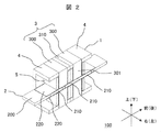
- FIG. 1 is a perspective view of the linear motor according to the first embodiment.
- FIG. 2 is a perspective view illustrating a cross section perpendicular to the left-right direction of the linear motor according to the first embodiment.
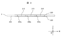
- FIG. 3 is a cross-sectional view perpendicular to the left-right direction of the mover of the linear motor according to the first embodiment.
- FIG. 4 is a top view of the mover of the linear motor according to the first embodiment.
- the linear motor 100 includes a stator 1 and a mover 2.
- the armature side is described as a stator that is stationary with respect to the ground
- the field element side is described as a mover that moves in the front-rear direction with respect to the ground. There may be. That is, the linear motor 100 is configured such that the field element and the armature (armature magnetic pole) are relatively displaced.
- the stator 1 includes an armature 3, end members 4 disposed on the front side and the rear side of the armature 3, and a winding 5.
- the armature 3 includes a soft magnetic core 300 and spacers 310, and the plurality of cores 300 are connected by soft magnetic spacers 310. Thus, a magnetic path including a plurality of cores 300 and spacers 310 can be formed.
- the core 300 has magnetic pole teeth (armature magnetic poles) 301 on the upper and lower sides, and the winding 5 is wound around each.
- armatures 3 can be arranged in the front-rear direction. Further, the end member 4 can be provided on the front side of the frontmost armature 3 and / or on the rear side of the rearmost armature 3.
- the core 300 includes magnetic pole teeth 301 that are arranged to face each other with the mover 2 interposed therebetween, and arm portions 302 that connect the two magnetic pole teeth 301.
- the magnetic pole teeth 301 and the arm portions 302 can be configured by, for example, stacking electromagnetic steel plates in the front-rear direction.
- a winding 5 is wound around the magnetic pole teeth 301.
- the arm portion 302 is a soft magnetic material that extends in the vertical direction on both outer sides of the winding 5 and the mover 2 in the left-right direction.
- the arm portion 302 generates a magnetic flux emitted from the permanent magnet magnetic pole 210 and entering the magnetic pole teeth 301.
- the magnetic pole teeth 301 can be guided to another magnetic pole tooth 301 that faces the magnetic pole teeth 301 via the mover 2.
- the core 300 has a magnetic pole tooth 301, a permanent magnet magnetic pole 210 facing the magnetic pole tooth 301, and a magnetic pole facing the permanent magnet magnetic pole 210 on the surface opposite to the side facing the magnetic pole tooth 301.
- a magnetic path including the teeth 301 and the arm portions 302 can be formed.
- the spacer 310 can pass the magnetic flux flowing through the adjacent core 300.
- the spacer 310 can be configured by, for example, stacking electromagnetic steel plates in the front-rear direction.
- the armature 3 in which the spacer 310 is disposed between the two cores 300 includes a magnetic path including the two adjacent cores 300 and the permanent magnet magnetic poles 210 according to the design such as the distance between the permanent magnet magnetic poles 210 in the front-rear direction. Can be formed.
- the end member 4 can be formed of a soft magnetic material or a nonmagnetic material.
- the end member 4 is fixed together with the core 300 and the spacer 310 by a fixing member such as a through bolt (not shown) extending in the front-rear direction. Further, a support member such as a bearing (not shown) is arranged on the end member 4 to support the mover 2.
- the mover 2 has the longitudinal direction as the longitudinal direction.
- the mover 2 includes a magnetic pole frame 200 made of a non-magnetic material or a soft magnetic material that fixes a plurality of permanent magnets in the front-rear direction, a permanent magnet magnetic pole 210 provided on the magnetic pole frame 200, and the permanent magnet magnetic pole 210 and the magnetic pole frame 200.
- the magnetic cover 220 is disposed on the upper side and the lower side.
- the mover 2 of the present embodiment is a mode in which three permanent magnet magnetic poles 210 are fixed.
- the plurality of permanent magnet magnetic poles 210 are arranged along a direction in which the mover 2 constituted by a field element and the stator 1 constituted by an armature magnetic pole 301 are relatively displaced. There may be three or more permanent magnet magnetic poles 210 or less.
- the permanent magnet magnetic poles 210 are respectively magnetized in the vertical direction, and the upper surfaces of the adjacent magnetic poles 210 are arranged so that N poles and S poles are alternated.
- the mover 2 is arranged in a space between the two magnetic pole teeth 301 in the vertical direction and between the two arm portions 302 in the horizontal direction.
- the permanent magnet magnetic pole 210 can be formed in a flat plate shape perpendicular to the vertical direction.
- the permanent magnet magnetic pole 210 has a flat plate shape with a width dimension in the left-right direction and a length dimension in the front-rear direction that is greater than the thickness dimension in the vertical direction.
- the vertical direction is a direction in which the magnetic pole teeth 301 and the permanent magnet magnetic pole 210 are opposed to each other.
- the mover 2 is composed of a field element.
- the magnetic pole frame 200 can have a ladder shape including a plurality of gaps 200a into which the permanent magnet magnetic poles 210 are fitted.
- the permanent magnet magnetic pole 210 is fixed to the magnetic pole frame 200 without being pulled out in the left-right direction and the front-rear direction by being fitted into the gap 200a.
- the magnetic pole frame 200 has an edge of the air gap 200a surrounding the permanent magnet magnetic pole, and supports the permanent magnet magnetic pole 210.
- the gap 200a is formed as a through-hole penetrating the magnetic pole frame 200 in the vertical direction, and constitutes a fitting portion into which the permanent magnet magnetic pole 210 is fitted in the vertical direction.
- the permanent magnet magnetic pole 210 is disposed in the gap (insertion portion) 200a so as to fill the gap (insertion portion) 200a, thereby preventing displacement in the left-right direction and the front-rear direction.
- the magnetic pole frame 200 may be formed of a soft magnetic material or a non-magnetic material.
- FIG. 1 The concave portion is formed in a concave shape on one end surface of the magnetic pole frame 200 in the vertical direction. This concave portion can also be regarded as a kind of gap (insertion portion) 200a into which the permanent magnet magnetic pole 210 is inserted.
- the permanent magnet magnetic pole 210 may be composed of a rare earth magnet such as a neodymium magnet, or a permanent magnet made of another material such as a ferrite magnet.
- the magnetic cover 220 is on the vertical surface of the mover 2 and extends not only to the vertical surface of the permanent magnet magnetic pole 210 but also to the vertical surface of the magnetic pole frame 200, and the magnetic pole frame 200 and the permanent magnet magnetic pole 210. These are provided so as to be in contact with each other on the upper and lower surfaces. That is, the magnetic cover 220 extends to the magnetic pole frame 200 beyond the edge of the air gap 200a surrounding the permanent magnet magnetic pole 210 of the magnetic pole frame 200 so as to contact the surface of the permanent magnet magnetic pole 210 facing the armature magnetic pole 301. Yes.
- the magnetic cover 220 is made of a magnetic material.
- the magnetic cover 220 may be made of, for example, an iron-based material containing iron, a thin plate such as magnetic stainless steel or an electromagnetic steel plate, or may be made of an amorphous metal or a dust core.
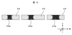
- FIG. 5 is a diagram showing a distribution of irreversible demagnetization sites of the permanent magnet magnetic poles in a comparative example (first comparative example) with the present invention. In FIG. 5, the magnetic pole frame is not shown.
- the magnetic cover 220 in the first embodiment is not provided, and the mover 2 is configured only by the magnetic pole frame 200 and the permanent magnet magnetic pole 210.
- the dark-colored portion in FIG. 5 is a portion where irreversible demagnetization occurs (irreversible demagnetization portion 210a). Irreversible demagnetization is a phenomenon in which the magnetic force of the permanent magnet is irreversibly weakened due to the influence of temperature and an external magnetic field, and means that the thrust of the linear motor 100 is reduced.
- the color of the central portion of each permanent magnet magnetic pole 210 is dark, and irreversible demagnetization occurs in the portion.
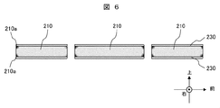
- FIG. 6 is a diagram showing a distribution of irreversible demagnetization sites of the permanent magnet magnetic poles in a comparative example (second comparative example) with the present invention.
- the magnetic pole frame is not shown.
- the mover 2 includes a magnetic pole frame 200, a permanent magnet magnetic pole 210, and a magnetic body 230, and the magnetic body 230 is disposed on the surface of the permanent magnet magnetic pole 210.
- the magnetic cover 230 covers only the surface of the permanent magnet magnetic pole 210.
- the color of the corner (end) of each permanent magnet magnetic pole 210 is dark.
- the portion causing irreversible demagnetization is smaller than that in the first comparative example, but irreversible demagnetization occurs at the corners of the permanent magnet magnetic pole 210.
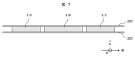
- FIG. 7 is a diagram showing a distribution of irreversible demagnetization sites of the permanent magnet magnetic poles in the configuration of the first embodiment. In FIG. 7, the magnetic pole frame is not shown.
- the mover 2 includes a magnetic pole frame 200, a permanent magnet magnetic pole 210, and a magnetic cover 220.
- the magnetic cover 220 extends not only to the vertical surface (end surface) of the permanent magnet magnetic pole 210 but also to the vertical surface of the magnetic pole frame 200. That is, the magnetic cover 220 is provided so as to protrude outward from the peripheral edge of the permanent magnet magnetic pole 210.
- each permanent magnet magnetic pole 210 has no dark portion and does not cause irreversible demagnetization.
- the configuration of the present embodiment can improve the demagnetization resistance of the permanent magnet magnetic pole and suppress the reduction in the thrust of the linear motor 100 due to the irreversible demagnetization.
- the magnetic cover 220 is provided on one end surface of the permanent magnet magnetic pole 210, and the other end surface of the permanent magnet magnetic pole 210 is nonmagnetic. It will be covered with the body. Even with such a configuration, an effect of improving the demagnetization resistance of the permanent magnet magnetic pole 210 and an effect of suppressing a reduction in thrust of the linear motor 100 due to irreversible demagnetization can be obtained.
- the air gap 200a is constituted by a through-hole
- the effect of improving the demagnetization resistance of the permanent magnet magnetic pole 210 and the irreversible demagnetization can be achieved only by providing the magnetic cover 220 on one end face in the vertical direction of the permanent magnet magnetic pole 210.
- the effect which suppresses the thrust fall of the linear motor 100 accompanying this is acquired.
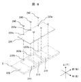
- FIG. 8 is a perspective view showing a structure for fixing the magnetic cover to the mover in the first embodiment. After the permanent magnet magnetic pole 210 is inserted into the gap (insertion portion) 200a of the magnetic pole frame 200 having the screw hole 200b, the magnetic cover 220 having the hole 220a is placed on the upper surface of the mover 2, and the magnetic cover 220 is used using the screw 240. Is fastened to the magnetic pole frame 200.
- the screw hole 200b can be provided outside the permanent magnet magnetic pole 210.
- the screw hole 200b is provided in a part of the magnetic pole frame 200 outside the permanent magnet magnetic pole 210 in the left-right direction, but may be provided in a part of the magnetic pole frame 200 outside the permanent magnet magnetic pole 210 in the front-rear direction. That is, the magnetic pole frame 200 may be provided between the adjacent permanent magnet magnetic poles 210.
- the magnetic cover 220 When extending the magnetic cover 220 to the vertical surface of the magnetic pole frame 200, the magnetic cover 220 may extend in the left-right direction with respect to the permanent magnet magnetic pole 210, may extend in the front-rear direction, or may be extended in the left-right direction and the front-rear direction. You may extend in both directions. That is, the magnetic cover 220 may be extended in at least one of the left-right direction and the front-rear direction with respect to the permanent magnet magnetic pole 210.
- the magnetic cover 220 can also be used as a member that reinforces the magnetic pole frame 200.
- the magnetic cover 220 extends in both the left-right direction and the front-rear direction, so that the effect of reinforcing the magnetic pole frame 200 is enhanced. Further, the magnetic cover 220 extends in both the left-right direction and the front-rear direction, thereby improving the demagnetization resistance of the permanent magnet magnetic pole and increasing the effect of suppressing the thrust reduction of the linear motor 100 due to irreversible demagnetization.
- FIG. 8 shows only the upper side of the mover 2, but it can be fixed to the lower side of the mover 2 in the same manner.
- the magnetic cover 220 is fixed to the lower side of the mover 2 and the permanent magnet magnetic pole 210 is inserted into the gap 200a. At this time, since the magnetic cover 220 is provided below the gap 200a, the permanent magnet magnetic pole 210 fitted into the gap 200a can be supported in the gap 200a. Thereafter, the magnetic cover 220 is placed on the upper surface of the mover 2 to hold the permanent magnet magnetic pole 210 in the gap 200a. Thereby, the needle
- the magnetic cover 220 may be divided for each permanent magnet magnetic pole 210 or may be divided into a plurality of magnetic covers 220 including magnetic covers corresponding to the plurality of permanent magnet magnetic poles 210.
- the magnetic cover 220 provided on the upper side of the mover 2 and the magnetic cover 220 provided on the lower side of the mover 2 are each constituted by one member. That is, the magnetic cover (magnetic body) 220 is provided on each of both end surfaces (upper surface and lower surface) in the third direction (vertical direction) of the mover (field element) 2, and magnetism provided on each end surface of the mover 2.
- Each of the covers 220 is configured as a single cover member that covers all the permanent magnet magnetic poles 210.
- FIG. 9 is a schematic view showing a cross section perpendicular to the left-right direction of the mover of the linear motor of the comparative example (third comparative example) with the present invention.
- the thickness of the magnetic pole frame 200 ′ in the vertical direction is larger than the thickness in the vertical direction of the permanent magnet magnetic pole 210 ′, and the magnetic body 230 is fixed to the upper and lower surfaces of the permanent magnet magnetic pole 210 ′ with an adhesive 240.
- the permanent magnet magnetic pole 210 ′ and the magnetic body 230 bonded by the adhesive 240 are fitted into the magnetic pole frame 200 and fixed to the magnetic pole frame 200 through the adhesive 240.
- the magnetic cover 230 covers only the surface of the permanent magnet magnetic pole 210 '.
- the vertical thickness of the mover 2 ′ is T
- the vertical thickness of the permanent magnet magnetic pole 210 ′ is Tm1
- the vertical thickness of the adhesive 240 is Ta
- the vertical thickness of the magnetic body 230 is Tb
- Tm1 T ⁇ 2 ⁇ (Ta + Tb) (Equation 1)
- the length in the front-rear direction of the gap (insertion portion) 200a ′ of the magnetic pole frame 200 ′ is L
- the length in the front-rear direction of the permanent magnet magnetic pole 210 ′ is Lm1
- the length in the front-rear direction of the adhesive 240 is La.
- Lm1 is as follows.
- Lm1 L-2 ⁇ La (Expression 2)
- the above-described (Equation 2) and (Equation 3) are mathematical expressions relating to the third comparative example.
- FIG. 10 is a schematic diagram illustrating a cross section perpendicular to the left-right direction of the mover of the linear motor according to the second embodiment.
- the configuration described in the first embodiment can be adopted as the configuration of the second embodiment except for the following points.
- the thickness of the magnetic pole frame 200 in the vertical direction is smaller than the thickness of the permanent magnet magnetic pole 210 in the vertical direction, and the permanent magnet magnetic pole 210 is fitted into the magnetic pole frame 200 so as to protrude from the magnetic pole frame 200 in the vertical direction.
- the magnetic cover 220 is fixed to the upper and lower surfaces of the magnetic pole frame 200 via an adhesive 240 and is in direct contact with the upper and lower surfaces of the permanent magnet magnetic pole 210.
- the permanent magnet magnetic pole 210 is fixed by an upper and lower magnetic cover 220 so as not to move in the vertical direction.
- Tm2 T ⁇ 2 ⁇ Tb (Equation 3)
- Lm2 L (Expression 4)
- Tm1 and Tm2 are as follows. Tm2> Tm1 (Equation 5) That is, according to the configuration of the second embodiment, the vertical thickness of the permanent magnet magnetic pole 210 can be increased as compared with the configuration of the third comparative example. As a result, the second embodiment can improve the demagnetization resistance of the permanent magnet magnetic pole 210 and can also improve the thrust of the linear motor.
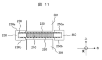
- FIG. 11 is a schematic diagram illustrating a cross section perpendicular to the front-rear direction of the periphery of the mover of the linear motor according to the third embodiment.
- the configuration described in the first and second embodiments can be adopted as the configuration of the third embodiment except for the following points.
- the magnetic cover 220 is disposed on the upper and lower surfaces of the magnetic pole frame 200 and the permanent magnet magnetic pole 210, and the magnetic cover 220 is sandwiched and fixed by the sandwiching member 250 and the magnetic pole frame 200 from the vertical direction.
- the permanent magnet magnetic pole 210 is fixed to the magnetic pole frame 200 by the magnetic cover 220 without coming off in the vertical direction.
- the sandwiching member 250 is a frame-side end mounting member provided at each of both end portions (both end portions) in the left-right direction of the magnetic pole frame 200.
- the sandwiching member 250 sandwiches and holds the magnetic cover 220 between the magnetic pole frame 200 and prevents the permanent magnet magnetic pole 210 from coming out of the gap (insertion portion) 200a.
- the clamping member 250, the magnetic cover 220, and the magnetic pole frame 200 are fixed using a tight fit such as press fit, shrink fit, or cool fit.
- the clamping member 250, the magnetic cover 220, and the magnetic pole frame 200 may be fitted with a clearance fit, and the clamping member 250 may be fixed to the magnetic pole frame 200 using screws or knock pins.
- any of the above-mentioned interference fits and screws or knock pins may be used in combination.
- the upper and lower surfaces of the clamping member 250 are used as guide rails that slide against the slide bearing or the rolling bearing. That is, rail surfaces are formed on the upper surface of the upper side portion 250a and the lower surface of the lower side portion 250b, respectively.
- the clamping member 250 is integrally formed (one member), and the distance between the upper guide rail surface and the lower guide rail surface of the clamping member 250 is the processing accuracy of the clamping member 250. Only affected. For this reason, the distance between the upper and lower guide rail surfaces can be kept highly accurate and constant. Thereby, in a present Example, the up-down direction position of the needle
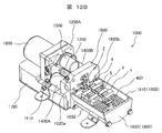
- FIG. 12A is a perspective view showing an embodiment (Example 4) of a compressor using a linear motor according to the present invention.
- 12B is a cross-sectional view showing a main part of the compressor of FIG. 12A.
- the compressor 1000 of the present embodiment can be used as a gas compressor that compresses air or refrigerant, and the other side of the armature 3 and the resonance spring 400 provided on one side of the armature 3 in the reciprocating direction of the mover 2.
- a piston (arranged in the piston 1200, not shown), a cylinder 1200, a solenoid valve 1400 (1400A, 1400B), an exhaust valve 1500, a dryer 1600, and an inverter 1700 are provided.
- the piston drive motor is a linear motor
- the mover 2 has a flat plate shape (flat plate shape). The mover 2 protrudes further rearward from the rear end of the end member 4.
- a casing 1800 that houses the armature 3 and the resonance spring 400 is attached to the cylinder 1200.
- the end member 4 is used as the front surface of the casing 1800, but a member constituting the front surface of the casing 1800 may be provided on the front side of the end member 4. That is, instead of using the end member 4 as the front member of the casing 1800, a front member may be provided separately from the end member 4.
- the casing 1800 has a cylindrical side surface (side surface member) 1810 and a rear surface (rear surface member, bottom surface member) 1820 configured separately, and the bottom surface 1820 is based on the cylinder 1200 by an insertion member 1830 extending forward and backward. It is fixed via a plate 1900. Accordingly, the side surface 1810 is sandwiched between the rear surface 1820 and the cylinder 1200.
- the electrode protrudes forward from the casing 1800 side, and the leading end of the winding 5 is electrically connected to one end of the electrode.
- the other end of the electrode passes through a through hole (not shown) formed in the base plate 1900, is inserted into the inverter 1700, and is electrically connected to the internal inverter circuit.
- the base plate 1900 is provided with a gas suction / discharge port 1910.
- two electromagnetic valves 1400A and 1400B are attached to the base 1900, and two through holes (gas passages) 1920a and 1920b through which gas flows are provided corresponding to the electromagnetic valves 1400A and 1400B.
- the electromagnetic valves 1400A and 1400B are three-way valves and constitute gas suction and discharge valves.
- one solenoid valve 1400A is in the suction state
- the other solenoid valve 1400b is in the discharge state.
- One solenoid valve 1400A causes the gas sucked from the suction discharge port 1910 to flow into the casing 1800 through the through hole 1920a in the suction state.
- the other solenoid valve 1400B is in a discharge state, and blocks the flow of gas through the through hole 1920b.
- the gas that has flowed into the casing 1800 through the electromagnetic valve 1400A flows through the gap between the mover 2, the end member 4 and the base plate 1900, flows into the cylinder 1200, and flows into the dryer 1600 through the cylinder 1200. Further, the gas is discharged from the dryer 1600 through the other electromagnetic valve 1400B.
- the suction and discharge states of the solenoid valve 1400A and the solenoid valve 1400B are switched, the gas flow follows the reverse of the above-described path.
- the cylinder 1200 compresses the gas that flows in as necessary.
- a suction / discharge port (not shown) is provided at a position corresponding to the suction / discharge port 1910 on the side of the base plate 1900 where the through hole 1920b is provided.
- the dryer 1600 is attached to the cylinder head 1200A of the cylinder 1200 so as to communicate with the inside of the cylinder 1200.
- FIG. 13 is a configuration diagram of the refrigerator according to the fifth embodiment.
- the refrigerator 2001 is provided with a double-folded refrigerating compartment door 2002a on the front side of the refrigerating room 2002, on the front side of the ice making room 2003, the upper freezing room 2004, the lower freezing room 2005, and the vegetable room 2006.
- a drawer-type ice making room door 2003a is provided with a drawer-type ice making room door 2003a, an upper freezer compartment door 2004a, a lower freezer compartment door 2005a, and a vegetable compartment door 2006a.
- a machine room 2020 is provided on the back side of the vegetable room 2006, and a compressor 2024 is disposed in the machine room 2020.
- An evaporator chamber 2008 is provided on the back side of the ice making chamber 2003, the upper freezer chamber 2004, and the lower freezer chamber 2005, and the evaporator 2007 is provided in the evaporator chamber 2008.
- a radiator not shown
- a capillary tube as a decompression means, a three-way valve, and the like are connected by a refrigerant pipe to form a refrigeration cycle 2030.
- the linear motor 100 according to any one of the above-described embodiments is adopted as the compressor 2024 constituting the refrigeration cycle 2030 of the refrigerator 2001.
- the compressor 1000 of the fifth embodiment may be adopted as the compressor 2024.
- the enlargement of the compressor 2024 constituting the refrigeration cycle 2030 can be suppressed.
- a large space can be secured for the refrigerator compartment and the freezer compartment, and a large-capacity refrigerator can be provided without increasing the external dimensions.
- FIG. 14 is a configuration diagram of a vehicle air suspension according to the sixth embodiment.
- the vehicle body 3002 constitutes the body of the vehicle 3001. A total of four wheels 3003 including left and right front wheels and left and right rear wheels are provided below the vehicle body 3002.
- the air suspension 3004 includes four air springs 3005 provided between the vehicle body 3002 and each wheel 3003, an air compressor 3006, a valve unit 3008, and a controller 3011. The air suspension 3004 adjusts the vehicle height by supplying and discharging compressed air from the air compressor 3006 to each air spring 3005.
- the linear motor 100 of any of the above-described embodiments is employed as the drive motor for the air compressor 3006.
- the compressor 1000 of the fifth embodiment may be adopted as the air compressor 3006.
- the air compressor 3006 is connected to the valve unit 3008 through a supply / discharge pipe (pipe) 3007.
- the valve unit 3008 is provided with four supply / discharge valves 3008a made up of electromagnetic valves, which are provided for each wheel 3003.
- a branch pipe (pipe) 3009 is provided between the valve unit 3008 and the air spring 3005 of each wheel 3003.
- the air spring 3005 is connected to the air compressor 3006 via a branch pipe line 3009, a valve 3008a, and a supply / discharge pipe line 3007.
- the valve unit 3008 opens and closes the supply / discharge valve 3008a in accordance with a signal from the controller 3011 to supply / discharge compressed air to / from each air spring 3005 to adjust the vehicle height.
- the size of the air compressor 3006 constituting the air suspension 3004 can be suppressed.
- a space for mounting the air compressor 3006 in the vehicle 3001 can be reduced, and the degree of freedom of arrangement of the air compressor 3006 is increased.
- the moving magnet type in which the armature 3 is fixed and the field element (movable element 2) moves is illustrated, but a moving coil type in which the field element is fixed and the armature 3 is moved may be used.
- the mover 2 instead of providing the magnetic pole teeth 301 in the vertical direction of the mover 2, a configuration may be adopted in which the mover 2 is provided on one side in the vertical direction.
- the arm 302 can support the core 300 with one end contacting the floor surface of the soft magnetic material.
- the magnetic pole teeth 301 and the arm portion 302 may be configured by laminating amorphous metal or may be configured by a dust core.
- amorphous metal When an amorphous metal is used, there is an effect of reducing iron loss generated in the magnetic pole teeth 301 and the arm portion 302, and when a dust core is used, it can be configured in an arbitrary shape three-dimensionally.
- the present invention can be applied to various devices that move the stator 1 and the mover 2 relative to each other in addition to the motor (linear motor). For example, the same effect can be obtained even when used for a generator, a compressor, an electromagnetic suspension, a positioning device, or the like.
- this invention is not limited to each above-mentioned Example, Various modifications are included.
- the above-described embodiments have been described in detail for easy understanding of the present invention, and are not necessarily limited to those having all the configurations.
- a part of the configuration of one embodiment can be replaced with the configuration of another embodiment, and the configuration of another embodiment can be added to the configuration of one embodiment.
Landscapes
- Engineering & Computer Science (AREA)
- Physics & Mathematics (AREA)
- Chemical & Material Sciences (AREA)
- Combustion & Propulsion (AREA)
- Electromagnetism (AREA)
- Power Engineering (AREA)
- Linear Motors (AREA)
Abstract
本発明は、磁気特性の低下を抑え、かつ永久磁石の減磁耐力を向上させる界磁子を有するリニアモータを提案する。界磁子2と、界磁子2を挟んで設けられた複数の電機子磁極301と、を有し、界磁子2と電機子磁極301とが相対変位するリニアモータ100において、界磁子2は、界磁子2と電機子磁極301とが相対変位する方向に沿って配列された複数の永久磁石磁極210と、永久磁石磁極210を囲む縁部を有し永久磁石磁極210を支持する磁極フレーム200と、永久磁石磁極210の電機子磁極301との対向面に接するようにして設けられた磁性体220と、を有し、磁性体220は、前記縁部を越えて磁極フレーム200まで延出している。
Description
本発明は、リニアモータに関する。
推力発生機構を有するリニアモータは、回転機を直線状に切り開いた形状をしており、固定子と可動子の各々に構成された磁極の間に働く磁力によって、可動子に推力を発生させる。本技術分野の背景技術として、WO2014/064785A1(特許文献1)及びWO2011/155022A1(特許文献2)に記載されたリニアモータが知られている。
特許文献1のリニアモータでは、磁石保持部材の複数の磁石保持穴に永久磁石を固着して構成している(図31参照)。
特許文献2のリニアモータでは、永久磁石の上面及び下面のそれぞれに高透磁率部材が接着剤等を用いて設置されている(段落0021、図3Aおよび図3B参照)。
特許文献1のリニアモータは、磁石保持部材に永久磁石が接着され、永久磁石の両側に空隙を介して電機子磁極が対向配置されている。そのため、永久磁石が電機子磁極から受ける逆磁界の影響が大きく、永久磁石が減磁しやすい。
特許文献2のリニアモータは、磁石量を低減しつつ可動子(界磁子)の剛性を高めてたわみにくくするために、永久磁石の上面及び下面のそれぞれに高透磁率部材を設置している。文献中には開示されていないが、永久磁石と電機子磁極との間に高透磁率部材が設置されることで、永久磁石が電機子磁極から受ける逆磁界の影響を抑制し、減磁耐力を向上できる。しかし、高透磁率部材の表面積は永久磁石と同等以下であるため、高透磁率部材を永久磁石の表面に設置するために接着剤が用いられ、両者の間には接着層が少なからず存在する。この接着層は磁気回路における磁気抵抗となり、リニアモータの磁気特性ならびに推力特性を低下させる可能性がある。
本発明の目的は、磁気特性の低下を抑え、かつ永久磁石の減磁耐力を向上させる界磁子を有するリニアモータを提案することにある。
上記目的を達成するために、本発明のリニアモータは、
界磁子と、前記界磁子を挟んで設けられた複数の電機子磁極と、を有し、前記界磁子と前記電機子磁極とが相対変位するリニアモータにおいて、
前記界磁子は、前記界磁子と前記電機子磁極とが相対変位する方向に沿って配列された複数の永久磁石磁極と、前記永久磁石磁極を囲む縁部を有し前記永久磁石磁極を支持する磁極フレームと、前記永久磁石磁極の前記電機子磁極との対向面に接するようにして設けられた磁性体と、を有し、
前記磁性体は、前記縁部を越えて前記磁極フレームまで延出している。
界磁子と、前記界磁子を挟んで設けられた複数の電機子磁極と、を有し、前記界磁子と前記電機子磁極とが相対変位するリニアモータにおいて、
前記界磁子は、前記界磁子と前記電機子磁極とが相対変位する方向に沿って配列された複数の永久磁石磁極と、前記永久磁石磁極を囲む縁部を有し前記永久磁石磁極を支持する磁極フレームと、前記永久磁石磁極の前記電機子磁極との対向面に接するようにして設けられた磁性体と、を有し、
前記磁性体は、前記縁部を越えて前記磁極フレームまで延出している。
本発明によれば、磁気特性の低下を抑え、かつ永久磁石の減磁耐力を向上させる界磁子を有するリニアモータを提供することができる。上記した以外の課題、構成及び効果は、以下の実施形態の説明により明らかにされる。
以下、本発明の実施例を、添付の図面を参照しつつ詳細に説明する。複数の実施例及び各実施例の変更例において、同様の構成要素には同様の符号を付し、説明を省略する。説明のため、互いに直交する前後、左右、及び上下方向という語を用いるが、必ずしも重力方向は下向きである必要はなく、上、右、左、前若しくは後方向又はそれ以外の方向に平行にできる。
なお、以下で説明する各実施例及び各変更例では、前後方向は可動子2の駆動方向に一致し、上下方向は永久磁石磁極210の磁極面(S,N極が生じる面)に垂直な方向に一致する。また、可動子2は前後方向を長手方向としており、左右方向を可動子2の幅方向と呼んで説明する場合がある。或いは、可動子2の移動方向(前後方向)に沿う方向を第1方向、第1方向に垂直な界磁子の幅方向(左右方向)に沿う方向を第2方向、第1方向及び第2方向に垂直な界磁子の厚さ方向(上下方向)に沿う方向を第3方向として説明する場合もある。
[実施例1]
図1乃至図4を参照して、本発明の実施例1に係るリニアモータについて、説明する。
図1は、実施例1に係るリニアモータの斜視図である。図2は、実施例1に係るリニアモータの左右方向に対して垂直な断面を示す斜視図である。図3は、実施例1に係るリニアモータの可動子の左右方向に対して垂直な断面図である。図4は、実施例1に係るリニアモータの可動子の上方向から見た図である。
図1乃至図4を参照して、本発明の実施例1に係るリニアモータについて、説明する。
図1は、実施例1に係るリニアモータの斜視図である。図2は、実施例1に係るリニアモータの左右方向に対して垂直な断面を示す斜視図である。図3は、実施例1に係るリニアモータの可動子の左右方向に対して垂直な断面図である。図4は、実施例1に係るリニアモータの可動子の上方向から見た図である。
リニアモータ100は、固定子1及び可動子2からなる。以降の説明では、電機子側を地面に対して静止させる固定子、界磁子側を地面に対して前後方向に移動させる可動子として説明するが、固定子と可動子とは逆の関係であっても良い。すなわちリニアモータ100は、界磁子と電機子(電機子磁極)とが相対変位するように構成される。
≪固定子1≫
固定子1は、電機子3と、電機子3の前側及び後側それぞれに配置された端部部材4と、巻線5と、を備える。電機子3は、軟磁性体のコア300及びスペーサ310を有し、複数のコア300は軟磁性体のスペーサ310で繋いで構成されている。これにより、複数のコア300及びスペーサ310を含む磁路を形成できるようにしている。コア300には上下に磁極歯(電機子磁極)301があり、それぞれ巻線5が巻回されている。
固定子1は、電機子3と、電機子3の前側及び後側それぞれに配置された端部部材4と、巻線5と、を備える。電機子3は、軟磁性体のコア300及びスペーサ310を有し、複数のコア300は軟磁性体のスペーサ310で繋いで構成されている。これにより、複数のコア300及びスペーサ310を含む磁路を形成できるようにしている。コア300には上下に磁極歯(電機子磁極)301があり、それぞれ巻線5が巻回されている。
電機子3は、1つ又は2つ以上を前後方向に並べることができる。また、端部部材4は、最も前側の電機子3の前側及び/又は最も後側の電機子3の後側に設けることができる。
≪コア300≫
コア300は、可動子2を挟んで対向配置された磁極歯301と、これら2つの磁極歯301をつなぐ腕部302とを有する。磁極歯301及び腕部302は、例えば、電磁鋼板を前後方向に積層して構成できる。磁極歯301には巻線5を巻回している。
コア300は、可動子2を挟んで対向配置された磁極歯301と、これら2つの磁極歯301をつなぐ腕部302とを有する。磁極歯301及び腕部302は、例えば、電磁鋼板を前後方向に積層して構成できる。磁極歯301には巻線5を巻回している。
腕部302は、巻線5及び可動子2の左右方向における両外側を上下方向に延設された軟磁性体であり、永久磁石磁極210から発せられ、磁極歯301に進入した磁束を、この磁極歯301に可動子2を介して対向する別の磁極歯301に導くことができる。これにより、コア300は、磁極歯301と、この磁極歯301に対向する永久磁石磁極210と、この永久磁石磁極210に前述の磁極歯301が対向する側とは反対側の面で対向する磁極歯301と、腕部302と、を含む磁路を形成できる。
≪スペーサ310≫
スペーサ310は、隣接するコア300を流れる磁束を通過させることができる。スペーサ310は、例えば、電磁鋼板を前後方向に積層して構成できる。このため、2つのコア300の間にスペーサ310を配した電機子3は、永久磁石磁極210の前後方向間隔等の設計に応じて、隣り合う2つのコア300及び永久磁石磁極210を含む磁路を形成できる。
スペーサ310は、隣接するコア300を流れる磁束を通過させることができる。スペーサ310は、例えば、電磁鋼板を前後方向に積層して構成できる。このため、2つのコア300の間にスペーサ310を配した電機子3は、永久磁石磁極210の前後方向間隔等の設計に応じて、隣り合う2つのコア300及び永久磁石磁極210を含む磁路を形成できる。
≪端部部材4≫
端部部材4は、軟磁性体又は非磁性体で形成することができる。端部部材4は、前後方向に延在する貫通ボルト等(図示せず)の固定部材により、コア300及びスペーサ310とともに固定されている。また、端部部材4には図示しない軸受等の支持部材が配置され、可動子2を支持している。
端部部材4は、軟磁性体又は非磁性体で形成することができる。端部部材4は、前後方向に延在する貫通ボルト等(図示せず)の固定部材により、コア300及びスペーサ310とともに固定されている。また、端部部材4には図示しない軸受等の支持部材が配置され、可動子2を支持している。
≪可動子2≫
可動子2は、前後方向を長手方向としている。可動子2は、前後方向に複数の永久磁石を固定する非磁性体または軟磁性体からなる磁極フレーム200と、磁極フレーム200に設けられた永久磁石磁極210と、永久磁石磁極210及び磁極フレーム200の上側及び下側に配置された磁性カバー220を有している。本実施例の可動子2は、永久磁石磁極210を3個固定した態様である。複数の永久磁石磁極210は、界磁子により構成される可動子2と電機子磁極301により構成される固定子1とが相対変位する方向に沿って配列される。永久磁石磁極210は、3個以上でも以下でも良い。永久磁石磁極210はそれぞれ上下方向に磁化され、隣り合う磁極210の上面は、N極とS極とが、交互になるように配されている。
可動子2は、前後方向を長手方向としている。可動子2は、前後方向に複数の永久磁石を固定する非磁性体または軟磁性体からなる磁極フレーム200と、磁極フレーム200に設けられた永久磁石磁極210と、永久磁石磁極210及び磁極フレーム200の上側及び下側に配置された磁性カバー220を有している。本実施例の可動子2は、永久磁石磁極210を3個固定した態様である。複数の永久磁石磁極210は、界磁子により構成される可動子2と電機子磁極301により構成される固定子1とが相対変位する方向に沿って配列される。永久磁石磁極210は、3個以上でも以下でも良い。永久磁石磁極210はそれぞれ上下方向に磁化され、隣り合う磁極210の上面は、N極とS極とが、交互になるように配されている。
また、可動子2は、上下方向において2つの磁極歯301の間、かつ左右方向において2つの腕部302の間の空間に配されている。なお、永久磁石磁極210は上下方向に垂直な平板形状にできる。すなわち本実施例では、永久磁石磁極210は、上下方向の厚み寸法に対して左右方向の幅寸法及び前後方向の長さ寸法が大きい平板形状である。本実施例では、上下方向とは、磁極歯301と永久磁石磁極210の極性とが対向している方向である。
なお、上述したように、本実施例では、可動子2は界磁子によって構成される。
≪磁極フレーム200≫
磁極フレーム200は、永久磁石磁極210を嵌装する空隙200aを複数備えたはしご状にすることができる。永久磁石磁極210は空隙200aに嵌入されることで、左右方向及び前後方向に抜けることなく、磁極フレーム200に固定される。磁極フレーム200は、永久磁石磁極を囲む、空隙200aの縁部を有し、永久磁石磁極210を支持する。
磁極フレーム200は、永久磁石磁極210を嵌装する空隙200aを複数備えたはしご状にすることができる。永久磁石磁極210は空隙200aに嵌入されることで、左右方向及び前後方向に抜けることなく、磁極フレーム200に固定される。磁極フレーム200は、永久磁石磁極を囲む、空隙200aの縁部を有し、永久磁石磁極210を支持する。
空隙200aは磁極フレーム200を上下方向に貫通する貫通孔として形成されており、永久磁石磁極210が上下方向に嵌入される嵌入部を構成する。永久磁石磁極210は空隙(嵌入部)200aを埋めるように空隙(嵌入部)200aに配置されることで、左右方向及び前後方向への位置ずれが防止される。磁極フレーム200は、軟磁性体で形成しても良いし、非磁性体で形成しても良い。
なお、空隙(嵌入部)200aは、永久磁石磁極210を貼付できる凹部で構成しても良い。この凹部は上下方向における磁極フレーム200の一端面に凹状に形成される。この凹部も永久磁石磁極210が嵌入される空隙(嵌入部)200aの一種とみなすことができる。
≪永久磁石磁極210≫
永久磁石磁極210は、ネオジム磁石等の希土類磁石で構成してもよいし、フェライト磁石等、他の素材による永久磁石を用いてもよい。
永久磁石磁極210は、ネオジム磁石等の希土類磁石で構成してもよいし、フェライト磁石等、他の素材による永久磁石を用いてもよい。
≪磁性カバー220≫
磁性カバー220は、可動子2の上下方向の表面にあって、永久磁石磁極210の上下方向の表面のみならず、磁極フレーム200の上下方向表面まで延出され、磁極フレーム200及び永久磁石磁極210の両方の上面及び下面で各々接するように設けられている。すなわち磁性カバー220は、永久磁石磁極210の電機子磁極301との対向面に接するようにして、磁極フレーム200の永久磁石磁極210を囲む空隙200aの縁部を越えて磁極フレーム200まで延出している。
磁性カバー220は、可動子2の上下方向の表面にあって、永久磁石磁極210の上下方向の表面のみならず、磁極フレーム200の上下方向表面まで延出され、磁極フレーム200及び永久磁石磁極210の両方の上面及び下面で各々接するように設けられている。すなわち磁性カバー220は、永久磁石磁極210の電機子磁極301との対向面に接するようにして、磁極フレーム200の永久磁石磁極210を囲む空隙200aの縁部を越えて磁極フレーム200まで延出している。
磁性カバー220は、磁性体で構成される。磁性カバー220は、例えば、鉄を含む鉄系材料又は磁性を有するステンレスや電磁鋼板等の薄板で構成してもよいし、アモルファス金属や圧粉磁心で構成してもよい。
≪リニアモータ100の減磁特性≫
図5は、本発明との比較例(第1比較例)について、永久磁石磁極の不可逆減磁部位の分布を示す図である。図5では、磁極フレームは図示していない。
図5は、本発明との比較例(第1比較例)について、永久磁石磁極の不可逆減磁部位の分布を示す図である。図5では、磁極フレームは図示していない。
第1比較例では、実施例1における磁性カバー220が設けられておらず、可動子2が磁極フレーム200と永久磁石磁極210のみで構成されている。図5の色の濃い部分が不可逆減磁を起こしている部位(不可逆減磁部位210a)である。不可逆減磁とは、温度や外部磁界の影響で永久磁石の磁力が不可逆的に弱まる現象であり、リニアモータ100の推力が低下することを意味する。図5において、各永久磁石磁極210の中央部の色が濃くなっており、当該部位で不可逆減磁を起こしている。
図6は、本発明との比較例(第2比較例)について、永久磁石磁極の不可逆減磁部位の分布を示す図である。図6では、磁極フレームは図示していない。
第2比較例では、可動子2が磁極フレーム200と永久磁石磁極210と磁性体230とで構成され、磁性体230が永久磁石磁極210の表面に配置されている。しかし第2比較例では、磁性カバー230が永久磁石磁極210の表面のみを覆っている。図6において、各永久磁石磁極210の角部(端部)の色が濃くなっている。第2比較例では、第1比較例に対して不可逆減磁を起こしている部位は小さくなっているものの、永久磁石磁極210の角部で不可逆減磁を起こしている。
図7は、実施例1の構成における、永久磁石磁極の不可逆減磁部位の分布を示す図である。図7では、磁極フレームは図示していない。
実施例1では、可動子2が磁極フレーム200と永久磁石磁極210と磁性カバー220とで構成されている。実施例1では、磁性カバー220が永久磁石磁極210の上下方向の表面(端面)のみならず、磁極フレーム200の上下方向表面まで延出されている。
すなわち磁性カバー220は、永久磁石磁極210の周縁から外側にはみ出すように設けられている。図7において、各永久磁石磁極210に色の濃い部分はなく、不可逆減磁を起こしていない。
すなわち磁性カバー220は、永久磁石磁極210の周縁から外側にはみ出すように設けられている。図7において、各永久磁石磁極210に色の濃い部分はなく、不可逆減磁を起こしていない。
以上より、本実施例の構成により、永久磁石磁極の減磁耐力を向上させ、不可逆減磁に伴うリニアモータ100の推力低下を抑制することができることが分かる。
上述したように、空隙200aを凹部で構成し、磁極フレーム200を非磁性体で構成する場合、磁性カバー220は永久磁石磁極210の一端面に設けられ、永久磁石磁極210の他端面は非磁性体で覆われることになる。このような構成であっても、永久磁石磁極210の減磁耐力を向上する効果や、不可逆減磁に伴うリニアモータ100の推力低下を抑制する効果が得られる。従って、空隙200aを貫通孔で構成する場合に、永久磁石磁極210の上下方向における片方の端面に磁性カバー220を設けるだけでも、永久磁石磁極210の減磁耐力を向上する効果や、不可逆減磁に伴うリニアモータ100の推力低下を抑制する効果が得られる。減磁耐力の向上効果及び推力低下の抑制効果を高めるためには、永久磁石磁極210の上下方向における両端面に磁性カバー220を設けることが好ましい。
≪磁性カバー220の固定構造≫
図8は、実施例1における、可動子に磁性カバーを固定する構造を示す斜視図である。
ねじ穴200bを持つ磁極フレーム200の空隙(嵌入部)200aに永久磁石磁極210を嵌入後、空孔220aを持つ磁性カバー220を可動子2の上面にかぶせて、ねじ240を用いて磁性カバー220を磁極フレーム200に締結する。
図8は、実施例1における、可動子に磁性カバーを固定する構造を示す斜視図である。
ねじ穴200bを持つ磁極フレーム200の空隙(嵌入部)200aに永久磁石磁極210を嵌入後、空孔220aを持つ磁性カバー220を可動子2の上面にかぶせて、ねじ240を用いて磁性カバー220を磁極フレーム200に締結する。
本実施例では、磁性カバー220が磁極フレーム200の上下方向表面まで延出されているため、永久磁石磁極210の外側にねじ穴200bを設けることができる。ねじ穴200bは、左右方向において、永久磁石磁極210の外側の磁極フレーム200の部分に設けているが、前後方向において、永久磁石磁極210の外側の磁極フレーム200の部分に設けてもよい。すなわち、隣接する永久磁石磁極210の間に介在する磁極フレーム200の部分に設けてもよい。
磁性カバー220を磁極フレーム200の上下方向表面まで延出させる場合、永久磁石磁極210に対して左右方向に延出させてもよいし、前後方向に延出させてもよいし、左右方向及び前後方向の両方に延出させてもよい。すなわち、磁性カバー220は永久磁石磁極210に対して少なくとも左右方向又は前後方向のいずれか一方に延出させればよい。
磁性カバー220は、磁極フレーム200を補強する部材としても利用することができる。この場合、磁性カバー220は左右方向及び前後方向の両方に延出することにより、磁極フレーム200を補強する効果が高まる。また、磁性カバー220は左右方向及び前後方向の両方に延出することにより、永久磁石磁極の減磁耐力を向上させ、不可逆減磁に伴うリニアモータ100の推力低下を抑制する効果が高まる。
なお図8は、可動子2の上側のみについて図示しているが、可動子2の下側にも同様の方法で固定することができる。
本実施例では、可動子2の下側に磁性カバー220を固定して、空隙200aに永久磁石磁極210を嵌入する。このとき空隙200aの下側には磁性カバー220が設けられているため、空隙200aに嵌入された永久磁石磁極210を空隙200a内に支持することができる。その後、磁性カバー220を可動子2の上面にかぶせて、永久磁石磁極210を空隙200a内に保持する。これにより、可動子2を簡単に組み立てることができる。
磁性カバー220は永久磁石磁極210毎に分割された構成であってもよく、複数の永久磁石磁極210に対応する磁性カバーを含んで磁性カバー220が複数に分割される構成であってもよい。
本実施例では、可動子2の上側に設けられる磁性カバー220及び可動子2の下側に設けられる磁性カバー220がそれぞれ1つの部材で構成される。すなわち磁性カバー(磁性体)220は、可動子(界磁子)2の第3方向(上下方向)における両端面(上面及び下面)のそれぞれに設けられ、可動子2の各端面に設けられる磁性カバー220のそれぞれが全ての永久磁石磁極210を覆う一枚のカバー部材として構成される。これにより、本実施例のリニアモータ100は、組立工数を少なくして簡単に可動子2を組み立てることができる。
[実施例2]
図9乃至図10を参照して、磁性カバー220の固定構造について説明する。
図9乃至図10を参照して、磁性カバー220の固定構造について説明する。
図9は、本発明との比較例(第3比較例)のリニアモータの可動子について、左右方向に対して垂直な断面を示す概略図である。磁極フレーム200’の上下方向の厚さは、永久磁石磁極210’の上下方向の厚さよりも厚く、永久磁石磁極210’の上面及び下面に磁性体230が接着剤240を介して固定されている。接着剤240で接着された永久磁石磁極210’及び磁性体230は磁極フレーム200に嵌入され、接着剤240を介して磁極フレーム200に固定されている。
なお、第3比較例においても第2比較例と同様に、磁性カバー230は永久磁石磁極210’の表面のみを覆っている。
ここで、可動子2’の上下方向の厚さをT、永久磁石磁極210’の上下方向の厚さをTm1、接着剤240の上下方向の厚さをTa、磁性体230の上下方向の厚さをTbとすると、Tm1は以下のようになる。
Tm1=T-2×(Ta+Tb) …(数1)
また、磁極フレーム200’の空隙(嵌入部)200a’の前後方向の長さをL、永久磁石磁極210’の前後方向の長さをLm1、接着剤240の前後方向の長さをLaとすると、Lm1は以下のようになる。
Lm1=L-2×La …(数2)
上述した(数2)及び(数3)は第3比較例に関する数式である。
Tm1=T-2×(Ta+Tb) …(数1)
また、磁極フレーム200’の空隙(嵌入部)200a’の前後方向の長さをL、永久磁石磁極210’の前後方向の長さをLm1、接着剤240の前後方向の長さをLaとすると、Lm1は以下のようになる。
Lm1=L-2×La …(数2)
上述した(数2)及び(数3)は第3比較例に関する数式である。
図10は、実施例2に係るリニアモータの可動子について、左右方向に対して垂直な断面を示す概略図である。
実施例2の構成は、以下の点を除き実施例1で説明した構成を採用することができる。
磁極フレーム200の上下方向の厚さは、永久磁石磁極210の上下方向の厚さよりも薄く、永久磁石磁極210が磁極フレーム200から上下方向にはみ出すようにして磁極フレーム200に嵌入されている。磁性カバー220は磁極フレーム200の上面及び下面に接着剤240を介して固定され、永久磁石磁極210の上面及び下面とは直接接している。永久磁石磁極210は上面及び下面の磁性カバー220によって、上下方向に動かないよう固定されている。
磁極フレーム200の上下方向の厚さは、永久磁石磁極210の上下方向の厚さよりも薄く、永久磁石磁極210が磁極フレーム200から上下方向にはみ出すようにして磁極フレーム200に嵌入されている。磁性カバー220は磁極フレーム200の上面及び下面に接着剤240を介して固定され、永久磁石磁極210の上面及び下面とは直接接している。永久磁石磁極210は上面及び下面の磁性カバー220によって、上下方向に動かないよう固定されている。
ここで、可動子2の厚さをT、永久磁石磁極210の厚さをTm2、磁性カバー220の厚さをTbとすると、Tm2は以下のようになる。
Tm2=T-2×Tb …(数3)
また、磁極フレーム200の空隙(嵌入部)200aの前後方向の長さをL、永久磁石磁極210の前後方向の長さをLm2とすると、Lm2は以下のようになる。
Lm2=L …(数4)
上述した(数3)及び(数4)は実施例2に関する数式である。
Tm2=T-2×Tb …(数3)
また、磁極フレーム200の空隙(嵌入部)200aの前後方向の長さをL、永久磁石磁極210の前後方向の長さをLm2とすると、Lm2は以下のようになる。
Lm2=L …(数4)
上述した(数3)及び(数4)は実施例2に関する数式である。
(数1)及び(数3)より、Tm1とTm2との関係は以下のようになる。
Tm2>Tm1 …(数5)
すなわち、実施例2の構成により、第3比較例の構成と比べて永久磁石磁極210の上下方向の厚さを厚くすることができる。その結果、実施例2の方が永久磁石磁極210の減磁耐力を向上させられるとともに、リニアモータの推力も向上できる。
Tm2>Tm1 …(数5)
すなわち、実施例2の構成により、第3比較例の構成と比べて永久磁石磁極210の上下方向の厚さを厚くすることができる。その結果、実施例2の方が永久磁石磁極210の減磁耐力を向上させられるとともに、リニアモータの推力も向上できる。
(数2)及び(数4)より、Lm1とLm2の関係は以下のようになる。
Lm2>Lm1 …(数6)
すなわち、実施例2の構成により、第3比較例の構成と比べて永久磁石磁極210の前後方向の長さを長くすることができる。その結果、実施例2の方がリニアモータの推力を向上できる。
Lm2>Lm1 …(数6)
すなわち、実施例2の構成により、第3比較例の構成と比べて永久磁石磁極210の前後方向の長さを長くすることができる。その結果、実施例2の方がリニアモータの推力を向上できる。
[実施例3]
図11を参照して、磁性カバー220の固定構造について説明する。
図11を参照して、磁性カバー220の固定構造について説明する。
図11は、実施例3に係るリニアモータの可動子周辺部について、前後方向に対して垂直な断面を示す概略図である。実施例3の構成は、以下の点を除き実施例1及び2で説明した構成を採用することができる。
磁極フレーム200と永久磁石磁極210の上面及び下面に磁性カバー220が配置され、磁性カバー220は挟持部材250と磁極フレーム200とにより上下方向から挟まれて固定されている。磁性カバー220により、永久磁石磁極210が上下方向に抜けることなく磁極フレーム200に固定される。
挟持部材250は、磁極フレーム200の左右方向における両端部(両側端部)のそれぞれに設けられるフレーム側端部取付部材である。挟持部材250は、磁性カバー220を磁極フレーム200との間に挟み込んで保持して、永久磁石磁極210の空隙(嵌入部)200aからの抜けを防止する。
挟持部材250と磁性カバー220及び磁極フレーム200とは圧入や焼きばめ、又は冷しばめなど、締めしろのある締りばめを用いて、固定する。あるいは、挟持部材250と磁性カバー220及び磁極フレーム200とをすきまばめで嵌め合い、ねじ又はノックピンを用いて挟持部材250を磁極フレーム200に固定してもよい。あるいは、上述したいずれかの締りばめと、ねじ又はノックピンと、を併用してもよい。
本実施例では、挟持部材250の上下面をすべり軸受または転がり軸受と対向して摺動するガイドレールとして用いる。すなわち、挟持部材250の上辺部250aの上面と下辺部250bの下面とにそれぞれレール面が形成されている。挟持部材250でガイドレールを構成することにより、他にガイドレール部品を設ける必要が無くなり、部品点数及び組立工数を削減することができる。
さらに本実施例では、挟持部材250が一体(一つの部材)で構成されており、挟持部材250の上側のガイドレール面と下側のガイドレール面との間の距離は挟持部材250の加工精度のみの影響を受ける。このため、上下のガイドレール面間距離を高精度かつ一定に保つことができる。これにより本実施例では、可動子2の上下方向位置を精度よく配することができる。そのため、軸受における摺動損失を低減し、リニアモータを高効率に駆動できる。
[実施例4]
図12Aは、本発明に係るリニアモータを用いた圧縮機の実施例(実施例4)を示す斜視図である。図12Bは、図12Aの圧縮機の要部を示す断面図である。
図12Aは、本発明に係るリニアモータを用いた圧縮機の実施例(実施例4)を示す斜視図である。図12Bは、図12Aの圧縮機の要部を示す断面図である。
本実施例の圧縮機1000は、空気や冷媒を圧縮する気体圧縮機として用いることができ、可動子2の往復動方向について電機子3の一方側に設けた共振ばね400及び電機子3の他方側に設けたピストン(ピストン1200内に配置、図示せず)と、シリンダ1200と、電磁弁1400(1400A,1400B)と、排気弁1500と、ドライヤ1600と、及びインバータ1700と、を有する。
本実施例の圧縮機1000では、ピストンの駆動モータがリニアモータで構成されており、可動子2が扁平な板状(平板状)を成している。また、可動子2は端部部材4の後側端部から更に後方に突き出している。
シリンダ1200には、電機子3及び共振ばね400を収納するケーシング1800が取付けられている。本実施例では、ケーシング1800の前面として端部部材4を用いているが、端部部材4の前側にケーシング1800の前面を構成する部材を設けても良い。
すなわち、端部部材4をケーシング1800の前面部材として兼用する代わりに、端部部材4とは別に前面部材を設けてもよい。
すなわち、端部部材4をケーシング1800の前面部材として兼用する代わりに、端部部材4とは別に前面部材を設けてもよい。
ケーシング1800は、筒状の側面(側面部材)1810と後面(後面部材、底面部材)1820とが別体で構成されており、前後に延在する挿通部材1830によって、底面1820がシリンダ1200にベース板1900を介して固定されている。これにより、側面1810は後面1820及びシリンダ1200に挟持されている。
ケーシング1800側から前方に向けて電極が突出し、電極の一端部に巻線5の引き出し端部が電気的に接続されている。電極の他端部はベース板1900に形成された貫通孔(図示せず)を貫通してインバータ1700の内部に挿入され、内部のインバータ回路と電気的に接続されている。
ベース板1900にはガスの吸入吐出口1910が設けられている。また、ベース1900には2つの電磁弁1400A,1400Bが取り付けられ、各電磁弁1400A,1400Bに対応してガスが流れる2つの貫通孔(ガス通路)1920a,1920bが設けられている。電磁弁1400A,1400Bは三方弁であり、ガスの吸入吐出弁を構成する。一方の電磁弁1400Aが吸入状態にある場合、他方の電磁弁1400bは吐出状態となる。一方の電磁弁1400Aは吸入状態において吸入吐出口1910から吸入したガスを、貫通孔1920aを通じてケーシング1800の内部に流す。このとき、他方の電磁弁1400Bは吐出状態になっており、貫通孔1920bを通じたガスの流れを遮断する。
電磁弁1400Aを通じてケーシング1800の内部に流入したガスは、可動子2と端部部材4及びベース板1900との隙間を流れてシリンダ1200の内部に流れ、シリンダ1200を通じてドライヤ1600に流れる。更に、ガスはドライヤ1600からもう一方の電磁弁1400Bを通じて吐出される。電磁弁1400A及び電磁弁1400Bの吸入吐出の状態が入れ替わると、ガスの流れは上述した経路の逆を辿って流れる。シリンダ1200では必要に応じて流入したガスの圧縮を行う。ベース板1900の貫通孔1920bが設けられた側には、吸入吐出口1910に対応する位置に、図示しない吸入吐出口が設けられている。
シリンダ1200のシリンダヘッド1200Aには、ドライヤ1600がシリンダ1200の内部と連通可能な状態で取り付けられている。
[実施例5]
図13は、実施例5に係る冷蔵庫の構成図である。
図13は、実施例5に係る冷蔵庫の構成図である。
冷蔵庫2001は、冷蔵室2002の前面側に左右に分割された観音開きの冷蔵室扉2002aを備え、製氷室2003と、上段冷凍室2004と、下段冷凍室2005と、野菜室2006との前面側に、それぞれ引き出し式の製氷室扉2003a、上段冷凍室扉2004a、下段冷凍室扉2005a、野菜室扉2006aを備えている。
野菜室2006の背面側には、機械室2020が設けられ、機械室2020に圧縮機2024が配置されている。また、製氷室2003、上段冷凍室2004、及び下段冷凍室2005の背面側には、蒸発器室2008が設けられ、蒸発器室2008に蒸発器2007が設けられている。冷蔵庫2001では、圧縮機2024及び蒸発器2007のほか、図示しない放熱器、減圧手段であるキャピラリチューブ及び三方弁等が冷媒配管で接続され、冷凍サイクル2030が形成されている。
本実施例では、冷蔵庫2001の冷凍サイクル2030を構成する圧縮機2024に、上述した各実施例のいずれかのリニアモータ100を採用する。例えば、圧縮機2024として実施例5の圧縮機1000を採用するとよい。これにより、冷凍サイクル2030を構成する圧縮機2024の大形化を抑制することができる。そして冷蔵室及び冷凍室のために大きなスペースを確保することが可能になり、外形寸法を大きくすることなく大容量の冷蔵庫を提供することが可能になる。
[実施例6]
図14は、実施例6に係る車両用エアサスペンションの構成図である。
図14は、実施例6に係る車両用エアサスペンションの構成図である。
本実施例では、4輪自動車等の車両に、車両用エアサスペンションを搭載した場合を例に挙げて説明する。
車体3002は、車両3001のボディを構成している。車体3002の下側には、左,右の前輪と左,右の後輪とからなる合計4個の車輪3003が設けられている。エアサスペンション3004は、車体3002と各車輪3003との間にそれぞれ設けられた4個の空気ばね3005と、空気圧縮機3006と、バルブユニット3008と、コントローラ3011とを備える。そして、エアサスペンション3004は、各空気ばね3005に対して空気圧縮機3006から圧縮空気が給排されることにより、車高調整を行う。
本実施例では、空気圧縮機3006の駆動モータとして、上述した各実施例のいずれかのリニアモータ100を採用する。例えば、空気圧縮機3006として実施例5の圧縮機1000を採用するとよい。空気圧縮機3006は、給排管路(配管)3007を通じてバルブユニット3008に接続されている。バルブユニット3008には、各車輪3003に対して設けられた、電磁弁からなる給排バルブ3008aが4個設けられている。バルブユニット3008と各車輪3003の空気ばね3005との間には、分岐管路(配管)3009が設けられている。空気ばね3005は、分岐管路3009、バルブ3008a、及び給排管路3007を介して、空気圧縮機3006に接続される。そして、バルブユニット3008は、コントローラ3011からの信号に応じて給排バルブ3008aを開,閉弁させることにより、各空気ばね3005に対して圧縮空気を給排し、車高調整を行う。
本実施例では、エアサスペンション3004を構成する空気圧縮機3006の大形化を抑制することができる。そして、車両3001における空気圧縮機3006の搭載スペースを小さくすることができ、空気圧縮機3006の配置の自由度が高まる。
[その他の態様]
各実施例では、電機子3を固定して界磁子(可動子2)が移動するムービングマグネット型を例示したが、界磁子を固定して電機子3を移動するムービングコイル型でもよい。
各実施例では、電機子3を固定して界磁子(可動子2)が移動するムービングマグネット型を例示したが、界磁子を固定して電機子3を移動するムービングコイル型でもよい。
また、可動子2の上下方向それぞれに磁極歯301を設ける代わりに、可動子2の上下方向一方側に設ける構成でもよい。この場合、腕部302は、一端が軟磁性体の床面に接触してコア300を支持することができる。
また、磁極歯301や腕部302はアモルファス金属を積層して構成してもよいし、圧粉磁心で構成してもよい。アモルファス金属を用いた場合は、磁極歯301や腕部302で発生する鉄損を低減する効果があり、圧粉磁心を用いた場合は、三次元的に任意な形状で構成することができる。
本発明は、モータ(リニアモータ)のほか、固定子1及び可動子2を相対移動させる種々の機器に適用できる。例えば、発電機、圧縮機、電磁サスペンション、位置決め装置等に用いても同様の効果が得られる。
なお、本発明は上記した各実施例に限定されるものではなく、様々な変形例が含まれる。例えば、上記した実施例は本発明を分かりやすく説明するために詳細に説明したものであり、必ずしも全ての構成を備えるものに限定されるものではない。また、ある実施例の構成の一部を他の実施例の構成に置き換えることが可能であり、また、ある実施例の構成に他の実施例の構成を加えることも可能である。また、各実施例の構成の一部について、他の構成の追加・削除・置換をすることが可能である。
1…固定子、2…可動子(界磁子)、3…電機子、4…端部部材、5…巻線、100…リニアモータ、200…磁極フレーム、200a…空隙(嵌入部)、200b…ねじ穴、210…永久磁石磁極、220…磁性カバー、220a…空孔、230…磁性体、240…接着剤、250…挟持部材、250a…上側ガイドレール、250b…下側ガイドレール、300…コア、301…磁極歯(電機子磁極)、302…腕部、310…スペーサ。
Claims (9)
- 界磁子と、前記界磁子を挟んで設けられた複数の電機子磁極と、を有し、前記界磁子と前記電機子磁極とが相対変位するリニアモータにおいて、
前記界磁子は、前記界磁子と前記電機子磁極とが相対変位する方向に沿って配列された複数の永久磁石磁極と、前記永久磁石磁極を囲む縁部を有し前記永久磁石磁極を支持する磁極フレームと、前記永久磁石磁極の前記電機子磁極との対向面に接するようにして設けられた磁性体と、を有し、
前記磁性体は、前記縁部を越えて前記磁極フレームまで延出していることを特徴とするリニアモータ。 - 請求項1に記載のリニアモータにおいて、
前記磁性体は、隣り合う前記永久磁石磁極の間に跨って設けられたことを特徴とするリニアモータ。 - 請求項2に記載のリニアモータにおいて、
前記界磁子と前記電機子磁極とが相対変位する方向を第1方向、前記第1方向に垂直な前記界磁子の幅方向に沿う方向を第2方向、前記第1方向及び前記第2方向に垂直な前記界磁子の厚さ方向に沿う方向を第3方向とした場合に、
前記磁性体は、前記第2方向において、前記縁部を越えて前記磁極フレームまで延出していることを特徴とするリニアモータ。 - 請求項3に記載のリニアモータにおいて、
前記磁性体は、前記界磁子の前記第3方向における両端面のそれぞれに設けられると共に、前記界磁子の各端面に設けられる前記磁性体のそれぞれが全ての前記永久磁石磁極を覆う一枚のカバー部材として構成されることを特徴とするリニアモータ。 - 請求項4に記載のリニアモータにおいて、
前記磁性体は、前記第2方向において前記縁部を越えて前記磁極フレームまで延出した部分で、前記磁極フレームと、ねじにより固定されていることを特徴とするリニアモータ。 - 請求項1に記載のリニアモータにおいて、
前記界磁子と前記電機子磁極とが相対変位する方向を第1方向、前記第1方向に垂直な前記界磁子の幅方向に沿う方向を第2方向、前記第1方向及び前記第2方向に垂直な前記界磁子の厚さ方向に沿う方向を第3方向とした場合に、
前記磁極フレームの前記第3方向の厚さが前記永久磁石磁極の前記第3方向の厚さよりも薄く、前記磁性体と前記磁極フレームが接着剤により固定されていることを特徴とするリニアモータ。 - 請求項1に記載のリニアモータにおいて、
前記界磁子と前記電機子磁極とが相対変位する方向を第1方向、前記第1方向に垂直な前記界磁子の幅方向に沿う方向を第2方向、前記第1方向及び前記第2方向に垂直な前記界磁子の厚さ方向に沿う方向を第3方向とした場合に、
前記磁極フレームの前記第2方向における両端部のそれぞれに設けられ、前記磁極フレームとの間に前記磁性体を挟み込んで保持する挟持部材と、を有することを特徴とするリニアモータ。 - 請求項7に記載のリニアモータにおいて、
前記挟持部材は、前記界磁子又は前記電機子磁極のいずれか一方により構成される可動子の前記第1方向における移動を案内するガイドレールを構成することを特徴とするリニアモータ。 - シリンダと前記シリンダの内側で往復動するピストンとを備えると共に、前記ピストンを駆動する駆動モータとして請求項1に記載したリニアモータを備えたことを特徴とする圧縮機。
Applications Claiming Priority (2)
| Application Number | Priority Date | Filing Date | Title |
|---|---|---|---|
| JP2018-037391 | 2018-03-02 | ||
| JP2018037391A JP7092521B2 (ja) | 2018-03-02 | 2018-03-02 | リニアモータおよび圧縮機 |
Publications (1)
| Publication Number | Publication Date |
|---|---|
| WO2019167397A1 true WO2019167397A1 (ja) | 2019-09-06 |
Family
ID=67804865
Family Applications (1)
| Application Number | Title | Priority Date | Filing Date |
|---|---|---|---|
| PCT/JP2018/047004 Ceased WO2019167397A1 (ja) | 2018-03-02 | 2018-12-20 | リニアモータ |
Country Status (2)
| Country | Link |
|---|---|
| JP (1) | JP7092521B2 (ja) |
| WO (1) | WO2019167397A1 (ja) |
Families Citing this family (2)
| Publication number | Priority date | Publication date | Assignee | Title |
|---|---|---|---|---|
| JP7678640B2 (ja) | 2021-07-14 | 2025-05-16 | Astemo株式会社 | リニアモータ及びリニアモータを搭載した圧縮機、並びにこの圧縮機を備えた冷蔵庫及び車両用エアサスペンション |
| JP2024006779A (ja) * | 2022-07-04 | 2024-01-17 | 富士電機株式会社 | 永久磁石界磁、リニアモータ |
Citations (3)
| Publication number | Priority date | Publication date | Assignee | Title |
|---|---|---|---|---|
| JP2004056033A (ja) * | 2002-07-24 | 2004-02-19 | Aisin Seiki Co Ltd | 永久磁石 |
| JP2006304447A (ja) * | 2005-04-19 | 2006-11-02 | Iai:Kk | リニアモータと永久磁石固定装置 |
| WO2007116506A1 (ja) * | 2006-03-31 | 2007-10-18 | Hitachi, Ltd. | リニアモータ |
Family Cites Families (2)
| Publication number | Priority date | Publication date | Assignee | Title |
|---|---|---|---|---|
| JP2001231242A (ja) * | 2000-02-16 | 2001-08-24 | Shinko Electric Co Ltd | リニア直流モータ搬送機 |
| JP2016019315A (ja) * | 2014-07-07 | 2016-02-01 | 株式会社日立製作所 | リニアモータ、及びそれを用いた駆動システム |
-
2018
- 2018-03-02 JP JP2018037391A patent/JP7092521B2/ja active Active
- 2018-12-20 WO PCT/JP2018/047004 patent/WO2019167397A1/ja not_active Ceased
Patent Citations (3)
| Publication number | Priority date | Publication date | Assignee | Title |
|---|---|---|---|---|
| JP2004056033A (ja) * | 2002-07-24 | 2004-02-19 | Aisin Seiki Co Ltd | 永久磁石 |
| JP2006304447A (ja) * | 2005-04-19 | 2006-11-02 | Iai:Kk | リニアモータと永久磁石固定装置 |
| WO2007116506A1 (ja) * | 2006-03-31 | 2007-10-18 | Hitachi, Ltd. | リニアモータ |
Also Published As
| Publication number | Publication date |
|---|---|
| JP2019154141A (ja) | 2019-09-12 |
| JP7092521B2 (ja) | 2022-06-28 |
Similar Documents
| Publication | Publication Date | Title |
|---|---|---|
| JP6795945B2 (ja) | リニアモータ及びリニアモータを有する圧縮機 | |
| US6891285B2 (en) | Linear motor with magnet rail support, end effect cogging reduction, and segmented armature | |
| US11211858B2 (en) | Linear motor and compressor | |
| WO2019167397A1 (ja) | リニアモータ | |
| KR20150077155A (ko) | 왕복동식 압축기 | |
| JP7678640B2 (ja) | リニアモータ及びリニアモータを搭載した圧縮機、並びにこの圧縮機を備えた冷蔵庫及び車両用エアサスペンション | |
| JP2010200522A (ja) | 往復動駆動機構とその往復駆動機構を用いた蓄冷型冷凍機及び圧縮機 | |
| CN114785088A (zh) | 一种短次级动磁式永磁直线电机 | |
| US11264884B2 (en) | Vehicle linear motor | |
| KR101513611B1 (ko) | 왕복동식 압축기 | |
| JP7028740B2 (ja) | リニアモータ及びリニアモータを搭載した圧縮機 | |
| JP6838224B2 (ja) | リニアモータ及び圧縮機 | |
| JP2006314187A (ja) | リニアモータのアウタコア組立構造 | |
| JP7344813B2 (ja) | リニアモータ及びリニアモータを搭載した圧縮機、並びにこの圧縮機を備えた冷蔵庫及び車両用エアサスペンション | |
| JP7297552B2 (ja) | リニアモータ及びリニアモータを搭載した圧縮機、並びにこの圧縮機を備えた冷蔵庫及び車両用エアサスペンション | |
| JP2005184984A (ja) | ムービングマグネット形リニアアクチュエータ | |
| WO2019017028A1 (ja) | 往復動式リニアモータ | |
| JP2021058088A (ja) | リニアモータ及び圧縮機 | |
| WO2015162707A1 (ja) | 往復動圧縮機及びこれを搭載した機器 | |
| JP2023129880A (ja) | リニアモータの組立方法 | |
| WO2020235492A1 (ja) | リニアモータ及びこのリニアモータを用いたリニア圧縮機、並びにリニア圧縮機を用いたエアサスペンション |
Legal Events
| Date | Code | Title | Description |
|---|---|---|---|
| 121 | Ep: the epo has been informed by wipo that ep was designated in this application |
Ref document number: 18907699 Country of ref document: EP Kind code of ref document: A1 |
|
| NENP | Non-entry into the national phase |
Ref country code: DE |
|
| 122 | Ep: pct application non-entry in european phase |
Ref document number: 18907699 Country of ref document: EP Kind code of ref document: A1 |