WO2019163814A1 - 回収機構及び拡張用カテーテル - Google Patents
回収機構及び拡張用カテーテル Download PDFInfo
- Publication number
- WO2019163814A1 WO2019163814A1 PCT/JP2019/006271 JP2019006271W WO2019163814A1 WO 2019163814 A1 WO2019163814 A1 WO 2019163814A1 JP 2019006271 W JP2019006271 W JP 2019006271W WO 2019163814 A1 WO2019163814 A1 WO 2019163814A1
- Authority
- WO
- WIPO (PCT)
- Prior art keywords
- recovery
- sheath
- expansion
- assisting
- balloon
- Prior art date
Links
Images


Classifications
-
- A—HUMAN NECESSITIES
- A61—MEDICAL OR VETERINARY SCIENCE; HYGIENE
- A61F—FILTERS IMPLANTABLE INTO BLOOD VESSELS; PROSTHESES; DEVICES PROVIDING PATENCY TO, OR PREVENTING COLLAPSING OF, TUBULAR STRUCTURES OF THE BODY, e.g. STENTS; ORTHOPAEDIC, NURSING OR CONTRACEPTIVE DEVICES; FOMENTATION; TREATMENT OR PROTECTION OF EYES OR EARS; BANDAGES, DRESSINGS OR ABSORBENT PADS; FIRST-AID KITS
- A61F2/00—Filters implantable into blood vessels; Prostheses, i.e. artificial substitutes or replacements for parts of the body; Appliances for connecting them with the body; Devices providing patency to, or preventing collapsing of, tubular structures of the body, e.g. stents
- A61F2/95—Instruments specially adapted for placement or removal of stents or stent-grafts
- A61F2/958—Inflatable balloons for placing stents or stent-grafts
-
- A—HUMAN NECESSITIES
- A61—MEDICAL OR VETERINARY SCIENCE; HYGIENE
- A61F—FILTERS IMPLANTABLE INTO BLOOD VESSELS; PROSTHESES; DEVICES PROVIDING PATENCY TO, OR PREVENTING COLLAPSING OF, TUBULAR STRUCTURES OF THE BODY, e.g. STENTS; ORTHOPAEDIC, NURSING OR CONTRACEPTIVE DEVICES; FOMENTATION; TREATMENT OR PROTECTION OF EYES OR EARS; BANDAGES, DRESSINGS OR ABSORBENT PADS; FIRST-AID KITS
- A61F2/00—Filters implantable into blood vessels; Prostheses, i.e. artificial substitutes or replacements for parts of the body; Appliances for connecting them with the body; Devices providing patency to, or preventing collapsing of, tubular structures of the body, e.g. stents
- A61F2/95—Instruments specially adapted for placement or removal of stents or stent-grafts
- A61F2002/9528—Instruments specially adapted for placement or removal of stents or stent-grafts for retrieval of stents
-
- A—HUMAN NECESSITIES
- A61—MEDICAL OR VETERINARY SCIENCE; HYGIENE
- A61F—FILTERS IMPLANTABLE INTO BLOOD VESSELS; PROSTHESES; DEVICES PROVIDING PATENCY TO, OR PREVENTING COLLAPSING OF, TUBULAR STRUCTURES OF THE BODY, e.g. STENTS; ORTHOPAEDIC, NURSING OR CONTRACEPTIVE DEVICES; FOMENTATION; TREATMENT OR PROTECTION OF EYES OR EARS; BANDAGES, DRESSINGS OR ABSORBENT PADS; FIRST-AID KITS
- A61F2210/00—Particular material properties of prostheses classified in groups A61F2/00 - A61F2/26 or A61F2/82 or A61F9/00 or A61F11/00 or subgroups thereof
- A61F2210/0014—Particular material properties of prostheses classified in groups A61F2/00 - A61F2/26 or A61F2/82 or A61F9/00 or A61F11/00 or subgroups thereof using shape memory or superelastic materials, e.g. nitinol
Definitions
- the present invention relates to a recovery mechanism and an expansion catheter.
- the above-described problem is a configuration in which the in-vessel indwelling device is expanded while blocking the blood flow, for example, it may occur depending on the form (for example, size, shape, material, etc.) of the balloon or the sheath.
- An object of the present invention is to provide a recovery mechanism and an expansion catheter that can appropriately accommodate an expandable / contractable structure in a sheath.
- the recovery mechanism of the present invention is A recovery mechanism for recovering the expandable / contractable structure from inside the blood vessel, A sheath, A recovery member for recovering the structure in the sheath, The recovery member is A recovery assisting part for assisting the recovery of the structure into the sheath; The collection assisting portion is configured to cover the base end portion of the structure and be accommodated in the sheath.
- the expansion catheter of the present invention is An expansion catheter for expanding a cylindrical intravascular indwelling device that is indwelled at a predetermined position in a blood vessel, A sheath, An expandable / contractable structure that presses the inner surface of the intravascular indwelling device radially outward; A recovery member for recovering the structure in the sheath, The recovery member is A recovery assisting part for assisting the recovery of the structure into the sheath; The collection assisting portion is configured to cover the base end portion of the structure and be accommodated in the sheath.
- the expandable / contractable structure can be properly accommodated in the sheath.
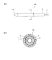
- FIG. 1 is a perspective view showing a use state of the dilatation catheter.
- 2A and 2B are views showing a state when the expansion / contraction member of the expansion catheter is expanded.
- 3A and 3B are views showing a state when the expansion / contraction member of the expansion catheter is stored.
- FIG. 4 is a diagram illustrating an example of the structure of the skeleton member.
- 5A to 5D are views for explaining a method of using the dilatation catheter.
- 6A to 6D are views for explaining a method of using the dilatation catheter.
- FIG. 7 is a diagram for explaining another example of the method for connecting the skeleton member and the shaft-shaped member.
- FIG. 1 is a perspective view showing a use state of an expansion catheter 100 according to an embodiment of the present invention.
- the expansion / contraction member 1 of the expansion catheter 100 is schematically shown.
- the far side (distal side) viewed from the user of the dilatation catheter 100 is the distal end side
- the near side (proximal side) viewed from the user is the proximal end side.
- the dilatation catheter 100 expands a cylindrical stent (intravascular indwelling device) S at an indwelling site V1 (for example, a stenosis site or an occlusion site) in the blood vessel V.
- V1 for example, a stenosis site or an occlusion site
- the stent S has a so-called self-expanding configuration in which an expanded shape is stored, and is different from the expansion catheter 100. Indwelled by a catheter. Further, for example, the stent S may be capable of being introduced into the blood vessel V while being contracted radially inward and attached to the distal end of the dilatation catheter 100 (the outer peripheral surface of the expansion / contraction member 1).
- the stent S has, for example, a structure in which metal strands are knitted in a lattice shape, and has a substantially cylindrical outer shape as a whole.
- the material of the metal strand include known metals and metal alloys represented by Ni—Ti alloy, stainless steel, titanium alloy and the like.
- the external force is applied from the inner side to the outer side in the radial direction, and the stent S is expanded in the outer side in the radial direction and is placed in close contact with the blood vessel.
- stent S was illustrated as an intravascular indwelling device, it is an example and it is not restricted to this, A stent graft (illustration omitted) etc. can be changed arbitrarily arbitrarily.
- FIG. 2A and FIG. 2B are views showing a state when the expansion / contraction member 1 of the expansion catheter 100 is expanded.
- 3A and 3B are views showing a state when the expansion / contraction member 1 of the expansion catheter 100 is stored.
- 2A and 3A are perspective views of the dilatation catheter 100.
- 2B is a cross-sectional view taken along the line AA in FIG. 2A
- FIG. 3B is a cross-sectional view taken along the line BB in FIG. 3A.
- the expansion catheter 100 is introduced into the blood vessel V with the expansion / contraction member 1 stored in the sheath tube 4 (see FIGS. 3A and 3B), and is introduced to the indwelling site of the stent S.
- the expansion / contraction member 1 is exposed from the sheath tube 4, and the expansion / contraction member 1 is in an expanded state (see FIGS. 2A and 2B).
- the expansion / contraction member 1 is configured to be able to expand / contract without blocking the blood flow of the blood vessel V, and the dilatation catheter 100 includes a recovery mechanism for recovering the expansion / contraction member 1 from the blood vessel V.
- the expansion catheter 100 includes an expansion / contraction member 1, a balloon tube 2, a recovery member 3, a sheath tube 4, a guide tube 5, and the like.
- the expansion / contraction member 1 is disposed inside the stent S, and the balloon 12 (described later in detail) expands to press the stent S from the inside to the outside in the radial direction.
- the expansion / contraction member 1 is a member that can be expanded / contracted in the radial direction, and has a substantially spherical shape in an expanded state (see FIG. 1 and the like) and a substantially cylindrical shape in a contracted state (see FIGS. 5A and 5B).
- the outer diameter of the expansion / contraction member 1 in the contracted state is substantially equal to the inner diameter of the sheath tube 4.
- the expansion / contraction member 1 is reduced in diameter by, for example, compression in the radial direction or folding, and is accommodated in the sheath tube 4.
- the expansion / contraction member 1 is attached to the tip of the balloon tube 2.
- the expansion / contraction member 1 includes a skeleton member 11 that forms a skeleton of the expansion / contraction member 1 with a wire, and a balloon 12 that can be expanded / contracted.
- the balloon 12 is attached to the skeleton member 11 so as to cover the outer peripheral surface of the skeleton member 11.
- the skeletal member 11 and the balloon 12 are accommodated in the sheath tube 4 when the expansion catheter 100 is introduced into the blood vessel V (see FIGS. 3A and 3B), and from the sheath tube 4 when the balloon 12 is expanded. Exposed (see FIGS. 2A and 2B).
- the balloon 12 is an expansion deformation member that expands and uniformly presses the stent S in the circumferential direction.
- the balloon 12 is formed of an elastic resin material such as a thermoplastic synthetic resin, and has a two-layer structure including an inner layer 121 and an outer layer 122, for example.
- the inner layer 121 is formed in close contact so as to cover the outer peripheral surface of a cylindrical portion 111 (described later) of the skeleton member 11.
- the inner layer 121 is a wire stitch that is spaced apart from the outer peripheral surface of the tubular portion 111 in an expanded state (a gap in which the skeleton wire is separated). Close contact).
- the outer layer 122 is bonded to the outer peripheral surface of the inner layer 121 at the distal end portion and the proximal end portion.
- the outer layer 122 expands in a substantially spherical shape radially outward (see FIGS. 2A and 2B).
- the substantially spherical shape was illustrated as a shape in the expansion state of the balloon 12 (outer layer 122), it is an example and is not restricted to this, It can change arbitrarily arbitrarily.
- the skeleton member 11 includes a cylindrical portion 111 that is in close contact with the balloon 12, and a connection portion 112 that is connected to the tip of the balloon tube 2 (axial member), and has a distal end portion and a proximal end portion (axial direction). Of both ends). Thereby, even if the balloon 12 is expanded, the blood can flow through the lumen formed by the skeleton member 11 and does not block the blood flow. In addition, since the balloon 12 is disposed outside the high-strength skeleton member 11, a pressing force can be efficiently applied to the stent S.
- the connecting portion 112 is connected to the balloon tube 2 by, for example, stitching using a thread. However, the connecting method is an example and is not limited thereto, and can be arbitrarily changed as appropriate.
- the skeleton member 11 is configured to be expandable and contractible, and is in an expanded state when the balloon 12 is expanded.
- the skeleton member 11 has a so-called self-expanding shape in which the shape of the expanded state is stored, and expands radially outward with exposure from the sheath tube 4.
- the skeleton member 11 can be expanded and contracted by being formed by braiding the wire.
- the distal end side (distal end side) of the cylindrical portion 111 is open (opening 111 a), and the connection portion 112 is exposed from the balloon 12. Therefore, the blood flows into the lumen of the expansion / contraction member 1 through the opening 111a or the mesh (not shown) of the connecting portion 112, and flows out to the blood vessel V through the mesh (not shown) or the opening 111a of the connecting portion 112.
- Examples of the material of the wire forming the skeleton member 11 include known metals or metal alloys represented by Ni—Ti alloy, stainless steel, titanium alloy and the like. An alloy material having X-ray contrast properties may be used. In this case, the position of the expansion / contraction member 1 can be confirmed from outside the body.
- the method of weaving the wire is not particularly limited, and for example, a method of knitting so as to alternately mesh a plurality of wires (see FIG. 4) or a method of weaving a plurality of wires in a spiral shape (not shown) can be applied.
- the weaving method may be different between the tubular portion 111 and the connecting portion 112.
- the skeleton member 11 is formed by a method in which a plurality of wire rods shown in FIG. 4 are alternately knitted, even when pulled in the axial direction, deformation (extension) in the axial direction is restricted by the adjacent wire rod.
- the amount of elongation in the axial direction is smaller than when formed by a method of braiding a plurality of wire rods in a spiral shape.
- the skeletal member 11 has a configuration that hardly extends in the axial direction, the rigidity in the radial direction is increased. Therefore, when the balloon 12 is expanded, the lumen of the skeletal member 11 is not easily crushed, and the blood flow path is surely provided. Can be held. Moreover, since the deformation in the axial direction when the expanding / contracting member 1 shifts from the contracted state to the expanded state is small, the expanding / contracting member 1 can be easily positioned at a desired indwelling site. Further, since the skeleton member 11 hardly extends in the axial direction, the entire expansion / contraction member 1 hardly expands in the axial direction. For example, the diameter of the expansion / contraction member 1 is reduced without substantially extending in the axial direction, so that the inside of the sheath tube 4 is reduced. Can be stored.
- the expansion / contraction member 1 constitutes an expandable / contractable structure that presses the inner surface of the stent (intravascular indwelling device) S outward in the radial direction.
- a guide tube 5 is disposed on the radially inner side of the balloon tube 2.
- the guide tube 5 is a guide wire (not shown) inserted through the guide tube 5 when the dilatation catheter 100 is introduced into the blood vessel.
- a tip 51 is attached to the tip of the guide tube 5.
- the tip 51 has, for example, a shape in which the outer diameter on the proximal end side is substantially equal to the inner diameter of the sheath tube 4 and the diameter decreases toward the distal end side.
- a recovery member 3 is disposed on the radially outer side of the balloon tube 2.
- the recovery member 3 is for recovering the expansion / contraction member 1 in the sheath tube 4.
- the recovery member 3 has a long tubular portion 31 inserted in the sheath tube 4, and a recovery assist for assisting the recovery of the expansion / contraction member 1 into the sheath tube 4 at the distal end thereof.
- the part 32 is continuously provided.
- the recovery assisting part 32 is configured to be expandable / contractable in the radial direction, and in the expanded state, the proximal end part (proximal end part) of the expansion / contraction member 1 from the distal end side, for example, the connection part 112 of the expansion / contraction member 1 or the outer layer of the balloon 12. 122 etc. can be inserted and can be arrange
- the collection assisting portion 32 is open at the distal end side and is expanded in diameter so as to cover the proximal end portion of the expansion / contraction member 1.
- the outer diameter of the distal end portion in a state where the collection assisting portion 32 is expanded is larger than the outer diameter of the proximal end portion in a state where the expansion / contraction member 1 is contracted.
- the recovery assisting portion 32 is formed in a tapered shape having a diameter reduced toward the proximal end side from the distal end side to the proximal end side in the expanded state.
- the recovery assisting part 32 is configured to be contractible so that the outer diameter of the recovery assisting part 32 is smaller than the inner diameter of the sheath tube 4 when accommodated in the sheath tube 4.
- the outer surface of the collection auxiliary portion 32 comes into contact with the open end 41 of the sheath tube 4, and the outer surface of the collection auxiliary portion 32 is in contact with it.
- the recovery assisting portion 32 can be contracted in the radial direction.
- a force is applied radially inward to the outer surface of the proximal end portion of the expansion / contraction member 1 disposed inside the collection assisting portion 32, so that the base of the expansion / contraction member 1 is The end can be contracted in the radial direction.
- the collection assisting portion 32 is configured to cover the proximal end portion of the expansion / contraction member 1, and contracts so that the outer diameter is smaller than the inner diameter of the sheath tube 4, thereby allowing the sheath tube 4 to shrink. It can be accommodated in.
- assistant part 32 is formed by the braiding of a wire, for example, and can be expanded and contracted.
- the collection assisting portion 32 has a so-called self-expanding shape in which the shape of the expanded state is stored, and expands radially outward toward the distal end side with exposure from the sheath tube 4. It is preferable that the space
- examples of the material of the wire forming the collection assisting part 32 include known metals or metal alloys represented by Ni—Ti alloy, stainless steel, titanium alloy and the like. An alloy material having X-ray contrast properties may be used.
- a sheath tube 4 is disposed on the radially outer side of the recovery member 3. That is, the sheath tube 4, the tubular portion 31 of the collection member 3, the balloon tube 2, and the guide tube 5 are arranged in a nested manner in order from the radially outer side. Further, the sheath tube 4, the recovery member 3 (tubular portion 31), the balloon tube 2 and the guide tube 5 can be moved in the axial direction independently of each other.
- Each of the sheath tube 4, the tubular portion 31 of the recovery member 3, the balloon tube 2 and the guide tube 5 is a long tubular member formed of, for example, a flexible material.
- flexible materials include synthetic resins (elastomers), resin compounds in which other materials are mixed with synthetic resins, multilayer structures in which synthetic resins are composed of multiple layers, or synthetic resins and metal wires. A composite etc. are mentioned.
- the catheter 100 for expansion may have the operation part operated by the user on the base end side.
- a fluid injection tube (not shown) for injecting an expansion solution (for example, physiological saline) L or gas into the balloon 12 is inserted into the sheath tube 4, the recovery member 3, or the balloon tube 2.
- the tip of the fluid injection tube is inserted into the balloon 12 (between the inner layer 121 and the outer layer 122).
- a method of using the expansion catheter 100 will be described with reference to FIGS. 5A to 5D and FIGS. 6A to 6D.
- a stent S with an insufficient expansion amount is placed in a predetermined position V1 (for example, a stenosis site) in the blood vessel V.
- a guide wire (not shown) is inserted into the blood vessel V in advance, and the dilatation catheter 100 is introduced along the guide wire.
- FIGS. 5A to 5D are views for explaining a method of using the expansion catheter 100, and schematically show a state in which the stent 1 is expanded.
- the dilatation catheter 100 is inserted into the blood vessel V along a guide wire (not shown) inserted into the blood vessel V, and the expansion / contraction member 1 is positioned inside the stent S.
- the sheath tube 4 is moved to the proximal side (hand side) along the axial direction in a state where the position of the expansion / contraction member 1 is fixed.
- the expansion / contraction member 1 is discharged into the blood vessel V from the
- the portion of the expansion / contraction member 1 exposed from the sheath tube 4 is expanded by the self-expanding force of the skeleton member 11.
- the balloon 12 is also elastically deformed following the expansion of the skeleton member 11.
- the expandable member 1 is released from the sheath tube 4 by moving the expandable member 1 along the axial direction so as to be pushed to the distal side (tip side). Also good.
- the expansion / contraction member 1 As the expansion / contraction member 1 further expands, the inner surface of the blood vessel V is pressed radially outward by the stent S, and the stenosis site V1 expands (see FIG. 5D). Even in this state, blood flow in the blood vessel V is ensured.
- FIGS. 6A to 6D are views for explaining a method of using the dilatation catheter 100, and schematically show a state in which the expansion / contraction member 1 is recovered in the sheath tube 4.
- FIG. 6A to 6D are views for explaining a method of using the dilatation catheter 100, and schematically show a state in which the expansion / contraction member 1 is recovered in the sheath tube 4.
- the expansion solution L in the balloon 12 is discharged, the balloon 12 is deflated, and the recovery member 3 is sheathed so that the recovery auxiliary portion 32 is disposed on the proximal end side of the expansion / contraction member 1.
- the portion of the recovery assisting part 32 exposed from the sheath tube 4 is expanded by the self-expanding force of the recovery assisting part 32.
- the outer diameter of the distal end side is larger than the outer diameter of the contracted expansion / contraction member 1.
- the balloon tube 2 is moved to the proximal side (hand side) along the axial direction.
- the proximal end portion of the expansion / contraction member 1 for example, the connection portion 112 of the expansion / contraction member 1, the outer layer 122 of the balloon 12, etc.
- the collection member 3 and the balloon tube 2 are moved to the proximal side (hand side) along the axial direction with respect to the sheath tube 4, thereby opening the opening end portion of the sheath tube 4.
- the expansion catheter 100 is pulled out from the blood vessel V while the stent S is indwelling.
- the expansion catheter 100 is an expansion catheter 100 that expands the cylindrical stent S (intravascular indwelling device) placed in a predetermined position in the blood vessel V, and is a sheath tube. 4, an expandable / contractible member 1 (structure) that presses the inner surface of the stent S radially outward, and a recovery member 3 for recovering the expandable member 1 in the sheath tube 4.
- the member 3 has a recovery assisting portion 32 that assists the recovery of the expansion / contraction member 1 into the sheath tube 4, and the recovery assisting portion 32 covers the base end portion of the expansion / contraction member 1 and can be accommodated in the sheath tube 4. It is configured.
- the base end portion of the expansion / contraction member 1 is covered by the recovery assisting portion 32 of the recovery member 3 so that the base end portion of the expansion / contraction member 1 is covered. Can be prevented from being caught on the open end 41 of the sheath tube 4.
- the expansion / contraction member 1 is configured to include the skeleton member 1, the balloon 12, and the like so that the blood flow is not blocked in the state where the expansion / contraction member 1 is placed in the blood vessel V, the proximal ends of the skeleton member 1, the balloon 12, and the like
- the portion By covering the portion with the recovery assisting portion 32, the portion can be accommodated in the sheath tube 4 without being caught by the opening end portion 41 of the sheath tube 4.
- the expansion / contraction member 1 can be properly accommodated in the sheath tube 4.
- the recovery member 3 further includes a tubular portion 31 that is provided with a collection auxiliary portion 32 at the distal end and is inserted into the sheath tube 4.
- the collection auxiliary portion 32 is orthogonal to the axial direction of the tubular portion 31. It can be expanded and contracted in the radial direction, and can be disposed inside by inserting the proximal end portion of the expansion / contraction member 1 from the distal end side in the expanded state.
- the outer diameter of the portion 32 is configured to be shrinkable so as to be smaller than the inner diameter of the sheath tube 4.
- the expandable / retractable collection assisting portion 32 can cover the proximal end portion of the expanding / contracting member 1 in the expanded state so that the proximal end portion of the expanding / contracting member 1 is not easily caught on the open end portion 41 of the sheath tube 4. It can be properly accommodated in the sheath tube 4 in the contracted state. In particular, when the collection auxiliary portion 32 is accommodated in the sheath tube 4, the outer surface of the collection auxiliary portion 32 comes into contact with the open end 41 of the sheath tube 4 and is radially inward with respect to the outer surface of the collection auxiliary portion 32. When the force is applied to the recovery assisting portion 32, the recovery assisting portion 32 can be contracted.
- the base end portion of the expansion / contraction member 1 disposed inside the recovery auxiliary portion 32 can be contracted in the radial direction in accordance with the contraction of the recovery auxiliary portion 32, and the expansion / contraction member 1 into the sheath tube 4 can be contracted. Can be easily accommodated. Thereby, the collection
- the configuration of the collection assisting portion 32 exemplified in the above embodiment is an example and is not limited to this, and although not illustrated, the interval between the wire members constituting the collection assisting portion 32 is set to the skeleton member 11. It may be larger than the interval between the wires, or may be configured to include a film body so as to close the gap between the wires.
- the expansion / contraction member 1 expands to a substantially spherical shape
- this is an example and the present invention is not limited to this, and the shape of the expansion / contraction member 1 at the time of expansion can be arbitrarily changed as appropriate. That is, any shape that can uniformly press the intravascular indwelling device such as the stent S radially outward in a state where the expansion / contraction member 1 is expanded and deformed may be used.
- the outer layer 122 may be easily extended relative to the inner layer 121.
- the inner layer 121 and the outer layer 122 are easily extended relative to the inner layer 121 by making at least one of the thickness and the material different, for example. That is, the inner layer 121 is made thicker than the outer layer 122 using the same resin material, or the inner layer 121 and the outer layer 122 have the same thickness, and the inner layer 121 is harder than the outer layer 122.
- the outer layer 122 is formed with respect to the inner layer 121 by forming or forming the inner layer 121 to be thicker than the outer layer 122 and using a resin material in which the inner layer 121 is harder than the outer layer 122. Relatively easy to extend.
- the inner layer 121 of the balloon 12 is hardly expanded and deformed, and the outer layer 122 is easily expanded and deformed outward in the radial direction.
- the stent S can be appropriately expanded by expanding the balloon 12 while suppressing the blockage of the stent S.
- the outer layer 122 of the balloon 12 be easily expanded and deformed while having a predetermined strength. That is, the outer layer 122 has, for example, a predetermined thickness and hardness, so that it can be hardly broken even if it contacts the inside of the collection assisting portion 32 when the expansion / contraction member 1 is recovered. It can be done more appropriately.
- the outer layer 122 may be composed of two or more layers.
- the inner side may be a layer that is easily expanded and deformed, and the outer side may be a layer having a predetermined strength.
- connection portion 112 provided on the proximal end side of the cylindrical portion 111 is connected to the balloon tube 2 (axial member) is described, but other structures may be applied. it can.
- the distal end side connection portion 112A and the proximal end side connection portion 112B are provided on the distal end side and the proximal end side of the cylindrical portion 111, respectively.
- the distal end side connection portion 112A and the proximal end side connection portion 112B may be connected to the holding tube 52 (axial member) and the balloon tube 2 (axial member), respectively.
- the distal end side connection portion 112 ⁇ / b> A has a configuration in which a plurality of wires 11 a extending from the distal end portion of the cylindrical portion 111 toward the distal end side are converged to the center and connected to the holding tube 52.
- the holding tube 52 is inserted into the guide tube 5 and held so as to be movable in the axial direction.
- the wires 11 a of the distal end side connection portion 112 ⁇ / b> A are arranged at intervals in the circumferential direction of the holding tube 52, and are connected to the holding tube 52 so as to form a radial shape.
- the base end side connection part 112 ⁇ / b> B has a configuration in which a plurality of wires 11 b extending from the base end part of the tubular part 111 toward the base end side are converged to the center and connected to the balloon tube 2.
- Each wire 11b of the base end side connection part 112B is arranged at intervals in the circumferential direction of the balloon tube 2 and is connected to the balloon tube 2 so as to form a radial shape.
- the distal end side of the inner layer 121 reaches a position that covers a part of the wire 11a of the distal end side connection portion 112A
- the proximal end side of the inner layer 121 reaches a position that covers a part of the wire 11b of the proximal end side connection portion 112B.
- the overall shape of the inner layer 121 has a cylindrical shape in which both ends on the distal end side and the proximal end side are slightly recessed.
- the skeleton member 11 is stably held substantially coaxially with respect to the balloon tube 2 and the guide tube 5 by providing the distal end side connection portion 112A and the proximal end side connection portion 112B at both ends of the cylindrical portion 111.
- the radial rigidity of the skeleton member 11 can be further increased, and the lumen of the skeleton member 11 is not easily crushed when the balloon 12 is expanded, so that the blood flow path can be reliably retained.
- the shaft-shaped member may not be a tube (tube) shape but may be a wire (line) shape.
- the distal end side connecting portion 112A and the proximal end side connecting portion 112B may be connected to the same shaft-like member.
- the skeleton member 11 may be formed by, for example, laser processing (laser cutting) a single metal pipe (for example, a pipe made of a Ni—Ti alloy).
- the stent expansion device having a configuration in which the stent S or the stent graft in a radially contracted state is attached to the distal end side of the expansion catheter 100, the stent S or the stent graft can be moved to a predetermined position in the blood vessel V. Indwelling can be performed more easily.
- any structure may be used as long as it is a recovery mechanism for recovering the expandable member 1 from within the blood vessel V.
- the sheath tube 4 and the sheath tube 4 have an internal structure.
- a recovery member 3 for recovering the expansion / contraction member 1, and the recovery member 3 has a recovery auxiliary portion 32 for assisting recovery of the expansion / contraction member 1 into the sheath tube 4. Should just be comprised so that the base end part of the expansion / contraction member 1 may be accommodated in the sheath tube 4.
Abstract
拡縮可能な構造体のシース内への収容を適正に行う。 拡縮可能な拡縮部材1を血管V内から回収する回収機構である。シースチューブ4と、シースチューブ内に拡縮部材を回収するための回収用部材3と、を備える。回収用部材は、シースチューブ内への拡縮部材の回収を補助する回収補助部32を有し、回収補助部は、拡縮部材の基端部を覆ってシースチューブに収容可能に構成されている。
Description
本発明は、回収機構及び拡張用カテーテルに関する。
従来、血管内の所定位置に留置されるステントやステントグラフト等の血管内留置具を、バルーンを用いて拡張させるバルーンカテーテルが知られている(例えば、特許文献1参照)。
しかしながら、特許文献1等の場合、拡張したバルーンにより血管が閉塞されて血流が遮断されてしまう。そこで、血管内留置具を拡張させる拡縮部材の骨格に線材を用いて血流を確保する構成が考えられるが、この場合、拡縮部材(線材構造体)をシース内に収容する際にシースの開口端に線材やバルーンが引っ掛かり易くなって、当該拡縮部材の収容を適正に行うことができない虞がある。
上記した課題は、血流を遮断しつつ血管内留置具を拡張する構成であっても、例えば、バルーンやシースなどの形態(例えば、寸法、形状、材質等)によっては生じ得る。
上記した課題は、血流を遮断しつつ血管内留置具を拡張する構成であっても、例えば、バルーンやシースなどの形態(例えば、寸法、形状、材質等)によっては生じ得る。
本発明の目的は、拡縮可能な構造体のシース内への収容を適正に行うことができる回収機構及び拡張用カテーテルを提供することである。
本発明の回収機構は、
拡縮可能な構造体を血管内から回収する回収機構であって、
シースと、
前記シース内に前記構造体を回収するための回収用部材と、を備え、
前記回収用部材は、
前記シース内への前記構造体の回収を補助する回収補助部を有し、
前記回収補助部は、前記構造体の基端部を覆って前記シースに収容可能に構成されていることを特徴としている。
拡縮可能な構造体を血管内から回収する回収機構であって、
シースと、
前記シース内に前記構造体を回収するための回収用部材と、を備え、
前記回収用部材は、
前記シース内への前記構造体の回収を補助する回収補助部を有し、
前記回収補助部は、前記構造体の基端部を覆って前記シースに収容可能に構成されていることを特徴としている。
また、本発明の拡張用カテーテルは、
血管内の所定位置に留置される筒状の血管内留置具を拡張させる拡張用カテーテルであって、
シースと、
前記血管内留置具の内側面を径方向外側に押圧する拡縮可能な構造体と、
前記シース内に前記構造体を回収するための回収用部材と、を備え、
前記回収用部材は、
前記シース内への前記構造体の回収を補助する回収補助部を有し、
前記回収補助部は、前記構造体の基端部を覆って前記シースに収容可能に構成されていることを特徴としている。
血管内の所定位置に留置される筒状の血管内留置具を拡張させる拡張用カテーテルであって、
シースと、
前記血管内留置具の内側面を径方向外側に押圧する拡縮可能な構造体と、
前記シース内に前記構造体を回収するための回収用部材と、を備え、
前記回収用部材は、
前記シース内への前記構造体の回収を補助する回収補助部を有し、
前記回収補助部は、前記構造体の基端部を覆って前記シースに収容可能に構成されていることを特徴としている。
本発明によれば、拡縮可能な構造体のシース内への収容を適正に行うことができる。
以下、本発明の実施形態を、図面を参照して詳細に説明する。
図1は、本発明の一実施形態に係る拡張用カテーテル100の使用状態を示す斜視図である。
図1では、拡張用カテーテル100の拡縮部材1を模式的に表している。後述する図2A及び図2B、図5A~図5D並びに図6A~図6Dにおいても同様である。以下の説明では、拡張用カテーテル100の使用者からみて遠い方(遠位側)を先端側、使用者からみて近い方(近位側)を基端側とする。
図1では、拡張用カテーテル100の拡縮部材1を模式的に表している。後述する図2A及び図2B、図5A~図5D並びに図6A~図6Dにおいても同様である。以下の説明では、拡張用カテーテル100の使用者からみて遠い方(遠位側)を先端側、使用者からみて近い方(近位側)を基端側とする。
図1に示すように、拡張用カテーテル100は、血管V内の留置部位V1(例えば、狭窄部位や閉塞部位等)にて筒状のステント(血管内留置具)Sを拡張させるものである。
ステントSには公知のものを適用でき、ここでは詳細な説明は省略するが、例えば、拡張状態の形状が記憶された、いわゆる自己拡張型の構成を有し、拡張用カテーテル100とは別のカテーテルによって留置される。また例えば、ステントSは、径方向内側に収縮されて拡張用カテーテル100の先端(拡縮部材1の外周面)に装着された状態で血管V内に導入可能なものであってもよい。
また、ステントSは、例えば、金属素線が格子状に編み込まれた構造を有し、全体として略円筒状の外形を有する。金属素線の材料としては、例えば、Ni-Ti合金、ステンレス鋼、チタン合金などに代表される公知の金属や金属合金が挙げられる。ステントSは、例えば、内側から径方向外側に外力が加えられることで、径方向外側に拡張し、血管に密着した状態で留置される。
なお、血管内留置具として、ステントSを例示したが、一例であってこれに限られるものではなく、ステントグラフト(図示略)など適宜任意に変更可能である。
図2A及び図2Bは、拡張用カテーテル100の拡縮部材1の拡張時の状態を示す図である。図3A及び図3Bは、拡張用カテーテル100の拡縮部材1の収納時の状態を示す図である。このうち、図2A及び図3Aは、拡張用カテーテル100の斜視図である。また、図2Bは、図2AのA-A断面図であり、図3Bは、図3AのB-B断面図である。
拡張用カテーテル100は、拡縮部材1がシースチューブ4に収納された拡縮部材1の収納状態(図3A及び図3B参照)で血管V内に導入され、ステントSの留置部位まで導入された後、拡縮部材1がシースチューブ4から露出し、拡縮部材1の拡張状態(図2A及び図2B参照)となる。また、拡縮部材1は、血管Vの血流を遮断せずに拡縮可能に構成され、拡張用カテーテル100は、拡縮部材1を血管V内から回収する回収機構を備えている。
図2A及び図2B並びに図3A及び図3Bに示すように、拡張用カテーテル100は、拡縮部材1、バルーンチューブ2、回収用部材3、シースチューブ4及びガイドチューブ5等を備える。
拡縮部材1は、ステントSの内側に配置され、バルーン12(詳細後述)が拡張することによりステントSを内側から径方向外側に押圧する。拡縮部材1は、径方向に拡縮可能な部材であり、拡張状態において略球形状をなすとともに(図1等参照)、収縮状態において略筒形状をなす(図5A及び図5B参照)。収縮状態における拡縮部材1の外径は、シースチューブ4の内径とほぼ同等である。拡縮部材1は、例えば、径方向への圧縮、又は折り畳みにより縮径され、シースチューブ4に収納される。拡縮部材1は、バルーンチューブ2の先端に取り付けられている。
具体的には、拡縮部材1は、線材により当該拡縮部材1の骨格を構成する骨格部材11と、拡縮変形可能なバルーン12とを有する。
バルーン12は、骨格部材11の外周面を覆うように骨格部材11に貼着されている。骨格部材11及びバルーン12は、拡張用カテーテル100を血管V内に導入するときには、シースチューブ4内に収納されており(図3A及び図3B参照)、バルーン12を拡張するときにシースチューブ4から露出する(図2A及び図2B参照)。
バルーン12は、骨格部材11の外周面を覆うように骨格部材11に貼着されている。骨格部材11及びバルーン12は、拡張用カテーテル100を血管V内に導入するときには、シースチューブ4内に収納されており(図3A及び図3B参照)、バルーン12を拡張するときにシースチューブ4から露出する(図2A及び図2B参照)。
バルーン12は、拡張してステントSを周方向に均一に押圧する拡張変形部材である。また、バルーン12は、例えば、熱可塑性合成樹脂などの弾性を有する樹脂材料で形成され、例えば、内層121及び外層122からなる二層構造を有する。
内層121は、骨格部材11の筒状部111(後述)の外周面を覆うように密着して形成される。具体的には、例えば、線材の編込みにより筒状部111が形成される場合、内層121は、筒状部111の外周面に拡張状態にて離間する線材の編目(骨格線材が離間した隙間部分)を閉塞するように密着されている。
外層122は、先端部と基端部において、内層121の外周面に接着される。内層121と外層122の間に拡張溶液Lが注入されることにより、外層122が径方向外側に略球形状に拡張する(図2A及び図2B参照)。
なお、バルーン12(外層122)の拡張状態での形状として、略球形状を例示したが、一例であってこれに限られるものではなく、適宜任意に変更可能である。
骨格部材11は、バルーン12と密着する筒状部111と、バルーンチューブ2(軸状部材)の先端に接続される接続部112とを有し、遠位端部と近位端部(軸方向の両端部)が連通している。これにより、バルーン12が拡張しても、血液は骨格部材11によって形成される内腔を流れることができ、血流を遮断することがない。また、強度の高い骨格部材11の外側にバルーン12が配置されているので、ステントSに対して効率よく押圧力を付与することができる。
接続部112は、例えば、糸を用いた縫合により、バルーンチューブ2に接続されるが、接続方法は一例であってこれに限られるものではなく、適宜任意に変更可能である。
接続部112は、例えば、糸を用いた縫合により、バルーンチューブ2に接続されるが、接続方法は一例であってこれに限られるものではなく、適宜任意に変更可能である。
また、骨格部材11は、拡縮自在に構成され、バルーン12が拡張する際に、拡張状態となることが好ましい。具体的には、骨格部材11は、拡張状態の形状が記憶された、いわゆる自己拡張性を有するものであり、シースチューブ4からの露出に伴い、径方向外側に拡張する。これにより、ステントSを血管Vに押し付ける際のバルーン12の拡張量をより小さくすることができ、バルーン12に注入する拡張溶液Lの量が少なくなって、ステントSに対して所望の押圧力を容易に付与することができる。
なお、骨格部材11の筒状部111の先端部をガイドチューブ5やチップ51(後述)に接続し、ガイドチューブ5を軸方向に移動させることで骨格部材11の拡張量を調整可能な構成としてもよい。
なお、骨格部材11の筒状部111の先端部をガイドチューブ5やチップ51(後述)に接続し、ガイドチューブ5を軸方向に移動させることで骨格部材11の拡張量を調整可能な構成としてもよい。
また、骨格部材11は、線材の編み込みにより形成されることで、拡縮自在となっている。また、骨格部材11において、筒状部111の先端側(遠位端側)は開放されており(開口111a)、接続部112はバルーン12から露出している。したがって、血液は、開口111a又は接続部112の網目(符号略)を介して拡縮部材1の内腔に流れ込み、接続部112の網目(符号略)又は開口111aを介して血管Vに流れ出す。
骨格部材11を形成する線材の材料としては、例えば、Ni-Ti合金、ステンレス鋼、チタン合金などに代表される公知の金属又は金属合金等が挙げられる。また、X線造影性を有する合金材料を用いてもよい。この場合、拡縮部材1の位置を体外から確認することができるようになる。
線材の編み込み方法は、特に制限されないが、例えば、複数の線材を交互にかみ合わせるように編み込む方法(図4参照)、又は複数の線材を螺旋状に編み込む方法(図示略)を適用できる。なお、筒状部111と接続部112とで編み込み方法が異なっていてもよい。
ここで、骨格部材11において、少なくとも筒状部111は、軸方向にほとんど伸張しない構成を有することが好ましい。例えば、骨格部材11が、図4に示す複数の線材を交互にかみ合わせるように編み込む方法で形成される場合、軸方向に引っ張っても、隣接する線材によって軸方向への変形(伸張)が規制され、複数の線材を螺旋状に編み込む方法で形成される場合に比較して、軸方向への伸長量は小さくなる。
ここで、骨格部材11において、少なくとも筒状部111は、軸方向にほとんど伸張しない構成を有することが好ましい。例えば、骨格部材11が、図4に示す複数の線材を交互にかみ合わせるように編み込む方法で形成される場合、軸方向に引っ張っても、隣接する線材によって軸方向への変形(伸張)が規制され、複数の線材を螺旋状に編み込む方法で形成される場合に比較して、軸方向への伸長量は小さくなる。
また、骨格部材11が軸方向にほとんど伸張しない構成を有することにより、径方向の剛性が高くなるので、バルーン12の拡張時に骨格部材11の内腔が潰れにくくなり、血液の流路を確実に保持することができる。また、拡縮部材1が収縮状態から拡張状態に移行するときの軸方向の変形が小さいので、拡縮部材1を所望の留置部位に容易に位置させることができる。
さらに、骨格部材11が軸方向にほとんど伸長しないことにより拡縮部材1全体が軸方向にほとんど伸張しなくなり、例えば、当該拡縮部材1を軸方向にほとんど伸長させることなく縮径してシースチューブ4内に収納することができる。
さらに、骨格部材11が軸方向にほとんど伸長しないことにより拡縮部材1全体が軸方向にほとんど伸張しなくなり、例えば、当該拡縮部材1を軸方向にほとんど伸長させることなく縮径してシースチューブ4内に収納することができる。
このように、拡縮部材1は、ステント(血管内留置具)Sの内側面を径方向外側に押圧する拡縮可能な構造体を構成している。
バルーンチューブ2の径方向内側には、ガイドチューブ5が配置されている。
ガイドチューブ5は、拡張用カテーテル100を血管内に導入する際、ガイドチューブ5にガイドワイヤー(図示略)が挿通されるものである。また、ガイドチューブ5の先端に、チップ51が取り付けられている。
チップ51は、例えば、基端側の外径がシースチューブ4の内径と略等しく、先端側に向かって縮径する形状を有する。
ガイドチューブ5は、拡張用カテーテル100を血管内に導入する際、ガイドチューブ5にガイドワイヤー(図示略)が挿通されるものである。また、ガイドチューブ5の先端に、チップ51が取り付けられている。
チップ51は、例えば、基端側の外径がシースチューブ4の内径と略等しく、先端側に向かって縮径する形状を有する。
バルーンチューブ2の径方向外側には、回収用部材3が配置されている。
回収用部材3は、シースチューブ4内に拡縮部材1を回収するためのものである。具体的には、回収用部材3は、シースチューブ4に内挿された長尺な管状部31を有し、その先端部に、シースチューブ4内への拡縮部材1の回収を補助する回収補助部32が連設されている。
回収用部材3は、シースチューブ4内に拡縮部材1を回収するためのものである。具体的には、回収用部材3は、シースチューブ4に内挿された長尺な管状部31を有し、その先端部に、シースチューブ4内への拡縮部材1の回収を補助する回収補助部32が連設されている。
回収補助部32は、径方向に拡縮可能に構成され、拡張状態にて先端側から拡縮部材1の基端部(近位端部)、例えば、拡縮部材1の接続部112やバルーン12の外層122等を挿入して内側に配設可能となっている。具体的には、回収補助部32は、先端側が開放されているとともに、拡縮部材1の基端部を覆うことができるように拡径している。すなわち、回収補助部32が拡径した状態での先端部の外径は、拡縮部材1が収縮した状態での基端部の外径よりも大きくなっている。また、回収補助部32は、拡張状態にて先端側から基端側にかけて基端側ほど縮径されたテーパ状に形成されている。
また、回収補助部32は、シースチューブ4内に収容される際に、当該回収補助部32の外径がシースチューブ4の内径よりも小さい寸法となるように収縮可能に構成されている。具体的には、シースチューブ4内に回収補助部32が収容される際に、シースチューブ4の開口端部41に回収補助部32の外面が接触して当該回収補助部32の外面に対して径方向内側に力が加えられることで、回収補助部32を径方向に収縮可能となっている。そして、回収補助部32の収縮に応じて、当該回収補助部32の内側に配設された拡縮部材1の基端部の外面に対して径方向内側に力が加えられ、拡縮部材1の基端部を径方向に収縮可能となっている。
このように、回収補助部32は、拡縮部材1の基端部を覆うことができるように構成され、外径がシースチューブ4の内径よりも小さい寸法となるように収縮することでシースチューブ4に収容可能に構成されている。
また、回収補助部32は、例えば、線材の編み込みにより形成され、拡縮自在となっている。具体的には、回収補助部32は、拡張状態の形状が記憶された、いわゆる自己拡張性を有するものであり、シースチューブ4からの露出に伴い、先端側ほど径方向外側に拡張する。
回収補助部32を構成する線材どうしの間隔は、例えば、骨格部材11の接続部112が引っ掛かり難くなるように、当該骨格部材11の線材どうしの間隔よりも小さくなっているのが好ましい。
回収補助部32を構成する線材どうしの間隔は、例えば、骨格部材11の接続部112が引っ掛かり難くなるように、当該骨格部材11の線材どうしの間隔よりも小さくなっているのが好ましい。
なお、回収補助部32を形成する線材の材料としては、例えば、Ni-Ti合金、ステンレス鋼、チタン合金などに代表される公知の金属又は金属合金等が挙げられる。また、X線造影性を有する合金材料を用いてもよい。
回収用部材3の径方向外側には、シースチューブ4が配置されている。
すなわち、シースチューブ4、回収用部材3の管状部31、バルーンチューブ2、ガイドチューブ5は、径方向外側から順に入れ子状に配置されている。また、シースチューブ4、回収用部材3(管状部31)、バルーンチューブ2及びガイドチューブ5は、相互に独立して軸方向に移動できるようになっている。
すなわち、シースチューブ4、回収用部材3の管状部31、バルーンチューブ2、ガイドチューブ5は、径方向外側から順に入れ子状に配置されている。また、シースチューブ4、回収用部材3(管状部31)、バルーンチューブ2及びガイドチューブ5は、相互に独立して軸方向に移動できるようになっている。
なお、シースチューブ4、回収用部材3の管状部31、バルーンチューブ2及びガイドチューブ5の各々は、例えば、可撓性を有する材料で形成された長尺の管状部材である。可撓性を有する材料としては、例えば、合成樹脂(エラストマー)、合成樹脂に他の材料が混合された樹脂コンパウンド、合成樹脂が多層で構成された多層構造体、または合成樹脂と金属線との複合体等が挙げられる。
なお、図示は省略するが、拡張用カテーテル100は、基端側に、使用者により操作される操作部を有していてもよい。また、シースチューブ4、回収用部材3又はバルーンチューブ2には、バルーン12に拡張溶液(例えば、生理食塩水)L又は気体を注入するための流体注入チューブ(図示略)が内挿される。流体注入チューブの先端は、バルーン12の内部(内層121と外層122の間)に挿入される。
次に、拡張用カテーテル100の使用方法について、図5A~図5D並びに図6A~図6Dを参照して説明する。
なお、以下の説明では、血管V内の所定位置V1(例えば、狭窄部位)に拡張量が十分でないステントSが留置されているものとする。また、事前に血管V内にガイドワイヤ(図示略)が挿通されており、このガイドワイヤに沿って拡張用カテーテル100が導入されるものとする。
なお、以下の説明では、血管V内の所定位置V1(例えば、狭窄部位)に拡張量が十分でないステントSが留置されているものとする。また、事前に血管V内にガイドワイヤ(図示略)が挿通されており、このガイドワイヤに沿って拡張用カテーテル100が導入されるものとする。
先ず、拡張用カテーテル100を用いてステントSを拡張させる際の使用方法について、図5A~図5Dを参照して説明する。
図5A~図5Dは、拡張用カテーテル100の使用方法を説明するために示す図であり、ステント1が拡張していく状態を模式的に表している。
図5A~図5Dは、拡張用カテーテル100の使用方法を説明するために示す図であり、ステント1が拡張していく状態を模式的に表している。
図5Aに示すように、先ず、血管V内に挿通されたガイドワイヤ(図示略)に沿って拡張用カテーテル100を血管V内に挿入し、拡縮部材1をステントSの内側に位置させる。
次に、図5B及び図5Cに示すように、拡縮部材1の位置を固定した状態で、シースチューブ4を軸方向に沿って近位側(手元側)に移動させることで、当該シースチューブ4から血管V内に拡縮部材1を放出する。拡縮部材1のシースチューブ4から露出した部分は、骨格部材11の自己拡張力によって拡張する。このとき、骨格部材11の拡張に追従してバルーン12も弾性変形する。
なお、シースチューブ4の位置を固定した状態で、拡縮部材1を軸方向に沿って遠位側(先端側)に押出すように移動させることで、拡縮部材1をシースチューブ4から放出してもよい。
なお、シースチューブ4の位置を固定した状態で、拡縮部材1を軸方向に沿って遠位側(先端側)に押出すように移動させることで、拡縮部材1をシースチューブ4から放出してもよい。
この状態で、バルーン12に拡張溶液Lを注入すると、バルーン12の外層122が径方向外側に膨張し、ステントSの内周面に接触した状態となる。この状態では、拡縮部材1の先端部(骨格部材11の筒状部111の開口111a)と基端部(骨格部材11の接続部112の網目(符号略))が連通しているため、拡縮部材1により血管Vの血流は確保される。
拡縮部材1がさらに拡張していくと、ステントSにより血管Vの内面部が径方向外側に押圧されていき、狭窄部位V1が拡張していく(図5D参照)。この状態でも、血管Vの血流は確保される。
次に、拡縮部材1をシースチューブ4内に回収する際の使用方法について、図6A~図6Dを参照して説明する。
図6A~図6Dは、拡張用カテーテル100の使用方法を説明するために示す図であり、拡縮部材1をシースチューブ4内に回収していく状態を模式的に表している。
図6A~図6Dは、拡張用カテーテル100の使用方法を説明するために示す図であり、拡縮部材1をシースチューブ4内に回収していく状態を模式的に表している。
図6Aに示すように、先ず、バルーン12内の拡張溶液Lを排出してバルーン12を収縮させ、拡縮部材1の基端側に回収補助部32が配置されるように回収用部材3をシースチューブ4から露出させる。回収補助部32のシースチューブ4から露出した部分は、回収補助部32の自己拡張力によって拡張する。回収補助部32の拡張状態では、その先端側の外径は、収縮した拡縮部材1の外径よりも大きくなる。
次に、図6Bに示すように、例えば、シースチューブ4及び回収用部材3の位置を固定した状態で、バルーンチューブ2を軸方向に沿って近位側(手元側)に移動させる。これにより、回収補助部32の内側に、その先端側から拡縮部材1の基端部(例えば、拡縮部材1の接続部112やバルーン12の外層122等)が挿入されて配設される。
続けて、図6Cに示すように、シースチューブ4に対して回収用部材3及びバルーンチューブ2を軸方向に沿って近位側(手元側)に移動させることで、シースチューブ4の開口端部41に回収補助部32の外面が接触し、当該回収補助部32の外面に対して径方向内側に力が加えられる。そして、回収補助部32が径方向に収縮していくことで、当該回収補助部32の内側に配設された拡縮部材1の基端部も同様に径方向に収縮していき、拡縮部材1がシースチューブ4内に回収されていく。
シースチューブ4内に拡縮部材1全体が回収されると(図6D参照)、ステントSを留置したまま拡張用カテーテル100が血管V内から引き抜かれる。
続けて、図6Cに示すように、シースチューブ4に対して回収用部材3及びバルーンチューブ2を軸方向に沿って近位側(手元側)に移動させることで、シースチューブ4の開口端部41に回収補助部32の外面が接触し、当該回収補助部32の外面に対して径方向内側に力が加えられる。そして、回収補助部32が径方向に収縮していくことで、当該回収補助部32の内側に配設された拡縮部材1の基端部も同様に径方向に収縮していき、拡縮部材1がシースチューブ4内に回収されていく。
シースチューブ4内に拡縮部材1全体が回収されると(図6D参照)、ステントSを留置したまま拡張用カテーテル100が血管V内から引き抜かれる。
以上のように、本実施形態に係る拡張用カテーテル100は、血管V内の所定位置に留置される筒状のステントS(血管内留置具)を拡張させる拡張用カテーテル100であって、シースチューブ4と、ステントSの内側面を径方向外側に押圧する拡縮可能な拡縮部材1(構造体)と、シースチューブ4内に拡縮部材1を回収するための回収用部材3と、を備え、回収用部材3は、シースチューブ4内への拡縮部材1の回収を補助する回収補助部32を有し、回収補助部32は、拡縮部材1の基端部を覆ってシースチューブ4に収容可能に構成されている。
したがって、シースチューブ4内に拡縮部材1を回収する際に、回収用部材3の回収補助部32により拡縮部材1の基端部を覆った状態とすることで、当該拡縮部材1の基端部をシースチューブ4の開口端部41に引っ掛かり難くすることができる。例えば、拡縮部材1が、血管V内に留置された状態で血流を遮断しないように、骨格部材1やバルーン12等を有する構成であっても、当該骨格部材1やバルーン12等の基端部が回収補助部32により覆われることで、シースチューブ4の開口端部41に引っ掛かることなくシースチューブ4内に収容することができる。
このように、シースチューブ4内への拡縮部材1の収容を適正に行うことができる。
したがって、シースチューブ4内に拡縮部材1を回収する際に、回収用部材3の回収補助部32により拡縮部材1の基端部を覆った状態とすることで、当該拡縮部材1の基端部をシースチューブ4の開口端部41に引っ掛かり難くすることができる。例えば、拡縮部材1が、血管V内に留置された状態で血流を遮断しないように、骨格部材1やバルーン12等を有する構成であっても、当該骨格部材1やバルーン12等の基端部が回収補助部32により覆われることで、シースチューブ4の開口端部41に引っ掛かることなくシースチューブ4内に収容することができる。
このように、シースチューブ4内への拡縮部材1の収容を適正に行うことができる。
また、回収用部材3は、先端部に回収補助部32が連設され、シースチューブ4に内挿された管状部31をさらに有し、回収補助部32は、管状部31の軸方向に直交する径方向に拡縮可能に構成され、拡張状態にて先端側から拡縮部材1の基端部を挿入して内側に配設可能であり、シースチューブ4内に収容される際に、当該回収補助部32の外径がシースチューブ4の内径よりも小さい寸法となるように収縮可能に構成されている。
したがって、拡縮可能な回収補助部32により、拡張状態にて拡縮部材1の基端部を覆って当該拡縮部材1の基端部をシースチューブ4の開口端部41に引っ掛かり難くすることができ、収縮状態にてシースチューブ4内に適正に収容することができる。
特に、シースチューブ4内に回収補助部32が収容される際に、シースチューブ4の開口端部41に回収補助部32の外面が接触して当該回収補助部32の外面に対して径方向内側に力が加えられることで、回収補助部32を収縮することができる。さらに、回収補助部32の収縮に応じて、当該回収補助部32の内側に配設された拡縮部材1の基端部を径方向に収縮することができ、シースチューブ4内への拡縮部材1の収容を簡便に行うことができる。これにより、血管V内からの拡縮部材1の回収作業を短時間で効率良く行うことができるようになる。
以上、本発明者によってなされた発明を実施形態に基づいて具体的に説明したが、本発明は上記実施形態に限定されるものではなく、その要旨を逸脱しない範囲で変更可能である。
例えば、上記実施形態で例示した回収補助部32の構成は、一例であってこれに限られるものではなく、図示は省略するが、回収補助部32を構成する線材どうしの間隔を骨格部材11の線材どうしの間隔よりも大きくしてもよいし、線材どうしの隙間を閉塞するように膜体を備える構成としてもよい。また、回収用部材3の管状部31の先端部をフレア加工することにより回収補助部(図示略)を構成してもよい。
例えば、上記実施形態で例示した回収補助部32の構成は、一例であってこれに限られるものではなく、図示は省略するが、回収補助部32を構成する線材どうしの間隔を骨格部材11の線材どうしの間隔よりも大きくしてもよいし、線材どうしの隙間を閉塞するように膜体を備える構成としてもよい。また、回収用部材3の管状部31の先端部をフレア加工することにより回収補助部(図示略)を構成してもよい。
また、上記実施形態では、拡縮部材1として、血管V内の血流を遮断しないように骨格部材11やバルーン12等から構成されたものを例示したが、一例であってこれに限られるものではなく、例えば、血流を遮断するような構成(例えば、バルーン(図示略)等)であってもよい。
また、拡縮部材1が略球形状に拡張する場合を例示したが、一例であってこれに限られるものではなく、拡縮部材1の拡張時の形状は適宜任意に変更可能である。すなわち、拡縮部材1が拡張変形した状態にて、ステントS等の血管内留置具を径方向外側に均一に押圧できる形状であればよい。
また、拡縮部材1が略球形状に拡張する場合を例示したが、一例であってこれに限られるものではなく、拡縮部材1の拡張時の形状は適宜任意に変更可能である。すなわち、拡縮部材1が拡張変形した状態にて、ステントS等の血管内留置具を径方向外側に均一に押圧できる形状であればよい。
また、実施の形態では特に規定していないが、外層122は、内層121に対して相対的に伸展し易くなっていてもよい。具体的には、内層121及び外層122は、例えば、厚さ及び材料のうち、少なくとも一方を異ならせることにより、外層122が内層121に対して相対的に伸展し易くなる。すなわち、同一の樹脂材料を用いて内層121の厚さを外層122の厚さよりも厚くしたり、内層121及び外層122を同一の厚さとし、内層121が外層122よりも硬くなるような樹脂材料で形成したり、内層121の厚さを外層122の厚さよりも厚くし、且つ、内層121が外層122よりも硬くなるような樹脂材料で形成したりすることにより、外層122が内層121に対して相対的に伸展し易くなる。
この場合、バルーン12の内層121が拡張変形しにくく、かつ、外層122が径方向外側に拡張変形しやすくなるので、バルーン12が拡張変形する際に、筒状部111が内側に潰れて血流が遮断されるのを抑制しつつ、バルーン12の拡張により、例えば、ステントSを適正に拡張させることができる。
この場合、バルーン12の内層121が拡張変形しにくく、かつ、外層122が径方向外側に拡張変形しやすくなるので、バルーン12が拡張変形する際に、筒状部111が内側に潰れて血流が遮断されるのを抑制しつつ、バルーン12の拡張により、例えば、ステントSを適正に拡張させることができる。
なお、バルーン12の外層122は、所定の強度を有しつつも拡張変形しやすいのが望ましい。すなわち、外層122は、例えば、所定の厚さや硬度を有することで、拡縮部材1を回収する際に回収補助部32の内側に接触しても破れにくくすることができ、拡縮部材1の回収をより適正に行うことができる。また、外層122の強度を高める上で、二層以上の複数層で構成されていてもよく、例えば、内側を拡張変形しやすい層とし、外側を所定の強度を有する層としてもよい。
また、実施の形態では、筒状部111の基端側に設けられた接続部112がバルーンチューブ2(軸状部材)に接続されている場合について説明したが、その他の構造を適用することもできる。
例えば、図7に示す拡張用カテーテル100Aのように、筒状部111の先端側と基端側に、それぞれ先端側接続部112A、基端側接続部112B(破線で囲んだ部分)を設け、先端側接続部112Aと基端側接続部112Bが、それぞれ、保持チューブ52(軸状部材)とバルーンチューブ2(軸状部材)に接続されるようにしてもよい。
例えば、図7に示す拡張用カテーテル100Aのように、筒状部111の先端側と基端側に、それぞれ先端側接続部112A、基端側接続部112B(破線で囲んだ部分)を設け、先端側接続部112Aと基端側接続部112Bが、それぞれ、保持チューブ52(軸状部材)とバルーンチューブ2(軸状部材)に接続されるようにしてもよい。
具体的には、先端側接続部112Aは、筒状部111の先端部から先端側に向けて延びる複数の線材11aを中央に収束させて、保持チューブ52に接続した構成を有している。保持チューブ52は、ガイドチューブ5に挿通されて軸方向に移動可能に保持されている。また、先端側接続部112Aの各線材11aは、保持チューブ52の周方向に間隔をあけて配置され、保持チューブ52に対して放射状をなすように接続されている。
一方、基端側接続部112Bは、筒状部111の基端部から基端側に向けて延びる複数の線材11bを中央に収束させて、バルーンチューブ2に接続した構成を有している。基端側接続部112Bの各線材11bは、バルーンチューブ2の周方向に間隔をあけて配置され、バルーンチューブ2に対して放射状をなすように接続されている。
一方、基端側接続部112Bは、筒状部111の基端部から基端側に向けて延びる複数の線材11bを中央に収束させて、バルーンチューブ2に接続した構成を有している。基端側接続部112Bの各線材11bは、バルーンチューブ2の周方向に間隔をあけて配置され、バルーンチューブ2に対して放射状をなすように接続されている。
また、内層121の先端側は先端側接続部112Aの線材11aの一部を覆う位置まで達しており、内層121の基端側は基端側接続部112Bの線材11bの一部を覆う位置まで達している。そのため、内層121の全体形状は、先端側および基端側の両端がわずかにすぼまった筒状をなしている。
このように、筒状部111の両端に先端側接続部112A及び基端側接続部112Bを設けることで、バルーンチューブ2およびガイドチューブ5に対して骨格部材11がほぼ同軸に安定して保持される。さらに、骨格部材11の径方向の剛性をより高くすることができ、バルーン12の拡張時に骨格部材11の内腔が潰れにくくなり、血液の流路を確実に保持することができる。
なお、軸状部材は、チューブ(管)状でなくてもよく、ワイヤー(線)状であってもよい。また、先端側接続部112Aと基端側接続部112Bは、同一の軸状部材に接続されてもよい。
なお、軸状部材は、チューブ(管)状でなくてもよく、ワイヤー(線)状であってもよい。また、先端側接続部112Aと基端側接続部112Bは、同一の軸状部材に接続されてもよい。
また、骨格部材11は、例えば、1本の金属パイプ(例えば、Ni-Ti合金からなるパイプ等)をレーザー加工(レーザーカット)することによって形成されてもよい。
さらに、拡張用カテーテル100の先端側に径方向内側に収縮された状態のステントSやステントグラフトが装着された構成のステント拡張装置とすることで、ステントSやステントグラフトの血管V内の所定位置への留置をより容易に行うことができる。
加えて、本発明にあっては、拡縮可能な拡縮部材1を血管V内から回収する回収機構であれば如何なる構成であってもよく、具体的には、シースチューブ4と、シースチューブ4内に拡縮部材1を回収するための回収用部材3と、を備え、回収用部材3は、シースチューブ4内への拡縮部材1の回収を補助する回収補助部32を有し、回収補助部32は、拡縮部材1の基端部を覆ってシースチューブ4に収容可能に構成されていればよい。
なお、今回開示された実施の形態はすべての点で例示であって制限的なものではないと考えられるべきである。本発明の範囲は上記した説明ではなくて特許請求の範囲によって示され、特許請求の範囲と均等の意味および範囲内でのすべての変更が含まれることが意図される。
2018年2月23日出願の特願2018-30318及び2018年3月23日出願の特願2018-56272の日本出願に含まれる明細書、図面および要約書の開示内容は、すべて本願に援用される。
100 拡張用カテーテル
1 拡縮部材(構造体)
11 骨格部材
111 筒状部
12 バルーン
3 回収用部材
31 管状部
32 回収補助部
4 シースチューブ
41 開口端部
S ステント(血管内留置具)
V 血管
1 拡縮部材(構造体)
11 骨格部材
111 筒状部
12 バルーン
3 回収用部材
31 管状部
32 回収補助部
4 シースチューブ
41 開口端部
S ステント(血管内留置具)
V 血管
Claims (10)
- 拡縮可能な構造体を血管内から回収する回収機構であって、
シースと、
前記シース内に前記構造体を回収するための回収用部材と、を備え、
前記回収用部材は、
前記シース内への前記構造体の回収を補助する回収補助部を有し、
前記回収補助部は、前記構造体の基端部を覆って前記シースに収容可能に構成されている回収機構。 - 前記回収用部材は、
先端部に前記回収補助部が連設され、前記シースに内挿された管状部をさらに有し、
前記回収補助部は、
前記管状部の軸方向に直交する径方向に拡縮可能に構成され、拡張状態にて先端側から前記構造体の基端部を挿入して内側に配設可能であり、前記シース内に収容される際に、当該回収補助部の外径が前記シースの内径よりも小さい寸法となるように収縮可能に構成されている請求項1に記載の回収機構。 - 前記シース内に前記回収補助部が収容される際に、前記シースの開口端部に前記回収補助部の外面が接触して当該回収補助部の外面に対して径方向内側に力が加えられることで、前記回収補助部を収縮可能となっている請求項2に記載の回収機構。
- 前記回収補助部の収縮に応じて、当該回収補助部の内側に配設された前記構造体の前記基端部を径方向に収縮可能となっている請求項2または3に記載の回収機構。
- 前記回収補助部は、基端側ほど縮径されたテーパ状に形成されてなる請求項1~4のいずれか一項に記載の回収機構。
- 前記構造体は、線材を用いて骨格が形成され、
前記回収補助部は、前記構造体の線材どうしの間隔よりも小さくなるように線材が編み込まれてなる請求項1~5のいずれか一項に記載の回収機構。 - 血管内の所定位置に留置される筒状の血管内留置具を拡張させる拡張用カテーテルであって、
シースと、
前記血管内留置具の内側面を径方向外側に押圧する拡縮可能な構造体と、
前記シース内に前記構造体を回収するための回収用部材と、を備え、
前記回収用部材は、
前記シース内への前記構造体の回収を補助する回収補助部を有し、
前記回収補助部は、前記構造体の基端部を覆って前記シースに収容可能に構成されている拡張用カテーテル。 - 前記構造体は、
筒状部を有し、軸方向の両端部が連通している骨格部材と、
前記筒状部の外側に配置され、流体の供給により拡張して前記血管内留置具の内側面を径方向外側に押圧するバルーンと、を有し、前記血管内に留置された状態で血流を遮断しないように構成されている請求項7に記載の拡張用カテーテル。 - 前記バルーンは、
前記筒状部の外周面に密着する内層と、前記内層の外側に配置される外層と、を有し、
前記外層は、前記内層に対して、相対的に伸展し易くされ、
前記筒状部の拡張状態にて前記内層と前記外層の間に流体が供給されることにより、前記外層が径方向外側に拡張変形する請求項8に記載の拡張用カテーテル。 - 前記骨格部材は、
前記筒状部の軸方向側の端部に形成され、前記構造体を前記血管内留置具の内側に配置するための軸状部材と接続された接続部をさらに有する請求項7に記載の拡張用カテーテル。
Priority Applications (2)
| Application Number | Priority Date | Filing Date | Title |
|---|---|---|---|
| US16/966,075 US20200352759A1 (en) | 2018-02-23 | 2019-02-20 | Retrieval mechanism and dilation catheter |
| JP2020500986A JP7379769B2 (ja) | 2018-02-23 | 2019-02-20 | 回収機構及び拡張用カテーテル |
Applications Claiming Priority (4)
| Application Number | Priority Date | Filing Date | Title |
|---|---|---|---|
| JP2018030318 | 2018-02-23 | ||
| JP2018-030318 | 2018-02-23 | ||
| JP2018056272 | 2018-03-23 | ||
| JP2018-056272 | 2018-03-23 |
Publications (1)
| Publication Number | Publication Date |
|---|---|
| WO2019163814A1 true WO2019163814A1 (ja) | 2019-08-29 |
Family
ID=67687775
Family Applications (1)
| Application Number | Title | Priority Date | Filing Date |
|---|---|---|---|
| PCT/JP2019/006271 WO2019163814A1 (ja) | 2018-02-23 | 2019-02-20 | 回収機構及び拡張用カテーテル |
Country Status (3)
| Country | Link |
|---|---|
| US (1) | US20200352759A1 (ja) |
| JP (1) | JP7379769B2 (ja) |
| WO (1) | WO2019163814A1 (ja) |
Families Citing this family (3)
| Publication number | Priority date | Publication date | Assignee | Title |
|---|---|---|---|---|
| CN115137536B (zh) * | 2022-09-05 | 2022-12-09 | 艾柯医疗器械(北京)股份有限公司 | 一种珠串状部件、包含其的支架输送系统和支架系统 |
| CN115813628B (zh) * | 2023-02-07 | 2023-05-05 | 艾柯医疗器械(北京)股份有限公司 | 一种珠串状部件及包含其的支架输送部件 |
| AU2023204303B1 (en) * | 2023-05-09 | 2023-11-09 | Venus Medtech (Hangzhou) Inc. | Expandable sheath for transcatheter delivery system and delivery system |
Citations (2)
| Publication number | Priority date | Publication date | Assignee | Title |
|---|---|---|---|---|
| JP2010268950A (ja) * | 2009-05-21 | 2010-12-02 | Kawasumi Lab Inc | 管状治療具留置装置 |
| JP2015042312A (ja) * | 2008-04-16 | 2015-03-05 | アビオメド インコーポレイテッド | 人工弁のような管腔内プロテーゼを埋め込む方法および装置 |
Family Cites Families (4)
| Publication number | Priority date | Publication date | Assignee | Title |
|---|---|---|---|---|
| WO2009094490A1 (en) * | 2008-01-24 | 2009-07-30 | Boston Scientific Scimed, Inc. | Apparatus and method for loading and delivering a stent having improved handles to control relative catheter component movement |
| US10010437B2 (en) * | 2011-10-17 | 2018-07-03 | W. L. Gore & Associates, Inc. | Endoluminal device retrieval devices and related systems and methods |
| JP6996873B2 (ja) * | 2017-06-13 | 2022-01-17 | Sbカワスミ株式会社 | 医療用デバイス |
| JP7109413B2 (ja) * | 2019-09-18 | 2022-07-29 | 株式会社Biomedical Solutions | ステントシステム |
-
2019
- 2019-02-20 WO PCT/JP2019/006271 patent/WO2019163814A1/ja active Application Filing
- 2019-02-20 JP JP2020500986A patent/JP7379769B2/ja active Active
- 2019-02-20 US US16/966,075 patent/US20200352759A1/en not_active Abandoned
Patent Citations (2)
| Publication number | Priority date | Publication date | Assignee | Title |
|---|---|---|---|---|
| JP2015042312A (ja) * | 2008-04-16 | 2015-03-05 | アビオメド インコーポレイテッド | 人工弁のような管腔内プロテーゼを埋め込む方法および装置 |
| JP2010268950A (ja) * | 2009-05-21 | 2010-12-02 | Kawasumi Lab Inc | 管状治療具留置装置 |
Also Published As
| Publication number | Publication date |
|---|---|
| US20200352759A1 (en) | 2020-11-12 |
| JP7379769B2 (ja) | 2023-11-15 |
| JPWO2019163814A1 (ja) | 2021-02-04 |
Similar Documents
| Publication | Publication Date | Title |
|---|---|---|
| JP7075122B2 (ja) | 経管的血管形成デバイス及び使用方法 | |
| JP6368291B2 (ja) | カテーテル | |
| WO2019163814A1 (ja) | 回収機構及び拡張用カテーテル | |
| JP4903049B2 (ja) | カテーテル装置 | |
| EP2925257B1 (en) | Percutaneous transluminal angioplasty device with integral embolic filter | |
| JP2022504291A (ja) | 医療用インプラント送達システム | |
| WO2011122444A1 (ja) | ステントデリバリーシステム | |
| MX2007016231A (es) | Dispositivo de cateter. | |
| JP2008543399A (ja) | カテーテル装置 | |
| JP2009131397A (ja) | 生体器官拡張器具 | |
| US10357276B2 (en) | Medical device | |
| US11766272B2 (en) | Apparatus and methods for neurovascular endoluminal intervention | |
| WO2019198210A1 (ja) | カテーテル | |
| JP4317475B2 (ja) | 管状器官治療具の挿入装置 | |
| JP7063570B2 (ja) | 拡張用カテーテル | |
| JP2020116382A (ja) | 拡張用カテーテル | |
| WO2013118352A1 (ja) | ステントグラフトデリバリー装置 | |
| JP2005211308A (ja) | カテーテルおよびその製造方法 | |
| JP5395486B2 (ja) | 管状治療具留置装置 | |
| JP2016030033A (ja) | ステントデリバリーカテーテル | |
| JP5960909B2 (ja) | ステント | |
| JP7198272B2 (ja) | インプラント送達システム | |
| JP7467637B2 (ja) | カテーテル | |
| JP2013162807A (ja) | カテーテル | |
| JP6901872B2 (ja) | 拡張用カテーテル |
Legal Events
| Date | Code | Title | Description |
|---|---|---|---|
| 121 | Ep: the epo has been informed by wipo that ep was designated in this application |
Ref document number: 19757053 Country of ref document: EP Kind code of ref document: A1 |
|
| ENP | Entry into the national phase |
Ref document number: 2020500986 Country of ref document: JP Kind code of ref document: A |
|
| NENP | Non-entry into the national phase |
Ref country code: DE |
|
| 122 | Ep: pct application non-entry in european phase |
Ref document number: 19757053 Country of ref document: EP Kind code of ref document: A1 |