WO2019160106A1 - Fe-Al系めっきホットスタンプ部材及びFe-Al系めっきホットスタンプ部材の製造方法 - Google Patents
Fe-Al系めっきホットスタンプ部材及びFe-Al系めっきホットスタンプ部材の製造方法 Download PDFInfo
- Publication number
- WO2019160106A1 WO2019160106A1 PCT/JP2019/005659 JP2019005659W WO2019160106A1 WO 2019160106 A1 WO2019160106 A1 WO 2019160106A1 JP 2019005659 W JP2019005659 W JP 2019005659W WO 2019160106 A1 WO2019160106 A1 WO 2019160106A1
- Authority
- WO
- WIPO (PCT)
- Prior art keywords
- mass
- layer
- less
- plating
- hot
- Prior art date
- Legal status (The legal status is an assumption and is not a legal conclusion. Google has not performed a legal analysis and makes no representation as to the accuracy of the status listed.)
- Ceased
Links
Images



Classifications
-
- C—CHEMISTRY; METALLURGY
- C23—COATING METALLIC MATERIAL; COATING MATERIAL WITH METALLIC MATERIAL; CHEMICAL SURFACE TREATMENT; DIFFUSION TREATMENT OF METALLIC MATERIAL; COATING BY VACUUM EVAPORATION, BY SPUTTERING, BY ION IMPLANTATION OR BY CHEMICAL VAPOUR DEPOSITION, IN GENERAL; INHIBITING CORROSION OF METALLIC MATERIAL OR INCRUSTATION IN GENERAL
- C23C—COATING METALLIC MATERIAL; COATING MATERIAL WITH METALLIC MATERIAL; SURFACE TREATMENT OF METALLIC MATERIAL BY DIFFUSION INTO THE SURFACE, BY CHEMICAL CONVERSION OR SUBSTITUTION; COATING BY VACUUM EVAPORATION, BY SPUTTERING, BY ION IMPLANTATION OR BY CHEMICAL VAPOUR DEPOSITION, IN GENERAL
- C23C2/00—Hot-dipping or immersion processes for applying the coating material in the molten state without affecting the shape; Apparatus therefor
- C23C2/04—Hot-dipping or immersion processes for applying the coating material in the molten state without affecting the shape; Apparatus therefor characterised by the coating material
- C23C2/12—Aluminium or alloys based thereon
-
- B—PERFORMING OPERATIONS; TRANSPORTING
- B21—MECHANICAL METAL-WORKING WITHOUT ESSENTIALLY REMOVING MATERIAL; PUNCHING METAL
- B21D—WORKING OR PROCESSING OF SHEET METAL OR METAL TUBES, RODS OR PROFILES WITHOUT ESSENTIALLY REMOVING MATERIAL; PUNCHING METAL
- B21D22/00—Shaping without cutting, by stamping, spinning, or deep-drawing
- B21D22/02—Stamping using rigid devices or tools
- B21D22/022—Stamping using rigid devices or tools by heating the blank or stamping associated with heat treatment
-
- B—PERFORMING OPERATIONS; TRANSPORTING
- B21—MECHANICAL METAL-WORKING WITHOUT ESSENTIALLY REMOVING MATERIAL; PUNCHING METAL
- B21D—WORKING OR PROCESSING OF SHEET METAL OR METAL TUBES, RODS OR PROFILES WITHOUT ESSENTIALLY REMOVING MATERIAL; PUNCHING METAL
- B21D22/00—Shaping without cutting, by stamping, spinning, or deep-drawing
- B21D22/20—Deep-drawing
-
- C—CHEMISTRY; METALLURGY
- C21—METALLURGY OF IRON
- C21D—MODIFYING THE PHYSICAL STRUCTURE OF FERROUS METALS; GENERAL DEVICES FOR HEAT TREATMENT OF FERROUS OR NON-FERROUS METALS OR ALLOYS; MAKING METAL MALLEABLE, e.g. BY DECARBURISATION OR TEMPERING
- C21D7/00—Modifying the physical properties of iron or steel by deformation
- C21D7/13—Modifying the physical properties of iron or steel by deformation by hot working
-
- C—CHEMISTRY; METALLURGY
- C21—METALLURGY OF IRON
- C21D—MODIFYING THE PHYSICAL STRUCTURE OF FERROUS METALS; GENERAL DEVICES FOR HEAT TREATMENT OF FERROUS OR NON-FERROUS METALS OR ALLOYS; MAKING METAL MALLEABLE, e.g. BY DECARBURISATION OR TEMPERING
- C21D8/00—Modifying the physical properties of ferrous metals or ferrous alloys by deformation combined with, or followed by, heat treatment
- C21D8/02—Modifying the physical properties of ferrous metals or ferrous alloys by deformation combined with, or followed by, heat treatment during manufacturing of plates or strips
- C21D8/0221—Modifying the physical properties of ferrous metals or ferrous alloys by deformation combined with, or followed by, heat treatment during manufacturing of plates or strips characterised by the working steps
- C21D8/0226—Hot rolling
-
- C—CHEMISTRY; METALLURGY
- C21—METALLURGY OF IRON
- C21D—MODIFYING THE PHYSICAL STRUCTURE OF FERROUS METALS; GENERAL DEVICES FOR HEAT TREATMENT OF FERROUS OR NON-FERROUS METALS OR ALLOYS; MAKING METAL MALLEABLE, e.g. BY DECARBURISATION OR TEMPERING
- C21D8/00—Modifying the physical properties of ferrous metals or ferrous alloys by deformation combined with, or followed by, heat treatment
- C21D8/02—Modifying the physical properties of ferrous metals or ferrous alloys by deformation combined with, or followed by, heat treatment during manufacturing of plates or strips
- C21D8/0221—Modifying the physical properties of ferrous metals or ferrous alloys by deformation combined with, or followed by, heat treatment during manufacturing of plates or strips characterised by the working steps
- C21D8/0236—Cold rolling
-
- C—CHEMISTRY; METALLURGY
- C21—METALLURGY OF IRON
- C21D—MODIFYING THE PHYSICAL STRUCTURE OF FERROUS METALS; GENERAL DEVICES FOR HEAT TREATMENT OF FERROUS OR NON-FERROUS METALS OR ALLOYS; MAKING METAL MALLEABLE, e.g. BY DECARBURISATION OR TEMPERING
- C21D8/00—Modifying the physical properties of ferrous metals or ferrous alloys by deformation combined with, or followed by, heat treatment
- C21D8/02—Modifying the physical properties of ferrous metals or ferrous alloys by deformation combined with, or followed by, heat treatment during manufacturing of plates or strips
- C21D8/0247—Modifying the physical properties of ferrous metals or ferrous alloys by deformation combined with, or followed by, heat treatment during manufacturing of plates or strips characterised by the heat treatment
- C21D8/0273—Final recrystallisation annealing
-
- C—CHEMISTRY; METALLURGY
- C21—METALLURGY OF IRON
- C21D—MODIFYING THE PHYSICAL STRUCTURE OF FERROUS METALS; GENERAL DEVICES FOR HEAT TREATMENT OF FERROUS OR NON-FERROUS METALS OR ALLOYS; MAKING METAL MALLEABLE, e.g. BY DECARBURISATION OR TEMPERING
- C21D9/00—Heat treatment, e.g. annealing, hardening, quenching or tempering, adapted for particular articles; Furnaces therefor
- C21D9/46—Heat treatment, e.g. annealing, hardening, quenching or tempering, adapted for particular articles; Furnaces therefor for sheet metals
-
- C—CHEMISTRY; METALLURGY
- C21—METALLURGY OF IRON
- C21D—MODIFYING THE PHYSICAL STRUCTURE OF FERROUS METALS; GENERAL DEVICES FOR HEAT TREATMENT OF FERROUS OR NON-FERROUS METALS OR ALLOYS; MAKING METAL MALLEABLE, e.g. BY DECARBURISATION OR TEMPERING
- C21D9/00—Heat treatment, e.g. annealing, hardening, quenching or tempering, adapted for particular articles; Furnaces therefor
- C21D9/52—Heat treatment, e.g. annealing, hardening, quenching or tempering, adapted for particular articles; Furnaces therefor for wires; for strips ; for rods of unlimited length
- C21D9/54—Furnaces for treating strips or wire
- C21D9/56—Continuous furnaces for strip or wire
- C21D9/562—Details
-
- C—CHEMISTRY; METALLURGY
- C21—METALLURGY OF IRON
- C21D—MODIFYING THE PHYSICAL STRUCTURE OF FERROUS METALS; GENERAL DEVICES FOR HEAT TREATMENT OF FERROUS OR NON-FERROUS METALS OR ALLOYS; MAKING METAL MALLEABLE, e.g. BY DECARBURISATION OR TEMPERING
- C21D9/00—Heat treatment, e.g. annealing, hardening, quenching or tempering, adapted for particular articles; Furnaces therefor
- C21D9/52—Heat treatment, e.g. annealing, hardening, quenching or tempering, adapted for particular articles; Furnaces therefor for wires; for strips ; for rods of unlimited length
- C21D9/54—Furnaces for treating strips or wire
- C21D9/56—Continuous furnaces for strip or wire
- C21D9/573—Continuous furnaces for strip or wire with cooling
-
- C—CHEMISTRY; METALLURGY
- C22—METALLURGY; FERROUS OR NON-FERROUS ALLOYS; TREATMENT OF ALLOYS OR NON-FERROUS METALS
- C22C—ALLOYS
- C22C21/00—Alloys based on aluminium
-
- C—CHEMISTRY; METALLURGY
- C22—METALLURGY; FERROUS OR NON-FERROUS ALLOYS; TREATMENT OF ALLOYS OR NON-FERROUS METALS
- C22C—ALLOYS
- C22C21/00—Alloys based on aluminium
- C22C21/02—Alloys based on aluminium with silicon as the next major constituent
-
- C—CHEMISTRY; METALLURGY
- C22—METALLURGY; FERROUS OR NON-FERROUS ALLOYS; TREATMENT OF ALLOYS OR NON-FERROUS METALS
- C22C—ALLOYS
- C22C38/00—Ferrous alloys, e.g. steel alloys
- C22C38/001—Ferrous alloys, e.g. steel alloys containing N
-
- C—CHEMISTRY; METALLURGY
- C22—METALLURGY; FERROUS OR NON-FERROUS ALLOYS; TREATMENT OF ALLOYS OR NON-FERROUS METALS
- C22C—ALLOYS
- C22C38/00—Ferrous alloys, e.g. steel alloys
- C22C38/002—Ferrous alloys, e.g. steel alloys containing In, Mg, or other elements not provided for in one single group C22C38/001 - C22C38/60
-
- C—CHEMISTRY; METALLURGY
- C22—METALLURGY; FERROUS OR NON-FERROUS ALLOYS; TREATMENT OF ALLOYS OR NON-FERROUS METALS
- C22C—ALLOYS
- C22C38/00—Ferrous alloys, e.g. steel alloys
- C22C38/005—Ferrous alloys, e.g. steel alloys containing rare earths, i.e. Sc, Y, Lanthanides
-
- C—CHEMISTRY; METALLURGY
- C22—METALLURGY; FERROUS OR NON-FERROUS ALLOYS; TREATMENT OF ALLOYS OR NON-FERROUS METALS
- C22C—ALLOYS
- C22C38/00—Ferrous alloys, e.g. steel alloys
- C22C38/008—Ferrous alloys, e.g. steel alloys containing tin
-
- C—CHEMISTRY; METALLURGY
- C22—METALLURGY; FERROUS OR NON-FERROUS ALLOYS; TREATMENT OF ALLOYS OR NON-FERROUS METALS
- C22C—ALLOYS
- C22C38/00—Ferrous alloys, e.g. steel alloys
- C22C38/02—Ferrous alloys, e.g. steel alloys containing silicon
-
- C—CHEMISTRY; METALLURGY
- C22—METALLURGY; FERROUS OR NON-FERROUS ALLOYS; TREATMENT OF ALLOYS OR NON-FERROUS METALS
- C22C—ALLOYS
- C22C38/00—Ferrous alloys, e.g. steel alloys
- C22C38/04—Ferrous alloys, e.g. steel alloys containing manganese
-
- C—CHEMISTRY; METALLURGY
- C22—METALLURGY; FERROUS OR NON-FERROUS ALLOYS; TREATMENT OF ALLOYS OR NON-FERROUS METALS
- C22C—ALLOYS
- C22C38/00—Ferrous alloys, e.g. steel alloys
- C22C38/06—Ferrous alloys, e.g. steel alloys containing aluminium
-
- C—CHEMISTRY; METALLURGY
- C22—METALLURGY; FERROUS OR NON-FERROUS ALLOYS; TREATMENT OF ALLOYS OR NON-FERROUS METALS
- C22C—ALLOYS
- C22C38/00—Ferrous alloys, e.g. steel alloys
- C22C38/12—Ferrous alloys, e.g. steel alloys containing tungsten, tantalum, molybdenum, vanadium, or niobium
-
- C—CHEMISTRY; METALLURGY
- C22—METALLURGY; FERROUS OR NON-FERROUS ALLOYS; TREATMENT OF ALLOYS OR NON-FERROUS METALS
- C22C—ALLOYS
- C22C38/00—Ferrous alloys, e.g. steel alloys
- C22C38/14—Ferrous alloys, e.g. steel alloys containing titanium or zirconium
-
- C—CHEMISTRY; METALLURGY
- C22—METALLURGY; FERROUS OR NON-FERROUS ALLOYS; TREATMENT OF ALLOYS OR NON-FERROUS METALS
- C22C—ALLOYS
- C22C38/00—Ferrous alloys, e.g. steel alloys
- C22C38/18—Ferrous alloys, e.g. steel alloys containing chromium
- C22C38/24—Ferrous alloys, e.g. steel alloys containing chromium with vanadium
-
- C—CHEMISTRY; METALLURGY
- C22—METALLURGY; FERROUS OR NON-FERROUS ALLOYS; TREATMENT OF ALLOYS OR NON-FERROUS METALS
- C22C—ALLOYS
- C22C38/00—Ferrous alloys, e.g. steel alloys
- C22C38/18—Ferrous alloys, e.g. steel alloys containing chromium
- C22C38/26—Ferrous alloys, e.g. steel alloys containing chromium with niobium or tantalum
-
- C—CHEMISTRY; METALLURGY
- C22—METALLURGY; FERROUS OR NON-FERROUS ALLOYS; TREATMENT OF ALLOYS OR NON-FERROUS METALS
- C22C—ALLOYS
- C22C38/00—Ferrous alloys, e.g. steel alloys
- C22C38/18—Ferrous alloys, e.g. steel alloys containing chromium
- C22C38/28—Ferrous alloys, e.g. steel alloys containing chromium with titanium or zirconium
-
- C—CHEMISTRY; METALLURGY
- C22—METALLURGY; FERROUS OR NON-FERROUS ALLOYS; TREATMENT OF ALLOYS OR NON-FERROUS METALS
- C22C—ALLOYS
- C22C38/00—Ferrous alloys, e.g. steel alloys
- C22C38/18—Ferrous alloys, e.g. steel alloys containing chromium
- C22C38/30—Ferrous alloys, e.g. steel alloys containing chromium with cobalt
-
- C—CHEMISTRY; METALLURGY
- C22—METALLURGY; FERROUS OR NON-FERROUS ALLOYS; TREATMENT OF ALLOYS OR NON-FERROUS METALS
- C22C—ALLOYS
- C22C38/00—Ferrous alloys, e.g. steel alloys
- C22C38/18—Ferrous alloys, e.g. steel alloys containing chromium
- C22C38/32—Ferrous alloys, e.g. steel alloys containing chromium with boron
-
- C—CHEMISTRY; METALLURGY
- C22—METALLURGY; FERROUS OR NON-FERROUS ALLOYS; TREATMENT OF ALLOYS OR NON-FERROUS METALS
- C22C—ALLOYS
- C22C38/00—Ferrous alloys, e.g. steel alloys
- C22C38/18—Ferrous alloys, e.g. steel alloys containing chromium
- C22C38/38—Ferrous alloys, e.g. steel alloys containing chromium with more than 1.5% by weight of manganese
-
- C—CHEMISTRY; METALLURGY
- C22—METALLURGY; FERROUS OR NON-FERROUS ALLOYS; TREATMENT OF ALLOYS OR NON-FERROUS METALS
- C22C—ALLOYS
- C22C38/00—Ferrous alloys, e.g. steel alloys
- C22C38/18—Ferrous alloys, e.g. steel alloys containing chromium
- C22C38/40—Ferrous alloys, e.g. steel alloys containing chromium with nickel
- C22C38/42—Ferrous alloys, e.g. steel alloys containing chromium with nickel with copper
-
- C—CHEMISTRY; METALLURGY
- C22—METALLURGY; FERROUS OR NON-FERROUS ALLOYS; TREATMENT OF ALLOYS OR NON-FERROUS METALS
- C22C—ALLOYS
- C22C38/00—Ferrous alloys, e.g. steel alloys
- C22C38/18—Ferrous alloys, e.g. steel alloys containing chromium
- C22C38/40—Ferrous alloys, e.g. steel alloys containing chromium with nickel
- C22C38/58—Ferrous alloys, e.g. steel alloys containing chromium with nickel with more than 1.5% by weight of manganese
-
- C—CHEMISTRY; METALLURGY
- C22—METALLURGY; FERROUS OR NON-FERROUS ALLOYS; TREATMENT OF ALLOYS OR NON-FERROUS METALS
- C22C—ALLOYS
- C22C38/00—Ferrous alloys, e.g. steel alloys
- C22C38/60—Ferrous alloys, e.g. steel alloys containing lead, selenium, tellurium, or antimony, or more than 0.04% by weight of sulfur
-
- C—CHEMISTRY; METALLURGY
- C23—COATING METALLIC MATERIAL; COATING MATERIAL WITH METALLIC MATERIAL; CHEMICAL SURFACE TREATMENT; DIFFUSION TREATMENT OF METALLIC MATERIAL; COATING BY VACUUM EVAPORATION, BY SPUTTERING, BY ION IMPLANTATION OR BY CHEMICAL VAPOUR DEPOSITION, IN GENERAL; INHIBITING CORROSION OF METALLIC MATERIAL OR INCRUSTATION IN GENERAL
- C23C—COATING METALLIC MATERIAL; COATING MATERIAL WITH METALLIC MATERIAL; SURFACE TREATMENT OF METALLIC MATERIAL BY DIFFUSION INTO THE SURFACE, BY CHEMICAL CONVERSION OR SUBSTITUTION; COATING BY VACUUM EVAPORATION, BY SPUTTERING, BY ION IMPLANTATION OR BY CHEMICAL VAPOUR DEPOSITION, IN GENERAL
- C23C2/00—Hot-dipping or immersion processes for applying the coating material in the molten state without affecting the shape; Apparatus therefor
- C23C2/02—Pretreatment of the material to be coated, e.g. for coating on selected surface areas
-
- C—CHEMISTRY; METALLURGY
- C23—COATING METALLIC MATERIAL; COATING MATERIAL WITH METALLIC MATERIAL; CHEMICAL SURFACE TREATMENT; DIFFUSION TREATMENT OF METALLIC MATERIAL; COATING BY VACUUM EVAPORATION, BY SPUTTERING, BY ION IMPLANTATION OR BY CHEMICAL VAPOUR DEPOSITION, IN GENERAL; INHIBITING CORROSION OF METALLIC MATERIAL OR INCRUSTATION IN GENERAL
- C23C—COATING METALLIC MATERIAL; COATING MATERIAL WITH METALLIC MATERIAL; SURFACE TREATMENT OF METALLIC MATERIAL BY DIFFUSION INTO THE SURFACE, BY CHEMICAL CONVERSION OR SUBSTITUTION; COATING BY VACUUM EVAPORATION, BY SPUTTERING, BY ION IMPLANTATION OR BY CHEMICAL VAPOUR DEPOSITION, IN GENERAL
- C23C2/00—Hot-dipping or immersion processes for applying the coating material in the molten state without affecting the shape; Apparatus therefor
- C23C2/02—Pretreatment of the material to be coated, e.g. for coating on selected surface areas
- C23C2/022—Pretreatment of the material to be coated, e.g. for coating on selected surface areas by heating
-
- C—CHEMISTRY; METALLURGY
- C23—COATING METALLIC MATERIAL; COATING MATERIAL WITH METALLIC MATERIAL; CHEMICAL SURFACE TREATMENT; DIFFUSION TREATMENT OF METALLIC MATERIAL; COATING BY VACUUM EVAPORATION, BY SPUTTERING, BY ION IMPLANTATION OR BY CHEMICAL VAPOUR DEPOSITION, IN GENERAL; INHIBITING CORROSION OF METALLIC MATERIAL OR INCRUSTATION IN GENERAL
- C23C—COATING METALLIC MATERIAL; COATING MATERIAL WITH METALLIC MATERIAL; SURFACE TREATMENT OF METALLIC MATERIAL BY DIFFUSION INTO THE SURFACE, BY CHEMICAL CONVERSION OR SUBSTITUTION; COATING BY VACUUM EVAPORATION, BY SPUTTERING, BY ION IMPLANTATION OR BY CHEMICAL VAPOUR DEPOSITION, IN GENERAL
- C23C2/00—Hot-dipping or immersion processes for applying the coating material in the molten state without affecting the shape; Apparatus therefor
- C23C2/02—Pretreatment of the material to be coated, e.g. for coating on selected surface areas
- C23C2/024—Pretreatment of the material to be coated, e.g. for coating on selected surface areas by cleaning or etching
-
- C—CHEMISTRY; METALLURGY
- C23—COATING METALLIC MATERIAL; COATING MATERIAL WITH METALLIC MATERIAL; CHEMICAL SURFACE TREATMENT; DIFFUSION TREATMENT OF METALLIC MATERIAL; COATING BY VACUUM EVAPORATION, BY SPUTTERING, BY ION IMPLANTATION OR BY CHEMICAL VAPOUR DEPOSITION, IN GENERAL; INHIBITING CORROSION OF METALLIC MATERIAL OR INCRUSTATION IN GENERAL
- C23C—COATING METALLIC MATERIAL; COATING MATERIAL WITH METALLIC MATERIAL; SURFACE TREATMENT OF METALLIC MATERIAL BY DIFFUSION INTO THE SURFACE, BY CHEMICAL CONVERSION OR SUBSTITUTION; COATING BY VACUUM EVAPORATION, BY SPUTTERING, BY ION IMPLANTATION OR BY CHEMICAL VAPOUR DEPOSITION, IN GENERAL
- C23C2/00—Hot-dipping or immersion processes for applying the coating material in the molten state without affecting the shape; Apparatus therefor
- C23C2/26—After-treatment
-
- C—CHEMISTRY; METALLURGY
- C23—COATING METALLIC MATERIAL; COATING MATERIAL WITH METALLIC MATERIAL; CHEMICAL SURFACE TREATMENT; DIFFUSION TREATMENT OF METALLIC MATERIAL; COATING BY VACUUM EVAPORATION, BY SPUTTERING, BY ION IMPLANTATION OR BY CHEMICAL VAPOUR DEPOSITION, IN GENERAL; INHIBITING CORROSION OF METALLIC MATERIAL OR INCRUSTATION IN GENERAL
- C23C—COATING METALLIC MATERIAL; COATING MATERIAL WITH METALLIC MATERIAL; SURFACE TREATMENT OF METALLIC MATERIAL BY DIFFUSION INTO THE SURFACE, BY CHEMICAL CONVERSION OR SUBSTITUTION; COATING BY VACUUM EVAPORATION, BY SPUTTERING, BY ION IMPLANTATION OR BY CHEMICAL VAPOUR DEPOSITION, IN GENERAL
- C23C2/00—Hot-dipping or immersion processes for applying the coating material in the molten state without affecting the shape; Apparatus therefor
- C23C2/26—After-treatment
- C23C2/28—Thermal after-treatment, e.g. treatment in oil bath
-
- C—CHEMISTRY; METALLURGY
- C23—COATING METALLIC MATERIAL; COATING MATERIAL WITH METALLIC MATERIAL; CHEMICAL SURFACE TREATMENT; DIFFUSION TREATMENT OF METALLIC MATERIAL; COATING BY VACUUM EVAPORATION, BY SPUTTERING, BY ION IMPLANTATION OR BY CHEMICAL VAPOUR DEPOSITION, IN GENERAL; INHIBITING CORROSION OF METALLIC MATERIAL OR INCRUSTATION IN GENERAL
- C23C—COATING METALLIC MATERIAL; COATING MATERIAL WITH METALLIC MATERIAL; SURFACE TREATMENT OF METALLIC MATERIAL BY DIFFUSION INTO THE SURFACE, BY CHEMICAL CONVERSION OR SUBSTITUTION; COATING BY VACUUM EVAPORATION, BY SPUTTERING, BY ION IMPLANTATION OR BY CHEMICAL VAPOUR DEPOSITION, IN GENERAL
- C23C2/00—Hot-dipping or immersion processes for applying the coating material in the molten state without affecting the shape; Apparatus therefor
- C23C2/26—After-treatment
- C23C2/28—Thermal after-treatment, e.g. treatment in oil bath
- C23C2/29—Cooling or quenching
-
- C—CHEMISTRY; METALLURGY
- C23—COATING METALLIC MATERIAL; COATING MATERIAL WITH METALLIC MATERIAL; CHEMICAL SURFACE TREATMENT; DIFFUSION TREATMENT OF METALLIC MATERIAL; COATING BY VACUUM EVAPORATION, BY SPUTTERING, BY ION IMPLANTATION OR BY CHEMICAL VAPOUR DEPOSITION, IN GENERAL; INHIBITING CORROSION OF METALLIC MATERIAL OR INCRUSTATION IN GENERAL
- C23C—COATING METALLIC MATERIAL; COATING MATERIAL WITH METALLIC MATERIAL; SURFACE TREATMENT OF METALLIC MATERIAL BY DIFFUSION INTO THE SURFACE, BY CHEMICAL CONVERSION OR SUBSTITUTION; COATING BY VACUUM EVAPORATION, BY SPUTTERING, BY ION IMPLANTATION OR BY CHEMICAL VAPOUR DEPOSITION, IN GENERAL
- C23C2/00—Hot-dipping or immersion processes for applying the coating material in the molten state without affecting the shape; Apparatus therefor
- C23C2/34—Hot-dipping or immersion processes for applying the coating material in the molten state without affecting the shape; Apparatus therefor characterised by the shape of the material to be treated
- C23C2/36—Elongated material
- C23C2/40—Plates; Strips
-
- C—CHEMISTRY; METALLURGY
- C23—COATING METALLIC MATERIAL; COATING MATERIAL WITH METALLIC MATERIAL; CHEMICAL SURFACE TREATMENT; DIFFUSION TREATMENT OF METALLIC MATERIAL; COATING BY VACUUM EVAPORATION, BY SPUTTERING, BY ION IMPLANTATION OR BY CHEMICAL VAPOUR DEPOSITION, IN GENERAL; INHIBITING CORROSION OF METALLIC MATERIAL OR INCRUSTATION IN GENERAL
- C23C—COATING METALLIC MATERIAL; COATING MATERIAL WITH METALLIC MATERIAL; SURFACE TREATMENT OF METALLIC MATERIAL BY DIFFUSION INTO THE SURFACE, BY CHEMICAL CONVERSION OR SUBSTITUTION; COATING BY VACUUM EVAPORATION, BY SPUTTERING, BY ION IMPLANTATION OR BY CHEMICAL VAPOUR DEPOSITION, IN GENERAL
- C23C28/00—Coating for obtaining at least two superposed coatings either by methods not provided for in a single one of groups C23C2/00 - C23C26/00 or by combinations of methods provided for in subclasses C23C and C25C or C25D
- C23C28/02—Coating for obtaining at least two superposed coatings either by methods not provided for in a single one of groups C23C2/00 - C23C26/00 or by combinations of methods provided for in subclasses C23C and C25C or C25D only coatings only including layers of metallic material
- C23C28/021—Coating for obtaining at least two superposed coatings either by methods not provided for in a single one of groups C23C2/00 - C23C26/00 or by combinations of methods provided for in subclasses C23C and C25C or C25D only coatings only including layers of metallic material including at least one metal alloy layer
-
- C—CHEMISTRY; METALLURGY
- C23—COATING METALLIC MATERIAL; COATING MATERIAL WITH METALLIC MATERIAL; CHEMICAL SURFACE TREATMENT; DIFFUSION TREATMENT OF METALLIC MATERIAL; COATING BY VACUUM EVAPORATION, BY SPUTTERING, BY ION IMPLANTATION OR BY CHEMICAL VAPOUR DEPOSITION, IN GENERAL; INHIBITING CORROSION OF METALLIC MATERIAL OR INCRUSTATION IN GENERAL
- C23C—COATING METALLIC MATERIAL; COATING MATERIAL WITH METALLIC MATERIAL; SURFACE TREATMENT OF METALLIC MATERIAL BY DIFFUSION INTO THE SURFACE, BY CHEMICAL CONVERSION OR SUBSTITUTION; COATING BY VACUUM EVAPORATION, BY SPUTTERING, BY ION IMPLANTATION OR BY CHEMICAL VAPOUR DEPOSITION, IN GENERAL
- C23C28/00—Coating for obtaining at least two superposed coatings either by methods not provided for in a single one of groups C23C2/00 - C23C26/00 or by combinations of methods provided for in subclasses C23C and C25C or C25D
- C23C28/02—Coating for obtaining at least two superposed coatings either by methods not provided for in a single one of groups C23C2/00 - C23C26/00 or by combinations of methods provided for in subclasses C23C and C25C or C25D only coatings only including layers of metallic material
- C23C28/023—Coating for obtaining at least two superposed coatings either by methods not provided for in a single one of groups C23C2/00 - C23C26/00 or by combinations of methods provided for in subclasses C23C and C25C or C25D only coatings only including layers of metallic material only coatings of metal elements only
Definitions
- the present invention relates to a Fe—Al plating hot stamp member and a method of manufacturing an Fe—Al plating hot stamp member.
- TRIP Transformation Induced Plasticity
- a method that has recently attracted attention to a method of forming near room temperature is also called a hot stamp (hot press, hot press, die quench, press quench, etc.).
- This hot stamp ensures the ductility of the material by hot forming immediately after heating the steel sheet to 800 ° C or higher austenite region, and quenching the material by quenching with a mold while maintaining the bottom dead center
- it is a manufacturing method for obtaining a desired high-strength material after pressing. According to this construction method, it is possible to obtain an automobile member that is also excellent in shape freezing property after molding.
- the hot stamp as described above is promising as a method for forming an ultra-high strength member, there is a problem of scale generated during heating.
- the hot stamp usually has a step of heating the steel plate in the atmosphere, and at this time, an oxide (scale) is generated on the surface of the steel plate. Since the generated scale causes a decrease in the adhesion of the electrodeposition coating film and the corrosion resistance after coating, a process for removing the scale is necessary, and the productivity of the member is lowered.
- Patent Document 1 As a technique for improving the above-mentioned problem of scale and enhancing the corrosion resistance of a hot stamped molded article, for example, in Patent Document 1 below, by using a Zn-based plated steel sheet as a steel sheet for hot stamping, A technique for suppressing the generation of scale has been proposed.
- the reduction in the corrosion resistance of the molded part is more specifically, “Phosphorylation treatment which is a general treatment after being hot stamped to be a hat shape and before being used as an automobile part, It is thought to be caused by the phenomenon that, when the electrodeposition is applied and then corroded, the generation of red rust from the bent R portion of the molded portion is accelerated.
- the corrosion resistance after coating is more specifically described as follows: “After hot stamping, phosphorylation treatment and electrodeposition coating treatment were performed, and wrinkles were applied to the coating film with a cutter (simulating wrinkles by chipping etc.) It is thought to be caused by the phenomenon that if the film is later corroded, the corrosion blister (Blister) of the coating film from the heel portion is likely to spread.
- an object of the present invention is to provide an Fe—Al-based plating hot stamp member and Fe— that exhibit better molded part corrosion resistance and post-coating corrosion resistance.
- An object of the present invention is to provide a method for producing an Al-based plating hot stamp member.
- the present inventors have found that even if there is cracking or powder-like peeling in the plating at the time of molding, the Al of the Fe—Al-based plating layer, It has been found that by appropriately controlling the Fe composition, the reactivity of the phosphorylation process is promoted and the adhesion of the electrodeposition coating film is ensured to improve the corrosion resistance of the molded part. Furthermore, the corrosion of the buttock of the electrodeposition coating film involves adding Mn and Si to the three layers A, B, and C located on the surface side of the Fe—Al-based plating layer.
- composition it has been found that by providing a deviation among the A layer, the B layer, and the C layer, it is possible to suppress the spread of the swelling of the coating film due to corrosion from the buttocks.
- the Fe—Al-based plating layer has a thickness of 10 ⁇ m or more and 60 ⁇ m or less, and in order from the surface toward the base material, the A layer, the B layer, and the C Each of the four layers has a total of 100% by mass or more of the components shown below.
- the layer D is composed of an Fe-Al intermetallic compound with the balance being impurities, and the D layer further includes a Kirkendall void having a cross-sectional area of 3 ⁇ m 2 or more and 30 ⁇ m 2 or less, containing 10/6000 .mu.m 2 or 40/6000 .mu.m 2 or less, Fe-Al-based plated hot stamping member.
- a layer and C layer Al 40% by mass or more and 60% by mass or less Fe: 40% by mass or more and less than 60% by mass Si: 5% by mass or less (excluding 0% by mass) Mn: Less than 0.5% by mass (excluding 0% by mass) Cr: Less than 0.4% by mass (excluding 0% by mass)
- B layer Al 20 mass% or more and less than 40 mass% Fe: 50 mass% or more and less than 80 mass% Si: More than 5 mass% 15 mass% or less Mn: 0.5 mass% or more and 10 mass% or less Cr: 0.4 mass %
- the surface of the A layer is made of an oxide of Mg and / or Ca, and has a thickness of
- the blanked steel plate is 850 ° C. or more and 1050 ° C. It is heated under, immediately after forming into a desired shape, and rapidly cooled at a cooling rate of 30 ° C./second or more.
- the composition of the molten aluminum plating bath used for the molten aluminum plating is Al: 80% by mass or more 96 mass% or less, Si: 3 mass% or more and 15 mass% or less, Fe: 1 mass% or more and 5 mass% or less are contained so that a sum total may be 100 mass% or less, and the remainder consists of impurities,
- a method for producing an Fe—Al plating hot stamp member wherein the function (dY / dX) is controlled so that Y is within a range of 600 ° C. to 800 ° C. when the function (dY / dX) is 0.
- an Fe—Al-based plating hot stamp member and an Fe—Al-based plating hot stamp member that exhibit better molded portion corrosion resistance and post-coating corrosion resistance.
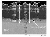
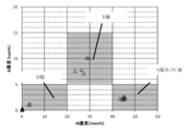
- FIG. 3 is a cross-sectional observation photograph of Fe—Al-based plating of a Fe—Al-based plated high-strength hot stamped steel sheet according to the invention of the present application, including A to D layers, Kirkendall voids, and FIGS. It is the figure which showed 4 EDS analysis points. It is a figure which shows Al and Fe composition of Fe-Al type
- An Fe—Al-based plated high-strength hot stamp member (hereinafter also simply referred to as “hot stamp member”) according to an embodiment of the present invention has an Fe—Al-based plated layer on one or both sides of a steel plate as a base material. have.
- the Vickers hardness (JIS Z 2244, load 9.8 N) of the hot stamp member according to the present embodiment is 300 HV or higher.
- the base material and the Fe—Al-based plating layer included in the hot stamp member according to the present embodiment will be described in detail.
- the base material of the hot stamp member according to the present embodiment has high hardenability. It must be a component system.
- the base material component of the hot stamp member is mass%, C: 0.1% to 0.5%, Si: 0.01% to 2.00%, Mn: 0.00. 3% to 5.0%, P: 0.001% to 0.100%, S: 0.001% to 0.100%, Al: 0.01% to 0.50%, Cr: It contains 0.01% or more and 2.00% or less, B: 0.0002% or more and 0.0100% or less, N: 0.001% or more and 0.010% or less, and the balance consists of Fe and impurities.
- the present invention provides a molded part (hot stamp member) having a high strength with a Vickers hardness of 300 HV or higher after hot stamping, and is rapidly cooled after hot stamping to transform into a structure mainly composed of martensite. Is required. Therefore, from the viewpoint of improving hardenability, the C (carbon) content needs to be at least 0.1% or more.
- the C content is preferably 0.15% or more.
- the C content is set to 0.5% or less.
- the C content is preferably 0.40% or less.
- Si 0.01% or more and 2.00% or less
- Si diffuses during plating by heating at the time of hot stamping, and has an effect of improving the corrosion resistance of the Fe—Al-based plating layer. Such an improvement in corrosion resistance is manifested when the Si content is 0.01% or more, so the Si content is 0.01% or more.
- the Si content is preferably 0.05% or more, and more preferably 0.1% or more.
- Si is an element (an easily oxidizable element) that is more easily oxidized than Fe. Therefore, in a continuous annealing plating line, a stable Si-based oxide film is formed on the surface of the steel sheet during the annealing process.
- the Si content is set to 2.0% or less.
- the Si content is preferably 1.80% or less, and more preferably 1.50% or less.
- Mn manganese
- Mn (manganese) diffuses during plating by heating during hot stamping, and has the effect of improving the corrosion resistance of the Fe—Al-based plating layer. Such an effect of improving the corrosion resistance is manifested when the Mn content is 0.3% or more, so the Mn content is 0.3% or more. Furthermore, by making the content of Mn 0.3% or more, the hardenability of the base material can be improved and the strength after hot stamping can be improved.
- the Mn content is preferably 0.5% or more, more preferably 0.7% or more.
- the impact characteristics of the member after quenching deteriorate. Such a decrease in impact characteristics occurs when the Mn content exceeds 5.0%, so the Mn content is 5.0% or less.
- the Mn content is preferably 3.0% or less, and more preferably 2.5% or less.
- P 0.001% to 0.100%
- P phosphorus
- the content of P is preferably 0.050% or less.
- the lower limit of the P content is not particularly limited, but if the P content is less than 0.001%, it is not economical from the viewpoint of the refining limit. Therefore, the P content is 0.001% or more.
- the content of P is preferably 0.005% or more.
- S sulfur
- S sulfur
- the content of S is preferably 0.010% or less.
- the lower limit of the S content is not particularly limited, but if the S content is less than 0.0001%, it is not economical from the viewpoint of the refining limit. Therefore, the content of S is set to 0.001% or more.
- the S content is preferably 0.0005% or more, and more preferably 0.001% or more.
- Al 0.01% to 0.50%
- Al aluminum
- Al is contained in steel as a deoxidizer.
- Al is an element (an easily oxidizable element) that is more easily oxidized than Fe.
- the content of Al is set to 0.50% or less from the viewpoint of suppressing non-plating.
- the Al content is preferably 0.30% or less.
- the lower limit of the Al content is not particularly limited, but if the Al content is less than 0.01%, it is not economical from the viewpoint of the refining limit. Therefore, the Al content is 0.01% or more.
- the Al content is preferably 0.02% or more.
- Cr 0.01% or more and 2.00% or less
- Cr has the effect of improving the hardenability of the steel sheet, like Mn. Such an effect of improving hardenability is manifested when the Cr content is 0.01% or more, so the Cr content is 0.01% or more. Further, when the Cr content is 0.01% or more, Cr diffuses during plating by heating at the time of hot stamping, and the effect of improving the corrosion resistance of the Fe—Al based plating layer is exhibited.
- the content of Cr is preferably 0.05% or more, and more preferably 0.1% or more.
- Cr is an element (an easily oxidizable element) that is more easily oxidized than Fe.
- the Cr content exceeds 2.0%, a stable Cr-based oxide film is formed on the surface of the steel sheet during the annealing process, which inhibits plating adhesion during the hot Al plating process and causes non-plating. Therefore, from the viewpoint of suppressing non-plating, the Cr content is set to 2.0% or less.
- the Cr content is preferably 1.00% or less.
- B boron
- B is a useful element from the viewpoint of hardenability, and when the B content is 0.0002% or more, the effect of improving the hardenability is exhibited. Therefore, the B content is set to 0.0002% or more.
- the content of B is preferably 0.0005% or more.
- the content of B is set to 0.0100% or less.
- the content of B is preferably 0.0050% or less.
- N nitrogen
- nitrogen is an element inevitably contained, and is preferably fixed in steel from the viewpoint of stabilizing the characteristics.
- N can be fixed with Al, Ti, Nb, or the like that is selectively contained.
- the N content is set to 0.010% or less.
- the N content is preferably 0.008% or less.
- the lower limit of the N content is not particularly limited, but if the N content is less than 0.001%, it is not economical from the viewpoint of the refining limit. Therefore, the N content is 0.001% or more.
- the N content is preferably 0.002% or more.
- W (tungsten) and Mo (molybdenum) are elements useful from the viewpoint of hardenability, and may be contained from the viewpoint of improving hardenability.
- the effect of improving the hardenability is manifested when the content of each element is 0.01% or more. Therefore, the W and Mo contents are each preferably 0.01% or more.
- the contents of W and Mo are each 3.00% or less. It is preferable to do.
- V vanadium
- V vanadium
- V vanadium
- the effect of improving the hardenability is manifested when the content of each element is 0.01% or more. However, even if V is contained in excess of 2.00%, the effect of improving the hardenability is saturated and the cost is increased, so the V content is preferably 2.00% or less. .
- Ti titanium
- Ti titanium
- the lower limit of the Ti content may be, for example, 0.005%.
- Ti when Ti is excessively contained, the hardenability is lowered and the strength is also lowered. Such a decrease in hardenability and strength becomes prominent when the Ti content exceeds 0.500%. Therefore, the Ti content is preferably 0.500% or less.
- Nb 0.01% or more and 1.00% or less
- Nb niobium
- Nb niobium
- the lower limit of the Nb content may be, for example, 0.01%.
- Nb when Nb is contained excessively, the hardenability is lowered and the strength is also lowered. Such a decrease in hardenability and strength becomes prominent when the Nb content exceeds 1.00%, so the Nb content is preferably 1.00% or less.
- Ni 0.01 to 5.00%
- Ni nickel
- the Ni content is preferably 0.01% or more.
- the Ni content is preferably 5.00% or less.
- Cu (copper) and Co (cobalt) are elements useful from the viewpoint of toughness in addition to hardenability, like Ni, and may be contained. Such effects of improving hardenability and toughness are manifested when the Cu and Co contents are each 0.01% or more. Therefore, the content of Cu and Co is preferably 0.01% or more. However, even if Cu and Co are contained in excess of 3.00%, such effects are saturated, and not only the cost is increased, but also deterioration of slab properties and cracks and flaws during hot rolling are caused. Therefore, the Cu and Co contents are preferably set to 3.00% or less.
- Sn (tin) and Sb (antimony) are both effective elements for improving the wettability and adhesion of plating, and may be contained.
- the effect of improving the wettability and adhesion of the plating is manifested when the content of each element is 0.005% or more. Therefore, the contents of Sn and Sb are each preferably 0.005% or more.
- the Sn content is preferably 0.300% or less, and the Sb content is preferably 0.100% or less.
- Ca 0.0001 to 0.01%, Mg: 0.0001 to 0.01%, Zr: 0.0001 to 0.01%, REM: 0.0001 to 0.01%
- Ca calcium
- Mg magnesium
- Zr zirconium
- REM Raster Metal: rare earth elements
- the contents of Ca, Mg, Zr, and REM are each preferably 0.0001% or more.
- the contents of Ca, Mg, Zr, and REM are each preferably 0.01% or less.
- the other components of the base material are not particularly specified.
- an element such as As (arsenic) may be mixed from scrap, but it does not affect the characteristics of the base material within the normal range.
- Fe-Al plating layer Next, the most important Fe—Al plating layer in the present invention will be described in detail.
- the thickness of the Fe—Al based plating layer according to this embodiment is 10 ⁇ m or more and 60 ⁇ m or less.
- the thickness of the Fe—Al based plating layer is less than 10 ⁇ m, the corrosion resistance of the molded part and the corrosion resistance after coating are lowered.
- the thickness of the Fe-Al plating layer exceeds 60 ⁇ m, the plating layer is thick, so the shearing force that the plating receives from the mold during hot stamping and the stress during compression deformation increase, and the plating layer peels off. As a result, the corrosion resistance of the molded part and the corrosion resistance after painting are lowered.
- the thickness of the Fe—Al based plating layer is preferably 15 ⁇ m or more, more preferably 20 ⁇ m or more.
- the thickness of the Fe—Al based plating layer is preferably 55 ⁇ m or less, more preferably 50 ⁇ m or less.
- Fe—Al-based plating layer means a plating layer made of an Fe—Al-based intermetallic compound and inevitably contained impurities.
- Specific examples of Fe—Al-based intermetallic compounds include Fe 2 Al 5 , FeAl 2 , FeAl (also referred to as ordered BCC), ⁇ -Fe (also referred to as irregular BCC), and Al solid solution ⁇ -. Fe, those in which Si is dissolved in these compositions, and the detailed stoichiometric composition may not be specified, but Al—Fe—Si ternary alloy compositions, etc.
- ⁇ 5 is also called an ⁇ phase
- ⁇ 6 is also called a ⁇ phase.
- the inevitable impurities contained in the Fe—Al-based plating layer include components such as stainless steel, ceramic, and a sprayed coating on these materials, which are generally used as a hot dipping equipment during hot dipping.
- Zn contained in the Fe—Al-based plating layer is preferably 10% by mass or less, for reasons of LME suppression during hot stamping described above, and preferably 3% by mass. The following is more preferable.
- the Fe—Al based plating layer as described above is composed of four layers of A layer, B layer, C layer, and D layer in order from the surface toward the base material.
- the lower layer of the D layer is a base material.
- SEM scanning Electron Microscope
- a martensitic structure is formed in the base material. Since it is not etched in this figure, it is not clear that it has a martensite structure. However, when the Vickers hardness (load 9.8 N) is measured, the hardness is HV400 or higher which suggests a martensite structure.
- the light gray contrast layer adjacent to the matrix is then the D layer.
- a layer formed on the surface side of the D layer and adjacent to the D layer and having a dark gray contrast is the C layer.
- the light gray contrast layer on the surface side adjacent to the C layer is the B layer, and the dark gray layer closest to the surface side adjacent to the B layer is the A layer.
- the B layer becomes intermittent and the A layer and the C layer may not be distinguished, but such a case is also within the scope of the present invention, and the corrosion resistance of the molded part and the corrosion resistance after coating There is no effect on the above.
- the contrast is an example, and if it is distinguished as four layers, it has a four-layer structure within the scope of the present application.
- Examples of the method for specifying the composition of each of the A layer, the B layer, the C layer, and the D layer constituting the Fe—Al plating layer include the following methods. That is, the cross section of the plating is polished and etching is not performed, and the composition is observed as a composition image with an electron beam microanalyzer (EPMA) at 1000 times from the cross section, and elemental analysis is performed. After identifying and distinguishing the A layer, the B layer, the C layer, and the D layer by the method described above, the composition analysis of each of the A layer, the B layer, the C layer, and the D layer is performed, and the total of Al, Fe, Si, Mn, and Cr It can obtain
- EPMA electron beam microanalyzer
- each of the A layer, B layer, C layer, and D layer is as follows. In addition,% of the following composition is the mass%, and each layer contains the component shown below so that the sum total may be 100 mass% or less, and the remainder becomes an impurity.
- a layer and C layer Al 40% by mass or more and 60% by mass or less Fe: 40% by mass or more and less than 60% by mass Si: 5% by mass or less (excluding 0% by mass) Mn: Less than 0.5% by mass (excluding 0% by mass) Cr: Less than 0.4% by mass (excluding 0% by mass)
- B layer Al 20 mass% or more and less than 40 mass% Fe: 50 mass% or more and less than 80 mass% Si: More than 5 mass% 15 mass% or less Mn: 0.5 mass% or more and 10 mass% or less Cr: 0.4 mass %
- the first role of the Fe—Al based plating layer is to improve the possibility of the corrosion resistance of the molded part.
- an Al-based plated steel sheet is used for hot stamping, it is exposed to a high temperature of 800 ° C. or higher, so that Fe diffuses to the surface of the plating, and the plated layer is hard and brittle between Fe-Al based metals. It changes to a Fe—Al based plating layer made of a compound. As a result, cracks and powder-like peeling occur in the plating during hot press molding, and the corrosion resistance of the molded part is lowered.
- the possibility regarding the corrosion resistance of the molded part is more specifically the occurrence of red rust from the bent R part of the molded part when the hat mold is corroded after being subjected to phosphorylation and electrodeposition coating after hot stamping. Is likely to be faster.
- the inventors of the present application have found that the red rust from the bent portion R of the molded part is caused by rust starting from cracks generated in the formation of the Fe-Al plating layer. It was. Further, the inventors of the present application for suppressing the occurrence of such rust, Al: 60% by mass or less for any of the composition of the A layer, the B layer, the C layer, and the D layer of the Fe—Al plating layer, and It has been found that Fe: 40 mass% or more and that it contains Si, Mn and Cr are important.
- Phosphorylation crystal is a crystal formed by general phosphorylation treatment in automobile parts, and improves the adhesion of electrodeposition coating after chemical conversion treatment, and as a result, improves corrosion resistance after coating. It is. Rust progresses from the surface, but as described above, from the viewpoint of the corrosion resistance of the molded part, it is rust starting from cracks generated in the Al—Fe-based plating layer. It is particularly important to control the layer and D layer to the above composition.
- the composition of the Fe—Al-based plating layer is Al: 60% by mass or less, Fe: 40% by mass or more, and further includes Si, Mn, and Cr, so that the reactivity of phosphorylation can be improved. Promoted.
- the cause of this is not yet clear, but by suppressing Al to 60% by mass or less and increasing Fe to 40% by mass or more, (1) destabilizing Al oxide formed during hot stamping (2)
- Si, Mn, and Cr in the plating act as crystal nuclei of the phosphorylation crystal, resulting in dense phosphorylation. It is presumed that the formation of a film of synthetic crystals had an influence on each.
- the second role of the Fe—Al plating layer is to improve the possibility of post-coating corrosion resistance.
- the possibility of post-coating corrosion resistance is that after hot stamping, a phosphorylation treatment and an electrodeposition coating treatment are performed, and wrinkles are applied to the coating film with a cutter (simulating wrinkles by chipping or the like). ), The corrosion blistering (Blister) of the coating film from the heel portion is likely to spread.
- the inventors of the present application have found that the spread of the corrosion swelling of the coating film from the buttock is caused by the decrease in the reactivity of the phosphorylation treatment and the corrosion of the Fe-Al plating layer. I found out. Further, the inventors of the present application, in order to suppress the cause, similarly to the possibility regarding the corrosion resistance of the molded part, the composition of the Fe—Al-based plating layer is Al: 60% by mass or less, Fe: 40% by mass or more, In addition to improving the reactivity of the phosphorylation treatment by containing Si, Mn, and Cr, the composition of the A layer, the B layer, the C layer, and the D layer is controlled to the above composition. Thus, it has been found that it is important to suppress corrosion of the Fe—Al based plating layer.
- the composition of the A layer, the B layer, the C layer, and the D layer here is specifically as described above.
- the composition of the A layer and the C layer is mass%, Al: 40% to 60%, Fe: 40% to less than 60%, Si: 5% or less (excluding 0%), Mn: 0.5 % (Not including 0%), Cr: less than 0.4% by mass (not including 0% by mass).
- the composition of the B layer is mass%, Al: 20% or more and less than 40%, Fe: 50% or more and less than 80%, Si: more than 5%, 15% or less, Mn: 0.5% or more and 10% or less, Cr: It is 0.4 mass% or more and 4 mass% or less.
- the composition of the D layer is mass%, Al: less than 20% (excluding 0%), Fe: 60% or more and less than 100%, Si: 5% or less (not including 0%), Mn: 0 0.5% to 2%, Cr: 0.4% to 4% by mass.
- the reason why the corrosion of the Fe—Al plating layer is suppressed by using the composition of the A layer, the B layer, the C layer, and the D layer as described above is not yet clear, but is estimated as follows. Yes. That is, the A layer and the C layer on the surface side of the D layer corrode relatively first, and further, the corrosion products of the A layer and the C layer act as a barrier layer against the progress of the subsequent corrosion. In addition, it is estimated that the corrosion swelling of the coating film on the buttock is suppressed. In particular, it is considered that containing Al sufficiently and suppressing excessive Fe, Si and Mn functions as a barrier layer that most suppresses the progress of corrosion.
- the composition of the A layer and the C layer is, by mass%, Al: 40% or more and 60% or less, Fe: 40% or more and less than 60%, Si: 5% or less (not including 0%), Mn: less than 0.5% (not including 0%), Cr: less than 0.4% by mass (0 mass) % Is not included.)
- the B layer and the D layer having a low Al content are electrochemically noble and are less susceptible to corrosion than the A layer and the C layer.
- B layer and D layer are not located in the outermost surface, as a result of a crack arising in plating in a shaping
- the composition of the D layer is less than 20% (not including 0%) by mass%. ), Fe: 60% to less than 100%, Si: 5% or less (excluding 0%), Mn: 0.5% to 2%, Cr: 0.4% to 4% by mass .
- the composition of Al and Fe is close to that of the A layer and the C layer, and further Si and Mn are contained, thereby protecting the oxides of Si and Mn. This suppresses corrosion of the B layer.
- the composition of the B layer is Al: 20% or more and less than 40%, Fe: 50% or more and 80%. %, Si: more than 5% and 15% or less, Mn: 0.5% to 10%, Cr: 0.4% to 4% by mass.
- the technology according to the present embodiment is provided by providing the B layer and the D layer which are relatively difficult to corrode, and the A layer and the C layer which are easily corroded but are expected to improve the corrosion resistance by the generated corrosion products. Has been completed.
- the area Kirkendall voids (sectional area) is 3 [mu] m 2 or more 30 [mu] m 2 or less (Kirkendall void) is contained 10/6000 .mu.m 2 or 40/6000 .mu.m 2 or less as the number density.
- Kirkendall void is contained 10/6000 .mu.m 2 or 40/6000 .mu.m 2 or less as the number density.
- the presence of Kirkendall void in the D layer reduces the stress concentration applied to the plating during hot stamping and suppresses the peeling of the plating, thereby improving the corrosion resistance of the molded part.
- Such an effect cannot be obtained when the number density of Kirkendall voids is less than 10/6000 ⁇ m 2 .
- the number density of Kirkendall voids exceeds 40/6000 ⁇ m 2 , it is rather the starting point of plating peeling during hot stamping.
- the number density of Kirkendall void is controlled as follows. That is, since the formation of Kirkendall void is caused by diffusion of Al and Fe, the number density of Kirkendall void increases as the maximum temperature of the steel sheet and the heating time during hot stamping increase. In addition, during heating at the time of hot stamping in which an alloying reaction occurs due to diffusion of Fe during plating, dY / dX, which will be described later, which is a gradient in the change over time in the heating rate becomes 0, Kirkendal The number density of voids can be controlled to a desired value.
- the longest diameter and the shortest diameter when the black observed particle is surrounded by an ellipse are measured, and half of the average value of the obtained long diameter and short diameter is treated as the radius r, which is given by ⁇ r 2.
- the value is the size of the area (cross-sectional area) of the Kirkendall void.
- Most of the cardendal voids are circular or elliptical, but in some cases, a plurality of cardendal voids may be in contact with each other during the growth process and become indefinite.
- the major and minor diameters are defined as the diameter of the smallest circumscribed circle that circumscribes the irregular Kirkendall void as the major axis and the diameter of the largest inscribed circle that is inscribed in the irregular Kirkendall void.
- the minor axis are defined as the diameter of the smallest circumscribed circle that circumscribes the irregular Kirkendall void as the major axis and the diameter of the largest inscribed circle that is inscribed in the irregular Kirkendall void.
- FIG. 5 shows an example in which the number density of the Kirkendall voids included in the D layer is obtained in the examples shown below.
- the oxide layer made of oxides of Mg and / or Ca is distinguished from the A layer, and is a layer containing 10% by mass or more of Mg and Ca in total. In the A layer, the total content of Mg and Ca is less than 10% by mass.
- the method for specifying the thickness and composition of the oxide layer composed of Mg and / or Ca oxide the obtained cross section was observed with EPMA without etching after the cross section of the plating was polished, as described above.
- the base material and the Fe—Al-based plating layer are as described above.
- the hot stamp member is used as an automobile part, Later, the final product is obtained through various processes such as welding, chemical conversion treatment, and electrodeposition coating.
- the chemical conversion treatment is usually subjected to phosphorylation treatment (chemical conversion treatment containing phosphorus and zinc as main components) or zirconium-based chemical conversion treatment (chemical conversion treatment containing zirconium as main components), and the hot stamp according to the present embodiment. Further, a chemical conversion treatment film accompanying these chemical conversion treatments is formed on the surface of the member.
- electrodeposition coating cationic electrodeposition coating (C is the main component) is usually applied to a film thickness of about 1 to 50 ⁇ m. After electrodeposition coating, intermediate coating, top coating, etc. May be applied.
- the film layer formed by these treatments and the A-layer, B-layer, C-layer, and D-layer of the Fe—Al-based plating layer can be easily identified and distinguished from the difference in the main components.
- the layer containing 40% by mass or more is defined as an Fe—Al-based plating layer.
- the slab (base material) is prepared by continuously casting after adjusting the chemical components in the steelmaking process so as to satisfy the chemical composition as described above. ), And then hot-rolling, pickling, and cold-rolling the resulting slab (base material) to form a cold-rolled steel sheet.
- the slab (base material) is prepared by continuously casting after adjusting the chemical components in the steelmaking process so as to satisfy the chemical composition as described above. ), And then hot-rolling, pickling, and cold-rolling the resulting slab (base material) to form a cold-rolled steel sheet.
- recrystallization annealing and hot-dip aluminum plating treatment to make an Al-plated steel sheet, blanking the obtained Al-plated steel sheet, and then continuously heating, forming, and rapidly cooling with a hot stamping equipment.
- the Fe—Al plating hot stamp member according to the embodiment is manufactured.
- the manufacturing method of the Fe—Al plating hot stamp member according to this embodiment will be described in detail.
- hot rolling is not particularly limited with respect to the steps until obtaining an Al-plated steel sheet.
- hot rolling is started at a heating temperature of 1300 ° C. or less (for example, within a range of 1000 to 1300 ° C.), and hot rolling is completed at around 900 ° C. (for example, within a range of 850 to 950 ° C.).
- the rate may be in the range of 60 to 90%.
- the winding temperature of the steel sheet after hot rolling as described above is not particularly limited, and may be, for example, in the range of 700 ° C. or higher and 850 ° C. or lower.
- the conditions for pickling the steel sheet after hot rolling are not particularly limited, and for example, hydrochloric acid pickling or sulfuric acid pickling may be used.
- the conditions of the cold rolling performed after the pickling as described above are not particularly limited, and for example, the rolling rate can be appropriately selected within a range of 30 to 90%.
- the obtained cold-rolled steel sheet is continuously subjected to recrystallization annealing and hot-dip aluminum plating in a hot dipping line to obtain an Al-plated steel sheet.
- the molten aluminum plating is performed by immersing in a molten aluminum plating bath and controlling the amount of aluminum plating attached by wiping.
- the composition of the molten aluminum plating bath is, by mass%, Al: 80% or more and 96% or less, Si: 3% or more and 15% or less, Fe: 1% or more and 5% or less so that the total is 100% by mass or less.
- the balance is impurities.
- Al is an element necessary for improving the oxidation resistance and corrosion resistance at the time of heating the hot stamp.
- the corrosion resistance of the plating is inferior, and the Al content is low. If it exceeds 96% by mass, the plating is easily peeled off during hot stamping, resulting in poor corrosion resistance.
- the content of Al in the molten aluminum plating bath is preferably 82% by mass or more.
- the content of Al in the molten aluminum plating bath is preferably 94% by mass or less.
- Si is an element necessary for improving the corrosion resistance of Fe—Al-based plating after hot stamping.
- Si content is less than 3% by mass, the corrosion resistance of the plating is inferior, and the Si content When the amount exceeds 15% by mass, non-plating occurs after the hot dipping process.
- the Si content in the molten aluminum plating bath is preferably 5% by mass or more.
- the Si content in the molten aluminum plating bath is preferably 12% by mass or less.
- Fe in the molten aluminum plating bath is inevitably contained due to the elution of Fe when the steel sheet is immersed, but is an element necessary for promoting the Fe content in the Fe—Al based plating.
- the content of Fe in the molten aluminum plating bath is preferably 2% by mass or more.
- the Fe content in the molten aluminum plating bath is preferably 4% by mass or less.
- Mg and / or Ca is contained in the molten aluminum plating bath in a total amount of 0.02 mass% or more and 3 mass% or less from the viewpoint of improving the corrosion resistance of the Fe—Al based plating.
- the total content of Mg and Ca is less than 0.02% by mass, the effect of improving corrosion resistance cannot be obtained.
- the total content of Mg and Ca exceeds 3% by mass, the excessive oxide produced causes a problem of non-plating during the hot dipping process.
- the total content of Mg and Ca in the molten aluminum plating bath is preferably 0.05% by mass or more and 2% by mass or less.
- the total content of Mg and Ca in the molten aluminum plating bath is more preferably 0.1% by mass or more.
- the total content of Mg and Ca in the molten aluminum plating bath is more preferably 1% by mass or less.
- Mg and / or Ca By adding Mg and / or Ca in a total amount of 0.02% by mass or more and 3% by mass or less to the molten aluminum plating bath, Mg and / or Ca is added to the plating layer before hot stamping in a total of 0. It becomes possible to contain 02 mass% or more and 3 mass% or less. Since Mg and Ca are very oxidizable elements, after hot stamping, Mg and / or Ca forms an oxide film on the surface of layer A of the Fe—Al based plating layer, and during Fe—Al based plating. Hardly remains. Further, the oxide film thus formed becomes an oxide layer made of the oxide of Mg and / or Ca described above.
- the film thickness of the oxide film formed after hot stamping can be controlled as follows. That is, the Mg and / or Ca oxide film is formed by diffusion and oxidation of Mg and / or Ca contained in the hot dipping bath to the plating surface by heating during hot stamping. Therefore, the thickness of the oxide film after hot stamping can be increased by increasing the contents of Mg and Ca in the plating bath. In addition, the longer the heating time during hot stamping, the higher the maximum plate temperature, the more the thickness of the oxide film after hot stamping can be increased. Depending on the content of Mg and Ca in the hot dipping bath The increase is likely to saturate.
- the conditions for the above wiping treatment are not particularly limited, but the aluminum plating layer is formed by controlling the amount of aluminum plating to be 30 g / m 2 or more and 120 g / m 2 or less per side. Is preferred.
- the adhesion amount of the aluminum plating is less than 30 g / m 2 per side, the corrosion resistance after hot stamping may be insufficient.
- the adhesion amount of the aluminum plating exceeds 120 g / m 2 per side, there may be a problem that the plating is peeled off when the hot stamp is formed.
- the adhesion amount of the aluminum plating per side is more preferably 40 g / m 2 or more.
- the adhesion amount of the aluminum plating per one side is more preferably 100 g / m 2 or less.
- Examples of the method for specifying the amount of aluminum plating attached include sodium hydroxide-hexamethylenetetramine / hydrochloric acid peeling weight method. Specifically, as described in JIS G 3314: 2011, a test piece having a predetermined area S (m 2 ) (for example, 50 mm ⁇ 50 mm) is prepared, and the weight w 1 (g) is measured. Then, after sequentially immersing in an aqueous solution of sodium hydroxide and an aqueous hydrochloric acid solution to which hexamethylenetetramine has been added until foaming has subsided, it is immediately washed with water and the weight w 2 (g) is measured again. At this time, the adhesion amount (g / m 2 ) of aluminum plating on both sides of the test piece can be obtained from (w 1 -w 2 ) / S.
- the steel plate to which aluminum plating is adhered (Al-plated steel plate) obtained as described above is continuously heated, formed, and rapidly cooled by a hot stamping facility after blanking. As a result, during heating, Fe diffuses to the surface of the aluminum plating, and an Fe—Al plating high strength hot stamp member is manufactured.
- the heating method is not particularly limited, and it is possible to use furnace heating using radiant heat, a near infrared method, a far infrared method, a heating method such as induction heating or current heating, and the like. is there.
- the hot stamp member according to the present embodiment when the hot stamp member according to the present embodiment is manufactured, the time from when the blanked Al-plated steel sheet is put into heating equipment such as a heating furnace as described above until it is taken out is referred to as heating time. I will do it.
- the heating time does not include the conveyance time after the Al-plated steel sheet is taken out from the heating equipment or the hot forming time as described below.
- the heating time is controlled to be 150 seconds or longer and 650 seconds or shorter. If the heating time from when the blanked Al-plated steel sheet is put into the heating equipment to when it is taken out is less than 150 seconds, the diffusion of Fe into the Al plating is insufficient and soft Al remains. It is not preferable because it is inferior to the corrosion resistance of the molded product and the corrosion resistance after coating.
- the heating time from when the blanked Al-plated steel sheet is put into the heating equipment to when it is taken out is preferably 200 seconds or more, and more preferably 250 seconds or more. Further, the heating time from when the blanked Al-plated steel sheet is put into the heating equipment to when it is taken out is preferably 600 seconds or less, and more preferably 550 seconds or less.
- the maximum reached plate temperature of the Al-plated steel plate is set to 850 ° C. or higher and 1050 ° C. or lower.
- the reason why the maximum plate temperature is 850 ° C. or higher is that the steel sheet is heated to the Ac1 point or higher so that the martensite is transformed at the time of rapid cooling in the mold, the base material is strengthened, and the plating surface is sufficient. This is because the Fe plating is diffused into the alloy to advance the alloying of the Al plating layer.
- the highest reached plate temperature of the Al-plated steel plate is more preferably 910 ° C or higher.
- the highest attained plate temperature of the Al-plated steel plate is more preferably 980 ° C. or lower.
- the Al plated steel sheet in a heated state is hot stamped into a predetermined shape between a pair of upper and lower forming dies.
- the steel plate is quenched and quenched by contact cooling with the molding die, and the hot stamped high strength member according to the present embodiment is obtained.
- the average cooling rate at the time of rapid cooling to 30 ° C./second or more, the martensitic transformation is sufficiently advanced to achieve high strength of the base material.
- the Vickers hardness (load 9.8 N) of the base material becomes 300 HV or more.
- the upper limit of the average cooling rate at the time of rapid cooling is not particularly limited, and the faster the better, but the upper limit is substantially about 1000 ° C./second.
- the average cooling rate (° C./s) is measured, for example, by using a thermocouple or a radiation thermometer to measure the time t 0 (seconds) required for the steel sheet temperature to be rapidly cooled from 800 ° C. to 200 ° C. or less. Then, from the obtained time t 0 (second), it can be obtained as (800 ⁇ 200) / t 0 .
- the steel plate temperature Y (° C.) and the heating time X (seconds) in heating are controlled so that the heating time X when the steel plate temperature Y is 600 ° C. or higher and 800 ° C. or lower is 100 seconds or longer and 300 seconds or shorter. .
- the heating time X and the steel plate temperature Y within the above ranges, the diffusion of Fe during plating is controlled, and the Al-plated steel plate is a hot stamping member that has excellent corrosion resistance after forming and corrosion resistance after coating.
- the said steel plate temperature Y is less than 600 degreeC, or when it exceeds 800 degreeC, a shaping
- the heating time X when the steel plate temperature Y is 600 ° C. or more and 800 ° C. or less is preferably 120 seconds or more, and more preferably 150 seconds or more.
- the heating time X when the steel plate temperature Y is 600 ° C. or higher and 800 ° C. or lower is preferably 280 seconds or shorter, and more preferably 250 seconds or shorter.
- the steel plate temperature Y in heating when the first derivative (dY / dX) regarding the heating time X of the steel plate temperature Y is 0, the steel plate temperature Y is in the range of 600 ° C. or higher and 800 ° C. or lower. Control.
- the first derivative (dY / dX) is zero, there is an extreme value during the time transition of the steel sheet temperature Y, and it exists in a temperature range of 600 ° C. or more and 800 ° C. or less, which is important for Fe diffusion during plating. As a result, the diffusion time of Fe can be more reliably controlled.
- the meaning of “more reliable control” it is not only important that the time is 600 ° C. or more and 800 ° C.
- the elements Mn and Cr that are difficult to be contained in the A layer and the C layer are discharged from the A layer and the C layer that are being formed to the outside of the layer. Then, the B layer and D layer that are being formed are concentrated. Therefore, the content of Mn and Cr contained in the B layer and the D layer may be larger than the contents of Mn and Cr contained in the steel plate. Since the above diffusion phenomenon occurs between 600 and 800 ° C., in order to control the diffusion of elements, it is necessary to control the first derivative (dY / dX) in addition to the material heating time at 600 to 800 ° C. is there. Ultimately, it is presumed that the composition of the A layer to the D layer as described above is realized at the stage of the Fe—Al plating hot stamp member after heating.
- the number of times the first derivative (dY / dX) becomes 0 in the range where the steel sheet temperature Y is 600 ° C. or higher and 800 ° C. or lower is not particularly limited. For example, if the temperature is kept constant at 700 ° C., the number of times that the first derivative (dY / dX) becomes zero is one. As another example, heating is performed in a furnace at 900 ° C., and after reaching 700 ° C. in the middle of the temperature increase, the furnace is immediately moved to a heating furnace at 600 ° C. and held until the plate temperature reaches 600 ° C. If a method of heating in a furnace at 0 ° C.
- the number of times that the first derivative (dY / dX) becomes zero is two.
- the number of times that the first derivative (dY / dX) is 0 is not particularly limited as long as it is 1 or more, but it is 3 or less because manufacturing equipment becomes complicated and expensive. Is preferred.
- the steel plate temperature Y in heating is obtained by spot-welding a K-type thermocouple to a 300 mm ⁇ 300 mm steel plate and measuring the steel plate temperature during heating.
- the steel plate temperature at this time is sampled at a time interval of 0.1 seconds and digitized.
- the first derivative (dY / dX) of the steel sheet temperature Y is measured at an interval of 0.1 seconds, when the steel sheet temperature at a certain point in time is Y1, and the steel sheet temperature after 0.1 seconds is Y2, It can be obtained from (Y2-Y1) /0.1.
- the hot stamp member becomes a final part after post-processing such as welding, chemical conversion treatment, and electrodeposition coating.
- chemical conversion treatment a zinc phosphate-based film or a zirconium-based film is usually applied.
- cationic electrodeposition is often used as the electrodeposition coating, and the film thickness is about 5 to 50 ⁇ m.
- coating such as intermediate coating and top coating may be further applied to improve the appearance quality and corrosion resistance.
- Fe—Al plating hot stamp member and the manufacturing method thereof according to the present invention will be described more specifically with reference to examples.
- the following embodiment is merely an example of the Fe—Al plating hot stamp member and the manufacturing method thereof according to the present invention, and the Fe—Al plating hot stamp member and the manufacturing method thereof according to the present invention are the following examples. It is not limited to.
- Example 1 Using cold-rolled steel sheets (thickness: 1.4 mm) with steel components as shown in Table 1 below, the recrystallization annealing and hot-dip aluminum plating treatment are performed continuously through the hot rolling process and the cold rolling process. Went.
- Table 1 the mass ratio of Al, Fe, and Si having a relatively large content is expressed as an integer by rounding off.
- the coiling temperature during hot rolling is set to 700 ° C or higher and 800 ° C or lower.
- hot-dip Al plating a non-oxidizing furnace-reducing furnace type line is used, and the amount of plating deposited is about 30 g / side by gas wiping after plating.
- the aluminum plating bath composition at this time was Al-2% Fe, and Si was 3% or more and 15%.
- a high strength hot stamp member was obtained by quenching at a cooling rate of at least ° C./second and holding time at the bottom dead center of 10 seconds.
- A: dY / dX 0, heating time: 500 seconds, maximum plate temperature: 950 ° C., heating time from 600 ° C. to 800 ° C.
- heating time 300 seconds
- Maximum reached plate temperature: 850 ° C. heating time at 600 ° C. to 800 ° C.
- thermocouple was spot-welded to an Al-plated steel plate blanked to 240 mm ⁇ 300 mm in advance, and the steel plate temperature during heating was measured.
- the heating time X when the steel plate temperature Y is 600 ° C. or higher and 800 ° C. or lower is as shown in Tables 2-1 and 2-2 below.
- the thickness of the Fe—Al plating layer and the composition of the A layer, the B layer, the C layer, and the D layer were set. It was specified by analyzing with EPMA according to the method described above.
- the D layer the number of Kirkendall voids having a cross-sectional area of 3 ⁇ m 2 or more and 30 ⁇ m 2 or less was measured according to the method described above.
- FIGS. 2, 3 and 4 show the results of analyzing the points marked “+” from the cross-sectional image shown in FIG.
- compositions of the A layer, the B layer, the C layer, and the D layer are summarized in Table 2-1 below. No. shown in Table 2-2 Samples 20 to 22 did not have a four-layer structure of A layer, B layer, C layer, and D layer as noted in the present invention, so the detailed composition of each layer was not specified.
- the corrosion resistance after molding and the corrosion resistance after painting were evaluated according to the following criteria.
- the molded part corrosion resistance was evaluated by the following procedure.
- Each of the hat molded products with a bending R 5 mm, which is a hot stamp member manufactured according to the above procedure, was subjected to chemical conversion treatment using a chemical conversion treatment solution PB-SX35T manufactured by Nippon Parkerizing Co., Ltd., and then Nippon Paint Co., Ltd. ) Cationic electrodeposition paint Powernics 110 made in a thickness of about 10 ⁇ m.
- a composite corrosion test (JASO M610-92) determined by the automobile engineering association was performed for 60 cycles (20 days), and the presence or absence of red rust in the R part of the molded product was confirmed.
- the corrosion resistance after painting was evaluated by the following procedure. Similarly, each of the manufactured hat molded products was subjected to a chemical conversion treatment with a chemical conversion treatment solution PB-SX35T manufactured by Nihon Parkerizing Co., Ltd., and then a cationic electrodeposition paint Powernics 110 manufactured by Nihon Paint Co., Ltd. of about 10 ⁇ m Painted with thickness. After that, the vertical wall part of the molded product was cross-cut into the coating film with a cutter, and the composite corrosion test (JASO M610-92) determined by the Japan Automobile Technical Association was carried out for 180 cycles (60 days). The swollen width was measured.
- an alloyed hot-dip galvanized steel sheet (GA: adhesion amount single side 45 g / m 2 ) was used as a comparative material, and the same chemical conversion treatment, electrodeposition coating film, and crosscut as those described above were tested.
- GA adhesion amount single side 45 g / m 2
- B Bad
- G Good
- Example 2 When obtaining a hot stamp member by the same production method as in Example 1, the result of obtaining a hot stamp member by adding 0.02% by mass or more and 2% by mass or less of Mg or Ca as a plating bath composition is as follows. Table 3 shows. Here, the condition “A” in Example 1 was adopted as the heat treatment condition. The results of examining the thickness of the oxide layer made of an oxide of Mg or Ca by a cross-sectional SEM are shown in Table 3 below. The evaluation criteria for the corrosion resistance of the molded part and the corrosion resistance after painting are the same as in Example 1.
- Example 3 As in Example 1, a cold rolled steel sheet (thickness: 1.4 mm) having the steel components shown in Table 1 was used as a test material, and it was continuously subjected to recrystallization annealing and melting through a hot rolling process and a cold rolling process. Aluminum plating was performed. The coiling temperature during hot rolling is set to 700 ° C or higher and 800 ° C or lower. For hot-dip Al plating, a non-oxidizing furnace-reducing furnace type line is used, and the amount of plating deposited is about 30 g / side by gas wiping after plating. m 2 or more 120 g / m 2 was adjusted so as to become less, and then cooled. The plating bath composition at this time is shown in Table 4 below.
- the obtained Al-plated steel sheet was blanked to 240 mm ⁇ 300 mm, heated, and then heated under the conditions shown as heat treatment condition A of Example 1 for hot stamping, molded into a hat shape, 50 ° C. / The sheet was rapidly cooled at a cooling rate of at least 2 seconds, and the holding time at the bottom dead center was 10 seconds to obtain a high strength hot stamp member.
- thermocouple was spot-welded to an Al-plated steel plate blanked to 240 mm ⁇ 300 mm in advance, and the steel plate temperature during heating was measured.
- Table 6 Detailed manufacturing conditions are shown in Table 6 below.
- the hot stamp member thus produced was evaluated for corrosion resistance after molding and corrosion resistance after painting according to the same criteria as in Example 1, and the obtained results are shown in Table 4 below.
- strength hot stamp member excellent in the corrosion resistance after coating, and its manufacturing method can be provided, the improvement of automobile collision safety, the improvement in fuel consumption by weight reduction of an automobile, and CO 2. It leads to reduction of exhaust gas.
Landscapes
- Chemical & Material Sciences (AREA)
- Engineering & Computer Science (AREA)
- Mechanical Engineering (AREA)
- Materials Engineering (AREA)
- Metallurgy (AREA)
- Organic Chemistry (AREA)
- Chemical Kinetics & Catalysis (AREA)
- Physics & Mathematics (AREA)
- Thermal Sciences (AREA)
- Crystallography & Structural Chemistry (AREA)
- Oil, Petroleum & Natural Gas (AREA)
- Coating With Molten Metal (AREA)
- Heat Treatment Of Sheet Steel (AREA)
- Heat Treatment Of Articles (AREA)
- Shaping Metal By Deep-Drawing, Or The Like (AREA)
Priority Applications (7)
| Application Number | Priority Date | Filing Date | Title |
|---|---|---|---|
| CA3090649A CA3090649A1 (en) | 2018-02-15 | 2019-02-15 | Fe-a1-based plated hot-stamped member and manufacturing method of fe-a1-based plated hot-stamped member |
| JP2019543396A JP6607338B1 (ja) | 2018-02-15 | 2019-02-15 | Fe−Al系めっきホットスタンプ部材及びFe−Al系めっきホットスタンプ部材の製造方法 |
| CN201980002120.6A CN110573644B (zh) | 2018-02-15 | 2019-02-15 | Fe-Al系镀覆热冲压构件和Fe-Al系镀覆热冲压构件的制造方法 |
| EP19755186.4A EP3623493B1 (en) | 2018-02-15 | 2019-02-15 | Fe-al plated hot-stamped member and method for producing fe-al plated hot-stamped member |
| MX2020005505A MX2020005505A (es) | 2018-02-15 | 2019-02-15 | Miembro estampado en caliente enchapado a base de fe-al y metodo de fabricacion del miembro estampado en caliente a base de fe-al. |
| US16/634,346 US11530474B2 (en) | 2018-02-15 | 2019-02-15 | Fe—Al-based plated hot-stamped member and manufacturing method of Fe—Al-based plated hot-stamped member |
| KR1020207018354A KR102426324B1 (ko) | 2018-02-15 | 2019-02-15 | Fe-Al계 도금 핫 스탬프 부재 및 Fe-Al계 도금 핫 스탬프 부재의 제조 방법 |
Applications Claiming Priority (2)
| Application Number | Priority Date | Filing Date | Title |
|---|---|---|---|
| JP2018-025328 | 2018-02-15 | ||
| JP2018025328 | 2018-02-15 |
Publications (1)
| Publication Number | Publication Date |
|---|---|
| WO2019160106A1 true WO2019160106A1 (ja) | 2019-08-22 |
Family
ID=67620194
Family Applications (1)
| Application Number | Title | Priority Date | Filing Date |
|---|---|---|---|
| PCT/JP2019/005659 Ceased WO2019160106A1 (ja) | 2018-02-15 | 2019-02-15 | Fe-Al系めっきホットスタンプ部材及びFe-Al系めっきホットスタンプ部材の製造方法 |
Country Status (10)
| Country | Link |
|---|---|
| US (1) | US11530474B2 (https=) |
| EP (1) | EP3623493B1 (https=) |
| JP (1) | JP6607338B1 (https=) |
| KR (1) | KR102426324B1 (https=) |
| CN (1) | CN110573644B (https=) |
| CA (1) | CA3090649A1 (https=) |
| IN (1) | IN202017021813A (https=) |
| MX (1) | MX2020005505A (https=) |
| TW (1) | TWI682066B (https=) |
| WO (1) | WO2019160106A1 (https=) |
Cited By (10)
| Publication number | Priority date | Publication date | Assignee | Title |
|---|---|---|---|---|
| WO2022014645A1 (ja) * | 2020-07-14 | 2022-01-20 | 日本製鉄株式会社 | ホットスタンプ部材およびその製造方法 |
| KR20230022425A (ko) * | 2020-06-08 | 2023-02-15 | 아이어노베이션 머티리얼스 테크놀러지 씨오., 엘티디. | 얇은 알루미늄 합금 코팅을 갖는 코팅된 스틸 시트 및 그 코팅 방법 |
| JP2023547428A (ja) * | 2020-12-18 | 2023-11-10 | ポスコ カンパニー リミテッド | 耐水素脆性及び耐衝突性に優れた熱間成形用めっき鋼板、熱間成形部材及びそれらの製造方法 |
| KR20230169265A (ko) | 2021-07-14 | 2023-12-15 | 닛폰세이테츠 가부시키가이샤 | Al 도금 강판, Al 도금 강판의 제조 방법, 및 핫 스탬프 성형체의 제조 방법 |
| US20240068080A1 (en) * | 2021-04-05 | 2024-02-29 | Nippon Steel Corporation | Hot-stamped product |
| JP2025000732A (ja) * | 2021-04-06 | 2025-01-07 | 日本製鉄株式会社 | ホットスタンプ部材 |
| JP2025011114A (ja) * | 2021-04-06 | 2025-01-23 | 日本製鉄株式会社 | ホットスタンプ部材 |
| JP7642164B1 (ja) | 2023-06-30 | 2025-03-07 | アルセロールミタル | 優れたスポット溶接性および優れた塗装付着性を有する亀裂含有ホットスタンプされた被覆鋼部品 |
| JP7642163B1 (ja) | 2023-06-30 | 2025-03-07 | アルセロールミタル | 優れたスポット溶接性および優れた塗装付着性を有する、薄いコーティングを有する亀裂含有ホットスタンプ鋼部品 |
| JP2025507310A (ja) * | 2022-05-06 | 2025-03-18 | ポスコ カンパニー リミテッド | 熱間プレス成形部材及びその製造方法 |
Families Citing this family (7)
| Publication number | Priority date | Publication date | Assignee | Title |
|---|---|---|---|---|
| KR102330812B1 (ko) * | 2020-06-30 | 2021-11-24 | 현대제철 주식회사 | 열간 프레스용 강판 및 이의 제조 방법 |
| CN111778467B (zh) | 2020-09-04 | 2020-11-24 | 育材堂(苏州)材料科技有限公司 | 带铝或铝合金预镀层的预镀层钢板、制造方法及热冲压成形构件 |
| CN113802065B (zh) * | 2021-11-18 | 2022-03-29 | 育材堂(苏州)材料科技有限公司 | 热冲压成形构件、热冲压成形用钢板以及热冲压工艺 |
| CN114561589A (zh) * | 2022-02-28 | 2022-05-31 | 北京理工大学重庆创新中心 | 一种添加y元素的无涂层抗高温氧化热冲压成形钢 |
| CN115820991B (zh) * | 2022-11-11 | 2024-06-21 | 唐山钢铁集团有限责任公司 | 一种防止铝硅镀层产品热处理过程中镀层粘辊的方法 |
| WO2025135805A1 (ko) * | 2023-12-18 | 2025-06-26 | 주식회사 포스코 | 열간성형용 도금강판 및 그 제조방법과 열간 프레스 성형 부재의 제조방법 |
| KR20250094136A (ko) * | 2023-12-18 | 2025-06-25 | 주식회사 포스코 | 열간 프레스 성형 부재 및 이의 제조방법 |
Citations (7)
| Publication number | Priority date | Publication date | Assignee | Title |
|---|---|---|---|---|
| JPH09202953A (ja) | 1996-01-25 | 1997-08-05 | Nisshin Steel Co Ltd | Fe−Al−Si合金層を形成した熱器具用鋼材およびその製造方法 |
| JP2003181549A (ja) | 2001-08-31 | 2003-07-02 | Nippon Steel Corp | アルミ系めっき鋼板を用いた高強度自動車部材の熱間プレス方法 |
| JP2007314874A (ja) | 2006-04-25 | 2007-12-06 | Nippon Steel Corp | 高強度自動車部品およびその熱間プレス方法 |
| JP2008285757A (ja) * | 2008-05-27 | 2008-11-27 | Nippon Steel Corp | 塗装後耐食性に優れた高強度自動車部品 |
| JP2009263692A (ja) | 2008-04-22 | 2009-11-12 | Nippon Steel Corp | ホットプレス部材及びその製造方法 |
| WO2017017905A1 (ja) * | 2015-07-29 | 2017-02-02 | Jfeスチール株式会社 | 熱間プレス部材の製造方法 |
| WO2017111525A1 (ko) * | 2015-12-23 | 2017-06-29 | 주식회사 포스코 | 내수소지연파괴특성, 내박리성 및 용접성이 우수한 열간성형용 알루미늄-철 합금 도금강판 및 이를 이용한 열간성형 부재 |
Family Cites Families (13)
| Publication number | Priority date | Publication date | Assignee | Title |
|---|---|---|---|---|
| CN100370054C (zh) * | 2001-06-15 | 2008-02-20 | 新日本制铁株式会社 | 镀有铝合金体系的高强度钢板以及具有优异的耐热性和喷漆后耐腐蚀性的高强度汽车零件 |
| JP3738754B2 (ja) | 2002-07-11 | 2006-01-25 | 日産自動車株式会社 | 電着塗装用アルミニウムめっき構造部材及びその製造方法 |
| JP4446428B2 (ja) | 2003-02-17 | 2010-04-07 | 新日本製鐵株式会社 | 塗装後耐食性に優れた高強度自動車部品 |
| JP4410718B2 (ja) * | 2005-04-25 | 2010-02-03 | 新日本製鐵株式会社 | 塗料密着性、塗装後耐食性に優れたAl系めっき鋼板及びこれを用いた自動車部材並びにAl系めっき鋼板の製造方法 |
| BRPI0622071A2 (pt) * | 2006-10-30 | 2014-05-27 | Arcelormittal France | Tiras de aço revestidas, métodos de produção da mesma, métodos de uso das mesmas, discos de estampagem preparados a partir das mesmas, e produtos que contenham tal produto estampado |
| WO2009090443A1 (en) * | 2008-01-15 | 2009-07-23 | Arcelormittal France | Process for manufacturing stamped products, and stamped products prepared from the same |
| JP5224010B2 (ja) | 2010-10-22 | 2013-07-03 | 新日鐵住金株式会社 | 縦壁部を有するホットスタンプ成形体の製造方法及び縦壁部を有するホットスタンプ成形体 |
| KR101829854B1 (ko) | 2011-04-01 | 2018-02-20 | 신닛테츠스미킨 카부시키카이샤 | 도장 후 내식성이 우수한 핫 스탬핑 성형된 고강도 부품 및 그 제조 방법 |
| CA2865910C (en) | 2012-03-07 | 2017-10-17 | Nippon Steel & Sumitomo Metal Corporation | Steel sheet for hot stamping, method for production thereof, and hot stamping steel material |
| EP2980262A4 (en) | 2013-04-18 | 2016-11-23 | Nippon Steel & Sumitomo Metal Corp | PLATED STEEL PLATE FOR HOT PRESSING, METHOD FOR HOT PRESSING A PLATED STEEL PLATE AND AUTOMOTIVE PARTS |
| TWI588293B (zh) * | 2016-05-10 | 2017-06-21 | 新日鐵住金股份有限公司 | 熱壓印成形體 |
| WO2018142534A1 (ja) | 2017-02-02 | 2018-08-09 | 新日鐵住金株式会社 | ホットスタンプ用合金化Alめっき鋼板およびホットスタンプ部材 |
| MX2019011731A (es) * | 2017-03-31 | 2019-11-21 | Nippon Steel Corp | Cuerpo estampado en caliente. |
-
2019
- 2019-02-15 IN IN202017021813A patent/IN202017021813A/en unknown
- 2019-02-15 TW TW108105203A patent/TWI682066B/zh not_active IP Right Cessation
- 2019-02-15 US US16/634,346 patent/US11530474B2/en active Active
- 2019-02-15 WO PCT/JP2019/005659 patent/WO2019160106A1/ja not_active Ceased
- 2019-02-15 EP EP19755186.4A patent/EP3623493B1/en active Active
- 2019-02-15 JP JP2019543396A patent/JP6607338B1/ja active Active
- 2019-02-15 CN CN201980002120.6A patent/CN110573644B/zh active Active
- 2019-02-15 CA CA3090649A patent/CA3090649A1/en not_active Abandoned
- 2019-02-15 MX MX2020005505A patent/MX2020005505A/es unknown
- 2019-02-15 KR KR1020207018354A patent/KR102426324B1/ko active Active
Patent Citations (7)
| Publication number | Priority date | Publication date | Assignee | Title |
|---|---|---|---|---|
| JPH09202953A (ja) | 1996-01-25 | 1997-08-05 | Nisshin Steel Co Ltd | Fe−Al−Si合金層を形成した熱器具用鋼材およびその製造方法 |
| JP2003181549A (ja) | 2001-08-31 | 2003-07-02 | Nippon Steel Corp | アルミ系めっき鋼板を用いた高強度自動車部材の熱間プレス方法 |
| JP2007314874A (ja) | 2006-04-25 | 2007-12-06 | Nippon Steel Corp | 高強度自動車部品およびその熱間プレス方法 |
| JP2009263692A (ja) | 2008-04-22 | 2009-11-12 | Nippon Steel Corp | ホットプレス部材及びその製造方法 |
| JP2008285757A (ja) * | 2008-05-27 | 2008-11-27 | Nippon Steel Corp | 塗装後耐食性に優れた高強度自動車部品 |
| WO2017017905A1 (ja) * | 2015-07-29 | 2017-02-02 | Jfeスチール株式会社 | 熱間プレス部材の製造方法 |
| WO2017111525A1 (ko) * | 2015-12-23 | 2017-06-29 | 주식회사 포스코 | 내수소지연파괴특성, 내박리성 및 용접성이 우수한 열간성형용 알루미늄-철 합금 도금강판 및 이를 이용한 열간성형 부재 |
Cited By (23)
| Publication number | Priority date | Publication date | Assignee | Title |
|---|---|---|---|---|
| JP7648196B2 (ja) | 2020-06-08 | 2025-03-18 | 育材堂(▲蘇▼州)材料科技有限公司 | 薄いアルミニウム合金めっきを有するめっき鋼板およびそのめっき方法 |
| KR20230022425A (ko) * | 2020-06-08 | 2023-02-15 | 아이어노베이션 머티리얼스 테크놀러지 씨오., 엘티디. | 얇은 알루미늄 합금 코팅을 갖는 코팅된 스틸 시트 및 그 코팅 방법 |
| JP2023538178A (ja) * | 2020-06-08 | 2023-09-07 | 育材堂(▲蘇▼州)材料科技有限公司 | 薄いアルミニウム合金めっきを有するめっき鋼板およびそのめっき方法 |
| KR102803662B1 (ko) | 2020-06-08 | 2025-05-07 | 아이어노베이션 머티리얼스 테크놀러지 씨오., 엘티디. | 얇은 알루미늄 합금 코팅을 갖는 코팅된 스틸 시트 및 그 코팅 방법 |
| US12331407B2 (en) | 2020-06-08 | 2025-06-17 | Ironovation Materials Technology Co., Ltd. | Coated steel sheet with thin aluminium alloy coating and coating method thereof |
| JPWO2022014645A1 (https=) * | 2020-07-14 | 2022-01-20 | ||
| JP7260840B2 (ja) | 2020-07-14 | 2023-04-19 | 日本製鉄株式会社 | ホットスタンプ部材およびその製造方法 |
| WO2022014645A1 (ja) * | 2020-07-14 | 2022-01-20 | 日本製鉄株式会社 | ホットスタンプ部材およびその製造方法 |
| JP7693802B2 (ja) | 2020-12-18 | 2025-06-17 | ポスコ カンパニー リミテッド | 耐水素脆性及び耐衝突性に優れた熱間成形用めっき鋼板、熱間成形部材及びそれらの製造方法 |
| US12084734B2 (en) | 2020-12-18 | 2024-09-10 | Posco Co., Ltd | Plated steel sheets for hot press forming having excellent hydrogen brittleness resistance and impact resistance, hot press formed parts, and manufacturing methods thereof |
| JP2023547428A (ja) * | 2020-12-18 | 2023-11-10 | ポスコ カンパニー リミテッド | 耐水素脆性及び耐衝突性に優れた熱間成形用めっき鋼板、熱間成形部材及びそれらの製造方法 |
| US20240068080A1 (en) * | 2021-04-05 | 2024-02-29 | Nippon Steel Corporation | Hot-stamped product |
| US12404575B2 (en) * | 2021-04-05 | 2025-09-02 | Nippon Steel Corporation | Hot-stamped product |
| JP2025011114A (ja) * | 2021-04-06 | 2025-01-23 | 日本製鉄株式会社 | ホットスタンプ部材 |
| JP2025000732A (ja) * | 2021-04-06 | 2025-01-07 | 日本製鉄株式会社 | ホットスタンプ部材 |
| JP7773086B2 (ja) | 2021-04-06 | 2025-11-19 | 日本製鉄株式会社 | ホットスタンプ部材 |
| JP7773087B2 (ja) | 2021-04-06 | 2025-11-19 | 日本製鉄株式会社 | ホットスタンプ部材 |
| KR20230169265A (ko) | 2021-07-14 | 2023-12-15 | 닛폰세이테츠 가부시키가이샤 | Al 도금 강판, Al 도금 강판의 제조 방법, 및 핫 스탬프 성형체의 제조 방법 |
| JP2025507310A (ja) * | 2022-05-06 | 2025-03-18 | ポスコ カンパニー リミテッド | 熱間プレス成形部材及びその製造方法 |
| JP2025512210A (ja) * | 2023-06-30 | 2025-04-17 | アルセロールミタル | 優れたスポット溶接性および優れた塗装付着性を有する亀裂含有ホットスタンプされた被覆鋼部品 |
| JP2025512209A (ja) * | 2023-06-30 | 2025-04-17 | アルセロールミタル | 優れたスポット溶接性および優れた塗装付着性を有する、薄いコーティングを有する亀裂含有ホットスタンプ鋼部品 |
| JP7642163B1 (ja) | 2023-06-30 | 2025-03-07 | アルセロールミタル | 優れたスポット溶接性および優れた塗装付着性を有する、薄いコーティングを有する亀裂含有ホットスタンプ鋼部品 |
| JP7642164B1 (ja) | 2023-06-30 | 2025-03-07 | アルセロールミタル | 優れたスポット溶接性および優れた塗装付着性を有する亀裂含有ホットスタンプされた被覆鋼部品 |
Also Published As
| Publication number | Publication date |
|---|---|
| EP3623493B1 (en) | 2023-12-20 |
| TW201934779A (zh) | 2019-09-01 |
| CA3090649A1 (en) | 2019-08-22 |
| EP3623493A4 (en) | 2020-12-23 |
| US20210095368A1 (en) | 2021-04-01 |
| EP3623493A1 (en) | 2020-03-18 |
| JP6607338B1 (ja) | 2019-11-20 |
| MX2020005505A (es) | 2020-09-03 |
| CN110573644A (zh) | 2019-12-13 |
| KR102426324B1 (ko) | 2022-07-29 |
| CN110573644B (zh) | 2021-07-16 |
| IN202017021813A (https=) | 2020-08-21 |
| US11530474B2 (en) | 2022-12-20 |
| KR20200092352A (ko) | 2020-08-03 |
| JPWO2019160106A1 (ja) | 2020-02-27 |
| TWI682066B (zh) | 2020-01-11 |
Similar Documents
| Publication | Publication Date | Title |
|---|---|---|
| JP6607338B1 (ja) | Fe−Al系めっきホットスタンプ部材及びFe−Al系めっきホットスタンプ部材の製造方法 | |
| CN111511942B (zh) | 镀铝系钢板、镀铝系钢板的制造方法及汽车用部件的制造方法 | |
| WO2018221738A1 (ja) | ホットスタンプ部材 | |
| US20230416888A1 (en) | Al plated welded pipe for hardening use and al plated hollow member and method for producing same | |
| KR102904904B1 (ko) | 열간 프레스 부재 및 열간 프레스용 강판 그리고 그것들의 제조 방법 | |
| JP7332967B2 (ja) | ホットスタンプ部品 | |
| JP6962452B2 (ja) | 高強度合金化溶融亜鉛めっき鋼板およびその製造方法 | |
| JP7773087B2 (ja) | ホットスタンプ部材 | |
| KR20220127890A (ko) | 도금 강재 | |
| CN115135798B (zh) | 热冲压构件及其制造方法 | |
| JP7568115B2 (ja) | 熱間プレス部材、熱間プレス用鋼板、および熱間プレス部材の製造方法 | |
| JPH09310163A (ja) | プレス加工性及びメッキ密着性に優れる高強度溶融亜鉛メッキ鋼板 | |
| JP7727251B2 (ja) | ホットスタンプ成形体 | |
| JP7801645B2 (ja) | めっき鋼板 | |
| US20240352591A1 (en) | Zinc alloy coating layer of press-hardenable steel | |
| KR20250103708A (ko) | 핫 스탬프 성형체 | |
| KR20250108662A (ko) | 도금 강판 |
Legal Events
| Date | Code | Title | Description |
|---|---|---|---|
| ENP | Entry into the national phase |
Ref document number: 2019543396 Country of ref document: JP Kind code of ref document: A |
|
| 121 | Ep: the epo has been informed by wipo that ep was designated in this application |
Ref document number: 19755186 Country of ref document: EP Kind code of ref document: A1 |
|
| ENP | Entry into the national phase |
Ref document number: 2019755186 Country of ref document: EP Effective date: 20191211 |
|
| ENP | Entry into the national phase |
Ref document number: 20207018354 Country of ref document: KR Kind code of ref document: A |
|
| ENP | Entry into the national phase |
Ref document number: 3090649 Country of ref document: CA |
|
| NENP | Non-entry into the national phase |
Ref country code: DE |
|
| WWG | Wipo information: grant in national office |
Ref document number: MX/A/2020/005505 Country of ref document: MX |