WO2019159424A1 - 評価システム、評価装置、評価方法、評価プログラム、及び記録媒体 - Google Patents
評価システム、評価装置、評価方法、評価プログラム、及び記録媒体 Download PDFInfo
- Publication number
- WO2019159424A1 WO2019159424A1 PCT/JP2018/037250 JP2018037250W WO2019159424A1 WO 2019159424 A1 WO2019159424 A1 WO 2019159424A1 JP 2018037250 W JP2018037250 W JP 2018037250W WO 2019159424 A1 WO2019159424 A1 WO 2019159424A1
- Authority
- WO
- WIPO (PCT)
- Prior art keywords
- evaluation
- image
- captured image
- region
- unit
- Prior art date
Links
- 238000011156 evaluation Methods 0.000 title claims abstract description 567
- 238000012937 correction Methods 0.000 claims abstract description 189
- 239000000284 extract Substances 0.000 claims abstract description 21
- 238000013528 artificial neural network Methods 0.000 claims description 28
- 239000003550 marker Substances 0.000 description 97
- 238000000034 method Methods 0.000 description 50
- 230000008569 process Effects 0.000 description 41
- 230000005540 biological transmission Effects 0.000 description 35
- 238000010586 diagram Methods 0.000 description 29
- 230000006870 function Effects 0.000 description 26
- 210000002569 neuron Anatomy 0.000 description 25
- 238000012545 processing Methods 0.000 description 23
- 238000003384 imaging method Methods 0.000 description 20
- 238000004891 communication Methods 0.000 description 19
- 238000001514 detection method Methods 0.000 description 14
- 239000000463 material Substances 0.000 description 13
- 238000005480 shot peening Methods 0.000 description 9
- 238000003708 edge detection Methods 0.000 description 7
- 239000002245 particle Substances 0.000 description 7
- 238000000605 extraction Methods 0.000 description 6
- 238000004364 calculation method Methods 0.000 description 5
- 239000004065 semiconductor Substances 0.000 description 5
- 230000004913 activation Effects 0.000 description 4
- 238000011946 reduction process Methods 0.000 description 4
- 238000004422 calculation algorithm Methods 0.000 description 3
- 230000008859 change Effects 0.000 description 3
- 230000008602 contraction Effects 0.000 description 3
- 238000013527 convolutional neural network Methods 0.000 description 3
- 238000013478 data encryption standard Methods 0.000 description 3
- 230000004048 modification Effects 0.000 description 3
- 238000012986 modification Methods 0.000 description 3
- 238000004590 computer program Methods 0.000 description 2
- 230000000694 effects Effects 0.000 description 2
- 238000010801 machine learning Methods 0.000 description 2
- 238000010606 normalization Methods 0.000 description 2
- 230000009467 reduction Effects 0.000 description 2
- 238000012935 Averaging Methods 0.000 description 1
- 239000011248 coating agent Substances 0.000 description 1
- 238000000576 coating method Methods 0.000 description 1
- 239000003086 colorant Substances 0.000 description 1
- 230000010365 information processing Effects 0.000 description 1
- 230000001788 irregular Effects 0.000 description 1
- 239000002932 luster Substances 0.000 description 1
- 238000005259 measurement Methods 0.000 description 1
- 238000010295 mobile communication Methods 0.000 description 1
- 230000003287 optical effect Effects 0.000 description 1
- 238000003909 pattern recognition Methods 0.000 description 1
- 238000011176 pooling Methods 0.000 description 1
- 238000007781 pre-processing Methods 0.000 description 1
- 230000000306 recurrent effect Effects 0.000 description 1
- 230000004044 response Effects 0.000 description 1
- 230000009466 transformation Effects 0.000 description 1
Images


Classifications
-
- G—PHYSICS
- G06—COMPUTING; CALCULATING OR COUNTING
- G06T—IMAGE DATA PROCESSING OR GENERATION, IN GENERAL
- G06T7/00—Image analysis
- G06T7/0002—Inspection of images, e.g. flaw detection
- G06T7/0004—Industrial image inspection
- G06T7/0006—Industrial image inspection using a design-rule based approach
-
- B—PERFORMING OPERATIONS; TRANSPORTING
- B24—GRINDING; POLISHING
- B24C—ABRASIVE OR RELATED BLASTING WITH PARTICULATE MATERIAL
- B24C1/00—Methods for use of abrasive blasting for producing particular effects; Use of auxiliary equipment in connection with such methods
- B24C1/10—Methods for use of abrasive blasting for producing particular effects; Use of auxiliary equipment in connection with such methods for compacting surfaces, e.g. shot-peening
-
- G—PHYSICS
- G06—COMPUTING; CALCULATING OR COUNTING
- G06N—COMPUTING ARRANGEMENTS BASED ON SPECIFIC COMPUTATIONAL MODELS
- G06N3/00—Computing arrangements based on biological models
- G06N3/02—Neural networks
- G06N3/08—Learning methods
-
- G—PHYSICS
- G06—COMPUTING; CALCULATING OR COUNTING
- G06T—IMAGE DATA PROCESSING OR GENERATION, IN GENERAL
- G06T5/00—Image enhancement or restoration
-
- G—PHYSICS
- G06—COMPUTING; CALCULATING OR COUNTING
- G06T—IMAGE DATA PROCESSING OR GENERATION, IN GENERAL
- G06T7/00—Image analysis
- G06T7/0002—Inspection of images, e.g. flaw detection
- G06T7/0004—Industrial image inspection
- G06T7/001—Industrial image inspection using an image reference approach
-
- G—PHYSICS
- G06—COMPUTING; CALCULATING OR COUNTING
- G06T—IMAGE DATA PROCESSING OR GENERATION, IN GENERAL
- G06T7/00—Image analysis
- G06T7/60—Analysis of geometric attributes
- G06T7/62—Analysis of geometric attributes of area, perimeter, diameter or volume
-
- G—PHYSICS
- G06—COMPUTING; CALCULATING OR COUNTING
- G06T—IMAGE DATA PROCESSING OR GENERATION, IN GENERAL
- G06T7/00—Image analysis
- G06T7/90—Determination of colour characteristics
-
- G—PHYSICS
- G06—COMPUTING; CALCULATING OR COUNTING
- G06T—IMAGE DATA PROCESSING OR GENERATION, IN GENERAL
- G06T2200/00—Indexing scheme for image data processing or generation, in general
- G06T2200/24—Indexing scheme for image data processing or generation, in general involving graphical user interfaces [GUIs]
-
- G—PHYSICS
- G06—COMPUTING; CALCULATING OR COUNTING
- G06T—IMAGE DATA PROCESSING OR GENERATION, IN GENERAL
- G06T2200/00—Indexing scheme for image data processing or generation, in general
- G06T2200/28—Indexing scheme for image data processing or generation, in general involving image processing hardware
-
- G—PHYSICS
- G06—COMPUTING; CALCULATING OR COUNTING
- G06T—IMAGE DATA PROCESSING OR GENERATION, IN GENERAL
- G06T2207/00—Indexing scheme for image analysis or image enhancement
- G06T2207/20—Special algorithmic details
- G06T2207/20004—Adaptive image processing
- G06T2207/20012—Locally adaptive
-
- G—PHYSICS
- G06—COMPUTING; CALCULATING OR COUNTING
- G06T—IMAGE DATA PROCESSING OR GENERATION, IN GENERAL
- G06T2207/00—Indexing scheme for image analysis or image enhancement
- G06T2207/20—Special algorithmic details
- G06T2207/20081—Training; Learning
-
- G—PHYSICS
- G06—COMPUTING; CALCULATING OR COUNTING
- G06T—IMAGE DATA PROCESSING OR GENERATION, IN GENERAL
- G06T2207/00—Indexing scheme for image analysis or image enhancement
- G06T2207/20—Special algorithmic details
- G06T2207/20084—Artificial neural networks [ANN]
-
- G—PHYSICS
- G06—COMPUTING; CALCULATING OR COUNTING
- G06T—IMAGE DATA PROCESSING OR GENERATION, IN GENERAL
- G06T2207/00—Indexing scheme for image analysis or image enhancement
- G06T2207/30—Subject of image; Context of image processing
- G06T2207/30108—Industrial image inspection
- G06T2207/30156—Vehicle coating
-
- G—PHYSICS
- G06—COMPUTING; CALCULATING OR COUNTING
- G06T—IMAGE DATA PROCESSING OR GENERATION, IN GENERAL
- G06T2207/00—Indexing scheme for image analysis or image enhancement
- G06T2207/30—Subject of image; Context of image processing
- G06T2207/30108—Industrial image inspection
- G06T2207/30164—Workpiece; Machine component
Definitions
- the present disclosure relates to an evaluation system, an evaluation apparatus, an evaluation method, an evaluation program, and a recording medium.
- Patent Document 1 discloses a coverage measurement device that calculates coverage based on an image obtained by photographing a processed surface and displays the coverage.
- size of the dent formed in a process surface changes according to the magnitude
- the size of the projection material may affect the evaluation of the coverage. For example, if the surface of the evaluation target does not have a sufficient area with respect to the size of the projection material, the influence of one dent on the coverage becomes large, so that the overall (average) for the target object The coverage may not be evaluated.
- the evaluation system is a system that evaluates coverage of an evaluation object using a captured image of the evaluation object.
- the evaluation system includes an image acquisition unit that acquires a captured image, a correction unit that generates an evaluation image by correcting the captured image, an evaluation unit that evaluates coverage based on the evaluation image, and an evaluation performed by the evaluation unit An output unit for outputting the result.
- the correction unit extracts an evaluation area from the captured image based on the size of the dent area included in the captured image, and generates an evaluation image based on the evaluation area.
- region is an image of the dent which has arisen in the evaluation target object.
- An evaluation device is a device that evaluates coverage of an evaluation object using a captured image of the evaluation object.
- the evaluation apparatus includes an image acquisition unit that acquires a captured image, a correction unit that generates an evaluation image by correcting the captured image, an evaluation unit that evaluates coverage based on the evaluation image, and an evaluation performed by the evaluation unit.
- the correction unit extracts an evaluation area from the captured image based on the size of the dent area included in the captured image, and generates an evaluation image based on the evaluation area.
- region is an image of the dent which has arisen in the evaluation target object.
- the evaluation method is a method for evaluating the coverage of an evaluation object using a captured image of the evaluation object.
- This evaluation method includes an evaluation result in a step of acquiring a captured image, a step of generating an evaluation image by correcting the captured image, a step of evaluating coverage based on the image for evaluation, and a step of evaluating coverage And a step of outputting.
- the evaluation area is extracted from the captured image based on the size of the dent area included in the captured image, and the evaluation image is generated based on the evaluation area.
- region is an image of the dent which has arisen in the evaluation target object.
- An evaluation program is based on a step of acquiring a captured image of an evaluation object in a computer, a step of generating an evaluation image by correcting the captured image, and the evaluation image.
- the evaluation area is extracted from the captured image based on the size of the dent area included in the captured image, and the evaluation image is generated based on the evaluation area.
- region is an image of the dent which has arisen in the evaluation target object.
- a recording medium is based on a step of acquiring a captured image of an evaluation object in a computer, a step of generating an evaluation image by correcting the captured image, and an evaluation image.
- a computer-readable recording medium recording an evaluation program for executing the steps of evaluating the coverage of an evaluation object and outputting the evaluation result in the step of evaluating the coverage.
- the evaluation area is extracted from the captured image based on the size of the dent area included in the captured image, and the evaluation image is generated based on the evaluation area.
- region is an image of the dent which has arisen in the evaluation target object.
- an evaluation area is extracted from a captured image of an evaluation object, and an evaluation image is generated based on the evaluation area. Then, the coverage is evaluated based on the evaluation image, and the evaluation result is output.
- the evaluation area is extracted from the captured image on the basis of the size of the dent area that is an image of the dent generated on the evaluation object. For this reason, for example, when the dent region is large, the evaluation region can be extracted so that the area of the evaluation region becomes large. Thereby, the coverage is evaluated for a range corresponding to the size of the dent region. As a result, it is possible to improve the evaluation accuracy of the coverage.
- the correction unit may extract the evaluation area from the captured image so that the evaluation area becomes larger as the size of the dent area is larger. In this case, an error in coverage due to the size of the dent can be reduced. As a result, the coverage evaluation accuracy can be further improved.
- the correction unit may set the size of the evaluation region by multiplying the size of the dent region by a predetermined constant, and extract the evaluation region from the captured image.
- the range (area) of the evaluation target can be sufficiently increased with respect to the size of the dent region, the influence of one dent on the coverage can be reduced. As a result, the coverage evaluation accuracy can be further improved.
- the correction unit may enlarge or reduce the evaluation area so that the size of the dent area matches a predetermined size. In this case, the evaluation by the neural network can be appropriately performed.
- the correction unit may correct the color of the evaluation area based on the color of the reference area included in the captured image.
- the reference area may be an image of a reference body with a specific color.
- the color tone of the captured image may change depending on the color tone of the light source used for photographing.
- the brightness of the captured image may vary depending on the amount of light irradiation.
- the influence of light can be reduced by correcting the color of the evaluation region so that the color of the reference region becomes a specific color (for example, the original color). Thereby, it becomes possible to further improve the evaluation accuracy of the coverage.
- the correction unit may remove specular reflection from the evaluation area.
- specular reflection may occur.
- the captured image may be overexposed. Color information is lost in areas where whiteout occurs. For this reason, the color information can be restored by removing the specular reflection (whiteout). Thereby, it becomes possible to further improve the evaluation accuracy of the coverage.
- the evaluation unit may evaluate the coverage using a neural network. In this case, it is possible to further improve the evaluation accuracy of the coverage by learning the neural network.
- FIG. 1 is a configuration diagram schematically showing an evaluation system including an evaluation apparatus according to the first embodiment.
- FIG. 2 is a hardware configuration diagram of the user terminal shown in FIG.
- FIG. 3 is a hardware configuration diagram of the evaluation apparatus shown in FIG.
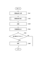
- FIG. 4 is a sequence diagram showing an evaluation method performed by the evaluation system shown in FIG.
- FIG. 5 is a flowchart showing in detail the correction process shown in FIG. 6A to 6F are diagrams showing examples of markers.
- FIG. 7 is a diagram for explaining distortion correction.
- FIGS. 8A and 8B are diagrams for explaining the extraction of the evaluation area.
- FIGS. 9A and 9B are diagrams for explaining color correction.
- FIG. 10 is a diagram illustrating an example of a neural network.
- FIG. 11 is a diagram illustrating an example of the evaluation result.
- FIG. 14 is a configuration diagram schematically showing an evaluation system including an evaluation apparatus according to the second embodiment.
- FIG. 15 is a sequence diagram showing an evaluation method performed by the evaluation system shown in FIG.
- FIG. 16 is a configuration diagram schematically showing an evaluation system including an evaluation apparatus according to the third embodiment.
- FIG. 17 is a flowchart showing an evaluation method performed by the evaluation system shown in FIG. (A) to (d) of FIG. 18 are diagrams showing modifications of the marker.
- FIG. 19 is a diagram for describing a modification of the evaluation region extraction method.
- FIG. 20 is a diagram for explaining a modification of the evaluation region extraction method.
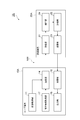
- FIG. 1 is a configuration diagram schematically showing an evaluation system including an evaluation apparatus according to the first embodiment.
- An evaluation system 1 shown in FIG. 1 is a system for evaluating the coverage of an evaluation object. Examples of the evaluation object include an almen strip, a gear, and a spring. Coverage is the ratio of the area where dents are generated by shots to the total surface area to be measured.
- the evaluation system 1 includes one or a plurality of user terminals 10 and an evaluation device 20.
- the user terminal 10 and the evaluation device 20 are connected to be communicable with each other via a network NW.
- the network NW may be configured by either wired or wireless. Examples of the network NW include the Internet, a mobile communication network, and a WAN (Wide Area Network).
- the user terminal 10 is a terminal device used by a user.
- the user terminal 10 captures the evaluation object to generate a captured image of the evaluation object, and transmits the captured image to the evaluation device 20.
- the user terminal 10 receives the evaluation result from the evaluation device 20 and outputs the evaluation result to the user.
- the user terminal 10 may be applied to a portable terminal that incorporates an imaging device, or may be applied to a device that can communicate with the imaging device. In the present embodiment, the user terminal 10 will be described using a portable terminal incorporating an imaging device. Examples of portable terminals include smartphones, tablet terminals, and notebook PCs (Personal Computers).
- FIG. 2 is a hardware configuration diagram of the user terminal shown in FIG.
- the user terminal 10 physically includes one or more processors 101, a main storage device 102, an auxiliary storage device 103, a communication device 104, an input device 105, an output device 106, and an imaging device. It can be configured as a computer having hardware such as 107.
- the processor 101 a processor having a high processing speed is used. Examples of the processor 101 include a GPU (Graphics Processing Unit) and a CPU (Central Processing Unit).
- the main storage device 102 includes a RAM (Random Access Memory) and a ROM (Read Only Memory). Examples of the auxiliary storage device 103 include a semiconductor memory and a hard disk device.
- the communication device 104 is a device that transmits and receives data to and from other devices via the network NW.
- An example of the communication device 104 is a network card. Encryption may be used for data transmission / reception via the network NW. That is, the communication device 104 may encrypt the data and transmit the encrypted data to another device. The communication device 104 may receive the encrypted data from another device and decrypt the encrypted data.
- a common key cryptosystem such as Triple DES (Data Encryption Standard) and Rijndael, or a public key cryptosystem such as RSA and ElGamal may be used.
- the input device 105 is a device used when the user operates the user terminal 10. Examples of the input device 105 include a touch panel, a keyboard, and a mouse.
- the output device 106 is a device that outputs various types of information to the user of the user terminal 10. Examples of the output device 106 include a display, a speaker, and a vibrator.
- the imaging device 107 is a device for imaging (imaging).
- the imaging device 107 is, for example, a camera module.
- the imaging apparatus 107 receives a plurality of optical system components such as a lens and an imaging element, a plurality of control system circuits that drive and control them, and an electrical signal that represents a captured image generated by the imaging element. And a circuit portion of a signal processing system for converting into an image signal which is a digital signal.
- Each function illustrated in FIG. 1 of the user terminal 10 is performed by causing each hardware device such as the main storage device 102 to read one or more predetermined computer programs under the control of one or more processors 101. This is realized by operating the hardware and reading and writing data in the main storage device 102 and the auxiliary storage device 103.
- the user terminal 10 includes an image acquisition unit 11, a correction unit 13, a transmission unit 14, a reception unit 15, an output unit 16, and a correction information acquisition unit 17.
- the image acquisition unit 11 is a part for acquiring a captured image including an evaluation object.
- the image acquisition unit 11 is realized by the imaging device 107, for example.
- the captured image may be a still image or a moving image.
- the captured image is acquired as, for example, image data indicating the pixel value of each pixel (pixel), but is expressed as a captured image for convenience of explanation.
- the image acquisition unit 11 receives, for example, a captured image captured by another device (for example, a terminal having a camera function) from the other device. To get.
- a portion that performs a captured image reception process (such as the communication device 104 in FIG. 2) functions as the image acquisition unit 11.
- the image acquisition unit 11 outputs the captured image to the correction unit 13.
- the correction unit 13 is a part for generating an evaluation image by correcting the captured image.
- the correction unit 13 extracts an evaluation area from the captured image, and generates an evaluation image based on the evaluation area.
- the evaluation area is determined according to the size of the dent area that is an image of the dent included in the captured image. For example, the correction unit 13 performs size correction, distortion correction, color correction, specular reflection removal, noise removal, and blur correction on the captured image. Details of each correction process will be described later.
- the correction unit 13 outputs the evaluation image to the transmission unit 14.
- the transmission unit 14 is a part for transmitting the evaluation image to the evaluation device 20.
- the transmission unit 14 transmits the evaluation image to the evaluation device 20 via the network NW.
- the transmission unit 14 further transmits the correction information acquired by the correction information acquisition unit 17 to the evaluation device 20.
- the transmission unit 14 is realized by the communication device 104, for example.
- the receiving unit 15 is a part for receiving an evaluation result from the evaluation device 20.
- the receiving unit 15 receives the evaluation result from the evaluation device 20 via the network NW.
- the receiving unit 15 is realized by the communication device 104, for example.
- the output unit 16 is a part for outputting the evaluation result.
- the output unit 16 is realized by the output device 106, for example.
- the output unit 16 transmits the evaluation result to the other device via the network NW, for example.
- a part (such as the communication device 104 in FIG. 2) that performs the evaluation result transmission process functions as the output unit 16.
- the correction information acquisition unit 17 is a part for acquiring correction information of the evaluation result. For example, the user may correct the evaluation result using the input device 105 after confirming the evaluation result output by the output unit 16. At this time, the correction information acquisition unit 17 acquires the corrected evaluation result as correction information. The correction information acquisition unit 17 outputs the correction information to the transmission unit 14.
- the evaluation device 20 is a device that evaluates the coverage of the evaluation object using a captured image (evaluation image) of the evaluation object.
- the evaluation device 20 is configured by an information processing device (server device) such as a computer, for example.
- FIG. 3 is a hardware configuration diagram of the evaluation apparatus shown in FIG.
- the evaluation device 20 may be physically configured as a computer including hardware such as one or more processors 201, a main storage device 202, an auxiliary storage device 203, and a communication device 204.
- the processor 201 a processor having a high processing speed is used. Examples of the processor 201 include a GPU and a CPU.
- the main storage device 202 includes a RAM, a ROM, and the like. Examples of the auxiliary storage device 203 include a semiconductor memory and a hard disk device.
- the communication device 204 is a device that transmits and receives data to and from other devices via the network NW.
- An example of the communication device 204 is a network card. Encryption may be used for data transmission / reception via the network NW. In other words, the communication device 204 may encrypt the data and transmit the encrypted data to another device. The communication device 204 may receive the encrypted data from another device and decrypt the encrypted data.
- a common key cryptosystem such as Triple DES and Rijndael
- a public key cryptosystem such as RSA and ElGamal
- the communication device 204 may perform user authentication for determining whether the user of the user terminal 10 is a regular user or a non-regular user.
- the evaluation device 20 may evaluate the coverage when the user is a regular user, and may not evaluate the coverage when the user is a non-regular user.
- a user ID identifier
- a one-time pad one-time password
- Each function shown in FIG. 1 of the evaluation device 20 is performed by causing each hardware item such as the main storage device 202 to read one or more predetermined computer programs under the control of one or more processors 201. This is realized by operating the hardware and reading and writing data in the main storage device 202 and the auxiliary storage device 203.
- the evaluation device 20 includes a reception unit 21, an evaluation unit 22, and a transmission unit 23.
- the receiving unit 21 is a part for receiving an evaluation image from the user terminal 10.
- the receiving unit 21 receives an evaluation image from the user terminal 10 via the network NW.
- the receiving unit 21 further receives correction information from the user terminal 10.
- the receiving unit 21 is realized by the communication device 204, for example.
- the receiving unit 21 outputs the evaluation image and the correction information to the evaluation unit 22.
- the evaluation unit 22 is a part for evaluating the coverage of the evaluation object based on the evaluation image.
- the evaluation unit 22 evaluates the coverage of the evaluation object using a neural network.
- the neural network may be a convolutional neural network (CNN) or a recurrent neural network (RNN).
- the evaluation unit 22 outputs the evaluation result to the transmission unit 23.
- the transmission unit 23 is a part for transmitting the evaluation result to the user terminal 10.
- the transmission unit 23 transmits the evaluation result to the user terminal 10 via the network NW.
- the transmission unit 23 is realized by the communication device 204, for example. Since the transmission unit 23 outputs (transmits) the evaluation result to the user terminal 10, it can be regarded as an output unit.
- FIG. 4 is a sequence diagram showing an evaluation method performed by the evaluation system shown in FIG.
- FIG. 5 is a flowchart showing in detail the correction process shown in FIG. 6A to 6F are diagrams showing examples of markers.
- FIG. 7 is a diagram for explaining distortion correction.
- FIGS. 8A and 8B are diagrams for explaining the extraction of the evaluation area.
- FIGS. 9A and 9B are diagrams for explaining color correction.
- FIG. 10 is a diagram illustrating an example of a neural network.
- FIG. 11 is a diagram illustrating an example of the evaluation result.
- (A) and (b) of FIG. 12 is a figure which shows the example of a display of an evaluation result.
- (A) and (b) of FIG. 13 is a figure which shows the example of correction of an evaluation result.
- the series of processes of the evaluation method illustrated in FIG. 4 is started, for example, when the user of the user terminal 10 photographs the evaluation object using the imaging device 107.
- the image acquisition unit 11 acquires a captured image of the evaluation object (step S01).
- the image acquisition unit 11 acquires an image of the evaluation object generated by the imaging device 107 as a captured image.
- the image acquisition unit 11 outputs the acquired captured image to the correction unit 13.
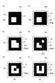
- the marker MK may be attached to the evaluation object before acquiring the captured image of the evaluation object.
- the marker MK is used for correcting a captured image in image processing described later.
- the marker MK has a shape that can specify the direction of the marker MK.
- the marker MK is asymmetric in at least one of the vertical direction and the width direction. Specifically, as shown in FIGS. 6A to 6F, the marker MK includes a white area Rw and a black area Rb. In order to facilitate image processing to be described later, the marker MK has a square edge F1.
- the edge F1 is an edge of the region Rb.
- the marker MK may be surrounded by a frame F2, and a gap Rgap may be provided between the frame F2 and the region Rb.
- the marker MK is drawn on the sheet-like member.
- the user of the user terminal 10 directly attaches the sheet-like member including the marker MK to the evaluation object.
- the user may attach a sheet-like member including the marker MK to the evaluation object using a UAV (Unmanned Aero Vehicle) or an expansion / contraction rod.
- UAV Unmanned Aero Vehicle
- the marker MK only needs to be composed of two or more regions with different colors.
- the color assigned to the region Rw may not be white, but may be gray or the like.
- the color assigned to the region Rb may not be black, but may be a color having saturation.
- the correction unit 13 corrects the captured image (step S02).
- the correction unit 13 performs distortion correction in order to correct distortion of the captured image (step S21).
- the captured image may be distorted as compared to an image obtained by photographing the evaluation object from the front.
- the correction unit 13 performs distortion correction by converting the captured image into an image obtained by photographing the evaluation object from the front based on the distance between the imaging device 107 and each position of the evaluation object.
- the correction unit 13 may further perform an aspect correction as a distortion correction.
- the correction unit 13 may perform distortion correction using the marker MK.
- the captured image of the evaluation object to which the marker MK is attached includes a marker region Rm that is an image (image region) of the marker MK.
- the correction unit 13 first extracts the marker region Rm from the captured image.
- the correcting unit 13 extracts the marker region Rm by performing object detection processing or edge detection processing on the captured image, for example.
- edge detection processing may be used because edge detection processing has higher detection accuracy and processing speed than object detection processing.
- the correction unit 13 confirms whether or not the extracted marker region Rm is an image of the marker MK. For example, the correction unit 13 performs binarization processing on the marker region Rm after performing histogram averaging processing on the marker region Rm. Then, the correction unit 13 compares the binarized marker region Rm and the marker MK, and determines that the marker region Rm is an image of the marker MK when the two match. Thereby, the vertex coordinates of the marker MK in the captured image are acquired. The correction unit 13 determines that the marker region Rm is not an image of the marker MK when the two do not match, and extracts the marker region Rm again.
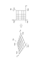
- the correction unit 13 calculates the direction of the marker MK in the captured image using the marker region Rm. Since the marker MK is asymmetric in at least one of the vertical direction and the width direction, the direction of the marker MK in the captured image can be calculated. Then, as illustrated in FIG. 7, the correction unit 13 performs projective transformation on the captured image so that the original shape of the marker MK is restored from the vertex coordinates and orientation of the marker MK in the captured image, thereby evaluating the correction.
- the captured image is converted into an image obtained by photographing the object from the front.
- the correcting unit 13 sets the vertex Pm1 as the origin, the direction from the vertex Pm1 to the vertex Pm2 as the X1 axis direction, and the direction from the vertex Pm1 toward the vertex Pm4 as the Y1 axis direction. Then, the correction unit 13 restores the shape of the marker MK by converting the X1-Y1 coordinate system to the XY orthogonal coordinate system. Thereby, distortion correction is performed.
- the correction unit 13 extracts the evaluation area Re from the captured image (step S22). Since one shot peening is performed with the same size of the projection material, the size of the dent is the same.
- the types of projection materials used for shot peening include, for example, projection materials having a diameter (particle size) of about 0.1 mm to 1 mm. For this reason, the size of the projection material used in one shot peening may differ from the size of the projection material used in another shot peening.
- the influence of one dent on the evaluation of the coverage differs depending on the size (diameter) of the projection material. Therefore, as illustrated in FIGS.
- the correction unit 13 extracts the evaluation region Re from the captured image G based on the size of the dent region De included in the captured image G. Then, an evaluation image is generated based on the evaluation region Re.
- the dent region De is an image of a dent generated on the evaluation object.
- an average size (for example, an average diameter) of a plurality of dent areas De included in the captured image G is used.
- the correction unit 13 detects a plurality of dent regions De included in the captured image G by object detection. Then, the correction unit 13 calculates an average size (for example, an average diameter) of the plurality of dent areas De included in the captured image G, and the evaluation area Re becomes larger as the average size of the dent area De is larger. Then, the evaluation area Re is extracted from the captured image G.
- the correcting unit 13 sets the size of the evaluation region Re by multiplying the average size (average diameter) of the dent region De by a predetermined magnification (for example, 5 to 10 times). . For example, the correction unit 13 extracts a square area having a length of one side as a multiplication result as an evaluation area Re from the captured image.
- the correction unit 13 corrects the size of the evaluation area Re (step S23).
- the size of the evaluation region Re can be changed according to the size of the dent region De.
- the correction unit 13 performs an expansion / contraction process of the evaluation region Re so that the size of the dent region De is matched with a predetermined size (reference particle size).
- the size of the evaluation area Re is adjusted to a predetermined evaluation size.
- the evaluation size is the size of a reference image (teacher data) used for learning of the neural network NN.
- the correction unit 13 compares the size (average diameter) of the dent region De with the reference particle size, and determines whether to perform the enlargement process or the reduction process.
- the correction unit 13 performs an enlargement process when the average diameter of the dent area De is smaller than the reference particle diameter, and performs a reduction process when the average diameter of the dent area De is larger than the reference particle diameter. . That is, the correction unit 13 enlarges or reduces the evaluation area Re to adjust the size of the evaluation image to the evaluation size.
- a bilinear interpolation method is used for example.
- an average pixel method is used for example.
- Other enlargement / reduction algorithms may be used for the enlargement process and the reduction process, but it is desirable that the image state be maintained even when the extension / reduction process is performed.
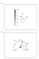
- the correction unit 13 performs color correction of the evaluation area Re (step S24). Even for the same evaluation object, the brightness of the image may change depending on the shooting environment. Further, when the color of the light source used for photographing is different, the color of the image may be different. Color correction is performed to reduce the influence of the shooting environment.
- the correcting unit 13 corrects the color of the evaluation area Re based on the color of the reference area included in the captured image.
- the reference area is an image (image area) of a reference body with a specific color.
- the region Rw of the marker MK can be used as the reference body.
- the color of the region Rw of the marker MK is measured in advance with a color meter or the like, and a reference value indicating the measured color is stored in a memory (not shown).
- a value indicating a color an RGB value, an HSV value, or the like is used.
- the correction unit 13 acquires the color value of the region Rw in the marker region Rm included in the captured image (evaluation region Re), and compares the acquired value with a reference value. Then, color correction is performed so that these differences are small (for example, zero).
- gamma correction or the like is used.
- a difference may be added to each pixel value (offset processing).
- the marker MK may not be used as the reference body. In this case, even if color correction of the evaluation region Re is performed in the same manner as in the case of using the marker MK, a sample (for example, a gray board) whose color is measured in advance is used as a reference body and photographed together with the evaluation object. Good.
- the correction unit 13 may perform color correction based on the gray hypothesis.
- the correction unit 13 removes the specular reflection from the evaluation region Re (step S25).
- Specular reflection may be caused when the evaluation object has a metallic luster. Depending on the state of the coating film of the evaluation object, specular reflection may be caused. In the image, the part that caused the specular reflection usually appears as strong white. That is, the portion where the specular reflection occurs causes whiteout in the image.
- the specular reflection portion can be detected as a white portion, so the correction unit 13 removes the specular reflection using the color corrected image (evaluation region Re).
- the correction unit 13 specifies the specular reflection part based on the pixel value of each pixel included in the evaluation region Re. For example, the correction unit 13 determines that the pixel is a part of the specular reflection portion when all of the RGB pixel values are larger than a predetermined threshold value.
- the correction unit 13 converts the pixel value into HSV, and specifies the specular reflection part by performing the same threshold processing on brightness (V) or both brightness (V) and saturation (S). May be.
- the correction unit 13 removes the specular reflection from the specular reflection portion and restores the original image information (pixel value).
- the correction unit 13 automatically interpolates (restores) the image information of the specular reflection portion with the image information in the vicinity of the specular reflection portion by, for example, a method using Navier-Stokes or a fast marching method of Alexander Telea.
- the correction unit 13 may restore the image information of the specular reflection part by learning in advance images having various coverage values by machine learning. For machine learning, for example, GAN (Generative Adversarial Network) is used. Note that the correction unit 13 may restore the image information for a region in which the outer edge of the specular reflection portion is expanded (that is, a region that includes the specular reflection portion and is larger than the specular reflection portion).
- the correction unit 13 removes noise from the evaluation region Re (step S26).
- the correction unit 13 removes noise from the evaluation region Re using, for example, a denoising filter (denoising function) such as a Gaussian filter and a low-pass filter.
- a denoising filter denoising function
- the correction unit 13 performs blur correction on the evaluation area Re (step S27).
- blurring such as camera shake may occur.
- the correction unit 13 performs image blur correction using, for example, a Wiener filter and a blind deconvolution algorithm.
- the correction process in FIG. 5 is an example, and the correction process performed by the correction unit 13 is not limited to this. Some or all of steps S21 and S23 to S27 may be omitted. Steps S21 to S27 may be performed in any order. As described above, when the specular reflection removal is performed after the color correction, the specular reflection portion appears as strong white in the image, so that the specular reflection portion specifying accuracy is improved.
- the correction unit 13 considers that the marker region Rm is configured by a plurality of blocks arranged in a grid, and uses the coordinates of the four vertices of the marker region Rm (marker MK). Thus, the vertex coordinates of each block may be obtained. Thereby, the correction
- the correction unit 13 outputs the captured image corrected by the correction process in step S02 to the transmission unit 14 as an evaluation image, and the transmission unit 14 transmits the evaluation image to the evaluation device 20 via the network NW.
- the transmission unit 14 transmits the evaluation image to the evaluation device 20 together with a terminal ID that can uniquely identify the user terminal 10. For example, an IP (Internet Protocol) address may be used as the terminal ID.
- the reception unit 21 receives the evaluation image transmitted from the user terminal 10 and outputs the evaluation image to the evaluation unit 22.
- the correction unit 13 may not output the evaluation image to the transmission unit 14 when the evaluation image is not clear.
- the transmission unit 14 may encrypt the evaluation image and transmit the encrypted evaluation image to the evaluation device 20. In this case, the receiving unit 21 receives the encrypted evaluation image from the user terminal 10, decrypts the encrypted evaluation image, and outputs the evaluation image to the evaluation unit 22.
- the evaluation unit 22 evaluates the coverage of the evaluation object based on the evaluation image (step S04).
- the evaluation unit 22 evaluates the coverage of the evaluation object using the neural network NN shown in FIG.
- the evaluation unit 22 assigns an image ID that can uniquely identify the evaluation image to the evaluation image.
- Neural network NN inputs an image for evaluation and outputs the matching rate of each category.
- a value obtained by collecting coverage in a predetermined ratio unit can be used. For example, when the coverage is expressed as a percentage, categories from 0 to 98% are set in units of 10%.
- JIS B2711, and SAE J2277 are mentioned as a standard regarding coverage.
- the upper limit value at which the coverage can be measured is 98% (full coverage).
- the category is not limited to the unit of 10%, and may be set in units of 5% or may be set in units of 1%.
- the category a value obtained by collecting the coverage from 0 to 98% in units of 10% is used.
- the category “100%” is used for convenience of explanation.
- the relevance ratio represents the probability that the coverage of the evaluation object belongs to the category. The higher the matching rate, the higher the possibility that the coverage of the evaluation object belongs to the category.
- the evaluation unit 22 may separate the evaluation image into one or a plurality of channels and use the image information (pixel value) of each channel as an input to the neural network NN. For example, the evaluation unit 22 separates the evaluation image into each component of the color space. When the RGB color space is used as the color space, the evaluation unit 22 separates the evaluation image into an R component pixel value, a G component pixel value, and a B component pixel value. When the HSV color space is used as the color space, the evaluation unit 22 separates the evaluation image into an H component pixel value, an S component pixel value, and a V component pixel value. The evaluation unit 22 may convert the evaluation image into a gray scale and use the converted image as an input to the neural network NN.
- the neural network NN has an input layer L1, an intermediate layer L2, and an output layer L3.
- the input layer L1 is located at the entrance of the neural network NN, and M input values x i (i is an integer from 1 to M) are input to the input layer L1.
- the input layer L1 includes a plurality of neurons 41.
- the neurons 41 are provided corresponding to the input values x i , and the number of neurons 41 is equal to the total number M of the input values x i . That is, the number of neurons 41 is equal to the total number of pixels included in each channel of the evaluation image.
- the i-th neuron 41 outputs the input value x i to each neuron 421 of the first intermediate layer L21 of the intermediate layer L2.
- the input layer L1 includes a node 41b.
- the node 41b outputs a bias value b j (j is an integer from 1 to M1) to each neuron 421.
- the intermediate layer L2 is located between the input layer L1 and the output layer L3.
- the intermediate layer L2 is also called a hidden layer because it is hidden from the outside of the neural network NN.
- the intermediate layer L2 includes one or more layers.
- the intermediate layer L2 includes a first intermediate layer L21 and a second intermediate layer L22.
- the first intermediate layer L21 has M1 neurons 421.
- the j-th neuron 421 adds a bias value b j to the sum of values obtained by weighting each input value x i by the weighting coefficient w ij to obtain a calculated value.
- z j is obtained.
- the neuron 421 sequentially performs, for example, convolution, calculation using an activation function, and pooling. In this case, for example, a ReLU function is used as the activation function.
- the j-th neuron 421 outputs the calculated value z j to each neuron 422 of the second intermediate layer L22.
- the first intermediate layer L21 includes a node 421b.
- the node 421b outputs a bias value to each neuron 422.
- each neuron performs the same calculation as that of the neuron 421 and outputs the calculated value to each neuron in the subsequent layer.
- the final-stage neuron (here, the neuron 422) of the intermediate layer L2 outputs the calculated value to each neuron 43 of the output layer L3.
- the output layer L3 is located at the exit of the neural network NN and outputs an output value y k (k is an integer from 1 to N).
- the output value y k is assigned to each category, and is a value corresponding to the matching rate of that category.
- the output layer L3 includes a plurality of neurons 43.
- the neurons 43 are provided corresponding to the output values y k , and the number of neurons 43 is equal to the total number N of output values y k . That is, the number of neurons 43 is equal to the number of categories indicating coverage.
- Each neuron 43 performs a calculation similar to that of the neuron 421 and calculates an activation function using the calculation result as an argument to obtain an output value y k .
- Examples of the activation function include a softmax function, a ReLU function, a hyperbolic function, a sigmoid function, an identity function, and a step function.
- a softmax function is used. For this reason, each output value y k is normalized so that the sum of the N output values y k is 1. That is, the precision (%) is obtained by multiplying the output value y k by 100.
- the evaluation unit 22 outputs the N output values y k together with the image ID of the evaluation image to the transmission unit 23 as the evaluation result of the evaluation image.
- An array of N output values y k is determined in advance, and each output value y k is associated with one of the N categories.
- the evaluation unit 22 may use the largest output value among the N output values y k as an evaluation result together with the category name or index (corresponding to “number” shown in FIG. 11) corresponding to the output value. .
- an array of output values corresponding to the precision shown in FIG. 11 is output to the transmitting unit 23 as an evaluation result.
- the user terminal 10 can determine how to output to the user.
- the transmission part 23 transmits an evaluation result to the user terminal 10 via the network NW (step S05).
- the transmission unit 23 identifies the destination user terminal 10 based on the terminal ID transmitted from the user terminal 10 together with the evaluation image, and transmits the evaluation result to the user terminal 10.
- the reception unit 15 receives the evaluation result transmitted from the evaluation device 20 and outputs the evaluation result to the output unit 16.
- the transmitting unit 23 may encrypt the evaluation result and transmit the encrypted evaluation result to the user terminal 10 as described above. In this case, the receiving unit 15 receives the encrypted evaluation result from the evaluation device 20, decrypts the encrypted evaluation result, and outputs the evaluation result to the output unit 16.
- the output unit 16 generates output information for notifying the user of the evaluation result, and outputs the evaluation result to the user based on the output information (step S06).
- the output unit 16 displays, for example, the category name (coverage 00%) having the highest relevance rate and the relevance rate.
- the output unit 16 may display the coverage evaluation result on the graph using the arrow Pa.
- the output unit 16 may display the evaluation result as text. For example, the output unit 16 displays “Result: Coverage 45%” or the like.
- the output unit 16 may display all the category names and their relevance ratios as text.
- the output unit 16 may notify the user whether the shot peening process is acceptable or unacceptable using the evaluation result.
- the output unit 16 may output the evaluation result by voice or may output the evaluation result by vibration.
- the form of output by the output unit 16 may be set by the user.
- the correction information acquisition unit 17 determines whether or not an evaluation result correction operation has been performed by the user. For example, after confirming the evaluation result output by the output unit 16, the user operates the input device 105 to display a screen for correcting the evaluation result.
- the user operates the input device 105 and moves the arrow Pa using the pointer MP, thereby specifying the coverage on the graph. That is, the user moves the arrow Pa so that the coverage is determined by visually inspecting the evaluation object, and the numerical value corresponding to the coverage determined by the user is indicated.
- a text box may be used for the user to specify the coverage.
- Objects such as radio buttons, drop-down lists, or sliders may be used for the user to select a category.
- the correction information acquisition unit 17 determines that the correction operation has not been performed, a series of processes of the evaluation method by the evaluation system 1 ends. On the other hand, when the correction information acquisition unit 17 determines that the correction operation has been performed by the input device 105, the correction information acquisition unit 17 acquires information indicating the corrected category as correction information together with the image ID of the evaluation image on which the correction operation has been performed. (Step S07).
- the correction information acquisition unit 17 outputs the correction information to the transmission unit 14, and the transmission unit 14 transmits the correction information to the evaluation device 20 via the network NW (Step S08).
- the receiving unit 21 receives the correction information transmitted from the user terminal 10 and outputs the correction information to the evaluation unit 22.
- the transmission unit 14 may encrypt the correction information and transmit the encrypted correction information to the evaluation device 20.
- the reception unit 21 receives the encrypted correction information from the user terminal 10, decrypts the encrypted correction information, and outputs the correction information to the evaluation unit 22.
- the evaluation unit 22 performs learning based on the correction information (step S09). Specifically, the evaluation unit 22 uses a set of the corrected category and the evaluation image as teacher data.
- the evaluation unit 22 may learn the neural network NN by any of online learning, mini-batch learning, and batch learning. Online learning is a method in which learning is performed using new teacher data each time new teacher data is acquired. Mini-batch learning is a method in which a certain amount of teacher data is taken as one unit and learning is performed using one unit of teacher data. Batch learning is a method of performing learning using all teacher data. For the learning, an algorithm such as back propagation is used. Note that learning of the neural network NN means updating the weighting coefficient and bias value used in the neural network NN to more optimal values.
- each function part in the user terminal 10 and the evaluation apparatus 20 is implement
- the evaluation program including these program modules is provided by a computer-readable recording medium such as a ROM or a semiconductor memory.
- the evaluation program may be provided as a data signal via a network.
- the evaluation area Re is extracted from the captured image of the evaluation object, and an evaluation image is generated based on the evaluation area Re. Then, the coverage is evaluated based on the evaluation image, and the evaluation result is output.
- the evaluation area Re is extracted from the captured image based on the size of the dent area De which is an image of the dent generated on the evaluation object.
- the evaluation region Re is extracted from the captured image so that the evaluation region Re (the area thereof) increases as the dent region De increases.
- the size of the evaluation region Re is set by multiplying the size (for example, average diameter) of the dent region De by a predetermined constant. For this reason, since the range (area) of the evaluation region Re can be sufficiently increased with respect to the size of the dent region De, the influence of one dent on the coverage can be reduced. As a result, it is possible to improve the evaluation accuracy of the coverage.
- the evaluation area Re is enlarged or reduced so that the size of the dent area De is adjusted to a predetermined size (for example, a reference particle diameter). For this reason, evaluation by the neural network NN can be performed appropriately. Moreover, since the coverage can be evaluated based on a common standard for the projection materials having different particle diameters, it is possible to improve the evaluation accuracy of the coverage.
- the color tone of the captured image may change depending on the color tone of the light source used for shooting.
- the brightness of the captured image may vary depending on the amount of light irradiation.
- the color of the evaluation region Re is corrected based on the color of the reference region (for example, the region Rw in the marker region Rm) included in the captured image.
- the color of the evaluation region Re is corrected so that the color of the region Rw in the marker region Rm becomes the color of the region Rw in the marker MK. Thereby, the influence of light can be reduced. As a result, the coverage evaluation accuracy can be further improved.
- Coverage is evaluated using the neural network NN.
- the pattern generated on the surface of the evaluation object by the shot peening process is indefinite. For this reason, in general object detection, it is difficult to specify the position and state of an irregular object. Pattern recognition is not suitable for recognizing a myriad of patterns.
- the coverage can be evaluated, and the accuracy of the coverage evaluation can be further improved.
- FIG. 14 is a configuration diagram schematically showing an evaluation system including an evaluation apparatus according to the second embodiment.
- An evaluation system 1A shown in FIG. 14 is mainly different from the evaluation system 1 in that a user terminal 10A is provided instead of the user terminal 10 and an evaluation device 20A is provided instead of the evaluation device 20.
- the user terminal 10A is mainly different from the user terminal 10 in that the correction unit 13 is not provided and a captured image is transmitted to the evaluation device 20A instead of the evaluation image.
- the image acquisition unit 11 outputs the captured image to the transmission unit 14.
- the transmission unit 14 transmits the captured image to the evaluation device 20A.
- Evaluation device 20A is mainly different from evaluation device 20 in that a captured image is received from user terminal 10A instead of an image for evaluation, and correction unit 24 is further provided.
- the receiving unit 21 receives the captured image from the user terminal 10 ⁇ / b> A and outputs the captured image to the correction unit 24.
- the correction unit 24 has the same function as the correction unit 13. That is, the correction unit 24 extracts an evaluation area from the captured image, and generates an evaluation image based on the evaluation area. Then, the correction unit 24 outputs the evaluation image to the evaluation unit 22.
- FIG. 15 is a sequence diagram showing an evaluation method performed by the evaluation system shown in FIG.
- the image acquisition unit 11 acquires a captured image of the evaluation object (step S31). For example, as in step S01, the image acquisition unit 11 acquires an image of the evaluation target generated by the imaging device 107 as a captured image.
- the image acquisition unit 11 outputs the acquired captured image to the transmission unit 14, and the transmission unit 14 transmits the captured image to the evaluation device 20A via the network NW (step S32).
- the transmission unit 14 transmits the captured image to the evaluation apparatus 20A together with a terminal ID that can uniquely identify the user terminal 10A.
- the reception unit 21 receives the captured image transmitted from the user terminal 10 ⁇ / b> A and outputs the captured image to the correction unit 24.
- the transmission unit 14 may encrypt the captured image and transmit the encrypted captured image to the evaluation device 20A.
- the reception unit 21 receives the encrypted captured image from the user terminal 10 ⁇ / b> A, decrypts the encrypted captured image, and outputs the captured image to the correction unit 24.
- the correction unit 24 corrects the captured image (step S33). Since the process of step S33 is the same as the process of step S02, the detailed description thereof is omitted.
- the correction unit 24 outputs the captured image corrected by the correction process in step S33 to the evaluation unit 22 as an evaluation image. Thereafter, the processing from step S34 to step S39 is the same as the processing from step S04 to step S09, and therefore detailed description thereof is omitted. As described above, a series of processes of the evaluation method by the evaluation system 1A is completed.
- each functional unit in the user terminal 10A and the evaluation device 20A is realized by executing a program module for realizing each function in a computer constituting the user terminal 10A and the evaluation device 20A.
- the evaluation program including these program modules is provided by a computer-readable recording medium such as a ROM or a semiconductor memory.
- the evaluation program may be provided as a data signal via a network.
- the evaluation device 20A, the evaluation method, the evaluation program, and the recording medium according to the second embodiment the evaluation system 1, the evaluation device 20, the evaluation method, the evaluation program, and the recording medium according to the first embodiment Similar effects are produced. Further, in the evaluation system 1A, the evaluation device 20A, the evaluation method, the evaluation program, and the recording medium according to the second embodiment, the user terminal 10A does not have the correction unit 13, and therefore the processing load on the user terminal 10A can be reduced. it can.
- FIG. 16 is a configuration diagram schematically showing an evaluation system including an evaluation apparatus according to the third embodiment.
- the evaluation system 1B shown in FIG. 16 is mainly different from the evaluation system 1 in that the user terminal 10B is provided in place of the user terminal 10 and the evaluation device 20 is not provided.
- the user terminal 10B is mainly different from the user terminal 10 in that the evaluation unit 18 is further provided, and the transmission unit 14 and the reception unit 15 are not provided. In this case, the user terminal 10B is also a stand-alone evaluation device.
- the correction unit 13 outputs an evaluation image to the evaluation unit 18.
- the correction information acquisition unit 17 outputs the correction information to the evaluation unit 18.
- the evaluation unit 18 has the same function as the evaluation unit 22. That is, the evaluation unit 18 evaluates the coverage of the evaluation object based on the evaluation image. Then, the evaluation unit 18 outputs the evaluation result to the output unit 16.
- FIG. 17 is a flowchart showing an evaluation method performed by the evaluation system shown in FIG.
- the image acquisition unit 11 acquires a captured image of the evaluation object as in step S01 (step S41). Then, the image acquisition unit 11 outputs the captured image to the correction unit 13. Subsequently, the correction unit 13 corrects the captured image (step S42). Since the process of step S42 is the same as the process of step S02, the detailed description thereof is omitted. Then, the correction unit 13 outputs the captured image corrected by the correction process in step S42 to the evaluation unit 18 as an evaluation image.
- the evaluation unit 18 evaluates the coverage of the evaluation object based on the evaluation image (step S43). Since the process of step S43 is the same as the process of step S04, its detailed description is omitted. Then, the evaluation unit 18 outputs the evaluation result to the output unit 16. Subsequently, the output unit 16 generates output information for notifying the user of the evaluation result, and outputs the evaluation result to the user based on the output information (step S44). Since the process of step S44 is the same as the process of step S06, its detailed description is omitted.
- the correction information acquisition unit 17 determines whether or not an evaluation result correction operation has been performed by the user (step S45).
- step S45: NO the series of processes of the evaluation method by the evaluation system 1B ends.
- step S45: YES the correction information acquisition unit 17 displays the information indicating the corrected category together with the image ID of the evaluation image on which the correction operation has been performed. Get as. Then, the correction information acquisition unit 17 outputs the correction information to the evaluation unit 18.
- step S46 the evaluation unit 18 performs learning based on the correction information. Since the process of step S46 is the same as the process of step S09, detailed description thereof is omitted. As described above, a series of processes of the evaluation method by the evaluation system 1B is completed.
- each functional unit in the user terminal 10B is realized by executing a program module for realizing each function in a computer constituting the user terminal 10B.
- the evaluation program including these program modules is provided by a computer-readable recording medium such as a ROM or a semiconductor memory.
- the evaluation program may be provided as a data signal via a network.
- the evaluation system 1B the user terminal 10B, the evaluation method, the evaluation program, and the recording medium according to the third embodiment
- the user terminal 10B, the evaluation method, the evaluation program, and the recording medium according to the third embodiment it is not necessary to transmit / receive data via the network NW, and therefore, accompanying the communication via the network NW. There is no time lag, and the response speed can be improved. Further, it becomes possible to reduce traffic and communication charges of the network NW.
- evaluation system the evaluation device, the evaluation method, the evaluation program, and the recording medium according to the present disclosure are not limited to the above embodiment.
- the user terminals 10, 10 ⁇ / b> A, and 10 ⁇ / b> B may not include the correction information acquisition unit 17.
- batch normalization is a process of converting the output value of each layer so that the variance is constant. In this case, since it is not necessary to use a bias value, nodes (node 41b, node 421b, etc.) that output the bias value can be omitted.
- evaluation units 18 and 22 may evaluate the coverage based on the evaluation image using a method other than the neural network.
- the output unit 16 may output the evaluation result to a memory (storage device) (not shown) and store the evaluation result in the memory.
- the output unit 16 creates management data in which an evaluation result is associated with a management number that can uniquely identify an evaluation result, a date on which the evaluation is performed, and the evaluation result, and stores the management data.
- the shape of the marker MK is not limited to a square.
- the shape of the marker MK may be a rectangle.
- the marker MK has a shape that can specify the orientation of the marker MK, but the shape of the marker MK is not limited to a shape having directivity.
- the shape of the marker MK may be an omnidirectional shape.
- the shape of the region Rb may be a square
- the shape of the region Rw may be a square that is slightly smaller than the region Rb.
- the center point of the region Rb and the center point of the region Rw may be overlapped, and each side of the region Rb and each side of the region Rw may be arranged in parallel to each other.
- the marker MK may have an opening Hm.
- the opening Hm is a through hole that penetrates the sheet-like member on which the marker MK is drawn.
- the opening area of the opening Hm is sufficiently larger than the area of the evaluation region Re that can be extracted.
- amendment parts 13 and 24 may extract the area
- the boundary between the marker region Rm and the region to be evaluated may become unclear due to light reflection or the like.
- the edge may not be detected by the edge detection process.
- object detection if the determination threshold is too small, false detections increase, and if the determination threshold is excessively large, detection omissions increase.
- the direction (angle) of the marker region Rm cannot be obtained by object detection itself.
- the edge enhancement process is performed after the marker area Rm is extracted by the object detection process, and the edge detection process is further performed, the detection accuracy is improved, but the color of the outer edge portion of the marker area Rm and the periphery of the marker area Rm In the case where the color of the color hardly changes, detection omission may occur.
- the marker MK is surrounded by the frame F2, and between the frame F2 and the region Rb.
- a gap Rgap is provided.
- the gap Rgap surrounds the region Rb along the edge F1.
- the color of the gap Rgap is different from the color of the outer edge portion (that is, the region Rb) of the marker MK. Therefore, even if the color around the marker area Rm (outside the frame F2) is similar to the color of the outer edge portion (area Rb) of the marker area Rm, the outer edge (edge F1) of the marker area Rm is clear. Therefore, the outer edge of the marker region Rm can be detected.
- the edge enhancement process when the edge enhancement process is performed after the marker area Rm is extracted by the object detection process and the edge detection process is further performed, the vertices (vertices Pm1 to Pm4) of the area Rb can be detected more reliably. Therefore, the marker region Rm can be extracted with high speed and high accuracy. As a result, the coverage evaluation accuracy can be further improved.
- the distance between the frame F2 and the region Rb (the width of the gap Rgap) may be, for example, one tenth or more of one side of the marker MK in order to secure the gap Rgap.
- the distance between the frame F2 and the region Rb (the width of the gap Rgap) may be, for example, less than half of one side of the marker MK in consideration of ease of use of the marker MK.
- the frame F2 may not be a frame that completely surrounds the marker MK. That is, the missing part Fgap may be provided in the frame F2.
- the frame F2 is not limited to a solid line and may be a broken line. In this case, the frame F2 has a shape in which the frame line of the frame F2 is interrupted.
- the detection accuracy of the marker region Rm Will improve. That is, since the possibility that the vertex of the frame F2 is detected can be reduced, the vertex of the marker region Rm (region Rb) can be more reliably detected. As a result, the coverage evaluation accuracy can be further improved.
- the correction units 13 and 24 randomly extract the evaluation area Re from the captured image G when extracting the evaluation area Re having a size set based on the dent area De from the captured image G. And the determined evaluation region Re may be extracted.
- the correction units 13 and 24 obtain the maximum value of coordinates that can be taken by the reference point Pr of the evaluation region Re.
- the reference point Pr is one of the four vertices of the evaluation area Re, and here is the vertex closest to the origin of the XY coordinates among the four vertices of the evaluation area Re.
- the maximum value y Crop_max maximum value x Crop_max and Y coordinates of the X-coordinate of the reference point Pr is expressed by the following equation (2). Note that the vertex Pg1 of the captured image G is located at the origin (0, 0), the vertex Pg2 is located at (X g , 0), the vertex Pg3 is located at (X g , Y g ), and the vertex Pg4 is ( 0, Y g ).
- the correction units 13 and 24 randomly determine the coordinates (x crop , y crop ) of the reference point of the evaluation region Re using Expression (3).
- the function random (minimum value, maximum value) is a function that returns an arbitrary value included in the range from the minimum value to the maximum value.
- the correction units 13 and 24 may determine the coordinates of the reference point of the evaluation area Re again when the determined evaluation area Re and the marker area Rm overlap.
- the correction units 13 and 24 may specify the extraction direction for the marker region Rm and extract the evaluation region Re from the captured image G.
- the correction units 13 and 24 calculate the coordinates (x cg , y cg ) of the center position Cg of the captured image G and the coordinates (x cm , y cm ) of the center position Cm of the marker region Rm. To do.
- amendment parts 13 and 24 calculate the vector V which goes to center position Cg from center position Cm, as shown by Formula (4).
- the correction units 13 and 24 determine the position of the evaluation region Re in the direction indicated by the vector V from the marker region Rm. For example, the correction units 13 and 24 determine the position of the evaluation region Re so that the reference point Pr of the evaluation region Re is located in the direction indicated by the vector V from the center position Cm.
- the reference point Pr is the vertex closest to the marker region Rm among the four vertices of the evaluation region Re.
- the correction units 13 and 24 determine the position of the evaluation region Re so as not to overlap with the marker region Rm.
- the correction units 13 and 24 include the coordinates (x crop_max , y crop_max ) of the reference point Pr_max farthest from the marker region Rm and the reference closest to the marker region Rm among the coordinates that the reference point Pr can take.
- the coordinates (x crop_min , y crop_min ) of the point Pr_min are calculated.
- the correcting units 13 and 24 determine the position of the evaluation region Re so that the reference point Pr is positioned on the line segment between these two points.
Landscapes
- Engineering & Computer Science (AREA)
- Physics & Mathematics (AREA)
- Theoretical Computer Science (AREA)
- General Physics & Mathematics (AREA)
- Computer Vision & Pattern Recognition (AREA)
- Quality & Reliability (AREA)
- Biophysics (AREA)
- Molecular Biology (AREA)
- Artificial Intelligence (AREA)
- Biomedical Technology (AREA)
- Health & Medical Sciences (AREA)
- Computational Linguistics (AREA)
- Data Mining & Analysis (AREA)
- Evolutionary Computation (AREA)
- General Health & Medical Sciences (AREA)
- Life Sciences & Earth Sciences (AREA)
- Computing Systems (AREA)
- General Engineering & Computer Science (AREA)
- Mathematical Physics (AREA)
- Software Systems (AREA)
- Mechanical Engineering (AREA)
- Geometry (AREA)
- Image Analysis (AREA)
Abstract
評価システム(1)は、評価対象物の撮像画像(G)を用いて、評価対象物のカバレージを評価するシステムであって、撮像画像(G)を取得する画像取得部(11)と、撮像画像(G)を補正することで評価用画像を生成する補正部(13)と、評価用画像に基づいてカバレージを評価する評価部(22)と、評価部による評価結果を出力する出力部(16)と、を備え、補正部(13)は、撮像画像(G)に含まれる打痕領域(De)の大きさに基づいて、撮像画像(G)から評価領域(Re)を抽出し、評価領域(Re)に基づいて評価用画像を生成し、打痕領域(De)は、評価対象物に生じている打痕の画像である。
Description
本開示は、評価システム、評価装置、評価方法、評価プログラム、及び記録媒体に関する。
機械部品等の強度を向上させるために、機械部品等の表面にショットピーニング処理が施されることがある。このようなショットピーニング処理の仕上げの程度を評価するカバレージ測定装置が知られている。例えば、特許文献1には、加工面を撮影することによって得られる画像に基づいて、カバレージを算出し、カバレージを表示するカバレージ測定装置が開示されている。
ショットピーニングには、様々な大きさの投射材が用いられ得る。このため、加工面に形成される打痕の大きさは、投射材の大きさに応じて変化する。しかしながら、異なる大きさの投射材に対して、同じ面積の表面を評価対象とすると、投射材の大きさがカバレージの評価に影響を及ぼすおそれがある。例えば、投射材の大きさに対して、評価対象の表面が十分な面積を有しない場合には、1つの打痕がカバレージに与える影響が大きくなるので、対象物に対する全体的(平均的)なカバレージを評価できないおそれがある。
本技術分野では、カバレージの評価精度を向上させることが望まれている。
本開示の一側面に係る評価システムは、評価対象物の撮像画像を用いて、評価対象物のカバレージを評価するシステムである。この評価システムは、撮像画像を取得する画像取得部と、撮像画像を補正することで評価用画像を生成する補正部と、評価用画像に基づいてカバレージを評価する評価部と、評価部による評価結果を出力する出力部と、を備える。補正部は、撮像画像に含まれる打痕領域の大きさに基づいて、撮像画像から評価領域を抽出し、評価領域に基づいて評価用画像を生成する。打痕領域は、評価対象物に生じている打痕の画像である。
本開示の別の側面に係る評価装置は、評価対象物の撮像画像を用いて、評価対象物のカバレージを評価する装置である。この評価装置は、撮像画像を取得する画像取得部と、撮像画像を補正することで評価用画像を生成する補正部と、評価用画像に基づいてカバレージを評価する評価部と、評価部による評価結果を出力する出力部と、を備える。補正部は、撮像画像に含まれる打痕領域の大きさに基づいて、撮像画像から評価領域を抽出し、評価領域に基づいて評価用画像を生成する。打痕領域は、評価対象物に生じている打痕の画像である。
本開示のさらに別の側面に係る評価方法は、評価対象物の撮像画像を用いて、評価対象物のカバレージを評価する方法である。この評価方法は、撮像画像を取得するステップと、撮像画像を補正することで評価用画像を生成するステップと、評価用画像に基づいてカバレージを評価するステップと、カバレージを評価するステップにおける評価結果を出力するステップと、を備える。評価用画像を生成するステップでは、撮像画像に含まれる打痕領域の大きさに基づいて、撮像画像から評価領域が抽出され、評価領域に基づいて評価用画像が生成される。打痕領域は、評価対象物に生じている打痕の画像である。
本開示のさらに別の側面に係る評価プログラムは、コンピュータに、評価対象物の撮像画像を取得するステップと、撮像画像を補正することで評価用画像を生成するステップと、評価用画像に基づいて、評価対象物のカバレージを評価するステップと、カバレージを評価するステップにおける評価結果を出力するステップと、を実行させるためのプログラムである。評価用画像を生成するステップでは、撮像画像に含まれる打痕領域の大きさに基づいて、撮像画像から評価領域が抽出され、評価領域に基づいて評価用画像が生成される。打痕領域は、評価対象物に生じている打痕の画像である。
本開示のさらに別の側面に係る記録媒体は、コンピュータに、評価対象物の撮像画像を取得するステップと、撮像画像を補正することで評価用画像を生成するステップと、評価用画像に基づいて、評価対象物のカバレージを評価するステップと、カバレージを評価するステップにおける評価結果を出力するステップと、を実行させるための評価プログラムを記録したコンピュータ読み取り可能な記録媒体である。評価用画像を生成するステップでは、撮像画像に含まれる打痕領域の大きさに基づいて、撮像画像から評価領域が抽出され、評価領域に基づいて評価用画像が生成される。打痕領域は、評価対象物に生じている打痕の画像である。
これらの評価システム、評価装置、評価方法、評価プログラム、及び記録媒体では、評価対象物の撮像画像から評価領域が抽出され、評価領域に基づいて評価用画像が生成される。そして、評価用画像に基づいてカバレージが評価され、評価結果が出力される。評価領域は、評価対象物に生じている打痕の画像である打痕領域の大きさに基づいて撮像画像から抽出される。このため、例えば、打痕領域が大きい場合には、評価領域の面積が大きくなるように評価領域が抽出され得る。これにより、打痕領域の大きさに応じた範囲を対象として、カバレージが評価される。その結果、カバレージの評価精度を向上させることが可能となる。
補正部は、打痕領域の大きさが大きいほど、評価領域が大きくなるように、撮像画像から評価領域を抽出してもよい。この場合、打痕の大きさに起因するカバレージの誤差を低減できる。その結果、カバレージの評価精度をさらに向上させることが可能となる。
補正部は、打痕領域の大きさに予め定められた定数を乗算することで、評価領域の大きさを設定し、撮像画像から評価領域を抽出してもよい。この場合、打痕領域の大きさに対して、評価対象の範囲(面積)を十分に大きくできるので、1つの打痕がカバレージに与える影響を低減することが可能となる。その結果、カバレージの評価精度をさらに向上させることが可能となる。
補正部は、打痕領域の大きさを所定の大きさに合わせるように、評価領域を拡大又は縮小してもよい。この場合、ニューラルネットワークによる評価を適切に行うことができる。
補正部は、撮像画像に含まれる参照領域の色に基づいて、評価領域の色を補正してもよい。参照領域は、特定の色が付された参照体の画像であってもよい。同じ評価対象物であっても、撮影に用いられた光源の色調によって、撮像画像の色調が変わることがある。また、同じ評価対象物であっても、光の照射量によって、撮像画像の明るさが異なることがある。上記構成では、参照領域の色が特定の色と異なっている場合、撮像画像における色が光の影響を受けていると考えられる。そこで、例えば、参照領域の色が特定の色(例えば、元の色)になるように、評価領域の色を補正することで、光の影響を低減することができる。これにより、カバレージの評価精度をさらに向上させることが可能となる。
補正部は、評価領域から鏡面反射を除去してもよい。評価対象物に強い光が照射されると鏡面反射が生じることがあり、その状態で評価対象物が撮像されると撮像画像に白飛びが生じることがある。白飛びが生じている領域では、色情報が失われている。このため、鏡面反射(白飛び)を除去することで、色情報が復元され得る。これにより、カバレージの評価精度をさらに向上させることが可能となる。
評価部は、ニューラルネットワークを用いてカバレージを評価してもよい。この場合、ニューラルネットワークを学習させることによって、カバレージの評価精度をさらに向上させることが可能となる。
本開示の各側面及び各実施形態によれば、カバレージの評価精度を向上させることができる。
以下、図面を参照しながら本開示の実施形態が詳細に説明される。なお、図面の説明において同一要素には同一符号が付され、重複する説明は省略される。
(第1実施形態)
図1は、第1実施形態に係る評価装置を含む評価システムを概略的に示す構成図である。図1に示される評価システム1は、評価対象物のカバレージを評価するシステムである。評価対象物の例としては、アルメンストリップ、ギア、及びバネが挙げられる。カバレージは、測定の対象となる全表面積に対する、ショットによって打痕が発生した面積の割合である。
図1は、第1実施形態に係る評価装置を含む評価システムを概略的に示す構成図である。図1に示される評価システム1は、評価対象物のカバレージを評価するシステムである。評価対象物の例としては、アルメンストリップ、ギア、及びバネが挙げられる。カバレージは、測定の対象となる全表面積に対する、ショットによって打痕が発生した面積の割合である。
評価システム1は、1又は複数のユーザ端末10と、評価装置20と、を備えている。ユーザ端末10と、評価装置20とは、ネットワークNWによって互いに通信可能に接続されている。ネットワークNWは、有線及び無線のいずれで構成されてもよい。ネットワークNWの例としては、インターネット、移動体通信網、及びWAN(Wide Area Network)が挙げられる。
ユーザ端末10は、ユーザにより用いられる端末装置である。ユーザ端末10は、評価対象物を撮像することによって評価対象物の撮像画像を生成し、撮像画像を評価装置20に送信する。ユーザ端末10は、評価装置20から評価結果を受信し、評価結果をユーザに出力する。ユーザ端末10は、撮像装置を内蔵した携帯端末に適用されてもよく、撮像装置と通信可能な装置に適用されてもよい。本実施形態では、ユーザ端末10として、撮像装置を内蔵した携帯端末を用いて説明する。携帯端末の例としては、スマートフォン、タブレット端末、及びノートPC(Personal Computer)が挙げられる。
図2は、図1に示されるユーザ端末のハードウェア構成図である。図2に示されるように、ユーザ端末10は、物理的には、1又は複数のプロセッサ101、主記憶装置102、補助記憶装置103、通信装置104、入力装置105、出力装置106、及び撮像装置107等のハードウェアを備えるコンピュータとして構成され得る。プロセッサ101としては、処理速度が速いプロセッサが用いられる。プロセッサ101の例としては、GPU(Graphics Processing Unit)及びCPU(Central Processing Unit)が挙げられる。主記憶装置102は、RAM(Random Access Memory)及びROM(Read Only Memory)等で構成される。補助記憶装置103の例としては、半導体メモリ、及びハードディスク装置が挙げられる。
通信装置104は、ネットワークNWを介して他の装置とデータの送受信を行う装置である。通信装置104の例としては、ネットワークカードが挙げられる。ネットワークNWを介したデータの送受信には、暗号化が用いられてもよい。つまり、通信装置104は、データを暗号化し、暗号化されたデータを他の装置に送信してもよい。通信装置104は、暗号化されたデータを他の装置から受信し、暗号化されたデータを復号してもよい。暗号化には、トリプルDES(Data Encryption Standard)及びRijndael等の共通鍵暗号方式、又はRSA及びElGamal等の公開鍵暗号方式が用いられ得る。
入力装置105は、ユーザがユーザ端末10を操作する際に用いられる装置である。入力装置105の例としては、タッチパネル、キーボード、及びマウスが挙げられる。出力装置106は、各種情報をユーザ端末10のユーザに出力する装置である。出力装置106の例としては、ディスプレイ、スピーカ、及びバイブレータが挙げられる。
撮像装置107は、撮像(画像化)するための装置である。撮像装置107は、例えば、カメラモジュールである。具体的には、撮像装置107は、レンズ及び撮像素子等の複数の光学系の部品と、それらを駆動制御する複数の制御系の回路と、撮像素子によって生成された撮像画像を表す電気信号をデジタル信号である画像信号に変換する信号処理系の回路部と、を含む。
ユーザ端末10の図1に示される各機能は、主記憶装置102等のハードウェアに1又は複数の所定のコンピュータプログラムを読み込ませることにより、1又は複数のプロセッサ101の制御のもとで各ハードウェアを動作させるとともに、主記憶装置102及び補助記憶装置103におけるデータの読み出し及び書き込みを行うことで実現される。
ユーザ端末10は、機能的には、画像取得部11と、補正部13と、送信部14と、受信部15と、出力部16と、修正情報取得部17と、を備えている。
画像取得部11は、評価対象物を含む撮像画像を取得するための部分である。画像取得部11は、例えば、撮像装置107によって実現される。撮像画像は、静止画像であってもよく、動画像であってもよい。撮像画像は、例えば、各画素(ピクセル)の画素値を示す画像データとして取得されるが、説明の便宜上、撮像画像として表現する。ユーザ端末10が撮像装置107を有しない場合、画像取得部11は、例えば、他の装置(例えばカメラ機能を有する端末等)によって撮像された撮像画像を当該他の装置から受け取ることにより、撮像画像を取得する。例えば、画像取得部11が他の装置からネットワークNWを介して撮像画像を受信する場合、撮像画像の受信処理を行う部分(図2の通信装置104等)が画像取得部11として機能する。画像取得部11は、撮像画像を補正部13に出力する。
補正部13は、撮像画像を補正することで評価用画像を生成するための部分である。補正部13は、撮像画像から評価領域を抽出し、評価領域に基づいて評価用画像を生成する。評価領域は、撮像画像に含まれる打痕の画像である打痕領域の大きさに応じて定められる。補正部13は、例えば、撮像画像に対して、サイズ補正、歪み補正、色補正、鏡面反射除去、ノイズ除去、及びブレ補正を行う。各補正処理の詳細については、後述する。補正部13は、評価用画像を送信部14に出力する。
送信部14は、評価用画像を評価装置20に送信するための部分である。送信部14は、ネットワークNWを介して評価用画像を評価装置20に送信する。送信部14は、さらに、修正情報取得部17によって取得される修正情報を評価装置20に送信する。送信部14は、例えば、通信装置104によって実現される。受信部15は、評価装置20から評価結果を受信するための部分である。受信部15は、ネットワークNWを介して評価結果を評価装置20から受信する。受信部15は、例えば、通信装置104によって実現される。
出力部16は、評価結果を出力するための部分である。出力部16は、例えば、出力装置106によって実現される。他の装置が有するディスプレイ等の出力装置において評価結果を出力する場合、出力部16は、例えば、ネットワークNWを介して評価結果を他の装置に送信する。この場合、評価結果の送信処理を行う部分(図2の通信装置104等)が出力部16として機能する。
修正情報取得部17は、評価結果の修正情報を取得するための部分である。例えば、ユーザは、出力部16によって出力された評価結果を確認した後、入力装置105を用いて評価結果を修正する場合がある。このとき、修正情報取得部17は、修正された評価結果を修正情報として取得する。修正情報取得部17は、修正情報を送信部14に出力する。
評価装置20は、評価対象物の撮像画像(評価用画像)を用いて、評価対象物のカバレージを評価する装置である。評価装置20は、例えば、コンピュータ等の情報処理装置(サーバ装置)によって構成される。
図3は、図1に示される評価装置のハードウェア構成図である。図3に示されるように、評価装置20は、物理的には、1又は複数のプロセッサ201、主記憶装置202、補助記憶装置203、及び通信装置204等のハードウェアを備えるコンピュータとして構成され得る。プロセッサ201としては、処理速度が速いプロセッサが用いられる。プロセッサ201の例としては、GPU及びCPUが挙げられる。主記憶装置202は、RAM及びROM等で構成される。補助記憶装置203の例としては、半導体メモリ、及びハードディスク装置が挙げられる。
通信装置204は、ネットワークNWを介して他の装置とデータの送受信を行う装置である。通信装置204の例としては、ネットワークカードが挙げられる。ネットワークNWを介したデータの送受信には、暗号化が用いられてもよい。つまり、通信装置204は、データを暗号化し、暗号化されたデータを他の装置に送信してもよい。通信装置204は、暗号化されたデータを他の装置から受信し、暗号化されたデータを復号してもよい。暗号化には、トリプルDES及びRijndael等の共通鍵暗号方式、又はRSA及びElGamal等の公開鍵暗号方式が用いられ得る。
なお、通信装置204は、ユーザ端末10のユーザが正規ユーザか非正規ユーザかを判定するユーザ認証を実施してもよい。この場合、評価装置20は、ユーザが正規ユーザである場合にカバレージの評価を行い、ユーザが非正規ユーザである場合にはカバレージの評価を行わなくてもよい。ユーザ認証には、例えば、予め登録されたユーザID(identifier)及びパスワードが用いられる。ユーザ認証には、ワンタイムパッド(ワンタイムパスワード)が用いられてもよい。
評価装置20の図1に示される各機能は、主記憶装置202等のハードウェアに1又は複数の所定のコンピュータプログラムを読み込ませることにより、1又は複数のプロセッサ201の制御のもとで各ハードウェアを動作させるとともに、主記憶装置202及び補助記憶装置203におけるデータの読み出し及び書き込みを行うことで実現される。
評価装置20は、機能的には、受信部21と、評価部22と、送信部23と、を備えている。
受信部21は、ユーザ端末10から評価用画像を受信するための部分である。受信部21は、ネットワークNWを介して評価用画像をユーザ端末10から受信する。受信部21は、さらに、ユーザ端末10から修正情報を受信する。受信部21は、例えば、通信装置204によって実現される。受信部21は、評価用画像及び修正情報を評価部22に出力する。
評価部22は、評価用画像に基づいて評価対象物のカバレージを評価するための部分である。評価部22は、ニューラルネットワークを用いて、評価対象物のカバレージを評価する。ニューラルネットワークは、畳み込みニューラルネットワーク(Convolutional Neural Network:CNN)でもよく、再帰型ニューラルネットワーク(Recurrent Neural Network:RNN)でもよい。評価部22は、評価結果を送信部23に出力する。
送信部23は、ユーザ端末10に評価結果を送信するための部分である。送信部23は、ネットワークNWを介して評価結果をユーザ端末10に送信する。送信部23は、例えば、通信装置204によって実現される。なお、送信部23は、評価結果をユーザ端末10に出力(送信)しているので、出力部とみなされ得る。
次に、図4~図13の(b)を参照して、評価システム1が行う評価方法を説明する。図4は、図1に示される評価システムが行う評価方法を示すシーケンス図である。図5は、図4に示される補正処理を詳細に示すフローチャートである。図6の(a)~(f)は、マーカの例を示す図である。図7は、歪み補正を説明するための図である。図8の(a)及び(b)は、評価領域の抽出を説明するための図である。図9の(a)及び(b)は、色補正を説明するための図である。図10は、ニューラルネットワークの一例を示す図である。図11は、評価結果の一例を示す図である。図12の(a)及び(b)は、評価結果の表示例を示す図である。図13の(a)及び(b)は、評価結果の修正例を示す図である。
図4に示される評価方法の一連の処理は、例えば、ユーザ端末10のユーザが撮像装置107を用いて評価対象物を撮影することを契機として開始される。まず、画像取得部11が評価対象物の撮像画像を取得する(ステップS01)。例えば、画像取得部11は、撮像装置107によって生成された評価対象物の画像を撮像画像として取得する。そして、画像取得部11は、取得した撮像画像を補正部13に出力する。
なお、評価対象物の撮像画像を取得する前に、評価対象物にマーカMKが付されてもよい。マーカMKは、後述の画像処理において、撮像画像を補正するために用いられる。マーカMKは、マーカMKの向きを特定可能な形状を有する。マーカMKは、上下方向及び幅方向の少なくともいずれかにおいて非対称である。具体的には、図6の(a)~(f)に示されるように、マーカMKは、白色が付された領域Rwと黒色が付された領域Rbとを含む。後述の画像処理を容易化するために、マーカMKは、四角形の縁F1を有している。縁F1は、領域Rbの縁である。図6の(b)~(f)に示されるように、マーカMKは、枠F2によって囲まれ、枠F2と領域Rbとの間には、間隙Rgapが設けられてもよい。
マーカMKは、シート状部材に描かれる。例えば、ユーザ端末10のユーザが、マーカMKを含むシート状部材を評価対象物に直接張り付ける。ユーザは、UAV(Unmanned Aerial Vehicle)又は伸縮棒等を用いて、マーカMKを含むシート状部材を評価対象物に張り付けてもよい。
なお、マーカMKは、互いに異なる色が付された2以上の領域から構成されていればよい。例えば、領域Rwに付される色は、白色でなくてもよく、灰色等であってもよい。領域Rbに付される色は、黒色でなくてもよく、彩度を有する色でもよい。本実施形態では、図6の(a)に示されるマーカMKが用いられる。
続いて、補正部13は、撮像画像を補正する(ステップS02)。図5に示されるように、ステップS02の補正処理では、まず、補正部13は、撮像画像の歪みを補正するために歪み補正を行う(ステップS21)。評価対象物を正面から撮影することによって得られる画像と比較して、撮像画像が歪むことがある。例えば、撮像装置107がデプスカメラである場合、撮像装置107と評価対象物の各位置との距離が得られる。この場合、補正部13は、撮像装置107と評価対象物の各位置との距離に基づいて、評価対象物を正面から撮影することによって得られる画像に撮像画像を変換することで歪み補正を行う。補正部13は、評価対象物がバネ等の局面を有する構造物である場合、歪み補正として局面補正をさらに行ってもよい。
補正部13は、マーカMKを用いて歪み補正を行ってもよい。マーカMKが付された評価対象物の撮像画像は、マーカMKの画像(画像領域)であるマーカ領域Rmを含む。この場合、まず、補正部13は、撮像画像からマーカ領域Rmを抽出する。補正部13は、例えば、撮像画像に対して物体検出処理又はエッジ検出処理を行うことで、マーカ領域Rmを抽出する。マーカMKが簡易な形状を有する場合には、物体検出処理よりもエッジ検出処理の方が、検出精度が高く、処理速度が速いことがあるので、エッジ検出処理が用いられてもよい。
そして、補正部13は、抽出されたマーカ領域RmがマーカMKの画像であるか否かを確認する。補正部13は、例えば、マーカ領域Rmに対してヒストグラムの平均化処理を行った後に、マーカ領域Rmに対して二値化処理を行う。そして、補正部13は、二値化されたマーカ領域RmとマーカMKとを比較して、両者が一致する場合にマーカ領域RmがマーカMKの画像であると判定する。これにより、撮像画像におけるマーカMKの頂点座標が取得される。補正部13は、両者が一致しない場合にマーカ領域RmがマーカMKの画像でないと判定し、マーカ領域Rmを再度抽出する。
そして、補正部13は、マーカ領域Rmを用いて撮像画像におけるマーカMKの向きを計算する。マーカMKは、上下方向及び幅方向の少なくともいずれかにおいて非対称であるので、撮像画像におけるマーカMKの向きが計算され得る。そして、図7に示されるように、補正部13は、撮像画像におけるマーカMKの頂点座標及び向きから、本来のマーカMKの形状が復元されるように、撮像画像を射影変換することで、評価対象物を正面から撮影することによって得られる画像に撮像画像を変換する。具体的には、補正部13は、頂点Pm1を原点とし、頂点Pm1から頂点Pm2に向かう方向をX1軸方向とし、頂点Pm1から頂点Pm4に向かう方向をY1軸方向とする。そして、補正部13は、X1-Y1座標系をX-Y直交座標系に変換することで、マーカMKの形状を復元する。これにより、歪み補正が行われる。
続いて、補正部13は、撮像画像から評価領域Reを抽出する(ステップS22)。1回のショットピーニングは、投射材の大きさを揃えて行われるので、打痕の大きさは同程度となる。しかし、ショットピーニングに用いられる投射材の種類には、例えば、0.1mm~1mm程度の直径(粒径)を有する投射材がある。このため、一のショットピーニングで用いられる投射材の大きさは、別のショットピーニングで用いられる投射材の大きさと異なる場合がある。これらの投射材に対して同じ面積でカバレージを評価した場合、1つの打痕がカバレージの評価に与える影響が投射材の大きさ(直径)に応じて異なる。そこで、図8の(a)及び(b)に示されるように、補正部13は、撮像画像Gに含まれる打痕領域Deの大きさに基づいて、撮像画像Gから評価領域Reを抽出し、評価領域Reに基づいて評価用画像を生成する。打痕領域Deは、評価対象物に生じている打痕の画像である。
打痕領域Deの大きさには、例えば、撮像画像Gに含まれる複数の打痕領域Deの平均サイズ(例えば、平均直径)が用いられる。補正部13は、例えば、物体検出によって、撮像画像Gに含まれる複数の打痕領域Deを検出する。そして、補正部13は、撮像画像Gに含まれる複数の打痕領域Deの平均サイズ(例えば、平均直径)を計算し、打痕領域Deの平均サイズが大きいほど、評価領域Reが大きくなるように、撮像画像Gから評価領域Reを抽出する。具体的には、補正部13は、打痕領域Deの平均サイズ(平均直径)に予め定められた倍率(例えば、5~10倍)を乗算することで、評価領域Reの大きさを設定する。例えば、補正部13は、乗算結果を一辺の長さとする正方形の領域を評価領域Reとして撮像画像から抽出する。
続いて、補正部13は、評価領域Reのサイズを補正する(ステップS23)。評価領域Reの大きさは、打痕領域Deの大きさに応じて変化し得る。このため、サイズ補正では、補正部13は、打痕領域Deの大きさを所定の大きさ(基準粒径)に合わせるように、評価領域Reの伸縮処理を行う。これにより、評価領域Reのサイズは、所定の評価サイズに合わせられる。評価サイズは、ニューラルネットワークNNの学習に用いられる基準画像(教師データ)のサイズである。
伸縮処理では、まず、補正部13は、打痕領域Deの大きさ(平均直径)と基準粒径とを比較し、拡大処理及び縮小処理のいずれを行うかを決定する。補正部13は、打痕領域Deの平均直径が基準粒径よりも小さい場合には、拡大処理を行い、打痕領域Deの平均直径が基準粒径よりも大きい場合には、縮小処理を行う。つまり、補正部13は、評価領域Reを拡大又は縮小することで、評価用画像のサイズを評価サイズに合わせる。拡大処理には、例えば、バイリニア補間法が用いられる。縮小処理には、例えば、平均画素法が用いられる。拡大処理及び縮小処理には、他の伸縮アルゴリズムが用いられてもよいが、伸縮処理を行っても画像の状態が保たれることが望ましい。
続いて、補正部13は、評価領域Reの色補正を行う(ステップS24)。同じ評価対象物であっても、撮影環境に応じて、画像の明暗が変化し得る。また、撮影に用いられた光源の色が異なると、画像の色も異なり得る。撮影環境の影響を低減するために、色補正が行われる。補正部13は、撮像画像に含まれる参照領域の色に基づいて、評価領域Reの色を補正する。参照領域は、特定の色が付された参照体の画像(画像領域)である。
図9の(a)に示されるように、参照体としては、マーカMKの領域Rwが用いられ得る。この場合、マーカMKの領域Rwの色がカラーメータ等で予め測定され、測定された色を示す基準値が不図示のメモリに記憶されている。色を示す値としては、RGB値及びHSV値等が用いられる。図9の(b)に示されるように、補正部13は、撮像画像(評価領域Re)に含まれるマーカ領域Rmにおける領域Rwの色の値を取得し、取得した値と基準値とを比較して、これらの差分が小さく(例えば、ゼロに)なるように色補正を行う。色補正には、ガンマ補正等が用いられる。色補正として、各画素値に差分が加えられてもよい(オフセット処理)。
参照体としてマーカMKが用いられなくてもよい。この場合、予め色が測定されている試料(例えば、グレーボード)を参照体として、評価対象物とともに撮影することで、マーカMKを用いる場合と同様に評価領域Reの色補正が行われてもよい。補正部13は、灰色仮説に基づいて色補正を行ってもよい。
続いて、補正部13は、評価領域Reから鏡面反射を除去する(ステップS25)。鏡面反射は、評価対象物が金属光沢を有する場合に引き起こされることがある。評価対象物の塗膜の状態によっても、鏡面反射が引き起こされることがある。画像では、鏡面反射を引き起こした部分は通常強い白色として現れる。つまり、鏡面反射を起こした部分は画像において白飛びを生じてしまう。色補正後には、鏡面反射を起こした部分は、白色部分として検出され得るので、補正部13は、色補正後の画像(評価領域Re)を用いて鏡面反射を除去する。
そこで、補正部13は、評価領域Reに含まれる各画素の画素値に基づいて鏡面反射部分を特定する。例えば、補正部13は、RGBの画素値がいずれも所定の閾値よりも大きい場合に当該画素は鏡面反射部分の一部であると判定する。補正部13は、画素値をHSVに変換し、明るさ(V)、又は明るさ(V)及び彩度(S)の両方に対して同様の閾値処理をすることで鏡面反射部分を特定してもよい。
そして、補正部13は、鏡面反射部分から鏡面反射を除去し、元の画像情報(画素値)を復元する。補正部13は、例えば、ナビエ・ストークスを用いた方法、及びAlexandru Teleaのファストマーチング方法等により、鏡面反射部分の近傍の画像情報で鏡面反射部分の画像情報を自動補間(復元)する。補正部13は、機械学習により、様々なカバレージの値を有する画像を予め学習しておくことで、鏡面反射部分の画像情報を復元してもよい。機械学習には、例えば、GAN(Generative Adversarial Network)が用いられる。なお、補正部13は、鏡面反射部分の外縁を拡張した領域(つまり、鏡面反射部分を含み、鏡面反射部分よりも大きい領域)に対して画像情報を復元してもよい。
続いて、補正部13は、評価領域Reからノイズを除去する(ステップS26)。補正部13は、例えば、ガウシアンフィルタ、及びローパスフィルタ等のデノイズフィルタ(デノイズ関数)を用いて、評価領域Reからノイズを除去する。
続いて、補正部13は、評価領域Reのブレ補正を行う(ステップS27)。ユーザがユーザ端末10を用いて撮影を行う際に、手振れ等のブレが生じることがある。補正部13は、例えば、Wienerフィルタ、及びブラインドデコンボリューションアルゴリズムを用いて画像のブレ補正を行う。
なお、図5の補正処理は、一例であって、補正部13が行う補正処理はこれに限られない。ステップS21,S23~S27の一部又は全部は省略されてもよい。ステップS21~S27は、任意の順番で行われてもよい。上述のように、色補正の後に鏡面反射除去を行う場合、画像において鏡面反射部分は強い白色として現れるので、鏡面反射部分の特定精度が向上する。
また、図7に示されるように、補正部13は、マス目状に並んだ複数のブロックによってマーカ領域Rmが構成されているとみなし、マーカ領域Rm(マーカMK)の4頂点の座標を用いて、各ブロックの頂点座標を求めてもよい。これにより、補正部13は、マーカ領域Rmを複数のブロックに分割して取り扱うことができる。例えば、補正部13は、各ブロックを用いて、マーカ領域RmがマーカMKの画像であるか否かを判定する。また、補正部13は、いずれかのブロックを、色補正に用いられる参照領域としてもよい。さらに、補正部13は、各ブロックの座標から撮像画像の歪み具合を算出し、撮像装置107のキャリブレーションを行ってもよい。
続いて、補正部13は、ステップS02の補正処理によって補正された撮像画像を評価用画像として送信部14に出力し、送信部14は、ネットワークNWを介して評価用画像を評価装置20に送信する(ステップS03)。このとき、送信部14は、ユーザ端末10を一意に識別可能な端末IDとともに、評価用画像を評価装置20に送信する。端末IDとして、例えば、IP(Internet Protocol)アドレスが用いられてもよい。そして、受信部21は、ユーザ端末10から送信された評価用画像を受信し、評価用画像を評価部22に出力する。なお、補正部13は、評価用画像の鮮明さが不足する場合には、評価用画像を送信部14に出力しなくてもよい。また、送信部14は、上述のように、評価用画像を暗号化し、暗号化された評価用画像を評価装置20に送信してもよい。この場合、受信部21は、暗号化された評価用画像をユーザ端末10から受信し、暗号化された評価用画像を復号して、評価用画像を評価部22に出力する。
続いて、評価部22は、評価用画像に基づいて、評価対象物のカバレージを評価する(ステップS04)。この例では、評価部22は、図10に示されるニューラルネットワークNNを用いて、評価対象物のカバレージを評価する。なお、評価部22は、評価用画像を受け取ると、評価用画像を一意に識別可能な画像IDを評価用画像に付与する。
ニューラルネットワークNNは、評価用画像を入力し、各カテゴリの適合率を出力する。カテゴリとしては、カバレージを所定の割合単位に纏めた値が用いられ得る。例えば、カバレージがパーセントで表記される場合、0~98%までを10%単位でカテゴリが設定される。なお、カバレージに関する規格としては、JIS B2711、及びSAE J2277が挙げられる。一例として、SAE J2277では、カバレージを測定することが可能な上限値を、98%(フルカバレージ)としている。カテゴリは、10%単位に限られず、5%単位で設定されてもよいし、1%単位で設定されてもよい。
図11に示されるように、本実施形態では、カテゴリとして、カバレージを0~98%まで10%単位で纏めた値が用いられる。この例では、説明の便宜上、カテゴリ「100%」が用いられている。適合率は、評価対象物のカバレージがそのカテゴリに属する確率を表している。適合率が大きいほど、評価対象物のカバレージがそのカテゴリに属する可能性が高いことを意味する。
評価部22は、評価用画像を1又は複数のチャネルに分離して、各チャネルの画像情報(画素値)をニューラルネットワークNNの入力としてもよい。評価部22は、例えば、評価用画像を色空間の各成分に分離する。色空間としてRGB色空間が用いられる場合には、評価部22は、評価用画像をR成分の画素値、G成分の画素値、及びB成分の画素値に分離する。色空間としてHSV色空間が用いられる場合には、評価部22は、評価用画像をH成分の画素値、S成分の画素値、及びV成分の画素値に分離する。評価部22は、評価用画像をグレースケールに変換し、変換した画像をニューラルネットワークNNの入力としてもよい。
図10に示されるように、ニューラルネットワークNNは、入力層L1と、中間層L2と、出力層L3と、を有する。入力層L1は、ニューラルネットワークNNの入口に位置し、入力層L1には、M個の入力値xi(iは1~Mの整数)が入力される。入力層L1は、複数のニューロン41を有する。ニューロン41は、入力値xiに対応して設けられており、ニューロン41の数は、入力値xiの総数Mと等しい。つまり、ニューロン41の数は、評価用画像の各チャネルに含まれる画素数の総和と等しい。i番目のニューロン41は、入力値xiを、中間層L2の第1中間層L21の各ニューロン421に出力する。入力層L1は、ノード41bを含む。ノード41bは、各ニューロン421にバイアス値bj(jは1~M1の整数)を出力する。
中間層L2は、入力層L1と出力層L3との間に位置する。中間層L2は、ニューラルネットワークNNの外部から隠れているので隠れ層とも呼ばれる。中間層L2は、1又は複数の層を含む。図10に示される例では、中間層L2は、第1中間層L21と第2中間層L22とを含む。第1中間層L21は、M1個のニューロン421を有する。このとき、j番目のニューロン421は、式(1)に示されるように、各入力値xiを重み係数wijによって重み付けした値の総和に、さらにバイアス値bjを加算することで計算値zjを得る。なお、ニューラルネットワークNNが畳み込みニューラルネットワークである場合には、ニューロン421は、例えば、畳み込み、活性化関数を用いた計算、及びプーリングを順に行う。この場合、活性化関数には、例えば、ReLU関数が用いられる。

そして、j番目のニューロン421は、第2中間層L22の各ニューロン422に計算値zjを出力する。第1中間層L21は、ノード421bを含む。ノード421bは、各ニューロン422にバイアス値を出力する。以下、各ニューロンは、ニューロン421と同様の計算を行い、後段の層の各ニューロンに計算値を出力する。中間層L2の最終段のニューロン(ここでは、ニューロン422)は、出力層L3の各ニューロン43に計算値を出力する。
出力層L3は、ニューラルネットワークNNの出口に位置し、出力値yk(kは1~Nの整数)を出力する。出力値ykは、各カテゴリに割り当てられており、そのカテゴリの適合率に対応する値である。出力層L3は、複数のニューロン43を有する。ニューロン43は、出力値ykに対応して設けられており、ニューロン43の数は、出力値ykの総数Nと等しい。つまり、ニューロン43の数は、カバレージを示すカテゴリの数と等しい。各ニューロン43は、ニューロン421と同様の計算を行い、その計算結果を引数として活性化関数を計算することで、出力値ykを得る。活性化関数の例としては、softmax関数、ReLU関数、双曲線関数、シグモイド関数、恒等関数、及びステップ関数が挙げられる。本実施形態では、softmax関数が用いられる。このため、各出力値ykは、N個の出力値ykの合計が1になるように正規化されている。つまり、出力値ykに100を乗算することによって、適合率(%)が得られる。
続いて、評価部22は、例えば、N個の出力値ykを評価用画像の画像IDとともに評価用画像の評価結果として送信部23に出力する。N個の出力値ykの配列は予め定められており、各出力値ykは、N個のカテゴリのいずれかのカテゴリに対応付けられている。なお、評価部22は、N個の出力値ykのうち、最も大きい出力値をその出力値に対応するカテゴリ名又はインデックス(図11に示される「番号」に相当)とともに評価結果としてもよい。ここでは、図11に示される適合率に対応する出力値の配列が評価結果として送信部23に出力される。この場合、ユーザ端末10が、ユーザにどのように出力するかを決定することができる。
そして、送信部23は、ネットワークNWを介して評価結果をユーザ端末10に送信する(ステップS05)。このとき、送信部23は、評価用画像とともにユーザ端末10から送信された端末IDに基づいて、送信先のユーザ端末10を識別し、当該ユーザ端末10に評価結果を送信する。そして、受信部15は、評価装置20から送信された評価結果を受信し、評価結果を出力部16に出力する。なお、送信部23は、上述のように、評価結果を暗号化し、暗号化された評価結果をユーザ端末10に送信してもよい。この場合、受信部15は、暗号化された評価結果を評価装置20から受信し、暗号化された評価結果を復号して、評価結果を出力部16に出力する。
続いて、出力部16は、評価結果をユーザに通知するための出力情報を生成し、出力情報に基づいて評価結果をユーザに出力する(ステップS06)。出力部16は、例えば、適合率が最も高いカテゴリの名称(カバレージ 〇〇%)と、その適合率とを表示する。また、出力部16は、例えば、各カテゴリの値と適合率とを乗算した結果を合算することでカバレージを計算し、その計算結果を評価結果として表示してもよい。図11の例では、カバレージは45%(=40%×0.5+50%×0.5)である。
図12の(a)及び(b)に示されるように、出力部16は、矢印Paを用いて、グラフ上でカバレージの評価結果を表示してもよい。出力部16は、テキストで評価結果を表示してもよい。例えば、出力部16は、「結果:カバレージ 45%」等と表示する。出力部16は、全てのカテゴリの名称とその適合率とをテキストで表示してもよい。
出力部16は、評価結果を用いて、ショットピーニング処理が合格であるか不合格であるかをユーザに通知してもよい。出力部16は、音声で評価結果を出力してもよく、振動で評価結果を出力してもよい。出力部16による出力の形態は、ユーザによって設定されてもよい。
続いて、修正情報取得部17は、ユーザによって評価結果の修正操作が行われたか否かを判定する。例えば、ユーザは、出力部16によって出力された評価結果を確認した後、入力装置105を用いて評価結果を修正するための画面を表示するように操作する。
例えば、図13の(a)及び(b)に示されるように、ユーザは、入力装置105を操作し、ポインタMPを用いて矢印Paを移動することで、グラフ上でカバレージを指定する。つまり、ユーザが評価対象物を目視で検査することによってカバレージを判定し、ユーザによって判定されたカバレージに対応する数値を示すように、ユーザは矢印Paを移動する。
ユーザがカバレージを指定するために、テキストボックスが用いられてもよい。ユーザがカテゴリを選択するために、ラジオボタン、ドロップダウンリスト、又はスライダ等のオブジェクトが用いられてもよい。
修正情報取得部17が修正操作は行われなかったと判定した場合、評価システム1による評価方法の一連の処理が終了する。一方、修正情報取得部17は、入力装置105によって修正操作が行われたと判定した場合、修正後のカテゴリを示す情報を、当該修正操作が行われた評価用画像の画像IDとともに修正情報として取得する(ステップS07)。
そして、修正情報取得部17は、修正情報を送信部14に出力し、送信部14は、ネットワークNWを介して修正情報を評価装置20に送信する(ステップS08)。そして、受信部21は、ユーザ端末10から送信された修正情報を受信し、修正情報を評価部22に出力する。なお、送信部14は、上述のように、修正情報を暗号化し、暗号化された修正情報を評価装置20に送信してもよい。この場合、受信部21は、暗号化された修正情報をユーザ端末10から受信し、暗号化された修正情報を復号して、修正情報を評価部22に出力する。
続いて、評価部22は、修正情報に基づいて学習を行う(ステップS09)。具体的には、評価部22は、修正後のカテゴリと評価用画像との組を教師データとする。評価部22は、オンライン学習、ミニバッチ学習、及びバッチ学習のいずれの方法でニューラルネットワークNNの学習を行ってもよい。オンライン学習は、新たな教師データを取得するごとにその教師データを用いて学習を行う方法である。ミニバッチ学習は、一定量の教師データを1単位として、1単位の教師データを用いて学習を行う方法である。バッチ学習は、全ての教師データを用いて学習を行う方法である。学習には、バックプロパゲーション等のアルゴリズムが用いられる。なお、ニューラルネットワークNNの学習とは、ニューラルネットワークNNで用いられる重み係数及びバイアス値をより最適な値に更新することを意味する。
以上のようにして、評価システム1による評価方法の一連の処理が終了する。
なお、ユーザ端末10及び評価装置20における各機能部は、各機能を実現させるためのプログラムモジュールが、ユーザ端末10及び評価装置20を構成するコンピュータにおいて実行されることにより実現される。これらのプログラムモジュールを含む評価プログラムは、例えば、ROM又は半導体メモリ等のコンピュータ読み取り可能な記録媒体によって提供される。また、評価プログラムは、データ信号としてネットワークを介して提供されてもよい。
以上説明した評価システム1、評価装置20、評価方法、評価プログラム、及び記録媒体では、評価対象物の撮像画像から評価領域Reが抽出され、評価領域Reに基づいて評価用画像が生成される。そして、評価用画像に基づいてカバレージが評価され、評価結果が出力される。評価領域Reは、評価対象物に生じている打痕の画像である打痕領域Deの大きさに基づいて撮像画像から抽出される。具体的には、打痕領域Deが大きいほど、評価領域Re(の面積)が大きくなるように、撮像画像から評価領域Reが抽出される。これにより、打痕領域Deの大きさに応じた範囲を対象として、カバレージが評価されるので、1つの打痕がカバレージに与える影響を低減できる。その結果、カバレージの評価精度を向上させることが可能となる。
より具体的には、打痕領域Deの大きさ(例えば、平均直径)に予め定められた定数を乗算することで、評価領域Reの大きさが設定される。このため、打痕領域Deの大きさに対して、評価領域Reの範囲(面積)を十分に大きくできるので、1つの打痕がカバレージに与える影響を低減することが可能となる。その結果、カバレージの評価精度を向上させることが可能となる。
打痕領域Deの大きさを所定の大きさ(例えば、基準粒径)に合わせるように、評価領域Reが拡大又は縮小される。このため、ニューラルネットワークNNによる評価を適切に行うことができる。また、互いに異なる粒径の投射材に対して共通の基準でカバレージを評価することができるので、カバレージの評価精度を向上させることが可能となる。
同じ評価対象物であっても、撮影に用いられた光源の色調によって、撮像画像の色調が変わることがある。また、同じ評価対象物であっても、光の照射量によって、撮像画像の明るさが異なることがある。このため、撮像画像に含まれる参照領域(例えば、マーカ領域Rmにおける領域Rw)の色に基づいて、評価領域Reの色が補正される。マーカ領域Rmにおける領域Rwの色が、マーカMKにおける領域Rwの色(白色)と異なっている場合、撮像画像における色が光の影響を受けていると考えられる。そこで、マーカ領域Rmにおける領域Rwの色がマーカMKにおける領域Rwの色になるように、評価領域Reの色が補正される。これにより、光の影響を低減することができる。その結果、カバレージの評価精度をさらに向上させることが可能となる。
評価対象物に強い光が照射されると鏡面反射が生じることがあり、その状態で評価対象物が撮像されると撮像画像に白飛びが生じることがある。白飛びが生じている領域では、色情報が失われている。このため、評価領域Reから鏡面反射(白飛び)を除去することで、色情報が復元され得る。これにより、カバレージの評価精度をさらに向上させることが可能となる。
ニューラルネットワークNNを用いてカバレージが評価される。ショットピーニング処理によって評価対象物の表面に生じた模様は、不定形である。このため、一般的な物体検出では、不定形な物体の位置及び状態を特定することが困難である。また、パターン認識は無数に存在する模様を認識することには向いていない。これに対し、ニューラルネットワークNNを学習させることによって、カバレージの評価が可能となり、カバレージの評価精度をさらに向上させることが可能となる。
(第2実施形態)
図14は、第2実施形態に係る評価装置を含む評価システムを概略的に示す構成図である。図14に示される評価システム1Aは、ユーザ端末10に代えてユーザ端末10Aを備える点、及び評価装置20に代えて評価装置20Aを備える点において、評価システム1と主に相違する。
図14は、第2実施形態に係る評価装置を含む評価システムを概略的に示す構成図である。図14に示される評価システム1Aは、ユーザ端末10に代えてユーザ端末10Aを備える点、及び評価装置20に代えて評価装置20Aを備える点において、評価システム1と主に相違する。
ユーザ端末10Aは、補正部13を備えない点、及び評価用画像に代えて撮像画像を評価装置20Aに送信する点においてユーザ端末10と主に相違する。なお、ユーザ端末10Aでは、画像取得部11は、撮像画像を送信部14に出力する。送信部14は、撮像画像を評価装置20Aに送信する。
評価装置20Aは、評価用画像に代えて撮像画像をユーザ端末10Aから受信する点、及び補正部24をさらに備える点において評価装置20と主に相違する。受信部21は、撮像画像をユーザ端末10Aから受信し、撮像画像を補正部24に出力する。なお、受信部21は、撮像画像をユーザ端末10Aから取得しているので、画像取得部とみなされ得る。補正部24は、補正部13と同様の機能を有する。つまり、補正部24は、撮像画像から評価領域を抽出し、評価領域に基づいて評価用画像を生成する。そして、補正部24は、評価用画像を評価部22に出力する。
次に、図15を参照して、評価システム1Aが行う評価方法を説明する。図15は、図14に示される評価システムが行う評価方法を示すシーケンス図である。まず、画像取得部11が評価対象物の撮像画像を取得する(ステップS31)。例えば、画像取得部11は、ステップS01と同様に、撮像装置107によって生成された評価対象物の画像を撮像画像として取得する。
そして、画像取得部11は、取得した撮像画像を送信部14に出力し、送信部14は、ネットワークNWを介して撮像画像を評価装置20Aに送信する(ステップS32)。このとき、送信部14は、ユーザ端末10Aを一意に識別可能な端末IDとともに、撮像画像を評価装置20Aに送信する。そして、受信部21は、ユーザ端末10Aから送信された撮像画像を受信し、撮像画像を補正部24に出力する。なお、送信部14は、上述のように、撮像画像を暗号化し、暗号化された撮像画像を評価装置20Aに送信してもよい。この場合、受信部21は、暗号化された撮像画像をユーザ端末10Aから受信し、暗号化された撮像画像を復号して、撮像画像を補正部24に出力する。
続いて、補正部24は、撮像画像を補正する(ステップS33)。ステップS33の処理は、ステップS02の処理と同様であるので、その詳細な説明を省略する。補正部24は、ステップS33の補正処理によって補正された撮像画像を評価用画像として、評価部22に出力する。以降、ステップS34~ステップS39の処理は、ステップS04~ステップS09の処理と同様であるので、その詳細な説明を省略する。以上のようにして、評価システム1Aによる評価方法の一連の処理が終了する。
なお、ユーザ端末10A及び評価装置20Aにおける各機能部は、各機能を実現させるためのプログラムモジュールが、ユーザ端末10A及び評価装置20Aを構成するコンピュータにおいて実行されることにより実現される。これらのプログラムモジュールを含む評価プログラムは、例えば、ROM又は半導体メモリ等のコンピュータ読み取り可能な記録媒体によって提供される。また、評価プログラムは、データ信号としてネットワークを介して提供されてもよい。
第2実施形態に係る評価システム1A、評価装置20A、評価方法、評価プログラム、及び記録媒体においても、第1実施形態に係る評価システム1、評価装置20、評価方法、評価プログラム、及び記録媒体と同様の効果が奏される。また、第2実施形態に係る評価システム1A、評価装置20A、評価方法、評価プログラム、及び記録媒体では、ユーザ端末10Aが補正部13を有しないので、ユーザ端末10Aの処理負荷を軽減することができる。
(第3実施形態)
図16は、第3実施形態に係る評価装置を含む評価システムを概略的に示す構成図である。図16に示される評価システム1Bは、ユーザ端末10に代えてユーザ端末10Bを備える点、及び評価装置20を備えない点において、評価システム1と主に相違する。ユーザ端末10Bは、評価部18をさらに備える点、並びに、送信部14及び受信部15を備えない点においてユーザ端末10と主に相違する。この場合、ユーザ端末10Bは、スタンドアロン型の評価装置でもある。
図16は、第3実施形態に係る評価装置を含む評価システムを概略的に示す構成図である。図16に示される評価システム1Bは、ユーザ端末10に代えてユーザ端末10Bを備える点、及び評価装置20を備えない点において、評価システム1と主に相違する。ユーザ端末10Bは、評価部18をさらに備える点、並びに、送信部14及び受信部15を備えない点においてユーザ端末10と主に相違する。この場合、ユーザ端末10Bは、スタンドアロン型の評価装置でもある。
なお、ユーザ端末10Bでは、補正部13は、評価用画像を評価部18に出力する。修正情報取得部17は、修正情報を評価部18に出力する。評価部18は、評価部22と同様の機能を有する。つまり、評価部18は、評価用画像に基づいて評価対象物のカバレージを評価する。そして、評価部18は、評価結果を出力部16に出力する。
次に、図17を参照して、評価システム1B(ユーザ端末10B)が行う評価方法を説明する。図17は、図16に示される評価システムが行う評価方法を示すフローチャートである。
まず、画像取得部11が、ステップS01と同様に評価対象物の撮像画像を取得する(ステップS41)。そして、画像取得部11は、撮像画像を補正部13に出力する。続いて、補正部13は、撮像画像を補正する(ステップS42)。ステップS42の処理は、ステップS02の処理と同様であるので、その詳細な説明を省略する。そして、補正部13は、ステップS42の補正処理によって補正された撮像画像を評価用画像として、評価部18に出力する。
続いて、評価部18は、評価用画像に基づいて、評価対象物のカバレージを評価する(ステップS43)。ステップS43の処理は、ステップS04の処理と同様であるので、その詳細な説明を省略する。そして、評価部18は、評価結果を出力部16に出力する。続いて、出力部16は、評価結果をユーザに通知するための出力情報を生成し、出力情報に基づいて評価結果をユーザに出力する(ステップS44)。ステップS44の処理は、ステップS06の処理と同様であるので、その詳細な説明を省略する。
続いて、修正情報取得部17は、ユーザによって評価結果の修正操作が行われたか否かを判定する(ステップS45)。修正情報取得部17が、修正操作が行われなかったと判定した場合(ステップS45:NO)、評価システム1Bによる評価方法の一連の処理は終了する。一方、修正情報取得部17は、修正操作が行われたと判定した場合(ステップS45:YES)、修正後のカテゴリを示す情報を、当該修正操作が行われた評価用画像の画像IDとともに修正情報として取得する。そして、修正情報取得部17は、修正情報を評価部18に出力する。
続いて、評価部18は、修正情報に基づいて学習を行う(ステップS46)。ステップS46の処理は、ステップS09の処理と同様であるので、その詳細な説明を省略する。以上のようにして、評価システム1Bによる評価方法の一連の処理が終了する。
なお、ユーザ端末10Bにおける各機能部は、各機能を実現させるためのプログラムモジュールが、ユーザ端末10Bを構成するコンピュータにおいて実行されることにより実現される。これらのプログラムモジュールを含む評価プログラムは、例えば、ROM又は半導体メモリ等のコンピュータ読み取り可能な記録媒体によって提供される。また、評価プログラムは、データ信号としてネットワークを介して提供されてもよい。
第3実施形態に係る評価システム1B、ユーザ端末10B、評価方法、評価プログラム、及び記録媒体においても、第1実施形態に係る評価システム1、評価装置20、評価方法、評価プログラム、及び記録媒体と同様の効果が奏される。また、第3実施形態に係る評価システム1B、ユーザ端末10B、評価方法、評価プログラム、及び記録媒体では、ネットワークNWを介したデータの送受信を行う必要がないので、ネットワークNWを介した通信に伴うタイムラグが生じず、応答速度を向上させることが可能となる。また、ネットワークNWのトラフィック及び通信料を削減することが可能となる。
なお、本開示に係る評価システム、評価装置、評価方法、評価プログラム、及び記録媒体は上記実施形態に限定されない。
例えば、ユーザによる評価結果の修正を行わない場合には、ユーザ端末10,10A,10Bは、修正情報取得部17を備えていなくてもよい。
また、ニューラルネットワークNNでは、バッチ正規化が行われてもよい。バッチ正規化とは、各層の出力値を分散が一定になるように変換する処理である。この場合、バイアス値を用いる必要が無いので、バイアス値を出力するノード(ノード41b、及びノード421b等)が省略され得る。
また、評価部18,22は、ニューラルネットワーク以外の手法を用いて、評価用画像に基づいてカバレージを評価してもよい。
また、出力部16は、評価結果を不図示のメモリ(記憶装置)に出力し、評価結果をメモリに保存してもよい。出力部16は、例えば、評価結果を一意に識別可能な管理番号、及び当該評価が行われた日付等と評価結果とを対応付けた管理データを作成し、管理データを保存する。
マーカMKの形状は、正方形に限られない。マーカMKの形状は、長方形であってもよい。
上記実施形態では、マーカMKは、マーカMKの向きを特定可能な形状を有しているが、マーカMKの形状は指向性を有する形状に限られない。マーカMKの形状は、無指向性の形状であってもよい。例えば、図18の(a)に示されるように、領域Rbの形状が正方形であり、領域Rwの形状が領域Rbよりも一回り小さい正方形であってもよい。領域Rbの中心点と領域Rwの中心点とが重なり、かつ領域Rbの各辺と領域Rwの各辺とが互いに平行となるように配置されていてもよい。マーカMKが無指向性の形状を有している場合、マーカMKの形状が単純であるので、マーカMKの作成を容易化することができる。また、マーカMKの向きは重要ではないので、ユーザが評価対象物の撮影を容易に行うことができる。
図18の(b)に示されるように、マーカMKは、開口部Hmを有してもよい。開口部Hmは、マーカMKが描かれるシート状部材を貫通する貫通孔である。開口部Hmの開口面積は、抽出され得る評価領域Reの面積よりも十分に大きい。このため、補正部13,24は、評価領域Reの抽出の前処理として、撮像画像から開口部Hmを介して露出している領域を抽出してもよい。そして、補正部13,24は、抽出した領域に含まれる打痕領域Deの大きさに基づいて、抽出した領域から評価領域Reを抽出してもよい。
枠F2に囲まれていないマーカMKを用いた場合、光の反射等に起因してマーカ領域Rmと評価対象物の領域との境界が不明確となることがある。このような場合には、エッジ検出処理では、エッジを検出できない場合がある。物体検出では、判定閾値を小さくし過ぎると誤検出が多くなり、判定閾値を大きくし過ぎると検出漏れが多くなる。また、物体検出自体ではマーカ領域Rmの向き(角度)を得ることができない。さらに、物体検出処理でマーカ領域Rmを抽出した上で、エッジ強調処理を行い、さらにエッジ検出処理を行う場合、検出精度は向上するものの、マーカ領域Rmの外縁部分の色とマーカ領域Rmの周辺の色とがほとんど変わらないような場合には、検出漏れが生じ得る。
一方、図6の(b)~(f)、図18の(c)及び(d)に示されるマーカMKでは、マーカMKが枠F2によって囲まれており、枠F2と領域Rbとの間に間隙Rgapが設けられる。間隙Rgapは、縁F1に沿って領域Rbを囲んでいる。間隙Rgapの色は、マーカMKの外縁部分(つまり、領域Rb)の色とは異なる。このため、マーカ領域Rmの周辺(枠F2の外側)の色が、マーカ領域Rmの外縁部分(領域Rb)の色と類似していたとしても、マーカ領域Rmの外縁(縁F1)は明確であるので、マーカ領域Rmの外縁を検出することができる。例えば、物体検出処理でマーカ領域Rmを抽出した上で、エッジ強調処理を行い、さらにエッジ検出処理を行う場合、領域Rbの頂点(頂点Pm1~Pm4)をより確実に検出することができる。したがって、高速かつ高精度にマーカ領域Rmを抽出することが可能となる。その結果、カバレージの評価精度をさらに向上させることが可能となる。なお、枠F2と領域Rbとの距離(間隙Rgapの幅)は、例えば、間隙Rgapを確保するために、マーカMKの一辺の10分の1以上であってもよい。枠F2と領域Rbとの距離(間隙Rgapの幅)は、例えば、マーカMKの使いやすさを考慮して、マーカMKの一辺の半分以下であってもよい。
また、図18の(c)及び(d)に示されるように、枠F2は、マーカMKを完全に囲む枠でなくてもよい。つまり、枠F2には、欠落部Fgapが設けられてもよい。例えば、枠F2は、実線に限られず、破線でもよい。この場合、枠F2は、枠F2の枠線が途中で途切れた形状を有する。枠F2に欠落部Fgapが設けられる場合には、エッジ検出処理等によって、枠F2によって囲まれた領域がマーカ領域Rmとして検出される可能性を低減することができるので、マーカ領域Rmの検出精度が向上する。つまり、枠F2の頂点が検出される可能性を低減することができるので、マーカ領域Rm(領域Rb)の頂点をさらに確実に検出することが可能となる。その結果、カバレージの評価精度をさらに向上させることが可能となる。
図19に示されるように、補正部13,24は、打痕領域Deに基づいて設定された大きさの評価領域Reを撮像画像Gから抽出する際に、撮像画像Gからランダムに評価領域Reを決定し、決定した評価領域Reを抽出してもよい。この場合、まず、補正部13,24は、評価領域Reの基準点Prが取り得る座標の最大値を求める。基準点Prとは、評価領域Reの4つの頂点のうちの1つであり、ここでは、評価領域Reの4つの頂点のうちのX-Y座標の原点に最も近い頂点である。例えば、評価領域Reの一辺の長さが100ピクセルである場合、基準点PrのX座標の最大値xcrop_maxとY座標の最大値ycrop_maxとは、以下の式(2)で表される。なお、撮像画像Gの頂点Pg1は原点(0,0)に位置し、頂点Pg2は(Xg,0)に位置し、頂点Pg3は(Xg,Yg)に位置し、頂点Pg4は(0,Yg)に位置する。

補正部13,24は、式(3)を用いて、評価領域Reの基準点の座標(xcrop,ycrop)をランダムに決定する。なお、関数random(最小値,最大値)は、最小値から最大値までの範囲に含まれる任意の値を返す関数である。

補正部13,24は、決定された評価領域Reとマーカ領域Rmとが重なる場合には、評価領域Reの基準点の座標を再度決定してもよい。
図20に示されるように、補正部13,24は、マーカ領域Rmに対して抽出方向を指定して、撮像画像Gから評価領域Reを抽出してもよい。この場合、まず、補正部13,24は、撮像画像Gの中心位置Cgの座標(xcg,ycg)と、マーカ領域Rmの中心位置Cmの座標(xcm,ycm)と、を計算する。そして、補正部13,24は、式(4)に示されるように、中心位置Cmから中心位置Cgに向かうベクトルVを計算する。

補正部13,24は、マーカ領域RmからベクトルVが示す方向において、評価領域Reの位置を決定する。補正部13,24は、例えば、中心位置CmからベクトルVが示す方向に評価領域Reの基準点Prが位置するように、評価領域Reの位置を決定する。ここでは、基準点Prは、評価領域Reの4つの頂点のうちのマーカ領域Rmに最も近い頂点である。補正部13,24は、例えば、マーカ領域Rmと重複しないように、評価領域Reの位置を決定する。具体的には、補正部13,24は、基準点Prが取り得る座標のうち、マーカ領域Rmから最も離れた基準点Pr_maxの座標(xcrop_max,ycrop_max)と、マーカ領域Rmに最も近い基準点Pr_minの座標(xcrop_min,ycrop_min)と、を計算する。そして、補正部13,24は、これらの2点間の線分上に基準点Prが位置するように、評価領域Reの位置を決定する。
1,1A,1B…評価システム、10,10A,10B…ユーザ端末、11…画像取得部、13,24…補正部、16…出力部、17…修正情報取得部、18,22…評価部、20,20A…評価装置、21…受信部(画像取得部)、23…送信部(出力部)、De…打痕領域、G…撮像画像、NN…ニューラルネットワーク、Re…評価領域。
Claims (11)
- 評価対象物の撮像画像を用いて、前記評価対象物のカバレージを評価する評価システムであって、
前記撮像画像を取得する画像取得部と、
前記撮像画像を補正することで評価用画像を生成する補正部と、
前記評価用画像に基づいて前記カバレージを評価する評価部と、
前記評価部による評価結果を出力する出力部と、
を備え、
前記補正部は、前記撮像画像に含まれる打痕領域の大きさに基づいて、前記撮像画像から評価領域を抽出し、前記評価領域に基づいて前記評価用画像を生成し、
前記打痕領域は、前記評価対象物に生じている打痕の画像である、評価システム。 - 前記補正部は、前記打痕領域の大きさが大きいほど、前記評価領域が大きくなるように、前記撮像画像から前記評価領域を抽出する、請求項1に記載の評価システム。
- 前記補正部は、前記打痕領域の大きさに予め定められた定数を乗算することで、前記評価領域の大きさを設定し、前記撮像画像から前記評価領域を抽出する、請求項2に記載の評価システム。
- 前記補正部は、前記打痕領域の大きさを所定の大きさに合わせるように、前記評価領域を拡大又は縮小する、請求項1~請求項3のいずれか一項に記載の評価システム。
- 前記補正部は、前記撮像画像に含まれる参照領域の色に基づいて、前記評価領域の色を補正し、
前記参照領域は、特定の色が付された参照体の画像である、請求項1~請求項4のいずれか一項に記載の評価システム。 - 前記補正部は、前記評価領域から鏡面反射を除去する、請求項1~請求項5のいずれか一項に記載の評価システム。
- 前記評価部は、ニューラルネットワークを用いて前記カバレージを評価する、請求項1~請求項6のいずれか一項に記載の評価システム。
- 評価対象物の撮像画像を用いて、前記評価対象物のカバレージを評価する評価装置であって、
前記撮像画像を取得する画像取得部と、
前記撮像画像を補正することで評価用画像を生成する補正部と、
前記評価用画像に基づいて前記カバレージを評価する評価部と、
前記評価部による評価結果を出力する出力部と、
を備え、
前記補正部は、前記撮像画像に含まれる打痕領域の大きさに基づいて、前記撮像画像から評価領域を抽出し、前記評価領域に基づいて前記評価用画像を生成し、
前記打痕領域は、前記評価対象物に生じている打痕の画像である、評価装置。 - 評価対象物の撮像画像を用いて、前記評価対象物のカバレージを評価する評価方法であって、
前記撮像画像を取得するステップと、
前記撮像画像を補正することで評価用画像を生成するステップと、
前記評価用画像に基づいて前記カバレージを評価するステップと、
前記カバレージを評価するステップにおける評価結果を出力するステップと、
を備え、
前記評価用画像を生成するステップでは、前記撮像画像に含まれる打痕領域の大きさに基づいて、前記撮像画像から評価領域が抽出され、前記評価領域に基づいて前記評価用画像が生成され、
前記打痕領域は、前記評価対象物に生じている打痕の画像である、評価方法。 - コンピュータに、
評価対象物の撮像画像を取得するステップと、
前記撮像画像を補正することで評価用画像を生成するステップと、
前記評価用画像に基づいて、前記評価対象物のカバレージを評価するステップと、
前記カバレージを評価するステップにおける評価結果を出力するステップと、
を実行させるための評価プログラムであって、
前記評価用画像を生成するステップでは、前記撮像画像に含まれる打痕領域の大きさに基づいて、前記撮像画像から評価領域が抽出され、前記評価領域に基づいて前記評価用画像が生成され、
前記打痕領域は、前記評価対象物に生じている打痕の画像である、評価プログラム。 - コンピュータに、
評価対象物の撮像画像を取得するステップと、
前記撮像画像を補正することで評価用画像を生成するステップと、
前記評価用画像に基づいて、前記評価対象物のカバレージを評価するステップと、
前記カバレージを評価するステップにおける評価結果を出力するステップと、
を実行させるための評価プログラムを記録したコンピュータ読み取り可能な記録媒体であって、
前記評価用画像を生成するステップでは、前記撮像画像に含まれる打痕領域の大きさに基づいて、前記撮像画像から評価領域が抽出され、前記評価領域に基づいて前記評価用画像が生成され、
前記打痕領域は、前記評価対象物に生じている打痕の画像である、記録媒体。
Priority Applications (3)
| Application Number | Priority Date | Filing Date | Title |
|---|---|---|---|
| CN201880089071.XA CN111712352B (zh) | 2018-02-16 | 2018-10-04 | 评价系统、评价装置、评价方法、评价程序以及记录介质 |
| US16/968,680 US11941796B2 (en) | 2018-02-16 | 2018-10-04 | Evaluation system, evaluation device, evaluation method, evaluation program, and recording medium |
| DE112018005573.6T DE112018005573T5 (de) | 2018-02-16 | 2018-10-04 | Evaluationssystem, Evaluationsvorrichtung, Evaluationsverfahren, Evaluationsprogramm und Aufzeichnungsmedium |
Applications Claiming Priority (2)
| Application Number | Priority Date | Filing Date | Title |
|---|---|---|---|
| JP2018-026097 | 2018-02-16 | ||
| JP2018026097A JP6773061B2 (ja) | 2018-02-16 | 2018-02-16 | 評価システム、評価装置、評価方法、評価プログラム、及び記録媒体 |
Publications (1)
| Publication Number | Publication Date |
|---|---|
| WO2019159424A1 true WO2019159424A1 (ja) | 2019-08-22 |
Family
ID=67618641
Family Applications (1)
| Application Number | Title | Priority Date | Filing Date |
|---|---|---|---|
| PCT/JP2018/037250 WO2019159424A1 (ja) | 2018-02-16 | 2018-10-04 | 評価システム、評価装置、評価方法、評価プログラム、及び記録媒体 |
Country Status (6)
| Country | Link |
|---|---|
| US (1) | US11941796B2 (ja) |
| JP (1) | JP6773061B2 (ja) |
| CN (1) | CN111712352B (ja) |
| DE (1) | DE112018005573T5 (ja) |
| TW (1) | TW201935415A (ja) |
| WO (1) | WO2019159424A1 (ja) |
Cited By (1)
| Publication number | Priority date | Publication date | Assignee | Title |
|---|---|---|---|---|
| WO2021039192A1 (ja) * | 2019-08-30 | 2021-03-04 | ソニー株式会社 | 画像処理装置、画像処理方法およびプログラム |
Families Citing this family (5)
| Publication number | Priority date | Publication date | Assignee | Title |
|---|---|---|---|---|
| KR102251855B1 (ko) * | 2019-09-25 | 2021-05-13 | 주식회사 코아칩스 | 열화상을 이용한 도장 품질 관리 장치 및 방법 |
| CN111401205B (zh) * | 2020-03-11 | 2022-09-23 | 深圳市商汤科技有限公司 | 动作识别方法及装置、电子设备、计算机可读存储介质 |
| JP7393321B2 (ja) * | 2020-12-14 | 2023-12-06 | 株式会社神戸製鋼所 | 機械学習装置および該方法ならびに膜密着性評価装置および該方法 |
| JP7008957B1 (ja) * | 2021-10-05 | 2022-01-25 | 三信トレーディング株式会社 | 錦鯉評価装置および方法並びにプログラム |
| CN117067112B (zh) * | 2023-10-17 | 2024-01-16 | 杭州泓芯微半导体有限公司 | 一种水切割机及其控制方法 |
Citations (6)
| Publication number | Priority date | Publication date | Assignee | Title |
|---|---|---|---|---|
| US5293320A (en) * | 1992-03-13 | 1994-03-08 | General Electric Company | Measurment of shot peening coverage by impact dent characterization |
| US5581483A (en) * | 1994-09-19 | 1996-12-03 | General Electric Company | Measurement of shot peening coverage by correlation analysis of surface line data |
| JP2006297594A (ja) * | 2002-08-28 | 2006-11-02 | Sintokogio Ltd | ショットブラスト処理における処理条件の設定方法及びショットブラスト装置 |
| JP2010017807A (ja) * | 2008-07-10 | 2010-01-28 | Chuo Spring Co Ltd | カバレージを測定する装置、方法、プログラム |
| US20110182499A1 (en) * | 2010-01-27 | 2011-07-28 | Rolls-Royce Deutschland Ltd & Co Kg | Method for determining the surface coverage obtained by shot peening |
| JP2015160282A (ja) * | 2014-02-27 | 2015-09-07 | 中央発條株式会社 | カバレージ測定方法及びカバレージ測定装置 |
Family Cites Families (16)
| Publication number | Priority date | Publication date | Assignee | Title |
|---|---|---|---|---|
| JPH06174452A (ja) * | 1992-12-07 | 1994-06-24 | Asutoro Design Kk | 光学計測器の照明装置 |
| JPH09292349A (ja) * | 1996-04-25 | 1997-11-11 | Bridgestone Sports Co Ltd | ゴルフボールの外観検査方法及びその装置 |
| JP3455031B2 (ja) * | 1996-10-23 | 2003-10-06 | シャープ株式会社 | バンプ外観検査装置 |
| JP4799426B2 (ja) | 2007-01-10 | 2011-10-26 | 菱栄エンジニアリング株式会社 | 輪郭部の欠け検査方法およびその装置 |
| JP5511407B2 (ja) | 2010-01-27 | 2014-06-04 | 東洋精鋼株式会社 | カバレージ測定装置 |
| JP5427198B2 (ja) | 2011-03-14 | 2014-02-26 | 株式会社日立製作所 | 設備劣化診断装置、設備劣化診断方法および設備劣化診断プログラム |
| WO2013071114A1 (en) | 2011-11-11 | 2013-05-16 | Alcoa Inc. | Apparatus and method for imparting selected topographies to aluminum sheet metal |
| JP2013240815A (ja) | 2012-05-22 | 2013-12-05 | Daido Steel Co Ltd | 製品識別方法 |
| JP2014190890A (ja) * | 2013-03-28 | 2014-10-06 | Mitsutoyo Corp | 硬さ試験機、及び硬さ試験方法 |
| US9881203B2 (en) * | 2013-08-29 | 2018-01-30 | Nec Corporation | Image processing device, image processing method, and program |
| JP6335548B2 (ja) | 2014-02-27 | 2018-05-30 | 中央発條株式会社 | ばねのカバレージ測定方法及びカバレージ測定装置 |
| CN104451079B (zh) | 2014-12-11 | 2016-07-06 | 南车戚墅堰机车车辆工艺研究所有限公司 | 一种齿轮齿面喷丸强化精整方法 |
| KR102127138B1 (ko) | 2015-10-22 | 2020-06-26 | 한화정밀기계 주식회사 | 플립 칩의 플럭스 도포 상태 검사 방법 |
| JP7188870B2 (ja) * | 2017-05-31 | 2022-12-13 | 株式会社キーエンス | 画像検査装置 |
| JP6881347B2 (ja) | 2018-02-16 | 2021-06-02 | 新東工業株式会社 | 評価システム、評価装置、評価方法、評価プログラム、及び記録媒体 |
| US10755403B2 (en) * | 2018-08-17 | 2020-08-25 | The Boeing Company | Apparatus and methods for shot peening evaluation |
-
2018
- 2018-02-16 JP JP2018026097A patent/JP6773061B2/ja active Active
- 2018-10-04 CN CN201880089071.XA patent/CN111712352B/zh active Active
- 2018-10-04 WO PCT/JP2018/037250 patent/WO2019159424A1/ja active Application Filing
- 2018-10-04 US US16/968,680 patent/US11941796B2/en active Active
- 2018-10-04 DE DE112018005573.6T patent/DE112018005573T5/de active Pending
- 2018-10-31 TW TW107138631A patent/TW201935415A/zh unknown
Patent Citations (6)
| Publication number | Priority date | Publication date | Assignee | Title |
|---|---|---|---|---|
| US5293320A (en) * | 1992-03-13 | 1994-03-08 | General Electric Company | Measurment of shot peening coverage by impact dent characterization |
| US5581483A (en) * | 1994-09-19 | 1996-12-03 | General Electric Company | Measurement of shot peening coverage by correlation analysis of surface line data |
| JP2006297594A (ja) * | 2002-08-28 | 2006-11-02 | Sintokogio Ltd | ショットブラスト処理における処理条件の設定方法及びショットブラスト装置 |
| JP2010017807A (ja) * | 2008-07-10 | 2010-01-28 | Chuo Spring Co Ltd | カバレージを測定する装置、方法、プログラム |
| US20110182499A1 (en) * | 2010-01-27 | 2011-07-28 | Rolls-Royce Deutschland Ltd & Co Kg | Method for determining the surface coverage obtained by shot peening |
| JP2015160282A (ja) * | 2014-02-27 | 2015-09-07 | 中央発條株式会社 | カバレージ測定方法及びカバレージ測定装置 |
Cited By (1)
| Publication number | Priority date | Publication date | Assignee | Title |
|---|---|---|---|---|
| WO2021039192A1 (ja) * | 2019-08-30 | 2021-03-04 | ソニー株式会社 | 画像処理装置、画像処理方法およびプログラム |
Also Published As
| Publication number | Publication date |
|---|---|
| CN111712352A (zh) | 2020-09-25 |
| US20210004947A1 (en) | 2021-01-07 |
| CN111712352B (zh) | 2022-04-15 |
| TW201935415A (zh) | 2019-09-01 |
| JP2019141927A (ja) | 2019-08-29 |
| DE112018005573T5 (de) | 2020-07-02 |
| JP6773061B2 (ja) | 2020-10-21 |
| US11941796B2 (en) | 2024-03-26 |
Similar Documents
| Publication | Publication Date | Title |
|---|---|---|
| WO2019159424A1 (ja) | 評価システム、評価装置、評価方法、評価プログラム、及び記録媒体 | |
| JP6881347B2 (ja) | 評価システム、評価装置、評価方法、評価プログラム、及び記録媒体 | |
| CN109376667B (zh) | 目标检测方法、装置及电子设备 | |
| CN109934065B (zh) | 一种用于手势识别的方法和装置 | |
| CN111311523B (zh) | 图像处理方法、装置、系统和电子设备 | |
| US11508038B2 (en) | Image processing method, storage medium, image processing apparatus, learned model manufacturing method, and image processing system | |
| JP2005292132A (ja) | 単一のイメージからのラジオメトリック較正 | |
| Liu et al. | Collabar: Edge-assisted collaborative image recognition for mobile augmented reality | |
| JP6216516B2 (ja) | 電子透かし埋め込み方法および電子透かし検出方法 | |
| US10122912B2 (en) | Device and method for detecting regions in an image | |
| CN110533119B (zh) | 标识识别方法及其模型的训练方法、装置及电子系统 | |
| JP7419080B2 (ja) | コンピュータシステムおよびプログラム | |
| CN115393815A (zh) | 道路信息生成方法、装置、电子设备和计算机可读介质 | |
| US8903124B2 (en) | Object learning method, object tracking method using the same, and object learning and tracking system | |
| CN116152166A (zh) | 基于特征相关性的缺陷检测方法及相关装置 | |
| JP2021165944A (ja) | 学習方法、プログラム及び画像処理装置 | |
| US20170116739A1 (en) | Apparatus and method for raw-cost calculation using adaptive window mask | |
| CN109785439A (zh) | 人脸素描图像生成方法及相关产品 | |
| CN111222446B (zh) | 人脸识别方法、人脸识别装置及移动终端 | |
| JP6138706B2 (ja) | 電子透かし埋め込み方法または電子透かし検出方法 | |
| CN112991159A (zh) | 人脸光照质量评估方法、系统、服务器与计算机可读介质 | |
| Ji et al. | Robust single image deblurring using gyroscope sensor | |
| CN114140427A (zh) | 一种物体检测方法及装置 | |
| TWI639135B (zh) | 模糊影像之復原方法 | |
| TWI819438B (zh) | 影像辨識裝置及影像辨識方法 |
Legal Events
| Date | Code | Title | Description |
|---|---|---|---|
| 121 | Ep: the epo has been informed by wipo that ep was designated in this application |
Ref document number: 18906641 Country of ref document: EP Kind code of ref document: A1 |
|
| 122 | Ep: pct application non-entry in european phase |
Ref document number: 18906641 Country of ref document: EP Kind code of ref document: A1 |