WO2019150758A1 - 制御装置、流体送出装置 - Google Patents
制御装置、流体送出装置 Download PDFInfo
- Publication number
- WO2019150758A1 WO2019150758A1 PCT/JP2018/044651 JP2018044651W WO2019150758A1 WO 2019150758 A1 WO2019150758 A1 WO 2019150758A1 JP 2018044651 W JP2018044651 W JP 2018044651W WO 2019150758 A1 WO2019150758 A1 WO 2019150758A1
- Authority
- WO
- WIPO (PCT)
- Prior art keywords
- drive voltage
- rotation speed
- motor
- fluid
- drive
- Prior art date
- Legal status (The legal status is an assumption and is not a legal conclusion. Google has not performed a legal analysis and makes no representation as to the accuracy of the status listed.)
- Ceased
Links
Images




Classifications
-
- A—HUMAN NECESSITIES
- A45—HAND OR TRAVELLING ARTICLES
- A45D—HAIRDRESSING OR SHAVING EQUIPMENT; EQUIPMENT FOR COSMETICS OR COSMETIC TREATMENTS, e.g. FOR MANICURING OR PEDICURING
- A45D20/00—Hair drying devices; Accessories therefor
- A45D20/04—Hot-air producers
- A45D20/08—Hot-air producers heated electrically
- A45D20/10—Hand-held drying devices, e.g. air douches
-
- H—ELECTRICITY
- H02—GENERATION; CONVERSION OR DISTRIBUTION OF ELECTRIC POWER
- H02P—CONTROL OR REGULATION OF ELECTRIC MOTORS, ELECTRIC GENERATORS OR DYNAMO-ELECTRIC CONVERTERS; CONTROLLING TRANSFORMERS, REACTORS OR CHOKE COILS
- H02P7/00—Arrangements for regulating or controlling the speed or torque of electric DC motors
- H02P7/06—Arrangements for regulating or controlling the speed or torque of electric DC motors for regulating or controlling an individual DC dynamo-electric motor by varying field or armature current
- H02P7/18—Arrangements for regulating or controlling the speed or torque of electric DC motors for regulating or controlling an individual DC dynamo-electric motor by varying field or armature current by master control with auxiliary power
- H02P7/24—Arrangements for regulating or controlling the speed or torque of electric DC motors for regulating or controlling an individual DC dynamo-electric motor by varying field or armature current by master control with auxiliary power using discharge tubes or semiconductor devices
- H02P7/28—Arrangements for regulating or controlling the speed or torque of electric DC motors for regulating or controlling an individual DC dynamo-electric motor by varying field or armature current by master control with auxiliary power using discharge tubes or semiconductor devices using semiconductor devices
- H02P7/285—Arrangements for regulating or controlling the speed or torque of electric DC motors for regulating or controlling an individual DC dynamo-electric motor by varying field or armature current by master control with auxiliary power using discharge tubes or semiconductor devices using semiconductor devices controlling armature supply only
- H02P7/29—Arrangements for regulating or controlling the speed or torque of electric DC motors for regulating or controlling an individual DC dynamo-electric motor by varying field or armature current by master control with auxiliary power using discharge tubes or semiconductor devices using semiconductor devices controlling armature supply only using pulse modulation
Definitions
- the present invention relates to a control device and a fluid delivery device.
- Patent Document 1 teaches a hair dryer that changes its output in accordance with the cross-sectional area of the air outlet.
- the switch rod provided in the microswitch is pushed in according to the attachment depth of the air collector, and the circuit is switched. Thereby, the output of the hair dryer is changed.
- Patent Document 1 it is necessary to change the shape of the air collector, the circuit, the circuit board, and the like according to the complicated configuration as described above. Therefore, the number of parts increases and the manufacturing cost increases. In addition, there is a risk that the circuit switching may not be successful due to changes in the state of the microswitch over time.
- An object of the present invention is to control the driving of a DC motor with a simple configuration.
- An exemplary control device of the present invention is a control device for a DC motor that rotates an impeller that flows the fluid from a suction port to the delivery port in a fluid delivery device in which the flowability of the fluid at the delivery port can be changed.
- the control device includes a drive control unit that controls a drive voltage supplied to the stator of the DC motor, a reception unit that receives a rotation number signal indicating the rotation number of the DC motor, and the rotation that the reception unit receives. And a determination unit that determines whether or not the ease of flow of the fluid at the delivery port has changed based on the number signal.
- the drive control unit raises the drive voltage when the number of rotations increases when the ease of flow of the fluid at the delivery port changes.
- the drive control unit lowers the drive voltage when the number of rotations decreases when the ease of flow of the fluid at the delivery port changes.
- An exemplary fluid delivery device of the present invention includes an impeller having blades that can rotate about a central axis, a DC motor that rotates the impeller, a housing that houses the impeller, and a drive for controlling the DC motor.
- the housing has a delivery port through which fluid is delivered.
- a delivery changing member that changes the flowability of the fluid can be attached to and detached from the delivery port.
- the driving of the DC motor can be controlled with a simple configuration.
- FIG. 1A is a schematic configuration diagram of a fluid delivery device in the present embodiment.
- FIG. 1B is a block diagram showing the configuration of the fluid delivery device in the present embodiment.
- FIG. 2 is a graph showing an example of drive characteristics of the DC motor in the present embodiment.
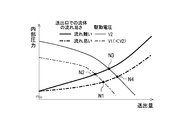
- FIG. 3 is a graph showing a change in the internal pressure of the fluid delivery device with respect to the fluid delivery rate.
- FIG. 4 is a graph showing changes in the rotational speed with respect to the torque of the DC motor.
- FIG. 5 is a graph showing another example of the drive characteristics of the DC motor in the present embodiment.
- FIG. 6 is a flowchart for explaining an example of the open loop control of the DC motor according to the ease of fluid flow at the delivery port.
- FIG. 7 is a graph showing an example of the drive characteristics of the DC motor in the modification.
- the threshold value of the rotational speed N of the DC motor 2 at each driving voltage V is referred to as a threshold rotational speed.
- the threshold rotational speed to be compared when the rotational speed N increases is called the upper threshold rotational speed NsH
- the threshold rotational speed to be compared when the rotational speed N decreases is the lower threshold rotational speed.
- FIG. 1A is a schematic configuration diagram of a fluid delivery device 100 in the present embodiment.
- FIG. 1B is a block diagram showing a configuration of the fluid delivery device 100 in the present embodiment.
- the fluid delivery device 100 delivers the fluid F sucked from the suction port 3a from the delivery port 3b. Moreover, as will be described later, the ease of flow of the fluid F at the delivery port 3b can be changed.
- the fluid F is air
- the fluid delivery device 100 is a blower such as a hair dryer.
- the fluid F may be a gas other than air or a liquid.
- the fluid delivery device 100 may be a blower other than a hair dryer, or a pump device that performs suction and delivery of the fluid F. *
- the fluid delivery device 100 includes an impeller 1, a DC motor 2, and a housing 3. *
- the impeller 1 has blades (not shown) that can rotate around a central axis.
- the impeller 1 can rotate around the central axis, and the fluid F flows from the suction port 3a to the delivery port 3b by the rotation.
- the DC motor 2 is driven by a plurality of drive voltages V and rotates the impeller 1.
- the DC motor 2 includes a rotor 21, a stator 22, a drive driver 23, a rotation speed detection unit 24, a power supply unit 25, and a control device 4.
- the fluid delivery device 100 further includes the control device 4.
- the drive driver 23, the rotation speed detection unit 24, and the power supply unit 25 may be mounted on the control device 4 without being limited to the example illustrated in FIG. 1B.
- the control device 4 will be described later. *
- the impeller 1 is attached to the rotor 21.
- the rotor 21 can rotate together with the impeller 1 about the central axis.
- the rotational speed N of the rotor 21 may be referred to as the rotational speed N of the DC motor 2.
- the stator 22 rotates the rotor 21 based on the drive voltage V supplied from the drive driver 23.
- the DC motor 2 may be expressed as being driven by the drive voltage V, but this expression means that the rotor 21 is driven and rotated by supplying the drive voltage V to the stator 22. . *
- the drive driver 23 generates a drive voltage V based on the drive voltage control signal output from the control device 4 and outputs the drive voltage V to the stator 22.
- the rotation speed detection unit 24 detects the rotation speed N of the rotor 21 and outputs a rotation speed signal to the control device 4 based on the detection result.
- the rotation speed detection unit 24 detects the rotation speed N based on a back electromotive voltage generated in the DC motor 2 when the rotor 21 rotates.
- the means for detecting the rotational speed N is not limited to this example.
- the rotation speed detection unit 24 may be configured to include an element for detecting the rotation speed N, such as a Hall IC. *
- the power supply unit 25 is a power supply source for the DC motor 2.
- the power supply unit 25 receives supply of power from the outside of the DC motor 2 and supplies power to each component of the DC motor 2, such as the drive driver 23 and the control device 4. Further, the power supply unit 25 outputs a power supply voltage signal indicating the power supply voltage of the power supply supplied from the outside of the DC motor 2 to the control device 4.
- the housing 3 accommodates the impeller 1.
- the housing 3 further houses the DC motor 2.
- the housing 3 is provided with a suction port 3a through which the fluid F is sucked and a delivery port 3b through which the fluid F is delivered.
- the housing 3 has a suction port 3a and a delivery port 3b.
- a delivery changing member 31 that changes the ease of flow of the fluid F can be attached to and detached from the delivery port 3b.
- the delivery changing member 31 is, for example, a nozzle that limits the delivery amount of the fluid F delivered from the delivery port 3b, and changes the ease of flow of the fluid F at the delivery port 3b in two stages. Therefore, when the delivery changing member 31 is attached to the delivery port 3b, the delivery amount of the fluid F delivered from the delivery port 3b is smaller than when the delivery change member 31 is not attached.
- the fluid delivery device 100 includes a delivery change member 31.
- the housing 3 may include the delivery changing member 31 without being limited to this example. That is, the delivery changing member 31 may be a part of the housing 3. Further, the delivery changing member 31 is not limited to the above example, and may be a member that increases the delivery amount of the fluid F at the delivery port 3b by attachment. *
- the fluid delivery device 100 described above controls the impeller 1 having blades that can rotate around the central axis, the DC motor 2 that rotates the impeller 1, the housing 3 that houses the impeller 1, and the drive of the DC motor 2. And a control device 4 for performing.
- the housing 3 has a delivery port 3b through which the fluid F is delivered.
- a delivery changing member 31 that changes the flowability of the fluid F stepwise can be attached to and detached from the delivery port 3b.
- the rotational speed N of the DC motor 2 can be automatically changed by the control device 4 performing open-loop control of the driving of the DC motor 2 in accordance with the attachment / detachment of the delivery changing member 31 as described later. it can.
- the driving of the DC motor 2 can be controlled with a simple configuration.
- the control device 4 controls the DC motor 2 that rotates the impeller 1 that flows the fluid F from the suction port 3a to the delivery port 3b in the fluid delivery device 100 in which the flow ease of the fluid F at the delivery port 3b can be changed.
- the control device 4 controls the driving of the DC motor 2 using the program and information stored in the memory. More specifically, the control device 4 outputs a drive voltage control signal to the drive driver 23, thereby controlling the drive voltage V supplied to the stator 22 and controlling the rotational drive of the rotor 21.
- the memory is a non-transitory storage medium that maintains storage even when power is not supplied.
- the memory may be a storage unit 431 described later, or may be a storage medium (not shown) provided in the control device 4 or the DC motor 2 in addition to the storage unit 431.
- At least one of the control apparatus 4 and the above-mentioned memory may be provided outside the DC motor 2.
- at least one of the control device 4 and the above-described memory may be accommodated in the housing 3 together with the impeller 1 and the DC motor 2 or may be provided outside the housing 3.
- control device 4 includes a drive control unit 41, a reception unit 42, and a determination unit 43.
- the drive control unit 41 controls the drive voltage V supplied to the stator 22 of the DC motor 2 by outputting a drive voltage control signal to the drive driver 23.
- the DC motor 2 is driven with a plurality of drive voltages V.
- the plurality of drive voltages V include a first drive voltage V1 and a second drive voltage V2 that is higher than the first drive voltage. That is, the DC motor 2 is driven by either the first drive voltage or the second drive voltage V2.
- the receiving unit 42 receives various signals. For example, the receiving unit 42 receives a rotation number signal from the rotation number detection unit 24 and receives a power supply voltage signal from the power supply unit 25.
- the rotation speed signal is a signal indicating the rotation speed N of the DC motor 2.
- the power supply voltage signal is a signal indicating the power supply voltage of the DC motor 2.
- the determination unit 43 performs various determinations. For example, the determination unit 43 determines whether the flowability of the fluid F at the delivery port 3b has changed based on the rotation speed signal received by the reception unit 42. As illustrated in FIG. 1B, the determination unit 43 includes a storage unit 431, a calculation unit 432, and a timer 433. *
- storage part 431 memorize
- the storage unit 431 stores a plurality of drive voltages V for driving the DC motor 2 and threshold rotation speeds when the DC motor 2 is driven with each drive voltage V.
- the storage unit 431 stores the rotational speed N received in the receiving unit 42 in time series.
- the rotation speed N is memorize
- the calculation unit 432 performs various calculations, and particularly performs various calculations using data indicated by various signals received by the receiving unit 42 and data stored in the storage unit 432. For example, the calculation unit 432 calculates a power supply voltage difference between a preset voltage such as the rated voltage of the power supply source and the power supply voltage indicated by the power supply voltage signal received by the reception unit 42. The calculation unit 432 also designs the rotational speed N indicated by the rotational speed signal when the DC motor 2 is driven at a predetermined driving voltage V and the rotational speed N of the DC motor 2 corresponding to the predetermined driving voltage V, which will be described later. Calculate the rotational speed difference from the value. *
- the timer 433 acquires the date and time at each time point, measures the elapsed time from a predetermined time point to another predetermined time point, and the like.
- FIG. 2 is a graph showing an example of drive characteristics of the DC motor 2 in the present embodiment.
- FIG. 3 is a graph showing a change in internal pressure of the fluid delivery device 100 with respect to the delivery amount of the fluid F.
- FIG. 4 is a graph showing a change in the rotational speed N with respect to the torque of the DC motor 2.
- FIG. 5 is a graph showing another example of the drive characteristics of the DC motor 2 in the present embodiment.
- the “ease of flow in two stages” means that the fluid F easily flows at the outlet 3b when the delivery changing member 31 is attached to the delivery port 3b, and the delivery changing member 31 is attached to the delivery port 3b.
- the fluid F is less likely to flow through the delivery port 3b than when the delivery changing member 31 is not attached to the delivery port 3b.
- the first rotation speed N1 is a design value of the rotation speed N of the DC motor 2 driven by the first drive voltage V1 when the fluid F is likely to flow through the delivery port 3b.
- the second rotation speed N2 is a design value of the rotation speed N of the DC motor 2 driven by the first drive voltage V1 when the fluid F is difficult to flow at the delivery port 3b.
- the third rotation speed N3 is a design value of the rotation speed N of the DC motor 2 driven by the second drive voltage V2 when the fluid F is difficult to flow at the delivery port 3b.
- the fourth rotation speed N4 is a design value of the rotation speed N of the DC motor 2 that is driven by the second drive voltage V2 when the fluid F easily flows at the outlet 3b.
- the “design value” of the rotational speed N is a standard value of the rotational speed N of the DC motor 2 driven by each driving voltage V, and individual differences of the DC motor 2 and changes in performance over time. This is the rotational speed N when no consideration is given. Therefore, in actual control, as will be described later, the actual rotational speed N indicated by the rotational speed signal in the DC motor 2 driven by each driving voltage V is the same as that of the DC motor 2 driven by each driving voltage V. It may be different from the design value of the rotational speed N. However, in the present embodiment, the description will be made on the assumption that the actual rotational speed N is the same as the design value of the rotational speed N unless there is a special description or contradiction for easy understanding of the contents. *
- the control device 4 changes the drive voltage V according to the ease of flow of the fluid F at the delivery port 3b. More specifically, the drive control part 41 raises the drive voltage V, if the rotation speed N of the DC motor 2 increases when the ease of flow of the fluid F at the delivery port 3b changes. In addition, the drive control unit 41 reduces the drive voltage V when the rotational speed N of the DC motor 2 decreases when the ease of flow of the fluid F at the outlet 3b changes. For example, in the present embodiment, the drive control unit 41 changes the drive voltage V from the first drive voltage V1 to the second drive voltage V2 when the delivery changing member 31 is attached to the delivery port 3b.
- the drive control unit 41 changes the drive voltage V from the second drive voltage V2 to the first drive voltage V1.
- the drive voltage V may change immediately or may change gradually.
- the control device 4 uses the characteristic that the rotational speed N of the DC motor 2 changes with respect to the change in the ease of flow of the fluid F at the delivery port 3b, so that the fluid F easily flows at the delivery port 3b. It is determined whether or not the value has changed.
- the ease of flow of the fluid F at the delivery port 3b changes by performing open-loop control of the driving of the DC motor 2
- the rotational speed N of the DC motor 2 changes. Therefore, for example, there is no need to provide a control element or a means for operating the element, and therefore the driving of the DC motor 2 can be controlled with a simple configuration.
- the drive control unit 41 performs PWM control of the drive voltage V. More specifically, the drive control unit 41 changes the PWM control value of the drive voltage V indicated by the drive voltage control signal output to the drive driver 23.
- the drive control unit 41 increases the PWM control value of the drive voltage V.
- the drive control unit 41 decreases the PWM control value of the drive voltage V.
- the drive control unit 41 increases the PWM duty indicated by the drive voltage control signal from 53% to 64%, for example.
- the drive control unit 41 when the delivery changing member 31 is removed from the delivery port 3b, the drive control unit 41 reduces the PWM duty indicated by the drive voltage control signal from 64% to 53%, for example. In this way, the drive voltage V can be PWM controlled. Note that how to change the PWM control value is not particularly limited. For example, the PWM control value may be changed immediately or gradually. *
- the drive control unit 41 drives the DC motor 2 with any one of a plurality of drive voltages V including the minimum first drive voltage V1 and the maximum second drive voltage V2. In this way, the DC motor 2 can be driven at the rotation speed N corresponding to each drive voltage V.
- Each drive voltage V is set with at least one of the upper threshold rotational speed NsH and the lower threshold rotational speed NsL of the rotational speed N.
- the upper threshold rotation speed NsH1 is set for the first drive voltage V1.
- the lower threshold rotation speed NsL2 is set for the second drive voltage V2.
- the upper threshold rotational speed NsH of the rotational speed N of the DC motor 2 and the DC before the ease of flow of the fluid F at the outlet 3b decreases by one step.
- the difference from the rotational speed N of the motor 2 is preferably the upper threshold rotational speed of the rotational speed N after the ease of flow of the fluid F at the delivery port 3b decreases by one step and the rotational speed N of the DC motor 2. It is larger than the difference from NsH.
- the rotational speed N of the DC motor 2 before the ease of flow of the fluid F at the delivery port 3b is increased by one step
- the lower threshold rotational speed NsL of the rotational speed N of the DC motor 2 Preferably, the difference between the lower threshold rotational speed NsL of the rotational speed N of the DC motor 2 and the rotational speed N after the ease of flow of the fluid F at the delivery port 3b is increased by one step. Is also big. *
- the rotational speed N of the DC motor 2 driven by the driving voltage V after the open loop control exceeds the threshold rotational speed after the open loop control. May be maintained.
- control for increasing the drive voltage V and control for decreasing the drive voltage V are repeatedly performed.
- the rotational speed N of the DC motor 2 driven by the first drive voltage V1 is larger than the upper threshold rotational speed NsH1, and the rotational speed N of the DC motor 2 driven by the second drive voltage V2 Is smaller than the lower threshold rotational speed NsL2.
- control for changing the drive voltage V from the first drive voltage V1 to the second drive voltage V2 and the control for changing the drive voltage V from the second drive voltage V2 to the first drive voltage V1 are repeatedly performed.
- the rotational speed N of the DC motor 2 may frequently increase or decrease.
- the difference between the upper threshold rotation speed NsH1 and the first rotation speed N1 is larger than the difference between the second rotation speed N2 and the upper threshold rotation speed NsH1. That is,
- the difference between the third rotation speed N3 and the lower threshold rotation speed NsL2 is greater than the difference between the lower threshold rotation speed NsL2 and the fourth rotation speed N4 at the second drive voltage V2. That is,
- the upper threshold rotational speed NsH1 is closer to the second rotational speed N2 than the first rotational speed N1
- the lower threshold rotational speed NsL2 is the fourth rotational speed N4 than the third rotational speed N3. Therefore, frequent repetition of the open loop control of the drive voltage V can be prevented.
- the present invention is not limited to the above example, and before each drive voltage V, the upper threshold rotational speed NsH of the rotational speed N of the DC motor 2 and the ease of flow of the fluid F at the outlet 3b are reduced by one step.
- the difference from the rotational speed N of the DC motor 2 is that the rotational speed N after the ease of flow of the fluid F at the outlet 3b decreases by one step, and the upper threshold rotational speed NsH of the rotational speed N of the DC motor 2 Or less than the difference.
- the rotational speed N of the DC motor 2 before the ease of flow of the fluid F at the delivery port 3b is increased by one step
- the lower threshold rotational speed NsL of the rotational speed N of the DC motor 2 Is less than the difference between the lower threshold rotational speed NsL of the rotational speed N of the DC motor 2 and the rotational speed N after the ease of flow of the fluid F at the delivery port 3b is increased by one step. Also good.
- may be satisfied, or
- may be satisfied, or
- may be satisfied as shown in FIG. *
- FIG. 6 is a flowchart for explaining an example of open loop control of the DC motor 2 in accordance with the ease of flow of the fluid F at the delivery port 3b.
- the process is started in a state in which the delivery changing member 31 is not attached to the delivery port 3b and it is determined that the fluid F easily flows through the delivery port 3b.
- the control device 4 starts the operation of FIG. First, the drive control unit 41 sets the drive voltage V to the first drive voltage V1 as an initial value (S101). Then, a drive voltage control signal for changing the drive voltage V to the first drive voltage V1 is output to the drive driver 23, and the DC motor 2 is driven with the first drive voltage V1.
- the determination unit 43 determines whether or not the power supply voltage difference between the preset voltage and the power supply voltage is 0 (S102). More specifically, the receiving unit 42 receives a power supply voltage signal. The calculation unit 432 calculates the power supply voltage difference between the rated voltage of power supplied from the outside of the DC motor 2 to the power supply unit 25 and the power supply voltage of the power supply voltage signal, for example. The determination unit 43 determines whether or not the power supply voltage difference is zero. If the power supply voltage difference is 0 (YES in S102), the process proceeds to S104 described later.
- the determination unit 43 determines the threshold rotation speeds at the respective drive voltages V, that is, the upper threshold rotation speed NsH1 and the lower threshold rotation speed NsL2 based on the power supply voltage difference. Adjust (S103). Then, the process proceeds to S104. *
- the DC motor 2 is driven with the first drive voltage V1.
- the determination unit 43 determines whether or not the rotation speed N of the rotation speed signal received by the reception unit 41 is increasing. If the rotational speed N has not increased (NO in S110), the process returns to S102.
- the determination unit 43 determines whether the rotational speed N of the rotational speed signal received by the receiving unit 41 is greater than the upper threshold rotational speed NsH1 at the first drive voltage V1. It is determined whether or not (S111). If N> NsH1 is not satisfied (NO in S111), the process returns to S102. If N> NsH1 (YES in S111), the determination result of the determination unit 43 changes (S112). In other words, the determination unit 43 determines that the ease of flow of the fluid F at the delivery port 3b is lowered by one step, and the fluid F is less likely to flow at the delivery port 3b. *
- the determination part 43 further determines whether this determination result is maintained longer than the predetermined 1st time (S113).
- 1st time is 2.0 [sec] in this embodiment, for example, it is not limited to this illustration. If the determination result is not maintained longer than the first time (NO in S113), the process returns to S102. When the determination result is maintained longer than the first time (YES in S113), the drive control unit 41 increases the drive voltage V by the output of the drive voltage control signal to obtain the second drive voltage V2 (S114). ).
- the determination part 43 determines whether the rotation speed difference after the raise of the drive voltage V is 0 (S115).
- the rotation speed difference here is driven by the actual third rotation speed N3 indicated by the rotation speed signal received by the receiving unit 42 after the drive voltage V is raised to the second drive voltage V2 and the second drive voltage V2. This is a difference from the design value of the third rotation speed N3 of the DC motor 2 to be performed. If the rotational speed difference is 0 (YES in S115), the process proceeds to S140 described later. On the other hand, if the rotational speed difference is not 0 (NO in S115), the process proceeds to S130 described later. *
- the determination unit 43 determines whether or not the rotation speed N of the rotation speed signal received by the reception unit 41 is decreasing. If the rotational speed N has not decreased (NO in S120), the process returns to S102. When the rotational speed N is decreasing (YES in S120), the determination unit 43 determines that the rotational speed N of the rotational speed signal received by the receiving unit 41 is smaller than the lower threshold rotational speed NsL2 at the second drive voltage V2. It is determined whether or not (S121). If N ⁇ NsL2 is not satisfied (NO in S121), the process returns to S102.
- the determination result of the determination unit 43 changes (S122). That is, the determination unit 43 determines that the ease of flow of the fluid F at the delivery port 3b is increased by one step, and the fluid F is easier to flow at the delivery port 3b.
- the determination unit 43 further determines whether or not the determination result is maintained longer than a predetermined second time (S123).
- 2nd time is 1.5 [sec] in this embodiment, for example, it is not limited to this illustration. If the determination result is not maintained longer than the second time (NO in S123), the process returns to S102.
- the drive control unit 41 reduces the drive voltage V to the first drive voltage V1 by the output of the drive voltage control signal (S124). ).
- the determination part 43 determines whether the rotation speed difference after the drive voltage V falls is 0 (S125).
- the rotational speed difference here is driven by the actual first rotational speed N1 indicated by the rotational speed signal received by the receiving unit 42 after the drive voltage V is lowered to the first drive voltage V1 and the first drive voltage V1. This is a difference from the design value of the first rotation speed N1 of the DC motor 2 to be performed. If the rotational speed difference is 0 (YES in S125), the process proceeds to S140 described later. On the other hand, if the rotation speed difference is not 0 (NO in S125), the process proceeds to S130 described later. *
- the determination unit 43 adjusts the threshold rotation speed at each drive voltage V, that is, the upper threshold rotation speed NsH1 and the lower threshold rotation speed NsL2 based on the rotation speed difference. Then, the process proceeds to S140. *
- the determination unit 43 determines whether the power of the fluid delivery device 100 is OFF. If the power is not OFF (NO in S140), the process returns to S102. If the power is off (YES in S140), the process in FIG. 6 ends. *
- At least one of S102 and S103, S113, S123, S115, S125, and S130 may be omitted. Even in this way, the control device 4 can perform the open loop control of the DC motor 2.
- the determination unit 43 adjusts the upper threshold rotation speed NsH and the lower threshold rotation speed NsL at each drive voltage V based on the power supply voltage difference between the preset voltage and the power supply voltage. . For example, if the power supply voltage difference is not 0 in S102, the upper threshold rotation speed NsH1 of the first drive voltage V1 and the lower threshold rotation speed NsL2 of the second drive voltage V2 are adjusted according to the power supply voltage difference in S103, respectively. The If it does in this way, rotation speed N of DC motor 2 will fluctuate by change of power supply voltage.
- the fluid delivery device 100 delivers the fluid. Variations also occur in the amount. Therefore, by adjusting the upper threshold rotational speed NsH1 and the lower threshold rotational speed NsL2 based on the power supply voltage difference, the driving voltage depends on whether or not the fluid F easily flows at the outlet 3b. It is possible to control V more accurately and more stably. Therefore, the fluctuation
- the drive control unit 41 changes the drive voltage V to the first drive voltage V1 when the rotation speed N of the DC motor 2 driven by the first drive voltage V1 becomes larger than the upper threshold rotation speed NsH1.
- the driving voltage V is increased to a larger value.
- the drive control unit 41 maintains the drive voltage V at the first drive voltage V1. For example, when N> NsH1 in S111, the drive control unit 41 increases the drive voltage V to the second drive voltage V2 (> V1) in S114.
- the DC motor 2 is driven with the minimum first drive voltage V1.
- the drive control unit 41 increases the drive voltage V to a drive voltage V greater than the first drive voltage V1. Raise.
- the rotation speed N of the DC motor 2 increases to the rotation speed N when the fluid F becomes difficult to flow at the outlet 3b at the drive voltage V after the increase.
- the drive control unit 41 increases the drive voltage V to the second drive voltage V2 that is higher than the first drive voltage V1
- the rotation speed N increases to the third rotation speed N3. Therefore, since the delivery amount of the fluid F increases, it is possible to suppress an excessive decrease in the delivery amount due to the difficulty in flowing the fluid F at the delivery port 3b. Therefore, the delivery amount of the fluid delivery device 100 can be satisfactorily adjusted by simple control.
- the drive control unit 41 changes the drive voltage V to the second drive voltage.
- the drive voltage V is lowered to a value smaller than V2. If the rotation speed N of the DC motor 2 driven by the second drive voltage V2 is equal to or higher than the lower threshold rotation speed NsL2, the drive control unit 41 maintains the drive voltage V at the second drive voltage V2. For example, when N ⁇ NsL2 in S121, the drive control unit 41 reduces the drive voltage V to the first drive voltage V1 ( ⁇ V2) in S124.
- the drive control unit 41 sets the drive voltage V to a drive voltage smaller than the second drive voltage V2. Reduce to V.
- the rotational speed N of the DC motor 2 decreases to the rotational speed N when the fluid F easily flows at the delivery port 3b after the drive voltage V decreases.
- the drive control unit 41 reduces the drive voltage V to the first drive voltage V1 that is smaller than the second drive voltage V2
- the rotational speed N decreases to the first rotational speed N1. Therefore, since the delivery amount of the fluid F decreases, it is possible to suppress an excessive increase in the delivery amount caused by the fluid F easily flowing at the delivery port 3b. Therefore, the delivery amount of the fluid delivery device 100 can be satisfactorily adjusted by simple control.
- the drive control unit 41 sets the drive voltage V if the time during which the determination result after the change is maintained is longer than a predetermined time from the time when the determination result of the determination unit 43 changes. Change.
- the drive control unit 41 maintains the drive voltage V when the time during which the determination result after the change is maintained is equal to or less than a predetermined time from when the determination result of the determination unit 43 changes. For example, from the point of S112 when the determination result of the determination unit 43 is changed, if the determination result after the change is maintained in S113 longer than a predetermined first time, the drive control unit 41 is as in S114. The drive voltage V is increased.
- the drive control unit 41 determines No in S113.
- the drive voltage V is not increased as in the case. If the determination result after the change in S123 is maintained longer than the predetermined second time from the time of S122 when the determination result of the determination unit 43 is changed, the drive control unit 41 is as in S124. The drive voltage V is reduced. On the other hand, if the determination result after the change in S123 is not maintained longer than the predetermined second time from S122 when the determination result of the determination unit 43 is changed, the drive control unit 41 determines No in S123. The drive voltage V is not lowered as in the case.
- the temporary change in the rotational speed N hardly affects the drive control of the DC motor 2.
- the drive control unit No. 41 does not change the drive voltage V. Therefore, the DC motor 2 can be controlled more stably.
- the time for which the determination result after the change is maintained is from S112 when the determination result of the determination unit 43 is changed to S113. If it is maintained longer than the predetermined first time, the drive control unit 41 increases the drive voltage V. On the other hand, if the time during which the determination result after the change is maintained in S111 is equal to or less than the first time predetermined in S113 from the time of S112 when the determination result of the determination unit 43 has changed, the drive control unit 41 The drive voltage V is maintained.
- the time for which the determination result after the change is maintained is determined in advance in S123 from the time of S122 when the determination result of the determination unit 43 is changed. If it is maintained longer than the set second time, the drive control unit 41 reduces the drive voltage V. On the other hand, if the time during which the determination result after the change is maintained in S121 is equal to or shorter than the second time predetermined in S123 from the time of S122 when the determination result of the determination unit 43 is changed, the drive control unit 41 The drive voltage V is maintained. At this time, the first time in S113 is preferably longer than the second time in S123.
- the time corresponding to the shortage in the case of increasing the rotational speed N becomes longer than in the case of decreasing the rotational speed N. Therefore, it is effective, for example, when the temporary clogging of the delivery port 3b of the fluid delivery device 100 is eliminated.
- the present invention is not limited to this example, and the first time in S113 may be the same as the second time in S123, or may be shorter than the second time in S123.
- the determination unit 43 is a DC motor that is driven with the rotational speed N of the DC motor 2 indicated by the rotational speed signal when the DC motor 2 is driven with the predetermined driving voltage V and the predetermined driving voltage V.
- the upper threshold rotational speed NsH and the lower threshold rotational speed NsL of the DC motor 2 at each drive voltage V are adjusted based on the rotational speed difference from the design value of the rotational speed N of 2. For example, if the rotation speed difference is not 0 in S115, the upper threshold rotation speed NsH1 of the first drive voltage V1 is adjusted in S130 according to the rotation speed difference.
- the determination unit 43 changes the rotational speed N at each driving voltage V.
- the upper threshold rotational speed NsH and the lower threshold rotational speed NsL are adjusted to smaller values, for example, the upper threshold rotational speed NsH and the lower threshold rotational speed NsL, which are obtained by subtracting the rotational speed difference between them.
- the determination unit 43 determines the upper threshold rotation speed NsH and the lower threshold rotation speed NsL of the DC motor 2. Is adjusted to a larger value, for example, a value obtained by adding the rotational speed difference between the upper threshold rotational speed NsH and the lower threshold rotational speed NsL. Therefore, the determination unit 43 can determine whether or not the ease of flow of the fluid F at the outlet 3b has changed using the adjusted upper threshold rotation speed NsH and lower threshold rotation speed NsL.
- the determination unit 43 adjusts the upper threshold rotational speed NsH and the lower threshold rotational speed NsL using the rotational speed difference as described above, so that the threshold rotational speed N of the DC motor 2 at each drive voltage V is more optimal. Can be adjusted. Therefore, it is possible to mitigate or eliminate the influence of the difference in performance of each DC motor 2 and the change in performance due to aging on the drive control of the DC motor 2. Therefore, more stable drive control of the DC motor 2 can be performed.
- the DC motor 2 since the ease of flow of the fluid F at the delivery port 3 changes in two stages, the DC motor 2 has two drive voltages V including the first drive voltage V1 and the second drive voltage V2. Driven by either.
- the present invention is not limited to this example, and the DC motor 2 may be driven with three or more driving voltages V. In this way, even when the flowability of the fluid F at the outlet 3 changes in multiple stages of 3 or more, the drive of the DC motor 2 can be controlled in an open loop, and the rotational speed Na of the DC motor 2 is automatically changed. Can be made.
- FIG. 7 is a graph showing an example of drive characteristics of the DC motor 2 in the modification.
- the drive voltage V includes a third drive voltage V3 in addition to the minimum first drive voltage V1 and the maximum second drive voltage V2.
- the third drive voltage V3 is larger than the first drive voltage V1 and smaller than the second drive voltage V2.
- FIG. 7 shows drive characteristics when the ease of flow of the fluid F at the delivery port 3b changes in three stages.
- the first rotation speed Na1 is a design value of the rotation speed Na of the DC motor 2 driven with the minimum first drive voltage V1 when the fluid F is most likely to flow at the outlet 3b.
- the second rotation speed Na2 is a design value of the rotation speed Na of the DC motor 2 driven with the minimum first drive voltage V1 when the fluid F easily flows at the outlet 3b.
- the third rotation speed Na3 is a design value of the rotation speed Na of the DC motor 2 driven by the third drive voltage V3 when the fluid F easily flows at the outlet 3b.
- the fourth rotation speed Na4 is a design value of the rotation speed Na of the DC motor 2 that is driven by the third drive voltage V3 when the fluid F is most likely to flow through the delivery port 3b.
- the fifth rotation speed Na5 is a design value of the rotation speed Na of the DC motor 2 that is driven by the third drive voltage V3 when the fluid F is most difficult to flow at the delivery port 3b.
- the sixth rotation speed Na6 is a design value of the rotation speed Na of the DC motor 2 that is driven by the maximum second drive voltage V2 when the fluid F is most difficult to flow at the delivery port 3b.
- the seventh rotation speed Na7 is a design value of the rotation speed Na of the DC motor 2 that is driven by the maximum second drive voltage V2 when the fluid F easily flows at the outlet 3b.
- the actual rotational speed Na indicated by the rotational speed signal in the DC motor 2 driven by each driving voltage V is designed to be the rotational speed Na of the DC motor 2 driven by each driving voltage V. May differ from value.
- the description will be made on the assumption that the actual rotation speed Na is the same as the design value of the rotation speed Na unless there is a special description or contradiction in order to make the contents easy to understand.
- Each drive voltage V is set with at least one of an upper threshold rotation speed NsH and a lower threshold rotation speed NsL of the rotation speed Na.
- the upper threshold rotation speed NsH1 is set for the first drive voltage V1.
- the lower threshold rotation speed NsL2 is set for the second drive voltage V1.
- an upper threshold rotation speed NsH3 and a lower threshold rotation speed NsL3 are set.
- the difference between the upper threshold rotational speed NsH1 and the first rotational speed Na1 is preferably larger than the difference between the second rotational speed Na2 and the upper threshold rotational speed NsH1.
- the difference between the sixth rotation speed Na6 and the lower threshold rotation speed NsL2 is preferably larger than the difference between the lower threshold rotation speed NsL2 and the seventh rotation speed Na7.
- the difference between the third rotation speed Na3 and the lower threshold rotation speed NsL3 is preferably larger than the difference between the lower threshold rotation speed NsL3 and the fourth rotation speed Na4.
- the difference between the upper threshold rotational speed NsH3 and the third rotational speed Na3 is preferably larger than the difference between the fifth rotational speed Na5 and the upper threshold rotational speed NsH3.
- the drive voltage V is increased. Note that if the time during which the increased rotation speed Na is maintained to be greater than the upper threshold rotation speed NsH1 is equal to or shorter than the first time, the drive control unit 41 maintains the drive voltage V. As a result, the rotational speed Na of the DC motor 2 increases to a third rotational speed Na3 that is greater than the second rotational speed Na2. Therefore, since the delivery amount of the fluid F increases, it is possible to suppress an excessive decrease in the delivery amount due to the difficulty in flowing the fluid F at the delivery port 3b.
- the drive control unit 41 reduces the drive voltage V to the first drive voltage V1 that is smaller than the third drive voltage V3.
- the drive control unit 41 may immediately decrease the drive voltage V.
- the state in which the reduced rotation speed Na is smaller than the lower threshold rotation speed NsL3 is longer than the predetermined second time. When it is maintained for a long time, the drive voltage V is lowered.
- the drive control unit 41 maintains the drive voltage V if the time during which the reduced rotation speed Na is maintained to be smaller than the lower threshold rotation speed NsL3 is equal to or shorter than the second time.
- the rotational speed Na of the DC motor 2 decreases to the first rotational speed Na1 that is smaller than the fourth rotational speed Na4. Therefore, since the delivery amount of the fluid F decreases, it is possible to suppress an excessive increase in the delivery amount caused by the fluid F easily flowing at the delivery port 3b.
- the drive control unit 41 increases the drive voltage V to the second drive voltage V2 that is larger than the third drive voltage V3.
- the drive control unit 41 may immediately increase the drive voltage V.
- the state in which the increased rotational speed Na is greater than the upper threshold rotational speed NsH3 is longer than the predetermined first time. When it is maintained, the drive voltage V is increased.
- the drive control unit 41 maintains the drive voltage V.
- the rotational speed Na of the DC motor 2 increases to a sixth rotational speed Na6 that is greater than the fifth rotational speed Na5. Therefore, since the delivery amount of the fluid F further increases, it is possible to suppress an excessive decrease in the delivery amount caused by the fluid F becoming more difficult to flow at the delivery port 3b.
- the first time may be equal to or shorter than the second time, but is preferably longer than the second time. In this way, as the rotational speed Na of the DC motor 2 is higher, the time until the drive voltage V changes becomes longer. For example, it becomes easier to obtain time corresponding to an unexpected situation. *
- the DC motor 2 is driven with the maximum second drive voltage V2.
- the drive control unit 41 sets the second drive voltage The drive voltage V is lowered to the third drive voltage V3 that is smaller than V2.
- the drive control unit 41 may immediately decrease the drive voltage V.
- the state in which the reduced rotation speed Na is smaller than the lower threshold rotation speed NsL2 is greater than the predetermined second time. When it is maintained for a long time, the drive voltage V is lowered.
- the drive control unit 41 maintains the drive voltage V if the time during which the reduced rotation speed Na is maintained to be smaller than the lower threshold rotation speed NsL2 is equal to or shorter than the second time.
- the rotational speed Na of the DC motor 2 decreases to a third rotational speed Na3 that is smaller than the seventh rotational speed Na7. Therefore, since the delivery amount of the fluid F decreases, it is possible to suppress an excessive increase in the delivery amount caused by the fluid F easily flowing at the delivery port 3b.
- the delivery amount of the fluid delivery device 100 can be adjusted favorably by simple control. *
- the plurality of drive voltages V further include at least one third drive voltage V3 that is higher than the first drive voltage V1 and lower than the second drive voltage V2.
- the drive control unit 41 changes the drive voltage V to a drive voltage V greater than the third drive voltage V3. Raise.
- the drive control section 41 sets the drive voltage V to the third drive voltage. Maintain at V3.
- the rotational speed Na is decreased to the first rotational speed Na1, and the delivery amount of the fluid F is decreased. Therefore, it is possible to suppress an excessive increase in the delivery amount due to the fluid F easily flowing at the delivery port 3b. Therefore, the delivery amount of the fluid delivery device 100 can be adjusted more satisfactorily by simple control.
- This invention is useful for control of the motor mounted in the fluid delivery apparatus which can attach or detach the member which changes the easiness of a fluid flow to a delivery outlet.
Landscapes
- Engineering & Computer Science (AREA)
- Power Engineering (AREA)
- Control Of Direct Current Motors (AREA)
- Structures Of Non-Positive Displacement Pumps (AREA)
Abstract
流体送出装置は、流体を吸引口から送出口に流すインペラと、インペラを回転させるDCモータと、インペラを収容するハウジングと、DCモータの制御装置と、を備える。ハウジングの送出口には、流体の流れ易さを変化させる送出変化部材が着脱可能である。そのため、送出口での流体の流れ易さが変化可能である。制御装置は、DCモータのステータに供給される駆動電圧を制御する駆動制御部と、DCモータの回転数を示す回転数信号を受信する受信部と、回転数信号に基づいて、送出口での流体の流れ易さが変化したか否かを判定する判定部と、を備える。送出口での流体の流れ易さが変化した場合に回転数が増加すると、駆動制御部は駆動電圧を上昇させる。送出口での流体の流れ易さが変化した場合に回転数が減少すると、駆動制御部は駆動電圧を低下させる。
Description
本発明は、制御装置、流体送出装置に関する。
従来、モータによるインペラの回転駆動により気流を送出する装置が知られている。たとえば、特許文献1は、吹出口の断面積に応じて出力を変更するヘアードライヤーを教示している。このヘアードライヤーでは、集風器を本体の吹出口に取り付けると、集風器の取り付け深さに応じて、マイクロスイッチに設けられたスイッチ棒が押し込まれ、回路が切り替わる。これにより、ヘアードライヤーの出力が変更される。
しかしながら、特許文献1では、上述のような複雑な構成に応じて集風器の形状、回路及び回路基板などの変更が必要となる。そのため、部品点数が増えて、製造コストが増大する。また、マイクロスイッチの経時的な状態変化などによって、回路の切り替えがうまくいかなくなる恐れがある。
本発明は、簡易な構成でDCモータの駆動を制御することを目的とする。
本発明の例示的な制御装置は、送出口での流体の流れ易さが変化可能である流体送出装置において、前記流体を吸引口から前記送出口に流すインペラを回転させるDCモータの制御装置である。該制御装置は、前記DCモータのステータに供給される駆動電圧を制御する駆動制御部と、前記DCモータの回転数を示す回転数信号を受信する受信部と、前記受信部が受信する前記回転数信号に基づいて、前記送出口での前記流体の流れ易さが変化したか否かを判定する判定部と、を備える。前記駆動制御部は、前記送出口での前記流体の流れ易さが変化した場合に前記回転数が増加すると、前記駆動電圧を上昇させる。前記駆動制御部は、前記送出口での前記流体の流れ易さが変化した場合に前記回転数が減少すると、前記駆動電圧を低下させる。
本発明の例示的な流体送出装置は、中心軸回りに回転可能な羽根を有するインペラと、前記インペラを回転させるDCモータと、前記インペラを収容するハウジングと、前記DCモータの駆動を制御する上記の制御装置と、を備える。前記ハウジングは、流体が送出される送出口を有する。前記送出口には、前記流体の流れ易さを変化させる送出変化部材が着脱可能である。
本発明の例示的な制御装置、流体送出装置によれば、簡易な構成でDCモータの駆動を制御することができる。
<1.実施形態>
以下に図面を参照して本発明の例示的な実施形態を説明する。
以下に図面を参照して本発明の例示的な実施形態を説明する。
なお、以下では、流体送出装置100において、各々の駆動電圧VにおけるDCモータ2の回転数Nの閾値を閾回転数と呼ぶ。また、各々の駆動電圧Vにおいて、回転数Nが増加する際に比較する閾回転数を上側閾回転数NsHと呼び、回転数Nが減少する際に比較する閾回転数を下側閾回転数NsLと呼ぶ。
<1-1.流体送出装置>
図1Aは、本実施形態における流体送出装置100の概略構成図である。図1Bは、本実施形態における流体送出装置100の構成を示すブロック図である。
図1Aは、本実施形態における流体送出装置100の概略構成図である。図1Bは、本実施形態における流体送出装置100の構成を示すブロック図である。
流体送出装置100は、吸引口3aから吸引する流体Fを送出口3bから送出する。また、後述するように、送出口3bでの流体Fの流れ易さが変化可能である。本実施形態では、流体Fは空気であり、流体送出装置100はたとえばヘアードライヤーなどの送風装置である。但し、これらは、本実施形態の例示に限定されない。たとえば、流体Fは、空気以外の気体、液体であってもよい。また、流体送出装置100は、ヘアードライヤー以外の送風装置であってもよいし、流体Fの吸引及び送出を行うポンプ装置などであってもよい。
流体送出装置100は、インペラ1と、DCモータ2と、ハウジング3と、を備える。
インペラ1は、中心軸回りに回転可能な羽根(図示省略)を有する。インペラ1は、中心軸回りに回転可能であり、回転によって流体Fを吸引口3aから送出口3bに流す。
DCモータ2は、複数の駆動電圧Vで駆動され、インペラ1を回転させる。DCモータ2は、ロータ21と、ステータ22と、駆動ドライバ23と、回転数検出部24と、電源部25と、制御装置4と、を有する。言い換えると、流体送出装置100は、制御装置4をさらに備える。また、図1Bの例示に限定されず、駆動ドライバ23、回転数検出部24、及び電源部25は、制御装置4に搭載されていてもよい。なお、制御装置4については後に説明する。
ロータ21には、インペラ1が取り付けられる。ロータ21は、中心軸を中心として、インペラ1とともに回転可能である。なお、以下では、ロータ21の回転数NをDCモータ2の回転数Nと呼ぶことがある。
ステータ22は、駆動ドライバ23から供給される駆動電圧Vに基づいて、ロータ21を回転させる。なお、以下では、DCモータ2を駆動電圧Vで駆動すると表現することがあるが、この表現は、駆動電圧Vをステータ22に供給することによって、ロータ21が駆動されて回転することを意味する。
駆動ドライバ23は、制御装置4から出力される駆動電圧制御信号に基づいて駆動電圧Vを生成し、該駆動電圧Vをステータ22に出力する。
回転数検出部24は、ロータ21の回転数Nを検出し、検出結果に基づいて回転数信号を制御装置4に出力する。なお、回転数検出部24は、本実施形態ではロータ21が回転する際にDCモータ2に発生する逆起電圧に基づいて回転数Nを検出する。但し、回転数Nの検出手段は、この例に限定されない。たとえば、回転数検出部24は、ホールICなどの回転数Nを検出するための素子を有する構成であってもよい。
電源部25は、DCモータ2の電力供給源である。電源部25は、DCモータ2の外部から電源電力の供給を受け、DCモータ2の各構成要素、たとえば駆動ドライバ23及び制御装置4などに電力を供給する。また、電源部25は、DCモータ2の外部から供給される電源電力の電源電圧を示す電源電圧信号を制御装置4に出力する。
ハウジング3は、インペラ1を収容する。また、本実施形態では、ハウジング3は、DCモータ2をさらに収容する。ハウジング3には、流体Fが吸引される吸引口3aと、流体Fが送出される送出口3bと、が設けられる。言い換えると、ハウジング3は、吸引口3aと送出口3bとを有する。DCモータ2の駆動によりインペラ1が回転すると、流体Fが、吸引口3aを通じてハウジング3の外部から内部に吸引され、送出口3bを通じてハウジング3の内部から外部に送出される。
送出口3bには、流体Fの流れ易さを変化させる送出変化部材31が着脱可能である。送出変化部材31の着脱により、送出口3bでの流体Fの流れ易さは、段階的に変化可能である。送出変化部材31は、本実施形態では、たとえば、送出口3bから送出される流体Fの送出量を制限するノズルであり、送出口3bでの流体Fの流れ易さを2段階に変化させる。そのため、送出変化部材31が送出口3bに取り付けられると、送出口3bから送出される流体Fの送出量は、送出変化部材31が取り付けられていない場合よりも減少する。送出変化部材31が送出口3bから外されると、送出口3bから送出される流体Fの送出量は、送出変化部材31が取り付けられる場合よりも増加する。なお、本実施形態では、流体送出装置100が、送出変化部材31を有する。但し、この例示に限定されず、ハウジング3が、送出変化部材31を有してもよい。つまり、送出変化部材31は、ハウジング3の一部であってもよい。また、送出変化部材31は、上述の例示に限定されず、取り付けにより送出口3bでの流体Fの送出量を増加させる部材であってもよい。
以上に説明した流体送出装置100は、中心軸回りに回転可能な羽根を有するインペラ1と、インペラ1を回転させるDCモータ2と、インペラ1を収容するハウジング3と、DCモータ2の駆動を制御する制御装置4と、を備える。ハウジング3は、流体Fが送出される送出口3bを有する。送出口3bには、流体Fの流れ易さを段階的に変化させる送出変化部材31が着脱可能である。この構成によれば、送出変化部材31の着脱に応じて制御装置4が後述のようにDCモータ2の駆動をオープンループ制御することにより、DCモータ2の回転数Nを自動で変化させることができる。たとえば制御用の素子を設けたり、該素子を操作する手段を設けたりする必要がないので、簡易な構成でDCモータ2の駆動を制御できる。
<1-2.制御装置>
次に、制御装置4について説明する。制御装置4は、送出口3bでの流体Fの流れ易さが変化可能である流体送出装置100において、流体Fを吸引口3aから送出口3bに流すインペラ1を回転させるDCモータ2を制御する装置である。制御装置4は、メモリに格納されたプログラム及び情報を用いて、DCモータ2の駆動を制御する。より具体的には、制御装置4は、駆動ドライバ23に駆動電圧制御信号を出力することによって、ステータ22に供給される駆動電圧Vを制御し、ロータ21の回転駆動を制御する。なお、メモリは、電力供給が無くても記憶を維持する非一過性の記憶媒体である。メモリは、後述する記憶部431であってもよいし、記憶部431以外に制御装置4又はDCモータ2に設けられる記憶媒体(図示省略)であってもよい。但し、本実施形態の例示に限定されず、制御装置4及び上述のメモリの少なくとも一方は、DCモータ2の外部に設けられてもよい。たとえば、制御装置4及び上述のメモリの少なくとも一方は、インペラ1及びDCモータ2とともにハウジング3に収容されてもよいし、ハウジング3の外部に設けられてもよい。
次に、制御装置4について説明する。制御装置4は、送出口3bでの流体Fの流れ易さが変化可能である流体送出装置100において、流体Fを吸引口3aから送出口3bに流すインペラ1を回転させるDCモータ2を制御する装置である。制御装置4は、メモリに格納されたプログラム及び情報を用いて、DCモータ2の駆動を制御する。より具体的には、制御装置4は、駆動ドライバ23に駆動電圧制御信号を出力することによって、ステータ22に供給される駆動電圧Vを制御し、ロータ21の回転駆動を制御する。なお、メモリは、電力供給が無くても記憶を維持する非一過性の記憶媒体である。メモリは、後述する記憶部431であってもよいし、記憶部431以外に制御装置4又はDCモータ2に設けられる記憶媒体(図示省略)であってもよい。但し、本実施形態の例示に限定されず、制御装置4及び上述のメモリの少なくとも一方は、DCモータ2の外部に設けられてもよい。たとえば、制御装置4及び上述のメモリの少なくとも一方は、インペラ1及びDCモータ2とともにハウジング3に収容されてもよいし、ハウジング3の外部に設けられてもよい。
<1-2-1.制御装置の構成>
図1Bに示すように、制御装置4は、駆動制御部41と、受信部42と、判定部43と、を備える。
図1Bに示すように、制御装置4は、駆動制御部41と、受信部42と、判定部43と、を備える。
駆動制御部41は、駆動ドライバ23に駆動電圧制御信号を出力することにより、DCモータ2のステータ22に供給される駆動電圧Vを制御する。なお、DCモータ2は、複数の駆動電圧Vで駆動される。本実施形態では、複数の駆動電圧Vは、第1駆動電圧V1と、第1駆動電圧よりも大きい第2駆動電圧V2と、を含む。つまり、DCモータ2は、第1駆動電圧及び第2駆動電圧V2のうちのいずれかで駆動する。
受信部42は、各種の信号を受信する。たとえば、受信部42は、回転数検出部24から回転数信号を受信し、電源部25から電源電圧信号を受信する。回転数信号は、DCモータ2の回転数Nを示す信号である。電源電圧信号は、DCモータ2の電源電圧を示す信号である。
判定部43は、各種の判定を行う。たとえば、判定部43は、受信部42が受信する回転数信号に基づいて、送出口3bでの流体Fの流れ易さが変化したか否かを判定する。図1Bに示すように、判定部43は、記憶部431と、算出部432と、タイマ433と、を有する。
記憶部431は、各種のデータを記憶し、たとえば受信部42が受信する各種の信号が示すデータを記憶する。たとえば、記憶部431は、DCモータ2を駆動する複数の駆動電圧Vと、各々の駆動電圧VでDCモータ2を駆動する際の閾回転数と、を記憶する。また、記憶部431は、受信部42が受信する回転数信号が回転数Nを時系列に記憶する。なお、記憶部431が回転数Nを記憶する周期は特に限定されないが、本実施形態では、回転数Nがたとえば0.1[sec]毎に記憶される。
算出部432は、各種の演算を行い、特に受信部42が受信する各種の信号が示すデータ及び記憶部432に記憶されたデータなどを用いた各種の演算を行う。たとえば、算出部432は、電力供給源の定格電圧などの予め設定された電圧と、受信部42で受信される電源電圧信号が示す電源電圧との電源電圧差を算出する。また、算出部432は、DCモータ2を所定の駆動電圧Vで駆動した場合の回転数信号が示す回転数Nと、所定の駆動電圧Vに対応するDCモータ2の回転数Nの後述する設計値との回転数差を算出する。
タイマ433は、各時点での日付及び時刻の取得、所定の時点から他の所定の時点までの経過時間の測定などを行う。
<1-2-2.制御装置の動作>
次に、制御装置4の動作を説明する。図2は、本実施形態におけるDCモータ2の駆動特性の一例を示すグラフである。図3は、流体Fの送出量に対する流体送出装置100の内部圧力の変化を示すグラフである。図4は、DCモータ2のトルクに対する回転数Nの変化を示すグラフである。図5は、本実施形態におけるDCモータ2の駆動特性の他の一例を示すグラフである。
次に、制御装置4の動作を説明する。図2は、本実施形態におけるDCモータ2の駆動特性の一例を示すグラフである。図3は、流体Fの送出量に対する流体送出装置100の内部圧力の変化を示すグラフである。図4は、DCモータ2のトルクに対する回転数Nの変化を示すグラフである。図5は、本実施形態におけるDCモータ2の駆動特性の他の一例を示すグラフである。
図2~図5は、送出口3bでの流体Fの流れ易さが2段階に変化する場合のグラフを例示す。ここでの「2段階」の流れ易さとは、送出口3bに送出変化部材31が取り付けられる場合での送出口3bでの流体Fの流れ易さと、送出口3bに送出変化部材31が取り付けられない場合での送出口3bでの流体Fの流れ易さと、からなる。本実施形態では、送出口3bに送出変化部材31が取り付けられる場合では、送出口3bに送出変化部材31が取り付けられない場合よりも送出口3bで流体Fが流れ難くなる。
また、図2~図5において、第1回転数N1は、送出口3bで流体Fが流れ易い場合に第1駆動電圧V1で駆動されるDCモータ2の回転数Nの設計値である。第2回転数N2は、送出口3bで流体Fが流れ難い場合に第1駆動電圧V1で駆動されるDCモータ2の回転数Nの設計値である。第3回転数N3は、送出口3bで流体Fが流れ難い場合に第2駆動電圧V2で駆動されるDCモータ2の回転数Nの設計値である。第4回転数N4は、送出口3bで流体Fが流れ易い場合に第2駆動電圧V2で駆動されるDCモータ2の回転数Nの設計値である。ここで、回転数Nの「設計値」とは、各々の駆動電圧Vで駆動されるDCモータ2の回転数Nの規格値であり、DCモータ2の個体差、径時的な性能の変化などを考慮しない場合での回転数Nである。そのため、実際の制御では、後述するように、各々の駆動電圧Vで駆動されるDCモータ2において回転数信号が示す実際の回転数Nが、各々の駆動電圧Vで駆動されるDCモータ2の回転数Nの設計値と異なることがある。但し、本実施形態では、内容を理解し易くするために特別な説明又は矛盾が無い限り、実際の回転数Nが回転数Nの設計値と同じとなることを前提にして、説明を行う。
制御装置4は、送出口3bでの流体Fの流れ易さに応じて駆動電圧Vを変化させる。より具体的には、駆動制御部41は、送出口3bでの流体Fの流れ易さが変化した場合にDCモータ2の回転数Nが増加すると、駆動電圧Vを上昇させる。また、駆動制御部41は、送出口3bでの流体Fの流れ易さが変化した場合にDCモータ2の回転数Nが減少すると、駆動電圧Vを低下させる。たとえば、本実施形態では、駆動制御部41は、送出口3bに送出変化部材31が取り付けられると、駆動電圧Vを第1駆動電圧V1から第2駆動電圧V2に変化させる。また、本実施形態では、駆動制御部41は、送出口3bから送出変化部材31が外されると、駆動電圧Vを第2駆動電圧V2から第1駆動電圧V1に変化させる。なお、駆動電圧Vをどのように変化させるかは特に限定しない。たとえば、駆動電圧Vは、直ちに変化してもよいし、徐々に変化してもよい。
上述の制御において、制御装置4は、送出口3bでの流体Fの流れ易さの変化に対するDCモータ2の回転数Nが変化する特性を利用して、送出口3bでの流体Fの流れ易さが変化したか否かを判定する。DCモータ2の駆動をオープンループ制御することで、送出口3bでの流体Fの流れ易さが変化すると、DCモータ2の回転数Nが変化する。従って、たとえば制御用の素子を設けたり、該素子を操作する手段を設けたりする必要がないので、簡易な構成でDCモータ2の駆動を制御することができる。
より具体的には、たとえば送出変化部材31の取り付けによって送出口3bで流体Fが流れ難くなると、流体Fの送出量の減少に起因して、流体送出装置100の内部圧力が図3のように増加する。そのため、流体送出装置100を駆動するDCモータ2のトルクが減少する。従って、図4のように、DCモータ2の回転数Nは、流体Fの送出口3bで流体Fが流れ難くなる前よりも増加する。この特性を利用すれば、たとえば図2において、第1駆動電圧V1で駆動されるDCモータ2の回転数Nが上側閾回転数NsH1よりも大きくなる場合、流体Fの送出を制限するノズルなどの送出変化部材31が送出口3bに装着されたことにより、送出口3bで流体Fが流れ難くなったと判定できる。
一方、たとえば送出変化部材31が外されることによって送出口3bで流体Fが流れ易くなると、流体Fの送出量の増加に応じて、流体送出装置100の内部圧力が図3のように減少する。そのため、流体送出装置100を駆動するDCモータ2のトルクが増加する。従って、図4のようにDCモータ2の回転数Nは、送出口3bで流体Fが流れ易くなる前よりも減少する。この特性を利用すれば、たとえば図2において、第2駆動電圧V2で駆動されるDCモータ2の回転数Nが下側閾回転数NsL2よりも小さくなる場合、流体Fの送出を制限するノズルなどの送出変化部材31が送出口3bから外されたことにより、送出口3bで流体Fが流れ易くなったと判定できる。
また、本実施形態では、駆動制御部41は、駆動電圧VをPWM制御する。より具体的には、駆動制御部41は、駆動ドライバ23に出力する駆動電圧制御信号が示す駆動電圧VのPWM制御値を変化させる。送出口3bでの流体Fの流れ易さが変化した場合に回転数Nが増加すると、駆動制御部41は、駆動電圧VのPWM制御値を上昇させる。一方、送出口3bでの流体Fの流れ易さが変化した場合に回転数Nが減少すると、駆動制御部41は、駆動電圧VのPWM制御値を低下させる。本実施形態では、駆動制御部41は、送出口3bに送出変化部材31が取り付けられると、駆動電圧制御信号が示すPWMデューティをたとえば53%から64%に上昇させる。また、本実施形態では、駆動制御部41は、送出口3bから送出変化部材31が外されると、駆動電圧制御信号が示すPWMデューティをたとえば64%から53%に低下させる。こうすれば、駆動電圧VをPWM制御できる。なお、PWM制御値をどのように変化させるかは特に限定しない。たとえば、PWM制御値は、直ちに変化させてもよいし、徐々に変化させてもよい。
また、駆動制御部41は、最小の第1駆動電圧V1と最大の第2駆動電圧V2とを含む複数の駆動電圧VのうちのいずれかでDCモータ2を駆動させる。こうすれば、各々の駆動電圧Vに応じた回転数NでDCモータ2を駆動できる。また、各々の駆動電圧Vには、回転数Nの上側閾回転数NsH及び下側閾回転数NsLのうちの少なくともどちらかが設定される。たとえば、本実施形態では、第1駆動電圧V1には、上側閾回転数NsH1が設定される。第2駆動電圧V2には、下側閾回転数NsL2が設定される。
なお、図2に示すように、各々の駆動電圧Vにおいて、DCモータ2の回転数Nの上側閾回転数NsHと、送出口3bでの流体Fの流れ易さが1段階低くなる前のDCモータ2の回転数Nとの差は、好ましくは、送出口3bでの流体Fの流れ易さが1段階低くなった後の回転数Nと、DCモータ2の回転数Nの上側閾回転数NsHとの差よりも大きい。また、各々の駆動電圧Vにおいて、送出口3bでの流体Fの流れ易さが1段階高くなる前のDCモータ2の回転数Nと、DCモータ2の回転数Nの下側閾回転数NsLとの差は、好ましくは、DCモータ2の回転数Nの下側閾回転数NsLと、送出口3bでの流体Fの流れ易さが1段階高くなった後の回転数Nとの差よりも大きい。
異物の詰まりなどに起因して送出口3bで流体Fが流れ難くなると、オープンループ制御後の駆動電圧Vで駆動されるDCモータ2の回転数Nがオープンループ制御後での閾値回転数を越えた状態が維持される場合がある。このような場合、駆動電圧Vを上昇させる制御と、駆動電圧Vを低下させる制御と、が繰り返し行われる。たとえば、図5の破線では、第1駆動電圧V1で駆動されるDCモータ2の回転数Nが上側閾回転数NsH1よりも大きく、第2駆動電圧V2で駆動されるDCモータ2の回転数Nが下側閾回転数NsL2よりも小さい。そのため、駆動電圧Vを第1駆動電圧V1から第2駆動電圧V2に変化させる制御と、駆動電圧Vを第2駆動電圧V2から第1駆動電圧V1に変化させる制御と、が繰り返し行われる。このような制御が繰り返されると、DCモータ2の回転数Nが頻繁に増減することがある。
一方、図2では、第1駆動電圧V1において、上側閾回転数NsH1と第1回転数N1との差は、第2回転数N2と上側閾回転数NsH1との差よりも大きい。すなわち、|NsH1-N1|>|N2-NsH1|である。また、図2では、第2駆動電圧V2において、第3回転数N3と下側閾回転数NsL2との差は、下側閾回転数NsL2と第4回転数N4との差よりも大きい。すなわち、|N3-NsL2|>|NsL2-N4|である。このように、図2の構成では、上側閾回転数NsH1が第1回転数N1よりも第2回転数N2に近く、下側閾回転数NsL2が第3回転数N3よりも第4回転数N4に近いので、駆動電圧Vのオープンループ制御の頻繁な繰り返しを防止できる。
なお、上述の例示に限定されず、各々の駆動電圧Vにおいて、DCモータ2の回転数Nの上側閾回転数NsHと、送出口3bでの流体Fの流れ易さが1段階低くなる前のDCモータ2の回転数Nとの差は、送出口3bでの流体Fの流れ易さが1段階低くなった後の回転数Nと、DCモータ2の回転数Nの上側閾回転数NsHとの差以下であってもよい。また、各々の駆動電圧Vにおいて、送出口3bでの流体Fの流れ易さが1段階高くなる前のDCモータ2の回転数Nと、DCモータ2の回転数Nの下側閾回転数NsLとの差は、DCモータ2の回転数Nの下側閾回転数NsLと、送出口3bでの流体Fの流れ易さが1段階高くなった後の回転数Nとの差以下であってもよい。たとえば、本実施形態において、|NsH1-N1|=|N2-NsH1|であってもよいし、図5のように|NsH1-N1|<|N2-NsH1|であってもよい。また、|N3-NsL2|=|NsL2-N4|であってもよいし、図5のように|N3-NsL2|<|NsL2-N4|であってもよい。
<1-2-3.制御装置によるDCモータのオープンループ制御>
次に、本実施形態における制御装置4によるDCモータ2のオープンループ制御を説明する。図6は、送出口3bでの流体Fの流れ易さに応じたDCモータ2のオープンループ制御の一例を説明するためのフローチャートである。なお、図6の開始時点では、送出口3bに送出変化部材31が取り付けられておらず、送出口3bで流体Fが流れ易いと判定された状態で、処理が始められる。
次に、本実施形態における制御装置4によるDCモータ2のオープンループ制御を説明する。図6は、送出口3bでの流体Fの流れ易さに応じたDCモータ2のオープンループ制御の一例を説明するためのフローチャートである。なお、図6の開始時点では、送出口3bに送出変化部材31が取り付けられておらず、送出口3bで流体Fが流れ易いと判定された状態で、処理が始められる。
たとえば流体送出装置100の電源がONになると、制御装置4は、図6の動作を開始する。まず、駆動制御部41は、初期値として、駆動電圧Vを第1駆動電圧V1に設定する(S101)。そして、駆動電圧Vを第1駆動電圧V1にするための駆動電圧制御信号が駆動ドライバ23に出力され、DCモータ2が第1駆動電圧V1で駆動される。
判定部43は、予め設定された電圧と電源電圧との電源電圧差が0であるか否かを判定する(S102)。より具体的には、受信部42が、電源電圧信号を受信する。算出部432は、たとえばDCモータ2の外部から電源部25に供給される電力の定格電圧と電源電圧信号の電源電圧との電源電圧差を算出する。判定部43は、電源電圧差が0であるか否かを判定する。電源電圧差が0であれば(S102でYES)、処理は後述するS104に進む。電源電圧差が0でなければ(S102でNO)、判定部43は、電源電圧差に基づいて、各々の駆動電圧Vにおける閾回転数、つまり上側閾回転数NsH1及び下側閾回転数NsL2を調整する(S103)。そして、処理はS104に進む。
次に、駆動電圧Vが第1駆動電圧V1であるか否かに応じて、異なる処理が実施される。つまり、駆動電圧Vが第1駆動電圧V1であれば(S104でYES)、処理は後述するS110に進む。一方、駆動電圧Vが第1駆動電圧V1でなければ(S104でNO)、処理は後述するS120に進む。
S110では、DCモータ2が第1駆動電圧V1で駆動されている。この場合、判定部43は、受信部41が受信する回転数信号の回転数Nが増加しているか否かを判定する。回転数Nが増加していない場合(S110でNO)、処理はS102に戻る。回転数Nが増加している場合(S110でYES)、判定部43は、受信部41が受信する回転数信号の回転数Nが第1駆動電圧V1での上側閾回転数NsH1よりも大きいか否かを判定する(S111)。N>NsH1でなければ(S111でNO)、処理はS102に戻る。N>NsH1であれば(S111でYES)、判定部43の判定結果が変化する(S112)。つまり、判定部43は、送出口3bでの流体Fの流れ易さが一段階低くなり、送出口3bで流体Fが一段階流れ難くなったと判定する。
そして、判定部43はさらに、該判定結果が予め定められた第1時間よりも長く維持されているか否かを判定する(S113)。なお、第1時間は、本実施形態ではたとえば2.0[sec]であるが、この例示には限定されない。判定結果が第1時間よりも長く維持されていない場合(S113でNO)、処理はS102に戻る。判定結果が第1時間よりも長く維持されている場合(S113でYES)、駆動制御部41は、駆動電圧制御信号の出力によって駆動電圧Vを上昇させて、第2駆動電圧V2にする(S114)。
そして、判定部43は、駆動電圧Vの上昇後の回転数差が0であるか否かを判定する(S115)。ここでの回転数差は、駆動電圧Vを第2駆動電圧V2まで上昇させた後に受信部42で受信される回転数信号が示す実際の第3回転数N3と、第2駆動電圧V2で駆動されるDCモータ2の第3回転数N3の設計値との差である。回転数差が0であれば(S115でYES)、処理は後述するS140に進む。一方、回転数差が0でなければ(S115でNO)、処理は後述するS130に進む。
一方、S120では、DCモータ2が第2駆動電圧V2で駆動されている。この場合、判定部43は、受信部41が受信する回転数信号の回転数Nが減少しているか否かを判定する。回転数Nが減少していない場合(S120でNO)、処理はS102に戻る。回転数Nが減少している場合(S120でYES)、判定部43は、受信部41が受信する回転数信号の回転数Nが第2駆動電圧V2での下側閾回転数NsL2よりも小さいか否かを判定する(S121)。N<NsL2でなければ(S121でNO)、処理はS102に戻る。N<NsL2であれば(S121でYES)、判定部43の判定結果が変化する(S122)。つまり、判定部43は、送出口3bでの流体Fの流れ易さが一段階高くなり、送出口3bで流体Fが一段階流れ易くなったと判定する。
そして、判定部43はさらに、該判定結果が予め定められた第2時間よりも長く維持されているか否かを判定する(S123)。なお、第2時間は、本実施形態ではたとえば1.5[sec]であるが、この例示には限定されない。判定結果が第2時間よりも長く維持されていない場合(S123でNO)、処理はS102に戻る。判定結果が第2時間よりも長く維持されている場合(S123でYES)、駆動制御部41は、駆動電圧制御信号の出力によって駆動電圧Vを低下させて、第1駆動電圧V1にする(S124)。
そして、判定部43は、駆動電圧Vの低下後の回転数差が0であるか否かを判定する(S125)。ここでの回転数差は、駆動電圧Vを第1駆動電圧V1まで低下させた後に受信部42で受信される回転数信号が示す実際の第1回転数N1と、第1駆動電圧V1で駆動されるDCモータ2の第1回転数N1の設計値との差である。回転数差が0であれば(S125でYES)、処理は後述するS140に進む。一方、回転数差が0でなければ(S125でNO)、処理は後述するS130に進む。
S130では、判定部43は、回転数差に基づいて、各々の駆動電圧Vにおける閾回転数、つまり上側閾回転数NsH1及び下側閾回転数NsL2をそれぞれ調整する。そして、処理はS140に進む。
S140では、判定部43は、流体送出装置100の電源がOFFであるか否かを判定する。電源がOFFでなければ(S140でNO)、処理はS102に戻る。電源がOFFであれば(S140でYES)、図6の処理が終了する。
なお、上述の制御において、S102及びS103と、S113と、S123と、S115、S125、及びS130と、のうちの少なくともいずれかは省略してもよい。このようにしても、制御装置4は、DCモータ2のオープンループ制御を行うことができる。
上述の制御では、判定部43は、予め設定された電圧と電源電圧との電源電圧差に基づいて、各々の駆動電圧Vにおける上側閾回転数NsHと下側閾回転数NsLとをそれぞれ調整する。たとえば、S102において電源電圧差が0でなければ、S103において第1駆動電圧V1の上側閾回転数NsH1と第2駆動電圧V2の下側閾回転数NsL2とがそれぞれ電源電圧差に応じて調整される。このようにすれば、DCモータ2の回転数Nは、電源電圧の変化により変動する。従って、たとえば、定格電圧と実際にDCモータ2に供給される電源電圧との間に電源電圧差があれば、電源電圧差に起因するずれが駆動電圧Vにも生じ、流体送出装置100の送出量にも変動が生じる。従って、電源電圧差に基づいて、上側閾値回転数NsH1と下側閾回転数NsL2とを調整することにより、送出口3bでの流体Fの流れ易さが変化したか否かに応じて駆動電圧Vをより正確且つより安定的に制御を行うことができる。よって、流体送出装置100の送出量に生じる変動を抑制できる。
また、上述の制御では、駆動制御部41は、第1駆動電圧V1で駆動されるDCモータ2の回転数Nが上側閾回転数NsH1よりも大きくなると、駆動電圧Vを、第1駆動電圧V1よりも大きい駆動電圧Vまで上昇させる。一方、第1駆動電圧V1で駆動されるDCモータ2の回転数Nが上側閾回転数NsH1以下であれば、駆動制御部41は、駆動電圧Vを、第1駆動電圧V1に維持する。たとえば、駆動制御部41は、S111においてN>NsH1になると、S114にて駆動電圧Vを第2駆動電圧V2(>V1)まで上昇させる。このようにすれば、たとえば送出口3bで流体Fが最も流れ易くなる場合に、DCモータ2は最小の第1駆動電圧V1で駆動される。次に、送出口3bで流体Fが流れ難くなることによって回転数Nが上側閾回転数NsH1まで増加すると、駆動制御部41は、駆動電圧Vを第1駆動電圧V1よりも大きい駆動電圧Vまで上昇させる。これにより、DCモータ2の回転数Nが、上昇後の駆動電圧Vにおいて送出口3bで流体Fが流れ難くなった場合の回転数Nまで増加する。たとえば、駆動制御部41は駆動電圧Vを第1駆動電圧V1よりも大きい第2駆動電圧V2まで増加させるので、回転数Nが第3回転数N3まで増加する。従って、流体Fの送出量が増加するので、送出口3bで流体Fが流れ難くなることに起因する送出量の過剰な減少を抑制できる。従って、簡易な制御により、流体送出装置100の送出量を良好に調整できる。
また、上述の制御では、駆動制御部41は、第2駆動電圧Vで駆動されるDCモータ2の回転数Nが下側閾回転数NsL2よりも小さくなると、駆動電圧Vを、第2駆動電圧V2よりも小さい駆動電圧Vまで低下させる。第2駆動電圧V2で駆動されるDCモータ2の回転数Nが下側閾回転数NsL2以上であれば、駆動制御部41は、駆動電圧Vを、第2駆動電圧V2に維持する。たとえば、駆動制御部41は、S121においてN<NsL2になると、S124にて駆動電圧Vを第1駆動電圧V1(<V2)まで低下させる。このようにすれば、たとえば送出口3bで流体Fが最も流れ難くなる場合に、DCモータ2は最大の第2駆動電圧V2で駆動される。次に、送出口3bで流体Fが流れ易くなることによって回転数Nが下側閾回転数NsL2まで減少すると、駆動制御部41は、駆動電圧Vを、第2駆動電圧V2よりも小さい駆動電圧Vまで低下させる。これにより、DCモータ2の回転数Nが、駆動電圧Vの低下後において送出口3bで流体Fが流れ易くなった場合の回転数Nまで減少する。たとえば、駆動制御部41は、駆動電圧Vを第2駆動電圧V2よりも小さい第1駆動電圧V1まで低下させるので、回転数Nが第1回転数N1まで減少する。従って、流体Fの送出量が減少するので、送出口3bで流体Fが流れ易くなることに起因する送出量の過剰な増加を抑制できる。従って、簡易な制御により、流体送出装置100の送出量を良好に調整できる。
また、上述の制御では、駆動制御部41は、変化後の判定結果が維持される時間が、判定部43の判定結果が変化した時点から予め定められた時間よりも長ければ、駆動電圧Vを変化させる。一方、駆動制御部41は、変化後の判定結果が維持される時間が、判定部43の判定結果が変化した時点から予め定められた時間以下であれば、駆動電圧Vを維持する。たとえば、判定部43の判定結果が変化したS112の時点から、S113にて変化後の判定結果が予め定められた第1時間よりも長く維持されれば、駆動制御部41は、S114のように駆動電圧Vを上昇させる。一方、判定部43の判定結果が変化したS112の時点から、S113にて変化後の判定結果が予め定められた第1時間よりも長く維持されなければ、駆動制御部41は、S113でNoの場合のように駆動電圧Vを上昇させない。また、判定部43の判定結果が変化したS122の時点から、S123にて変化後の判定結果が予め定められた第2時間よりも長く維持されれば、駆動制御部41は、S124のように駆動電圧Vを低下させる。一方、判定部43の判定結果が変化したS122の時点から、S123にて変化後の判定結果が予め定められた第2時間よりも長く維持されなければ、駆動制御部41は、S123でNoの場合のように駆動電圧Vを低下させない。このようにすれば、一時的な回転数Nの変化が、DCモータ2の駆動制御に影響し難くなる。たとえば、
流体送出装置100の送出口3bが一時的に詰まった場合でも、送出口3bで流体Fが流れ難くなったとの判定結果が維持される期間が予め定められた時間以下であれば、駆動制御部41は、駆動電圧Vを変化させない。従って、DCモータ2をさらに安定して制御することができる。
流体送出装置100の送出口3bが一時的に詰まった場合でも、送出口3bで流体Fが流れ難くなったとの判定結果が維持される期間が予め定められた時間以下であれば、駆動制御部41は、駆動電圧Vを変化させない。従って、DCモータ2をさらに安定して制御することができる。
また、上述の制御では、S111において回転数Nが上側閾回転数NsH1よりも大きい場合、変化後の判定結果が維持される時間が、判定部43の判定結果が変化したS112の時点から、S113にて予め定められた第1時間よりも長く維持されれば、駆動制御部41は、駆動電圧Vを上昇させる。一方、S111において変化後の判定結果が維持される時間が、判定部43の判定結果が変化したS112の時点から、S113にて予め定められた第1時間以下であれば、駆動制御部41は、駆動電圧Vを維持する。また、S121において回転数Nが下側閾回転数NsL2よりも小さい場合、変化後の判定結果が維持される時間が、判定部43の判定結果が変化したS122の時点から、S123にて予め定められた第2時間よりも長く維持されれば、駆動制御部41は、駆動電圧Vを低下させる。一方、S121において変化後の判定結果が維持される時間が、判定部43の判定結果が変化したS122の時点から、S123にて予め定められた第2時間以下であれば、駆動制御部41は、駆動電圧Vを維持する。この際、S113における第1時間は、好ましくは、S123における第2時間よりも長い。このようにすれば、回転数Nを増加させる場合に不足の事態に対応する時間が、回転数Nを減少させる場合よりも長くなる。従って、たとえば、流体送出装置100の送出口3bの一時的な詰まりを解消する際などに有効である。但し、この例示に限定されず、S113における第1時間は、S123における第2時間と同じであってもよいし、S123における第2時間よりも短くてもよい。
また、上述の制御では、判定部43は、DCモータ2を所定の駆動電圧Vで駆動した場合の回転数信号が示すDCモータ2の回転数Nと、所定の駆動電圧Vで駆動するDCモータ2の回転数Nの設計値との回転数差に基づいて、各々の駆動電圧VにおけるDCモータ2の上側閾回転数NsHと下側閾回転数NsLとをそれぞれ調整する。たとえば、S115にて回転数差が0でなければ、S130において第1駆動電圧V1の上側閾回転数NsH1が回転数差に応じて調整される。また、S125にて回転数差が0でなければ、S130において第2駆動電圧V2の下側閾回転数NsL2が回転数差に応じて調整される。このようにすれば、所定の駆動電圧Vに対応する回転数Nが所定の駆動電圧Vに対応する設計値よりも小さい場合、判定部43は、各々の駆動電圧Vにおける回転数Nの変化量の上側閾回転数NsH及び下側閾回転数NsLをより小さな値、たとえば上側閾回転数NsH、下側閾回転数NsLから両者の回転数差を減じた値に調整する。また、所定の駆動電圧Vに対応する回転数Nが所定の駆動電圧Vに対応する設計値よりも大きい場合、判定部43は、DCモータ2の上側閾回転数NsH及び下側閾回転数NsLをより大きな値、たとえば上側閾回転数NsH、下側閾回転数NsLに両者の回転数差を加えた値に調整する。そのため、判定部43は、調整後の上側閾回転数NsH及び下側閾回転数NsLを用いて、送出口3bでの流体Fの流れ易さが変化したか否かを判定できる。さらに、判定部43は、上記の回転数差を用いた上側閾回転数NsH及び下側閾回転数NsLの調整により、各々の駆動電圧VにおけるDCモータ2の閾値回転数Nをより最適な値に調整できる。従って、DCモータ2の個体毎の性能差及び経年による性能の変化がDCモータ2の駆動制御に及ぼす影響を緩和又は解消できる。よって、より安定したDCモータ2の駆動制御を行うことができる。
<1-3.実施形態の変形例>
上述の実施形態では、送出口3での流体Fの流れ易さが2段階で変化するため、DCモータ2は、第1駆動電圧V1及び第2駆動電圧V2からなる2個の駆動電圧Vのいずれかで駆動される。但し、この例示に限定されず、DCモータ2は、3以上の駆動電圧Vで駆動されてもよい。こうすれば、送出口3での流体Fの流れ易さが3以上の多段階で変化する場合にも、DCモータ2の駆動をオープンループ制御でき、DCモータ2の回転数Naを自動で変化させることができる。
上述の実施形態では、送出口3での流体Fの流れ易さが2段階で変化するため、DCモータ2は、第1駆動電圧V1及び第2駆動電圧V2からなる2個の駆動電圧Vのいずれかで駆動される。但し、この例示に限定されず、DCモータ2は、3以上の駆動電圧Vで駆動されてもよい。こうすれば、送出口3での流体Fの流れ易さが3以上の多段階で変化する場合にも、DCモータ2の駆動をオープンループ制御でき、DCモータ2の回転数Naを自動で変化させることができる。
以下に、実施形態の変形例を説明する。なお、本変形例では、前述の実施形態と異なる構成を説明する。また、前述の実施形態と同様の構成要素には同じ符号を付し、その説明を省略することがある。
図7は、変形例におけるDCモータ2の駆動特性の一例を示すグラフである。図7では、駆動電圧Vは、最小の第1駆動電圧V1及び最大の第2駆動電圧V2に加えて、第3駆動電圧V3を含む。第3駆動電圧V3は、第1駆動電圧V1よりも大きく、第2駆動電圧V2よりも小さい。
図7は、送出口3bでの流体Fの流れ易さが3段階に変化する場合の駆動特性を示す。図7において、第1回転数Na1は、送出口3bで流体Fが最も流れ易い場合に最小の第1駆動電圧V1で駆動されるDCモータ2の回転数Naの設計値である。第2回転数Na2は、送出口3bでの流体Fの流れ易さが中間である場合に最小の第1駆動電圧V1で駆動されるDCモータ2の回転数Naの設計値である。第3回転数Na3は、送出口3bでの流体Fの流れ易さが中間である場合に第3駆動電圧V3で駆動されるDCモータ2の回転数Naの設計値である。第4回転数Na4は、送出口3bで流体Fが最も流れ易い場合に第3駆動電圧V3で駆動されるDCモータ2の回転数Naの設計値である。第5回転数Na5は、送出口3bで流体Fが最も流れ難い場合に第3駆動電圧V3で駆動されるDCモータ2の回転数Naの設計値である。第6回転数Na6は、送出口3bで流体Fが最も流れ難い場合に最大の第2駆動電圧V2で駆動されるDCモータ2の回転数Naの設計値である。第7回転数Na7は、送出口3bでの流体Fの流れ易さが中間である場合に最大の第2駆動電圧V2で駆動されるDCモータ2の回転数Naの設計値である。なお、実際の制御では、各々の駆動電圧Vで駆動されるDCモータ2において回転数信号が示す実際の回転数Naが、各々の駆動電圧Vで駆動されるDCモータ2の回転数Naの設計値と異なることがある。但し、本変形例では、内容を理解し易くするために特別な説明又は矛盾が無い限り、実際の回転数Naが回転数Naの設計値と同じとなることを前提にして、説明を行う。
各々の駆動電圧Vには、回転数Naの上側閾回転数NsH及び下側閾回転数NsLのうちの少なくともどちらかが設定される。たとえば、第1駆動電圧V1には、上側閾回転数NsH1が設定される。第2駆動電圧V1には、下側閾回転数NsL2が設定される。第3駆動電圧V3には、上側閾回転数NsH3及び下側閾回転数NsL3が設定される。
なお、第1駆動電圧V1において、上側閾回転数NsH1と第1回転数Na1との差は、好ましくは、第2回転数Na2と上側閾回転数NsH1との差よりも大きい。また、第2駆動電圧V2において、第6回転数Na6と下側閾回転数NsL2との差は、好ましくは、下側閾回転数NsL2と第7回転数Na7との差よりも大きい。また、第3駆動電圧V3において、第3回転数Na3と下側閾回転数NsL3との差は、好ましくは、下側閾回転数NsL3と第4回転数Na4との差よりも大きい。さらに、第3駆動電圧V3において、上側閾回転数NsH3と第3回転数Na3との差は、好ましくは、第5回転数Na5と上側閾回転数NsH3との差よりも大きい。こうすれば、オープンループ制御後の駆動電圧Vで駆動されるDCモータ2の回転数Nがオープンループ制御後での閾値回転数を越えた状態が維持されることに起因する駆動電圧Vのオープンループ制御の頻繁な繰り返しを防止できる。従って、DCモータ2の回転数Naが頻繁に増減することを防止できる。
<1-3-1.変形例におけるDCモータのオープンループ制御>
図7において、送出口3bで流体Fが最も流れ易くなる場合には、DCモータ2は最小の第1駆動電圧V1で駆動される。この後に、送出口3bで流体Fが流れ難くなることによって第2回転数Na2に向って増加する回転数Naが上側閾回転数NsH1よりも大きくなると、駆動制御部41は、第1駆動電圧V1よりも1段階大きい第3駆動電圧V3まで駆動電圧Vを上昇させる。なお、駆動制御部41は、直ちに駆動電圧Vを上昇させてもよいが、好ましくは、増加後の回転数Naが上側閾回転数NsH1よりも大きい状態が予め定められた第1時間よりも長く維持された場合に駆動電圧Vを上昇させる。なお、増加後の回転数Naが上側閾回転数NsH1よりも大きい状態が維持される時間が第1時間以下であれば、駆動制御部41は、駆動電圧Vを維持する。これにより、DCモータ2の回転数Naが、第2回転数Na2よりも多い第3回転数Na3まで増加する。従って、流体Fの送出量が増加するので、送出口3bで流体Fが流れ難くなることに起因する送出量の過剰な減少を抑制できる。
図7において、送出口3bで流体Fが最も流れ易くなる場合には、DCモータ2は最小の第1駆動電圧V1で駆動される。この後に、送出口3bで流体Fが流れ難くなることによって第2回転数Na2に向って増加する回転数Naが上側閾回転数NsH1よりも大きくなると、駆動制御部41は、第1駆動電圧V1よりも1段階大きい第3駆動電圧V3まで駆動電圧Vを上昇させる。なお、駆動制御部41は、直ちに駆動電圧Vを上昇させてもよいが、好ましくは、増加後の回転数Naが上側閾回転数NsH1よりも大きい状態が予め定められた第1時間よりも長く維持された場合に駆動電圧Vを上昇させる。なお、増加後の回転数Naが上側閾回転数NsH1よりも大きい状態が維持される時間が第1時間以下であれば、駆動制御部41は、駆動電圧Vを維持する。これにより、DCモータ2の回転数Naが、第2回転数Na2よりも多い第3回転数Na3まで増加する。従って、流体Fの送出量が増加するので、送出口3bで流体Fが流れ難くなることに起因する送出量の過剰な減少を抑制できる。
また、DCモータ2が第3駆動電圧V3で駆動される際、送出口3bで流体Fが流れ易くなることによって第4回転数Na4に向って減少する回転数Naが下側閾回転数NsL3よりも小さくなると、駆動制御部41は、第3駆動電圧V3よりも小さい第1駆動電圧V1まで駆動電圧Vを低下させる。なお、駆動制御部41は、直ちに駆動電圧Vを低下させてもよいが、好ましくは、減少後の回転数Naが下側閾回転数NsL3よりも小さい状態が予め定められた第2時間よりも長く維持された場合に駆動電圧Vを低下させる。なお、減少後の回転数Naが下側閾回転数NsL3よりも小さい状態が維持される時間が第2時間以下であれば、駆動制御部41は、駆動電圧Vを維持する。これにより、DCモータ2の回転数Naが、第4回転数Na4よりも小さい第1回転数Na1まで減少する。従って、流体Fの送出量が減少するので、送出口3bで流体Fが流れ易くなることに起因する送出量の過剰な増加を抑制できる。
一方、DCモータ2が第3駆動電圧V3で駆動される際、送出口3bで流体Fがさらに流れ難くなることによって第5回転数Na5に向って増加する回転数Naが上側閾回転数NsH3よりも大きくなると、駆動制御部41は、第3駆動電圧V3よりも大きい第2駆動電圧V2まで駆動電圧Vを上昇させる。なお、駆動制御部41は、直ちに駆動電圧Vを上昇させてもよいが、好ましくは、増加後の回転数Naが上側閾回転数NsH3よりも大きい状態が予め定められた第1時間よりも長く維持された場合に駆動電圧Vを上昇させる。なお、増加後の回転数Naが上側閾回転数NsH3よりも大きい状態が維持される時間が第1時間以下であれば、駆動制御部41は、駆動電圧Vを維持する。これにより、DCモータ2の回転数Naが、第5回転数Na5よりも多い第6回転数Na6まで増加する。従って、流体Fの送出量がさらに増加するので、送出口3bで流体Fがさらに流れ難くなることに起因する送出量の過剰な減少を抑制できる。また、この際、第1時間は、上記の第2時間以下であってもよいが、好ましくは、上記の第2時間よりも長いことが好ましい。このようにすれば、DCモータ2の回転数Naが高いほど、駆動電圧Vが変化するまでの時間が長くなり、たとえば不測の事態に対応する時間が得られ易くなる。
また、送出口3bで流体Fが最も流れ難くなる場合には、DCモータ2は最大の第2駆動電圧V2で駆動される。この後に、送出口3bで流体Fが流れ易くなることによって第7回転数Na7に向かって減少する回転数Naが下側閾回転数NsL2よりも小さくなると、駆動制御部41は、第2駆動電圧V2よりも小さい第3駆動電圧V3まで駆動電圧Vを低下させる。なお、駆動制御部41は、直ちに駆動電圧Vを低下させてもよいが、好ましくは、減少後の回転数Naが下側閾回転数NsL2よりも小さい状態が予め定められた第2時間よりも長く維持された場合に駆動電圧Vを低下させる。なお、減少後の回転数Naが下側閾回転数NsL2よりも小さい状態が維持される時間が第2時間以下であれば、駆動制御部41は、駆動電圧Vを維持する。これにより、DCモータ2の回転数Naが、第7回転数Na7よりも小さい第3回転数Na3まで減少する。従って、流体Fの送出量が減少するので、送出口3bで流体Fが流れ易くなることに起因する送出量の過剰な増加を抑制できる。
以上より、図7において、簡易な制御により、流体送出装置100の送出量を良好に調整できる。
なお、第3駆動電圧の数は、図7では単数であるが、この例示に限定されず、複数であってもよい。言い換えると、複数の駆動電圧Vは、さらに、第1駆動電圧V1よりも大きく且つ第2駆動電圧V2よりも小さい第3駆動電圧V3を少なくとも1つ含む。駆動制御部41は、第3駆動電圧V3で駆動されるDCモータ2の回転数Naが上側閾回転数NsH3よりも大きくなると、駆動電圧Vを、第3駆動電圧V3よりも大きい駆動電圧Vまで上昇させる。一方、駆動制御部41は、第3駆動電圧V3で駆動されるDCモータ2の回転数Naが上側閾回転数NsH3以下であれば、駆動制御部41は、駆動電圧Vを、第3駆動電圧V3に維持する。また、第3駆動電圧V3で駆動されるDCモータ2の回転数Naが下側閾回転数NsL3よりも小さくなると、駆動電圧Vを、第3駆動電圧V3よりも小さい駆動電圧Vまで低下させる。一方、第3駆動電圧V3で駆動されるDCモータ2の回転数Naが下側閾回転数NsL3以上であれば、駆動制御部41は、駆動電圧Vを、第3駆動電圧V3に維持する。
このようにすれば、たとえば図7において、DCモータ2が第3駆動電圧V3で駆動される際、送出口3bで流体Fが流れ難くなることによって回転数Naが上側閾回転数NsH3よりも大きくなると、駆動制御部41は駆動電圧Vを第2駆動電圧V2まで上昇させるので、回転数Naが第6回転数Na6まで増加し、流体Fの送出量が増加する。従って、送出口3bで流体Fが流れ難くなることに起因する送出量の過剰な低下を抑制できる。一方、DCモータ2が第3駆動電圧V3で駆動される際、送出口3bで流体Fが流れ易くなることによって回転数Naが下側閾回転数NsL3よりも小さくなると、駆動制御部41は駆動電圧Vを第3駆動電圧V3よりも小さい第1駆動電圧V1まで低下させるので、回転数Naが第1回転数Na1まで減少し、流体Fの送出量が減少する。従って、送出口3bで流体Fが流れ易くなることに起因する送出量の過剰な増加を抑制できる。よって、簡易な制御により、流体送出装置100の送出量をさらに良好に調整できる。
<2.その他>
以上、本発明の実施形態について説明した。なお、本発明の範囲は上述の実施形態に限定されない。本発明は、発明の主旨を逸脱しない範囲で種々の変更を加えて実施することができる。また、上述の実施形態で説明した事項は、矛盾を生じない範囲で適宜任意に組み合わせることができる。
以上、本発明の実施形態について説明した。なお、本発明の範囲は上述の実施形態に限定されない。本発明は、発明の主旨を逸脱しない範囲で種々の変更を加えて実施することができる。また、上述の実施形態で説明した事項は、矛盾を生じない範囲で適宜任意に組み合わせることができる。
本発明は、流体の流れ易さを変化させる部材を送出口に着脱可能な流体送出装置に搭載されるモータの制御に有用である。
Claims (13)
- 送出口での流体の流れ易さが変化可能である流体送出装置において、前記流体を吸引口から前記送出口に流すインペラを回転させるDCモータの制御装置であって、
前記DCモータのステータに供給される駆動電圧を制御する駆動制御部と、
前記DCモータの回転数を示す回転数信号を受信する受信部と、
前記受信部が受信する前記回転数信号に基づいて、前記送出口での前記流体の流れ易さが変化したか否かを判定する判定部と、
を備え、
前記駆動制御部は、
前記送出口での前記流体の流れ易さが変化した場合に前記回転数が増加すると、前記駆動電圧を上昇させ、
前記送出口での前記流体の流れ易さが変化した場合に前記回転数が減少すると、前記駆動電圧を低下させる、制御装置。 - 前記駆動制御部は、
前記駆動電圧をPWM制御し、
前記送出口での前記流体の流れ易さが変化した場合に前記回転数が増加すると、前記駆動電圧のPWM制御値を上昇させ、
前記送出口での前記流体の流れ易さが変化した場合に前記回転数が減少すると、前記駆動電圧のPWM制御値を低下させる、請求項1に記載の制御装置。 - 前記駆動制御部は、最小の第1駆動電圧と最大の第2駆動電圧とを含む複数の前記駆動電圧のうちのいずれかで前記DCモータを駆動させ、
前記送出口での流体の流れ易さは、段階的に変化可能であり、
各々の駆動電圧には、前記回転数の上側閾回転数及び下側閾回転数のうちの少なくともどちらかが設定される、請求項1又は請求項2に記載の制御装置。 - 各々の前記駆動電圧において、前記DCモータの前記回転数の前記上側閾回転数と、前記送出口での前記流体の流れ易さが1段階低くなる前の前記DCモータの前記回転数との差は、前記送出口での前記流体の流れ易さが1段階低くなった後の前記回転数と、前記DCモータの前記回転数の前記上側閾回転数との差よりも大きい、請求項3に記載の制御装置。
- 各々の前記駆動電圧において、前記送出口での前記流体の流れ易さが1段階高くなる前の前記DCモータの前記回転数と、前記DCモータの前記回転数の前記下側閾回転数との差は、前記DCモータの前記回転数の前記下側閾回転数と前記送出口での前記流体の流れ易さが1段階高くなった後の前記回転数との差よりも大きい、請求項3又は請求項4に記載の制御装置。
- 前記駆動制御部は、
前記第1駆動電圧で駆動される前記DCモータの前記回転数が前記上側閾回転数よりも大きくなると、前記駆動電圧を、前記第1駆動電圧よりも大きい前記駆動電圧まで上昇させ、
前記第1駆動電圧で駆動される前記DCモータの前記回転数が前記上側閾回転数以下であれば、前記駆動電圧を、前記第1駆動電圧に維持する、請求項3~請求項5のいずれかに記載の制御装置。 - 前記駆動制御部は、
前記第2駆動電圧で駆動される前記DCモータの前記回転数が前記下側閾回転数よりも小さくなると、前記駆動電圧をが、前記第2駆動電圧よりも小さい前記駆動電圧まで低下させ、
前記第2駆動電圧で駆動される前記DCモータの前記回転数が前記下側閾回転数以上であれば、前記駆動電圧を、前記第2駆動電圧に維持する、請求項3~請求項6のいずれかに記載の制御装置。 - 複数の前記駆動電圧は、さらに、前記第1駆動電圧よりも大きく且つ前記第2駆動電圧よりも小さい第3駆動電圧を少なくとも1つ含み、
前記駆動制御部は、前記第3駆動電圧で駆動される前記DCモータの前記回転数が前記上側閾回転数よりも大きくなると、前記駆動電圧を、前記第3駆動電圧よりも大きい前記駆動電圧まで上昇させ、
前記第3駆動電圧で駆動される前記DCモータの前記回転数が前記上側閾回転数以下であれば、前記駆動電圧を、前記第3駆動電圧に維持し、
前記第3駆動電圧で駆動される前記DCモータの前記回転数が前記下側閾回転数よりも小さくなると、前記駆動電圧を、前記第3駆動電圧よりも小さい前記駆動電圧まで低下させ、
前記第3駆動電圧で駆動される前記DCモータの前記回転数が前記下側閾回転数以上であれば、前記駆動電圧を、前記第3駆動電圧に維持する、請求項3~請求項7のいずれかに記載の制御装置。 - 前記受信部は、前記DCモータの電源電圧を示す電源電圧信号をさらに受信し、
前記判定部は、予め設定された電圧と前記電源電圧との電源電圧差に基づいて、各々の前記駆動電圧における前記上側閾回転数と前記下側閾回転数とをそれぞれ調整する、請求項3~請求項8のいずれかに記載の制御装置。 - 前記判定部は、前記DCモータを所定の駆動電圧で駆動した場合の前記回転数信号が示す前記DCモータの前記回転数と、前記所定の駆動電圧で駆動する前記DCモータの前記回転数の設計値との回転数差に基づいて、各々の前記駆動電圧における前記上側閾回転数と前記下側閾回転数とをそれぞれ調整する、請求項3~請求項9のいずれかに記載の制御装置。
- 前記駆動制御部は、
変化後の前記判定結果が維持される時間が、前記判定部の前記判定結果が変化した時点から予め定められた時間よりも長ければ、前記駆動電圧を変化させ、
変化後の前記判定結果が維持される時間が、前記判定部の前記判定結果が変化した時点から前記予め定められた時間以下であれば、前記駆動電圧を維持する、請求項3~請求項10のいずれかに記載の制御装置。 - 前記駆動制御部は、
前記回転数が前記上側閾回転数よりも大きい場合、
変化後の前記判定結果が維持される時間が、前記判定部の前記判定結果が変化した時点から予め定められた第1時間よりも長ければ、前記駆動電圧を上昇させ、
変化後の前記判定結果が維持される時間が、前記判定部の前記判定結果が変化した時点から前記予め定められた第1時間以下であれば、前記駆動電圧を維持し、
前記回転数が前記下側閾回転数よりも小さい場合、
変化後の前記判定結果が維持される時間が、前記判定部の前記判定結果が変化した時点から予め定められた第2時間よりも長ければ、前記駆動電圧を低下させ、
変化後の前記判定結果が維持される時間が、前記判定部の前記判定結果が変化した時点から前記予め定められた第2時間以下であれば、前記駆動電圧を維持し、
前記第1時間は、前記第2時間よりも長い、請求項11に記載の制御装置。 - 中心軸回りに回転可能な羽根を有するインペラと、
前記インペラを回転させるDCモータと、
前記インペラを収容するハウジングと、
前記DCモータの駆動を制御する請求項1~請求項12のいずれかに記載の制御装置と、
を備え、
前記ハウジングは、流体が送出される送出口を有し、
前記送出口には、前記流体の流れ易さを段階的に変化させる送出変化部材が着脱可能である、流体送出装置。
Applications Claiming Priority (2)
| Application Number | Priority Date | Filing Date | Title |
|---|---|---|---|
| JP2018015557 | 2018-01-31 | ||
| JP2018-015557 | 2018-01-31 |
Publications (1)
| Publication Number | Publication Date |
|---|---|
| WO2019150758A1 true WO2019150758A1 (ja) | 2019-08-08 |
Family
ID=67479212
Family Applications (1)
| Application Number | Title | Priority Date | Filing Date |
|---|---|---|---|
| PCT/JP2018/044651 Ceased WO2019150758A1 (ja) | 2018-01-31 | 2018-12-05 | 制御装置、流体送出装置 |
Country Status (1)
| Country | Link |
|---|---|
| WO (1) | WO2019150758A1 (ja) |
Citations (2)
| Publication number | Priority date | Publication date | Assignee | Title |
|---|---|---|---|---|
| JPH05146189A (ja) * | 1991-11-18 | 1993-06-11 | Matsushita Seiko Co Ltd | 風量一定制御dcフアンモータ |
| JPH05223091A (ja) * | 1992-02-14 | 1993-08-31 | Matsushita Seiko Co Ltd | Dc軸流送風機 |
-
2018
- 2018-12-05 WO PCT/JP2018/044651 patent/WO2019150758A1/ja not_active Ceased
Patent Citations (2)
| Publication number | Priority date | Publication date | Assignee | Title |
|---|---|---|---|---|
| JPH05146189A (ja) * | 1991-11-18 | 1993-06-11 | Matsushita Seiko Co Ltd | 風量一定制御dcフアンモータ |
| JPH05223091A (ja) * | 1992-02-14 | 1993-08-31 | Matsushita Seiko Co Ltd | Dc軸流送風機 |
Similar Documents
| Publication | Publication Date | Title |
|---|---|---|
| CN102449308B (zh) | 油压系统的油压泵的操作装置及方法 | |
| CN101646335B (zh) | 在挤奶系统中建立需要的真空度的方法 | |
| KR101909172B1 (ko) | 모터 제어 장치 및 전동 펌프 유닛 | |
| EP2431004A1 (en) | Motor control method and device for dental handpiece | |
| EP2659824A2 (en) | Fluid apparatus | |
| JP5704882B2 (ja) | ポンプ制御装置およびポンプ装置 | |
| EP2501033B1 (en) | Control systems and methods for electronically commutated motors | |
| US11754084B2 (en) | Motor drive control device using feedback speed control and motor current control | |
| KR102323735B1 (ko) | 무센서 저유동 전기 냉각수 펌프 및 유동 제어 방법 | |
| RU2019111251A (ru) | Объемный насос и система управления | |
| WO2019150759A1 (ja) | 制御装置、流体送出装置 | |
| EP3904685B1 (en) | Fluid pressure feeding system, power conversion system, power converter and fluid pressure feeding method | |
| WO2019189298A1 (ja) | 制御装置、流体送出装置 | |
| CN104038112A (zh) | 车辆用电泵的电动机驱动装置及电动机驱动方法 | |
| JP4283759B2 (ja) | 歯科用吸引装置の流体分離器用の制御装置 | |
| CN114364410A (zh) | 电动吸乳器 | |
| JP2020112133A (ja) | 真空ポンプ | |
| CN113014151B (zh) | 一种无刷直流电机控制方法、装置、无刷直流电机及电器 | |
| JP6154668B2 (ja) | ブラシレスモータの制御装置 | |
| JP6154667B2 (ja) | ブラシレスモータの制御装置 | |
| JP7256033B2 (ja) | モータ駆動制御装置、ファン、およびモータ駆動制御方法 | |
| CN114826091A (zh) | 用于电机的控制器及驱动电路 | |
| US20190353170A1 (en) | Method of starting a fan using an open loop starting stage with a decreasing drive signal value | |
| US12212253B2 (en) | Controller and drive circuits for electric motors | |
| JP4589026B2 (ja) | ポンプ装置 |
Legal Events
| Date | Code | Title | Description |
|---|---|---|---|
| 121 | Ep: the epo has been informed by wipo that ep was designated in this application |
Ref document number: 18903938 Country of ref document: EP Kind code of ref document: A1 |
|
| NENP | Non-entry into the national phase |
Ref country code: DE |
|
| 122 | Ep: pct application non-entry in european phase |
Ref document number: 18903938 Country of ref document: EP Kind code of ref document: A1 |
|
| NENP | Non-entry into the national phase |
Ref country code: JP |