WO2019150647A1 - 炭化水素油の製造方法 - Google Patents
炭化水素油の製造方法 Download PDFInfo
- Publication number
- WO2019150647A1 WO2019150647A1 PCT/JP2018/035149 JP2018035149W WO2019150647A1 WO 2019150647 A1 WO2019150647 A1 WO 2019150647A1 JP 2018035149 W JP2018035149 W JP 2018035149W WO 2019150647 A1 WO2019150647 A1 WO 2019150647A1
- Authority
- WO
- WIPO (PCT)
- Prior art keywords
- catalyst
- activity
- pores
- demetallation
- metal
- Prior art date
- Legal status (The legal status is an assumption and is not a legal conclusion. Google has not performed a legal analysis and makes no representation as to the accuracy of the status listed.)
- Ceased
Links
Classifications
-
- B—PERFORMING OPERATIONS; TRANSPORTING
- B01—PHYSICAL OR CHEMICAL PROCESSES OR APPARATUS IN GENERAL
- B01J—CHEMICAL OR PHYSICAL PROCESSES, e.g. CATALYSIS OR COLLOID CHEMISTRY; THEIR RELEVANT APPARATUS
- B01J23/00—Catalysts comprising metals or metal oxides or hydroxides, not provided for in group B01J21/00
- B01J23/70—Catalysts comprising metals or metal oxides or hydroxides, not provided for in group B01J21/00 of the iron group metals or copper
- B01J23/76—Catalysts comprising metals or metal oxides or hydroxides, not provided for in group B01J21/00 of the iron group metals or copper combined with metals, oxides or hydroxides provided for in groups B01J23/02 - B01J23/36
- B01J23/84—Catalysts comprising metals or metal oxides or hydroxides, not provided for in group B01J21/00 of the iron group metals or copper combined with metals, oxides or hydroxides provided for in groups B01J23/02 - B01J23/36 with arsenic, antimony, bismuth, vanadium, niobium, tantalum, polonium, chromium, molybdenum, tungsten, manganese, technetium or rhenium
- B01J23/85—Chromium, molybdenum or tungsten
- B01J23/88—Molybdenum
- B01J23/883—Molybdenum and nickel
-
- B—PERFORMING OPERATIONS; TRANSPORTING
- B01—PHYSICAL OR CHEMICAL PROCESSES OR APPARATUS IN GENERAL
- B01J—CHEMICAL OR PHYSICAL PROCESSES, e.g. CATALYSIS OR COLLOID CHEMISTRY; THEIR RELEVANT APPARATUS
- B01J35/00—Catalysts, in general, characterised by their form or physical properties
- B01J35/60—Catalysts, in general, characterised by their form or physical properties characterised by their surface properties or porosity
-
- C—CHEMISTRY; METALLURGY
- C10—PETROLEUM, GAS OR COKE INDUSTRIES; TECHNICAL GASES CONTAINING CARBON MONOXIDE; FUELS; LUBRICANTS; PEAT
- C10G—CRACKING HYDROCARBON OILS; PRODUCTION OF LIQUID HYDROCARBON MIXTURES, e.g. BY DESTRUCTIVE HYDROGENATION, OLIGOMERISATION, POLYMERISATION; RECOVERY OF HYDROCARBON OILS FROM OIL-SHALE, OIL-SAND, OR GASES; REFINING MIXTURES MAINLY CONSISTING OF HYDROCARBONS; REFORMING OF NAPHTHA; MINERAL WAXES
- C10G45/00—Refining of hydrocarbon oils using hydrogen or hydrogen-generating compounds
- C10G45/02—Refining of hydrocarbon oils using hydrogen or hydrogen-generating compounds to eliminate hetero atoms without changing the skeleton of the hydrocarbon involved and without cracking into lower boiling hydrocarbons; Hydrofinishing
- C10G45/04—Refining of hydrocarbon oils using hydrogen or hydrogen-generating compounds to eliminate hetero atoms without changing the skeleton of the hydrocarbon involved and without cracking into lower boiling hydrocarbons; Hydrofinishing characterised by the catalyst used
- C10G45/06—Refining of hydrocarbon oils using hydrogen or hydrogen-generating compounds to eliminate hetero atoms without changing the skeleton of the hydrocarbon involved and without cracking into lower boiling hydrocarbons; Hydrofinishing characterised by the catalyst used containing nickel or cobalt metal, or compounds thereof
-
- C—CHEMISTRY; METALLURGY
- C10—PETROLEUM, GAS OR COKE INDUSTRIES; TECHNICAL GASES CONTAINING CARBON MONOXIDE; FUELS; LUBRICANTS; PEAT
- C10G—CRACKING HYDROCARBON OILS; PRODUCTION OF LIQUID HYDROCARBON MIXTURES, e.g. BY DESTRUCTIVE HYDROGENATION, OLIGOMERISATION, POLYMERISATION; RECOVERY OF HYDROCARBON OILS FROM OIL-SHALE, OIL-SAND, OR GASES; REFINING MIXTURES MAINLY CONSISTING OF HYDROCARBONS; REFORMING OF NAPHTHA; MINERAL WAXES
- C10G45/00—Refining of hydrocarbon oils using hydrogen or hydrogen-generating compounds
- C10G45/02—Refining of hydrocarbon oils using hydrogen or hydrogen-generating compounds to eliminate hetero atoms without changing the skeleton of the hydrocarbon involved and without cracking into lower boiling hydrocarbons; Hydrofinishing
- C10G45/04—Refining of hydrocarbon oils using hydrogen or hydrogen-generating compounds to eliminate hetero atoms without changing the skeleton of the hydrocarbon involved and without cracking into lower boiling hydrocarbons; Hydrofinishing characterised by the catalyst used
- C10G45/06—Refining of hydrocarbon oils using hydrogen or hydrogen-generating compounds to eliminate hetero atoms without changing the skeleton of the hydrocarbon involved and without cracking into lower boiling hydrocarbons; Hydrofinishing characterised by the catalyst used containing nickel or cobalt metal, or compounds thereof
- C10G45/08—Refining of hydrocarbon oils using hydrogen or hydrogen-generating compounds to eliminate hetero atoms without changing the skeleton of the hydrocarbon involved and without cracking into lower boiling hydrocarbons; Hydrofinishing characterised by the catalyst used containing nickel or cobalt metal, or compounds thereof in combination with chromium, molybdenum, or tungsten metals, or compounds thereof
-
- C—CHEMISTRY; METALLURGY
- C10—PETROLEUM, GAS OR COKE INDUSTRIES; TECHNICAL GASES CONTAINING CARBON MONOXIDE; FUELS; LUBRICANTS; PEAT
- C10G—CRACKING HYDROCARBON OILS; PRODUCTION OF LIQUID HYDROCARBON MIXTURES, e.g. BY DESTRUCTIVE HYDROGENATION, OLIGOMERISATION, POLYMERISATION; RECOVERY OF HYDROCARBON OILS FROM OIL-SHALE, OIL-SAND, OR GASES; REFINING MIXTURES MAINLY CONSISTING OF HYDROCARBONS; REFORMING OF NAPHTHA; MINERAL WAXES
- C10G45/00—Refining of hydrocarbon oils using hydrogen or hydrogen-generating compounds
- C10G45/02—Refining of hydrocarbon oils using hydrogen or hydrogen-generating compounds to eliminate hetero atoms without changing the skeleton of the hydrocarbon involved and without cracking into lower boiling hydrocarbons; Hydrofinishing
- C10G45/04—Refining of hydrocarbon oils using hydrogen or hydrogen-generating compounds to eliminate hetero atoms without changing the skeleton of the hydrocarbon involved and without cracking into lower boiling hydrocarbons; Hydrofinishing characterised by the catalyst used
- C10G45/10—Refining of hydrocarbon oils using hydrogen or hydrogen-generating compounds to eliminate hetero atoms without changing the skeleton of the hydrocarbon involved and without cracking into lower boiling hydrocarbons; Hydrofinishing characterised by the catalyst used containing platinum group metals or compounds thereof
Definitions
- the present invention relates to a method for producing a hydrocarbon oil.
- the hydrorefining of raw material oil includes a demetallization process and a subsequent desulfurization process.
- the raw material oil is hydrogenated by contacting with the demetallizing catalyst in the presence of hydrogen gas, thereby removing the metal component (catalyst poison) that deteriorates the desulfurizing catalyst from the raw material oil.
- the sulfur content in the raw material oil is removed by bringing the raw material oil after the demetallation step into contact with a desulfurization catalyst in the presence of hydrogen gas and hydrogenating it (see Patent Document 1 below).
- An object of the present invention is to provide a method for producing a hydrocarbon oil using a catalyst having excellent demetalization activity and desulfurization activity.
- the method for producing a hydrocarbon oil includes a step of removing sulfur and metal in the feedstock by bringing the feedstock into contact with the catalyst in the presence of hydrogen gas,
- a porous support, a first active metal supported on the support, and a second active metal supported on the support, and the pore diameter of all pores formed in the catalyst is The total volume of the pores that are 2 nm or more and less than 12 nm is 0.15 mL / g or more and 0.28 mL / g or less, and among all the pores formed in the catalyst, the pore diameter is 12 nm or more and less than 16 nm.
- the total volume of the pores is 0.28 mL / g or more and 0.45 mL / g or less
- the first active metal is at least one metal selected from the group consisting of chromium, molybdenum and tungsten;
- the active metal is cobalt or lodge At least two kinds of metal selected from the group consisting of iridium, nickel, palladium and platinum.
- the total volume of all pores of the catalyst may be 0.60 mL / g or more.
- the first active metal may be molybdenum
- the second active metal may be cobalt and nickel.
- the phosphorus content in the catalyst may be less than 0.1% by mass in terms of elements based on the total mass of the catalyst.
- the denicking activity in the catalyst may be higher than the devanadium activity in the catalyst.
- the specific surface area of the catalyst may be 180 to 230 m 2 / g.
- the method for producing hydrocarbon oil according to this embodiment includes a demetallization process and a desulfurization process.
- the catalyst according to the present embodiment (demetallation catalyst) is used.
- the metal component in the feedstock oil is removed by bringing the feedstock oil (Feed) into contact with the demetallation catalyst in the presence of hydrogen gas.
- the feedstock oil is brought into contact with the demetallation catalyst in the presence of hydrogen gas, whereby not only the metal content in the feedstock oil but also the sulfur content is removed.
- a catalyst (desulfurization catalyst) different from the demetallation catalyst is used.
- the sulfur content in the demetallized oil is removed by bringing the raw material oil (demetallized oil) that has been in contact with the demetallized catalyst into contact with the desulfurized catalyst in the presence of hydrogen gas.
- the raw material oil is not particularly limited as long as it contains a metal component and a sulfur component.
- the raw material oil may be, for example, an atmospheric residual oil, a vacuum residual oil, or a deasphalted oil.
- the feedstock may be obtained from crude oil (Crude Oil).
- the crude oil may be, for example, a petroleum-based crude oil, a synthetic crude oil derived from an oil sand, or a bitumen reformed oil.
- An atmospheric residue bottom tower oil is obtained by atmospheric distillation of crude oil.
- the normal pressure residual oil is, for example, a heavy oil having a boiling point of 343 ° C. or higher and a fraction content of 80% by mass or higher.
- a vacuum gas oil and a vacuum residue are obtained by vacuum distillation of the atmospheric residue.
- the vacuum residue is, for example, a heavy oil having a boiling point of 550 ° C. or higher and a fraction content of 70% by mass or higher.
- the type of crude oil is not particularly limited.
- a degreased oil is obtained by desolvation of the vacuum residue.
- the degreased oil is a fraction obtained by extracting a vacuum residue with a solvent by desolvation of the solvent.
- the deasphalted oil is a fraction obtained by removing asphaltenes from the vacuum residue by solvent extraction.
- the solvent used for solvent removal a chain saturated hydrocarbon having 3 to 6 carbon atoms may be used.
- the solvent may be, for example, propane, normal butane, isobutane, normal pentane, isopentane or normal hexane.
- One or more of these solvents may be used as the solvent.
- the case where the normal-pressure residual oil obtained from the Middle Eastern crude oil is used as raw material oil contacted with a demetallation catalyst is demonstrated.
- the atmospheric residue obtained from Middle Eastern crude oil contains a large amount of metal and sulfur.
- atmospheric residual oil obtained from Middle Eastern crude oil is referred to as “Middle Eastern feedstock”.
- the effects according to the present embodiment described below are also obtained when a feedstock other than the Middle Eastern feedstock is used.
- the metal component in the raw material oil may be, for example, a single metal or a substance containing a metal and a hydrocarbon.
- a metal component containing a metal and a hydrocarbon may be referred to as a “metal-containing compound”.
- the metal is, for example, vanadium or nickel.
- the structure of the metal-containing compound is not particularly limited.
- a hydrocarbon and a metal may form a chemical bond (for example, a coordinate bond).
- the hydrocarbon may cover the fine metal particles.
- the hydrocarbon is not particularly limited, and may be, for example, a chain hydrocarbon or an isomer thereof, a cyclic hydrocarbon, a heterocyclic compound, or an aromatic hydrocarbon.
- the heterocyclic compound can be, for example, a porphyrin.
- the metal-containing compound may be, for example, a metal porphyrin complex.
- the metal in the metal-containing compound is decomposed by hydrogenation, and the metal is separated from the hydrocarbon.
- the metal separated from the metal-containing compound by hydrogenation of hydrocarbons is taken into countless pores formed in the demetallation catalyst.
- metal sulfides such as NiS or V 2 S 5 are generated by metal sulfidation.
- the demetallization catalyst may be presulfided.
- Sulfur bonded to the active site by sulfidation of the demetallization catalyst may react with a metal component derived from the metal-containing compound in the demetallation step to form a metal sulfide.
- the sulfur component derived from the raw material oil may react with the metal component derived from the metal-containing compound to produce a metal sulfide.
- the demetallation catalyst according to the present embodiment has a porous carrier, a first active metal carried on the carrier, and a second active metal carried on the carrier.
- the total volume of pores having a pore diameter of 2 nm or more and less than 12 nm is 0.15 mL / g or more and 0.28 mL / g or less.
- the total volume of pores having a pore diameter of 12 nm or more and less than 16 nm is 0.28 mL / g or more and 0.45 mL / g or less.
- the first active metal is at least one metal selected from the group consisting of chromium, molybdenum, and tungsten.
- the second active metal is at least two metals selected from the group consisting of cobalt, rhodium, iridium, nickel, palladium and platinum.
- the total volume of all pores of the demetalization catalyst may be 0.60 mL / g or more.
- the upper limit of the total volume of all pores of the demetallation catalyst is not particularly limited.
- the total volume of all pores of the demetalization catalyst may be 0.60 mL / g or more and 0.77 mL / g or less.
- the total volume of all pores may be the total volume of pores having a pore diameter of 2 to 60 nm formed in the demetallation catalyst.
- the pore volume having each pore diameter and the total pore volume in each pore diameter range are determined based on the pore volume distribution of the catalyst.
- the pore volume distribution is measured by a nitrogen adsorption method.
- the upper limit value and the lower limit value of the pore diameter may be limit values for measurement by the nitrogen adsorption method.
- the pore having a pore diameter of 12 nm or more and less than 16 nm has a function of capturing a metal component and introducing the metal component into a smaller pore in the catalyst or accumulating the metal component.
- the volume of the pore having a pore diameter of 12 nm or more and less than 16 nm may be regarded as a capacity for capturing a metal component and accumulating in the catalyst.
- pores having a pore diameter of 2 nm or more and less than 12 nm have a large specific surface area. As the specific surface area is larger, the active metal is dispersed over a wider area in the catalyst, and the hydrogenation activity is easily exhibited.
- the demetalization catalyst according to the present embodiment includes a total volume of pores having a pore diameter of 2 nm or more and less than 12 nm, a total volume of pores having a pore diameter of 12 nm or more and less than 16 nm, Compared to conventional demetallation catalysts, the total volume has a specific pore distribution that satisfies the above conditions, making it easier to decompose and remove metals in Middle Eastern feedstocks by hydrogenation. This makes it easy to decompose and remove sulfur in Middle Eastern feedstocks. That is, the demetallation catalyst according to this embodiment is excellent in demetallation activity and desulfurization activity.
- the total volume of pores having a pore diameter of 2 nm or more and less than 12 nm is 0.16 to 0.25 mL / g, or 0.17 to 0.22 mL. / G.
- the total volume of pores having a pore diameter of 2 nm or more and less than 12 nm is 20 to 45% by volume, 22 based on the total volume of all pores. It may be -37% by volume, or 25-32% by volume.
- the demetalization activity and the desulfurization activity of the demetallation catalyst are more likely to be improved.
- the metal surface and the sulfur content are difficult to remove because the specific surface area of the demetallation catalyst is small and the hydrogenation activity of the demetallation catalyst is low. .
- the proportion of pores having a small diameter among the pore inlets formed on the surface of the demetallization catalyst tends to increase. It is in.
- the metal-containing compound or the metal generated by hydrogenation of the metal-containing compound is likely to deposit near the surface of the demetallation catalyst, and the entrance of the pores of the demetallation catalyst is likely to be blocked by these deposits. Therefore, it is difficult for the metal to be taken into the pores inside the demetallation catalyst, and the demetallation activity of the demetallation catalyst tends to decrease in a short time.
- the total volume of pores having a pore diameter of 12 nm or more (12 nm or more and 60 nm or less) is 0.32 to 0.60 mL / g, 0.42 to It may be 0.55 mL / g, or 0.46 to 0.52 mL / g.
- the total volume of pores having a pore diameter of 12 nm or more among all pores formed in the demetallation catalyst is 53 to 80% by volume, 60 to 77 based on the total volume of all pores. It may be volume%, or 67-74 volume%.
- the demetalization activity and desulfurization activity of the demetallation catalyst are more likely to be improved. If the total volume of pores having a pore diameter of 12 nm or more is too small, most of the pore inlets formed on the surface of the demetallation catalyst are narrow. Therefore, the entrance of the pores of the demetalization catalyst is likely to be blocked by the metal-containing compound or the metal generated by hydrogenation of the metal-containing compound. As a result, the metal is difficult to be taken into the pores inside the demetalization catalyst, and the demetallation activity of the demetallation catalyst is likely to decrease in a short time.
- the total volume of pores having a pore diameter of 12 nm or more and less than 16 nm is 0.30 to 0.40 mL / g, or 0.32 to 0.36 mL. / G.
- the total volume of pores having a pore diameter of 12 nm or more and less than 16 nm is 37 to 75% by volume based on the total volume of all pores, 42 It may be ⁇ 60% by volume, or 47 ⁇ 53% by volume.
- the demetalization activity and the desulfurization activity of the demetallation catalyst are more likely to be improved.
- the capacity for capturing a metal component tends to decrease.
- the metal component leaks from the demetallization catalyst to the subsequent catalyst (desulfurization catalyst), and the desulfurization catalyst activity tends to decrease due to blockage in the pores of the desulfurization catalyst due to the metal component.
- the catalyst life tends to be short.
- the demetalization activity and the desulfurization activity of the demetallation catalyst are likely to decrease.
- the total volume of pores having a pore diameter of 16 nm or more (16 nm or more and 60 nm or less) is 0.01 to 0.20 mL / g, 0.02 to It may be 0.19 mL / g, or 0.10 to 0.18 mL / g.
- the total volume of pores having a pore diameter of 16 nm or more is 1 to 28% by volume, 8 to 27 based on the total volume of all pores. It may be volume%, or 15-26 volume%.
- the demetalization activity and desulfurization activity of the demetallation catalyst are more likely to be improved.
- the capacity for capturing metal components tends to decrease.
- the metal component leaks from the demetallization catalyst to the subsequent catalyst (desulfurization catalyst), and the desulfurization catalyst activity tends to decrease due to blockage in the pores of the desulfurization catalyst due to the metal component.
- the catalyst life tends to be short.
- the demetalization activity and the desulfurization activity of the demetallation catalyst are likely to decrease.
- the total volume (PV) of all pores of the demetallization catalyst may be 0.63 to 0.75 mL / g, or 0.65 to 0.73 mL / g.
- the specific surface area of the demetallization catalyst may be a 180 ⁇ 230m 2 / g, 185 ⁇ 225m 2 / g, or 190 ⁇ 220m 2 / g.
- the specific surface area may be measured by, for example, the BET method. If the specific surface area is too small, the demetallization activity and desulfurization activity of the demetallization catalyst tend to decrease.
- the phosphorus content in the demetallation catalyst may be 0.0 mass% or more and less than 0.1 mass% in terms of elements based on the total mass of the demetallation catalyst.
- the demetallation catalyst may be substantially free of phosphorus. When there is too much content of phosphorus, since a metal tends to deposit on a demetallation catalyst, the entrance of the pore of a demetallation catalyst is easy to be blocked.
- the median pore diameter (D50) of the demetallization catalyst may be 10 to 16 nm, 11 to 15 nm, or 13.4 to 14.3 nm.
- the median pore diameter (D50) is a cumulative pore volume curve obtained by accumulating the volume of pores having each pore diameter, where PV is the sum of the volumes of all pores. Means the pore diameter. If the median pore diameter (D50) is too large, the mechanical strength of the demetallation catalyst tends to decrease.
- the mechanical strength (hardness) of the demetallized catalyst may be 0.5 to 3.0 kg / mm, 0.6 to 1.5 kg / mm, or 0.7 to 1.2 kg / mm.
- the mechanical strength of the demetallized catalyst may be measured with a tablet hardness tester.
- carrier which a demetallation catalyst has is not specifically limited.
- the porous carrier may be an inorganic oxide such as alumina (Al 2 O 3 ), silica (SiO 2 ), silica-alumina, and zeolite.
- alumina is preferable.
- the demetallation catalyst has a first active metal and a second active metal.
- the first active metal is at least one metal selected from the group consisting of chromium, molybdenum and tungsten.
- the first active metal may be molybdenum.
- the second active metal is at least two metals selected from the group consisting of cobalt, rhodium, iridium, nickel, palladium, and platinum.
- the second active metal may be cobalt and nickel.
- Ni and V are mainly contained in the form of a porphyrin compound. Removal of Ni is more difficult than removal of V in realizing high demetalization activity. When the present inventors diligently examined the effect of the active metal component, it was found that the second active metal is effective for the selective removal of Ni.
- the denicking activity in the demetallation catalyst may be higher than the devanadium activity in the demetallation catalyst.
- the second active metal is at least one metal selected from the group consisting of cobalt, rhodium and iridium (first metal subgroup) and at least one selected from the group consisting of nickel, palladium and platinum (second metal subgroup) And a metal.
- the content of the first metal subgroup in the demetallation catalyst may be 0.5 to 2.0% by mass based on the total mass of the demetallation catalyst, and the content of the second metal subgroup in the demetallation catalyst. May be from 0.3 to 1.0% by weight, based on the weight of the total demetallation catalyst.
- the sum of the content of the first active metal and the content of the second active metal in the demetalization catalyst is, for example, 3 to 12% by mass, preferably 5 to 5% in terms of element based on the mass of the entire demetallation catalyst. It may be 10% by weight, more preferably 6-8% by weight.
- the ratio of the mass of the first active metal to the mass of the second active metal contained in the demetallation catalyst may be 2.0 to 6.0.
- the desulfurization catalyst is not particularly limited.
- a catalyst having a porous carrier and an active metal supported on the carrier may be used.
- the carrier alumina, silica or silica-alumina may be used.
- the active metal at least one of the Group 5 element, Group 6 element, Group 8 element, Group 9 element, and Group 10 element of the long periodic table may be used.
- the active metal is preferably a combination of at least one of nickel and cobalt and at least one of molybdenum and tungsten. Specific examples include Ni—Mo, Co—Mo, and Ni—Co—Mo.
- the central pore diameter of the desulfurization catalyst may be about 8 to 12 nm.
- the total volume of all pores of the desulfurization catalyst may be about 0.4 to 1.0 mL / g.
- the BET specific surface area of the desulfurization catalyst may be about 180 to 250 m 2 / g.
- the shape of the demetallization catalyst and desulfurization catalyst is not particularly limited.
- the shape of each catalyst may be, for example, a prismatic shape, a cylindrical shape, a three-leaf shape, a four-leaf shape, or a spherical shape.
- the size of each catalyst is not particularly limited, but the particle size of the demetallation catalyst may be about 1 to 8 mm, and the particle size of the desulfurization catalyst may be about 0.8 to 3.0 mm.
- the hydrogenation treatment (demetallation) of the Middle Eastern feedstock in the demetallation step is preferably performed under the following reaction conditions.
- Reaction temperature temperature of demetallation catalyst
- Partial pressure of hydrogen gas in the reaction field 5 to 25 MPa. More preferably 10 to 20 MPa.
- Liquid hourly space velocity (LHSV) 0.1 to 3.0 h ⁇ 1 . More preferably, 0.1 to 2.0 h ⁇ 1 .
- Hydrogen / oil ratio 400-1500 Nm 3 / m 3 . More preferably, it is 500 to 1200 Nm 3 / m 3 .
- the hydrodesulfurization of Middle Eastern feedstock in the desulfurization step is preferably carried out under the following reaction conditions.
- Reaction temperature temperature of the desulfurization catalyst
- Partial pressure of hydrogen gas in the reaction field 5 to 25 MPa. More preferably 10 to 20 MPa.
- Liquid hourly space velocity (LHSV) 0.1 to 3.0 h ⁇ 1 . More preferably, 0.1 to 2.0 h ⁇ 1 .
- Hydrogen / oil ratio 400-1500 Nm 3 / m 3 . More preferably, it is 500 to 1200 Nm 3 / m 3 .
- the reaction conditions for the demetallization process and the reaction conditions for the desulfurization process may be different. After performing the demetallization process in one reaction tower, the desulfurization process may be performed in another reaction tower.
- the demetallation catalyst and the desulfurization catalyst may be installed in the same reaction tower, and the demetallation step and the desulfurization step may be continuously performed under the same reaction conditions.
- a demetallization catalyst part demetallization catalyst layer
- a desulfurization catalyst part composed of a desulfurization catalyst
- the Middle Eastern feedstock is fed into the demetallization catalyst part. After contacting, the desulfurization catalyst part may be contacted.
- the method for producing a demetallized catalyst according to the present embodiment includes, for example, a step of preparing a dough (a kneaded product) as a carrier or a raw material of the catalyst (first step), and shaping and processing the obtained dough.
- a step of producing a catalyst (second step) is provided.
- the method for producing a demetallation catalyst may further include a step of supporting an active metal on a support (third step).
- a dough is obtained by adding a peptizer and a solvent to the raw material powder and kneading.
- the means for kneading may be, for example, a kneader.
- the raw material powder is not particularly limited as long as it can form a porous carrier.
- the raw material powder may be, for example, alumina (for example, ⁇ alumina).
- the raw material powder may contain pseudo boehmite which is a precursor of alumina.
- Peptizer means a substance that restructures and controls the particle structure of the raw material powder and the space between the particles, that is, the structure of the grain boundary, by dissolving and reprecipitating the raw material powder particles in the dough.
- the peptizer means a substance that controls the pore structure of the catalyst.
- the peptizer is not particularly limited. By using a deflocculant, the pore distribution of pores formed in the demetallation catalyst can be adjusted.
- the peptizer may be, for example, nitric acid, hydrochloric acid, sulfuric acid or the like.
- Solvent is not particularly limited.
- the solvent may be water or the like, for example.
- a carrier or a catalyst is obtained by molding and processing the dough obtained in the first step.
- the means for molding may be, for example, extrusion molding.
- the obtained carrier or catalyst may be dried, and further calcined.
- the drying temperature may be, for example, 100 to 200 ° C.
- the firing temperature may be 400 to 900 ° C., for example.
- the support obtained in the second step may be impregnated with a solution containing an active metal (for example, an aqueous solution). Further, the support impregnated with the active metal solution may be dried, and further fired.
- the drying temperature may be, for example, 100 to 200 ° C.
- the firing temperature may be 400 to 600 ° C., for example.
- the method for supporting the active metal on the carrier may be, for example, an impregnation method (pore filling method), an adsorption method, an immersion method, an evaporation to dryness method, an ion exchange method, or the like.
- the active metal is attached to the surface of the support.
- the amount of the active metal supported on the support can be adjusted by the concentration of the active metal in the active metal solution or the amount of the active metal solution used.
- the active metal solution can be prepared, for example, by dissolving a metal compound in a solvent.
- the metal compound is not particularly limited as long as it is soluble in a solvent.
- the metal compound may be an oxide, nitrate, carbonate or the like.
- the total volume of pores having a pore diameter of 2 nm or more and less than 12 nm is 0.15 mL / g or more and 0.28 mL / g or less, and the pore diameter is 12 nm or more and 16 nm or less.
- a demetalization catalyst having a pore distribution in which the total volume of pores that is less than 0.28 mL / g to 0.45 mL / g is obtained.
- Example 1 In Example 1, the metal removal process using the Middle East type
- the properties of the Middle Eastern feedstock used were as follows. Sulfur content C SO : 2.1% by mass. Vanadium content C V0 : 15 mass ppm. Nickel content C Ni0 : 7 mass ppm.
- Example 1 a demetallation catalyst was produced by the method shown below.
- a dough was obtained by adding a nitric acid aqueous solution and water to a raw material powder containing alumina and kneading.
- Alumina powder A was used as the alumina.
- the concentration of the nitric acid aqueous solution used was 2.0% by mass.
- the obtained dough was extrusion molded to obtain a molded product.
- the obtained molding was dried at 130 ° C. for 18 hours.
- the dried molding was fired at 800 ° C. for 1 hour to obtain a carrier.
- the obtained carrier was impregnated with an aqueous solution of Mo compound.
- Mo compound molybdenum trioxide (MoO 3 ) was used.
- Mo compound aqueous solution an ammonium molybdate aqueous solution obtained by dissolving molybdenum trioxide in ammonia water was used.
- an aqueous ammonium molybdate solution 9.3 parts by mass of molybdenum trioxide was added to 100 parts by mass of the carrier.
- the support impregnated with the aqueous solution of the Mo compound was dried at 130 ° C. for 18 hours.
- the dried support was impregnated with an aqueous solution containing a Ni compound and a Co compound. Nickel nitrate was used for the Ni compound. Cobalt nitrate was used for the Co compound.
- the nickel compound corresponding to 0.64 parts by mass of nickel oxide (NiO) and 1.27 parts by mass of oxidation with respect to 100 parts by mass of the support A cobalt compound corresponding to cobalt (CoO) was added.
- the support impregnated with the aqueous solution containing the Ni compound and the Co compound was dried at 130 ° C. for 18 hours.
- the dried support was calcined at 450 ° C. for 25 minutes to obtain the demetallation catalyst of Example 1.
- the pore distribution of pores formed in the demetalization catalyst of Example 1 was measured by a nitrogen adsorption method. Based on the obtained pore distribution, the total volume of the following pores was calculated. The total volume of pores having a pore diameter of 2 nm or more and less than 12 nm was calculated. The total volume of pores having a pore diameter of 12 nm to 60 nm was calculated. The total volume of pores having a pore diameter of 12 nm or more and less than 16 nm was calculated. The total volume of pores having a pore diameter of 16 nm to 60 nm was calculated. The total volume of pores having a pore diameter of less than 10 nm was calculated.
- the total volume of pores having a pore diameter of 10 nm to 20 nm was calculated.
- the total volume of pores having a pore diameter of 20 nm or more was calculated.
- the total volume of pores having a pore diameter of 30 nm or more was calculated.
- the sum (PV) of the volume of all the pores of the demetalization catalyst of Example 1, and the center pore diameter (D50) were calculated, respectively.
- the total volume (PV) of all pores is a value obtained by calculating the total volume of pores having a pore diameter of 2 to 60 nm. Each measurement result is shown in Table 1 or 2.
- PV means the total volume of pores having a pore diameter of 2 nm or more and less than 12 nm.
- 12 nm or more and PV means the total volume of pores having a pore diameter of 12 to 60 nm.
- PV of 12 nm or more and less than 16 nm means the total volume of pores having a pore diameter of 12 nm or more and less than 16 nm.
- 16 nm or more and PV means the total volume of pores having a pore diameter of 16 nm or more and 60 nm or less.
- MPD ⁇ 2 nm means the total volume of pores having a pore diameter in the range of MPD (D50) ⁇ 2 nm.
- the demetalization catalyst of Example 1 was charged into the reaction tower.
- the Middle Eastern feedstock was brought into contact with the demetallation catalyst in the reaction tower to which hydrogen gas was supplied.
- the reaction conditions for the demetallization process were as follows. Partial pressure of hydrogen gas in the reaction tower: 14.0 MPa. Liquid space velocity LHSV: 1.6 h ⁇ 1 . Hydrogen / oil ratio: 928 Nm 3 / m 3 .
- Example 1 Using the demetalization catalyst of Example 1, four kinds of demetallation steps each having a reaction temperature T of 340 ° C., 360 ° C., 380 ° C., or 390 ° C. were performed individually.
- the vanadium content C V1 and the nickel content C Ni1 in the hydrocarbon oil obtained in the demetallation step at each reaction temperature T were measured.
- C V1 and C Ni1 were measured in the same manner as vanadium content C V0 and nickel content C Ni0 in the Middle Eastern feedstock.
- the measured value k MM of the reaction rate constant at each reaction temperature T was determined from the liquid space velocities LHSV, C V0 and C Ni0 , and C V1 and C Ni1 .
- the relationship between the natural logarithm value lnk MM and the reaction temperature T (unit: K) was regarded as the following linear expression (2), and an Arrhenius plot was created. Specifically, first, lnk MM and 1000 / T (unit: K ⁇ 1 ) at each reaction temperature T were plotted. Next, a regression line represented by the following linear expression (2) was obtained from the plotted lnk MM and 1000 / T by the least square method. The estimated value k MP of the reaction rate constant at 380 ° C. was determined on the obtained regression line.
- k MP 0 Using the reference value k MP 0 will be described later, a relative value 100 ⁇ of k MP Example 1 for k MP0 k MP / k MP0 (unit:%) was determined.
- 100 ⁇ k MP / k MP0 is referred to as relative HDM activity.
- the measurement results are shown in Tables 2 and 3.
- k MM LHSV ⁇ ln ⁇ (C V0 + C Ni0 ) / (C V1 + C Ni1 ) ⁇ (1A)
- lnk ⁇ (E / R) ⁇ (1 / T) + lnA (2)
- k Reaction rate constant.
- E Activation energy.
- R Gas constant.
- A Frequency factor.
- a measured value k NiM of a reaction rate constant at each reaction temperature T was determined using the following first-order rate equation (1B) instead of the first-order rate equation (1A). Further, instead of the k MP 0, using a reference value k NiP0 below. Except for the above points, 100 ⁇ k NiM / k NiP0 (unit:%) was determined in the same manner as the relative HDM activity. In the following, 100 ⁇ k NiM / k NiP0 is referred to as relative HDNi activity. The higher the relative HDNi activity value, the higher the nickel removal activity. The measurement results are shown in Table 2.
- k NiM LHSV ⁇ ln (C Ni0 / C Ni1 ) (1B)
- the relative value of relative HDNi activity relative to relative HDV activity was 100 ⁇ (relative HDNi activity / relative HDV activity) (unit:%).
- 100 ⁇ (relative HDNi activity / relative HDV activity) is referred to as de-Ni activity / de-V activity.
- Table 2 The results are shown in Table 2.
- the demetalization catalyst of Example 1 was charged into the reaction tower.
- the Middle Eastern feedstock was brought into contact with the demetallation catalyst in the reaction tower to which hydrogen gas was supplied.
- the reaction conditions for the demetallization process were as follows. Partial pressure of hydrogen gas in the reaction tower: 14.0 MPa. Liquid space velocity LHSV: 1.6 h ⁇ 1 . Hydrogen / oil ratio: 928 Nm 3 / m 3 .
- Example 1 Using the demetalization catalyst of Example 1, four kinds of demetallation steps each having a reaction temperature T of 340 ° C., 360 ° C., 380 ° C., or 390 ° C. were performed individually.
- the content of C S1 of sulfur content in the hydrocarbon oil obtained in the demetallization step in each reaction temperature T were measured.
- C S1 was measured in the same manner as the content C SO of the sulfur content in the Middle Eastern feedstock. Further, the density of the Middle Eastern feedstock was d0.
- the measured value k SM of the reaction rate constant at each reaction temperature T was determined from the liquid space velocity LHSV, d0, C S0 and C S1 .
- the obtained to determine the natural logarithm lnk SM of each k SM was regarded as the linear expression (2) above, and an Arrhenius plot was created. Specifically, first, lnk SM and 1000 / T (unit: K ⁇ 1 ) at each reaction temperature T were plotted. Next, a regression line represented by the above-described linear expression (2) was obtained from the plotted lnk SM and 1000 / T by the least square method. The estimated value k SP of the reaction rate constant at 380 ° C. was determined on the obtained regression line.
- Example 2 In the production of the demetallation catalyst of Example 2, alumina different from that of Example 1 was used.
- the alumina used in Example 2 was alumina powder B different from alumina powder A.
- the alumina powder B used in Example 2 was a product Versal manufactured by UOP.
- the concentration of the nitric acid aqueous solution used was 3.0% by mass.
- a demetalization catalyst of Example 2 was obtained in the same manner as Example 1 except for the above points.
- the demetallation step of Example 2 was performed in the same manner as in Example 1 except that the demetallation catalyst of Example 2 was used.
- Example 2 In the same manner as in Example 1, the demetallation catalyst of Example 2 was characterized. The results are shown in Table 1 or 2. Further, in the same manner as in Example 1, the demetalization activity, denicking activity, devanadium activity, deNi activity / deV activity and desulfurization activity in the demetallation step of Example 2 were measured. Table 2 shows the measurement results.
- Example 3 In the production of the demetallation catalyst of Example 3, alumina different from that of Example 1 was used.
- the alumina used in Example 3 was alumina powder C different from alumina powders A and B.
- the concentration of the nitric acid aqueous solution used was 2.0% by mass.
- a demetalization catalyst of Example 3 was obtained in the same manner as Example 1 except for the above points.
- the demetallation step of Example 3 was performed in the same manner as in Example 1 except that the demetallation catalyst of Example 3 was used.
- Example 2 In the same manner as in Example 1, the demetallation catalyst of Example 3 was characterized. The results are shown in Table 1 or 2. In the same manner as in Example 1, the demetalization activity, the denicking activity, the devanadium activity, the deNi activity / deV activity and the desulfurization activity in the demetallation step of Example 3 were measured. Table 2 shows the measurement results.
- Comparative Example 1 In the preparation of the demetallation catalyst of Comparative Example 1, alumina different from that of Example 1 was used.
- the alumina used in Comparative Example 1 was alumina powder B.
- the concentration of the nitric acid aqueous solution used was 0.5% by mass.
- molybdenum trioxide was added to the support so that the Mo content in the demetallation catalyst would be the value shown in Table 1 by impregnating the support with an aqueous ammonium molybdate solution. Was added.
- no Co compound was used.
- the dried carrier was impregnated with the aqueous solution of the Ni compound.
- Nickel nitrate was used for the Ni compound.
- the support impregnated with the aqueous solution of the Ni compound was dried at 130 ° C. for 18 hours.
- the dried support was calcined at 450 ° C. for 25 minutes to obtain the demetallation catalyst of Comparative Example 1.
- a demetalization catalyst of Comparative Example 1 was obtained in the same manner as Example 1 except for the above points.
- the demetallation step of Comparative Example 1 was performed in the same manner as in Example 1 except that the demetallation catalyst of Comparative Example 1 was used.
- Example 2 In the same manner as in Example 1, the demetallation catalyst of Comparative Example 1 was characterized. The results are shown in Table 1 or 2. Further, in the same manner as in Example 1, the demetalization activity, the denicking activity, the devanadium activity, the deNi activity / deV activity and the desulfurization activity in the demetallation step of Comparative Example 1 were measured.
- Comparative Example 2 In the preparation of the demetallation catalyst of Comparative Example 2, alumina different from that of Example 1 was used.
- the alumina used in Comparative Example 2 was alumina powder D different from alumina powders A, B and C.
- the concentration of the nitric acid aqueous solution used was 4.0% by mass. Except for the above points, a demetallation catalyst of Comparative Example 2 was obtained in the same manner as in Example 1.
- the demetallation step of Comparative Example 2 was performed in the same manner as in Example 1 except that the demetallation catalyst of Comparative Example 2 was used.
- Example 2 In the same manner as in Example 1, the demetallation catalyst of Comparative Example 2 was characterized. The results are shown in Table 1 or 2. Further, in the same manner as in Example 1, the demetalization activity, the denicking activity, the devanadium activity, the deNi activity / deV activity and the desulfurization activity in the demetallation step of Comparative Example 2 were measured.
- Comparative Example 4 In the preparation of the demetallation catalyst of Comparative Example 4, alumina different from that of Comparative Example 1 was used.
- the alumina used in Comparative Example 4 was alumina powder C.
- the concentration of the nitric acid aqueous solution used was 2.0% by mass.
- a demetalization catalyst of Comparative Example 4 was obtained in the same manner as Comparative Example 1 except for the above points.
- the demetallation step of Comparative Example 4 was performed in the same manner as Comparative Example 1 except that the demetallation catalyst of Comparative Example 4 was used.
- Characterization of the demetallized catalyst of Comparative Example 4 was performed in the same manner as in Example 1. The results are shown in Table 1 or 2. Further, in the same manner as in Example 1, the demetalization activity, the denicking activity, the devanadium activity, the deNi activity / deV activity and the desulfurization activity in the demetallation step of Comparative Example 4 were measured. Table 2 shows the measurement results.
- Comparative Example 5 In the preparation of the demetallation catalyst of Comparative Example 5, alumina different from that of Comparative Example 3 was used.
- the alumina used in Comparative Example 5 was alumina powder C.
- the concentration of the nitric acid aqueous solution used was 2.0% by mass.
- a demetalization catalyst of Comparative Example 5 was obtained in the same manner as Comparative Example 3 except for the above points.
- the demetallation step of Comparative Example 5 was performed in the same manner as Comparative Example 3 except that the demetallation catalyst of Comparative Example 5 was used.
- Characterization of the demetallation catalyst of Comparative Example 5 was performed in the same manner as in Example 1. The results are shown in Table 1 or 2. Further, in the same manner as in Example 1, the demetalization activity, the denicking activity, the devanadium activity, the deNi activity / deV activity and the desulfurization activity in the demetallation step of Comparative Example 5 were measured. Table 2 shows the measurement results.
- Comparative Example 6 In the preparation of the demetallation catalyst of Comparative Example 6, alumina different from that of Comparative Example 1 was used, and the catalyst preparation conditions were changed to obtain the demetalization catalyst of Comparative Example 6 having a different pore structure.
- the alumina used in Comparative Example 6 was alumina powder A.
- the concentration of the nitric acid aqueous solution used was 0.5% by mass.
- a demetalization catalyst of Comparative Example 6 was obtained in the same manner as Comparative Example 1 except for the above points.
- the demetallation step of Comparative Example 6 was performed in the same manner as Comparative Example 1 except that the demetallation catalyst of Comparative Example 6 was used.
- Example 2 In the same manner as in Example 1, the demetallation catalyst of Comparative Example 6 was characterized. The results are shown in Table 1 or 2. Further, in the same manner as in Example 1, the demetalization activity, the denicking activity, the devanadium activity, the deNi activity / deV activity and the desulfurization activity in the demetallation step of Comparative Example 6 were measured. Table 2 shows the measurement results.
- the method for producing hydrocarbon oil according to the present invention is suitable for producing heavy fuel oil, light oil, kerosene, naphtha, gasoline, base oil for lubricating oil, and other chemical raw materials.
Landscapes
- Chemical & Material Sciences (AREA)
- Oil, Petroleum & Natural Gas (AREA)
- Engineering & Computer Science (AREA)
- Chemical Kinetics & Catalysis (AREA)
- Organic Chemistry (AREA)
- General Chemical & Material Sciences (AREA)
- Materials Engineering (AREA)
- Catalysts (AREA)
- Production Of Liquid Hydrocarbon Mixture For Refining Petroleum (AREA)
Abstract
炭化水素油の製造方法は、原料油を水素ガスの存在下で触媒に接触させることにより、原料油中の硫黄分及び金属分を除去する工程を備え、触媒は、多孔質の担体と、担体に担持されている第1活性金属と、担体に担持されている第2活性金属とを有し、触媒に形成されている全細孔のうち細孔直径が2nm以上12nm未満である細孔の容積の合計が0.15mL/g以上0.28mL/g以下で、触媒に形成されている全細孔のうち細孔直径が12nm以上16nm未満である細孔の容積の合計が0.28mL/g以上0.45mL/g以下で、第1活性金属がクロム、モリブデン及びタングステンからなる群より選ばれる少なくとも一種で、第2活性金属がコバルト、ロジウム、イリジウム、ニッケル、パラジウム及び白金からなる群より選ばれる少なくとも二種である。
Description
本発明は、炭化水素油の製造方法に関する。
一般的に、原料油の水素化精製は、脱メタル工程と、これに続く脱硫工程と、を備える。脱メタル工程では、原料油を水素ガスの存在下で脱メタル触媒に接触させて水素化することにより、脱硫触媒を劣化させる金属分(触媒毒)を原料油から除去する。脱硫工程では、脱メタル工程後の原料油を水素ガスの存在下で脱硫触媒に接触させて水素化することにより、原料油中の硫黄分を除去する(下記特許文献1参照)。
本発明は、脱メタル活性及び脱硫活性に優れた触媒を用いた炭化水素油の製造方法を提供することを目的とする。
本発明の一側面に係る炭化水素油の製造方法は、原料油を水素ガスの存在下で触媒に接触させることにより、原料油中の硫黄分及び金属分を除去する工程を備え、触媒は、多孔質の担体と、担体に担持されている第1活性金属と、担体に担持されている第2活性金属と、を有し、触媒に形成されている全細孔のうち、細孔直径が2nm以上12nm未満である細孔の容積の合計が、0.15mL/g以上0.28mL/g以下であり、触媒に形成されている全細孔のうち、細孔直径が12nm以上16nm未満である細孔の容積の合計が、0.28mL/g以上0.45mL/g以下であり、第1活性金属が、クロム、モリブデン及びタングステンからなる群より選ばれる少なくとも一種の金属であり、第2活性金属が、コバルト、ロジウム、イリジウム、ニッケル、パラジウム及び白金からなる群より選ばれる少なくとも二種の金属である。本発明の一側面に係る上記炭化水素油の製造方法では、触媒の全細孔の容積の合計が、0.60mL/g以上であってよい。
本発明の一側面に係る上記炭化水素油の製造方法では、第1活性金属が、モリブデンであってよく、第2活性金属が、コバルト及びニッケルであってよい。
本発明の一側面に係る上記炭化水素油の製造方法では、触媒におけるリンの含有量が、触媒の全質量を基準として、元素換算で、0.1質量%未満であってよい。
本発明の一側面に係る上記炭化水素油の製造方法では、触媒における脱ニッケル活性が、触媒における脱バナジウム活性よりも高くてよい。
本発明の一側面に係る上記炭化水素油の製造方法では、触媒の比表面積が、180~230m2/gであってよい。
本発明によれば、脱メタル活性及び脱硫活性に優れた触媒を用いた炭化水素油の製造方法を提供することができる。
以下、本発明の好適な実施形態について詳細に説明する。ただし、本発明は下記実施形態に限られるものではない。
本実施形態に係る炭化水素油の製造方法は、脱メタル工程及び脱硫工程を備える。脱メタル工程では、本実施形態に係る触媒(脱メタル触媒)を用いる。脱メタル工程では、原料油(Feed)を水素ガスの存在下で脱メタル触媒に接触させることにより、原料油中の金属分が除去される。脱メタル工程では、原料油を水素ガスの存在下で脱メタル触媒に接触させることにより、原料油中の金属分のみならず硫黄分も除去される。脱硫工程では、脱メタル触媒とは別の触媒(脱硫触媒)を用いる。脱硫工程では、脱メタル触媒と接触した後の原料油(脱メタル油)を水素ガスの存在下で脱硫触媒に接触させることにより、脱メタル油中の硫黄分が除去される。
原料油は、金属分及び硫黄分を含むものであればよく、特に限定されない。原料油は、例えば、常圧残油(Atmospheric Residue)、減圧残油(Vacuum Residue)又は脱れき油(DeAsphalted Oil)であってよい。原料油は、原油(Crude Oil)から得てよい。原油は、例えば、石油系の原油、オイルサンド由来の合成原油又はビチューメン改質油であってよい。原油の常圧蒸留により、常圧残油(底塔油)が得られる。常圧残油は、例えば、沸点が343℃以上である留分の含有率が80質量%以上である重質油である。この常圧残油の減圧蒸留により、減圧軽油及び減圧残油が得られる。減圧残油は、例えば、沸点が550℃以上である留分の含有率が70質量%以上である重質油である。原油の種類は特に限定されない。減圧残油の溶剤脱れきにより、脱れき油が得られる。脱れき油は、溶剤脱れきにより、減圧残油を溶剤で抽出した留分である。換言すれば、脱れき油は、溶剤抽出により減圧残油からアスファルテンを除去することにより得られる留分である。溶剤脱れきに用いる溶剤としては、炭素数が3~6である鎖状飽和炭化水素を用いればよい。溶剤は、例えば、プロパン、ノルマルブタン、イソブタン、ノルマルペンタン、イソペンタン又はノルマルヘキサンであってよい。これらの溶剤の一種又は複数種を溶剤として用いればよい。以下では、脱メタル触媒に接触させる原料油として、中東系原油から得た常圧残油を用いる場合について説明する。中東系原油から得た常圧残油は、多量の金属分及び硫黄分を含む。以下では、中東系原油から得た常圧残油を、「中東系原料油」と表記する。以下に記載の本実施形態に係る作用効果は、中東系原料油以外の原料油を用いた場合にも得られるものである。
原料油中の金属分は、例えば、金属単体であっても、金属と炭化水素とを含む物質であってもよい。以下では、金属と炭化水素とを含む金属分を「含メタル化合物」と記載する場合がある。金属は、例えば、バナジウム又はニッケルである。含メタル化合物の構造は特に限定されない。例えば、含メタル化合物では、炭化水素と金属とが化学結合(例えば配位結合)を形成していてもよい。含メタル化合物では、炭化水素が微粒子状の金属を被覆していてもよい。炭化水素は、特に限定されないが、例えば、鎖状炭化水素若しくはその異性体、環状炭化水素、ヘテロ環式化合物、又は芳香族炭化水素等であればよい。ヘテロ環式化合物は、例えば、ポルフィリンであってよい。含メタル化合物は、例えば、金属ポルフィリン錯体であってよい。
中東系原料油を水素ガスの存在下で脱メタル触媒に接触させると、含メタル化合物中の炭化水素が水素化により分解され、金属が炭化水素から分離する。その結果、金属と脱メタル触媒の活性点とが接触し易くなる。炭化水素の水素化により含メタル化合物から分離した金属は、脱メタル触媒に形成されている無数の細孔内に取り込まれる。活性点では、例えば、金属の硫化により、NiS又はV2S5等の金属硫化物が生成する。脱メタル触媒は予め硫化されてよい。脱メタル触媒の硫化によって活性点に結合した硫黄が、脱メタル工程において、含メタル化合物に由来する金属分と反応して、金属硫化物が生成してよい。原料油に由来する硫黄分が、含メタル化合物に由来する金属分と反応して、金属硫化物が生成してもよい。
本実施形態に係る脱メタル触媒は、多孔質の担体と、担体に担持されている第1活性金属と、担体に担持されている第2活性金属と、を有する。脱メタル触媒に形成されている全細孔のうち、細孔直径が2nm以上12nm未満である細孔の容積の合計は、0.15mL/g以上0.28mL/g以下である。脱メタル触媒に形成されている全細孔のうち、細孔直径が12nm以上16nm未満である細孔の容積の合計は、0.28mL/g以上0.45mL/g以下である。第1活性金属は、クロム、モリブデン及びタングステンからなる群より選ばれる少なくとも一種の金属である。第2活性金属は、コバルト、ロジウム、イリジウム、ニッケル、パラジウム及び白金からなる群より選ばれる少なくとも二種の金属である。脱メタル触媒の全細孔の容積の合計(全細孔容積PV)は、0.60mL/g以上であってよい。脱メタル触媒の全細孔の容積の合計の上限は、特に限定されない。例えば、脱メタル触媒の全細孔の容積の合計は、0.60mL/g以上0.77mL/g以下であってよい。全細孔の容積の合計とは、脱メタル触媒に形成されている、細孔直径が2~60nmである細孔の容積の合計であってよい。各細孔直径を有する細孔容積、及び各細孔直径の範囲における細孔容積の合計は、触媒の細孔容積分布に基づいて求められる。細孔容積分布は、窒素吸着法によって測定される。細孔直径の上限値及び下限値は、窒素吸着法による測定の限界値であってよい。
細孔直径が12nm以上16nm未満である細孔は、金属分を捕捉して触媒内のより小さい細孔へ金属分を導入したり、金属分を蓄積したりする機能を有する。細孔直径が12nm以上16nm未満である細孔の容積は、金属分を捕捉して触媒内に蓄積するキャパシティとみなしてよい。一方、細孔直径が2nm以上12nm未満である細孔は、大きな比表面積を有する。比表面積が大きいほど、活性金属が触媒内で広い領域にわたって分散し、水素化活性を発現し易い。本実施形態に係る脱メタル触媒は、細孔直径が2nm以上12nm未満である細孔の容積の合計、細孔直径が12nm以上16nm未満である細孔の容積の合計、及び、全細孔の容積の合計が上記の条件を満たす特定の細孔分布を有することにより、従来の脱メタル触媒に比べて、水素化によって中東系原料油中の金属分を分解・除去し易く、また、水素化によって中東系原料油中の硫黄分も分解・除去し易い。つまり、本実施形態に係る脱メタル触媒は、脱メタル活性及び脱硫活性に優れる。
脱メタル触媒に形成されている全細孔のうち、細孔直径が2nm以上12nm未満である細孔の容積の合計は、0.16~0.25mL/g、又は0.17~0.22mL/gであってよい。脱メタル触媒に形成されている全細孔のうち、細孔直径が2nm以上12nm未満である細孔の容積の合計は、全細孔の容積の合計を基準として、20~45容積%、22~37容積%、又は25~32容積%であってよい。細孔直径が2nm以上12nm未満である細孔の容積の合計が上記範囲内である場合、脱メタル触媒の脱メタル活性及び脱硫活性がより向上し易い。細孔直径が2nm以上12nm未満である細孔の容積の合計が小さ過ぎる場合、脱メタル触媒の比表面積が小さく、脱メタル触媒の水素化活性が低いため、金属分及び硫黄分が除去され難い。一方、細孔直径が2nm以上12nm未満である細孔の容積の合計が大き過ぎる場合、脱メタル触媒の表面に形成されている細孔の入り口のうち、口径が小さい細孔の割合が増える傾向にある。この場合、含メタル化合物、又は含メタル化合物の水素化によって生成した金属が、脱メタル触媒の表面近傍に堆積し易く、これらの堆積物によって脱メタル触媒の細孔の入り口が塞がれ易い。そのため、金属が脱メタル触媒の内部の細孔内に取り込まれ難く、脱メタル触媒の脱メタル活性が短時間で低下し易い。
脱メタル触媒に形成されている全細孔のうち、細孔直径が12nm以上(12nm以上60nm以下)である細孔の容積の合計は、0.32~0.60mL/g、0.42~0.55mL/g、又は0.46~0.52mL/gであってよい。脱メタル触媒に形成されている全細孔のうち、細孔直径が12nm以上である細孔の容積の合計は、全細孔の容積の合計を基準として、53~80容積%、60~77容積%、又は67~74容積%であってよい。細孔直径が12nm以上である細孔の容積の合計が上記範囲内である場合、脱メタル触媒の脱メタル活性及び脱硫活性がより向上し易い。細孔直径が12nm以上である細孔の容積の合計が小さ過ぎる場合、脱メタル触媒の表面に形成されている細孔の入り口のほとんどは狭い。そのため、含メタル化合物、又は含メタル化合物の水素化によって生成した金属によって、脱メタル触媒の細孔の入り口が塞がれ易い。その結果、金属が脱メタル触媒の内部の細孔内に取り込まれ難く、脱メタル触媒の脱メタル活性が短時間で低下し易い。一方、細孔直径が12nm以上である細孔の容積の合計が大き過ぎる場合、脱メタル触媒の比表面積が小さく、脱メタル触媒の水素化活性が低いため、金属分及び硫黄分が除去され難い。
脱メタル触媒に形成されている全細孔のうち、細孔直径が12nm以上16nm未満である細孔の容積の合計は、0.30~0.40mL/g、又は0.32~0.36mL/gであってよい。脱メタル触媒に形成されている全細孔のうち、細孔直径が12nm以上16nm未満である細孔の容積の合計は、全細孔の容積の合計を基準として、37~75容積%、42~60容積%、又は47~53容積%であってよい。細孔直径が12nm以上16nm未満である細孔の容積の合計が上記範囲内である場合、脱メタル触媒の脱メタル活性及び脱硫活性がより向上し易い。細孔直径が12nm以上16nm未満である細孔の容積の合計が小さ過ぎる場合、金属分を捕捉するキャパシティが低下し易くなる。キャパシティが低下すると、金属分が脱メタル触媒から後段の触媒(脱硫触媒)へリークして、金属分に拠る脱硫触媒の細孔内の閉塞等により、脱硫触媒の活性が低下し易く、脱硫触媒寿命が短くなり易い。一方、細孔直径が12nm以上16nm未満である細孔の容積の合計が大き過ぎる場合、脱メタル触媒の脱メタル活性及び脱硫活性が低下し易くなる。
脱メタル触媒に形成されている全細孔のうち、細孔直径が16nm以上(16nm以上60nm以下)である細孔の容積の合計は、0.01~0.20mL/g、0.02~0.19mL/g、又は0.10~0.18mL/gであってよい。脱メタル触媒に形成されている全細孔のうち、細孔直径が16nm以上である細孔の容積の合計は、全細孔の容積の合計を基準として、1~28容積%、8~27容積%、又は15~26容積%であってよい。細孔直径が16nm以上である細孔の容積の合計が上記範囲内である場合、脱メタル触媒の脱メタル活性及び脱硫活性がより向上し易い。細孔直径が16nm以上である細孔の容積の合計が小さ過ぎる場合、金属分を捕捉するキャパシティが低下し易くなる。キャパシティが低下すると、金属分が脱メタル触媒から後段の触媒(脱硫触媒)へリークして、金属分に拠る脱硫触媒の細孔内の閉塞等により、脱硫触媒の活性が低下し易く、脱硫触媒寿命が短くなり易い。一方、細孔直径が16nm以上である細孔の容積の合計が大き過ぎる場合、脱メタル触媒の脱メタル活性及び脱硫活性が低下し易くなる。
脱メタル触媒の全細孔の容積の合計(PV)は、0.63~0.75mL/g、又は0.65~0.73mL/gであってよい。全細孔の容積の合計が小さ過ぎる場合、脱メタル触媒の比表面積が小さく、脱メタル触媒の水素化活性が低く、また金属分を取り込む細孔のキャパシティが小さい。そのため、金属分及び硫黄分が除去され難い。
脱メタル触媒の比表面積(SA)は、180~230m2/g、185~225m2/g、又は190~220m2/gであってよい。比表面積は、例えば、BET法で測定してよい。比表面積が小さ過ぎると、脱メタル触媒の脱メタル活性及び脱硫活性が低下し易い。
脱メタル触媒におけるリンの含有量は、脱メタル触媒の全質量を基準として、元素換算で、0.0質量%以上0.1質量%未満であってよい。脱メタル触媒は、リンを実質的に含んでいなくてよい。リンの含有量が多すぎると、脱メタル触媒上に金属が堆積し易いため、脱メタル触媒の細孔の入り口が塞がれ易い。
脱メタル触媒の中央細孔径(D50)は、10~16nm、11~15nm、又は13.4~14.3nmであってよい。中央細孔径(D50)は、全細孔の容積の合計をPVとするとき、各細孔直径を有する細孔の容積を累積させた累積細孔容積曲線において、累積細孔容積がPV/2となる細孔直径を意味する。中央細孔径(D50)が大き過ぎると、脱メタル触媒の機械的強度が低下し易い。
脱メタル触媒の機械的強度(硬度)は、0.5~3.0kg/mm、0.6~1.5kg/mm、又は0.7~1.2kg/mmであってよい。脱メタル触媒の機械的強度は、錠剤硬度計によって測定してよい。
脱メタル触媒が有する多孔質の担体は、特に限定されない。多孔質の担体は、例えば、アルミナ(Al2O3)、シリカ(SiO2)、シリカ‐アルミナ、ゼオライト等の無機酸化物であってよい。多孔質の担体としては、アルミナが好ましい。
脱メタル触媒は、第1活性金属及び第2活性金属を有する。第1活性金属は、クロム、モリブデン及びタングステンからなる群より選択される少なくとも一種の金属である。第1活性金属は、モリブデンであってよい。第2活性金属は、コバルト、ロジウム、イリジウム、ニッケル、パラジウム、及び白金からなる群より選択される少なくとも二種の金属である。第2活性金属は、コバルト及びニッケルであってよい。重質油中には、Ni及びVが主にポルフィリン化合物の形態で含まれる。高い脱メタル活性を実現する上では、Niの除去がVの除去よりも難しい。本発明者らが活性金属成分の効果を鋭意検討したところ、Niの選択的な除去には、第2活性金属が有効であることを見出した。第2活性金属がコバルト及びニッケルであると、Niがより除去され易い。本実施形態では、脱メタル触媒における脱ニッケル活性が、脱メタル触媒における脱バナジウム活性よりも高くてよい。第2活性金属は、コバルト、ロジウム及びイリジウムからなる群(第1金属サブグループ)より選ばれる少なくとも一種の金属と、ニッケル、パラジウム及び白金からなる群(第2金属サブグループ)より選ばれる少なくとも一種の金属と、を含んでよい。脱メタル触媒における第1金属サブグループの含有量は、脱メタル触媒全体の質量を基準として、0.5~2.0質量%であってよく、脱メタル触媒における第2金属サブグループの含有量は、脱メタル触媒全体の質量を基準として、0.3~1.0質量%であってよい。
脱メタル触媒における第1活性金属の含有量と第2活性金属の含有量との合計は、脱メタル触媒全体の質量を基準として、元素換算で、例えば、3~12質量%、好ましくは5~10質量%、より好ましくは6~8質量%であってよい。脱メタル触媒に含まれる第2活性金属の質量に対する第1活性金属の質量の比率は、2.0~6.0であってよい。
脱硫触媒は、特に限定されない。脱硫触媒としては、多孔質の担体と、担体に担持されている活性金属とを有するものを用いればよい。担体としては、アルミナ、シリカ又はシリカ-アルミナを用いればよい。活性金属としては、長周期表の第5族元素、第6族元素、第8族元素、第9族元素及び第10族元素のうち少なくとも一種を用いればよい。特に活性金属としては、ニッケル又はコバルトのうち少なくとも一種と、モリブデン又はタングステンのうち少なくとも一種との組合せが好ましい。具体的な組合せとしては、Ni-Mo、Co-Mo又はNi-Co-Moが挙げられる。脱硫触媒の中央細孔径は8~12nm程度であればよい。脱硫触媒の全細孔の容積の合計は0.4~1.0mL/g程度であればよい。脱硫触媒のBET比表面積は180~250m2/g程度であればよい。
脱メタル触媒及び脱硫触媒の形状は、特に限定されない。各触媒の形状は、例えば、角柱状、円柱状、三つ葉状、四つ葉状、又は球状であればよい。各触媒の大きさも特に限定されないが、脱メタル触媒の粒径は1~8mm程度であればよく、脱硫触媒の粒径は0.8~3.0mm程度であればよい。
脱メタル工程における中東系原料油の水素化処理(脱メタル)は、以下の反応条件下で実施することが好ましい。
反応温度(脱メタル触媒の温度):330~450℃。より好ましくは350~410℃。
反応場における水素ガスの分圧:5~25MPa。より好ましくは10~20MPa。
液空間速度(LHSV):0.1~3.0h-1。より好ましくは0.1~2.0h-1。
水素/油比:400~1500Nm3/m3。より好ましくは500~1200Nm3/m3。
反応温度(脱メタル触媒の温度):330~450℃。より好ましくは350~410℃。
反応場における水素ガスの分圧:5~25MPa。より好ましくは10~20MPa。
液空間速度(LHSV):0.1~3.0h-1。より好ましくは0.1~2.0h-1。
水素/油比:400~1500Nm3/m3。より好ましくは500~1200Nm3/m3。
脱硫工程における中東系原料油の水素化脱硫は、以下の反応条件下で実施することが好ましい。
反応温度(脱硫触媒の温度):350~450℃。より好ましくは350~430℃。
反応場における水素ガスの分圧:5~25MPa。より好ましくは10~20MPa。
液空間速度(LHSV):0.1~3.0h-1。より好ましくは0.1~2.0h-1。
水素/油比:400~1500Nm3/m3。より好ましくは500~1200Nm3/m3。
反応温度(脱硫触媒の温度):350~450℃。より好ましくは350~430℃。
反応場における水素ガスの分圧:5~25MPa。より好ましくは10~20MPa。
液空間速度(LHSV):0.1~3.0h-1。より好ましくは0.1~2.0h-1。
水素/油比:400~1500Nm3/m3。より好ましくは500~1200Nm3/m3。
脱メタル工程の上記反応条件と、脱硫工程の上記反応条件とは、異なってもよい。一つの反応塔内で脱メタル工程を実施した後、別の反応塔内で脱硫工程を実施してもよい。脱メタル触媒と脱硫触媒とを同一の反応塔内に設置し、同一の反応条件下で脱メタル工程及び脱硫工程を連続的に実施してよい。この場合、脱メタル触媒から構成される脱メタル触媒部(脱メタル触媒層)と、脱硫触媒から構成される脱硫触媒部(脱硫触媒層)とを設けて、中東系原料油を脱メタル触媒部に接触させた後に、脱硫触媒部に接触させればよい。
本実施形態に係る脱メタル触媒の製造方法は、例えば、担体あるいは触媒の原料となるドウ(捏和物)を調製する工程(第1工程)と、得られたドウを成形・加工して担体あるいは触媒を作製する工程(第2工程)と、を備える。脱メタル触媒の製造方法は、担体に活性金属を担持する工程(第3工程)を更に備えていてよい。
第1工程では、例えば、原料粉体に解膠剤及び溶剤を添加して混練することにより、ドウが得られる。混練する手段は、例えば、混練機であってよい。
原料粉体は、多孔質の担体を形成し得るものであればよく、特に限定されない。原料粉体は、例えば、アルミナ(例えばγアルミナ)であってよい。原料紛体は、アルミナの前駆体である擬ベーマイトを含んでいてよい。
解膠剤(peptizer)とは、ドウ中の原料粉体粒子を溶解・再析出させることで、原料紛体の粒子構造及び粒子間の空隙、すなわち粒界の構造を再構築し制御する物質を意味する。換言すれば、解膠剤とは、触媒の細孔構造を制御する物質を意味する。解膠剤は、特に限定されない。解膠剤を用いることにより、脱メタル触媒に形成される細孔の細孔分布を調整することができる。解膠剤は、例えば、硝酸、塩酸、硫酸等であってよい。
溶剤は、特に限定されない。溶剤は、例えば、水等であってよい。
第2工程では、例えば、第1工程で得られたドウを成形・加工することにより、担体あるいは触媒が得られる。成型する手段は、例えば、押出し成型等であってよい。また、得られた担体あるいは触媒を乾燥させてもよく、更には焼成してもよい。乾燥温度は、例えば、100~200℃であってよい。焼成温度は、例えば、400~900℃であってよい。
第3工程では、第2工程で得られた担体に活性金属を含む溶液(例えば水溶液)を含浸させてよい。また、活性金属の溶液が含浸した担体を乾燥させてもよく、更には焼成してもよい。乾燥温度は、例えば、100~200℃であってよい。焼成温度は、例えば、400~600℃であってよい。
活性金属を担体に担持する方法は、例えば、含浸法(pore filling法)、吸着法、浸漬法、蒸発乾固法、又はイオン交換法等であってよい。これらの方法により、活性金属を担体の表面に付着させる。担体における活性金属の担持量は、活性金属の溶液における活性金属の濃度、又は、活性金属の溶液の使用量によって調整することができる。
活性金属の溶液は、例えば、金属化合物を溶媒に溶解させることにより調製することができる。金属化合物は、特に制限されないが、溶媒に可溶であればよい。金属化合物は、酸化物、硝酸塩、炭酸塩等であってよい。
以上のように触媒を調製することにより、細孔直径が2nm以上12nm未満である細孔の容積の合計が0.15mL/g以上0.28mL/g以下であり、細孔直径が12nm以上16nm未満である細孔の容積の合計が0.28mL/g以上0.45mL/g以下である細孔分布を有する脱メタル触媒が得られる。
以上、本発明の態様について説明したが、本発明は上記実施形態に何ら限定されるものではない。
以下、本発明の内容を実施例及び比較例を用いてより詳細に説明するが、本発明は以下の実施例に限定されるものではない。
(実施例1)
実施例1では、以下に示す手順で、中東系原料油を用いた脱メタル工程を実施した。
実施例1では、以下に示す手順で、中東系原料油を用いた脱メタル工程を実施した。
用いた中東系原料油の性状は、以下のとおりであった。
硫黄分の含有率CS0: 2.1質量%。
バナジウムの含有率CV0: 15質量ppm。
ニッケルの含有率CNi0: 7質量ppm。
硫黄分の含有率CS0: 2.1質量%。
バナジウムの含有率CV0: 15質量ppm。
ニッケルの含有率CNi0: 7質量ppm。
中東系原料油の上記性状の分析法は、以下のとおりである。
硫黄分の含有率: JIS K2541「原油及び石油製品-硫黄分試験方法」。
バナジウム及びニッケルの含有率: JIS K0116「発光分光分析通則」。
硫黄分の含有率: JIS K2541「原油及び石油製品-硫黄分試験方法」。
バナジウム及びニッケルの含有率: JIS K0116「発光分光分析通則」。
実施例1では、以下に示す方法により、脱メタル触媒を作製した。アルミナを含む原料粉体に硝酸水溶液及び水を添加して混練することにより、ドウを得た。アルミナとしては、アルミナ粉Aを用いた。使用した硝酸水溶液の濃度は、2.0質量%であった。得られたドウを押出し成型することにより、成型物を得た。得られた成型物を130℃で18時間乾燥した。乾燥した成型物を800℃で1時間焼成することにより、担体を得た。得られた担体をMo化合物の水溶液に含浸させた。Mo化合物には、三酸化モリブデン(MoO3)を用いた。Mo化合物の水溶液には、三酸化モリブデンをアンモニア水に溶解して得られたモリブデン酸アンモニウム水溶液を用いた。モリブデン酸アンモニウム水溶液を担体に含浸させることにより、担体100質量部に対して、9.3質量部の三酸化モリブデンを添加した。Mo化合物の水溶液を含浸させた担体を130℃で18時間乾燥した。乾燥された担体に、Ni化合物及びCo化合物を含む水溶液を含浸させた。Ni化合物には、硝酸ニッケルを用いた。Co化合物には、硝酸コバルトを用いた。Ni化合物及びCo化合物を含む水溶液を担体に含浸させることにより、担体100質量部に対して、0.64質量部の酸化ニッケル(NiO)に相当するニッケル化合物、及び、1.27質量部の酸化コバルト(CoO)に相当するコバルト化合物を添加した。Ni化合物及びCo化合物を含む水溶液を含浸させた担体を130℃で18時間乾燥した。乾燥された担体を450℃で25分間焼成して、実施例1の脱メタル触媒を得た。
[脱メタル触媒のキャラクタリゼーション]
以下の方法により、実施例1の脱メタル触媒のキャラクタリゼーション(characterization)を行った。
以下の方法により、実施例1の脱メタル触媒のキャラクタリゼーション(characterization)を行った。
<ICP発光分光分析>
実施例1の脱メタル触媒におけるMo、Ni及びCoぞれぞれの含有量をICP発光分光分析により測定した。各含有量は、脱メタル触媒の全質量を基準とした、元素換算での含有量(単位:質量%)である。各測定結果を表1に示す。
実施例1の脱メタル触媒におけるMo、Ni及びCoぞれぞれの含有量をICP発光分光分析により測定した。各含有量は、脱メタル触媒の全質量を基準とした、元素換算での含有量(単位:質量%)である。各測定結果を表1に示す。
<細孔分布の測定>
実施例1の脱メタル触媒に形成されている細孔の細孔分布を窒素吸着法により測定した。得られた細孔分布に基づき、以下の細孔の容積の合計を算出した。細孔直径が2nm以上12nm未満である細孔の容積の合計を算出した。細孔直径が12nm以上60nm以下である細孔の容積の合計を算出した。細孔直径が12nm以上16nm未満である細孔の容積の合計を算出した。細孔直径が16nm以上60nm以下である細孔の容積の合計を算出した。細孔直径が10nm未満である細孔の容積の合計を算出した。細孔直径が10nm以上20nm以下である細孔の容積の合計を算出した。細孔直径が20nm以上である細孔の容積の合計を算出した。細孔直径が30nm以上である細孔の容積の合計を算出した。また、実施例1の脱メタル触媒の全細孔の容積の合計(PV)、及び、中央細孔径(D50)をそれぞれ算出した。全細孔の容積の合計(PV)は、細孔直径が2~60nmである細孔の容積の合計を算出した値である。各測定結果を表1又は2に示す。表1中、「2nm以上12nm未満PV」とは、細孔直径が2nm以上12nm未満である細孔の容積の合計を意味する。「12nm以上PV」とは、細孔直径が12nm以上60nm以下である細孔の容積の合計を意味する。「12nm以上16nm未満PV」とは、細孔直径が12nm以上16nm未満である細孔の容積の合計を意味する。「16nm以上PV」とは、細孔直径が16nm以上60nm以下である細孔の容積の合計を意味する。表2中、「MPD±2nm」は、細孔直径がMPD(D50)±2nmの範囲にある細孔の容積の合計を意味する。
実施例1の脱メタル触媒に形成されている細孔の細孔分布を窒素吸着法により測定した。得られた細孔分布に基づき、以下の細孔の容積の合計を算出した。細孔直径が2nm以上12nm未満である細孔の容積の合計を算出した。細孔直径が12nm以上60nm以下である細孔の容積の合計を算出した。細孔直径が12nm以上16nm未満である細孔の容積の合計を算出した。細孔直径が16nm以上60nm以下である細孔の容積の合計を算出した。細孔直径が10nm未満である細孔の容積の合計を算出した。細孔直径が10nm以上20nm以下である細孔の容積の合計を算出した。細孔直径が20nm以上である細孔の容積の合計を算出した。細孔直径が30nm以上である細孔の容積の合計を算出した。また、実施例1の脱メタル触媒の全細孔の容積の合計(PV)、及び、中央細孔径(D50)をそれぞれ算出した。全細孔の容積の合計(PV)は、細孔直径が2~60nmである細孔の容積の合計を算出した値である。各測定結果を表1又は2に示す。表1中、「2nm以上12nm未満PV」とは、細孔直径が2nm以上12nm未満である細孔の容積の合計を意味する。「12nm以上PV」とは、細孔直径が12nm以上60nm以下である細孔の容積の合計を意味する。「12nm以上16nm未満PV」とは、細孔直径が12nm以上16nm未満である細孔の容積の合計を意味する。「16nm以上PV」とは、細孔直径が16nm以上60nm以下である細孔の容積の合計を意味する。表2中、「MPD±2nm」は、細孔直径がMPD(D50)±2nmの範囲にある細孔の容積の合計を意味する。
<比表面積の測定>
実施例1の脱メタル触媒の比表面積(SA)を測定した。比表面積はBET法により測定した。測定結果を表1に示す。
実施例1の脱メタル触媒の比表面積(SA)を測定した。比表面積はBET法により測定した。測定結果を表1に示す。
<機械的強度の測定>
実施例1の脱メタル触媒の機械的強度を測定した。機械的強度は、錠剤硬度計により測定した。測定結果を表2に示す。
実施例1の脱メタル触媒の機械的強度を測定した。機械的強度は、錠剤硬度計により測定した。測定結果を表2に示す。
[脱メタル活性の測定]
実施例1の脱メタル触媒を反応塔内に充填した。脱メタル工程では、水素ガスが供給される反応塔内において、中東系原料油を脱メタル触媒に接触させた。脱メタル工程の反応条件は以下のとおりであった。
反応塔内の水素ガスの分圧: 14.0MPa。
液空間速度LHSV: 1.6h-1。
水素/油比: 928Nm3/m3。
実施例1の脱メタル触媒を反応塔内に充填した。脱メタル工程では、水素ガスが供給される反応塔内において、中東系原料油を脱メタル触媒に接触させた。脱メタル工程の反応条件は以下のとおりであった。
反応塔内の水素ガスの分圧: 14.0MPa。
液空間速度LHSV: 1.6h-1。
水素/油比: 928Nm3/m3。
実施例1の脱メタル触媒を用いて、反応温度Tが340℃、360℃、380℃又は390℃である4通りの脱メタル工程をそれぞれ個別に実施した。各反応温度Tにおける脱メタル工程で得られた炭化水素油中のバナジウムの含有率CV1及びニッケルの含有率CNi1をそれぞれ測定した。CV1及びCNi1は、上述の中東系原料油中のバナジウムの含有率CV0及びニッケルの含有率CNi0と同様にして測定した。下記の1次反応速度式(1A)に基づき、液空間速度LHSV、CV0及びCNi0、並びに、CV1及びCNi1から、各反応温度Tにおける反応速度定数の測定値kMMを求めた。得られた各kMMの自然対数値lnkMMを求めた。自然対数値lnkMMと反応温度T(単位:K)との関係を下記の1次式(2)とみなして、アレニウスプロットを作成した。具体的には、まず、各反応温度TにおけるlnkMMと1000/T(単位:K-1)とをプロットした。次いで、プロットされたlnkMMと1000/Tとから、最小二乗法により、下記の1次式(2)で表される回帰直線を求めた。得られた回帰直線上で、380℃における反応速度定数の推定値kMPを求めた。後述の基準値kMP0を用いて、kMP0に対する実施例1のkMPの相対値100×kMP/kMP0(単位:%)を求めた。以下では、100×kMP/kMP0を相対HDM活性と記載する。相対HDM活性の値が大きいほど、脱メタル活性が高い。測定結果を表2及び3に示す。
kMM=LHSV×ln{(CV0+CNi0)/(CV1+CNi1)} (1A)
lnk=-(E/R)×(1/T)+lnA (2)
k: 反応速度定数。
E: 活性化エネルギー。
R: 気体定数。
A: 頻度因子。
kMM=LHSV×ln{(CV0+CNi0)/(CV1+CNi1)} (1A)
lnk=-(E/R)×(1/T)+lnA (2)
k: 反応速度定数。
E: 活性化エネルギー。
R: 気体定数。
A: 頻度因子。
[脱ニッケル活性の測定]
上記の1次反応速度式(1A)の代わりに、下記の1次反応速度式(1B)を用いて、各反応温度Tにおける反応速度定数の測定値kNiMを求めた。また、kMP0の代わりに、後述の基準値kNiP0を用いた。以上の点を除いては、相対HDM活性と同様にして、100×kNiM/kNiP0(単位:%)を求めた。以下では、100×kNiM/kNiP0を相対HDNi活性と記載する。相対HDNi活性の値が大きいほど、脱ニッケル活性が高い。測定結果を表2に示す。
kNiM=LHSV×ln(CNi0/CNi1) (1B)
上記の1次反応速度式(1A)の代わりに、下記の1次反応速度式(1B)を用いて、各反応温度Tにおける反応速度定数の測定値kNiMを求めた。また、kMP0の代わりに、後述の基準値kNiP0を用いた。以上の点を除いては、相対HDM活性と同様にして、100×kNiM/kNiP0(単位:%)を求めた。以下では、100×kNiM/kNiP0を相対HDNi活性と記載する。相対HDNi活性の値が大きいほど、脱ニッケル活性が高い。測定結果を表2に示す。
kNiM=LHSV×ln(CNi0/CNi1) (1B)
[脱バナジウム活性の測定]
上記の1次反応速度式(1A)の代わりに、下記の1次反応速度式(1C)を用いて、各反応温度Tにおける反応速度定数の測定値kVMを求めた。また、kMP0の代わりに、後述の基準値kVP0を用いた。以上の点を除いては、相対HDM活性と同様にして、100×kVM/kVP0(単位:%)を求めた。以下では、100×kVM/kVP0を相対HDV活性と記載する。相対HDV活性の値が大きいほど、脱バナジウム活性が高い。測定結果を表2に示す。
kVM=LHSV×ln(CV0/CV1) (1C)
上記の1次反応速度式(1A)の代わりに、下記の1次反応速度式(1C)を用いて、各反応温度Tにおける反応速度定数の測定値kVMを求めた。また、kMP0の代わりに、後述の基準値kVP0を用いた。以上の点を除いては、相対HDM活性と同様にして、100×kVM/kVP0(単位:%)を求めた。以下では、100×kVM/kVP0を相対HDV活性と記載する。相対HDV活性の値が大きいほど、脱バナジウム活性が高い。測定結果を表2に示す。
kVM=LHSV×ln(CV0/CV1) (1C)
相対HDV活性に対する相対HDNi活性の相対値100×(相対HDNi活性/相対HDV活性)(単位:%)を求めた。以下では、100×(相対HDNi活性/相対HDV活性)を脱Ni活性/脱V活性と記載する。結果を表2に示す。
[脱硫活性の測定]
実施例1の脱メタル触媒を反応塔内に充填した。脱メタル工程では、水素ガスが供給される反応塔内において、中東系原料油を脱メタル触媒に接触させた。脱メタル工程の反応条件は以下のとおりであった。
反応塔内の水素ガスの分圧: 14.0MPa。
液空間速度LHSV: 1.6h-1。
水素/油比: 928Nm3/m3。
実施例1の脱メタル触媒を反応塔内に充填した。脱メタル工程では、水素ガスが供給される反応塔内において、中東系原料油を脱メタル触媒に接触させた。脱メタル工程の反応条件は以下のとおりであった。
反応塔内の水素ガスの分圧: 14.0MPa。
液空間速度LHSV: 1.6h-1。
水素/油比: 928Nm3/m3。
実施例1の脱メタル触媒を用いて、反応温度Tが340℃、360℃、380℃又は390℃である4通りの脱メタル工程をそれぞれ個別に実施した。各反応温度Tにおける脱メタル工程で得られた炭化水素油中の硫黄分の含有率CS1をそれぞれ測定した。CS1は、上述の中東系原料油中の硫黄分の含有率CS0と同様にして測定した。また、中東系原料油の密度をd0とした。下記の2次反応速度式(3)に基づき、液空間速度LHSV、d0、CS0及びCS1から、各反応温度Tにおける反応速度定数の測定値kSMを求めた。得られた各kSMの自然対数値lnkSMを求めた。自然対数値lnkSMと反応温度T(単位:K)との関係を上記の1次式(2)とみなして、アレニウスプロットを作成した。具体的には、まず、各反応温度TにおけるlnkSMと1000/T(単位:K-1)とをプロットした。次いで、プロットされたlnkSMと1000/Tとから、最小二乗法により、上記の1次式(2)で表される回帰直線を求めた。得られた回帰直線上で、380℃における反応速度定数の推定値kSPを求めた。後述の基準値kSP0を用いて、kSP0に対する実施例1のkSPの相対値100×kSP/kSP0(単位:%)を求めた。以下では、100×kSP/kSP0を相対HDS活性と記載する。相対HDS活性の値が大きいほど、脱硫活性が高い。各測定結果を表2及び4に示す。

(実施例2)
実施例2の脱メタル触媒の作製では、実施例1とは別のアルミナを用いた。実施例2で用いたアルミナは、アルミナ粉Aとは異なるアルミナ粉Bであった。実施例2で用いたアルミナ粉Bは、UOP社製の製品Versalであった。使用した硝酸水溶液の濃度は、3.0質量%であった。以上の点を除いては実施例1と同様にして、実施例2の脱メタル触媒を得た。実施例2の脱メタル触媒を用いたこと以外は実施例1と同様にして、実施例2の脱メタル工程を実施した。
実施例2の脱メタル触媒の作製では、実施例1とは別のアルミナを用いた。実施例2で用いたアルミナは、アルミナ粉Aとは異なるアルミナ粉Bであった。実施例2で用いたアルミナ粉Bは、UOP社製の製品Versalであった。使用した硝酸水溶液の濃度は、3.0質量%であった。以上の点を除いては実施例1と同様にして、実施例2の脱メタル触媒を得た。実施例2の脱メタル触媒を用いたこと以外は実施例1と同様にして、実施例2の脱メタル工程を実施した。
実施例1と同様にして、実施例2の脱メタル触媒のキャラクタリゼーションを行った。その結果を表1又は2に示す。また、実施例1と同様にして、実施例2の脱メタル工程における脱メタル活性、脱ニッケル活性、脱バナジウム活性、脱Ni活性/脱V活性及び脱硫活性を測定した。各測定結果を表2に示す。
(実施例3)
実施例3の脱メタル触媒の作製では、実施例1とは別のアルミナを用いた。実施例3で用いたアルミナは、アルミナ粉A及びBとは異なるアルミナ粉Cであった。使用した硝酸水溶液の濃度は、2.0質量%であった。以上の点を除いては実施例1と同様にして、実施例3の脱メタル触媒を得た。実施例3の脱メタル触媒を用いたこと以外は実施例1と同様にして、実施例3の脱メタル工程を実施した。
実施例3の脱メタル触媒の作製では、実施例1とは別のアルミナを用いた。実施例3で用いたアルミナは、アルミナ粉A及びBとは異なるアルミナ粉Cであった。使用した硝酸水溶液の濃度は、2.0質量%であった。以上の点を除いては実施例1と同様にして、実施例3の脱メタル触媒を得た。実施例3の脱メタル触媒を用いたこと以外は実施例1と同様にして、実施例3の脱メタル工程を実施した。
実施例1と同様にして、実施例3の脱メタル触媒のキャラクタリゼーションを行った。その結果を表1又は2に示す。また、実施例1と同様にして、実施例3の脱メタル工程における脱メタル活性、脱ニッケル活性、脱バナジウム活性、脱Ni活性/脱V活性及び脱硫活性を測定した。各測定結果を表2に示す。
(比較例1)
比較例1の脱メタル触媒の作製では、実施例1とは別のアルミナを用いた。比較例1で用いたアルミナは、アルミナ粉Bであった。使用した硝酸水溶液の濃度は、0.5質量%であった。また、比較例1の脱メタル触媒の作製では、モリブデン酸アンモニウム水溶液を担体に含浸させることにより、脱メタル触媒におけるMo含有量が表1に示す値となるように、担体に対して三酸化モリブデンを添加した。また、比較例1の脱メタル触媒の作製では、Co化合物を用いなかった。つまり、Mo化合物の水溶液を含浸させた担体を乾燥した後、乾燥された担体に、Ni化合物の水溶液を含浸させた。Ni化合物には、硝酸ニッケルを用いた。Ni化合物の水溶液を担体に含浸させることにより、脱メタル触媒におけるNi含有量が表1に示す値となるように、担体に対してニッケル化合物を添加した。Ni化合物の水溶液を含浸させた担体を130℃で18時間乾燥した。乾燥された担体を450℃で25分間焼成して、比較例1の脱メタル触媒を得た。以上の点を除いては実施例1と同様にして、比較例1の脱メタル触媒を得た。比較例1の脱メタル触媒を用いたこと以外は実施例1と同様にして、比較例1の脱メタル工程を実施した。
比較例1の脱メタル触媒の作製では、実施例1とは別のアルミナを用いた。比較例1で用いたアルミナは、アルミナ粉Bであった。使用した硝酸水溶液の濃度は、0.5質量%であった。また、比較例1の脱メタル触媒の作製では、モリブデン酸アンモニウム水溶液を担体に含浸させることにより、脱メタル触媒におけるMo含有量が表1に示す値となるように、担体に対して三酸化モリブデンを添加した。また、比較例1の脱メタル触媒の作製では、Co化合物を用いなかった。つまり、Mo化合物の水溶液を含浸させた担体を乾燥した後、乾燥された担体に、Ni化合物の水溶液を含浸させた。Ni化合物には、硝酸ニッケルを用いた。Ni化合物の水溶液を担体に含浸させることにより、脱メタル触媒におけるNi含有量が表1に示す値となるように、担体に対してニッケル化合物を添加した。Ni化合物の水溶液を含浸させた担体を130℃で18時間乾燥した。乾燥された担体を450℃で25分間焼成して、比較例1の脱メタル触媒を得た。以上の点を除いては実施例1と同様にして、比較例1の脱メタル触媒を得た。比較例1の脱メタル触媒を用いたこと以外は実施例1と同様にして、比較例1の脱メタル工程を実施した。
実施例1と同様にして、比較例1の脱メタル触媒のキャラクタリゼーションを行った。その結果を表1又は2に示す。また、実施例1と同様にして、比較例1の脱メタル工程における脱メタル活性、脱ニッケル活性、脱バナジウム活性、脱Ni活性/脱V活性及び脱硫活性を測定した。
(比較例2)
比較例2の脱メタル触媒の作製では、実施例1とは別のアルミナを用いた。比較例2で用いたアルミナは、アルミナ粉A、B及びCとは異なるアルミナ粉Dであった。使用した硝酸水溶液の濃度は、4.0質量%であった。以上の点を除いては実施例1と同様にして、比較例2の脱メタル触媒を得た。比較例2の脱メタル触媒を用いたこと以外は実施例1と同様にして、比較例2の脱メタル工程を実施した。
比較例2の脱メタル触媒の作製では、実施例1とは別のアルミナを用いた。比較例2で用いたアルミナは、アルミナ粉A、B及びCとは異なるアルミナ粉Dであった。使用した硝酸水溶液の濃度は、4.0質量%であった。以上の点を除いては実施例1と同様にして、比較例2の脱メタル触媒を得た。比較例2の脱メタル触媒を用いたこと以外は実施例1と同様にして、比較例2の脱メタル工程を実施した。
実施例1と同様にして、比較例2の脱メタル触媒のキャラクタリゼーションを行った。その結果を表1又は2に示す。また、実施例1と同様にして、比較例2の脱メタル工程における脱メタル活性、脱ニッケル活性、脱バナジウム活性、脱Ni活性/脱V活性及び脱硫活性を測定した。
[kMP0の算出]
比較例1の340℃におけるkMMと、比較例2の340℃におけるkMMとを平均して、340℃における反応速度定数の平均値kMMAを求めた。340℃におけるkMMAと同様にして、360℃におけるkMMA、380℃におけるkMMA、及び、390℃におけるkMMAをそれぞれ求めた。実施例1の各kMMの代わりに、得られた各kMMAを用いた。以上の点を除いては、実施例1のkMPと同様にして、380℃における反応速度定数の基準値kMP0を求めた。結果を表3に示す。kMPがkMP0に等しいとき、相対HDM活性は100%である。表3の比較例1+2の欄に記載の各数値は、比較例1の脱メタル活性に関する測定値と、比較例2の脱メタル活性に関する測定値とから算出された。表2において、比較例1及び2の相対HDM活性の欄には、基準値kMP0における相対HDM活性(100%)を記載した。
比較例1の340℃におけるkMMと、比較例2の340℃におけるkMMとを平均して、340℃における反応速度定数の平均値kMMAを求めた。340℃におけるkMMAと同様にして、360℃におけるkMMA、380℃におけるkMMA、及び、390℃におけるkMMAをそれぞれ求めた。実施例1の各kMMの代わりに、得られた各kMMAを用いた。以上の点を除いては、実施例1のkMPと同様にして、380℃における反応速度定数の基準値kMP0を求めた。結果を表3に示す。kMPがkMP0に等しいとき、相対HDM活性は100%である。表3の比較例1+2の欄に記載の各数値は、比較例1の脱メタル活性に関する測定値と、比較例2の脱メタル活性に関する測定値とから算出された。表2において、比較例1及び2の相対HDM活性の欄には、基準値kMP0における相対HDM活性(100%)を記載した。
[kNiP0の算出]
比較例1の340℃におけるkNiMと、比較例2の340℃におけるkNiMとを平均して、340℃における反応速度定数の平均値kNiMAを求めた。340℃におけるkNiMAと同様にして、360℃におけるkNiMA、380℃におけるkNiMA、及び、390℃におけるkNiMAをそれぞれ求めた。実施例1の各kNiMの代わりに、得られた各kNiMAを用いた。以上の点を除いては、実施例1のkNiPと同様にして、380℃における反応速度定数の基準値kNiP0を求めた。kNiPがkNiP0に等しいとき、相対HDNi活性は100%である。表2において、比較例1及び2の相対HDNi活性の欄には、基準値kNiP0における相対HDNi活性(100%)を記載した。
比較例1の340℃におけるkNiMと、比較例2の340℃におけるkNiMとを平均して、340℃における反応速度定数の平均値kNiMAを求めた。340℃におけるkNiMAと同様にして、360℃におけるkNiMA、380℃におけるkNiMA、及び、390℃におけるkNiMAをそれぞれ求めた。実施例1の各kNiMの代わりに、得られた各kNiMAを用いた。以上の点を除いては、実施例1のkNiPと同様にして、380℃における反応速度定数の基準値kNiP0を求めた。kNiPがkNiP0に等しいとき、相対HDNi活性は100%である。表2において、比較例1及び2の相対HDNi活性の欄には、基準値kNiP0における相対HDNi活性(100%)を記載した。
[kVP0の算出]
比較例1の340℃におけるkVMと、比較例2の340℃におけるkVMとを平均して、340℃における反応速度定数の平均値kVMAを求めた。340℃におけるkVMAと同様にして、360℃におけるkVMA、380℃におけるkVMA、及び、390℃におけるkVMAをそれぞれ求めた。実施例1の各kVMの代わりに、得られた各kVMAを用いた。以上の点を除いては、実施例1のkVPと同様にして、380℃における反応速度定数の基準値kVP0を求めた。kVPがkVP0に等しいとき、相対HDV活性は100%である。表2において、比較例1及び2の相対HDV活性の欄には、基準値kVP0における相対HDV活性(100%)を記載した。
比較例1の340℃におけるkVMと、比較例2の340℃におけるkVMとを平均して、340℃における反応速度定数の平均値kVMAを求めた。340℃におけるkVMAと同様にして、360℃におけるkVMA、380℃におけるkVMA、及び、390℃におけるkVMAをそれぞれ求めた。実施例1の各kVMの代わりに、得られた各kVMAを用いた。以上の点を除いては、実施例1のkVPと同様にして、380℃における反応速度定数の基準値kVP0を求めた。kVPがkVP0に等しいとき、相対HDV活性は100%である。表2において、比較例1及び2の相対HDV活性の欄には、基準値kVP0における相対HDV活性(100%)を記載した。
表2において、比較例1及び2の脱Ni活性/脱V活性の欄には、基準値kVP0における相対HDV活性に対する基準値kMP0における相対HDNi活性の相対値100×(相対HDNi活性/相対HDV活性)(単位:%)を記載した。
[kSP0の算出]
比較例1の340℃におけるkSMと、比較例2の340℃におけるkSMとを平均して、340℃における反応速度定数の平均値kSMAを求めた。340℃におけるkSMAと同様にして、360℃におけるkSMA、380℃におけるkSMA、及び、390℃におけるkSMAをそれぞれ求めた。実施例1の各kSMの代わりに、得られた各kSMAを用いた。以上の点を除いては、実施例1のkSPと同様にして、380℃における反応速度定数の基準値kSP0を求めた。結果を表4に示す。kSPがkSP0に等しいとき、相対HDS活性は100%である。表4の比較例1+2の欄に記載の各数値は、比較例1の脱硫活性に関する測定値と、比較例2の脱硫活性に関する測定値とから算出された。表2において、比較例1及び2の相対HDS活性の欄には、基準値kSP0における相対HDS活性(100%)を記載した。
比較例1の340℃におけるkSMと、比較例2の340℃におけるkSMとを平均して、340℃における反応速度定数の平均値kSMAを求めた。340℃におけるkSMAと同様にして、360℃におけるkSMA、380℃におけるkSMA、及び、390℃におけるkSMAをそれぞれ求めた。実施例1の各kSMの代わりに、得られた各kSMAを用いた。以上の点を除いては、実施例1のkSPと同様にして、380℃における反応速度定数の基準値kSP0を求めた。結果を表4に示す。kSPがkSP0に等しいとき、相対HDS活性は100%である。表4の比較例1+2の欄に記載の各数値は、比較例1の脱硫活性に関する測定値と、比較例2の脱硫活性に関する測定値とから算出された。表2において、比較例1及び2の相対HDS活性の欄には、基準値kSP0における相対HDS活性(100%)を記載した。
(比較例3)
比較例3の脱メタル触媒の作製では、使用した硝酸水溶液の濃度は、3.0質量%であった。比較例3の脱メタル触媒の作製では、モリブデン酸アンモニウム水溶液を担体に含浸させることにより、担体100質量部に対して、10.5質量部の三酸化モリブデンを添加した。また、硝酸ニッケル水溶液を担体に含浸させることにより、担体100質量部に対して、2.23質量部の酸化ニッケルに相当するニッケル化合物を添加した。以上の点を除いては比較例1と同様にして、比較例3の脱メタル触媒を得た。比較例3の脱メタル触媒を用いたこと以外は比較例1と同様にして、比較例3の脱メタル工程を実施した。
比較例3の脱メタル触媒の作製では、使用した硝酸水溶液の濃度は、3.0質量%であった。比較例3の脱メタル触媒の作製では、モリブデン酸アンモニウム水溶液を担体に含浸させることにより、担体100質量部に対して、10.5質量部の三酸化モリブデンを添加した。また、硝酸ニッケル水溶液を担体に含浸させることにより、担体100質量部に対して、2.23質量部の酸化ニッケルに相当するニッケル化合物を添加した。以上の点を除いては比較例1と同様にして、比較例3の脱メタル触媒を得た。比較例3の脱メタル触媒を用いたこと以外は比較例1と同様にして、比較例3の脱メタル工程を実施した。
実施例1と同様にして、比較例3の脱メタル触媒のキャラクタライゼーションを行った。その結果を表1又は2に示す。また、実施例1と同様にして、比較例3の脱メタル工程における脱メタル活性、脱ニッケル活性、脱バナジウム活性、脱Ni活性/脱V活性及び脱硫活性を測定した。各測定結果を表2に示す。
(比較例4)
比較例4の脱メタル触媒の作製では、比較例1とは別のアルミナを用いた。比較例4で用いたアルミナは、アルミナ粉Cであった。使用した硝酸水溶液の濃度は、2.0質量%であった。以上の点を除いては比較例1と同様にして、比較例4の脱メタル触媒を得た。比較例4の脱メタル触媒を用いたこと以外は比較例1と同様にして、比較例4の脱メタル工程を実施した。
比較例4の脱メタル触媒の作製では、比較例1とは別のアルミナを用いた。比較例4で用いたアルミナは、アルミナ粉Cであった。使用した硝酸水溶液の濃度は、2.0質量%であった。以上の点を除いては比較例1と同様にして、比較例4の脱メタル触媒を得た。比較例4の脱メタル触媒を用いたこと以外は比較例1と同様にして、比較例4の脱メタル工程を実施した。
実施例1と同様にして、比較例4の脱メタル触媒のキャラクタライゼーションを行った。その結果を表1又は2に示す。また、実施例1と同様にして、比較例4の脱メタル工程における脱メタル活性、脱ニッケル活性、脱バナジウム活性、脱Ni活性/脱V活性及び脱硫活性を測定した。各測定結果を表2に示す。
(比較例5)
比較例5の脱メタル触媒の作製では、比較例3とは別のアルミナを用いた。比較例5で用いたアルミナは、アルミナ粉Cであった。使用した硝酸水溶液の濃度は、2.0質量%であった。以上の点を除いては比較例3と同様にして、比較例5の脱メタル触媒を得た。比較例5の脱メタル触媒を用いたこと以外は比較例3と同様にして、比較例5の脱メタル工程を実施した。
比較例5の脱メタル触媒の作製では、比較例3とは別のアルミナを用いた。比較例5で用いたアルミナは、アルミナ粉Cであった。使用した硝酸水溶液の濃度は、2.0質量%であった。以上の点を除いては比較例3と同様にして、比較例5の脱メタル触媒を得た。比較例5の脱メタル触媒を用いたこと以外は比較例3と同様にして、比較例5の脱メタル工程を実施した。
実施例1と同様にして、比較例5の脱メタル触媒のキャラクタリゼーションを行った。その結果を表1又は2に示す。また、実施例1と同様にして、比較例5の脱メタル工程における脱メタル活性、脱ニッケル活性、脱バナジウム活性、脱Ni活性/脱V活性及び脱硫活性を測定した。各測定結果を表2に示す。
(比較例6)
比較例6の脱メタル触媒の作製では、比較例1とは別のアルミナを用いて、触媒調製条件を変更して細孔構造の異なる比較例6の脱メタル触媒を得た。比較例6で用いたアルミナは、アルミナ粉Aであった。使用した硝酸水溶液の濃度は、0.5質量%であった。以上の点を除いては比較例1と同様にして、比較例6の脱メタル触媒を得た。比較例6の脱メタル触媒を用いたこと以外は比較例1と同様にして、比較例6の脱メタル工程を実施した。
比較例6の脱メタル触媒の作製では、比較例1とは別のアルミナを用いて、触媒調製条件を変更して細孔構造の異なる比較例6の脱メタル触媒を得た。比較例6で用いたアルミナは、アルミナ粉Aであった。使用した硝酸水溶液の濃度は、0.5質量%であった。以上の点を除いては比較例1と同様にして、比較例6の脱メタル触媒を得た。比較例6の脱メタル触媒を用いたこと以外は比較例1と同様にして、比較例6の脱メタル工程を実施した。
実施例1と同様にして、比較例6の脱メタル触媒のキャラクタリゼーションを行った。その結果を表1又は2に示す。また、実施例1と同様にして、比較例6の脱メタル工程における脱メタル活性、脱ニッケル活性、脱バナジウム活性、脱Ni活性/脱V活性及び脱硫活性を測定した。各測定結果を表2に示す。

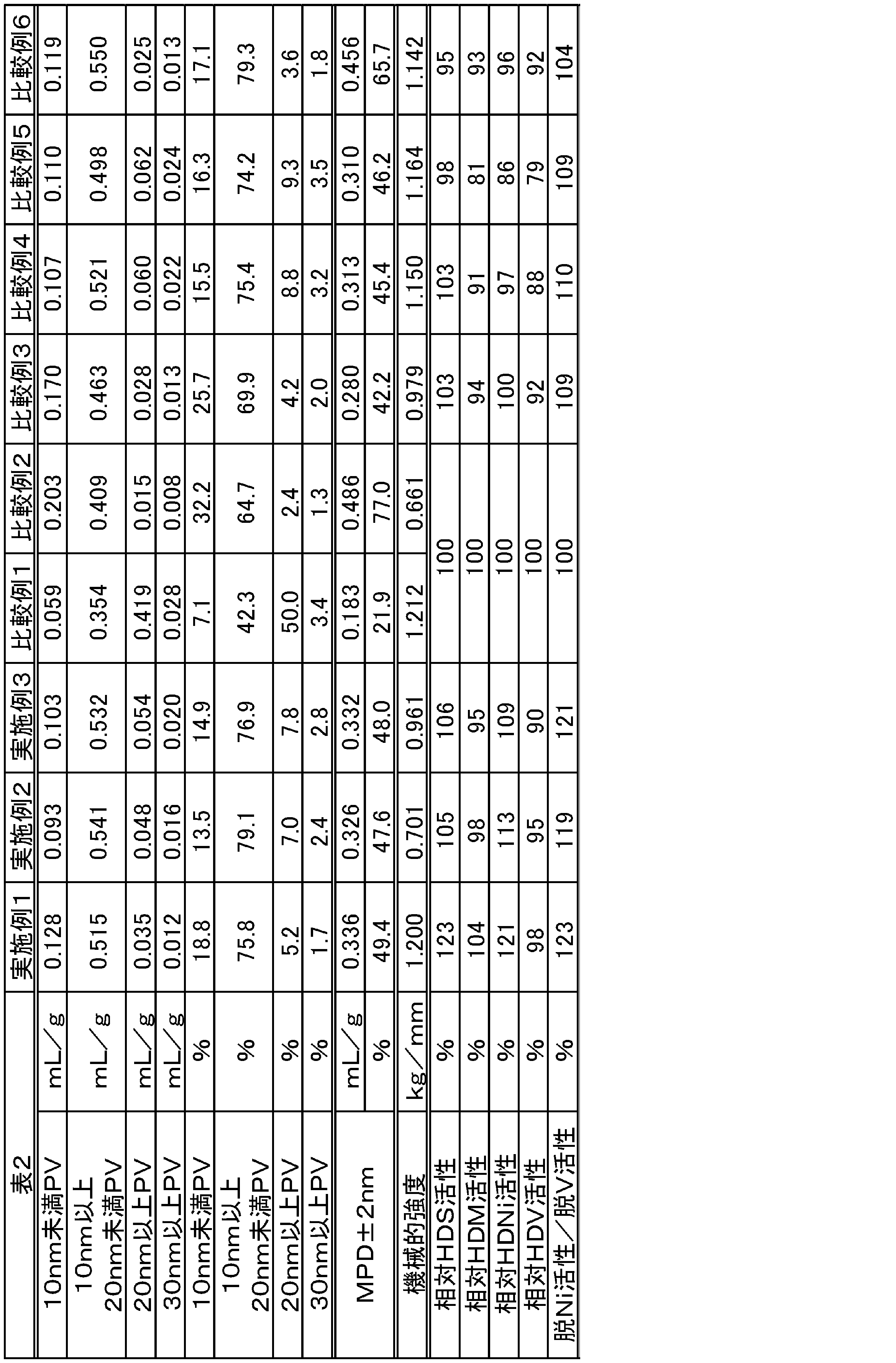
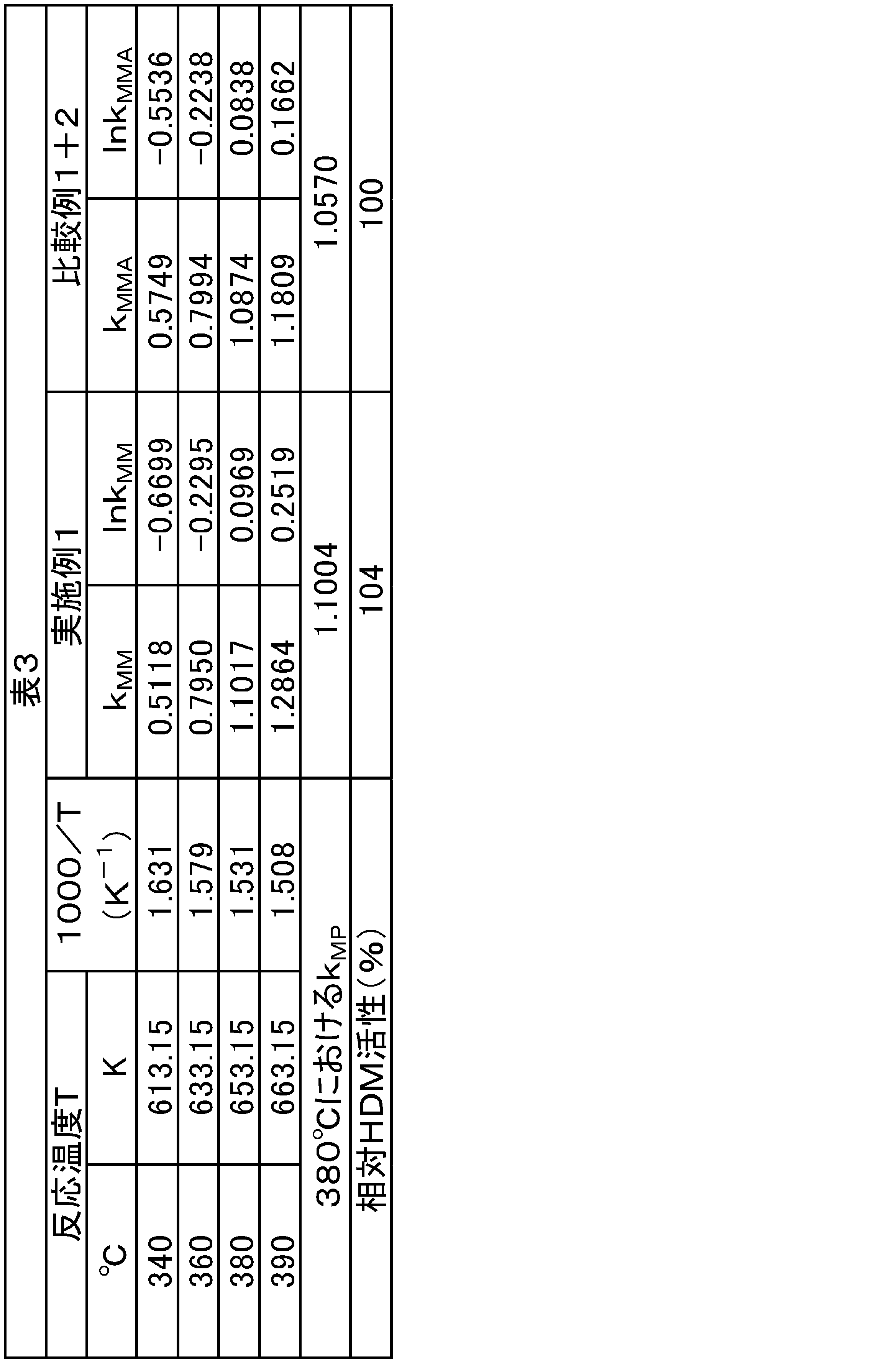
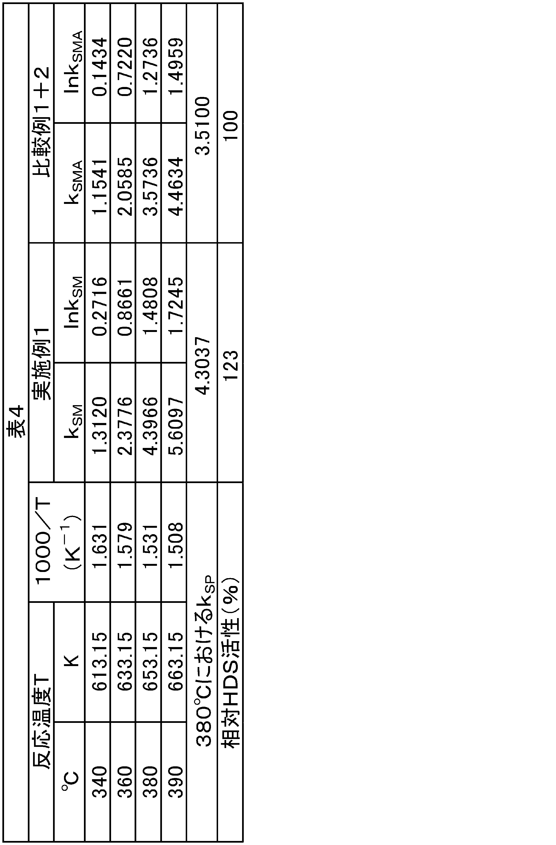
表2に示すように、実施例1~3の脱メタル触媒は、比較例1~6の脱メタル触媒に比べて、脱メタル活性及び脱硫活性に優れることが確認された。
本発明に係る炭化水素油の製造方法は、重質燃料油、軽油、灯油、ナフサ、ガソリン、潤滑油用基油、その他化学品原料等の製造に適している。
Claims (6)
- 原料油を水素ガスの存在下で触媒に接触させることにより、前記原料油中の硫黄分及び金属分を除去する工程を備え、
前記触媒は、
多孔質の担体と、
前記担体に担持されている第1活性金属と、
前記担体に担持されている第2活性金属と、
を有し、
前記触媒に形成されている全細孔のうち、細孔直径が2nm以上12nm未満である細孔の容積の合計が、0.15mL/g以上0.28mL/g以下であり、
前記触媒に形成されている全細孔のうち、細孔直径が12nm以上16nm未満である細孔の容積の合計が、0.28mL/g以上0.45mL/g以下であり、
前記第1活性金属が、クロム、モリブデン及びタングステンからなる群より選ばれる少なくとも一種の金属であり、
前記第2活性金属が、コバルト、ロジウム、イリジウム、ニッケル、パラジウム及び白金からなる群より選ばれる少なくとも二種の金属である、
炭化水素油の製造方法。 - 前記第1活性金属が、モリブデンであり、
前記第2活性金属が、コバルト及びニッケルである、
請求項1に記載の炭化水素油の製造方法。 - 前記触媒におけるリンの含有量が、前記触媒の全質量を基準として、元素換算で、0.1質量%未満である、
請求項1又は2に記載の炭化水素油の製造方法。 - 前記触媒における脱ニッケル活性が、前記触媒における脱バナジウム活性よりも高い、
請求項1~3のいずれか一項に記載の炭化水素油の製造方法。 - 前記触媒の比表面積が、180~230m2/gである、
請求項1~4のいずれか一項に記載の炭化水素油の製造方法。 - 前記触媒の全細孔の容積の合計が、0.60mL/g以上である、
請求項1~5のいずれか一項に記載の炭化水素油の製造方法。
Applications Claiming Priority (2)
| Application Number | Priority Date | Filing Date | Title |
|---|---|---|---|
| JP2018-014496 | 2018-01-31 | ||
| JP2018014496A JP7011479B2 (ja) | 2018-01-31 | 2018-01-31 | 炭化水素油の製造方法 |
Publications (1)
| Publication Number | Publication Date |
|---|---|
| WO2019150647A1 true WO2019150647A1 (ja) | 2019-08-08 |
Family
ID=67478190
Family Applications (1)
| Application Number | Title | Priority Date | Filing Date |
|---|---|---|---|
| PCT/JP2018/035149 Ceased WO2019150647A1 (ja) | 2018-01-31 | 2018-09-21 | 炭化水素油の製造方法 |
Country Status (2)
| Country | Link |
|---|---|
| JP (1) | JP7011479B2 (ja) |
| WO (1) | WO2019150647A1 (ja) |
Citations (5)
| Publication number | Priority date | Publication date | Assignee | Title |
|---|---|---|---|---|
| JPS59132945A (ja) * | 1983-01-21 | 1984-07-31 | Shokubai Kasei Kogyo Kk | 重質炭化水素油の水素化処理方法 |
| JPH06154610A (ja) * | 1992-11-27 | 1994-06-03 | Chevron Res & Technol Co | 高いメタル含有量を有する残油用の触媒、その製造法及び使用プロセス |
| CN101618326A (zh) * | 2008-06-30 | 2010-01-06 | 中国石油化工股份有限公司 | 一种重油加氢处理催化剂及其制备方法 |
| CN102397790A (zh) * | 2010-09-09 | 2012-04-04 | 中国石油化工股份有限公司 | 一种重油加氢处理催化剂、制备及其应用 |
| JP2015519193A (ja) * | 2012-04-26 | 2015-07-09 | シエル・インターナシヨナル・リサーチ・マートスハツペイ・ベー・ヴエー | 水素化処理触媒および重質炭化水素供給原料を処理するための方法 |
Family Cites Families (7)
| Publication number | Priority date | Publication date | Assignee | Title |
|---|---|---|---|---|
| US20050109674A1 (en) | 2003-11-20 | 2005-05-26 | Advanced Refining Technologies Llc | Hydroconversion catalysts and methods of making and using same |
| JP4902424B2 (ja) | 2007-05-21 | 2012-03-21 | Jx日鉱日石エネルギー株式会社 | 水素化精製触媒及び水素化精製方法 |
| US8173570B2 (en) | 2007-10-31 | 2012-05-08 | Chevron U.S.A. Inc. | Hydroconversion processes employing multi-metallic catalysts and method for making thereof |
| RU2624024C2 (ru) | 2011-09-01 | 2017-06-30 | Адванст Рифайнинг Текнолоджиз Ллк | Носитель катализатора и катализаторы, полученные на его основе |
| MX352582B (es) | 2012-11-06 | 2017-11-07 | Mexicano Inst Petrol | Composito mesoporoso de mallas moleculares para la hidrodesintegracion de crudos pesados y residuos. |
| WO2015046323A1 (ja) | 2013-09-27 | 2015-04-02 | コスモ石油株式会社 | 重質炭化水素油の水素化処理触媒、及び重質炭化水素油の水素化処理方法 |
| JP7269247B2 (ja) | 2018-01-31 | 2023-05-08 | アドバンスド・リフアイニング・テクノロジーズ・エルエルシー | 重油中の金属及び硫黄の削減のための水素化処理触媒 |
-
2018
- 2018-01-31 JP JP2018014496A patent/JP7011479B2/ja active Active
- 2018-09-21 WO PCT/JP2018/035149 patent/WO2019150647A1/ja not_active Ceased
Patent Citations (5)
| Publication number | Priority date | Publication date | Assignee | Title |
|---|---|---|---|---|
| JPS59132945A (ja) * | 1983-01-21 | 1984-07-31 | Shokubai Kasei Kogyo Kk | 重質炭化水素油の水素化処理方法 |
| JPH06154610A (ja) * | 1992-11-27 | 1994-06-03 | Chevron Res & Technol Co | 高いメタル含有量を有する残油用の触媒、その製造法及び使用プロセス |
| CN101618326A (zh) * | 2008-06-30 | 2010-01-06 | 中国石油化工股份有限公司 | 一种重油加氢处理催化剂及其制备方法 |
| CN102397790A (zh) * | 2010-09-09 | 2012-04-04 | 中国石油化工股份有限公司 | 一种重油加氢处理催化剂、制备及其应用 |
| JP2015519193A (ja) * | 2012-04-26 | 2015-07-09 | シエル・インターナシヨナル・リサーチ・マートスハツペイ・ベー・ヴエー | 水素化処理触媒および重質炭化水素供給原料を処理するための方法 |
Also Published As
| Publication number | Publication date |
|---|---|
| JP7011479B2 (ja) | 2022-01-26 |
| JP2019131688A (ja) | 2019-08-08 |
Similar Documents
| Publication | Publication Date | Title |
|---|---|---|
| JP4472556B2 (ja) | 炭化水素油の水素化処理触媒及びその製造方法並びに炭化水素油の水素化処理方法 | |
| US10406509B2 (en) | Nanoscale nickel phosphide catalysts for hydrotreatment | |
| JP4156859B2 (ja) | 軽油の水素化処理触媒及びその製造方法並びに軽油の水素化処理方法 | |
| US4048060A (en) | Two-stage hydrodesulfurization of oil utilizing a narrow pore size distribution catalyst | |
| JP6506430B2 (ja) | チタニアを含有する改良された残油水素化処理触媒 | |
| ES2890477T3 (es) | Hidroprocesamiento de hidrocarburos con el uso de una mezcla de catalizadores | |
| GB1580854A (en) | Catalyst and process for the hydro-desulphurisation of hydrocarbon feeds | |
| KR20050085710A (ko) | 경유의 수소화 처리 촉매, 이의 제조방법 및 경유의 수소화처리방법 | |
| KR102277831B1 (ko) | 수소화처리 촉매의 제조 방법 | |
| JP2000000470A (ja) | 水素化処理触媒及び重質油の水素化処理方法 | |
| JP4864106B2 (ja) | 炭化水素油の水素化処理触媒の製造方法 | |
| EP0759964B1 (en) | Stacked bed catalyst system for deep hydrosulfurization | |
| CA2686745A1 (en) | Hydrodesulphurization nanocatalyst, its use and a process for its production | |
| JP2010248476A (ja) | 重質炭化水素油の水素化処理方法 | |
| US11318448B2 (en) | Hydroprocessing catalyst for the reduction of metals and sulfur in heavy feeds | |
| JP2002239385A (ja) | 炭化水素油用水素化処理触媒の製造方法及び炭化水素油の水素化処理方法 | |
| JP4689198B2 (ja) | 炭化水素油の水素化処理触媒及びその製造方法、並びに炭化水素油の水素化処理方法 | |
| JP4680520B2 (ja) | 低硫黄軽油の製造方法および環境対応軽油 | |
| WO2019150647A1 (ja) | 炭化水素油の製造方法 | |
| JP4954095B2 (ja) | 軽油の水素化処理触媒及びその製造方法並びに軽油の水素化処理方法 | |
| JP2005314657A (ja) | 重質炭化水素油の水素化処理方法 | |
| JP5660672B2 (ja) | 炭化水素油の水素化処理触媒の再生方法 | |
| JP2004290728A (ja) | 軽油の水素化処理触媒の製造方法及び軽油の水素化処理方法 | |
| GB1584706A (en) | Hydrotreating catalyst and process utilizing the same | |
| JP2006306974A (ja) | 炭化水素油の水素化処理触媒及びその製造方法並びに炭化水素油の水素化処理方法 |
Legal Events
| Date | Code | Title | Description |
|---|---|---|---|
| 121 | Ep: the epo has been informed by wipo that ep was designated in this application |
Ref document number: 18903193 Country of ref document: EP Kind code of ref document: A1 |
|
| NENP | Non-entry into the national phase |
Ref country code: DE |
|
| 122 | Ep: pct application non-entry in european phase |
Ref document number: 18903193 Country of ref document: EP Kind code of ref document: A1 |