WO2019146799A2 - 有機物分解処理用イオン生成装置及び有機物分解処理装置 - Google Patents
有機物分解処理用イオン生成装置及び有機物分解処理装置 Download PDFInfo
- Publication number
- WO2019146799A2 WO2019146799A2 PCT/JP2019/002989 JP2019002989W WO2019146799A2 WO 2019146799 A2 WO2019146799 A2 WO 2019146799A2 JP 2019002989 W JP2019002989 W JP 2019002989W WO 2019146799 A2 WO2019146799 A2 WO 2019146799A2
- Authority
- WO
- WIPO (PCT)
- Prior art keywords
- electrode
- ion
- organic matter
- organic substance
- flat plate
- Prior art date
Links
- 238000000354 decomposition reaction Methods 0.000 title claims abstract description 65
- 239000005416 organic matter Substances 0.000 title claims abstract description 36
- 150000002500 ions Chemical class 0.000 claims description 77
- 239000000126 substance Substances 0.000 claims description 42
- 238000012545 processing Methods 0.000 claims description 34
- 238000003860 storage Methods 0.000 claims description 22
- 239000011796 hollow space material Substances 0.000 claims description 18
- 238000007599 discharging Methods 0.000 claims 1
- -1 hydroxy radicals Chemical class 0.000 description 63
- XLYOFNOQVPJJNP-UHFFFAOYSA-N water Substances O XLYOFNOQVPJJNP-UHFFFAOYSA-N 0.000 description 31
- 239000007789 gas Substances 0.000 description 21
- 229920000642 polymer Polymers 0.000 description 19
- 238000001704 evaporation Methods 0.000 description 17
- 230000008020 evaporation Effects 0.000 description 17
- CBENFWSGALASAD-UHFFFAOYSA-N Ozone Chemical compound [O-][O+]=O CBENFWSGALASAD-UHFFFAOYSA-N 0.000 description 16
- XEEYBQQBJWHFJM-UHFFFAOYSA-N Iron Chemical compound [Fe] XEEYBQQBJWHFJM-UHFFFAOYSA-N 0.000 description 12
- 230000002745 absorbent Effects 0.000 description 12
- 239000002250 absorbent Substances 0.000 description 12
- 230000000052 comparative effect Effects 0.000 description 12
- 238000009834 vaporization Methods 0.000 description 12
- 230000008016 vaporization Effects 0.000 description 12
- 238000005259 measurement Methods 0.000 description 11
- 230000005684 electric field Effects 0.000 description 10
- 239000001257 hydrogen Substances 0.000 description 9
- 229910052739 hydrogen Inorganic materials 0.000 description 9
- 230000001590 oxidative effect Effects 0.000 description 9
- 239000006096 absorbing agent Substances 0.000 description 7
- 125000004429 atom Chemical group 0.000 description 6
- QVGXLLKOCUKJST-UHFFFAOYSA-N atomic oxygen Chemical compound [O] QVGXLLKOCUKJST-UHFFFAOYSA-N 0.000 description 6
- 229910052742 iron Inorganic materials 0.000 description 6
- 239000001301 oxygen Substances 0.000 description 6
- 229910052760 oxygen Inorganic materials 0.000 description 6
- 238000012360 testing method Methods 0.000 description 6
- 238000012795 verification Methods 0.000 description 6
- 150000001768 cations Chemical class 0.000 description 5
- 238000006243 chemical reaction Methods 0.000 description 5
- 239000000460 chlorine Substances 0.000 description 5
- 239000010794 food waste Substances 0.000 description 5
- XLYOFNOQVPJJNP-UHFFFAOYSA-O oxonium Chemical compound [OH3+] XLYOFNOQVPJJNP-UHFFFAOYSA-O 0.000 description 5
- IJGRMHOSHXDMSA-UHFFFAOYSA-N Atomic nitrogen Chemical compound N#N IJGRMHOSHXDMSA-UHFFFAOYSA-N 0.000 description 4
- ZAMOUSCENKQFHK-UHFFFAOYSA-N Chlorine atom Chemical compound [Cl] ZAMOUSCENKQFHK-UHFFFAOYSA-N 0.000 description 4
- 229910052801 chlorine Inorganic materials 0.000 description 4
- 238000000034 method Methods 0.000 description 4
- 239000010813 municipal solid waste Substances 0.000 description 4
- 239000000047 product Substances 0.000 description 4
- PXGOKWXKJXAPGV-UHFFFAOYSA-N Fluorine Chemical compound FF PXGOKWXKJXAPGV-UHFFFAOYSA-N 0.000 description 3
- UFHFLCQGNIYNRP-UHFFFAOYSA-N Hydrogen Chemical compound [H][H] UFHFLCQGNIYNRP-UHFFFAOYSA-N 0.000 description 3
- 238000009835 boiling Methods 0.000 description 3
- 125000004122 cyclic group Chemical group 0.000 description 3
- 230000007423 decrease Effects 0.000 description 3
- 238000009826 distribution Methods 0.000 description 3
- 238000001035 drying Methods 0.000 description 3
- 229910052731 fluorine Inorganic materials 0.000 description 3
- 239000011737 fluorine Substances 0.000 description 3
- 239000003574 free electron Substances 0.000 description 3
- 238000010438 heat treatment Methods 0.000 description 3
- 230000001678 irradiating effect Effects 0.000 description 3
- 238000007254 oxidation reaction Methods 0.000 description 3
- 238000003756 stirring Methods 0.000 description 3
- RTZKZFJDLAIYFH-UHFFFAOYSA-N Diethyl ether Chemical compound CCOCC RTZKZFJDLAIYFH-UHFFFAOYSA-N 0.000 description 2
- LFQSCWFLJHTTHZ-UHFFFAOYSA-N Ethanol Chemical compound CCO LFQSCWFLJHTTHZ-UHFFFAOYSA-N 0.000 description 2
- 238000004364 calculation method Methods 0.000 description 2
- 150000001793 charged compounds Chemical class 0.000 description 2
- 238000011161 development Methods 0.000 description 2
- 230000000694 effects Effects 0.000 description 2
- 239000000463 material Substances 0.000 description 2
- 239000007769 metal material Substances 0.000 description 2
- VNWKTOKETHGBQD-UHFFFAOYSA-N methane Chemical compound C VNWKTOKETHGBQD-UHFFFAOYSA-N 0.000 description 2
- 229910052757 nitrogen Inorganic materials 0.000 description 2
- 229920000915 polyvinyl chloride Polymers 0.000 description 2
- 239000004800 polyvinyl chloride Substances 0.000 description 2
- 239000003642 reactive oxygen metabolite Substances 0.000 description 2
- 229910001220 stainless steel Inorganic materials 0.000 description 2
- 239000010935 stainless steel Substances 0.000 description 2
- WFKWXMTUELFFGS-UHFFFAOYSA-N tungsten Chemical compound [W] WFKWXMTUELFFGS-UHFFFAOYSA-N 0.000 description 2
- 229910052721 tungsten Inorganic materials 0.000 description 2
- 239000010937 tungsten Substances 0.000 description 2
- 235000013311 vegetables Nutrition 0.000 description 2
- 239000002699 waste material Substances 0.000 description 2
- 241000894006 Bacteria Species 0.000 description 1
- MHAJPDPJQMAIIY-UHFFFAOYSA-N Hydrogen peroxide Chemical compound OO MHAJPDPJQMAIIY-UHFFFAOYSA-N 0.000 description 1
- BQCADISMDOOEFD-UHFFFAOYSA-N Silver Chemical compound [Ag] BQCADISMDOOEFD-UHFFFAOYSA-N 0.000 description 1
- OUUQCZGPVNCOIJ-UHFFFAOYSA-M Superoxide Chemical compound [O-][O] OUUQCZGPVNCOIJ-UHFFFAOYSA-M 0.000 description 1
- 238000000367 ab initio method Methods 0.000 description 1
- 238000004458 analytical method Methods 0.000 description 1
- 150000001450 anions Chemical class 0.000 description 1
- 238000013459 approach Methods 0.000 description 1
- 230000015572 biosynthetic process Effects 0.000 description 1
- 239000006227 byproduct Substances 0.000 description 1
- 230000003247 decreasing effect Effects 0.000 description 1
- 238000004836 empirical method Methods 0.000 description 1
- 238000002474 experimental method Methods 0.000 description 1
- 229910052736 halogen Inorganic materials 0.000 description 1
- 150000002367 halogens Chemical class 0.000 description 1
- GPRLSGONYQIRFK-UHFFFAOYSA-N hydron Chemical compound [H+] GPRLSGONYQIRFK-UHFFFAOYSA-N 0.000 description 1
- 239000011810 insulating material Substances 0.000 description 1
- 230000010354 integration Effects 0.000 description 1
- JEIPFZHSYJVQDO-UHFFFAOYSA-N iron(III) oxide Inorganic materials O=[Fe]O[Fe]=O JEIPFZHSYJVQDO-UHFFFAOYSA-N 0.000 description 1
- 238000012423 maintenance Methods 0.000 description 1
- 238000004519 manufacturing process Methods 0.000 description 1
- 230000007935 neutral effect Effects 0.000 description 1
- 229910052756 noble gas Inorganic materials 0.000 description 1
- 239000010815 organic waste Substances 0.000 description 1
- YQBOZXASCNTXGC-UHFFFAOYSA-N oxatriquinacene Chemical compound C1=CC2C=CC3[O+]2C1C=C3 YQBOZXASCNTXGC-UHFFFAOYSA-N 0.000 description 1
- 230000003647 oxidation Effects 0.000 description 1
- 125000004430 oxygen atom Chemical group O* 0.000 description 1
- 150000003254 radicals Chemical class 0.000 description 1
- 238000000926 separation method Methods 0.000 description 1
- 238000004904 shortening Methods 0.000 description 1
- 229910052709 silver Inorganic materials 0.000 description 1
- 239000004332 silver Substances 0.000 description 1
- 241000894007 species Species 0.000 description 1
Images


Classifications
-
- H—ELECTRICITY
- H01—ELECTRIC ELEMENTS
- H01T—SPARK GAPS; OVERVOLTAGE ARRESTERS USING SPARK GAPS; SPARKING PLUGS; CORONA DEVICES; GENERATING IONS TO BE INTRODUCED INTO NON-ENCLOSED GASES
- H01T19/00—Devices providing for corona discharge
- H01T19/04—Devices providing for corona discharge having pointed electrodes
-
- A—HUMAN NECESSITIES
- A61—MEDICAL OR VETERINARY SCIENCE; HYGIENE
- A61L—METHODS OR APPARATUS FOR STERILISING MATERIALS OR OBJECTS IN GENERAL; DISINFECTION, STERILISATION OR DEODORISATION OF AIR; CHEMICAL ASPECTS OF BANDAGES, DRESSINGS, ABSORBENT PADS OR SURGICAL ARTICLES; MATERIALS FOR BANDAGES, DRESSINGS, ABSORBENT PADS OR SURGICAL ARTICLES
- A61L2/00—Methods or apparatus for disinfecting or sterilising materials or objects other than foodstuffs or contact lenses; Accessories therefor
- A61L2/02—Methods or apparatus for disinfecting or sterilising materials or objects other than foodstuffs or contact lenses; Accessories therefor using physical phenomena
-
- A—HUMAN NECESSITIES
- A61—MEDICAL OR VETERINARY SCIENCE; HYGIENE
- A61L—METHODS OR APPARATUS FOR STERILISING MATERIALS OR OBJECTS IN GENERAL; DISINFECTION, STERILISATION OR DEODORISATION OF AIR; CHEMICAL ASPECTS OF BANDAGES, DRESSINGS, ABSORBENT PADS OR SURGICAL ARTICLES; MATERIALS FOR BANDAGES, DRESSINGS, ABSORBENT PADS OR SURGICAL ARTICLES
- A61L9/00—Disinfection, sterilisation or deodorisation of air
- A61L9/16—Disinfection, sterilisation or deodorisation of air using physical phenomena
- A61L9/22—Ionisation
-
- B—PERFORMING OPERATIONS; TRANSPORTING
- B09—DISPOSAL OF SOLID WASTE; RECLAMATION OF CONTAMINATED SOIL
- B09B—DISPOSAL OF SOLID WASTE NOT OTHERWISE PROVIDED FOR
- B09B3/00—Destroying solid waste or transforming solid waste into something useful or harmless
-
- A—HUMAN NECESSITIES
- A61—MEDICAL OR VETERINARY SCIENCE; HYGIENE
- A61L—METHODS OR APPARATUS FOR STERILISING MATERIALS OR OBJECTS IN GENERAL; DISINFECTION, STERILISATION OR DEODORISATION OF AIR; CHEMICAL ASPECTS OF BANDAGES, DRESSINGS, ABSORBENT PADS OR SURGICAL ARTICLES; MATERIALS FOR BANDAGES, DRESSINGS, ABSORBENT PADS OR SURGICAL ARTICLES
- A61L11/00—Methods specially adapted for refuse
-
- H—ELECTRICITY
- H01—ELECTRIC ELEMENTS
- H01T—SPARK GAPS; OVERVOLTAGE ARRESTERS USING SPARK GAPS; SPARKING PLUGS; CORONA DEVICES; GENERATING IONS TO BE INTRODUCED INTO NON-ENCLOSED GASES
- H01T19/00—Devices providing for corona discharge
-
- H—ELECTRICITY
- H01—ELECTRIC ELEMENTS
- H01T—SPARK GAPS; OVERVOLTAGE ARRESTERS USING SPARK GAPS; SPARKING PLUGS; CORONA DEVICES; GENERATING IONS TO BE INTRODUCED INTO NON-ENCLOSED GASES
- H01T19/00—Devices providing for corona discharge
- H01T19/02—Corona rings
-
- H—ELECTRICITY
- H01—ELECTRIC ELEMENTS
- H01T—SPARK GAPS; OVERVOLTAGE ARRESTERS USING SPARK GAPS; SPARKING PLUGS; CORONA DEVICES; GENERATING IONS TO BE INTRODUCED INTO NON-ENCLOSED GASES
- H01T23/00—Apparatus for generating ions to be introduced into non-enclosed gases, e.g. into the atmosphere
-
- Y—GENERAL TAGGING OF NEW TECHNOLOGICAL DEVELOPMENTS; GENERAL TAGGING OF CROSS-SECTIONAL TECHNOLOGIES SPANNING OVER SEVERAL SECTIONS OF THE IPC; TECHNICAL SUBJECTS COVERED BY FORMER USPC CROSS-REFERENCE ART COLLECTIONS [XRACs] AND DIGESTS
- Y02—TECHNOLOGIES OR APPLICATIONS FOR MITIGATION OR ADAPTATION AGAINST CLIMATE CHANGE
- Y02E—REDUCTION OF GREENHOUSE GAS [GHG] EMISSIONS, RELATED TO ENERGY GENERATION, TRANSMISSION OR DISTRIBUTION
- Y02E50/00—Technologies for the production of fuel of non-fossil origin
- Y02E50/30—Fuel from waste, e.g. synthetic alcohol or diesel
-
- Y—GENERAL TAGGING OF NEW TECHNOLOGICAL DEVELOPMENTS; GENERAL TAGGING OF CROSS-SECTIONAL TECHNOLOGIES SPANNING OVER SEVERAL SECTIONS OF THE IPC; TECHNICAL SUBJECTS COVERED BY FORMER USPC CROSS-REFERENCE ART COLLECTIONS [XRACs] AND DIGESTS
- Y02—TECHNOLOGIES OR APPLICATIONS FOR MITIGATION OR ADAPTATION AGAINST CLIMATE CHANGE
- Y02W—CLIMATE CHANGE MITIGATION TECHNOLOGIES RELATED TO WASTEWATER TREATMENT OR WASTE MANAGEMENT
- Y02W30/00—Technologies for solid waste management
- Y02W30/20—Waste processing or separation
Definitions
- the present invention relates to an ion generation apparatus for organic substance decomposition treatment and an organic substance decomposition treatment apparatus, and is suitably applied to an organic substance decomposition treatment apparatus for decomposition treatment of food waste such as vegetable waste, for example.
- Patent Document 1 A garbage processing apparatus is conventionally known that uses active oxygen species when decomposing organic substances such as garbage (see, for example, Patent Document 1).
- Patent Document 1 for example, as active oxygen species, superoxide (O 2 ⁇ -), or hydroxy radicals ( ⁇ OH), hydrogen peroxide (H 2 O 2), unification oxygen (1 O 2), ozone It is disclosed that the organic waste introduced into the storage tank is decomposed using (O 3 ) or the like.
- Such garbage disposal equipment using reactive oxygen species has the advantage of being less likely to generate methane gas during decomposition processing and capable of suppressing putrefaction odor, etc., compared to garbage disposal equipment using bacteria. .
- this invention aims at providing the ion production
- An ion generation apparatus for organic substance decomposition processing is an ion generation apparatus for organic substance decomposition processing that generates ions for decomposition processing of organic substances stored in a storage tank, and a needle electrode and a flat plate disposed oppositely An electrode and a DC power supply unit for applying a positive DC voltage to the needle electrode, wherein the DC power supply unit sets the DC voltage to a predetermined voltage value, and A voltage control unit for generating positive polarity corona discharge is provided between the flat plate electrodes.
- the organic substance decomposition processing apparatus is provided with the above-mentioned ion generation apparatus for organic substance decomposition processing in the storage tank.
- the decomposition processing ability of an organic substance can be further improved as compared with the conventional one.
- FIG. 2A is a schematic view showing the configuration of the electrode structure
- FIG. 2B is a schematic view showing the front configuration of the electrode structure.
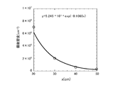
- It is a graph which is provided to the explanation of electron affinity. It is a graph for use in describing the relationship between the evaporation rate v and the heat of vaporization L V. It is the graph which showed the number density of the oxonium ion in the position away from the generation position of the oxonium ion by the distance x.
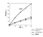
- the evaporation mass of the contained polymer absorber was measured for each of the cases of irradiation with oxonium ion, irradiation with negative ion and ozone, irradiation with only negative ion, and irradiation with no ion etc. It is a graph which shows the measured result.
- the residual mass of the contained polymer absorber was measured for each of the cases of irradiation with oxonium ions, irradiation with negative ions and ozone, irradiation with only negative ions, and irradiation with no ions etc. It is a graph which shows the measured result.
- FIG. 1 is a schematic view showing an entire configuration of the organic matter decomposition treatment apparatus 1 according to the present invention.
- the organic matter decomposition processing apparatus 1 has a configuration that can decompose various organic substances such as a polymer body and a paper material as well as food waste such as vegetable waste using oxonium ions.
- the oxonium ion is, for example, a hydronium ion, oxatriquinan, oxatriquinacene or the like, and is a positive ion.
- the organic substance decomposition treatment apparatus 1 includes a storage tank 2 into which an organic substance is charged, a blower 3 and an ion generation apparatus 4 for organic substance decomposition treatment.
- the organic substance to be decomposed is introduced into the storage tank 2 from the inlet 2 a and stored in the storage tank 2.
- the decomposed organic matter can be discharged to the outside from the discharge port 2 b of the storage tank 2.
- the organic matter decomposition treatment apparatus 1 is internally provided with a heater and a stirrer (not shown), and the organic matter in the storage tank 2 is irradiated with the oxonium ions generated by the organic matter decomposition treatment ion generator 4
- the moisture of the organic matter is evaporated and decomposed by heating and stirring the organic matter.
- the blower 3 and the organic substance decomposition treatment ion generation device 4 are respectively installed at predetermined positions of the storage tank 2, and the blower 3 and the organic matter decomposition treatment ion generation device 4 are connected by a pipe 5.
- the blower 3 sucks the outside air, and sends the sucked gas to the ion generating apparatus 4 for organic substance decomposition treatment via the pipe 5.
- the gas delivered from the blower 3 into the organic matter decomposition processing ion generator 4 passes through the inside of the organic matter decomposition processing ion generator 4 and is delivered into the storage tank 2.
- the organic substance decomposition treatment ion generation device 4 includes a housing 8 in which an electrode structure to be described later is installed, and a DC power supply unit 9.
- the housing 8 is provided with an inlet (not shown) which is connected to the pipe 5 and introduces the gas discharged from the blower 3 into the housing 8. Further, the housing 8 is provided with a discharge port (not shown) which communicates with the storage tank 2 and discharges the gas from the blower 3 into the storage tank 2.
- the housing 8 forms a sealed space inside, and the gas from the blower 3 is introduced into the sealed space, so that it is directed from the introduction port to the discharge port via the electrode structure (described later). It forms a gas flow. Thereby, the housing
- the DC power supply unit 9 generates a DC voltage of positive polarity and applies this to the electrode structure in the housing 8.
- the DC power supply unit 9 has a voltage control unit 10 capable of controlling the voltage value of the DC voltage, and the voltage control unit 10 sets the DC voltage to a predetermined voltage value. Thereby, the voltage control unit 10 can generate positive polarity corona discharge in the electrode structure and generate oxonium ions in the electrode structure. At this time, the voltage control unit 10 sets the voltage value of the direct current voltage to an optimal value in order to generate oxonium ions having high decomposition processing ability of the organic matter.
- the electrode structure 11 includes a needle electrode 12, a flat electrode 13, and an electrode support member 14.
- the electrode support member 14 is made of, for example, an insulating material such as polyvinyl chloride, is formed in a cylindrical shape, and supports the needle electrode 12 and the flat plate electrode 13.
- cylindrical electrode support member 14 is applied as the cylindrical electrode support member
- the present invention is not limited thereto.
- a rectangular cylindrical shape such as four sides or a polygon
- the electrode support member may be applied.
- the electrode support member 14 supports the needle electrode 12 and the flat plate electrode 13 so as to be opposed to each other in the hollow space ER1 surrounded by the cylindrical inner wall portion 14a.
- the electrode support member 14 is disposed between an inlet and an outlet (not shown) of the housing 8 (FIG. 1). Thereby, when the gas from the blower 3 is introduced into the housing 8 from the inlet, an air flow flowing in one direction (for example, the arrow direction of the central axis X) along the central axis X in the hollow space ER1 is It is formed in the hollow space ER1.
- the electrode support member 14 be disposed in the housing 8 such that the inlet and the outlet of the housing 8 are disposed on the central axis X of the hollow space ER1.
- an air flow can be formed that linearly connects the discharge port from the hollow space ER1.
- the oxonium ions (described later) generated in the hollow space ER1 can be prevented from impinging on the inner wall or the like of the housing 8, and the oxonium ions can be directly led to the discharge port.
- Electrode support member 14 as shown in FIG. 2B, for example, the internal diameter Y 2 between the cylindrical inner wall portion 14a is 25 ⁇ 5 mm, external diameter Y 3 is selected to be 32 ⁇ 5 mm.
- the needle electrode 12 and the flat plate electrode 13 are disposed opposite to each other on one orthogonal line Y orthogonal to the central axis X of the hollow space ER1, as shown in FIG. 2B.
- the flat plate portion 13 b of the flat plate electrode 13 is disposed immediately below.
- the needle electrode 12 is made of, for example, a metal material such as tungsten and is selected to have a diameter of 0.1 to 2 mm.
- the needle electrode 12 is provided so as to penetrate the cylindrical inner wall portion 14a of the electrode support member 14, and the needle-like tip 12a is exposed in the hollow space ER1.
- the flat plate electrode 13 is made of, for example, a metal material such as stainless steel, and includes a support portion 13a formed in a bar shape and a flat portion 13b formed at an end of the support portion 13a.
- the flat plate portion 13b is formed in a disk shape having a diameter of 5 to 20 mm and a thickness of 1.5 ⁇ 1 mm.
- the support portion 13a is provided so as to penetrate the cylindrical inner wall portion 14a of the electrode support member 14, and exposes the flat plate portion 13b in the hollow space ER1.
- the needle electrode 12 and the support portion 13a of the flat plate electrode 13 are provided to penetrate the cylindrical inner wall portion 14a.
- the present invention is not limited to this.
- the tip end of the root portion of the needle electrode 12 may be fixed to the surface of the cylindrical inner wall portion 14a, and the needle electrode 12 may be provided non-penetratingly to the cylindrical inner wall portion 14a.
- the support portion 13a or the flat plate portion 13b may be fixed to the surface of the cylindrical inner wall portion 14a, and may be provided so as not to penetrate the cylindrical inner wall portion 14a.
- a needle tip 12a of the needle electrode 12, the distance between the electrodes Y 1 between the flat plate portion 13b of the flat plate electrode 13 facing the needle tip 12a is selected for example to 20 mm.
- the distance between the electrodes Y 1 is not limited to 20 mm, the voltage value of the positive DC voltage to be described later (kV), it is basically defined out with the electric field strength (kV / mm).
- the root portion of the needle electrode 12 exposed to the outside of the electrode support member 14 is connected to the voltage control unit 10.
- the flat plate electrode 13 is connected to the ground.
- the flat plate electrode 13 may be connected to the voltage control unit 10 without being connected to the ground, and a negative DC voltage may be applied to function as a negative electrode.
- the electric field strength is 0.25 to 1.5 kV / mm and the voltage value is 5 as the positive DC voltage applied to the needle electrode 12 by the voltage control unit 10. It is desirable to be ⁇ 30kV.
- the electric field intensity of the DC voltage of positive polarity and 0.25 ⁇ 1.5kV / mm a positive polarity corona discharge in the inter-electrode distance Y 1 can be generated stably.
- one of the main reactions for generating ions in the discharge space is a reaction for generating molecular ions.
- the gas molecule M In order for the gas molecule M to be ionized and split into molecular ions M + and electrons e ⁇ , it is necessary to give the gas molecule M an energy higher than the ionization energy of the gas molecule M. In the discharge space under atmospheric pressure, this energy is provided by the collision of electrons accelerated in the high field glow region.
- the primary ions generated by the discharge travel in the electric field along the electric field lines according to their own polarity.
- the primary ions traveling toward the flat plate electrode 13 collide with the gas existing in the discharge space and the discharge by-products derived from the neutral radical species A ⁇ , [M ⁇ B], and B ⁇ when going through the mean free path. It causes various ion molecule reactions and changes to longer-lived ion species. This process continues as it travels through the drift region and, through sequential ion molecule reactions, the final ion is generated.
- the oxonium ion is the final ion regardless of the discharge conditions.
- the formation of oxonium ion in positive polarity corona discharge in the atmosphere and its development process are predicted based on the measured values of the rate constant of each elementary reaction.
- hydronium ions have a development process mainly involving H 2 O , with N 2 + ⁇ and O 2 + ⁇ generated by ionization in the glow region as primary ions. Generated through.
- FIG. 3 is a graph showing the relationship between atomic number and electron affinity.
- the electron affinity of the halogen element of fluorine (F) or chlorine (Cl) is maximum.
- the electron affinity of chlorine is very large, 3.617 eV.
- the electron affinity of a monovalent cation of a certain atom is considered.
- the first ionization energy of an atom indicates the energy required to strip one electron from the outermost shell of the atom to form a monovalent cation. That is, it can be said that "the electron affinity of a monovalent cation of a certain atom” and "the first ionization energy of that atom" are equal.
- the first ionization energy of the rare gas is extremely large, it is difficult to ionize the rare gas, for example, in a discharge or the like.
- the only elements having higher first ionization energy than hydrogen are nitrogen, oxygen, fluorine and chlorine. Fluorine and chlorine basically do not exist alone. Nitrogen and oxygen do not become monovalent cations, for example, in a discharge. Therefore, as the electron affinity of monovalent cations, hydrogen ions are the largest.
- the hydronium ion in the oxonium ion is a bond of H + and H 2 O
- the electron affinity (oxidizing power) of the hydronium ion is about 13.6 eV, which is equal to the electron affinity of hydrogen ion Conceivable. From this value, it can be said that the oxidizing power of hydronium ion is much higher than the redox potential of active oxygen species.
- the electrode structure 11 shown in FIGS. 2A and 2B was produced and used to generate oxonium ions.
- the electrode structure 11 as an example was manufactured using the electrode support member 14 formed of polyvinyl chloride of 1.4 mm.
- the distance between the electrodes Y 1 is a 20 mm
- flat plate electrode 13 was connected to ground.
- discharge was able to be confirmed between the needle electrode 12 and the flat plate electrode 13.
- This discharge is a positive corona discharge since a positive DC voltage is applied to the needle electrode 12 and the flat plate electrode 13 is connected to the ground.
- a plurality of iron nails were prepared, and the open end of the electrode support member 14 was brought close to the iron nail, and generation of positive polarity corona discharge was continued for about 48 hours.
- a negative ion ozone generator (a negative ion generator MHM 305 manufactured by Murata Manufacturing Co., Ltd. and a negative ion / ozone generator MHM 306 manufactured by Murata Manufacturing Co., Ltd.) are prepared.
- the nails continued to be exposed to negative ions and ozone for about 48 hours.
- the setting conditions for irradiating the negative ions and ozone continued to irradiate the negative ions and ozone to the plurality of iron nails for about 48 hours.
- the applied voltage was 2 kV in the product specifications.
- v v O ⁇ exp (-L V / k B T) (1)
- v O indicates an integration constant
- k B indicates a Boltzmann constant
- T indicates a temperature.
- the needle electrode 12 and the flat plate electrode 13 are disposed opposite to each other, and a DC power supply 9 applies a positive DC voltage to the needle electrode 12.
- the DC power supply unit 9 sets a DC voltage to a predetermined voltage value by the voltage control unit 10, and generates positive corona discharge between the needle electrode 12 and the flat plate electrode 13 under atmospheric pressure.
- the positive polarity corona discharge generated between the needle electrode 12 and the flat plate electrode 13 can form oxonium ions having high decomposition treatment ability of the organic matter.
- the decomposition treatment ability of the organic matter can be further improved as compared with the prior art.
- the needle electrode 12 and the flat plate electrode 13 are disposed to face each other in the hollow space ER1 of the electrode support member 14 to generate positive polarity corona discharge.
- the ion generator 4 for organic substance decomposition processing can discharge the oxonium ion only from the open end of the cylindrical electrode support member 14, it was intended by selecting the direction of the open end.
- the oxonium ions can be intensively delivered only in one direction.
- the ion generation apparatus 4 for organic substance decomposition processing can suppress the radial scattering of oxonium ions in the housing 8 and can scatter the oxonium ions further in the intended direction. .
- the electrode supporting member 14 is disposed such that the discharge port of the housing 8 is positioned on the central axis X of the hollow space ER1, and is introduced into the housing 8 from the introduction port.
- the gas from the blower 3 is linearly sent toward the outlet through the hollow space ER1.
- the oxonium ions generated in the hollow space ER ⁇ b> 1 can be directly introduced into the storage tank 2 from the outlet.
- the present invention is not limited to the above embodiment, and can be appropriately modified within the scope of the present invention.
- the electrode structure 11 may be provided at various positions in the housing 8.
- heating and stirring of the organic substance are simultaneously performed as the organic substance decomposition processing apparatus 1 to decompose the organic substance, but the present invention is not limited thereto.
- the organic substance decomposition treatment apparatus performs only irradiation of oxonium ions to the organic matter, or the organic matter decomposition treatment apparatus performs only one of heating and stirring of the organic matter in addition to the irradiation of oxonium ions to the organic matter It is also good.
- ⁇ indicates the measured value measured by the ion counter
- a verification test was conducted to evaluate the drying ability of the oxonium ion.
- 100 g of a polymer absorbent (hereinafter referred to as a contained polymer absorbent) having absorbed a sufficient amount of water is divided into four, and four water-containing polymer absorbents are prepared and placed in containers (tappers) respectively.
- a direct current voltage of 20 kV is applied to the needle electrode 12 to generate positive polarity corona discharge, and the generated oxonium ion is used as the water content of the first eye.
- the molecular absorber was irradiated.
- the negative ion generator (Murata negative ion generator MHM305 and Murata negative ion / ozone generator MHM306) prepared as Comparative Example 2 is used, and only the negative ion is used. Irradiated.
- the setting conditions for the negative ion irradiation were 2 kV for the applied voltage in the product specifications.
- the fourth hydrated polymer absorbent was naturally dried without being irradiated with oxonium ions, negative ions, ozone and the like.
- the evaporation mass and the residual mass were measured for each of the four contained polymer absorbents until the lapse of 48 hours every 12 hours.
- the results shown in FIGS. 6 and 7 were obtained.
- the measurement result of the example is referred to as “this device” and is indicated by ⁇ .
- the measurement result of the comparative example 1 is shown by (square)
- the measurement result of the comparative example 2 is shown by (triangle
- the measurement result at the time of non-irradiation is shown by x.
- the same water-containing polymer absorbent as in the verification test described above is prepared, and the electrode structure 11 of the embodiment is placed at a position about 50 cm away from the water-containing polymer absorbent, Irradiated with oxonium ion.
- the evaporation mass and residual mass were measured up to 48 hours every 12 hours for the containing polymer absorbent, the results as shown in FIG. 8 and FIG. 9 were obtained.
- FIG. 8 and FIG. 9 the measurement result at the time of no irradiation is shown as a comparative example.
- the electrode structure 11 is separated from the water-containing polymer absorbent by about 50 cm, it is confirmed that the evaporation mass becomes extremely large and the residual mass becomes extremely small. Therefore, it was confirmed that the amount of evaporation of water can be sufficiently secured even when the electrode structure 11 is separated from the water-containing polymer absorbent by 50 cm.
- the needle electrode 12 and the flat plate electrode 13 are supported by the cylindrical electrode support member 14 and a high DC voltage of 20 kV is applied to the needle electrode 12, water is obtained even at 5 cm or 50 cm apart It could be confirmed that it had a great effect on evaporation.
- the flight speed of the oxonium ion generated by the electrode structure 11 is increased, and it is estimated that the oxonium ion is flying further.
Landscapes
- Health & Medical Sciences (AREA)
- Engineering & Computer Science (AREA)
- Animal Behavior & Ethology (AREA)
- Epidemiology (AREA)
- Life Sciences & Earth Sciences (AREA)
- General Health & Medical Sciences (AREA)
- Public Health (AREA)
- Veterinary Medicine (AREA)
- Plasma & Fusion (AREA)
- Physics & Mathematics (AREA)
- Environmental & Geological Engineering (AREA)
- Physical Or Chemical Processes And Apparatus (AREA)
- Disinfection, Sterilisation Or Deodorisation Of Air (AREA)
- Processing Of Solid Wastes (AREA)
Abstract
Description
図1は、本発明による有機物分解処理装置1の全体構成を示す概略図である。有機物分解処理装置1は、野菜くず等の生ごみの他、高分子体や紙材等の様々な有機物を、オキソニウムイオンを用いて分解処理できる構成を有する。オキソニウムイオンは、例えばヒドロニウムイオン、オキサトリキナン、オキサトリキナセン等であり、プラスのイオンである。この場合、有機物分解処理装置1は、有機物が投入される格納槽2と、送風機3と、有機物分解処理用イオン生成装置4と、を備えている。
次に、有機物分解処理用イオン生成装置4の筐体8内に設置される電極構造体について以下説明する。図2Aに示すように、電極構造体11は、針電極12と平板電極13と電極支持部材14とを備えている。電極支持部材14は、例えばポリ塩化ビニール等の絶縁材料からなり、円筒状に形成されており、針電極12及び平板電極13を支持している。
次にオキソニウムイオンの酸化力について説明する。原子は、放出したエネルギーの分だけ安定になる。電子親和力は、最外殻に電子を1つ取り込む際に放出されるエネルギーである。電子親和力が大きいということは、対象物から電子を奪い自身が安定になろうとする傾向が高いということを示す。すなわち、電子親和力が大きいということは、酸化力が強いと言える。
ここで、水の沸点は100℃、気化熱は2250kJ/kgである。エタノールの沸点は80.3℃、気化熱は393kJ/kgである。エーテルの沸点は34.5℃、気化熱は327kJ/kgである。このように、水が極めて大きな気化熱を持つことが分かる。これは、水分子が極性を持つことにより、水素結合が働き、クラスターといわれる塊を作っていることが原因と考えられる。
ここで、vOは、積分定数を示し、kBは、ボルツマン定数を示し、Tは温度を示す。
以上の構成において、有機物分解処理用イオン生成装置4では、針電極12及び平板電極13を対向配置し、直流電源部9によって正極性の直流電圧を針電極12に印加する。直流電源部9は、電圧制御部10によって直流電圧を所定の電圧値に設定し、大気圧中で針電極12及び平板電極13の間に正極性コロナ放電を発生させる。
本発明は上記実施形態に限定されるものではなく、本発明の趣旨の範囲内で適宜変更することが可能である。例えば、電極構造体11を筐体8内の種々の位置に設けてもよい。また、有機物分解処理装置1として、有機物へのオキソニウムイオンの照射に加えて、有機物に対する加熱及び攪拌を同時に行い、有機物を分解処理する場合について述べたが、本発明はこれに限らない。例えば、有機物へのオキソニウムイオンの照射のみを行う有機物分解処理装置や、有機物へのオキソニウムイオンの照射に加えて、有機物に対する加熱又は攪拌のいずれか一方のみを行う有機物分解処理装置であってもよい。
2 格納槽
3 送風機
4 有機物分解処理用イオン生成装置
8 筐体
9 直流電源部
10 電圧制御部
12 針電極
13 平板電極
14 電極支持部材
Claims (4)
- 格納槽内に格納された有機物を分解処理するためのイオンを生成する有機物分解処理用イオン生成装置であって、
対向配置された針電極及び平板電極と、
正極性の直流電圧を前記針電極に印加する直流電源部と、
を備え、
前記直流電源部には、
前記直流電圧を所定の電圧値に設定し、大気圧中で前記針電極及び前記平板電極の間に正極性コロナ放電を発生させる電圧制御部を有する、有機物分解処理用イオン生成装置。 - 前記針電極及び前記平板電極を支持する筒状の電極支持部材を備え、
前記電極支持部材は、筒状内壁部で囲われた中空空間で前記針電極及び前記平板電極を対向配置させて、前記中空空間内で前記正極性コロナ放電を発生させる、請求項1に記載の有機物分解処理用イオン生成装置。 - 前記電極支持部材が内部に設置された筐体を備え、
前記筐体には、気体を導入する導入口と、前記格納槽内に前記気体を排出する排出口と、が設けられており、
前記電極支持部材は、前記中空空間の中心軸上に前記排出口が位置するように配置され、
前記筐体は、前記導入口から導入された前記気体を、前記中空空間を通過させ直線的に前記排出口に向けて送出する、請求項2に記載の有機物分解処理用イオン生成装置。 - 請求項1~3のいずれかに記載の有機物分解処理用イオン生成装置が、前記格納槽に設けられた、有機物分解処理装置。
Priority Applications (8)
| Application Number | Priority Date | Filing Date | Title |
|---|---|---|---|
| CN201980010543.2A CN111801172B (zh) | 2018-01-29 | 2019-01-29 | 有机物分解处理用离子生成装置和有机物分解处理装置 |
| CA3089521A CA3089521C (en) | 2018-01-29 | 2019-01-29 | Ion generating device for organic matter decomposition, and organic matter decomposition device |
| ES19743223T ES2951871T3 (es) | 2018-01-29 | 2019-01-29 | Dispositivo generador de iones para la descomposición de materia orgánica |
| EP19743223.0A EP3747563B1 (en) | 2018-01-29 | 2019-01-29 | Ion generating device for organic matter decomposition |
| US16/965,598 US11273474B2 (en) | 2018-01-29 | 2019-01-29 | Ion generating device for organic matter decomposition, and organic matter decomposition device |
| AU2019210824A AU2019210824B2 (en) | 2018-01-29 | 2019-01-29 | Ion generating device for organic matter decomposition, and organic matter decomposition device |
| KR1020207024736A KR102515756B1 (ko) | 2018-01-29 | 2019-01-29 | 유기물 분해 처리용 이온 생성 장치 및 유기물 분해 처리 장치 |
| NZ766809A NZ766809A (en) | 2018-01-29 | 2019-01-29 | Ion generating device for organic matter decomposition, and organic matter decomposition device |
Applications Claiming Priority (2)
| Application Number | Priority Date | Filing Date | Title |
|---|---|---|---|
| JP2018012755A JP6703671B2 (ja) | 2018-01-29 | 2018-01-29 | 有機物分解処理用イオン生成装置及び有機物分解処理装置 |
| JP2018-012755 | 2018-01-29 |
Publications (2)
| Publication Number | Publication Date |
|---|---|
| WO2019146799A2 true WO2019146799A2 (ja) | 2019-08-01 |
| WO2019146799A3 WO2019146799A3 (ja) | 2019-09-19 |
Family
ID=67396077
Family Applications (1)
| Application Number | Title | Priority Date | Filing Date |
|---|---|---|---|
| PCT/JP2019/002989 WO2019146799A2 (ja) | 2018-01-29 | 2019-01-29 | 有機物分解処理用イオン生成装置及び有機物分解処理装置 |
Country Status (10)
| Country | Link |
|---|---|
| US (1) | US11273474B2 (ja) |
| EP (1) | EP3747563B1 (ja) |
| JP (1) | JP6703671B2 (ja) |
| KR (1) | KR102515756B1 (ja) |
| CN (1) | CN111801172B (ja) |
| AU (1) | AU2019210824B2 (ja) |
| CA (1) | CA3089521C (ja) |
| ES (1) | ES2951871T3 (ja) |
| NZ (1) | NZ766809A (ja) |
| WO (1) | WO2019146799A2 (ja) |
Citations (1)
| Publication number | Priority date | Publication date | Assignee | Title |
|---|---|---|---|---|
| JP2017189413A (ja) | 2016-04-14 | 2017-10-19 | グレンカル・テクノロジー株式会社 | 活性酸素種生成装置 |
Family Cites Families (16)
| Publication number | Priority date | Publication date | Assignee | Title |
|---|---|---|---|---|
| US5549795A (en) * | 1994-08-25 | 1996-08-27 | Hughes Aircraft Company | Corona source for producing corona discharge and fluid waste treatment with corona discharge |
| US20030108460A1 (en) * | 2001-12-11 | 2003-06-12 | Andreev Sergey I. | Method for surface corona/ozone making, devices utilizing the same and methods for corona and ozone applications |
| JP2004066196A (ja) * | 2002-08-09 | 2004-03-04 | Sanyo Electric Co Ltd | 有機物処理装置 |
| US20040028572A1 (en) * | 2002-08-12 | 2004-02-12 | Sham John C.K. | Ozone deodorizer for waste receptacles |
| JP2004167318A (ja) * | 2002-11-18 | 2004-06-17 | Matsushita Electric Works Ltd | 生ごみ処理機 |
| JP4654982B2 (ja) * | 2006-06-07 | 2011-03-23 | 三菱電機株式会社 | 活性粒子発生装置 |
| JP5094909B2 (ja) * | 2010-04-28 | 2012-12-12 | 敬一郎 浅岡 | 有機性廃棄物の分解消滅装置及びその装置を用いた分解消滅方法 |
| WO2013060403A1 (de) * | 2011-10-26 | 2013-05-02 | Adensis Gmbh | Verfahren und vorrichtung zum zerlegen eines recyclinggutes |
| JP5533966B2 (ja) * | 2012-09-14 | 2014-06-25 | ダイキン工業株式会社 | 空気清浄機 |
| JP2016009674A (ja) * | 2014-06-26 | 2016-01-18 | シャープ株式会社 | イオン発生装置 |
| JP6103028B2 (ja) * | 2014-12-26 | 2017-03-29 | ダイキン工業株式会社 | 放電ユニット |
| JP5778361B1 (ja) * | 2015-01-06 | 2015-09-16 | 株式会社 片野工業 | イオン・オゾン風発生装置及び方法 |
| GB201602191D0 (en) * | 2016-02-08 | 2016-03-23 | Ozone Generation Uk Llp | Garbage deodorising system |
| JP6512202B2 (ja) * | 2016-09-30 | 2019-05-15 | ダイキン工業株式会社 | 放電装置、及び空気浄化装置 |
| CN107824602B (zh) * | 2017-11-21 | 2023-10-31 | 清华大学 | 一种生活垃圾微波等离子气化和回收一体化系统 |
| EP3712611A4 (en) * | 2017-12-20 | 2021-05-26 | Unicharm Corporation | PROCESS FOR EVALUATING THE LEVEL OF PURITY OF RECYCLING MATERIAL, PROCESS FOR MANUFACTURING RECYCLING MATERIAL, RECYCLING PULP FIBER AND PROCESS FOR MANUFACTURING RECYCLED PULP FIBER |
-
2018
- 2018-01-29 JP JP2018012755A patent/JP6703671B2/ja active Active
-
2019
- 2019-01-29 KR KR1020207024736A patent/KR102515756B1/ko active IP Right Grant
- 2019-01-29 AU AU2019210824A patent/AU2019210824B2/en active Active
- 2019-01-29 US US16/965,598 patent/US11273474B2/en active Active
- 2019-01-29 CA CA3089521A patent/CA3089521C/en active Active
- 2019-01-29 EP EP19743223.0A patent/EP3747563B1/en active Active
- 2019-01-29 NZ NZ766809A patent/NZ766809A/en unknown
- 2019-01-29 ES ES19743223T patent/ES2951871T3/es active Active
- 2019-01-29 WO PCT/JP2019/002989 patent/WO2019146799A2/ja active Search and Examination
- 2019-01-29 CN CN201980010543.2A patent/CN111801172B/zh active Active
Patent Citations (1)
| Publication number | Priority date | Publication date | Assignee | Title |
|---|---|---|---|---|
| JP2017189413A (ja) | 2016-04-14 | 2017-10-19 | グレンカル・テクノロジー株式会社 | 活性酸素種生成装置 |
Also Published As
| Publication number | Publication date |
|---|---|
| EP3747563B1 (en) | 2023-06-07 |
| JP2019129902A (ja) | 2019-08-08 |
| KR102515756B1 (ko) | 2023-03-31 |
| KR20200119828A (ko) | 2020-10-20 |
| CN111801172A (zh) | 2020-10-20 |
| ES2951871T3 (es) | 2023-10-25 |
| US20210039145A1 (en) | 2021-02-11 |
| EP3747563C0 (en) | 2023-06-07 |
| EP3747563A4 (en) | 2021-04-28 |
| US11273474B2 (en) | 2022-03-15 |
| JP6703671B2 (ja) | 2020-06-03 |
| CA3089521A1 (en) | 2019-08-01 |
| EP3747563A2 (en) | 2020-12-09 |
| AU2019210824B2 (en) | 2022-06-02 |
| NZ766809A (en) | 2022-04-29 |
| CN111801172B (zh) | 2023-04-04 |
| CA3089521C (en) | 2023-05-02 |
| WO2019146799A3 (ja) | 2019-09-19 |
| AU2019210824A1 (en) | 2020-08-27 |
Similar Documents
| Publication | Publication Date | Title |
|---|---|---|
| EP3952618B1 (en) | Anion generator | |
| KR101553587B1 (ko) | 공기 정화 장치 및 방법 | |
| US20080056934A1 (en) | Diffusive plasma air treatment and material processing | |
| JPH07251026A (ja) | 低エネルギ電子ビームを使用した汚染物質破壊方法 | |
| WO2001052910A1 (en) | Odor removal system and method having ozone and non-thermal plasma treatment | |
| JP2003080058A (ja) | 反応性ガスの発生方法およびその発生装置 | |
| US20190287763A1 (en) | Diffusive plasma air treatment and material processing | |
| WO2019146799A2 (ja) | 有機物分解処理用イオン生成装置及び有機物分解処理装置 | |
| JP3707816B2 (ja) | イオンガス発生装置 | |
| JP2007066796A5 (ja) | ||
| KR20120070060A (ko) | 오염물질 분해 및 살균용 친환경 소재 및 그 제조 방법 | |
| KR101647480B1 (ko) | 고농도 과산화수소 증기 제거용 대기압 플라즈마 장치 | |
| Chanan et al. | Water Treatment Using Plasma Discharge with Variation of Electrode Materials | |
| RU2665418C1 (ru) | Способ плазмохимической обработки жидкого сырья органического и/или растительного происхождения и устройство для его реализации | |
| Yuan et al. | Experimental study on the removal of formaldehyde by plasma-catalyst | |
| JPH06100301A (ja) | オゾン発生装置 | |
| US11859814B2 (en) | Reactor for waste disposal | |
| CN112437531B (zh) | 一种旋转式介质阻挡低温等离子体发生装置 | |
| JPH08231206A (ja) | オゾン発生装置 | |
| WO2023127822A1 (ja) | 気体処理装置、及び気体処理方法 | |
| JPS63318947A (ja) | パルス放電による殺菌方法およびその装置 | |
| JP2011075269A (ja) | 負電荷酸素原子発生機能付加湿装置 | |
| CZ33565U1 (cs) | Zařízení pro generování plazmatem aktivované páry nebo aerosolu použitím proudícího plynu s podstatným podílem vodních par | |
| JP2019155294A (ja) | 水処理装置 | |
| Rasyidah et al. | Water Treatment Using Plasma Discharge with Variation of Electrode Materials |
Legal Events
| Date | Code | Title | Description |
|---|---|---|---|
| 121 | Ep: the epo has been informed by wipo that ep was designated in this application |
Ref document number: 19743223 Country of ref document: EP Kind code of ref document: A2 |
|
| DPE1 | Request for preliminary examination filed after expiration of 19th month from priority date (pct application filed from 20040101) | ||
| ENP | Entry into the national phase |
Ref document number: 3089521 Country of ref document: CA |
|
| NENP | Non-entry into the national phase |
Ref country code: DE |
|
| ENP | Entry into the national phase |
Ref document number: 2019210824 Country of ref document: AU Date of ref document: 20190129 Kind code of ref document: A Ref document number: 20207024736 Country of ref document: KR Kind code of ref document: A |
|
| ENP | Entry into the national phase |
Ref document number: 2019743223 Country of ref document: EP Effective date: 20200831 |