以下、図面を参照して本発明の実施形態について詳細に説明する。
Hereinafter, embodiments of the present invention will be described in detail with reference to the drawings.
<本発明の有機物分解処理装置の構成>
図1は、本発明による有機物分解処理装置1の全体構成を示す概略図である。有機物分解処理装置1は、野菜くず等の生ごみの他、高分子体や紙材等の様々な有機物を、オキソニウムイオンを用いて分解処理できる構成を有する。オキソニウムイオンは、例えばヒドロニウムイオン、オキサトリキナン、オキサトリキナセン等であり、プラスのイオンである。この場合、有機物分解処理装置1は、有機物が投入される格納槽2と、送風機3と、有機物分解処理用イオン生成装置4と、を備えている。
<Configuration of Organic Matter Decomposition Processing Device of the Present Invention>
FIG. 1 is a schematic view showing an entire configuration of the organic matter decomposition treatment apparatus 1 according to the present invention. The organic matter decomposition processing apparatus 1 has a configuration that can decompose various organic substances such as a polymer body and a paper material as well as food waste such as vegetable waste using oxonium ions. The oxonium ion is, for example, a hydronium ion, oxatriquinan, oxatriquinacene or the like, and is a positive ion. In this case, the organic substance decomposition treatment apparatus 1 includes a storage tank 2 into which an organic substance is charged, a blower 3 and an ion generation apparatus 4 for organic substance decomposition treatment.
分解処理対象となる有機物は、格納槽2の投入口2aから内部に投入されて、格納槽2内に格納される。分解処理後の有機物は、格納槽2の排出口2bから外部に排出することができる。この場合、有機物分解処理装置1は、図示しない加熱器及び攪拌機を内部に備えており、有機物分解処理用イオン生成装置4で生成されたオキソニウムイオンを格納槽2内の有機物に照射しつつ、有機物を加熱及び攪拌することで有機物の水分を蒸発させて分解処理する。
The organic substance to be decomposed is introduced into the storage tank 2 from the inlet 2 a and stored in the storage tank 2. The decomposed organic matter can be discharged to the outside from the discharge port 2 b of the storage tank 2. In this case, the organic matter decomposition treatment apparatus 1 is internally provided with a heater and a stirrer (not shown), and the organic matter in the storage tank 2 is irradiated with the oxonium ions generated by the organic matter decomposition treatment ion generator 4 The moisture of the organic matter is evaporated and decomposed by heating and stirring the organic matter.
送風機3及び有機物分解処理用イオン生成装置4は格納槽2の所定位置にそれぞれ設置されており、これら送風機3及び有機物分解処理用イオン生成装置4は配管5により接続されている。送風機3は、外気を吸引し、吸引した気体を、配管5を介して有機物分解処理用イオン生成装置4に送出する。送風機3から有機物分解処理用イオン生成装置4内に送出された気体は、有機物分解処理用イオン生成装置4の内部を通過して格納槽2内に送出される。
The blower 3 and the organic substance decomposition treatment ion generation device 4 are respectively installed at predetermined positions of the storage tank 2, and the blower 3 and the organic matter decomposition treatment ion generation device 4 are connected by a pipe 5. The blower 3 sucks the outside air, and sends the sucked gas to the ion generating apparatus 4 for organic substance decomposition treatment via the pipe 5. The gas delivered from the blower 3 into the organic matter decomposition processing ion generator 4 passes through the inside of the organic matter decomposition processing ion generator 4 and is delivered into the storage tank 2.
有機物分解処理用イオン生成装置4は、後述する電極構造体が内部に設置された筐体8と、直流電源部9と、を備えている。筐体8には、配管5に接続され、かつ送風機3から排出された気体を筐体8内に導入する導入口(図示せず)が設けられている。また、筐体8には、格納槽2と連通し、かつ送風機3からの気体を格納槽2内に排出する排出口(図示せず)が設けられている。
The organic substance decomposition treatment ion generation device 4 includes a housing 8 in which an electrode structure to be described later is installed, and a DC power supply unit 9. The housing 8 is provided with an inlet (not shown) which is connected to the pipe 5 and introduces the gas discharged from the blower 3 into the housing 8. Further, the housing 8 is provided with a discharge port (not shown) which communicates with the storage tank 2 and discharges the gas from the blower 3 into the storage tank 2.
筐体8は、内部に密封空間を形成しており、この密閉空間に送風機3からの気体が導入されることで、導入口から電極構造体(後述する)を経由して排出口に向けて気体が流れる気流を形成する。これにより、筐体8は、内部で生成されているオキソニウムイオンを排出口から格納槽2内に送出させる。
The housing 8 forms a sealed space inside, and the gas from the blower 3 is introduced into the sealed space, so that it is directed from the introduction port to the discharge port via the electrode structure (described later). It forms a gas flow. Thereby, the housing | casing 8 sends out the oxonium ion currently produced | generated inside inside the storage tank 2 from a discharge port.
直流電源部9は、正極性の直流電圧を生成し、これを筐体8内の電極構造体に印加する。直流電源部9は、直流電圧の電圧値を制御可能な電圧制御部10を有しており、電圧制御部10によって直流電圧を所定の電圧値に設定する。これにより、電圧制御部10は、電極構造体にて正極性コロナ放電を発生させ、電極構造体でオキソニウムイオンを生成させることができる。この際、電圧制御部10は、有機物の分解処理能力が高いオキソニウムイオンを生成するために、直流電圧の電圧値を最適な値に設定している。
The DC power supply unit 9 generates a DC voltage of positive polarity and applies this to the electrode structure in the housing 8. The DC power supply unit 9 has a voltage control unit 10 capable of controlling the voltage value of the DC voltage, and the voltage control unit 10 sets the DC voltage to a predetermined voltage value. Thereby, the voltage control unit 10 can generate positive polarity corona discharge in the electrode structure and generate oxonium ions in the electrode structure. At this time, the voltage control unit 10 sets the voltage value of the direct current voltage to an optimal value in order to generate oxonium ions having high decomposition processing ability of the organic matter.
<電極構造体について>
次に、有機物分解処理用イオン生成装置4の筐体8内に設置される電極構造体について以下説明する。図2Aに示すように、電極構造体11は、針電極12と平板電極13と電極支持部材14とを備えている。電極支持部材14は、例えばポリ塩化ビニール等の絶縁材料からなり、円筒状に形成されており、針電極12及び平板電極13を支持している。
<About electrode structure>
Next, an electrode assembly installed in the housing 8 of the organic matter decomposition processing ion generator 4 will be described below. As shown in FIG. 2A, the electrode structure 11 includes a needle electrode 12, a flat electrode 13, and an electrode support member 14. The electrode support member 14 is made of, for example, an insulating material such as polyvinyl chloride, is formed in a cylindrical shape, and supports the needle electrode 12 and the flat plate electrode 13.
なお、本実施形態では、筒状でなる電極支持部材として、円筒状でなる電極支持部材14を適用した場合について述べたが、本発明はこれに限らず、例えば四辺や多角等の角筒状でなる電極支持部材を適用してもよい。
In the present embodiment, the case where the cylindrical electrode support member 14 is applied as the cylindrical electrode support member is described, but the present invention is not limited thereto. For example, a rectangular cylindrical shape such as four sides or a polygon The electrode support member may be applied.
電極支持部材14は、筒状内壁部14aに囲まれた中空空間ER1内で針電極12及び平板電極13が対向配置されるように支持している。電極支持部材14は、筐体8(図1)の、図示しない導入口及び排出口の間に配置されている。これにより、送風機3からの気体が導入口から筐体8内に導入されると、中空空間ER1内の中心軸Xに沿って一方向(例えば、中心軸Xの矢印方向)に流れる気流が、中空空間ER1内に形成される。
The electrode support member 14 supports the needle electrode 12 and the flat plate electrode 13 so as to be opposed to each other in the hollow space ER1 surrounded by the cylindrical inner wall portion 14a. The electrode support member 14 is disposed between an inlet and an outlet (not shown) of the housing 8 (FIG. 1). Thereby, when the gas from the blower 3 is introduced into the housing 8 from the inlet, an air flow flowing in one direction (for example, the arrow direction of the central axis X) along the central axis X in the hollow space ER1 is It is formed in the hollow space ER1.
より具体的には、中空空間ER1の中心軸X上に、筐体8の導入口及び排出口が配置されるように、電極支持部材14が筐体8内に配置されることが望ましい。特に、電極支持部材14の中空空間ER1における開口端部を筐体8の排出口に向けることで、中空空間ER1から排出口を直線的に結ぶ気流を形成できる。これにより、中空空間ER1内で生成されたオキソニウムイオン(後述する)が、筐体8の内壁等に当たることを抑制でき、オキソニウムイオンを排出口に向けて直接導くことができる。
More specifically, it is desirable that the electrode support member 14 be disposed in the housing 8 such that the inlet and the outlet of the housing 8 are disposed on the central axis X of the hollow space ER1. In particular, by directing the open end of the hollow portion ER1 of the electrode support member 14 to the discharge port of the housing 8, an air flow can be formed that linearly connects the discharge port from the hollow space ER1. As a result, the oxonium ions (described later) generated in the hollow space ER1 can be prevented from impinging on the inner wall or the like of the housing 8, and the oxonium ions can be directly led to the discharge port.
電極支持部材14は、図2Bに示すように、例えば、筒状内壁部14a間の内部直径Y2は、25±5mm、外部直径Y3は、32±5mmに選定されている。
Electrode support member 14, as shown in FIG. 2B, for example, the internal diameter Y 2 between the cylindrical inner wall portion 14a is 25 ± 5 mm, external diameter Y 3 is selected to be 32 ± 5 mm.
針電極12と平板電極13は、図2Bに示すように、中空空間ER1の中心軸Xに対し直交する1つの直交線Y上に対向配置されており、針電極12の針状先端部12aの直下に平板電極13の平板部13bが配置されている。針電極12は、例えばタングステン等の金属材料により形成され、直径が0.1~2mmに選定されている。針電極12は、電極支持部材14の筒状内壁部14aを貫通するように設けられており、針状先端部12aが中空空間ER1内に露出している。
The needle electrode 12 and the flat plate electrode 13 are disposed opposite to each other on one orthogonal line Y orthogonal to the central axis X of the hollow space ER1, as shown in FIG. 2B. The flat plate portion 13 b of the flat plate electrode 13 is disposed immediately below. The needle electrode 12 is made of, for example, a metal material such as tungsten and is selected to have a diameter of 0.1 to 2 mm. The needle electrode 12 is provided so as to penetrate the cylindrical inner wall portion 14a of the electrode support member 14, and the needle-like tip 12a is exposed in the hollow space ER1.
平板電極13は、例えば、ステンレス等の金属材料により形成されており、棒状に形成された支持部13aと、支持部13aの端部に形成された平板部13bとを備えている。平板部13bは、直径5~20mm、厚さ1.5±1mmの円盤状に形成されている。支持部13aは、電極支持部材14の筒状内壁部14aを貫通するように設けられており、平板部13bを中空空間ER1内に露出させる。
The flat plate electrode 13 is made of, for example, a metal material such as stainless steel, and includes a support portion 13a formed in a bar shape and a flat portion 13b formed at an end of the support portion 13a. The flat plate portion 13b is formed in a disk shape having a diameter of 5 to 20 mm and a thickness of 1.5 ± 1 mm. The support portion 13a is provided so as to penetrate the cylindrical inner wall portion 14a of the electrode support member 14, and exposes the flat plate portion 13b in the hollow space ER1.
なお、本実施形態においては、針電極12と、平板電極13の支持部13aとを、筒状内壁部14aを貫通するように設けた場合について述べたが、本発明はこれに限らない。例えば、針電極12の根本部先端を筒状内壁部14aの表面に固定し、針電極12を筒状内壁部14aに対して非貫通で設けるようにしても良い。また、平板電極13についても、支持部13a又は平板部13bを筒状内壁部14aの表面に固定し、筒状内壁部14aに対して非貫通で設けるようにしても良い。
In the present embodiment, the needle electrode 12 and the support portion 13a of the flat plate electrode 13 are provided to penetrate the cylindrical inner wall portion 14a. However, the present invention is not limited to this. For example, the tip end of the root portion of the needle electrode 12 may be fixed to the surface of the cylindrical inner wall portion 14a, and the needle electrode 12 may be provided non-penetratingly to the cylindrical inner wall portion 14a. In addition, also for the flat plate electrode 13, the support portion 13a or the flat plate portion 13b may be fixed to the surface of the cylindrical inner wall portion 14a, and may be provided so as not to penetrate the cylindrical inner wall portion 14a.
針電極12の針状先端部12aと、この針状先端部12aに対向した平板電極13の平板部13bとの電極間距離Y1は、例えば20mmに選定されている。なお、電極間距離Y1は、20mmには限らず、後述する正極性の直流電圧の電圧値(kV)と、電界強度(kV/mm)とで基本的に規定される。
A needle tip 12a of the needle electrode 12, the distance between the electrodes Y 1 between the flat plate portion 13b of the flat plate electrode 13 facing the needle tip 12a is selected for example to 20 mm. Incidentally, the distance between the electrodes Y 1 is not limited to 20 mm, the voltage value of the positive DC voltage to be described later (kV), it is basically defined out with the electric field strength (kV / mm).
ここで、図2Aに示すように、電極支持部材14の外部に露出した針電極12の根元部は、電圧制御部10に接続されている。また、この実施形態の場合、平板電極13はアースに接続されている。なお、平板電極13についてはアースに接続せずに、電圧制御部10に接続し、負極性の直流電圧が印加されて負極として機能させてもよい。
Here, as shown in FIG. 2A, the root portion of the needle electrode 12 exposed to the outside of the electrode support member 14 is connected to the voltage control unit 10. Further, in the case of this embodiment, the flat plate electrode 13 is connected to the ground. The flat plate electrode 13 may be connected to the voltage control unit 10 without being connected to the ground, and a negative DC voltage may be applied to function as a negative electrode.
平板電極13をアースに接続した構成の場合、電圧制御部10が針電極12に印加する正極性の直流電圧として、電界強度が0.25~1.5kV/mmであり、かつ電圧値が5~30kVであることが望ましい。正極性の直流電圧の電界強度を0.25~1.5kV/mmとすることで、電極間距離Y1において正極性コロナ放電を安定して発生させることができる。
When the flat plate electrode 13 is connected to the ground, the electric field strength is 0.25 to 1.5 kV / mm and the voltage value is 5 as the positive DC voltage applied to the needle electrode 12 by the voltage control unit 10. It is desirable to be ~ 30kV. By the electric field intensity of the DC voltage of positive polarity and 0.25 ~ 1.5kV / mm, a positive polarity corona discharge in the inter-electrode distance Y 1 can be generated stably.
直流電圧の電界強度を0.25~1.5kV/mmとしたときでも、正極性の直流電圧の電圧値が5kV未満のときには、有機物を分解処理するのに必要となる充分なオキソニウムイオンを生成し難い。また、正極性の直流電圧の電圧値が30kV超のときには、放電の安定性を保つための条件が、電圧値が30kV以下の時よりも非常に厳しくなり、メンテナンス等の観点から、実用性が低下する恐れがある。よって、直流電圧の電界強度を0.25~1.5kV/mmとしつつ、正極性の直流電圧の電圧値を5~30kVとすることが望ましい。
Even when the electric field strength of the DC voltage is 0.25 to 1.5 kV / mm, when the voltage value of the DC voltage of the positive polarity is less than 5 kV, sufficient oxonium ions necessary for the decomposition treatment of the organic matter It is difficult to generate. Further, when the voltage value of the positive DC voltage is more than 30 kV, the conditions for maintaining the stability of the discharge become much stricter than when the voltage value is 30 kV or less, and from the viewpoint of maintenance etc. There is a risk of decline. Therefore, it is desirable to set the voltage value of the positive DC voltage to 5 to 30 kV while setting the electric field strength of the DC voltage to 0.25 to 1.5 kV / mm.
このように、上述した電圧値の直流電圧が針電極12に印加されることで、大気圧中にある針電極12及び平板電極13の間には定常不平等電界が発生し、正極性コロナ放電が発生する。これにより、放電空間となる中空空間ER1内にオキソニウムイオンを生成させることができる。
Thus, by applying a DC voltage of the above-described voltage value to the needle electrode 12, a steady unequal electric field is generated between the needle electrode 12 and the flat plate electrode 13 in the atmospheric pressure, and positive polarity corona discharge Occurs. Thereby, an oxonium ion can be generated in the hollow space ER1 to be the discharge space.
真空中の放電と大気中の放電の違いについて述べる。同じ針電極12と平板電極13を使用するとし、kV/mmを固定して、電圧と電極間距離を変えた場合について考察する。真空中であれば、電界強度分布は相似形になる。しかしながら、大気中の場合には、微量に存在する正負イオンの影響を受けるため、電界強度分布は相似形になるとは限らない。電極間距離が大きくなるほど、正負イオンの影響を大きく受けるため、放電の安定性を確保することが難しくなる。
The difference between discharge in vacuum and discharge in air is described. Assuming that the same needle electrode 12 and flat plate electrode 13 are used, the case where the voltage and the distance between the electrodes are changed by fixing kV / mm will be considered. If in vacuum, the electric field intensity distribution will be similar. However, in the case of the atmosphere, the electric field strength distribution does not necessarily have a similar shape because it is affected by a small amount of positive and negative ions. As the distance between the electrodes increases, the influence of positive and negative ions is greatly affected, and it becomes difficult to ensure the stability of the discharge.
ここで、放電空間内にイオンを生成させる主な反応の1つとして、分子イオンの生成反応が挙げられる。気体分子Mが電離して、分子イオンM+と電子e-に分かれるためには、気体分子Mのイオン化エネルギー以上のエネルギーを、気体分子Mに与える必要がある。大気圧下の放電空間において、このエネルギーは、高電界のグロー領域で加速される電子の衝突によって与えられる。
Here, one of the main reactions for generating ions in the discharge space is a reaction for generating molecular ions. In order for the gas molecule M to be ionized and split into molecular ions M + and electrons e − , it is necessary to give the gas molecule M an energy higher than the ionization energy of the gas molecule M. In the discharge space under atmospheric pressure, this energy is provided by the collision of electrons accelerated in the high field glow region.
放電により生成された一次イオンは、自らの極性に従い電気力線に沿って電界中を進む。平板電極13に向かう一次イオンは、平均自由行程を進むと、放電空間内に存在する気体や中性ラジカル種A・、[M-B]・、B・に由来する放電副生成物と衝突して様々なイオン分子反応を起こし、より長寿命なイオン種に変化する。この過程はドリフト領域を移動しながら継続して起こり、逐次的なイオン分子反応を経て、最終イオンが生成される。
The primary ions generated by the discharge travel in the electric field along the electric field lines according to their own polarity. The primary ions traveling toward the flat plate electrode 13 collide with the gas existing in the discharge space and the discharge by-products derived from the neutral radical species A ·, [M−B], and B · when going through the mean free path. It causes various ion molecule reactions and changes to longer-lived ion species. This process continues as it travels through the drift region and, through sequential ion molecule reactions, the final ion is generated.
大気中での正極性コロナ放電の場合、放電条件に依らずオキソニウムイオンが最終イオンとなる。大気中での正極性コロナ放電におけるオキソニウムイオンの生成とその発展過程は、各素反応の速度定数の実測値に基づいて予測されている。これによると、例えば、オキソニウムイオンのうちヒドロニウムイオンは、グロー領域での電離によって生成されるN2
+・とO2
+・を一次イオンとし、主にH2Oが関与する発展過程を経て生成される。
In the case of a positive polarity corona discharge in the air, the oxonium ion is the final ion regardless of the discharge conditions. The formation of oxonium ion in positive polarity corona discharge in the atmosphere and its development process are predicted based on the measured values of the rate constant of each elementary reaction. According to this, for example, among the oxonium ions, hydronium ions have a development process mainly involving H 2 O , with N 2 + · and O 2 + · generated by ionization in the glow region as primary ions. Generated through.
<オキソニウムイオンの酸化力について>
次にオキソニウムイオンの酸化力について説明する。原子は、放出したエネルギーの分だけ安定になる。電子親和力は、最外殻に電子を1つ取り込む際に放出されるエネルギーである。電子親和力が大きいということは、対象物から電子を奪い自身が安定になろうとする傾向が高いということを示す。すなわち、電子親和力が大きいということは、酸化力が強いと言える。
<About the oxidation power of oxonium ion>
Next, the oxidizing power of the oxonium ion will be described. The atoms become stable only for the energy released. Electron affinity is energy released when one electron is taken in the outermost shell. The fact that the electron affinity is large indicates that the object is likely to be deprived of electrons and to be stable itself. That is, it can be said that the fact that the electron affinity is large means that the oxidizing power is strong.
図3は、原子番号と電子親和力の関係を示したグラフである。同一周期内で比較すると、フッ素(F)や塩素(Cl)のハロゲン元素の電子親和力が極大になっている。塩素の電子親和力は非常に大きく、3.617eVである。通常イオン化する際は1価の陰イオンとなる。ここで、ある原子の1価の陽イオンの電子親和力について考える。原子の第1イオン化エネルギーとは、その原子の最外殻から電子を1つ奪い取って、1価の陽イオンにするのに必要なエネルギーを示す。すなわち、「ある原子の1価の陽イオンの電子親和力」と「その原子の第1イオン化エネルギー」とは等しいと言える。
FIG. 3 is a graph showing the relationship between atomic number and electron affinity. When compared in the same cycle, the electron affinity of the halogen element of fluorine (F) or chlorine (Cl) is maximum. The electron affinity of chlorine is very large, 3.617 eV. When ionizing normally, it becomes a monovalent anion. Here, the electron affinity of a monovalent cation of a certain atom is considered. The first ionization energy of an atom indicates the energy required to strip one electron from the outermost shell of the atom to form a monovalent cation. That is, it can be said that "the electron affinity of a monovalent cation of a certain atom" and "the first ionization energy of that atom" are equal.
同一周期では、希ガスの第1イオン化エネルギーは極めて大きいが、例えば放電等では、希ガスをイオン化することは難しい。希ガスを除いて、水素より第1イオン化エネルギーが高い元素は、窒素、酸素、フッ素、塩素しかない。フッ素と塩素は、基本的に単体では存在しない。窒素、酸素は、例えば放電等では1価の陽イオンにはならない。よって、1価の陽イオンの電子親和力としては、水素イオンが最大となる。
In the same cycle, although the first ionization energy of the rare gas is extremely large, it is difficult to ionize the rare gas, for example, in a discharge or the like. With the exception of the noble gas, the only elements having higher first ionization energy than hydrogen are nitrogen, oxygen, fluorine and chlorine. Fluorine and chlorine basically do not exist alone. Nitrogen and oxygen do not become monovalent cations, for example, in a discharge. Therefore, as the electron affinity of monovalent cations, hydrogen ions are the largest.
例えば、オキソニウムイオンのうちヒドロニウムイオンは、H+とH2Oの結合であるから、ヒドロニウムイオンの電子親和力(酸化力)は、水素イオンの電子親和力と等しい約13.6eVであると考えられる。この値から、ヒドロニウムイオンの酸化力は、活性酸素種の酸化還元電位と比べて遥かに高いと言える。
For example, since the hydronium ion in the oxonium ion is a bond of H + and H 2 O, it is assumed that the electron affinity (oxidizing power) of the hydronium ion is about 13.6 eV, which is equal to the electron affinity of hydrogen ion Conceivable. From this value, it can be said that the oxidizing power of hydronium ion is much higher than the redox potential of active oxygen species.
次に、オキソニウムイオンの酸化力の強さを確認する検証試験を行った。この検証試験では、図2A及び図2Bに示した電極構造体11を作製し、これを用いてオキソニウムイオンを生成した。ここで、タングステンで形成した直径1mmの針電極12と、ステンレスで形成した直径10mm厚さ1.5mmの円盤状の平板電極13と、内部直径Y2が25mm、外部直径Y3が32mm、厚さ1.4mmのポリ塩化ビニールで形成した電極支持部材14とを用いて、実施例となる電極構造体11を作製した。
Next, a verification test was conducted to confirm the strength of the oxidizing power of the oxonium ion. In this verification test, the electrode structure 11 shown in FIGS. 2A and 2B was produced and used to generate oxonium ions. Here, needle electrode 12 of diameter 1 mm formed of tungsten, disk-shaped flat plate electrode 13 of diameter 10 mm and thickness 1.5 mm formed of stainless steel, inner diameter Y 2 of 25 mm, outer diameter Y 3 of 32 mm, thickness The electrode structure 11 as an example was manufactured using the electrode support member 14 formed of polyvinyl chloride of 1.4 mm.
この実施例では、電極間距離Y1は20mmとし、正極性の直流電圧として針電極12に20kVを印加し、平板電極13はアースに接続した。これにより、針電極12及び平板電極13の間に放電が確認できた。この放電は、針電極12に正極性の直流電圧が印加され、平板電極13をアースに接続させていることから、正極性コロナ放電となる。
In this embodiment, the distance between the electrodes Y 1 is a 20 mm, by applying a 20kV to the needle electrode 12 as a positive DC voltage, flat plate electrode 13 was connected to ground. Thereby, discharge was able to be confirmed between the needle electrode 12 and the flat plate electrode 13. This discharge is a positive corona discharge since a positive DC voltage is applied to the needle electrode 12 and the flat plate electrode 13 is connected to the ground.
そして、複数本の鉄釘を用意し、鉄釘に電極支持部材14の開口端部を近づけ、約48時間、正極性コロナ放電を発生させ続けた。また、これとは別に、比較例として、マイナスイオン・オゾン発生器(村田製作所製マイナスイオン発生器MHM305、及び村田製作所製マイナスイオン/オゾン発生器MHM306)を用意し、同様に、複数本の鉄釘に約48時間、マイナスイオン及びオゾンを照射し続けた。マイナスイオン及びオゾンを照射する際の設定条件は、同様に、複数本の鉄釘に約48時間、マイナスイオン及びオゾンを照射し続けた。印可電圧は、製品の仕様で2kVとした。
Then, a plurality of iron nails were prepared, and the open end of the electrode support member 14 was brought close to the iron nail, and generation of positive polarity corona discharge was continued for about 48 hours. Also, separately from this, as a comparative example, a negative ion ozone generator (a negative ion generator MHM 305 manufactured by Murata Manufacturing Co., Ltd. and a negative ion / ozone generator MHM 306 manufactured by Murata Manufacturing Co., Ltd.) are prepared. The nails continued to be exposed to negative ions and ozone for about 48 hours. Similarly, the setting conditions for irradiating the negative ions and ozone continued to irradiate the negative ions and ozone to the plurality of iron nails for about 48 hours. The applied voltage was 2 kV in the product specifications.
その結果、実施例では、鉄釘の表面全体が黒く変色して錆が生じていることを目視で確認した。一方、比較例では、鉄釘の表面がほぼ当初の銀色のままであり、ほとんど錆が生じていないことを目視で確認した。このように、実施例では、活性酸素種を用いた比較例に比べて、酸化力が強いことが確認できた。
As a result, in the example, it was visually confirmed that the entire surface of the iron nail turned black and rusted. On the other hand, in the comparative example, it was visually confirmed that the surface of the iron nail remained almost at the original silver color, and that almost no rust was generated. Thus, it has been confirmed that in Examples, the oxidizing power is stronger than in Comparative Examples in which reactive oxygen species are used.
<オキソニウムイオンの酸化力と乾燥能力の関係について>
ここで、水の沸点は100℃、気化熱は2250kJ/kgである。エタノールの沸点は80.3℃、気化熱は393kJ/kgである。エーテルの沸点は34.5℃、気化熱は327kJ/kgである。このように、水が極めて大きな気化熱を持つことが分かる。これは、水分子が極性を持つことにより、水素結合が働き、クラスターといわれる塊を作っていることが原因と考えられる。
<On the relationship between the oxidizing power and the drying ability of oxonium ion>
Here, the boiling point of water is 100 ° C., and the heat of vaporization is 2250 kJ / kg. The boiling point of ethanol is 80.3 ° C., and the heat of vaporization is 393 kJ / kg. The boiling point of ether is 34.5 ° C., and the heat of vaporization is 327 kJ / kg. Thus, it can be seen that water has a very large heat of vaporization. This is considered to be caused by the fact that water molecules have polarity and hydrogen bonds work to form clusters called clusters.
水の気化熱である2250kJ/kgを、水1分子当たりに換算すると、0.4eV程度である。クラスターとなっている水分子に、例えばヒドロニウムイオンが近づくと、13.6eVの酸化力(電子親和力)が働き、水素結合を形成している電子を剥ぎ取り、その電子を高エネルギー(13eV程度)の自由電子に変えることが期待される。高エネルギーの自由電子は、水素結合を形成している電子に衝突し、さらにその電子を高エネルギーの自由電子に変えることも期待できる。
When 2250 kJ / kg, which is the heat of vaporization of water, is converted to one molecule of water, it is about 0.4 eV. For example, when a hydronium ion approaches a water molecule forming a cluster, an oxidizing power (electron affinity) of 13.6 eV works to strip off the electron forming a hydrogen bond, and high energy (about 13 eV) of the electron is removed. ) Is expected to change to free electrons. It is also expected that high energy free electrons will collide with electrons forming hydrogen bonds, and also turn those electrons into high energy free electrons.
オキソニウムイオンを照射すると、酸化反応の連鎖が起こり、クラスター分子の大きさが小さくなることが期待できる。水クラスターの構造や安定性については、近年、実験及び計算により研究されている。計算化学では、環状のクラスター(H2O)nについて、nを3から60までのものの構造が検討されている。環が大きくなるにつれて、酸素原子間の距離は縮まるという計算結果が得られている。
When the oxonium ion is irradiated, a chain of oxidation reaction takes place, and it can be expected that the size of the cluster molecule becomes smaller. The structure and stability of water clusters have been studied by experiments and calculations in recent years. In computational chemistry, for cyclic clusters (H 2 O) n , structures of n from 3 to 60 are being studied. It is calculated that the distance between oxygen atoms decreases as the ring gets larger.
これは、水素結合により水素を受容した分子は電荷の分布が変わり水素を供与する力も増えるため、水の集合体が大きくなると、協同的に水素結合が強められるためと考えらえている。このことは、クラスターの大きさが小さくなると、気化熱が小さくなることを意味する。水分子の六量体にはいくつかの異性体が予想されており、環状、冊子型、バッグ型、かご型、プリズム型のものがほぼ同程度の安定性を持つと算出されている。七量体についても2種類のかご型の異性体が計算で得られており、八量体では環状のものと立方体型のものが算出されている。さらに巨大なクラスターとして、フラーレン型の28量体「bucky water」や、280個の水分子が正二十面体状に集まったものが、エネルギーの極小値を持つものとして計算されている。近年は ab initio法(非経験的方法)による水クラスターの解析もなされている。
This is considered to be due to the fact that molecules that accept hydrogen by hydrogen bonds change the distribution of charge and the ability to donate hydrogen is increased, so that as the water assembly becomes larger, the hydrogen bonds are cooperatively strengthened. This means that the smaller the size of the cluster, the smaller the heat of vaporization. Several isomers are expected as hexamers of water molecules, and it is calculated that the cyclic, booklet, bag, cage, and prism types have almost the same degree of stability. Also for the heptamer, two cage isomers are obtained by calculation, and for the octamer, cyclic ones and cubic ones are calculated. Furthermore, as a huge cluster, a fullerene-type 28-mer "bucky water" and one in which 280 water molecules are gathered in icosahedron are calculated as having an energy minimum value. In recent years, analysis of water clusters by ab initio method (non-empirical method) has also been made.
ここで、水の蒸発速度をvとし、気化熱をLVとすると、これら蒸発速度v及び気化熱LVの関係については、クラペイロン(Clapeyron)-クラウジウス(Clausius)の式により下記のように表すことができる。
Here, the evaporation rate of the water and v, when the heat of vaporization and L V, for the relationship of the evaporation rate v and vaporization heat L V, Clapeyron (Clapeyron) - the equation of Clausius (Clausius) expressed as follows be able to.
v=vO・exp(-LV/kBT) …(1)
ここで、vOは、積分定数を示し、kBは、ボルツマン定数を示し、Tは温度を示す。
v = v O · exp (-L V / k B T) (1)
Here, v O indicates an integration constant, k B indicates a Boltzmann constant, and T indicates a temperature.
図4は、v/vOの値を、気化熱LVの関数として表したものである。図4から、気化熱LVが小さくなると、蒸発速度vが大きくなることが分かる。よって、オキソニウムイオンを照射することで、酸化反応の連鎖が起こり、クラスター分子の大きさが小さくなって気化熱が小さくなると、蒸発速度が大きくなる。よって、オキソニウムイオンを有機物に照射した場合、同じエネルギーで、より多くの水を蒸発させることが期待できる。なお、オキソニウムイオンを用いた乾燥能力の検証試験については「実施例」にて後述する。
4, the value of v / v O, is obtained as a function of the vaporization heat L V. 4, the heat of vaporization L V decreases, it can be seen that evaporation rate v is increased. Therefore, by irradiating oxonium ions, a chain of oxidation reaction occurs, and when the size of cluster molecules is reduced and the heat of vaporization is reduced, the evaporation rate is increased. Therefore, when the oxonium ion is irradiated to the organic matter, it can be expected to evaporate more water with the same energy. In addition, about the verification test of the drying ability which used oxonium ion, it mentions later by "an Example."
<作用及び効果>
以上の構成において、有機物分解処理用イオン生成装置4では、針電極12及び平板電極13を対向配置し、直流電源部9によって正極性の直流電圧を針電極12に印加する。直流電源部9は、電圧制御部10によって直流電圧を所定の電圧値に設定し、大気圧中で針電極12及び平板電極13の間に正極性コロナ放電を発生させる。
<Operation and effect>
In the above configuration, in the organic matter decomposition processing ion generation device 4, the needle electrode 12 and the flat plate electrode 13 are disposed opposite to each other, and a DC power supply 9 applies a positive DC voltage to the needle electrode 12. The DC power supply unit 9 sets a DC voltage to a predetermined voltage value by the voltage control unit 10, and generates positive corona discharge between the needle electrode 12 and the flat plate electrode 13 under atmospheric pressure.
これにより、有機物分解処理用イオン生成装置4では、針電極12及び平板電極13の間に発生した正極性コロナ放電により、有機物の分解処理能力が高いオキソニウムイオンを生成できる。かくして、有機物分解処理用イオン生成装置4では、有機物の分解処理にオキソニウムイオンを使用することで、有機物の分解処理能力を従来よりも一段と向上させることができる。
As a result, in the organic matter decomposition treatment ion generation device 4, the positive polarity corona discharge generated between the needle electrode 12 and the flat plate electrode 13 can form oxonium ions having high decomposition treatment ability of the organic matter. Thus, in the organic matter decomposition processing ion generator 4, by using the oxonium ion for the decomposition treatment of the organic matter, the decomposition treatment ability of the organic matter can be further improved as compared with the prior art.
また、有機物分解処理用イオン生成装置4では、電極支持部材14の中空空間ER1で針電極12及び平板電極13を対向配置させて正極性コロナ放電を発生させる。これにより、有機物分解処理用イオン生成装置4は、筒状の電極支持部材14の開口端部のみからオキソニウムイオンを排出させることができるので、開口端部の方向を選定することで、意図した方向にのみオキソニウムイオンを集中的に送出させることができる。かくして、有機物分解処理用イオン生成装置4は、筐体8内でオキソニウムイオンが放射状に飛散されることを抑制し、意図した方向に向けて、より遠くまでオキソニウムイオンを飛散させることができる。
Further, in the organic matter decomposition processing ion generation device 4, the needle electrode 12 and the flat plate electrode 13 are disposed to face each other in the hollow space ER1 of the electrode support member 14 to generate positive polarity corona discharge. Thereby, since the ion generator 4 for organic substance decomposition processing can discharge the oxonium ion only from the open end of the cylindrical electrode support member 14, it was intended by selecting the direction of the open end. The oxonium ions can be intensively delivered only in one direction. Thus, the ion generation apparatus 4 for organic substance decomposition processing can suppress the radial scattering of oxonium ions in the housing 8 and can scatter the oxonium ions further in the intended direction. .
さらに、有機物分解処理用イオン生成装置4では、中空空間ER1の中心軸X上に筐体8の排出口が位置するように電極支持部材14を配置し、導入口から筐体8内に導入された送風機3からの気体を、中空空間ER1を通過させて直線的に排出口に向けて送出する。これにより、有機物分解処理用イオン生成装置4では、中空空間ER1で生成されたオキソニウムイオンを、直接、排出口から格納槽2内に導くことができる。かくして、オキソニウムイオンが筐体8内で吹き付けられる箇所を限定し、その分、強力な酸化力を有するオキソニウムイオンにより筐体8内が損傷してしまうことを抑制できる。
Furthermore, in the ion generation apparatus 4 for organic substance decomposition processing, the electrode supporting member 14 is disposed such that the discharge port of the housing 8 is positioned on the central axis X of the hollow space ER1, and is introduced into the housing 8 from the introduction port. The gas from the blower 3 is linearly sent toward the outlet through the hollow space ER1. As a result, in the organic matter decomposition processing ion generator 4, the oxonium ions generated in the hollow space ER <b> 1 can be directly introduced into the storage tank 2 from the outlet. Thus, it is possible to limit the location where the oxonium ion is sprayed in the housing 8 and to suppress damage to the inside of the housing 8 by the oxonium ion having a strong oxidizing power.
<他の実施形態>
本発明は上記実施形態に限定されるものではなく、本発明の趣旨の範囲内で適宜変更することが可能である。例えば、電極構造体11を筐体8内の種々の位置に設けてもよい。また、有機物分解処理装置1として、有機物へのオキソニウムイオンの照射に加えて、有機物に対する加熱及び攪拌を同時に行い、有機物を分解処理する場合について述べたが、本発明はこれに限らない。例えば、有機物へのオキソニウムイオンの照射のみを行う有機物分解処理装置や、有機物へのオキソニウムイオンの照射に加えて、有機物に対する加熱又は攪拌のいずれか一方のみを行う有機物分解処理装置であってもよい。
Other Embodiments
The present invention is not limited to the above embodiment, and can be appropriately modified within the scope of the present invention. For example, the electrode structure 11 may be provided at various positions in the housing 8. Moreover, in addition to irradiation of the oxonium ion to the organic substance, heating and stirring of the organic substance are simultaneously performed as the organic substance decomposition processing apparatus 1 to decompose the organic substance, but the present invention is not limited thereto. For example, the organic substance decomposition treatment apparatus performs only irradiation of oxonium ions to the organic matter, or the organic matter decomposition treatment apparatus performs only one of heating and stirring of the organic matter in addition to the irradiation of oxonium ions to the organic matter It is also good.
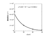
次に、電極構造体11を用いた上述の実施例と同様に、20kVの正極性の直流電圧を針電極12に印加し、平板電極13をアースに接続して、大気圧中で正極性コロナ放電を発生させた。そして、生成されたオキソニウムイオンの個数密度について調べる検証試験を行った。ここでは、電極構造体11から測定位置を離してゆき、所定距離x毎に、電極構造体11で生成されたオキソニウムイオンの個数密度をイオンカウンタ(イオントレーディング社製、商品名イオンカウンタ NKMH-103 (超ワイドレンジ型)で測定した。その結果、図5に示すように結果が得られた。
Next, as in the above-described embodiment using the electrode structure 11, a direct-current voltage of 20 kV positive polarity is applied to the needle electrode 12, the flat plate electrode 13 is connected to ground, and positive polarity corona under atmospheric pressure. A discharge was generated. And the verification test which investigated about the number density of the produced | generated oxonium ion was done. Here, the measurement position is separated from the electrode structure 11, and the number density of oxonium ions generated in the electrode structure 11 is measured at predetermined distances x by an ion counter (product name Ion Counter NKMH-, manufactured by Ion Trading Co., Ltd.). The measurement was made at 103 (super wide range type), and the result was obtained as shown in FIG.
図5中、○はイオンカウンタで測定した測定値を示し、実線は測定値を指数関数でフィッティングしたものである。距離x=0cm近辺では、5000万個/cm3程度以上のオキソニウムイオンが生成されていると考えられる。図5に示すように、オキソニウムイオンの個数密度は、距離xを大きくするに従って次第に低下していった。よって、電極構造体11は、分解処理する有機物に近い位置に設置し、オキソニウムイオンを有機物に直接到達させることが望ましいことが確認できた。
In FIG. 5, ○ indicates the measured value measured by the ion counter, and the solid line indicates the measured value fitted with an exponential function. It is considered that around 50 million ions / cm 3 or more of oxonium ions are generated around the distance x = 0 cm. As shown in FIG. 5, the number density of oxonium ions gradually decreased as the distance x was increased. Therefore, it has been confirmed that it is desirable that the electrode structure 11 be placed at a position close to the organic substance to be decomposed and that the oxonium ion be allowed to directly reach the organic substance.
次に、オキソニウムイオンの乾燥能力を評価する検証試験を行った。ここでは、十分な量の水を吸収させた高分子吸収体(以下、含有高分子吸収体と称する)を100gずつ取り分け、4つの含水高分子吸収体を用意してそれぞれ容器(タッパー)に入れた。そして、電極構造体11を用いた上述の実施例と同様に、20kVの直流電圧を針電極12に印加して正極性コロナ放電を発生させ、生成したオキソニウムイオンを、1つの目の含水高分子吸収体に照射した。
Next, a verification test was conducted to evaluate the drying ability of the oxonium ion. Here, 100 g of a polymer absorbent (hereinafter referred to as a contained polymer absorbent) having absorbed a sufficient amount of water is divided into four, and four water-containing polymer absorbents are prepared and placed in containers (tappers) respectively. The Then, as in the above-described example using the electrode assembly 11, a direct current voltage of 20 kV is applied to the needle electrode 12 to generate positive polarity corona discharge, and the generated oxonium ion is used as the water content of the first eye. The molecular absorber was irradiated.
2つ目の含水高分子吸収体には、比較例1として用意したマイナスイオン・オゾン発生器(村田製作所製マイナスイオン発生器MHM305、及び村田製作所製マイナスイオン/オゾン発生器MHM306)を用い、マイナスイオン及びオゾンを照射した。マイナスイオン及びオゾンを照射する際の設定条件は、同様に、複数本の鉄釘に約48時間、マイナスイオン及びオゾンを照射し続けた。印可電圧は、製品の仕様で2kVである。
For the second water-containing polymer absorbent, using a negative ion / ozone generator prepared as Comparative Example 1 (negative ion generator MHM 305 manufactured by Murata, and negative ion / ozone generator MHM 306 manufactured by Murata), Irradiated with ions and ozone. Similarly, the setting conditions for irradiating the negative ions and ozone continued to irradiate the negative ions and ozone to the plurality of iron nails for about 48 hours. Applied voltage is 2kV according to product specification.
3つ目の含水高分子吸収体には、比較例2として用意したマイナスイオン発生器(村田製作所製マイナスイオン発生器MHM305、及び村田製作所製マイナスイオン/オゾン発生器MHM306)を用い、マイナスイオンのみを照射した。マイナスイオンを照射する際の設定条件は、製品の仕様で印可電圧は2kVとした。
For the third water-containing polymer absorbent, the negative ion generator (Murata negative ion generator MHM305 and Murata negative ion / ozone generator MHM306) prepared as Comparative Example 2 is used, and only the negative ion is used. Irradiated. The setting conditions for the negative ion irradiation were 2 kV for the applied voltage in the product specifications.
4つ目の含水高分子吸収体は、オキソニウムイオンやマイナスイオン、オゾン等を照射せずに自然乾燥させた。
The fourth hydrated polymer absorbent was naturally dried without being irradiated with oxonium ions, negative ions, ozone and the like.
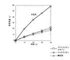
そして、これら4つの含有高分子吸収体について、それぞれ12時間毎に48時間経過時までの蒸発質量と残存質量を測定した。その結果、図6及び図7に示すような結果が得られた。図6及び図7では、実施例の測定結果を「本装置」とし、○で示している。また、比較例1の測定結果は□で示し、比較例2の測定結果は△で示し、無照射時の測定結果は×で示している。
Then, the evaporation mass and the residual mass were measured for each of the four contained polymer absorbents until the lapse of 48 hours every 12 hours. As a result, the results shown in FIGS. 6 and 7 were obtained. In FIG. 6 and FIG. 7, the measurement result of the example is referred to as “this device” and is indicated by ○. Moreover, the measurement result of the comparative example 1 is shown by (square), the measurement result of the comparative example 2 is shown by (triangle | delta), and the measurement result at the time of non-irradiation is shown by x.
ここで、残存質量はタニタのKD-192で測定し、初期質量から残存質量を引くことにより、蒸発質量を求めた。図6及び図7から、マイナスイオン及びオゾンを照射した比較例1や、マイナスイオンのみを照射した比較例2は、蒸発質量及び残存質量が無照射のときとほとんど変わらないことが確認できた。
Here, the remaining mass was measured by KD-192 of Tanita, and the evaporation mass was determined by subtracting the remaining mass from the initial mass. From FIGS. 6 and 7, it was confirmed that Comparative Example 1 in which the negative ions and ozone were irradiated and Comparative Example 2 in which only the negative ions were irradiated were almost the same as in the case of no irradiation.
これに対して、実施例である、オキソニウムイオンを照射した場合は、比較例1や比較例2、無照射のときと比較して、蒸発質量が極めて大きくなり、また残存質量が極めて小さくなることが確認できた。
On the other hand, when the oxonium ion is irradiated, which is an example, the evaporation mass becomes extremely large and the residual mass becomes extremely small as compared with the comparative example 1 and the comparative example 2 and the case of no irradiation. That was confirmed.
次に、上述した検証試験と同じ含水高分子吸収体を用意し、含水高分子吸収体から50cm程離した位置に実施例の電極構造体11を設置した後、含有高分子吸収体に対してオキソニウムイオンを照射した。含有高分子吸収体について、12時間毎に48時間経過時までの蒸発質量と残存質量を測定したところ、図8及び図9に示すような結果が得られた。
Next, the same water-containing polymer absorbent as in the verification test described above is prepared, and the electrode structure 11 of the embodiment is placed at a position about 50 cm away from the water-containing polymer absorbent, Irradiated with oxonium ion. When the evaporation mass and residual mass were measured up to 48 hours every 12 hours for the containing polymer absorbent, the results as shown in FIG. 8 and FIG. 9 were obtained.
図8及び図9では、比較例として無照射のときの測定結果を示している。図8及び図9に示すように、電極構造体11を含水高分子吸収体から50cm程離しても、蒸発質量が極めて大きくなり、また残存質量が極めて小さくなることが確認できた。よって、電極構造体11を含水高分子吸収体から50cm離しても、水の蒸発量を十分に確保できることが確認された。
In FIG. 8 and FIG. 9, the measurement result at the time of no irradiation is shown as a comparative example. As shown in FIGS. 8 and 9, even if the electrode structure 11 is separated from the water-containing polymer absorbent by about 50 cm, it is confirmed that the evaporation mass becomes extremely large and the residual mass becomes extremely small. Therefore, it was confirmed that the amount of evaporation of water can be sufficiently secured even when the electrode structure 11 is separated from the water-containing polymer absorbent by 50 cm.
次に、2つの容器(タッパー)を用意し、各容器内にそれぞれ水を100ccずつ入れた。そして、1つ目の容器には、容器から5cm程離した斜め上位置に、電極構造体11を設置した。次いで、容器内の水に対して、電極構造体11で生成したオキソニウムイオンを照射した。なお、残りの容器の水はそのまま放置した。そして、12時間毎に48時間経過時までの水の蒸発質量と残存質量をそれぞれ測定したところ、図10及び図11に示すような結果が得られた。
Next, two containers (tappers) were prepared, and 100 cc of water was placed in each container. And the electrode structure 11 was installed in the 1st container at the diagonally upward position which spaced apart about 5 cm from the container. Next, the water in the container was irradiated with the oxonium ion generated in the electrode structure 11. The water in the remaining containers was left as it was. Then, when the evaporation mass and the residual mass of water up to the time of 48 hours were measured every 12 hours, the results as shown in FIG. 10 and FIG. 11 were obtained.
実施例として、オキソニウムイオンを照射した場合は、放置したときと比較して(図中、無照射と表記)、蒸発質量が極めて大きくなり、また残存質量が極めて小さくなることが確認できた。
As an example, when the oxonium ion was irradiated, it was confirmed that the evaporation mass becomes extremely large and the residual mass becomes extremely small as compared with the case where it is left (in the figure, described as no irradiation).
以上のように、針電極12及び平板電極13を筒状の電極支持部材14で支持し、かつ20kVという高い直流電圧を針電極12に印加した実施例では、5cmや50cm離れた箇所でも水の蒸発に大きな効果を奏することが確認できた。実施例のような構成とすることで、電極構造体11で生成されたオキソニウムイオンの飛行速度は速くなり、オキソニウムイオンがより遠くまで飛んでいると推定される。
As described above, in the embodiment in which the needle electrode 12 and the flat plate electrode 13 are supported by the cylindrical electrode support member 14 and a high DC voltage of 20 kV is applied to the needle electrode 12, water is obtained even at 5 cm or 50 cm apart It could be confirmed that it had a great effect on evaporation. With the configuration as in the example, the flight speed of the oxonium ion generated by the electrode structure 11 is increased, and it is estimated that the oxonium ion is flying further.
なお、上述した実施形態においては、送風機3から排出された気体を、導入口を介して筐体8内に導入するようにした場合について述べたが、本発明はこれに限らない。例えば、ブロアなどの排気装置機を格納槽2の外部排気口に設け、排気装置機により格納槽2内の気体を外気に排出することで、筐体8内の気体を格納槽2に引き込み、これにより導入口から筐体8内に気体(外気)を導入させるようにしてもよい。この場合であっても、筐体8には、導入口から気体が導入し、排出口から格納槽2内に気体を排出することができる。
In addition, in embodiment mentioned above, although the case where the gas discharged | emitted from the air blower 3 was introduced into the housing | casing 8 via an inlet was described, this invention is not limited to this. For example, an exhaust device such as a blower is provided at the external exhaust port of the storage tank 2 and the gas in the storage tank 2 is exhausted to the outside air by the exhaust device, whereby the gas in the housing 8 is drawn into the storage tank 2 Thereby, gas (outside air) may be introduced into the housing 8 from the introduction port. Even in this case, gas can be introduced into the housing 8 from the introduction port, and the gas can be discharged into the storage tank 2 from the discharge port.